Embed Size (px)
Citation preview

INSTIIUTO NACIONAL UE TECNIGA AERONAUTICS
"ESTEBAN TERRAEAS"
MAERID, SPAIN
O P B I F I R E S
A N D
T R A N S P O R T O P F I R E B R A N D S
P r i n c i p a l I n v e s t i g a t o r
G. Sanchez T a r i f a
Colab o r a t o r a "•
P . Pe rez de l No ta r i o
]?. Garc ia Morono
A. Linan M a r t i n e z
A. B o l l a i n Sanchez
MAY 3 1 , 1962 - MX 3 1 , t9S3

OPEN FIRES AND TRANSPORT OP FIREBRANDS
SIMMARY
a) Open Fires
During the report period the research, work. on. open fires has boon directed, mainly, to the study of firo burning ratoso
A thoorotical nodol of the process of the combustion of a liquid fuel contained in a vessel has boon dovolopcdo This nodol gives stationary as well as transient burning raton of the fuol and tenperaturo distributions within the vessol as a function of the anount of heat received through the fuol svrfs,co„
Dinonsionloss results are shown as well as several nuuorical applications for n-hoptane, iso-octano, benzene, ethyl-alcohol and dioxano o
An oxtense r'~search program is being carried outr in ordor to verify the thoorotical conclusions and in crd^r to obtain basic information on the conbustion process.
The research facilitios are, essentially, the sane ones described in First Annual Report, although they h°vo boon inprofed and several radiometers have boon installed*
3ovoral experimental results are shown as wc.1.1 a: a comparison between theoretical am"' experimental results-
Some Interesting conclusions are obtained on t>io Open Fires program which are included at tho end of the Roporto
^) Transport of Firobrands
Theoretical and experimental studies on the problem of transport of firebrands have shown that an excel' 'rnt approximation of the process is obtained by assuming that the iirebrands fly at their terminal or final velocity of fall.
By means of numerical integrations of tho differential equations of the process and by means of analytical calculations it is shown that in a natter of seconds the firebrands roach values of their velocities very close to tho terminal velocity of fall.
Therefore, flight paths are calculated, undor such assumption, and the experimental tests in the wind tunnel are carried out at wind speeds oqual to tho firobrand terminal velocity of fall.

This is achieved "by reducing continuously tho wind spood in the tunnol during the tost, in order to keop equal the valuos of tho aorndynanic drag and the weight of tho particle. This is controlled by tho position of tho wire holding tho firebrand or else by tho recorded curves of such weight and drug*
An cxtonse rosoarch progran is also being carried out,with firebrands of several kind of woods (pinus pinaster, pice;*", oxcolsa, quercus sossiliflora, populus trenuloidos and ochrona lagopus) with spherical and cylindrical shapes and for difforent noisturo contents.
Tho snail wind tunnel described in First Annual Report is being used, A largo wind tunnel has boon deaignod an-! constructed and it will be soon utilizcdo
Several results arc- shown and discussed, including flight paths of the firebrands for several wind conditions»
Sono important conclusions arc obtained on the Transport of Firebrands progran which are included n'~< tho ond of tho Report*

- t -
I, - . OPM FIRES
t-i Introduction
The rosoarch work, on Open JFiros has been especially
dedicated to tho theoretical and experimental studios on turning
rates.
A theoretical model of tho process of the combustion of
a liquid fuel contained in a cylindrical vessel has "boon develop
ed, which gives tho "burning rates and temperature profiles within
the fuel as functions of tho amount of heat rocoivod by tho fuel
from the flame* Transient conditions have also been considered
in order to evaluate tho time nooded to p,ttain quasi-estationary
combustion conditions, which in certain cases may bo oxtromoly
long*
The research facilities utilized havo been, basically, the
same ones described in the First Annual Report. An improved
systom for measuring the fuel flow has been placed. A ring with
four radiomotors has been fitted around and over the fire, as
well as a moving systom of probos for measuring flamos temperatures
and convection speeds. Hocording thermocouples have also boon
installed.
An oxporimontal research program is being conductod using
several types of fuels in order to verify the theoretical results
and in order to obtain moro information on tho combustion procosa.

- 2 -
BURNING RATES. = = = = = = 3 3
THEORETICAL STUDIES
1-2 Combustion Process in a Vossol
The combustion process of a fuel in a constant-lovol vossol
can "be divided into the following periods:
a) Heating and ignition
The fuel is hoated from an external source (a flamo) until
its surface roaches the flash point temperaturo, and than, combus
tion begins.
3s) Combustion and surfaco heating
When combustion starts the fuel surfaco temperaturo
incroasos very rapidly until it roaches the boiling temperature.
c) Transient combustion at constant fuel surfaco temperature
Combustion proceeds at constant fuel surfaco tomporaturo.
Temperature within the fuel incroasos and tho burning rate also
incroasos both tending towards stationary values*
Tho time required for periods a) and b) is very short as
compared with tho timo of period c). However, thoso periods can
not be disregarded because they fix tho initial tomporaturo
conditions for tho transient combustion. Eor simplicity, periods
a) and b) will bo joined in only one period, which will bo called
heating and ignition, in which the fuel is heated until. it3
surface reaches the boiling temperature. Burning rat© (fuoi
consumption) will bo disregarded throughout this process*

- 3 -
d) Stationary combustion
After a certain time combustion roaches, practically,
stationary conditions, which can be directly calculated.
1-5 General assumptions
The physical model of tho transient or stationary combus
tion process will be based upon tho following assumptions:
a) Tho fuol enters the vossel through its bottom at ambient tem
perature T0 * This temperature is kept uniform and constant
throughout tho bottom by moans of water cooling at T « The fuel
moves upwards till it roaches tho surfaco whore it is evaporatod
and burned. This fuol surface is kept at a constant lovol (fig.l).
In other models it will bo assumod that part of tho fuol is
removed from the fuel surfaco without burning by moans <->•<: overflow
tubos.
b) One-dimensional conditions within tho vessel will bo considered
by assuming that vessol diameter is largo as compared to vossol
dopth and by assuming that conditions at the fuol surface aro uniform.
c) Yiscosity and gravitational forces aro not considorod* Density,
thormal conductivity and specific heat of tho fuol aro taken as
constant regardless of fuol temperatureo
d) It will bo assumed that a certain amount of hoat Q per unit s
surface and per unit time is transferred from the flame to the fuel
through either conduction, radiation or convection. It will be
assumed that Q is absorbod at tho fuel surfaco, disregarding tho
dopth of the fuol required to absorb tho hoat transferred through.

- 4 -
radiation* The values of Q will bo experimentally obtained.
e) Tomporature at the fuel surface will be taken equal to the boil
ing temperature at ambient pressure,
f) Par the case of the ignition period the general assumptions will
be the samo, except that combustion will be substituted by a heating
process in which the fuel will bo at rest.
1-4 General Equations
Under the aforementioned assumptions the equations of (40
conservation of mass and energy within the fuel are as follows:
a) Continuity:
p V = ms = constant (1)
in which p is the fuel density9 V the upwards velocity of the
fuel and m s is the burning rate or mass of fuel burnt per unit
time and per unit area.
b) Energy:
Neglecting the kinetic energy of the fuel, the equation of
energy expresses the transport balance of heat and internal energy.
2_ nlL\ - p Y AislL = P JLISL (2) or else:
Jx * "ST pc" "3x2" VJ;
c) Motion:
Neglecting the transfer of momentum within the fluid, tho
See Appendix for Notation.

- 5 -
equation of motion -vanishes, roducing to :
P = constant (4)
throughout tho fluid.
1-5 Boundary Conditions
a) Combustion
At the fuel surface wo have tho following boundary condi
tions:
X = Xs ; I = Ts C5)
v' s
in which ejn is tho latont heat of evaporation* This equation
expresses the heat balance at the fuel surface.
At the fuel bottom, vie have:
X = 0 ; I = I (7)
b) Ignition
During ignition, condition C5) doos not exist and oquation
(6) is*
s
At tho initial time (t =o) , wo also havo:
t = o T (X) = I = constant (9)
For T = T , the resulting toiaporaturc distribution I (X) will
be the initial condition for studying transient combustion.

- 6 -
1-6 Solution of tho Equations
Introducing the dimonsionloss variables and paramotors:
(to)
111)
9
I
z
2 a
X s
* i
\?
%
* e
=
=
=
=s
=
r=
=
£ =
T
a
X
t
£.2. A
%*s
AT s
* s c
a 2 X V a
a
T s ""5j
s
Ct2)
C13)
(14)
(15)
(16)
(17)
(18)
equation (3) and boundary condi t ions ( 7 ) , (5) t (9)» (6). and (.8) aro
cxproaaod, r e s p e c t i v e l y , as fol lows:
- 7 -
0 = © ; or : © (0 X) = &ft C20) 0=0 ° ° .
0J_1 = ©s » t ; or : © (t,T) * t (.21)
&C=o * Go ; o r : 9 $> 0 ) = 9 o <-22)
(x) = (U-\ a V = o U^^=i
C24)
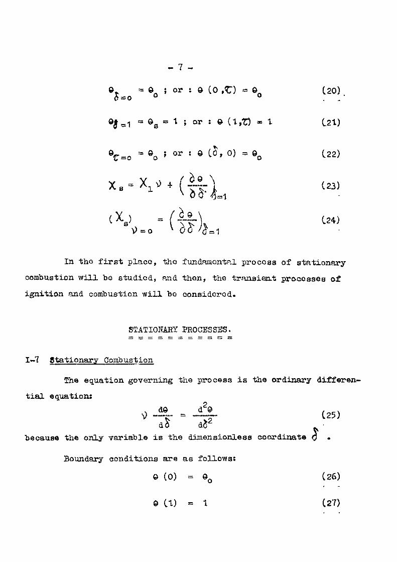
In the first place, the fundamental process of stationary
combustion will bo studied, and then, the transient processes of
ignition and combustion will bo considered.
STATIONARY PROCESSES.
1-7 Stationary Combustion
The equation governing the process is the ordinary differen
tial equation:
9 = _ (25)
dd d^
because the only variable is the dimensionless coordinate J . Boundary conditions are as follows:
0 (0) = 9Q (26)
© CD = 1 (27)

- 8 -
*.-x** (Irk, in which 9 , JL and /C are constant and their values are given.
Parameter \jl , which gives the fuel velocity Y and burning rate
ms =s o V , is constant, hut its value has to be determined.
Equation (25) is inmediately integrated, resulting:
0 = -i- J C1 4- exp [v)( $ -C2)] I (29)
Boundary conditions (26) and (27), give:
Q . _ ...—.••—.,.»-, ,1 • in n ..J,., ( 3 0 )
1 - e •
(3t)
Resulting: * e* - e*d
© = 1 - (1 - © Q) _ _ (32) e - 1 • -
The value of fundamental parameter \) is obtained from
boundary condition (28) and from:
^ £) S ij = 1 ov - t
Substituting this value into (28), it results:
1 /.. . o 1 - *,
X X, V s o* - 1 /
from which the valuo of \} can be obtained.
~ 9 -
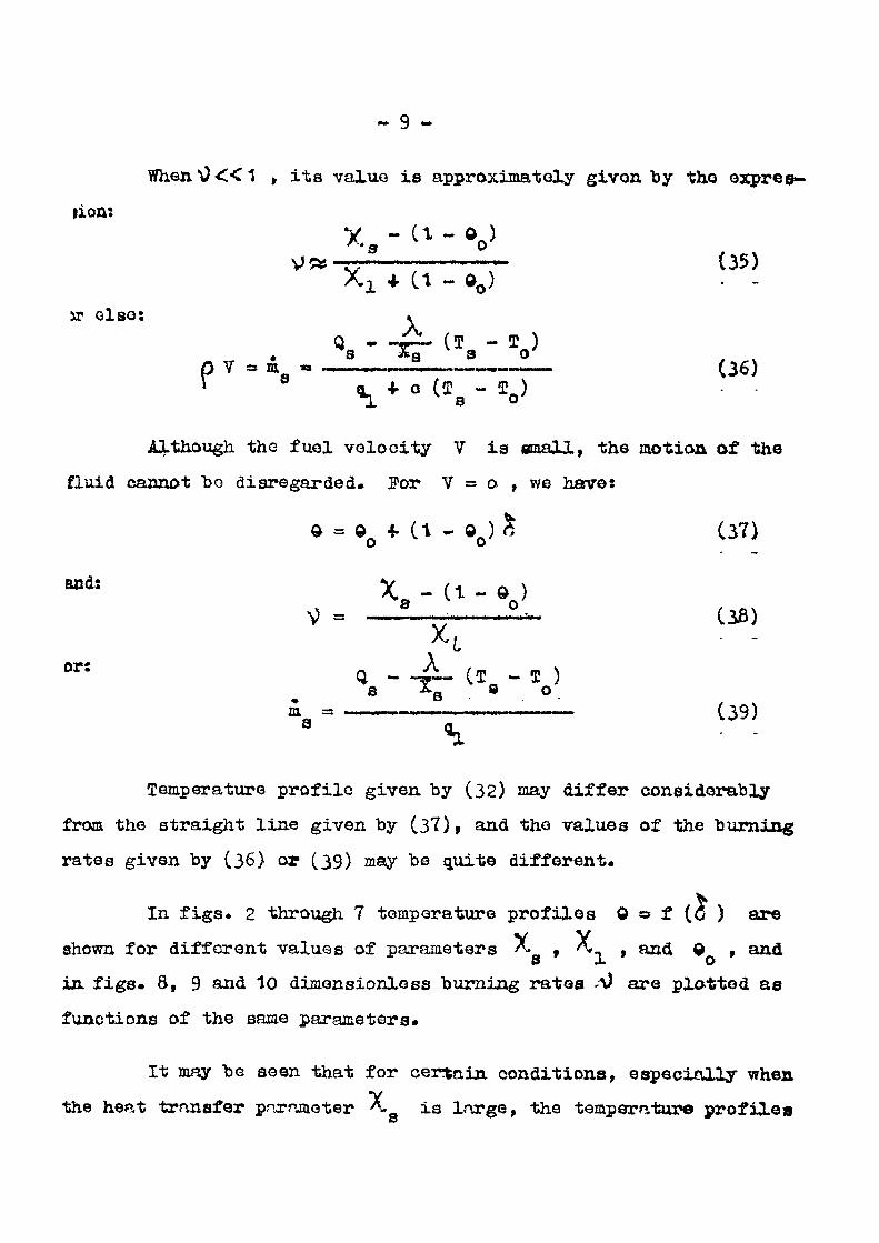
When*0«1 , its value is approximately givon by the expres-
ji on:
y&~~ (35) * 1 + Ct - ©0)
jr else: * Q _ «« (J - I )
. S Jtg 3 0 P V = a » «.<'i. — . — • — . . . . . . - . . . — . . > . • .... (3^) 1 8 ^ + o ( S B - S„)
Although the fuel velocity V is small, the motion of the
fluid cannot bo disregarded. For V = o , we have:
© = ©Q 4. (t - 00) & (37)
and: *8 -( t - V
V = _ i - i- (36) A» j • -
Q - J L CI - I ) a « i (39)
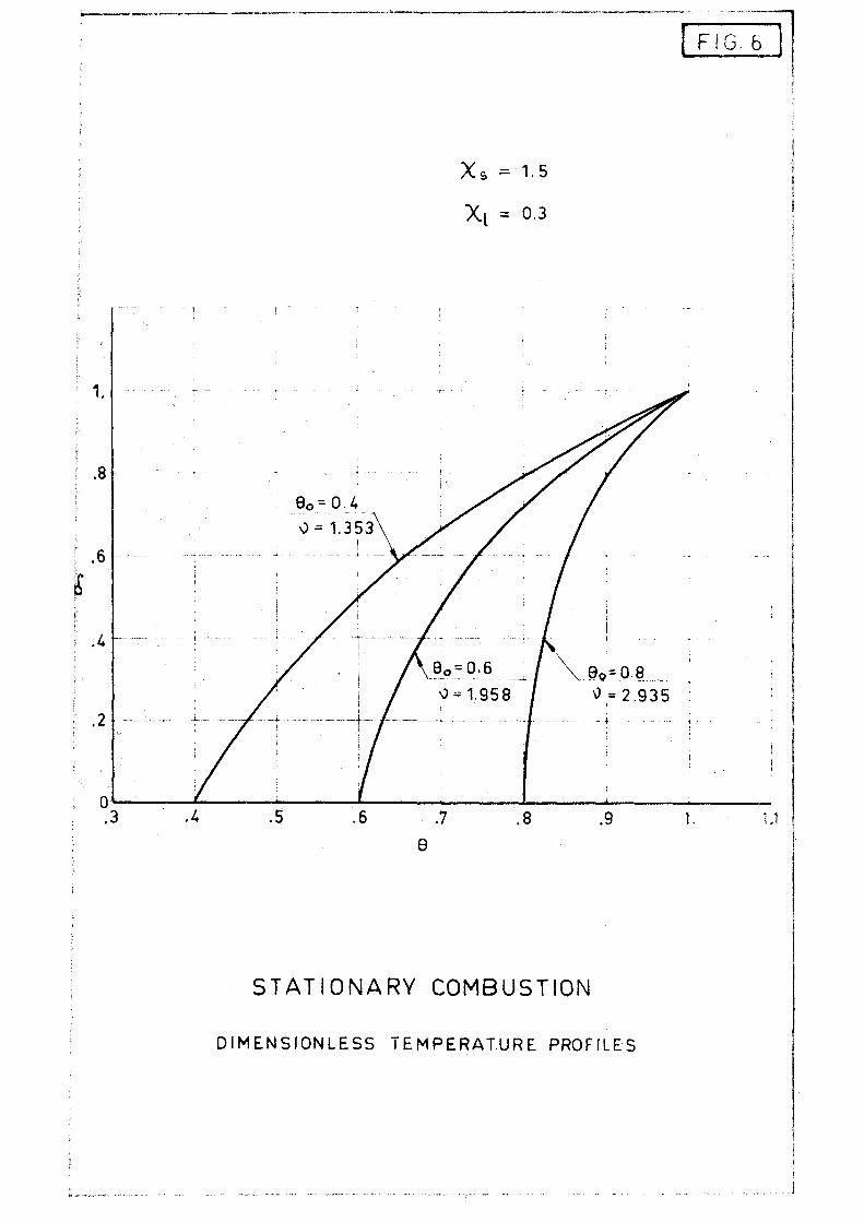
Temperature profile given by (32) may differ considerably
from the straight line given by (37), and the values of the burning
rates given by (36) or (39) may be quite different*
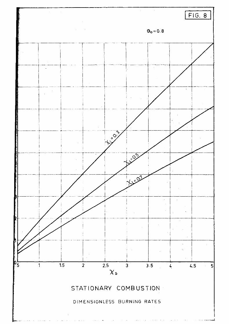
In figs. 2 through 7 temperature profiles Q » f (o ) are
shown for different values of parameters A» , A* , and 9 , and
in figs. 8, 9 and 10 dimensionless burning rates sd are plotted as
functions of the same parameters.
It may be seen that for certain conditions, especially when
s the heat transfer parameter A. is large, the temperature profilea
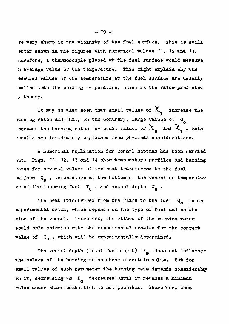
- t o
re very sharp in the vicinity of the fuel surface. This is still
etter shown in the figures with numerical values 11, t2 and 13,
herefore, a thermocouple placed at the fuel surface would measure
n average value of the temperature. This might explain why the
easured values of the temperature at the fuel surface are usually
mailer than the boiling temperature, which is the value predicted
y theory.
It may be also seen that small values of X increase the
turning rates and that, on the contrary, large values of Q
.ncrease the burning rates for equal values of X and A. . Both
•esults are inmediately explained from physical considerations.
A numerical application for normal heptane has been carried
mt. Figs. 11, 12, 13 and 14 show temperature profiles and burning
rates for several values of the heat transferred to the fuel
surface Q , temperature at the bottom of the vessel or temperatu-s
re of the incoming fuel TQ , and vessel depth X .
The heat transferred from the flame to the fuel Q_ is an
experimental datum, which depends on the type of fuel and on the
siae of the vessel. Therefore, the values of the burning rates
would only coincide with the experimental results for the correct
value of Q3 , which will be experimentally determined.
The vessel depth (total fuel depth) Z_ does not influence
the values of the burning rates above a certain value. But for
small values of such parameter the burning rate depends considerably
on it, decreasing as X decreases until it reaches a minimum s
value under which combustion is not possible. Therefore, when

- T1 -
using vessels for studying open liquid fires, depths larger than
those minimum values should be used.
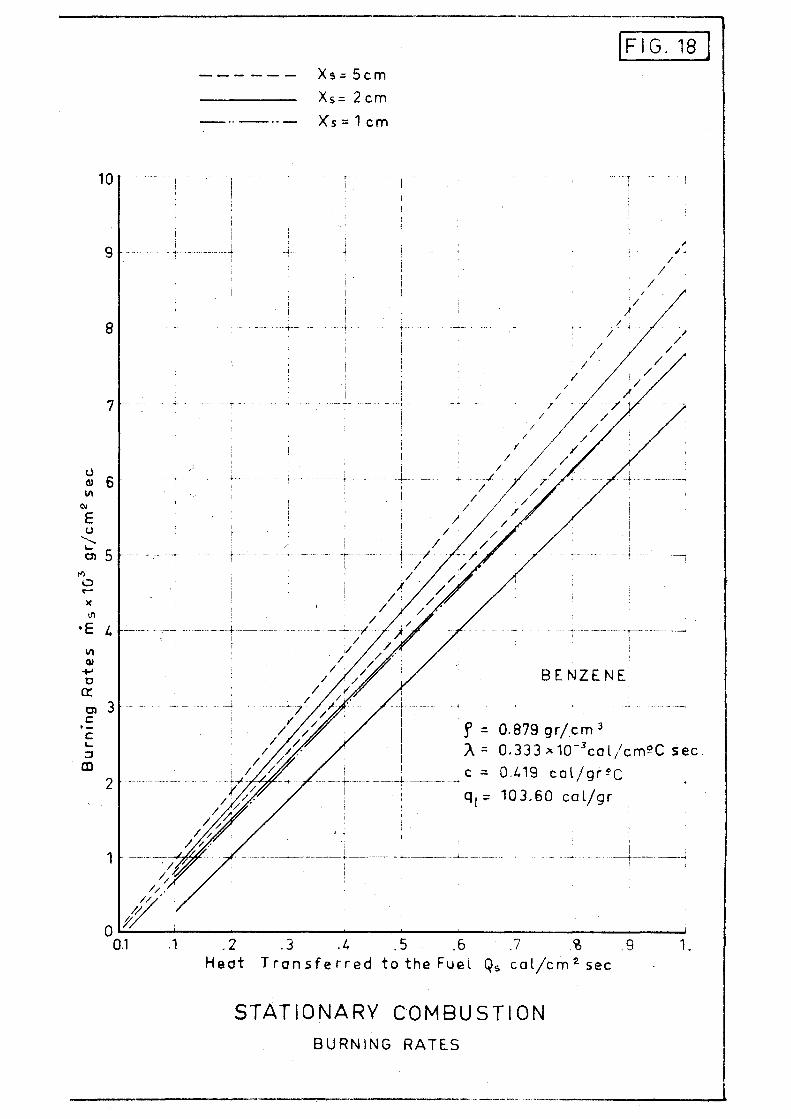
In figs. 15 through 18 similar results are shown for
benzene, from which the same conclusions could be derived.
Finally, figs. 19 and 20 show comparative results of tem
perature profiles and burning rates for normal-heptane, benzene,
iso—octane and ethyl-alcohol.
1-8 Stationary Combustion with Overflow
When using constant level cylindrical vessels for studying
open fires, in order to keep the fuel at a constant level one or
several overflow tubes are used. The overflow tubes can be placed
outside the vessel, as shown in fig.4 of First Annual Report, but
quite often, the overflow tubes are placed within the vessel. In
this case it is necessary to introduce some modifications into the
general equations of the process, since not all fuel which iB
heated up to the boiling temperature is evaporated and burned, but
a certain percentage of it is returned down through the overflow
tube. We will see that this return flow influences considerably
the values of the burning rates.
The equation of energy:
a* . a , a2* P7 — B-.Tr =A~ai~ Uo)
is the same (25) than in the previous case. But in this case
ig - p V is the flow of fuel introduced into the vessel but it is
not the amount of fuel which is evaporated and burned.
- T2 -
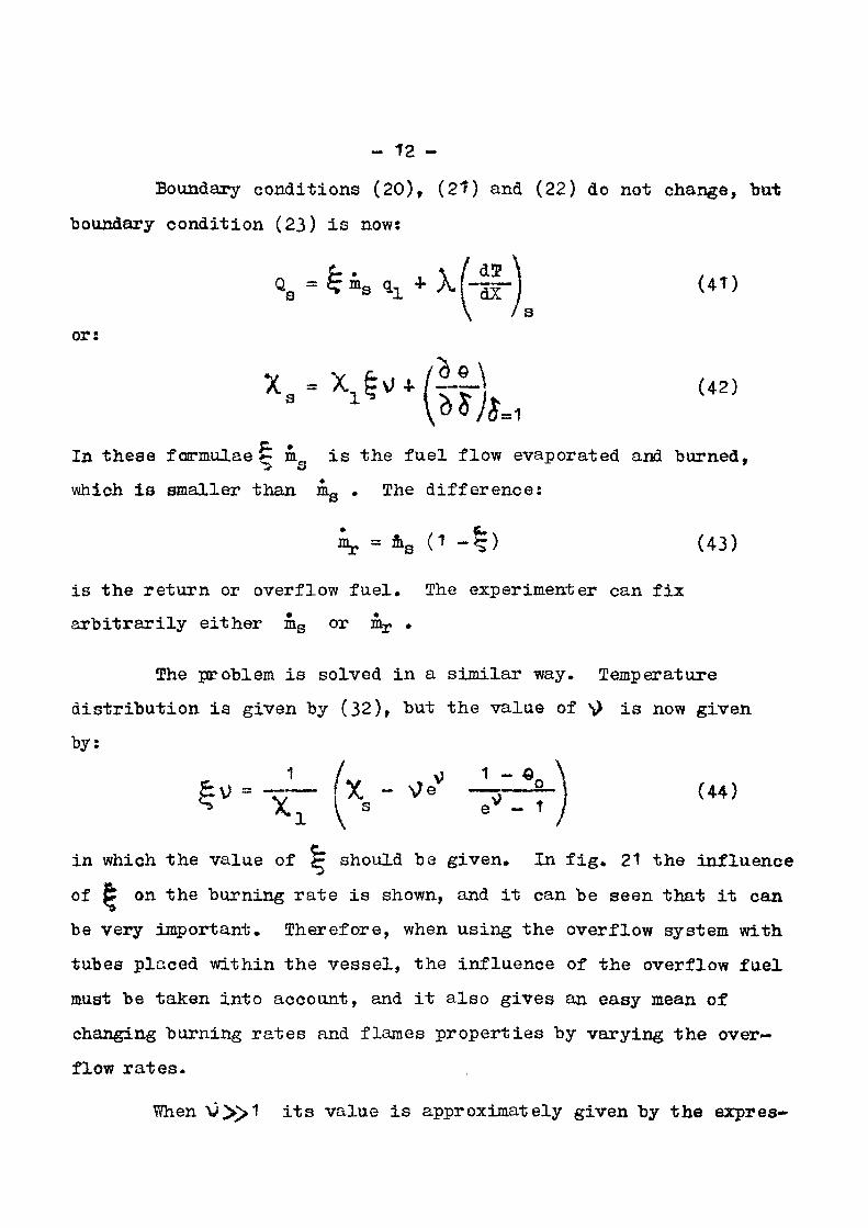
Boundary conditions (20), (2?) and (22) do not change, but
boundary condition (23) is now:
S^ £ *s ax + M 4 r j (41)
or:
"••^"(fik & •
In these formulae e m„ i s the fuel flow evaporated and burned, :> s *
which is smaller than ms . The difference:
^ = ms (1 - | ) (43)
is the re turn or overflow fuel . The experimenter can fix
a rb i t ra r i ly either ms or mr •
The problem i s solved in a similar way. Temperature
dis t r ibut ion i s given by (32), but the value of ^ i s now given
by:
&m ~xT (x*" "'* " ^ ) U4)
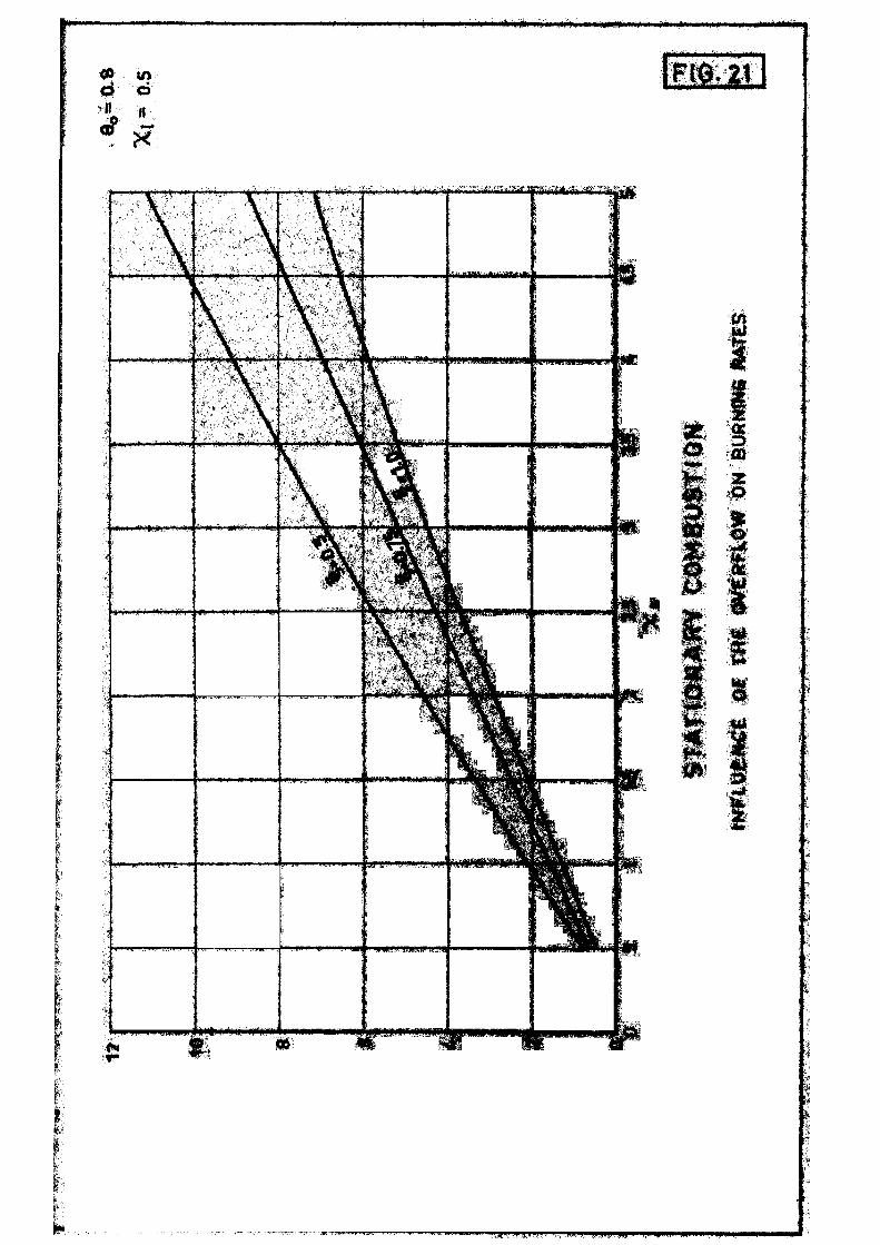
in which the value of F should be given. In fig. 21 the influence
of & on the burning rate is shown, and it can be seen that it can
be very important. Therefore, when using the overflow system with
tubes placed within the vessel, the influence of the overflow fuel
must be taken into account, and it also gives an easy mean of
changing burning rates and flames properties by varying the over
flow rates.
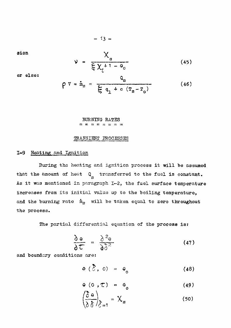
When V>>1 its value is approximately given by the expres-
axon
or else:
- T3 -
X V? = 1 (45)
£ y i t - e n
Qs V = ms = ~ - (46)
g q + c (T S -T Q )
BURNING RATES
TRANSIENT PROCESSES
1-9 Heat ing and I g n i t i o n
Dur ing t h e h e a t i n g and i g n i t i o n p r o c e s s i t w i l l be assumed
t h a t t h e amount of hea t Q t r a n s f e r r e d t o t h e f u e l i s c o n s t a n t . s
As it was mentioned in paragraph 1-2, the fuel surface temperature
increases from its initial value up to the boiling temperature,
and the burning rate ms will be taken equal to zero throughout
the process.
The partial differential equation of the process is:
and boundary conditions are:
*?. <47>
« (5\ o) = eQ (48)
(49)
(50)

- H -
The general so lu t i on of the parabol ic p a r t i a l d i f f e r e n t i a l
equation (47) i s :
© - C1 * C 2 5 4. X An e n s i n (Oi^f 4 - f n ) ( 5 t )
Oondition (50) g ives :
. ^ 2 n - 1 __ . . ^ n + Tn = 5 * ( 5 2 )
or:
C2 = X s (53)
Condition (49) g ives :
? a « 0 (54)
or
C1 - « 0 (55)
Prom (54) and (52) : (2 n - 1) jr.
u>n a _ (56)
r e s u l t i n g :
(2 n - ? )* .$ s i n r (57) 0 * 0 0 4 - X 0 5 * X An exp - ( 2 n - t ) V r / 4
Finally,, condi t ion (48) g ives :
Z An s i n (2 n - 1 ) | £ « - Xg $ (58)
Prom which, by mul t ip ly ing by s i n ] ( 2 m - 1 ) ^ 0 / 2 j do and
in t eg ra t i ng from 0 = 0 up t o 0 = 1 , i t i s obtained:
8X n A = - 2 2 _ . (-1) (59)
n 11 ( 2 n - 1)2

- ?5
Resulting, f ina l ly , for the dimensionless temperature:
8 X S rri (-1) n
s J l 1 ( 2 n - 1 ) 2 exp (2n-1)Vrn
— sin (2n-t)7l
(60)
£
The ignition period ends when © =
time T* is given by the expression:
0 • The corresponding s
exp 1 (2 n-t);
2 2 ( 2 1 1 - 1 ) *
^s 71 8X s
(t - o **s;
(6T)
For this value of c the distribution of temperatures is given
by (60) for Z = Z .
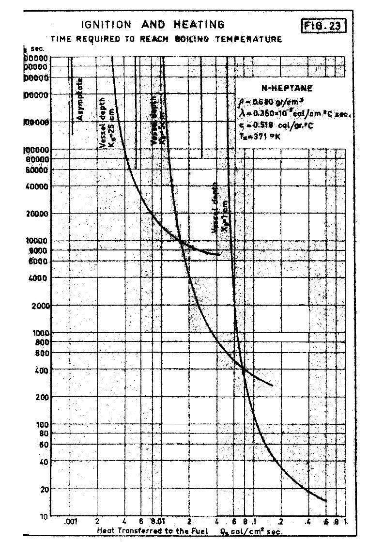
In fig.22 the dimensionless time % required to reach s
the*boiling temperature is represented as a function of heat
parameter X. for several values of Q , and in fig. 23 a numeri-
cal application, for normal—heptane is included.
In all practical cases, the actual time t is very small,
but if Q_ is small, especially for large values of the vessel
depth, such time may be very long and it could not even be possible
to reach the boiling temperature, for very small values of the heat
transferred % •
I-fO Transient Combustion
In order to study the transient combustion process the
complete equation (3) should be used. However, the analytical
integration of this complete equation does not appear as feasi-

- 16 -
U e W
The problem can be solved by means of numerical integrat ion
of the equation. However, an approximated analyt ical solution can
be obtained by disregarding the influence of term Y0T/OX on
the d i f ferent ia l equation (3)> and obtaining the value of velocity
V or burning r a t e mg through boundary condition (6) .
Term Y© S/OX i s usually small as compared with terms
OT/Ot and A/ J> 2T/C X2 , because the flow velocity Y i s very
small. By comparing terms v b T / d X and A/ <) T/CX2 for the
stationary case and from resu l t s obtained through numerical
integration of the complete equation in a representat ive case, i t
has been estimated that the error introduced in the value of the
burning r a t e by disregarding such term i s , usually, of the order
of 20-40$, although in certain cases i t may be l a rge r . However,
t h i s approximation presents the inconvenience that i t does not
f u l f i l l boundary conditions for t = co , for which the solution of
the problem should tend towards the stat ionary solution of equation
(3) .
Through the change of var iable:
dY ay
equation (3) is transformed into the equation:
0t c ^ V 2
which could be integrated, but boundary conditions (5) and (7)
cannot be introduced into the general solution of this equation.
- V -
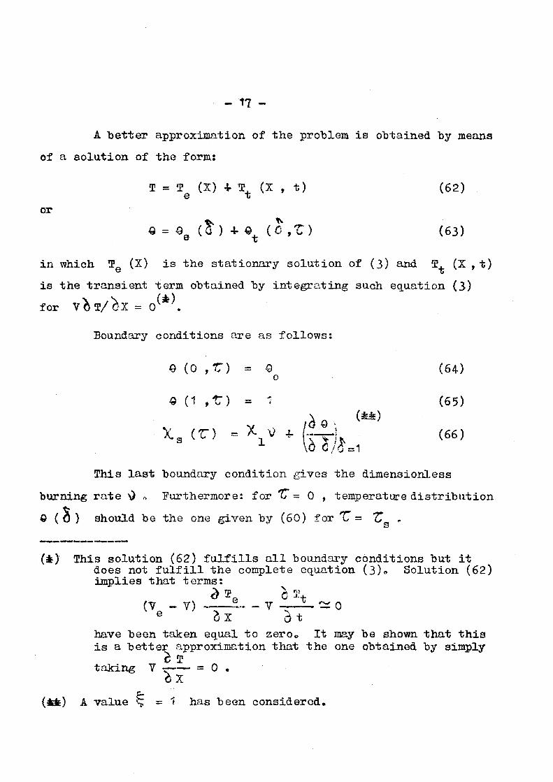
A b e t t e r approximation of t h e problem i s obtained by means
of a so lu t ion of the form:
0? = T (X) + S. (X , t ) (62) e t
or Q = Q& (I) ArQ^ (0 ,Z) (63)
i n which T0 (X) i s the s t a t i ona ry so lu t ion of (3) and 3?, (X , t )
i s the t r a n s i e n t term obtained by i n t e g r a t i n g such equation (3)
for v i l / ^ X = 0 .
Boundary condi t ions are as fo l lows:
0 (0 ,V) = Q (64) o
« (1 ,*) = ' (65)
Xa CC) -r- X„V 4- (-—-!, (66) 3 ' " ' x ' " \blll This l a s t boundary condi t ion gives the dimensionless
burning r a t e \) a Furthermore: for 'V - 0 , temperature d i s t r i b u t i o n
) should be the one given by (60) for u = T, „
(*) This so lu t ion (62) f u l f i l l s a l l boundary condi t ions but i t does not f u l f i l l t he complete equation (3)° Solut ion (62) implies t h a t t e rms:
(7 _ Y) ~ - V -—i- ~ 0 e £x St
have been taken equal to zeroc It may be shown that this is a better approximation that the one obtained by simply
taking Y = 0 . h
(*!E) A value <£ = f has been considered.

- 18 -
The stationary term QQ (0 ) is given by (32). Therefore,
the problem consists in the attainment of transient term Q (6,T)» t
This term i s given by the t r a n s i e n t term of the so lu t ion
of equat ion:
l-h • Kr w with boundary condi t ions (64-) and (65)» This term i s :
G+ ( 0 , T ) = X K e s i n nTld (68) t 1 n
Therefore, so lu t ion (63) i s :
e - e m 2 2 - . v « = 1 - (1 - a ) 4- T AM e~n * ^ s i n n * 0 (69)
ev - 1 1
Coefficients A are determined by equalizing the expres
sions of Q given by (60) and (69) for % = *C and XI- 0 , and s
then , by mul t ip ly ing by s i n m 7T.0 and by i n t e g r a t i n g from
$ = 0 t o 6 = It results:
n * ° ^ - 1 j n K e"* -1 3|T5 [ 71 .
2 2 i f - ^ 1 - 1 64 " n_ $£. { (2m-1) 71 . X. ( -1) n L. e*P
Jt3 S ^=1 "'-l L i ) 2 f ( - - 2 •-2' (2m-1) ' (2m-1) - + X
(70)
Dimensionless burning r a t e i s obtained from boundary
condition (66) and from t h e value of (OQ/QO)^ obtained from 0=1

- 19 -
(69)» I t r e su l t s : oo 2 P
Y - X A nJt(-1)n e_n n. r ^ . _ ( 7 1 )
in which A i s given by (70).
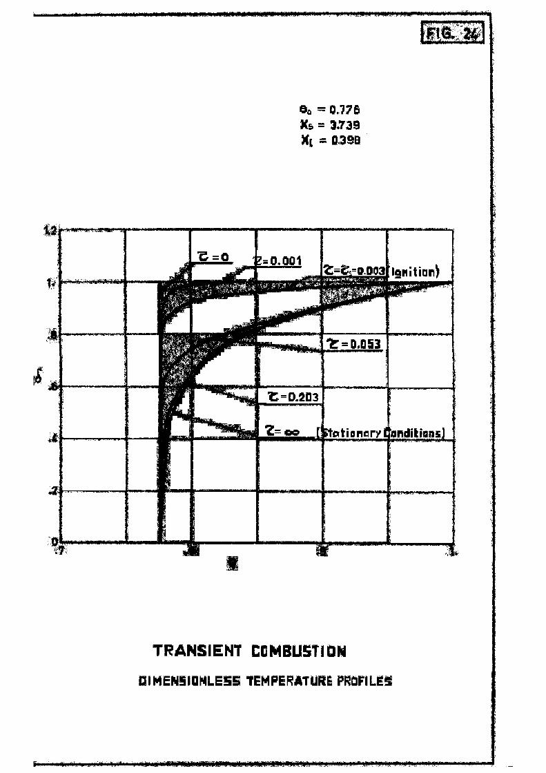
In figure 24 dimensionless temperature prof i les Q = f (0)
are shown as a function of dimensionless time u . The i n i t i a l
heating and igni t ion period, from % - 0 to T = *C i s also
included. I t may be seen that such time T7 i s very small. I t s
is also interesting to point out that temperature profiles are
especially sharp during transient conditions.
Pig.25 shows dimensionless burning rates ^ as a function
of time. In this case the starting of combustion ("tf = 0) has
been taken as the initial time (TT= 0).
Pigs. 26 and 27 show similar results of normal-heptane,
for an assumed value of Q equal to 0,1 cal/cm^. For this value s
of Q the time required to reach conditions close to the asymp-
totic stationary values is of the order of 30 minutes.
Results obtained by disregarding the motion of the fluid
V -y- ' = Oj have been a3so included, showing that the
approximation utilized is considerably better.
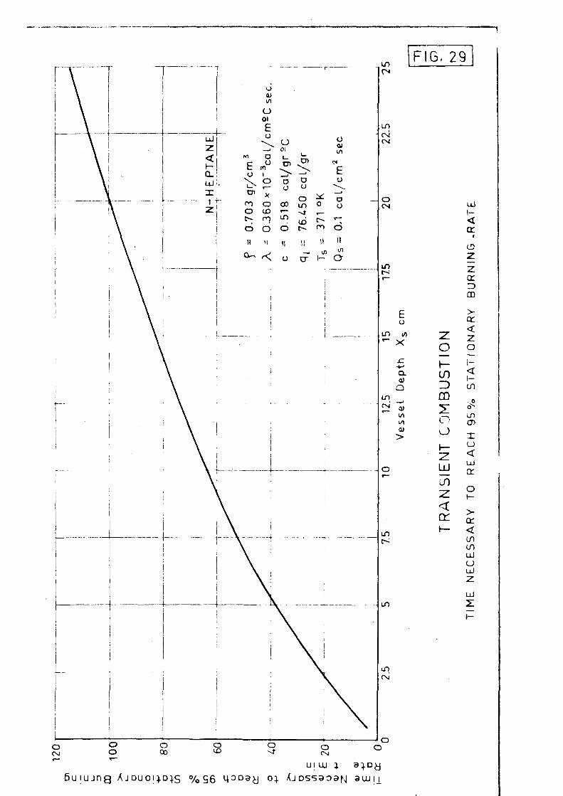
Finally, figs. 28 and 29 show the overh^Hmingly importance
of vessel (fuel) depth X on the time needed to reach conditions s
close to the stationary asymptotic values. In fig. 28 curves

- 20 -
a = f (t) are shown for several values of X • It may he seen 3 S
that the stationary value of the "burning rate depend little on X
above X = 5 cm, and the time needed to reach a value of nig
equal to 95$ of the stationary value changes froin 40 minutes to t20.
This might explain why some experimenters could not reach
stationary conditions when studying liquid fires using deep ves-(*)
sels , and it also shows that vessel depth has to be selected
carefully according to its size and to the type of fuel which is
going to be studied.
BURNING RATES
_EXPmiMM!TAL_ J5TUDIgS_
1-11 Research F a c i l i t i e s
The research f a c i l i t i e s which a re being used t o study open
l iqu id f i r e s a r e , b a s i c a l l y , the same ones as descr ibedin F i r s t
Annual Report, al though they have been considerably improved. A
general sketch of them i s shown i n f i g . 30.
A new cons tan t -pressure volumetric system for measuring
the fuel consumption has been cons t ruc ted . I t gives more accura te
readings and more f l e x i b i l i t y for measuring l a rge or small fuel
consumptions.
The overflow tube has been placed i n the center of the
(*) Ref. 1 of F i r s t Annual Report .

- 21 -
vessel. We have seen that the overflow rate influences considerably
the process. By setting different overflow rates, the burning rate,
the heat emitted by radiation and several other variables can be
continuously modified, which may give very important informations
on several aspects of the problem.
A grid with different siaed holes has been placed at the
bottom of the vessel, in order to have a more uniform distribution
of the incoming fuel*
A ring with four Eipp and Zonen Radiometers has been placed
over the fire, and their signals are registered in a recording
Hartman and Braun instrumentP
A moving system of probes has been placed. Several pres
sure and temperature probes have been attached to a moving
carriage,which can be displaced by remote control along horizontal
and vertical axiSo "his system permits measurements of flame
temperatures and velocities at continuously variable location
during the experiments.
Finally, an optical pyrometer has been acquired and the
reflectivity of an aluminum mirror in the wavelength region of the
red light has been measured at the Optical laboratory of the INTA,
in order to measure flames temperatures by optical means.
1-12 Research Program
An extense experimental program is presently being conduct
ed, comprising the following measurements:

- 22 -
VO Burning rates and temperature profiles within the fuel.
20) Radiant heat emitted by the flame
3fi) Flame sia* and flame lateral surface (from, movie piotures)
4*0 Flame temperatures at several locations.
From these measurements information is being obtained on
the following subjects:
a) Values of the heat transferred from the flame to the fuel
as well as its laws of variation with several parameters, such as
fuel properties, vossol size, flamo tomporaturo, etc. (This heat
transferred will also br- directly measured by placing a small
radiometer at the end of a tubo inso -tod in the vossol.)
b) With tho values of the heat transferred to the fuel,
burning rates and tomporaturo profil" s will be aaiculatod following
tho theoretical model already described* Those r-suits will bo
compared with those directly measured.
c) Scaling laws. She influence of vessoi siae,vessel depth
and flame size on th~ problem- will bo studiod» For a givon vessel
and for the same fuol, flame size can bo varied considorab3y by
changing the overflow rato.
Puro ch'iaical species are mainly being used as fuels,
especially normal-heptane, benaeno, octane and ethyl-alcohol.
Ethylono-dioxido (dioxano) is also being usod, mixed with viator
in several proportions.
Information on soveral problems of liouid fuoX-£uw) is being
studied, especially in connection with radiation properties and

- 23 -
|cat balances of flames.
This experimental program and the comparison of thcorotioal
tnd experimental results is in full progression now, and it will
Constitute one of the main subjects on open fires for tho next
annual period* Some preliminary results will bo given in tho presont
Report*
Pigs. 31? 32 and 33 show threo examples of tho type of
(measurements which arc being carried out.
Pigs. 34 and 35 show the values of (X, , Qp/ Af an<*
Q^/qms D Av as function of time. Q is the total heat emitted
by radiation, through tho upper hemisphere calculated from data of
figs.31 and 32« QR/A^. is the average value of the radiant heat
chitted per unit area of tho flame, and Qj>/|* a O^ A is tho
ratio of such radiant h-at to the heat released by combustion,
(a, = heat of r<action).
Finally, assuming that all heat received by tho fuel is
transferred through radiation,and talcing as the value of such ra~
uiant heat the average value of Qn/A^ , tho valuo of Qs may bo
stimated. Prom the value of Q , and with the values of the ovcr* s
low coefficient |~ of figures 31 and 32, the values of the burning
•"atos for n-heptanc may b. calculated by applying the theoretical
model already described. In this way, curves of fig. 36 havo
been calculated and the calculated values of (F m arc comparod
with tho values directly measured with the volumetric motor.
There is a fair agreement botwoon tho calculated and

- 24 -
the measured values, although, as it could bo oxpectod, tho
calculated values are somewhat smaller. Vossol diameter is 25 cm,
mid for this size souo appreciable amount of hoat should bo
transferred through conduction. Thorcforo, the estimated value
of Q is probably snallor than its actual valuo, which might, s
explain the slight discrepancy between calculated and measured
values of the burning rates*
II. TRANSPORT OF FIREBRANDS
II~t INTRODUCTION
During the report period the following work has boon
perforaod on tho firebrand program:
a) Continuation cf the theoretical work on flight paths.
b) Modifications of the research facilities and constructions
of new ones.
c) Continuation of the experimental work on lifetimes,weight
and aerodynamic drag histories and flight paths of burning
particles of wood.
Tho theoretical research has "been appliod to the study of
actual flight paths, by moans of numerical integration of tho
differential equations of tho process. From those studies a
simplified model of flight paths has been derived, which gives an
excellent approximation of tho process. This model assuaos that
tho firebrand always flies at its toruinal velocity of fall.

- 25 -
The experimental results mentioned in paragraph c) were at
first dotoruinod by burning wood particles in a small wind tunnel
at constant wind spoods.
According to tho aforementioned conclusion that tho
firobrandsfly at thoir torainal volocity of fall, the experimental
work is presently being carried out at variable wind spoed. By
changing progressively tho throttling of tho tunnel the wind spood
is kept continuously equal to tho terminal volocity of fall of tho
burning particle, which docroasos throughout tho combustion procoss
tending towards &cro.
A remote control of tho wind spoed of tho tunnol has boon
fittod, and a larger wind tunnel has boon dogsignod and constructed,
which will be soon utilized.
THEORETICAL STUDIES
II-2 Plight Paths
The two-dimensional equations which control tho motion of
a burning particle under stationary wind conditions arc as follows:
Z~ 4- - X ~ £ _ w w = 0 (72) dt 2 m x
dwv OC-n A JL. 4- - i ~ £ — w wv - g = 0 (73)
dt 2 m *
(*)
{Chose equations were derived in first Annual Roport.
(*) Soo Notation in Appendix

- 26 -
Parameter:
* * - - ~ (74) 2 m
is a function of t ime as well as of t h e r e l a t i v e wind ve loc i t y w.
The experimental par t of t he r e sea rch program c o n s i s t s i n
the determinat ion of function ©t = f (w , t ) for severa l i n i t i a l
sizes and shapes of the f i r ebrand , kind of woods and moisture
contents . At the same time l i f e t i m e s or burn-out time of the
f irebrands t . = f (w, t ) a re determined.
From the experimental values of c*. , and under given wind
conditions u ( x , y ) , from equations (72) and (73) t he f l i g h t
paths a r e determined:
,tb (76) Y = / (uy ~ V dt
/o
The burn-out t ime t^ can be longer or shor t e r t h a t t h e
time requi red for a f i rebrand to reach the ground ("ty-o)• In "the
f i r s t case the f i rebrand reaches t h e ground s t i l l burning and i n
the second case t he f i rebrand burns out i n the a i r . When t , = t _ b y=o
a maximum horizontal range is reached.
lt-3 germinal Telocity of Fall (Final Velocity)
In First Annual Report flight paths were obtained by taking
an average value of parameter ©c . For Cd constant an analytical

- 27 -
solution of system (72), (73) was obtained, and one of tho principal
conclusions was that tho burning particles roaoh vory rapidly
their final velocity or terminal veloaity of falX, oharaotoriaod
by conditions*
w x « 0 (77)
Wy « Wf a A L J L *78*
Several num. rical integrations of systom (72) (73) havo boon
performed for different representative casos, by taking tho
experimental values of pa-araotor Ct (w, t) • Adam1 s method has
beon utili&od, by using expression:
2
dwx
dt /n
At (79)
and a s imi la r expression for wy •
In f igs* 37 and 38 two repr^sentat iy /3 casos aro shown fo r
"pinus p inas to r " spheres with i n i t i a l diamotera of 17 ma and
25 mm. jtn i n i t i a l valuo of •«_,. _ = 20 m/soQ has boon taken and
for tho v e r t i c a l component two casos have bGon considered:
w,, rt = 20 m/soo and w = 0 • Tho f i r s t would aorrospond to y,o <- / y ? 0
tho initial flight of a firebrand takon upwards by tho convection
column produood by the firo<> Tho second caso would correspond to
a firebrand leaving the convection column at a certain height boing thrown into a horizontal wind at a z.oro vertical oomponont
of its velocity.
Tho experimental valuos of tho terminal velocities of fall
aro also shown in tho figures. It may bo soon that in all casos

- 28 -
in a matter of seconds both components of the velocity w and
w tend very rapidly towards aero and towards wf respect ively.
In fig.39 the time needed for the pa r t i c l e s to reach a
value very close to i t s asymptotic value (wx = o w = w^) i s
compared with the burn-out time, and i t may be seen tha t i t i s
extremely small. Therefore, i t i s jus t i f ied to assume that the
firebrand i s always flying at i t s terminal velocity of f a l l for
the calculation of f l ight paths . However, since some cases may
exist for which such approximation could not be admissible} in the
following paragraphs two expressions are derived which give a
maximum value of the error introduced by the aforementioned
assumption.
II-4 Maximum Errors in the Flight Paths
The errors introduced into the horizontal and ve r t i ca l
distances reached by a firebrand owing to the introduction of the
assumption that the firebrands always fly at wx = o and w~ =wf ,
may be expressed by the expressions:
?t "x d t
£ _ - . -
ft j „ at
<80)
c
"x** -
r%2
wx dt
j (wf - wy ) dt
r 2 U y C t g - t ^ - / wy
d±
»* *f
to
j ( w f - V d t
M»»II—* • ! • • • •
* y ( * 2 - * l )
( 8 t )

- 29 -
In these expressions t. is the final time, equal to t 0 or
to t-jj (to the one which is the longest) and tp - t is the time
during which the firebrand is climbing (t^ = 0 , w = u. »Wy>w^)
or falling (t2 = tf , w y > 0 = 0 , wf > w y ) .
Expressions will be derived giving the maximum or limiting
values for £ and £ v . •X y
According to equation (72), the derivative dwx/dt and
the relative velocity w are always of opposite sign. Considering -X.
that parameter <X i nc reases as t ime progresses and t h a t i n t h e
normal case the i n i t i a l r e l a t i v e ve loc i t y wx 0 i s p o s i t i v e , we have
d wx dt ^ «*o w w x > °^owx (82>
in which <* i s t he i n i t i a l value of parameter ex . I n t e g r a t i n g , o
i t r e s u l t s :
w ^ ^ o , Q ) ( 8 }
1 4-<* w t 7
o x,o
which i s introduced i n to (80) , g ives :
log (1 +c* w t ) log (1 +<* I L t ) £ « 2-^ i£_;L- = ^ £JZ_L. (64)
because normally wx 0 = u . .
It may be easily verified that in all cases of practical
(*) In First Annual Report velocities wx and wy were defined "as relative velocities of the wind with respect to the firebrand". This definition was adopted in order to havo positive numerical values of such velocities.

- 30 -
interest is <* u . t^^>0 and, therefore, £* *s very small.
For the cases of figs. 37 and 38 <* u t_ is larger than 125 and O J» X
£ x is small than a 4$.
For very small values of tf or for a very low velocity
of the wind £ may have large values, but both cases are of no
practical interest because the distances reached by the firebrands
would be very small.
Parameter di is inversely proportional to a linear
dimension of the burning particle, and the final time, taking
equal to the burnt-out time (for maximum fire range), is roughly
proportional to a linear dimension of the particle* Therefore,
the maximum error given by (84) does not depend on the size of the
particle.
Similarly, for the vertical component w and considering
the case of a free fall (t1 - tQ , t2 = tf , w Q = 0 , wf> w ) ,
we have:
£_ = g - 1L 2 + wv2 w r ^ g -£tf0 vtv
2 (85) ~^— - * - j «x -• -fr- "y & -o "y
from which it is obtained by integration;
W y < ^ 7 e^(t-to) _ 1 • «*,° 7 x ^ 7 7 7 (86)
whera: 4 / Y = y « g (87)
"f,o - Y^7 J-=(« f) (88) 0 t = t 0

- 31 -
t is the time at which the particle starts falling, and OC and o o
f,o are the corresponding values of coefficient oi and terminal
velocity wf •
In formula (86) it may be verified that in a few seoonds
w_ changes from zero to a value very close to w« • x f»o
Since w^ 5* wy and wf -£ w„ , formula (81) gives:
/ f,o - V dt
(89)
and taking (88) into (89), it results:
1 4* e 2t(tf-t0)
£y * uy ( t f - t 0 ) ]«*»» ( t * - v -**><>[Y 1OS
- (tf - *0) f (90)
It may be easily verified that if tf - tQ or u are not too
small, £ is very small and tends towards zero when tf — tQ
tends towards infinity.
EXPERIMENT! RESULTS .
II-5 Research Facilities
All experimental data have been obtained in the small wind
tunnel described in First Annual Report. A remote control of the

- 32 -
throttlo andaby-pass intake havo boon fitted in ordor to carry
out tho tosts at variable wind spcod.
Another wind tunnel has boon designed and constructed,
siuilar tn tho snail wind tunnol, but considerably largor
(fig. 40)• This wind tunnel uses an axial 6 HP blowor and a
fixed exhaust and wind spcod control systen, but two calibratod
intake nozzles can be adjusted, one of 52 en in dianotor and
o-thor of 32 en.
Wind speeds up to 40 n/soc can bo roachod in tho tunnol
and pieces of wood up to to en in length or diauetor can bo
tested.
The nozzles aro calibratod jot onginos intakes. Wind
velocity is dotcrninod by measuring thj static prossuro at four
points locatod around the poriphcry of the test section, wind
speed is controlled by ncans of a throttle andaby-pass intake
The firobrand is sc^ported by ncans of a thin stool wiro.
Tho woight and aorodynanic drag arc noasurcd by noans of a two-
conpononts strain-gauges balance or olso, tho particle is
allowed to hang freely fra.i tho wire, till it roachos a 45*
angle fron the vortical position, when tho woight and tho aero-
dynauic forces arc in oquilibriun.
A four channels recording oquipnont has boon rocontly
acquired, for registering the strain-gaugos signals as wolX as
tho pressure signal fron an electric nicronanonotor which will
bo acquired.

- 33 -
II-6 Research Program,
The theoretical treatment of the problem of transport
of firebrands is well established. Also, a quite satisfactory
experimental technique has been determined and the research
facilities arc almost finished.
An extense experimental research program is now being
carried out, and it will constitute the bulk of the work on the
firebrand problem for the next reporting period.
The comparison, analysis and scaling laws of results will
bo made when all experimental data arc available. Therefore in
the present Report only some typical results will be advancod.
Transport of firebrands of pine wood ("pinus pinaster"),
spruce ("pice^ cxcelsa"), poplar ("populus troEiuloidos") > oak.
("quoreus scssiliflora") and balsa wood ("ochroma lag-opus")
are or will be studied with moisture contents of 2> and 25c/».
At present definite geometrical initial shapes havo been
soloctod: spheres, cyxmders and platos. Li tor on,natural shapes
will also be studied.
Until now, most of the experimental work has boon
realised with shporionl firebrands of pinus pinaster wood .-Some
rosalts have also boon obtained with spruco and poplar firebrands
and somo data with cylindrical initial shapes are also available.
All results hav^ been obtained m the email wind tunnel.
(*) It has not boon possible to obtain "quorqus rubra" wood.

- 34 -
The experimental technique has been as follows:
The wood particles are suspended by a thin steel wire at
the test section. The particle is ignited with the flame of a
butane torch, keeping the flame on the particle during a time
which is determined by the condition that the burn-out time of the
firebrand has a maximum value compatible with complete combustion.
At first, some experiments were carried out by burning
wood particles at constant wind speed. Afterwards, once it was
established that the firebrands fly at their terminal velocity of
fall along practically the whole flight paths, the experiments
were made by varying the tunnel wind speed keeping its value equal
throughout the test to the decreasing terminal velocity of fall of
the burning particle. Until now, such condition has be ca controlled
by the position of the wire, which is mantained at a 452 angle
throughout the test*
In the large wind tunnel when using the Micrograph
recorder, such condition of equal values of both velocities will
be established by the recorded curves of weight and aerodynamic
drag of the firebrand. Both values will be kept equal throughout
the test by reducing continuously the tunnel wind speed.
At present, the wind velocity has to be read very
frequently by an experimenter during the test. A direct reading
non-recording micromanometer is being used. It is intended tp use
an electric micromanometer, and its signal will be recorded on the
Micrograph.

- 35 -
Figs. 4»1 and 42 show typical results obtained with pinus
spheres. Wood is not an houogonous substanco, and when burning
spheres of equal initial siztf a severe scattering of results ia
unavoidable. Therefore, average VRIUQS for oach initial diameter
have to bo taken as shown in such figures.
In Pigs. 43, 44 and 45 average values of tho terminal
velocity of fall or final velocity w~ as function of tino aro
shown for different si&od sphoros of pino, spruce and poplar woods.
In tho last part of tho combustion process of the
firebrand, the particle very frocucntly breaks. Therefore, tho
last part of the curves is not woll dotorriined. However, this has
little influenco on the over-all conbustion process.
Pig.46 shows sinilar results obtained with cylindrical
firebrands. The cylindors arc hold in a transverse position
regarding to the wind spood becauso in a froo flight this position (*)
would bo approximately taken by tho firebrand
iron tho results shown in figs. 41 through 46 the flight
paths of the firobrands are calculated with formulae (75) and
(76) once tho wind conditions are established.
In Research Progress Report No. 3 sone exanplos of flight
paths were shown.
Pigs. 47 and 48 show tho flight paths for spherical and
[*) In a froo fall a particlo balancos around tho position of maximum stability, which is tho position of maximum aerodynamic drag.

- 36 -
ylindrical firebrands under a wind nodol which assunos a vortical
lonvection column and a horizontal wind.
The firebrands are assuned to be taken upwards by tho
sonvoctive wind and in sone point of the convection column they
ire thrown away and picked up by tho horizontal wind.
It nay be scon that there exists a critical height KL for
irtiich tho firebrand reaches a naxinun distance on the ground still
jurning. This naxinun distance is the "naxinun range X- n of
fire spread.
If the firebrands leave tho convection colunn at heights
lower than Yn they reach the ground still burning but at
distances snallor than X . On tho other hand, if the particles
leave tho convection colunn at heights higher than Y^ they
burn out in the air before reaching the ground-
Finally, figs. 49 and 50 show flight paths for spheres
and cylinders for a wind nodol in which tho convection colunn is
assunod to be inclined and with a given width. Bosults are
qualitatively sinilar to those already discussed.
A conparison and discussion of rosults for several shapos,
types of wood, noisturo contents, wind Eiodols, etc. will bo loft
for the next Report, whon all the oxporinontal data already
progrannod will bo available.
- 37 -
PRINCIPAL CONCLUSIONS
The principal conclusions includod in the present Report
iro as follows:
a) OPEN FIRES
\) Burning rates and temperature profiles are theoretically
obtained as functions of the brat r ceivod by the fuol pox*
unit time
2) </hon it is assumed that such h -at is transferred exclusively
through radiation, a fair approximation of the process is
obtained, for normal-hoptanc fuol and for vessels larger than
25 cm in diameter.
3) Vessel or total fuol dopth influences considerably the process
when it is smaller than a certain minimum value.
4) Liquid dopth influences considerably the time required to
achieve quasi-stationary conditions, and that time may bo
oxtromcly long.
5) Prom 3 and 4 it follows that vessol dopth has to be choson
between certain limits* These limits depend considerably on
the heat Q received by the fuel, that is to say, on tho s
characteristics and siz o of tho flame, and therefore, on the
type of fuel.
6) Temperature profiles arc very sharp in the vicinity of tho
fuol surface. Therefore, a thermocouple placed at tho fuol
surface would measure an avcrago value of the temperature,

- 38 -
somewhat smaller than its superficial value, which should be very
close to the "boiling temperature at ambient pressure.
Temperature profiles are especially sharp for transient combustion.
The amount of overflow fuel taken from the vessel influences consi
derably the combustion process. The overflow rate may bo used as
an additional variable of the process. Large overflow ratos
roduco both the burning rate and the flame size, and convorsily*
TRANSPORT OF FIRKBRANS3
The firebrands reach in a few seconds velocities very close to
their terminal velocity of fall characterized by conditions
w^ = 0 and w = wf »
Only when the burn-out time t~ is very small or the wind speed
very low condition 1) might not hold, but those cases are of no
practical interest.
There exists a critical height Y^ at which if the firebrand
leaves the convection column it roaches a maximum horizontal
distance X still burning.
X is the maximum range from the flame front for which fire
sproad may bo produced by firebrands of given initial size and
for given wind conditions.
In the worst conditions X_ may roach values of the or dor of
several kilometers, even for small firebrands and for moderate
wind conditions-
Madrid, June 1963

- 39 -
A P P E N D I X
NOTATION..
Parameter defined by (13)
Oroas section area of a firebrand
Coefficient
Flame aroa
Fuel surface aroa
Specific hoat of the fuol
Constant
Constant
Brag coefficient
Vossol diamotor. Also, firebrand diamotor
Gravitational constant
Mags of a firebrand (also a number)
Overflow or return flow of fuel
Fuel flow within the vessol
Number
Pressure
Radiant-heat omitted by the flame per unit tim©, through tho upper hemisphere
Heat recoivod by the fuel per unit aroa and per unit timo
Latent heat of evaporation
Heat of tho reaction of combustion
(Time
Burn-out timo
Time a t which a f i robrand roaches tho ground
Final t ime, equal to t. or ^Vc3Q
-. 40 ~
Wind speed
Velocity of the fuol or absolute volocity of a firebrand
Rolativo velocity of the wind with rospoct to a firebrand
Pinal or terminal volocity of fall
Horizontal coordinate for firebrand notion. Also, coordinate for fuel notion within a vessel
Maxinum range reached by a firebrand
Vessel (fuel) depth
Vortical coordinate for firebrand notion
Critical height reached by a firebrand for naxinuu range
Parameter defined by (74)
Dinonsionloss coordinate defined by (It)
Error
Dinonsionloss temperature defined by (10)
Dinonsionloss heat transferred to the fuel surface defined by (14)
Dinonsionloss heat of evaporation defined by (15)
Thermal conductivity of tho fuol
Dinonsionloss burning rato defined by (16)
Fuel or air density
Dinonsionloss tine defined by (12)
Coefficients
Function
o
e
s t
Subscripts „
Indicates initial values Indicates stationary conditions Indicates at the fuel surface Indicator transient conditions Indicate X and Y axis directions.

C ) G . 1
SCHEMATIC MODEL FOR THE COMBUSTION OF THE FUEL WITHOUT OVERFLOW TUBES
• t
Fuel Surfac« t f
Burning cat© rfu
Heat f lux Qc
I "V * »• X » X S ;X»T 5
•dfiM|*«iiM9M«to%iqmM^
T^X|s Const
t V t
£» <4iwiw«iH*HI»«»«q^^ '»i}liii<i ii l i , " ' ' " * " " * * * - * * u i»jniiifiijwi'lin ipiMi
Fuil Bottom XV0;T*TA

Xs=5.0
.FIG. 2
- *
8o=0.4 >
^=3 805' / ^
i r
/ i
j - t
y ' * > « ^
/ 0-4529
I
J 1
i
i •
X
/ ^ *•
/ x
1 \
i
|
^ _ * —
*
• ^
= 0 8 -5.549
i
i
i — i
i
j
|
.8 .9 1.
STATIONARY COMBUSTION
DIMENSIONLESS TEMPERATURE PROFILES

FIG. 3
1.5
0 7
e
STATIONARY COMBUSTION
DIMENSIONLESS TEMPERATURE PROFILES
s

F i - j L
X, = 0.7
e
STATIONARY COMBUSTION
OIMENSIONLESS TEMPERATURE PROFILES
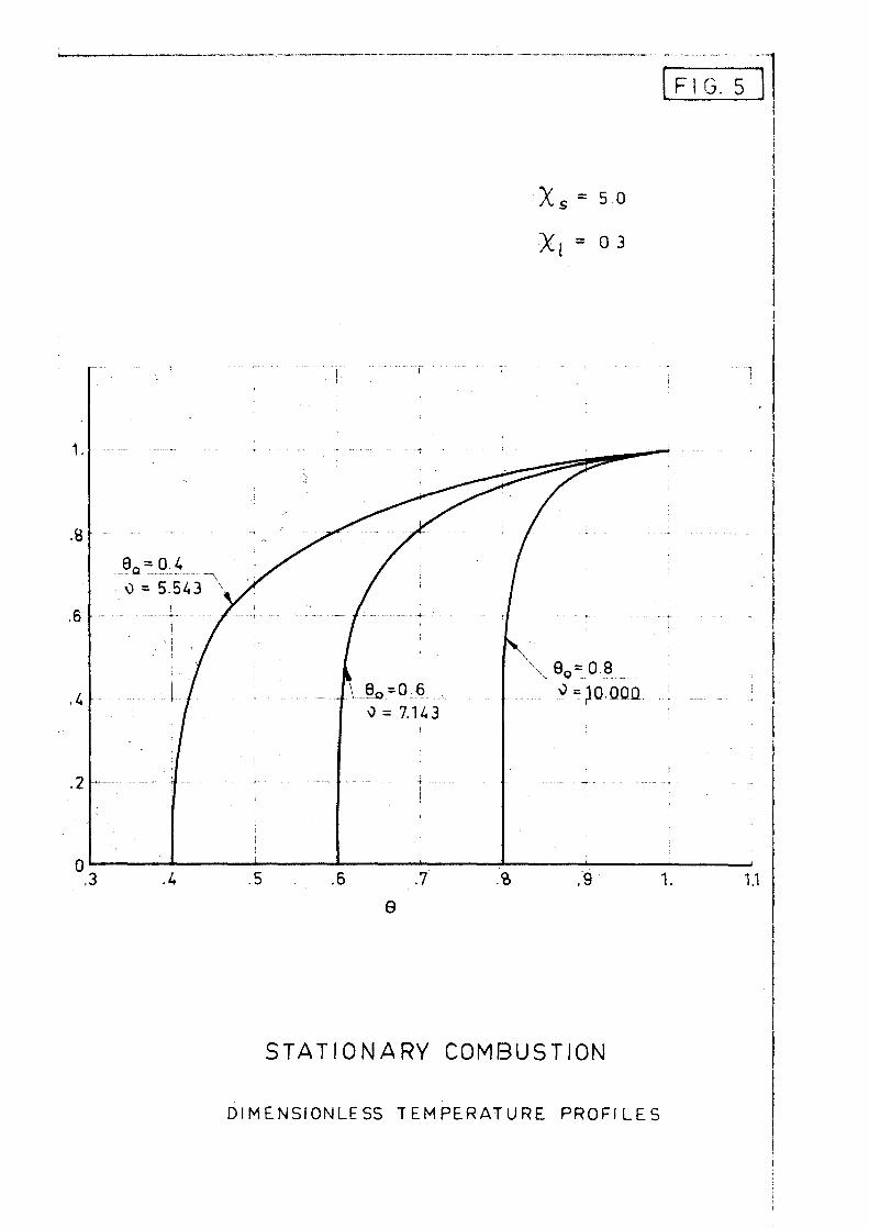
FIG. 5
X s = 5 0
Xi = 03
STATIONARY COMBUSTION
DIMENSIONLESS TEMPERATURE PROFILES
E G. 6
1.5
0.3
,6
.k
.Bo=_P;__4 0 - 1.353
9ftf_Q-8 ^=2 .935
.3
e 1.
STATIONARY COMBUSTION
LI
DIMENSIONLESS TEMPERATURE PROFILES

1.
.8
.6
0 .3
Xs = 0.5
XpO.3
" i . ' ; i | ' | i ' • i
FIG. 7
i "• " " i
iA-Q£Q2
9Q = 0 - 8
^=0.729;
e
STATIONARY COMBUSTION
DIMENSIONLESS TEMPERATURE PROFILES
1.1
r - • " • ~ — — — — — — — — •
I FIG. 8
9 o =0.8
STATIONARY COMBUSTION
DiMENSIONLESS BURNING RATES
_ i

O » o
CD
FIG. 9.
ID
in
in oo
2 : 0
1— CO 3 m
u^
<
CO 2
co
o ^ o
CM
LO
o I — <
- in
LD ro
m
en
o
UJ
5:
f jU—

o I) o
CD
FIG. 10
I D
in
i n 00
CO
ir> tvi
CN
o I— I/) 3 m ?• o (J
> •
< Z o — h-<
en UJ i -<
CD *L
Z
3 CD
to in UJ
z o en z UJ
LO
(/)
U>
r

* 0
00 u"> fN
X 0
CO 00 CM
x: 0
on
rn
FIG. 11
o o <n m
a rn
o
o o n
o
R
:*: o
l_ •D
*-> D
(b a. E &
» — •
i
10 Z> CD
o a > rr < «d o i— < i— in
UJ
<
a. LU X i
2
UJ _ j
u. o a: 0_
UJ
1 -
<r a: in a.
UJ i—

FIG. 12
a 0)
o o
0 o 0
l! vi) o
or -
Oo oo oo tn oo --i-( \ CM n II I!
0 II
E o
in CM
it
X
\
^ . . .
o
oo
o CM
o m
o o
o o> (N
o 00 CN
0
t -
(U l _
r i + J
l _
a. E <u
(—
O
m > o ( )
> en < 7" O
h-< \— CO
U j
z < t—
a. UJ
1
2
CO
UJ _ J
u. O (X. a_ UJ (Y 3 I—
< rr UJ Q_
X UJ
CM O UD CM
wo x
00
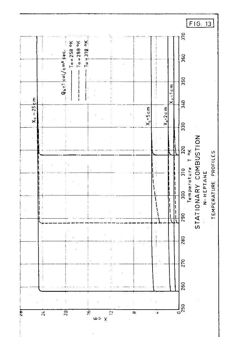
FIG. 13
!
i i
i
r
i 1 i
| j i 1 i
1
i
i
F u
LT5 CM
II
u> X
1 I
|
| I lp
i
| j i !
! t —
i
S.
| 1
!
\ 1
t 1 t i
!
L_
| — 4 - •
1 !
1 1
1 1
— 1 1
t
• • - 1 -
1
> - 1
* : * : O 0
. oo 00
o m oo a» C M C M
-iA_ it II »
Nc o o o
^ — J
o o
11! ifl
ey i
| 1 1 1 1 I i
I
'
i
_ . — r
;
j r_
j
* O !
ooi
<*> if! Oj
•-!
1 1 : | : : i
1 •
!
i
_ _
i
i •.
! \
- —i
i
i i
!
i
1
1
i
. , 1
\
— :
i
•
!
'•'
— t - -
— - r - ~ -
1
E o
i n ii in
X
:..
1
1
1
! ! 1
:
j i i •
*
i
e 1 o i < * * 1 II 1 1/1
X i
^
U 11
V \ \ \ \
- j — J
- 4 i
E o
*— •j)
X
1
v.
—
1 1 1 1 1 .V
1
i I ._
A.
_.
o c-m
o u?
o in
o n
o
o CM v
o
CO
GO o « 51 co a *—' -_
-H O ^ D <
<J» > * Q_
0 Q. a: u £ E < x
*V Z ± O CD CM
O 00 CM
<
CO
ui
o oc a.
UJ
cc
ID
<
cr a. T uJ
CM O CM
(X> CM
wo x 00
CM
O CO CM
o in CM

FIG. 14
f = 0.680 g r / c m 3
A = 0 . 3 6 0 x 1 0 " 3 c a l / c m 2 C sec.
c =0.518 cal /gr<?C
q = 76.450 c a l / g r
.01 .2 .3 M .5 .6 .7 .8
Heat T rans fe r red to the Fuel Qs c a l / c m 2 se"c.
STATIONARY COMBUSTION
N - H E P T A N E
BURNING RATES

£ u
in
X
E u
in X
ujn X
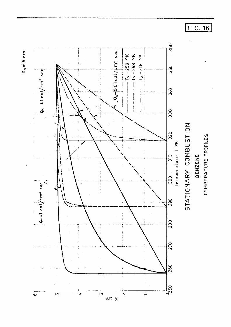
FIG. 16
E u
to II 1/1
o CM C>
O
CO
o o CO
o >-
0> l_
4-> D
4; Q.
e 1—
— y— CO 3 CD T o C)
> Q: <
o
OJ 2 ui N
uJ m
U) uJ —j u. O rr a. uJ tr =>
<[ a: UJ
n
uJ
CO
wo x

G. 17
E o
.A
X
o
o ID en
o
en
O
m
o oo (Nl
o (SI
o CM
o If)
O
o
o n
o o
o CD (N
0
H-
CU i_
-t-« O
a a. e 01
U) Z> CD
o o >
rr <
o
<
CO
UJ 2 uJ M Z uJ CD
C/1 ul _ j
LT O cc Q_
uJ
3
< a: UJ Q_
Z
wo x
Xs= 5cm
Xs= 2 cm
X~s = 1 cm
FIG. 18
0.1 .1 .2 .3 .4 .5 .6 .7 .% .9 Hea t T r a n s f e r r e d t o the Fuel Qs c a l / c m 2 s e c
STATIONARY COMBUSTION BURNING RATES

u
o ot E o
—' 01
iro Ln CD D c-. o-r- ro in b o d H II II
UJ
z < i -o o o tn
o
E o
* o o O 00 00 r _
CN O
11 '1
l - Or
O O
O * o o 00 00 JO CD 00 ^
II II XT *~
E u
II
X
i 1
o A 00 \
CO II
0 ; t — '
m ! II :
j \ 1 \ i \
t / l i
o oo i n ro ii
l \ \
21 UJ1
ISl ; Z -UJ
m . • •
i
.
UJO x -
! r -~i i i 1
i
UJ
< 1 H-1 O o 1 1 i Q |
1 r j
1
; i
1 !
| \
' V i UJ| \ !
z| \ < ! \ o_ \ ul \ x ' \ • i \
~ > \ ;
\ \ i \ \ V i \ ) \ \ \
\ \ i \
Vk \
\ ! \
_
V k
I
1
\ !
\ !
\ 1
^ \ \ i W ' \ ^
i ^^v \
\ ^ \ \
i ^^v \
00 U3 "=t '-._ > C
FIG. 19
o ro
o 00 co
o ro
tn
Ul
u.
32
0 3
30
34
0 3
50
36
0
Te
mp
era
ture
T
°K
ST
AT
ION
AR
Y
CO
MB
US
TIO
N
TE
MP
ER
AT
UR
E
PR
OF
ILE
S
FO
R
SE
VE
RA
L
o ro
o o ro
o CD fSI

•*mr*~~tm*l***~**+**m**~*1*mm mi*mmiiiii
0 m iMM
• y
¥
S W l ' U f S 1 •*-,-' l|"W!rP)PW«W,^^!""i"l'",'!P'

sec.
IGNITION AND fcMHmNft TIME KE UIRED TO mmn wmm irnHftxrvm
.001 2 4 6 6.01 I U 6 8 .1 .2 Heat Transferred to the Fuel QA cot /cm9 sec.
lii Klin Hi niXmiMi mmmmmmmm»mmmmmmmimmmmmmmmm mv i,iii?iiiiiiiiiw;iuii,iiiiiwii''j'iiaiP'i'»"niji»»i»i'» '"Wnun
-S&JE
00 = 0.776 X& = 3.739 Xi = 039B
TRANSIENT CCMBU5TI0N
BIMEN5IDHLE15 tEMPERATURE PRDHLES
iiHiiuiiiHj.iiiiiiiiLiiii'nil'nilii i . * l » i i i M » ] i « M W I M ^

FK..25
X s=3.739
Xi = 0.398
.1
r r ^P-=^.22Q__^ H .£^=^£95. ; •^S^Ei
" " * " ^ R e s u l t s f o r V - £ - ^ - = 0 6 *
Exact S t a t i o n a r y S o l u t i o n s
z
TRANSIENT COMBUSTION
9o=. 0.857
9 o = 0776
9o = 0.695
- ..
1
-
:
i 1
j
! j ! i ! i
.8
DIMENSIONLESS BURNING RATES

h L O
GO
o ( j
o
CC
^ < UJ a:
en ^
< i -

2
< I -Q_ uJ X
E u
C7)
O 00 LD
O
u 01
E u o
\ FIG- 27 1
o
II I!
a-, K
T T "
en O —' _ T
a o
oo in d
\l
o
D O HI
0
cr (-
o ii
^o ~o
1 I I
I I I I \
\ \
\
o in
II II
X
a o
00 00 "si
o o
o CO
O
m
o 00 CM
o ->T (Nl
O O rsi
CD T ™
O CM
C
F
- * - > cu
fc 1—
Z O
1—
) QJ T O o V— z u L0 ^L < (Z I—
z — 1-
u_ O
2 O — h-O 2
<r <n <
i i i i— < ce CO 2
2 a: 00
o 00
o
° 1 ^ Q0 ' x ^ f
0 3 S _ U J O / J 6 5 o i y s w 3 + D d 6 u i u j n g
CM

FIG. 28
£
in CM II J)
X
0)
o
c
c
-D
l _
UJ
Z < Q. LLl
X !
Z
to
E o
en CO
o o II
u OJ i / l
o 01
f-o
~o 7° o *—
X O
O
H
O-^ <<
O Ol
U>
D O
O
II
O
1_ C7>
O U
o U )
CD
1!
CT
0
II
o d) to
CJ
£ o
o o
o II
4/1
o
o o o o
o o o
o o o CM
o o 00 o o
o o "*3
O O CSl
c o •-O p O -t-CD
o a, * E o i -
o CM
o 00
o I— CO z> CD
o o
z <
L0 UJ » -<
CD
z z Q:
m
O l ao 0 9S
to _J CI
,uu: O / J . 6 Q L X S U J S B ^ D J B u i u j n g
m
E o ^ en
en o r-O
II
Q~
u 0) l/l
CJ 01
E o
o o
1
o T
X
o l£>
H O
u
<
o 01
en
> D O
00 r -
m o
n
u
l_
D)
—' D u
o i n -vt
(O r-.
U
cr
i £ 0
, c ~ ro
II
1 -
O 01 10
E o
n c>
<~; o
II
a
in FIG. 29
LT)
CN Cvl
o CN
I D
I D
i n
CN
o *"
in c<
E o
X
a. a)
Q
a) I O
to
>
z o h-
m X o o 1—
z UJ L0
z < a: t—
uJ i -< •
z z (X
00
>
< z o i—
<
o -in a> X u <l UJ
O
> cc < en in UJ U UJ Z
Ul
I -
6 u i u j n g A J D U O I ^ D ^ S % S 6 M3D3£j ° * A'JDSsaosN aaiij^

>
o o
-a c
FL-. 30
^
' = = . = = r ^ ,
=S\
<u
E Is -^ O o -^ > u.
o o E V P ^ ^
J •':•
•D
"5
> O
_!_
o cr < LU
en LU r\*
. U_
c-) 2 LU UJ rr a. UL o > <
cr CO <
o
n
cu z: > o ZD ( • —
to
o o < IE hi X o L0
10 LU h-
_J
O < u_

THERMOCOUPLES o
FIG. 31
PHOTOGRAPHS
.
E o
sz •*->
O)
QJ X IV
E o
u_
85
80
75
70
65
RADIOMETERS
o
O r— X V)
•E
VOLUMETRIC FLOWMETER
10 20 30 £0 t. minutes
50 60
NORMAL HEPTANE Test N.16
T0 = 293°K
Vessel Diameter Dv = 25 cm Vessel Depth Xs = 5 c m ms= 0.00532

T H r R M 0 C 0 U P L E S
60
^ 0
20
80 E o
C7>
X
£
70
60
• o
PHOTOGRAPHS
1 ! • i F icme H^fg th
o^7 01
B
o13
i.; Q)
T
-•-' c o
• a D
(Y
6 ( j
w N
E , o
l _ ^ O i
QJ •¥•>
U Oc U> C
9
b
10
8
.6
M
m .2
o T 0
u
•E « n
o o
RADIOMETERS
VOLUMETRIC FLOWMETER
© r> \\ *
. 0
t . m i n u t e s
NORMAL-HEPTANE
Test N.6
.0 50
Flo.32 Q
q o > " s
O O o o o
0
^"\ '
— J —
— r
° \
N p
O u
| Sur face i Xs=5cm_ i
I i t
> ^2,5 cm A-" p> u <-
' w / o • o O
r»
— 1 « —
— i
_ ,
_0 Q
«3
K2
-© iR,
60
T 0 - 293 °K Vessel Diameter Dv=25 cm Vessel Depth Xc - 5 cm m s = 0 . 0 0 b 1 7

THERMOCOUPLES. IFIG. 33
60 l _
= 3 +-1
o i _
0) Q .
fc 1—
<D U
O 0
50
40
30
20
2.
10
70
T -cr ' e» -o- •—rr
o o 8 o » — o q>
Surface X s -~-5 cm;
X =2.5 <tm. i x ^ 0
o c o ^ ft ft n
PHOTOGRAPHS
D
X 4
E o
D CO l_ o a; E D
j -
1.9
1.8-
1.7
1.6
1.5J
E 60 o
f 55
01
x 50 01
E 45 D
u_ 40
. ^ a_rn_k_Hej gt.h_ t *
7
X <u
c E T3 ^ >
ct: o
- fl£
A
J o
NE
> . 8 en
"5 .7 a:
.£ .6 c i _
m .5 <" ( o
_cr
D
ii
•E
O j »
I 1
;
10
A
o
A—
VOl
"""" 0
20
RADIOMETERS
! |
I
.UMETRIC
,——cr- ' o i
i
30 t . m inu t
D IOXANE
Test.N.7
A
• .t
o c
' a
> A
FLOWMETER o
1
40 es
o 6 o
i
50 6
T0 = 2 9 3 ° K Vesse l Diame
Vesse l Depth
m 5 - 0 . 0 0 6 7 4
RA
Rz Ri * i
- —
0
0 7
!
0
ter D v - 2 5 c m
Xs = 5 cm

1600
o a
o 800 o
O
» q ' n C 7 "3 JT
.30
£ o o -20
D
u .10
I I-
o
o
o
I
i
i J
0
i
i
j
!
o
i
6 '
I j
fi
j
!
0
j
n
.16
cr
•E .08 Trr-
o
10 20 30 -0 DO t . m i n u t e s
60
NORMAL- HEPTANE
Test N.6

2<,00
o 2 1600
D
a Or 800
FIG. 35
~i
N .30f e o o
^~.20 a
U
& .10
k-
cr >
< E
or
.20
.16
.12
.08
.04
o o
10 20 30 1.0 t. minutes
50 60 70
NORMAL-HEPTAN£ Test N.16

FIG. 36
Exper imenta l resul t
Theoret ica l resu l t
0 20 30 40 t . m i n u t e s
50 60 70
COMPARISON OF RESULTS

20
18
16
FIG. 37
wv
A
U
12
10
\
I V ~ V \
•w,
\ Te r m i n a I v eLoc i ty _Wf ( t x p erimentaj.
\ ^ ^
\ ' • '
\
\
\ \
o
£
2
/ /
/ /
/ /
/ /
/ /
/ /
/ /
/
\ ' '
V /
/ /
/
w>
N ^ \
N,
' * *
0 \L X .6 .8 1.0 1.2 U 1.6 1.8 2.0 2.2 2./. 2.6 2.8 3.0
t . sec.
W X o - 2 0 m/sec . W y o - 2 0 m/sec .
• Wy0 = 0
NUMERICAL I NTEGRAT ION ( W * °< l W w * OF SYSTEM [Wy = g - ^ | w | W y
PINU3 P I N A S T E R S P H E R E D 0 - 1 7 m m

WXo = 20 m/sec. •Wy0 = 20 m/sec. •Wyo = 0
NUMERICAL INTEGRATION W X - - C K | W ! W X
OF SYSTEM W y = g - < x | w j w y
PINUS PINASTER SPHERE D 0 - 2 2 m m .

FIG. 39
• / ' / , - . ' I I I I I / ; O P
V\\,•' Ua : ' 2 m ! v '
y \ / W y (Do ='-22mm} \
mm) \
. . . \
/ Experimental Terminal / Velocity ( 0 o = 17
! t i n n t . | i | i i l l c | n u n . ' V<r!it< i l y
I !"».- 2 ^ m m )
\ \
\ \
\
Wx (D 0 =22mm)
W* (D,=17mm)
i 0 1 2 4 6 8 10 20 .40 60 80100 200
t . s»c. 400
NUMERICAL INTEGRATION OF EQUATIONS COMPARISON OF RESULTS.

FIG £0
Q
< on m in tr iZ UJ CD en <
o z: t~ co LU
(X O LL
UJ -z. z: t—
Q Z
o I/O
c 0) C o
£ o u
I o
T3 01
O
a. o en
O" o c D —' o
CD in 0) D> Z3 O o
T> C o 1_
J Q
ai u
• —. u.
01
s3]zzofv| p a ^ D j q n D i

FIG. 41
IA OJ
-3
c
fc
+
£ 0 \— II
0 Q
o: UJ \~ uJ JL < O
_ J
< ^ 1 -—_ 2
CO UJ
a: UJ X QL
cn
a 0 0 $ cr uJ l -(0 < z FT CO — > z Q.
5 OJ
11.
O X
'OSS/ULI ^ M

FIB. m
•uraTBT in cr u o «s. —1 > o
*
£ F
CN
\
cc 1— in < 2
a.
3 Z
^ <N
II
u z
•oas/uu ^

3. 43
SPHERES
PINUS PINASTER
M.C.= 2%
t . minutes
EXPERIMENTAL FINAL VELOCITIES

LO UJ (Y tiJ X Q_ U)
< a uJ O X uJ
< uJ O
CL
^ CN
II
u" i."
FIG U
0)
3 C
UJ
(_) o — J
LU >
<
u_
2 : UJ
L±J
o_ x UJ
- 0 3 S / U J ^
in uJ 9 o _J
in z> uJ £ a: u UJ £ a . <£> en
13
r> CL o
CM
II
u
FIG. Z>5
CO LU
o o _J LU >
Li_
L±J Z a: LU
a. X L±J

C Y L I N D E R S
:f ^1 24 mm —
Piceci . E x c e l sa
I
Populus Treimuloides
P inus IPinaster
1
t . m i n u t e s
EXPERIMENTAL FINAL VELOCITIES

r t i c a
v3 3 V/l vo
o o
X 'I o
o o
o o
T> —y
X' ;T
> - -i
m XI
o °,i NJ NJ
3
• i
C C x V
I! i! NJ G j O O
CD X —1
"0 >
X CD
o ~n
03 c XI z: -—— z: CD
C/l
"0 X m 73 m en
-L o —1
N O D —»-Q • —
a. i / i
n 3
o fl>
X
3
0 0
o o
K NJ O O
CD
O
NJ
o o o
NJ
o o
NJ CD O O
GJ NO O
(_>
00 CD O
o
o o o
r-o o
/.7 'O ld
ku-juu;8 0 *
or LU i— en <
I
e[ £ 1
--J- ! CN 1
: i [ j
i i
1
en
o o
o o CM
O O
o o
FIG. 48
o o CN
O o
o
o II
X
0 o 01 01
£ E~
m
a o CD
O o r
o o CO
o o LO
O o ^1
o D en
E X
u c D
*/\ XI
D -v-> C
o N i—
O I
01 or LLI
n
Zi > o o z:
z or Z) 0Q
LL
o CO X 1— < a.
' X CD
L L
o 00
II
3
o CM
II X
->
o c CM
w
o o
c o CO
I . . .
o cr
c o ^J-
C"
o <"N
'w A M>Dd i " ! ^ 8 A
;3u; i ; r o : } U j n g
o A
3 I 3
IV X
E <" — O) X C
o o
o
o > c o O
V
V
'V
-V
V
l~
<Oi
^ / <o,
<o.
*v/
<^ ,£> ,
<o.
o o f M
i 1
o o o
a; c ^ ° .1 i N E -+. C !
tio
2 5
0
>-" C ,
© n <_> M -
- • - 4 -
j / /
/ /
o o OD
• ^
/ .+—
" ^
o o u>
\
^ ^ ^
o o -J -
^ . 1 -..^
<& rs
V.
o
a o o
w A M ^ d ] ^ ' P 3 A
o o o
o II >
o
A9
+
u u (D (U
\ \ E E
o o o -~J
£ X
<y o c o
• ^
^ "O
a —.
co c o fsi
o X
o o o CM
00 LU
UJ X CL LO
(0 S
2 or Z> 0D
U. O
00 X
< Q_
h-X
o
o o 0 0 OM
» II
3 31
L:
' -f
O
1 1
( : <
Li.
* k-i^

o o CM
o o CM CM
O O
o CM
o o 00
o o
\ F \ G . 5 0 \
X
o o cx>
o o I D
o o
O O CM
CD JC " •J
>+-o
JC -»-> T3 •" £
O II
>
c o
N
r o
• — (U > c o
o
CO
Q
> o O <u ^ o "— c
l / l
o -o o CM — '— D
•\->
c o N
°Z, °X
( )
CD Z — 7 LT ID CD
U. O
en x i— < Q_
CD
- J LL
> X
3 ^ 3
IV X
o o (V (V
E E*
o o CO CM
II II
3 3
w A M*Dd loo i ;J3A