Embed Size (px)
Citation preview
- 1 -InstalSystem 5 ALPHA-ROOT (Rev. 2.0.A22) © InstalSoft 1996-2017
Project
Project number: 1 Project version:
Description: Thermal calculations of buildings
Street: Moniszki 8b
Postal code and city: Chorzów Telephone:
Country: Poland Fax:
WWW: [email protected]
E-mail: [email protected]
Comment
File info
File name: D:\D-Dokumenty\06-HS\SUZ-HL-v5\ISPROJ\Wynikowy\InstalSoft-InstalSystem5-Heat-loss.isproj
Program version: 5.0 (Rev. 2.0.A22)
Project: Thermal calculations of buildings
- 2 -InstalSystem 5 ALPHA-ROOT (Rev. 2.0.A22) © InstalSoft 1996-2017
General data (building data)
Project name: Thermal calculations of buildings
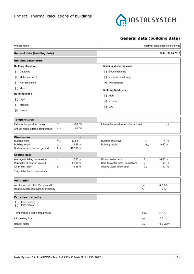
Temperatures
External temperature, design θ'e -20
Annual mean external temperature θm,e 7,6
Internal temperature acc. to standard [ ]
Dimensions
Building width wbld 12,63
Building length lbld 12,89
Surface area of floor on ground Abld 162,81
Number of storeys N 4
Building height hbld
Building parameters
[ ]
Building structure
[X]
[ ]
[ ]
Detached
Multi-apartment
Non-residential
Mixed
Building mass[ ]
[ ]
High
Medium
Building sheltering class
[ ]
[ ]
[X]
Good sheltering
Moderate sheltering
No sheltering
Building tightness
°C
°C
m
m
m2
[−]
m
Air change rate at 50 Pa press. diff. n50 4,0
Heat recuperation system efficiency ηv 0
Extra heat capacity
from building from rooms
Temperature drop(in drop phase)
Init. heating time
Reheat factor
ΔθRH
tRH
fRH
Ground data
Average building depression* z 2,00
Perimeter of floor on ground* P 51,04
Ground water depth T 10,00
Ground water inflow coef. GW 1,00Char. dim. floor* B' 6,38
Corr. factor for temp. fluctuations fg1 1,45
Ventilation
*may differ from room values
m
m
m
m
[−]
[−]
1/h
%
K
h
W/m2
General data (building data) Date: 30.05.2017
[X] Heavy
[X] Medium
[ ] Low
[ ] Light
[ ]
[ ]
???
2,0
0,0
8,60
Project: Thermal calculations of buildings
- 3 -InstalSystem 5 ALPHA-ROOT (Rev. 2.0.A22) © InstalSoft 1996-2017
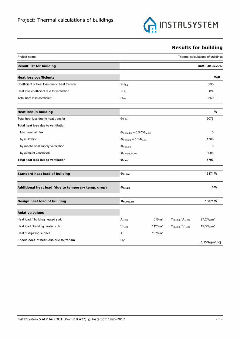
Results for building
Project name: Thermal calculations of buildings
Heat loss in building
Standard heat load of building W
Heat loss coefficients
Coefficient of heat loss due to heat transfer
Relative values
Additional heat load (due to temporary temp. drop) W
Design heat load of building W
Result list for building Date: 30.05.2017
Heat loss coefficient due to ventilation
Total heat loss coefficient
Total heat loss due to heat transfer
Total heat loss due to ventilation
Min. vent. air flux
by infiltration
by mechanical supply ventilation
by exhaust ventilation
Total heat loss due to ventilation
Heat load / building heated surf.
Heat load / building heated cub.
Heat dissipating surface
Specif. coef. of heat loss due to transm.
ΣHT,e
ΣHV
HBld
ΦT,Bld
ΦV,min,Bld = 0,5·ΣΦV,min
ΦV,inf,Bld = ζ·ΣΦV,inf
ΦV,su,Bld
ΦV,mech,inf,Bld
ΦV,Bld
ΦHL,Bld
ΦRH,Bld
ΦHL,Des,Bld
13871
0
13871
4793
3006
0
1788
0
9078
359
124
235
AN,Bld
VN,Bld
A
HT'
510 m²
1123 m³
1978 m²
ΦHL,Bld / AN,Bld W/m²
W/m³
W/(m²·K)
ΦHL,Bld / VN,Bld
27,2
12,3
0,13
W
W/K
Project: Thermal calculations of buildings
- 4 -InstalSystem 5 ALPHA-ROOT (Rev. 2.0.A22) © InstalSoft 1996-2017
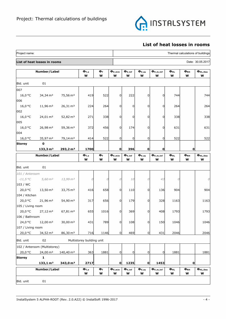
List of heat losses in rooms
Thermal calculations of buildingsProject name:
List of heat losses in rooms Date: 30.05.2017
Number/Label ΦT,e ΦT ΦV,min ΦV,inf ΦV,su ΦV,m,inf ΦHL ΦRH ΦHL,Des
W W W W W W W W W
Bld. unit 01
007
16,0 °C 34,34 m² 75,56 m³ 522 0 744 744419 222 0 0
006
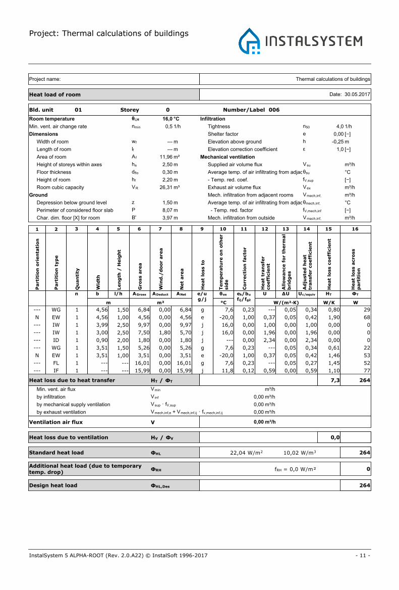
16,0 °C 11,96 m² 26,31 m³ 264 0 264 264224 0 0 0
002
16,0 °C 24,01 m² 52,82 m³ 338 0 338 338271 0 0 0
005
16,0 °C 26,98 m² 59,36 m³ 456 0 631 631372 174 0 0
004
16,0 °C 35,97 m² 79,14 m³ 522 0 522 522414 0 0 0
Storey 0
133,3 m² 293,2 m³ 0 01700 396 0 0
Number/Label ΦT,e ΦT ΦV,min ΦV,inf ΦV,su ΦV,m,inf ΦHL ΦRH ΦHL,Des
W W W W W W W W W
Bld. unit 01
101 / Anteroom
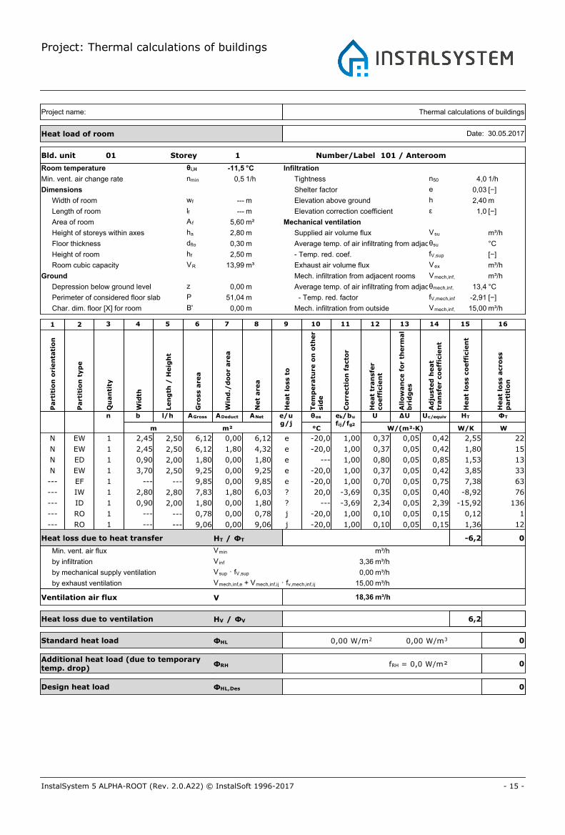
-11,5 °C 5,60 m² 13,99 m³ 0 0 0 00 10 0 43
103 / WC
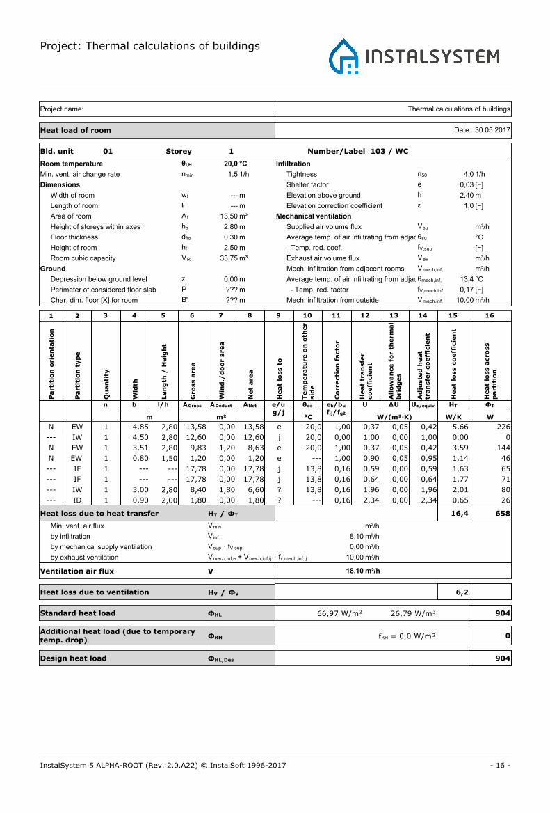
20,0 °C 13,50 m² 33,75 m³ 658 0 904 904416 110 0 136
104 / Kitchen
20,0 °C 21,96 m² 54,90 m³ 656 0 1163 1163317 179 0 328
105 / Living room
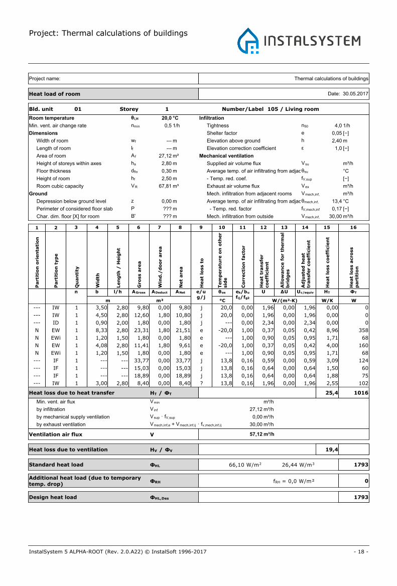
20,0 °C 27,12 m² 67,81 m³ 1016 0 1793 1793655 369 0 408
106 / Bathroom
24,0 °C 12,00 m² 30,00 m³ 789 0 1046 1046431 108 0 150
107 / Living room
20,0 °C 34,52 m² 86,30 m³ 1146 0 2046 2046716 469 0 431
Bld. unit 02 Multistorey building unit
102 / Anteroom (Multistorey)
20,0 °C 24,00 m² 140,40 m³ 1881 0 1881 1881363 0 0 0
Storey 1
133,1 m² 343,0 m³ 0 02717 1235 0 1453
Number/Label ΦT,e ΦT ΦV,min ΦV,inf ΦV,su ΦV,m,inf ΦHL ΦRH ΦHL,Des
W W W W W W W W W
Bld. unit 01
Project: Thermal calculations of buildings
- 5 -InstalSystem 5 ALPHA-ROOT (Rev. 2.0.A22) © InstalSoft 1996-2017
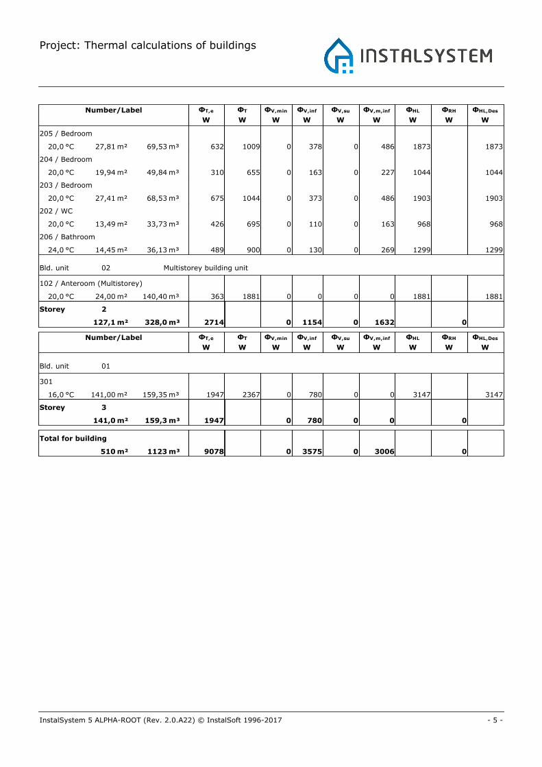
Number/Label ΦT,e ΦT ΦV,min ΦV,inf ΦV,su ΦV,m,inf ΦHL ΦRH ΦHL,Des
W W W W W W W W W
205 / Bedroom
20,0 °C 27,81 m² 69,53 m³ 1009 0 1873 1873632 378 0 486
204 / Bedroom
20,0 °C 19,94 m² 49,84 m³ 655 0 1044 1044310 163 0 227
203 / Bedroom
20,0 °C 27,41 m² 68,53 m³ 1044 0 1903 1903675 373 0 486
202 / WC
20,0 °C 13,49 m² 33,73 m³ 695 0 968 968426 110 0 163
206 / Bathroom
24,0 °C 14,45 m² 36,13 m³ 900 0 1299 1299489 130 0 269
Bld. unit 02 Multistorey building unit
102 / Anteroom (Multistorey)
20,0 °C 24,00 m² 140,40 m³ 1881 0 1881 1881363 0 0 0
Storey 2
127,1 m² 328,0 m³ 0 02714 1154 0 1632
Number/Label ΦT,e ΦT ΦV,min ΦV,inf ΦV,su ΦV,m,inf ΦHL ΦRH ΦHL,Des
W W W W W W W W W
Bld. unit 01
301
16,0 °C 141,00 m² 159,35 m³ 2367 0 3147 31471947 780 0 0
Storey 3
141,0 m² 159,3 m³ 0 01947 780 0 0
Total for building
510 m² 1123 m³ 0 09078 3575 0 3006
Project: Thermal calculations of buildings
- 6 -InstalSystem 5 ALPHA-ROOT (Rev. 2.0.A22) © InstalSoft 1996-2017
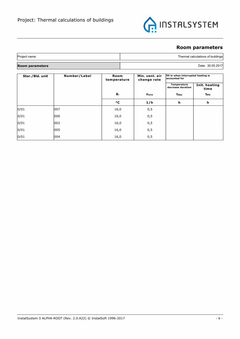
Room parameters
Thermal calculations of buildingsProject name:
Room parameters Date: 30.05.2017
Stor./Bld. unit Number/Label Roomtemperature
Min. vent. airchange rate
Init. heatingtime
Temperaturedecrease duration
fill in when interrupted heating isaccounted for
θi nmin tAbs tRH
°C 1/h h h
16,00/01 0,5007
16,00/01 0,5006
16,00/01 0,5002
16,00/01 0,5005
16,00/01 0,5004
Project: Thermal calculations of buildings
- 7 -InstalSystem 5 ALPHA-ROOT (Rev. 2.0.A22) © InstalSoft 1996-2017
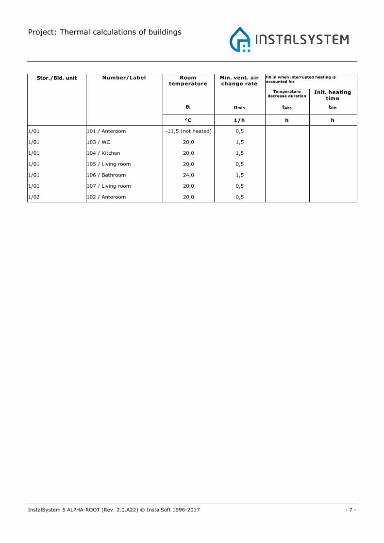
Stor./Bld. unit Number/Label Roomtemperature
Min. vent. airchange rate
Init. heatingtime
Temperaturedecrease duration
fill in when interrupted heating isaccounted for
θi nmin tAbs tRH
°C 1/h h h
-11,5 (not heated)1/01 0,5101 / Anteroom
20,01/01 1,5103 / WC
20,01/01 1,5104 / Kitchen
20,01/01 0,5105 / Living room
24,01/01 1,5106 / Bathroom
20,01/01 0,5107 / Living room
20,01/02 0,5102 / Anteroom
Project: Thermal calculations of buildings
- 8 -InstalSystem 5 ALPHA-ROOT (Rev. 2.0.A22) © InstalSoft 1996-2017
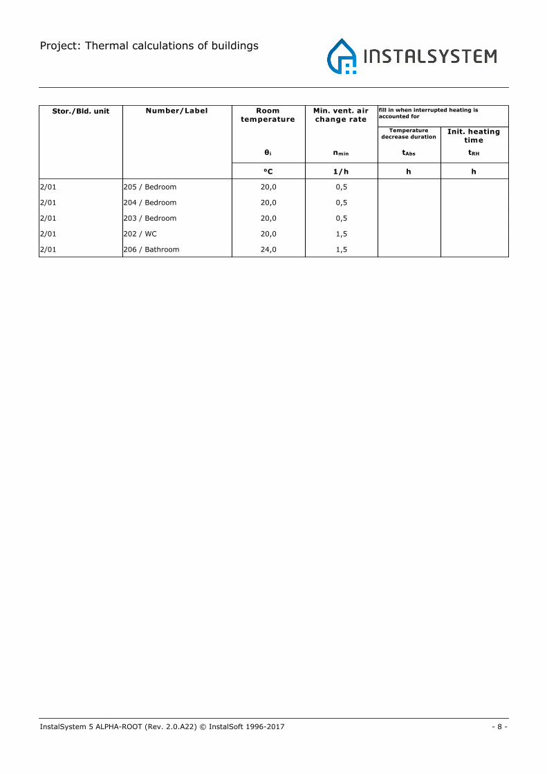
Stor./Bld. unit Number/Label Roomtemperature
Min. vent. airchange rate
Init. heatingtime
Temperaturedecrease duration
fill in when interrupted heating isaccounted for
θi nmin tAbs tRH
°C 1/h h h
20,02/01 0,5205 / Bedroom
20,02/01 0,5204 / Bedroom
20,02/01 0,5203 / Bedroom
20,02/01 1,5202 / WC
24,02/01 1,5206 / Bathroom
Project: Thermal calculations of buildings
- 9 -InstalSystem 5 ALPHA-ROOT (Rev. 2.0.A22) © InstalSoft 1996-2017
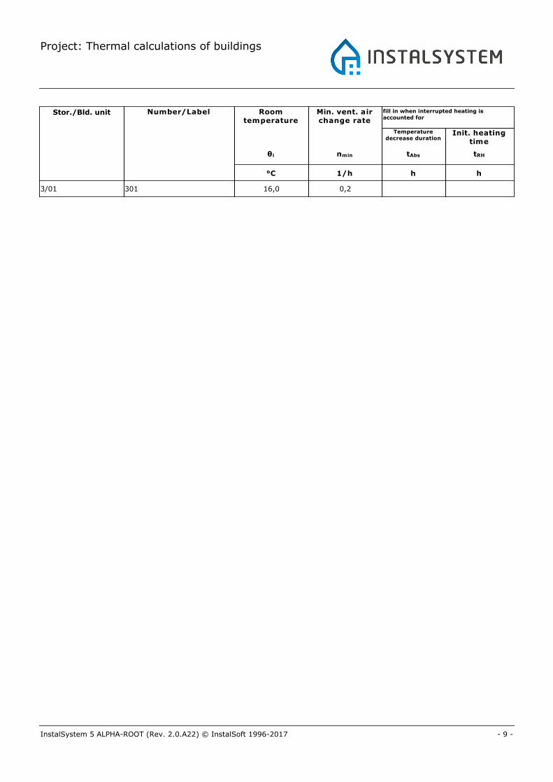
Stor./Bld. unit Number/Label Roomtemperature
Min. vent. airchange rate
Init. heatingtime
Temperaturedecrease duration
fill in when interrupted heating isaccounted for
θi nmin tAbs tRH
°C 1/h h h
16,03/01 0,2301
Project: Thermal calculations of buildings
- 10 -InstalSystem 5 ALPHA-ROOT (Rev. 2.0.A22) © InstalSoft 1996-2017
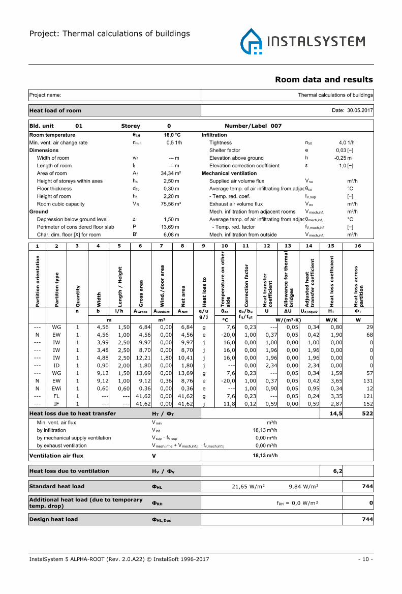
Room data and results
Bld. unit 01 Storey 0 Number/Label 007
Room temperature θi,H 16,0 °C
Min. vent. air change rate nmin 0,5 1/h
Dimensions
Width of room wf --- m
Length of room lf --- m
Area of room A f 34,34 m²
Height of storeys within axes ha 2,50 m
Floor thickness dflo 0,30 m
Height of room hf 2,20 m
Room cubic capacity VR 75,56 m³
Ground
Depression below ground level z 1,50 m
Perimeter of considered floor slab P 13,69 m
Char. dim. floor [X] for room B' 6,08 m
Infiltration
Tightness n50 4,0 1/h
Shelter factor e 0,03 [−]
Elevation above ground h -0,25 m
Elevation correction coefficient ε 1,0 [−]
Mechanical ventilation
Supplied air volume flux Vsu m³/h
Average temp. of air infiltrating from adjacent roomsθsu °C
- Temp. red. coef. fV,sup [−]
Exhaust air volume flux Vex m³/h
Mech. infiltration from adjacent rooms Vmech,inf,ij m³/h
Average temp. of air infiltrating from adjacent roomsθmech,inf, ij °C
- Temp. red. factor fV,mech,inf [−]
Mech. infiltration from outside Vmech,inf,e m³/h
Thermal calculations of buildingsProject name:
Heat load of room Date: 30.05.2017
Part
itio
n o
rien
tati
on
Part
itio
n t
yp
e
Qu
an
tity
Wid
th
Len
gth
/ H
eig
ht
Gro
ss a
rea
Win
d./
do
or
are
a
Net
are
a
Heat
loss t
o
Tem
pera
ture
on
oth
er
sid
e
Co
rrecti
on
facto
r
n b l/h AGross ADeduct ANet e/ug/j
θos
m m² °C
Heat
tran
sfe
rco
eff
icie
nt
ek/bu
fij/fg2
U
W/(m²·K)
All
ow
an
ce f
or
therm
al
bri
dg
es
ΔUA
dju
ste
d h
eat
tran
sfe
r co
eff
icie
nt
Uc/equiv
Heat
loss c
oeff
icie
nt
HT
W/K
Heat
loss a
cro
ss
part
itio
n
ΦT
W
1 2 3 4 5 6 7 8 9 10 11 12 13 14 15 16
--- WG 1 4,56 1,50 6,84 0,00 6,84 g 7,6 0,23 --- 0,05 0,34 0,80 29
N EW 1 4,56 1,00 4,56 0,00 4,56 e -20,0 1,00 0,37 0,05 0,42 1,90 68
--- IW 1 3,99 2,50 9,97 0,00 9,97 j 16,0 0,00 1,00 0,00 1,00 0,00 0
--- IW 1 3,48 2,50 8,70 0,00 8,70 j 16,0 0,00 1,96 0,00 1,96 0,00 0
--- IW 1 4,88 2,50 12,21 1,80 10,41 j 16,0 0,00 1,96 0,00 1,96 0,00 0
--- ID 1 0,90 2,00 1,80 0,00 1,80 j --- 0,00 2,34 0,00 2,34 0,00 0
--- WG 1 9,12 1,50 13,69 0,00 13,69 g 7,6 0,23 --- 0,05 0,34 1,59 57
N EW 1 9,12 1,00 9,12 0,36 8,76 e -20,0 1,00 0,37 0,05 0,42 3,65 131
N EWi 1 0,60 0,60 0,36 0,00 0,36 e --- 1,00 0,90 0,05 0,95 0,34 12
--- FL 1 --- --- 41,62 0,00 41,62 g 7,6 0,23 --- 0,05 0,24 3,35 121
--- IF 1 --- --- 41,62 0,00 41,62 j 11,8 0,12 0,59 0,00 0,59 2,87 152
Heat loss due to heat transfer HT / ΦT 14,5 522
Min. vent. air flux Vmin m³/h
Ventilation air flux V
Heat loss due to ventilation HV / ΦV
Standard heat load ΦHL
Design heat load ΦHL,Des
by infiltration V inf 18,13 m³/h
by mechanical supply ventilation Vsup · fV,sup 0,00 m³/h
by exhaust ventilation Vmech,inf,e + Vmech,inf,ij · fv,mech,inf,ij 0,00
m³/h18,13
6,2
744
7449,84 W/m321,65 W/m2
m³/h
Additional heat load (due to temporarytemp. drop)
ΦRH 0fRH = 0,0 W/m²
Project: Thermal calculations of buildings
- 11 -InstalSystem 5 ALPHA-ROOT (Rev. 2.0.A22) © InstalSoft 1996-2017
Bld. unit 01 Storey 0 Number/Label 006
Room temperature θi,H 16,0 °C
Min. vent. air change rate nmin 0,5 1/h
Dimensions
Width of room wf --- m
Length of room lf --- m
Area of room A f 11,96 m²
Height of storeys within axes ha 2,50 m
Floor thickness dflo 0,30 m
Height of room hf 2,20 m
Room cubic capacity VR 26,31 m³
Ground
Depression below ground level z 1,50 m
Perimeter of considered floor slab P 8,07 m
Char. dim. floor [X] for room B' 3,97 m
Infiltration
Tightness n50 4,0 1/h
Shelter factor e 0,00 [−]
Elevation above ground h -0,25 m
Elevation correction coefficient ε 1,0 [−]
Mechanical ventilation
Supplied air volume flux Vsu m³/h
Average temp. of air infiltrating from adjacent roomsθsu °C
- Temp. red. coef. fV,sup [−]
Exhaust air volume flux Vex m³/h
Mech. infiltration from adjacent rooms Vmech,inf,ij m³/h
Average temp. of air infiltrating from adjacent roomsθmech,inf, ij °C
- Temp. red. factor fV,mech,inf [−]
Mech. infiltration from outside Vmech,inf,e m³/h
Thermal calculations of buildingsProject name:
Heat load of room Date: 30.05.2017
Part
itio
n o
rien
tati
on
Part
itio
n t
yp
e
Qu
an
tity
Wid
th
Len
gth
/ H
eig
ht
Gro
ss a
rea
Win
d./
do
or
are
a
Net
are
a
Heat
loss t
o
Tem
pera
ture
on
oth
er
sid
e
Co
rrecti
on
facto
r
n b l/h AGross ADeduct ANet e/ug/j
θos
m m² °C
Heat
tran
sfe
rco
eff
icie
nt
ek/bu
fij/fg2
U
W/(m²·K)
All
ow
an
ce f
or
therm
al
bri
dg
es
ΔU
Ad
juste
d h
eat
tran
sfe
r co
eff
icie
nt
Uc/equiv
Heat
loss c
oeff
icie
nt
HT
W/K
Heat
loss a
cro
ss
part
itio
n
ΦT
W
1 2 3 4 5 6 7 8 9 10 11 12 13 14 15 16
--- WG 1 4,56 1,50 6,84 0,00 6,84 g 7,6 0,23 --- 0,05 0,34 0,80 29
N EW 1 4,56 1,00 4,56 0,00 4,56 e -20,0 1,00 0,37 0,05 0,42 1,90 68
--- IW 1 3,99 2,50 9,97 0,00 9,97 j 16,0 0,00 1,00 0,00 1,00 0,00 0
--- IW 1 3,00 2,50 7,50 1,80 5,70 j 16,0 0,00 1,96 0,00 1,96 0,00 0
--- ID 1 0,90 2,00 1,80 0,00 1,80 j --- 0,00 2,34 0,00 2,34 0,00 0
--- WG 1 3,51 1,50 5,26 0,00 5,26 g 7,6 0,23 --- 0,05 0,34 0,61 22
N EW 1 3,51 1,00 3,51 0,00 3,51 e -20,0 1,00 0,37 0,05 0,42 1,46 53
--- FL 1 --- --- 16,01 0,00 16,01 g 7,6 0,23 --- 0,05 0,27 1,45 52
--- IF 1 --- --- 15,99 0,00 15,99 j 11,8 0,12 0,59 0,00 0,59 1,10 77
Heat loss due to heat transfer HT / ΦT 7,3 264
Min. vent. air flux Vmin m³/h
Ventilation air flux V
Heat loss due to ventilation HV / ΦV
Standard heat load ΦHL
Design heat load ΦHL,Des
by infiltration V inf 0,00 m³/h
by mechanical supply ventilation Vsup · fV,sup 0,00 m³/h
by exhaust ventilation Vmech,inf,e + Vmech,inf,ij · fv,mech,inf,ij 0,00
m³/h0,00
0,0
264
26410,02 W/m322,04 W/m2
m³/h
Additional heat load (due to temporarytemp. drop)
ΦRH 0fRH = 0,0 W/m²

Project: Thermal calculations of buildings
- 12 -InstalSystem 5 ALPHA-ROOT (Rev. 2.0.A22) © InstalSoft 1996-2017
Bld. unit 01 Storey 0 Number/Label 002
Room temperature θi,H 16,0 °C
Min. vent. air change rate nmin 0,5 1/h
Dimensions
Width of room wf --- m
Length of room lf --- m
Area of room A f 24,01 m²
Height of storeys within axes ha 2,50 m
Floor thickness dflo 0,30 m
Height of room hf 2,20 m
Room cubic capacity VR 52,82 m³
Ground
Depression below ground level z 1,50 m
Perimeter of considered floor slab P 3,25 m
Char. dim. floor [X] for room B' 17,16 m
Infiltration
Tightness n50 4,0 1/h
Shelter factor e 0,00 [−]
Elevation above ground h -0,25 m
Elevation correction coefficient ε 1,0 [−]
Mechanical ventilation
Supplied air volume flux Vsu m³/h
Average temp. of air infiltrating from adjacent roomsθsu °C
- Temp. red. coef. fV,sup [−]
Exhaust air volume flux Vex m³/h
Mech. infiltration from adjacent rooms Vmech,inf,ij m³/h
Average temp. of air infiltrating from adjacent roomsθmech,inf, ij °C
- Temp. red. factor fV,mech,inf [−]
Mech. infiltration from outside Vmech,inf,e m³/h
Thermal calculations of buildingsProject name:
Heat load of room Date: 30.05.2017
Part
itio
n o
rien
tati
on
Part
itio
n t
yp
e
Qu
an
tity
Wid
th
Len
gth
/ H
eig
ht
Gro
ss a
rea
Win
d./
do
or
are
a
Net
are
a
Heat
loss t
o
Tem
pera
ture
on
oth
er
sid
e
Co
rrecti
on
facto
r
n b l/h AGross ADeduct ANet e/ug/j
θos
m m² °C
Heat
tran
sfe
rco
eff
icie
nt
ek/bu
fij/fg2
U
W/(m²·K)
All
ow
an
ce f
or
therm
al
bri
dg
es
ΔU
Ad
juste
d h
eat
tran
sfe
r co
eff
icie
nt
Uc/equiv
Heat
loss c
oeff
icie
nt
HT
W/K
Heat
loss a
cro
ss
part
itio
n
ΦT
W
1 2 3 4 5 6 7 8 9 10 11 12 13 14 15 16
--- IW 1 8,00 2,50 20,01 1,80 18,21 j 16,0 0,00 1,96 0,00 1,96 0,00 0
--- ID 1 0,90 2,00 1,80 0,00 1,80 j --- 0,00 2,34 0,00 2,34 0,00 0
--- IW 1 3,00 2,50 7,50 1,80 5,70 j 16,0 0,00 1,96 0,00 1,96 0,00 0
--- ID 1 0,90 2,00 1,80 0,00 1,80 j --- 0,00 2,34 0,00 2,34 0,00 0
--- WG 1 3,25 1,50 4,88 0,00 4,88 g 7,6 0,23 --- 0,05 0,34 0,57 20
N EW 1 3,25 1,00 3,25 0,00 3,25 e -20,0 1,00 0,37 0,05 0,42 1,35 49
--- IW 1 4,88 2,50 12,21 1,80 10,41 j 16,0 0,00 1,96 0,00 1,96 0,00 0
--- ID 1 0,90 2,00 1,80 0,00 1,80 j --- 0,00 2,34 0,00 2,34 0,00 0
--- IW 1 3,00 2,50 7,50 1,80 5,70 j 16,0 0,00 1,96 0,00 1,96 0,00 0
--- ID 1 0,90 2,00 1,80 0,00 1,80 j --- 0,00 2,34 0,00 2,34 0,00 0
--- FL 1 --- --- 27,90 0,00 27,90 g 7,6 0,23 --- 0,05 0,16 1,55 56
--- RO 1 --- --- 27,14 0,00 27,14 j -20,0 1,00 0,10 0,05 0,15 4,06 146
--- IF 1 --- --- 27,14 0,00 27,14 ? 11,8 0,12 0,59 0,00 0,59 1,87 99
Heat loss due to heat transfer HT / ΦT 9,4 338
Min. vent. air flux Vmin m³/h
Ventilation air flux V
Heat loss due to ventilation HV / ΦV
Standard heat load ΦHL
Design heat load ΦHL,Des
by infiltration V inf 0,00 m³/h
by mechanical supply ventilation Vsup · fV,sup 0,00 m³/h
by exhaust ventilation Vmech,inf,e + Vmech,inf,ij · fv,mech,inf,ij 0,00
m³/h0,00
0,0
338
3386,40 W/m314,09 W/m2
m³/h
Additional heat load (due to temporarytemp. drop)
ΦRH 0fRH = 0,0 W/m²

Project: Thermal calculations of buildings
- 13 -InstalSystem 5 ALPHA-ROOT (Rev. 2.0.A22) © InstalSoft 1996-2017
Bld. unit 01 Storey 0 Number/Label 005
Room temperature θi,H 16,0 °C
Min. vent. air change rate nmin 0,5 1/h
Dimensions
Width of room wf --- m
Length of room lf --- m
Area of room A f 26,98 m²
Height of storeys within axes ha 2,50 m
Floor thickness dflo 0,30 m
Height of room hf 2,20 m
Room cubic capacity VR 59,36 m³
Ground
Depression below ground level z 1,50 m
Perimeter of considered floor slab P 12,38 m
Char. dim. floor [X] for room B' 5,45 m
Infiltration
Tightness n50 4,0 1/h
Shelter factor e 0,03 [−]
Elevation above ground h -0,25 m
Elevation correction coefficient ε 1,0 [−]
Mechanical ventilation
Supplied air volume flux Vsu m³/h
Average temp. of air infiltrating from adjacent roomsθsu °C
- Temp. red. coef. fV,sup [−]
Exhaust air volume flux Vex m³/h
Mech. infiltration from adjacent rooms Vmech,inf,ij m³/h
Average temp. of air infiltrating from adjacent roomsθmech,inf, ij °C
- Temp. red. factor fV,mech,inf [−]
Mech. infiltration from outside Vmech,inf,e m³/h
Thermal calculations of buildingsProject name:
Heat load of room Date: 30.05.2017
Part
itio
n o
rien
tati
on
Part
itio
n t
yp
e
Qu
an
tity
Wid
th
Len
gth
/ H
eig
ht
Gro
ss a
rea
Win
d./
do
or
are
a
Net
are
a
Heat
loss t
o
Tem
pera
ture
on
oth
er
sid
e
Co
rrecti
on
facto
r
n b l/h AGross ADeduct ANet e/ug/j
θos
m m² °C
Heat
tran
sfe
rco
eff
icie
nt
ek/bu
fij/fg2
U
W/(m²·K)
All
ow
an
ce f
or
therm
al
bri
dg
es
ΔU
Ad
juste
d h
eat
tran
sfe
r co
eff
icie
nt
Uc/equiv
Heat
loss c
oeff
icie
nt
HT
W/K
Heat
loss a
cro
ss
part
itio
n
ΦT
W
1 2 3 4 5 6 7 8 9 10 11 12 13 14 15 16
--- WG 1 8,33 1,50 12,49 0,00 12,49 g 7,6 0,23 --- 0,05 0,34 1,45 52
N EW 1 8,33 1,00 8,33 0,36 7,97 e -20,0 1,00 0,37 0,05 0,42 3,32 119
N EWi 1 0,60 0,60 0,36 0,00 0,36 e --- 1,00 0,90 0,05 0,95 0,34 12
--- IW 1 4,50 2,50 11,24 0,00 11,24 j 16,0 0,00 1,96 0,00 1,96 0,00 0
--- IW 1 3,00 2,50 7,50 1,80 5,70 j 16,0 0,00 1,96 0,00 1,96 0,00 0
--- ID 1 0,90 2,00 1,80 0,00 1,80 j --- 0,00 2,34 0,00 2,34 0,00 0
--- WG 1 4,06 1,50 6,09 0,00 6,09 g 7,6 0,23 --- 0,05 0,34 0,71 25
N EW 1 4,06 1,00 4,06 0,00 4,06 e -20,0 1,00 0,37 0,05 0,42 1,69 61
--- IW 1 3,48 2,50 8,70 0,00 8,70 j 16,0 0,00 1,96 0,00 1,96 0,00 0
--- FL 1 --- --- 33,77 0,00 33,77 g 7,6 0,23 --- 0,05 0,25 2,84 102
--- IF 1 --- --- 33,77 0,00 33,77 j 11,8 0,12 0,59 0,00 0,59 2,33 124
Heat loss due to heat transfer HT / ΦT 12,7 456
Min. vent. air flux Vmin m³/h
Ventilation air flux V
Heat loss due to ventilation HV / ΦV
Standard heat load ΦHL
Design heat load ΦHL,Des
by infiltration V inf 14,25 m³/h
by mechanical supply ventilation Vsup · fV,sup 0,00 m³/h
by exhaust ventilation Vmech,inf,e + Vmech,inf,ij · fv,mech,inf,ij 0,00
m³/h14,25
4,8
631
63110,62 W/m323,37 W/m2
m³/h
Additional heat load (due to temporarytemp. drop)
ΦRH 0fRH = 0,0 W/m²

Project: Thermal calculations of buildings
- 14 -InstalSystem 5 ALPHA-ROOT (Rev. 2.0.A22) © InstalSoft 1996-2017
Bld. unit 01 Storey 0 Number/Label 004
Room temperature θi,H 16,0 °C
Min. vent. air change rate nmin 0,5 1/h
Dimensions
Width of room wf --- m
Length of room lf --- m
Area of room A f 35,97 m²
Height of storeys within axes ha 2,50 m
Floor thickness dflo 0,30 m
Height of room hf 2,20 m
Room cubic capacity VR 79,14 m³
Ground
Depression below ground level z 1,50 m
Perimeter of considered floor slab P 13,65 m
Char. dim. floor [X] for room B' 6,38 m
Infiltration
Tightness n50 4,0 1/h
Shelter factor e 0,00 [−]
Elevation above ground h -0,25 m
Elevation correction coefficient ε 1,0 [−]
Mechanical ventilation
Supplied air volume flux Vsu m³/h
Average temp. of air infiltrating from adjacent roomsθsu °C
- Temp. red. coef. fV,sup [−]
Exhaust air volume flux Vex m³/h
Mech. infiltration from adjacent rooms Vmech,inf,ij m³/h
Average temp. of air infiltrating from adjacent roomsθmech,inf, ij °C
- Temp. red. factor fV,mech,inf [−]
Mech. infiltration from outside Vmech,inf,e m³/h
Thermal calculations of buildingsProject name:
Heat load of room Date: 30.05.2017
Part
itio
n o
rien
tati
on
Part
itio
n t
yp
e
Qu
an
tity
Wid
th
Len
gth
/ H
eig
ht
Gro
ss a
rea
Win
d./
do
or
are
a
Net
are
a
Heat
loss t
o
Tem
pera
ture
on
oth
er
sid
e
Co
rrecti
on
facto
r
n b l/h AGross ADeduct ANet e/ug/j
θos
m m² °C
Heat
tran
sfe
rco
eff
icie
nt
ek/bu
fij/fg2
U
W/(m²·K)
All
ow
an
ce f
or
therm
al
bri
dg
es
ΔU
Ad
juste
d h
eat
tran
sfe
r co
eff
icie
nt
Uc/equiv
Heat
loss c
oeff
icie
nt
HT
W/K
Heat
loss a
cro
ss
part
itio
n
ΦT
W
1 2 3 4 5 6 7 8 9 10 11 12 13 14 15 16
--- IW 1 8,00 2,50 20,01 1,80 18,21 j 16,0 0,00 1,96 0,00 1,96 0,00 0
--- ID 1 0,90 2,00 1,80 0,00 1,80 j --- 0,00 2,34 0,00 2,34 0,00 0
--- IW 1 4,50 2,50 11,24 0,00 11,24 j 16,0 0,00 1,96 0,00 1,96 0,00 0
--- WG 1 8,58 1,50 12,86 0,00 12,86 g 7,6 0,23 --- 0,05 0,34 1,49 54
N EW 1 8,58 1,00 8,58 0,00 8,58 e -20,0 1,00 0,37 0,05 0,42 3,57 129
--- WG 1 5,07 1,50 7,61 0,00 7,61 g 7,6 0,23 --- 0,05 0,34 0,88 32
N EW 1 5,07 1,00 5,07 0,00 5,07 e -20,0 1,00 0,37 0,05 0,42 2,11 76
--- FL 1 --- --- 43,51 0,00 43,51 g 7,6 0,23 --- 0,05 0,23 3,44 124
--- IF 1 --- --- 17,78 0,00 17,78 j 11,8 0,12 0,59 0,00 0,59 1,22 65
--- IF 1 --- --- 25,69 0,00 25,69 j 11,8 0,12 0,59 0,00 0,59 1,77 94
Heat loss due to heat transfer HT / ΦT 14,5 522
Min. vent. air flux Vmin m³/h
Ventilation air flux V
Heat loss due to ventilation HV / ΦV
Standard heat load ΦHL
Design heat load ΦHL,Des
by infiltration V inf 0,00 m³/h
by mechanical supply ventilation Vsup · fV,sup 0,00 m³/h
by exhaust ventilation Vmech,inf,e + Vmech,inf,ij · fv,mech,inf,ij 0,00
m³/h0,00
0,0
522
5226,59 W/m314,50 W/m2
m³/h
Additional heat load (due to temporarytemp. drop)
ΦRH 0fRH = 0,0 W/m²
Project: Thermal calculations of buildings
- 15 -InstalSystem 5 ALPHA-ROOT (Rev. 2.0.A22) © InstalSoft 1996-2017
Bld. unit 01 Storey 1 Number/Label 101 / Anteroom
Room temperature θi,H -11,5 °C
Min. vent. air change rate nmin 0,5 1/h
Dimensions
Width of room wf --- m
Length of room lf --- m
Area of room A f 5,60 m²
Height of storeys within axes ha 2,80 m
Floor thickness dflo 0,30 m
Height of room hf 2,50 m
Room cubic capacity VR 13,99 m³
Ground
Depression below ground level z 0,00 m
Perimeter of considered floor slab P 51,04 m
Char. dim. floor [X] for room B' 0,00 m
Infiltration
Tightness n50 4,0 1/h
Shelter factor e 0,03 [−]
Elevation above ground h 2,40 m
Elevation correction coefficient ε 1,0 [−]
Mechanical ventilation
Supplied air volume flux Vsu m³/h
Average temp. of air infiltrating from adjacent roomsθsu °C
- Temp. red. coef. fV,sup [−]
Exhaust air volume flux Vex m³/h
Mech. infiltration from adjacent rooms Vmech,inf,ij m³/h
Average temp. of air infiltrating from adjacent roomsθmech,inf, ij 13,4 °C
- Temp. red. factor fV,mech,inf -2,91 [−]
Mech. infiltration from outside Vmech,inf,e 15,00 m³/h
Thermal calculations of buildingsProject name:
Heat load of room Date: 30.05.2017
Part
itio
n o
rien
tati
on
Part
itio
n t
yp
e
Qu
an
tity
Wid
th
Len
gth
/ H
eig
ht
Gro
ss a
rea
Win
d./
do
or
are
a
Net
are
a
Heat
loss t
o
Tem
pera
ture
on
oth
er
sid
e
Co
rrecti
on
facto
r
n b l/h AGross ADeduct ANet e/ug/j
θos
m m² °C
Heat
tran
sfe
rco
eff
icie
nt
ek/bu
fij/fg2
U
W/(m²·K)
All
ow
an
ce f
or
therm
al
bri
dg
es
ΔU
Ad
juste
d h
eat
tran
sfe
r co
eff
icie
nt
Uc/equiv
Heat
loss c
oeff
icie
nt
HT
W/K
Heat
loss a
cro
ss
part
itio
n
ΦT
W
1 2 3 4 5 6 7 8 9 10 11 12 13 14 15 16
N EW 1 2,45 2,50 6,12 0,00 6,12 e -20,0 1,00 0,37 0,05 0,42 2,55 22
N EW 1 2,45 2,50 6,12 1,80 4,32 e -20,0 1,00 0,37 0,05 0,42 1,80 15
N ED 1 0,90 2,00 1,80 0,00 1,80 e --- 1,00 0,80 0,05 0,85 1,53 13
N EW 1 3,70 2,50 9,25 0,00 9,25 e -20,0 1,00 0,37 0,05 0,42 3,85 33
--- EF 1 --- --- 9,85 0,00 9,85 e -20,0 1,00 0,70 0,05 0,75 7,38 63
--- IW 1 2,80 2,80 7,83 1,80 6,03 ? 20,0 -3,69 0,35 0,05 0,40 -8,92 76
--- ID 1 0,90 2,00 1,80 0,00 1,80 ? --- -3,69 2,34 0,05 2,39 -15,92 136
--- RO 1 --- --- 0,78 0,00 0,78 j -20,0 1,00 0,10 0,05 0,15 0,12 1
--- RO 1 --- --- 9,06 0,00 9,06 j -20,0 1,00 0,10 0,05 0,15 1,36 12
Heat loss due to heat transfer HT / ΦT -6,2 0
Min. vent. air flux Vmin m³/h
Ventilation air flux V
Heat loss due to ventilation HV / ΦV
Standard heat load ΦHL
Design heat load ΦHL,Des
by infiltration V inf 3,36 m³/h
by mechanical supply ventilation Vsup · fV,sup 0,00 m³/h
by exhaust ventilation Vmech,inf,e + Vmech,inf,ij · fv,mech,inf,ij 15,00
m³/h18,36
6,2
0
00,00 W/m30,00 W/m2
m³/h
Additional heat load (due to temporarytemp. drop)
ΦRH 0fRH = 0,0 W/m²
Project: Thermal calculations of buildings
- 16 -InstalSystem 5 ALPHA-ROOT (Rev. 2.0.A22) © InstalSoft 1996-2017
Bld. unit 01 Storey 1 Number/Label 103 / WC
Room temperature θi,H 20,0 °C
Min. vent. air change rate nmin 1,5 1/h
Dimensions
Width of room wf --- m
Length of room lf --- m
Area of room A f 13,50 m²
Height of storeys within axes ha 2,80 m
Floor thickness dflo 0,30 m
Height of room hf 2,50 m
Room cubic capacity VR 33,75 m³
Ground
Depression below ground level z 0,00 m
Perimeter of considered floor slab P ??? m
Char. dim. floor [X] for room B' ??? m
Infiltration
Tightness n50 4,0 1/h
Shelter factor e 0,03 [−]
Elevation above ground h 2,40 m
Elevation correction coefficient ε 1,0 [−]
Mechanical ventilation
Supplied air volume flux Vsu m³/h
Average temp. of air infiltrating from adjacent roomsθsu °C
- Temp. red. coef. fV,sup [−]
Exhaust air volume flux Vex m³/h
Mech. infiltration from adjacent rooms Vmech,inf,ij m³/h
Average temp. of air infiltrating from adjacent roomsθmech,inf, ij 13,4 °C
- Temp. red. factor fV,mech,inf 0,17 [−]
Mech. infiltration from outside Vmech,inf,e 10,00 m³/h
Thermal calculations of buildingsProject name:
Heat load of room Date: 30.05.2017
Part
itio
n o
rien
tati
on
Part
itio
n t
yp
e
Qu
an
tity
Wid
th
Len
gth
/ H
eig
ht
Gro
ss a
rea
Win
d./
do
or
are
a
Net
are
a
Heat
loss t
o
Tem
pera
ture
on
oth
er
sid
e
Co
rrecti
on
facto
r
n b l/h AGross ADeduct ANet e/ug/j
θos
m m² °C
Heat
tran
sfe
rco
eff
icie
nt
ek/bu
fij/fg2
U
W/(m²·K)
All
ow
an
ce f
or
therm
al
bri
dg
es
ΔU
Ad
juste
d h
eat
tran
sfe
r co
eff
icie
nt
Uc/equiv
Heat
loss c
oeff
icie
nt
HT
W/K
Heat
loss a
cro
ss
part
itio
n
ΦT
W
1 2 3 4 5 6 7 8 9 10 11 12 13 14 15 16
N EW 1 4,85 2,80 13,58 0,00 13,58 e -20,0 1,00 0,37 0,05 0,42 5,66 226
--- IW 1 4,50 2,80 12,60 0,00 12,60 j 20,0 0,00 1,00 0,00 1,00 0,00 0
N EW 1 3,51 2,80 9,83 1,20 8,63 e -20,0 1,00 0,37 0,05 0,42 3,59 144
N EWi 1 0,80 1,50 1,20 0,00 1,20 e --- 1,00 0,90 0,05 0,95 1,14 46
--- IF 1 --- --- 17,78 0,00 17,78 j 13,8 0,16 0,59 0,00 0,59 1,63 65
--- IF 1 --- --- 17,78 0,00 17,78 j 13,8 0,16 0,64 0,00 0,64 1,77 71
--- IW 1 3,00 2,80 8,40 1,80 6,60 ? 13,8 0,16 1,96 0,00 1,96 2,01 80
--- ID 1 0,90 2,00 1,80 0,00 1,80 ? --- 0,16 2,34 0,00 2,34 0,65 26
Heat loss due to heat transfer HT / ΦT 16,4 658
Min. vent. air flux Vmin m³/h
Ventilation air flux V
Heat loss due to ventilation HV / ΦV
Standard heat load ΦHL
Design heat load ΦHL,Des
by infiltration V inf 8,10 m³/h
by mechanical supply ventilation Vsup · fV,sup 0,00 m³/h
by exhaust ventilation Vmech,inf,e + Vmech,inf,ij · fv,mech,inf,ij 10,00
m³/h18,10
6,2
904
90426,79 W/m366,97 W/m2
m³/h
Additional heat load (due to temporarytemp. drop)
ΦRH 0fRH = 0,0 W/m²

Project: Thermal calculations of buildings
- 17 -InstalSystem 5 ALPHA-ROOT (Rev. 2.0.A22) © InstalSoft 1996-2017
Bld. unit 01 Storey 1 Number/Label 104 / Kitchen
Room temperature θi,H 20,0 °C
Min. vent. air change rate nmin 1,5 1/h
Dimensions
Width of room wf --- m
Length of room lf --- m
Area of room A f 21,96 m²
Height of storeys within axes ha 2,80 m
Floor thickness dflo 0,30 m
Height of room hf 2,50 m
Room cubic capacity VR 54,90 m³
Ground
Depression below ground level z 0,00 m
Perimeter of considered floor slab P ??? m
Char. dim. floor [X] for room B' ??? m
Infiltration
Tightness n50 4,0 1/h
Shelter factor e 0,03 [−]
Elevation above ground h 2,40 m
Elevation correction coefficient ε 1,0 [−]
Mechanical ventilation
Supplied air volume flux Vsu m³/h
Average temp. of air infiltrating from adjacent roomsθsu °C
- Temp. red. coef. fV,sup [−]
Exhaust air volume flux Vex 70,00 m³/h
Mech. infiltration from adjacent rooms Vmech,inf,ij m³/h
Average temp. of air infiltrating from adjacent roomsθmech,inf, ij 13,4 °C
- Temp. red. factor fV,mech,inf 0,17 [−]
Mech. infiltration from outside Vmech,inf,e 15,00 m³/h
Thermal calculations of buildingsProject name:
Heat load of room Date: 30.05.2017
Part
itio
n o
rien
tati
on
Part
itio
n t
yp
e
Qu
an
tity
Wid
th
Len
gth
/ H
eig
ht
Gro
ss a
rea
Win
d./
do
or
are
a
Net
are
a
Heat
loss t
o
Tem
pera
ture
on
oth
er
sid
e
Co
rrecti
on
facto
r
n b l/h AGross ADeduct ANet e/ug/j
θos
m m² °C
Heat
tran
sfe
rco
eff
icie
nt
ek/bu
fij/fg2
U
W/(m²·K)
All
ow
an
ce f
or
therm
al
bri
dg
es
ΔU
Ad
juste
d h
eat
tran
sfe
r co
eff
icie
nt
Uc/equiv
Heat
loss c
oeff
icie
nt
HT
W/K
Heat
loss a
cro
ss
part
itio
n
ΦT
W
1 2 3 4 5 6 7 8 9 10 11 12 13 14 15 16
--- IW 1 4,50 2,80 12,60 1,80 10,80 j 20,0 0,00 1,96 0,00 1,96 0,00 0
--- ID 1 0,90 2,00 1,80 0,00 1,80 j --- 0,00 2,34 0,00 2,34 0,00 0
--- IW 1 4,50 2,80 12,60 0,00 12,60 j 20,0 0,00 1,00 0,00 1,00 0,00 0
N EW 1 5,07 2,80 14,18 1,80 12,38 e -20,0 1,00 0,37 0,05 0,42 5,16 206
N EWi 1 1,20 1,50 1,80 0,00 1,80 e --- 1,00 0,90 0,05 0,95 1,71 68
--- IF 1 --- --- 25,69 0,00 25,69 j 13,8 0,16 0,59 0,00 0,59 2,35 94
--- RO 1 --- --- 7,01 0,00 7,01 j -20,0 1,00 0,10 0,05 0,15 1,05 42
--- IF 1 --- --- 18,69 0,00 18,69 j 13,8 0,16 0,64 0,00 0,64 1,86 75
--- IW 1 4,88 2,80 13,66 1,80 11,86 ? 13,8 0,16 1,96 0,00 1,96 3,61 144
--- ID 1 0,90 2,00 1,80 0,00 1,80 ? --- 0,16 2,34 0,00 2,34 0,65 26
Heat loss due to heat transfer HT / ΦT 16,4 656
Min. vent. air flux Vmin m³/h
Ventilation air flux V
Heat loss due to ventilation HV / ΦV
Standard heat load ΦHL
Design heat load ΦHL,Des
by infiltration V inf 13,18 m³/h
by mechanical supply ventilation Vsup · fV,sup 0,00 m³/h
by exhaust ventilation Vmech,inf,e + Vmech,inf,ij · fv,mech,inf,ij 24,14
m³/h37,32
12,7
1163
116321,19 W/m352,97 W/m2
m³/h
Additional heat load (due to temporarytemp. drop)
ΦRH 0fRH = 0,0 W/m²
Project: Thermal calculations of buildings
- 18 -InstalSystem 5 ALPHA-ROOT (Rev. 2.0.A22) © InstalSoft 1996-2017
Bld. unit 01 Storey 1 Number/Label 105 / Living room
Room temperature θi,H 20,0 °C
Min. vent. air change rate nmin 0,5 1/h
Dimensions
Width of room wf --- m
Length of room lf --- m
Area of room A f 27,12 m²
Height of storeys within axes ha 2,80 m
Floor thickness dflo 0,30 m
Height of room hf 2,50 m
Room cubic capacity VR 67,81 m³
Ground
Depression below ground level z 0,00 m
Perimeter of considered floor slab P ??? m
Char. dim. floor [X] for room B' ??? m
Infiltration
Tightness n50 4,0 1/h
Shelter factor e 0,05 [−]
Elevation above ground h 2,40 m
Elevation correction coefficient ε 1,0 [−]
Mechanical ventilation
Supplied air volume flux Vsu m³/h
Average temp. of air infiltrating from adjacent roomsθsu °C
- Temp. red. coef. fV,sup [−]
Exhaust air volume flux Vex m³/h
Mech. infiltration from adjacent rooms Vmech,inf,ij m³/h
Average temp. of air infiltrating from adjacent roomsθmech,inf, ij 13,4 °C
- Temp. red. factor fV,mech,inf 0,17 [−]
Mech. infiltration from outside Vmech,inf,e 30,00 m³/h
Thermal calculations of buildingsProject name:
Heat load of room Date: 30.05.2017
Part
itio
n o
rien
tati
on
Part
itio
n t
yp
e
Qu
an
tity
Wid
th
Len
gth
/ H
eig
ht
Gro
ss a
rea
Win
d./
do
or
are
a
Net
are
a
Heat
loss t
o
Tem
pera
ture
on
oth
er
sid
e
Co
rrecti
on
facto
r
n b l/h AGross ADeduct ANet e/ug/j
θos
m m² °C
Heat
tran
sfe
rco
eff
icie
nt
ek/bu
fij/fg2
U
W/(m²·K)
All
ow
an
ce f
or
therm
al
bri
dg
es
ΔU
Ad
juste
d h
eat
tran
sfe
r co
eff
icie
nt
Uc/equiv
Heat
loss c
oeff
icie
nt
HT
W/K
Heat
loss a
cro
ss
part
itio
n
ΦT
W
1 2 3 4 5 6 7 8 9 10 11 12 13 14 15 16
--- IW 1 3,50 2,80 9,80 0,00 9,80 j 20,0 0,00 1,96 0,00 1,96 0,00 0
--- IW 1 4,50 2,80 12,60 1,80 10,80 j 20,0 0,00 1,96 0,00 1,96 0,00 0
--- ID 1 0,90 2,00 1,80 0,00 1,80 j --- 0,00 2,34 0,00 2,34 0,00 0
N EW 1 8,33 2,80 23,31 1,80 21,51 e -20,0 1,00 0,37 0,05 0,42 8,96 358
N EWi 1 1,20 1,50 1,80 0,00 1,80 e --- 1,00 0,90 0,05 0,95 1,71 68
N EW 1 4,08 2,80 11,41 1,80 9,61 e -20,0 1,00 0,37 0,05 0,42 4,00 160
N EWi 1 1,20 1,50 1,80 0,00 1,80 e --- 1,00 0,90 0,05 0,95 1,71 68
--- IF 1 --- --- 33,77 0,00 33,77 j 13,8 0,16 0,59 0,00 0,59 3,09 124
--- IF 1 --- --- 15,03 0,00 15,03 j 13,8 0,16 0,64 0,00 0,64 1,50 60
--- IF 1 --- --- 18,89 0,00 18,89 j 13,8 0,16 0,64 0,00 0,64 1,88 75
--- IW 1 3,00 2,80 8,40 0,00 8,40 ? 13,8 0,16 1,96 0,00 1,96 2,55 102
Heat loss due to heat transfer HT / ΦT 25,4 1016
Min. vent. air flux Vmin m³/h
Ventilation air flux V
Heat loss due to ventilation HV / ΦV
Standard heat load ΦHL
Design heat load ΦHL,Des
by infiltration V inf 27,12 m³/h
by mechanical supply ventilation Vsup · fV,sup 0,00 m³/h
by exhaust ventilation Vmech,inf,e + Vmech,inf,ij · fv,mech,inf,ij 30,00
m³/h57,12
19,4
1793
179326,44 W/m366,10 W/m2
m³/h
Additional heat load (due to temporarytemp. drop)
ΦRH 0fRH = 0,0 W/m²
Project: Thermal calculations of buildings
- 19 -InstalSystem 5 ALPHA-ROOT (Rev. 2.0.A22) © InstalSoft 1996-2017
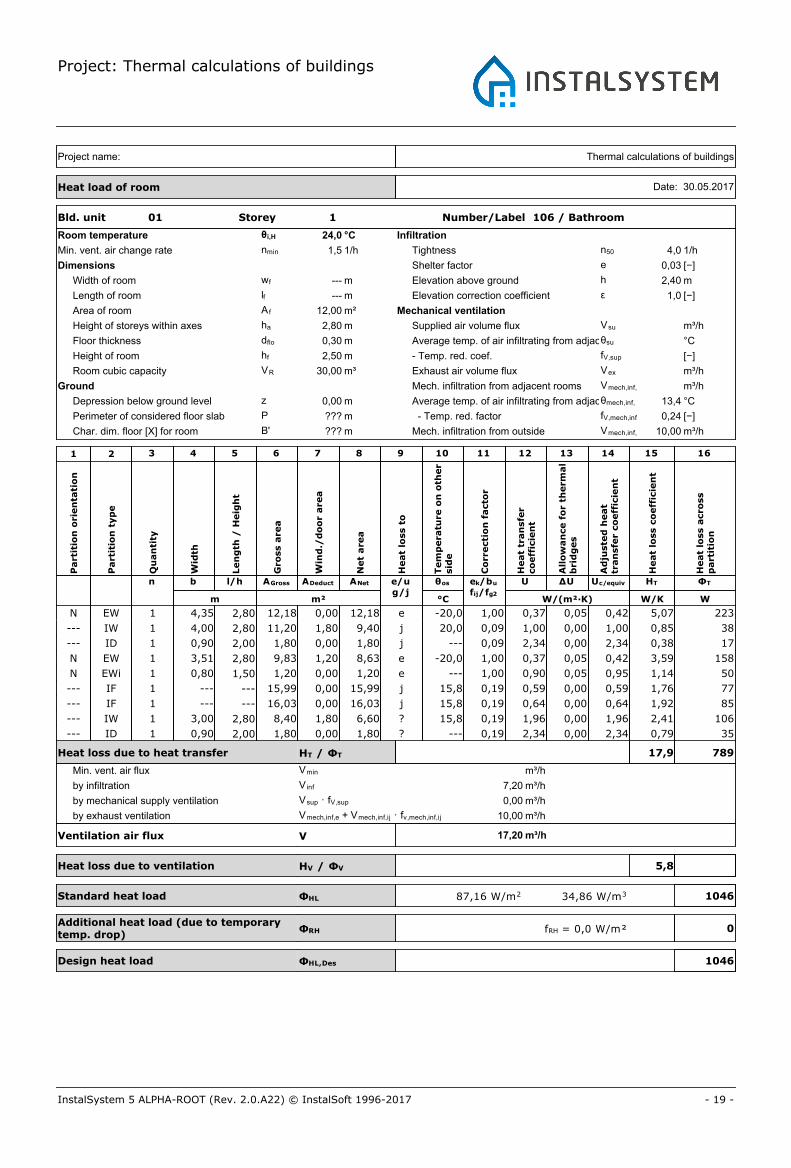
Bld. unit 01 Storey 1 Number/Label 106 / Bathroom
Room temperature θi,H 24,0 °C
Min. vent. air change rate nmin 1,5 1/h
Dimensions
Width of room wf --- m
Length of room lf --- m
Area of room A f 12,00 m²
Height of storeys within axes ha 2,80 m
Floor thickness dflo 0,30 m
Height of room hf 2,50 m
Room cubic capacity VR 30,00 m³
Ground
Depression below ground level z 0,00 m
Perimeter of considered floor slab P ??? m
Char. dim. floor [X] for room B' ??? m
Infiltration
Tightness n50 4,0 1/h
Shelter factor e 0,03 [−]
Elevation above ground h 2,40 m
Elevation correction coefficient ε 1,0 [−]
Mechanical ventilation
Supplied air volume flux Vsu m³/h
Average temp. of air infiltrating from adjacent roomsθsu °C
- Temp. red. coef. fV,sup [−]
Exhaust air volume flux Vex m³/h
Mech. infiltration from adjacent rooms Vmech,inf,ij m³/h
Average temp. of air infiltrating from adjacent roomsθmech,inf, ij 13,4 °C
- Temp. red. factor fV,mech,inf 0,24 [−]
Mech. infiltration from outside Vmech,inf,e 10,00 m³/h
Thermal calculations of buildingsProject name:
Heat load of room Date: 30.05.2017
Part
itio
n o
rien
tati
on
Part
itio
n t
yp
e
Qu
an
tity
Wid
th
Len
gth
/ H
eig
ht
Gro
ss a
rea
Win
d./
do
or
are
a
Net
are
a
Heat
loss t
o
Tem
pera
ture
on
oth
er
sid
e
Co
rrecti
on
facto
r
n b l/h AGross ADeduct ANet e/ug/j
θos
m m² °C
Heat
tran
sfe
rco
eff
icie
nt
ek/bu
fij/fg2
U
W/(m²·K)
All
ow
an
ce f
or
therm
al
bri
dg
es
ΔU
Ad
juste
d h
eat
tran
sfe
r co
eff
icie
nt
Uc/equiv
Heat
loss c
oeff
icie
nt
HT
W/K
Heat
loss a
cro
ss
part
itio
n
ΦT
W
1 2 3 4 5 6 7 8 9 10 11 12 13 14 15 16
N EW 1 4,35 2,80 12,18 0,00 12,18 e -20,0 1,00 0,37 0,05 0,42 5,07 223
--- IW 1 4,00 2,80 11,20 1,80 9,40 j 20,0 0,09 1,00 0,00 1,00 0,85 38
--- ID 1 0,90 2,00 1,80 0,00 1,80 j --- 0,09 2,34 0,00 2,34 0,38 17
N EW 1 3,51 2,80 9,83 1,20 8,63 e -20,0 1,00 0,37 0,05 0,42 3,59 158
N EWi 1 0,80 1,50 1,20 0,00 1,20 e --- 1,00 0,90 0,05 0,95 1,14 50
--- IF 1 --- --- 15,99 0,00 15,99 j 15,8 0,19 0,59 0,00 0,59 1,76 77
--- IF 1 --- --- 16,03 0,00 16,03 j 15,8 0,19 0,64 0,00 0,64 1,92 85
--- IW 1 3,00 2,80 8,40 1,80 6,60 ? 15,8 0,19 1,96 0,00 1,96 2,41 106
--- ID 1 0,90 2,00 1,80 0,00 1,80 ? --- 0,19 2,34 0,00 2,34 0,79 35
Heat loss due to heat transfer HT / ΦT 17,9 789
Min. vent. air flux Vmin m³/h
Ventilation air flux V
Heat loss due to ventilation HV / ΦV
Standard heat load ΦHL
Design heat load ΦHL,Des
by infiltration V inf 7,20 m³/h
by mechanical supply ventilation Vsup · fV,sup 0,00 m³/h
by exhaust ventilation Vmech,inf,e + Vmech,inf,ij · fv,mech,inf,ij 10,00
m³/h17,20
5,8
1046
104634,86 W/m387,16 W/m2
m³/h
Additional heat load (due to temporarytemp. drop)
ΦRH 0fRH = 0,0 W/m²
Project: Thermal calculations of buildings
- 20 -InstalSystem 5 ALPHA-ROOT (Rev. 2.0.A22) © InstalSoft 1996-2017
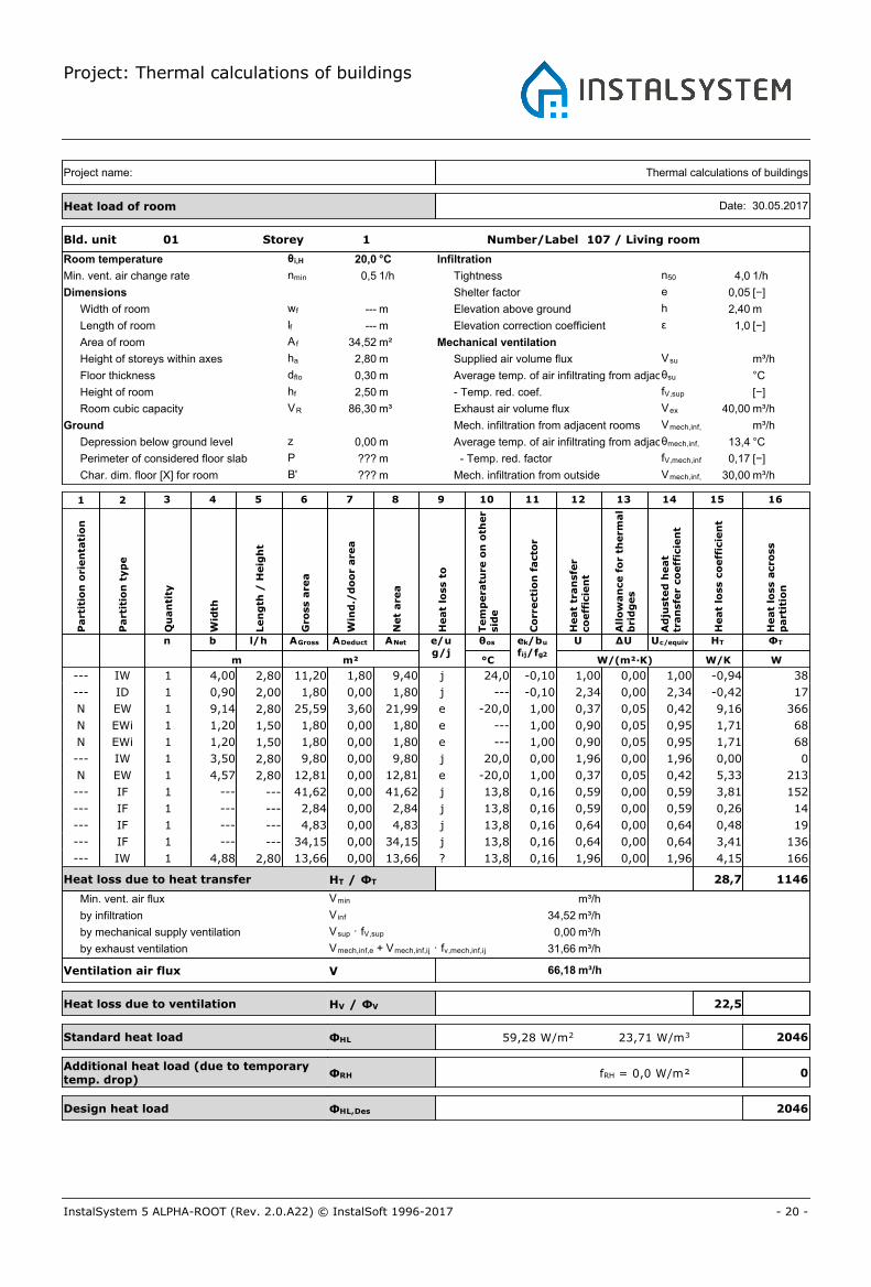
Bld. unit 01 Storey 1 Number/Label 107 / Living room
Room temperature θi,H 20,0 °C
Min. vent. air change rate nmin 0,5 1/h
Dimensions
Width of room wf --- m
Length of room lf --- m
Area of room A f 34,52 m²
Height of storeys within axes ha 2,80 m
Floor thickness dflo 0,30 m
Height of room hf 2,50 m
Room cubic capacity VR 86,30 m³
Ground
Depression below ground level z 0,00 m
Perimeter of considered floor slab P ??? m
Char. dim. floor [X] for room B' ??? m
Infiltration
Tightness n50 4,0 1/h
Shelter factor e 0,05 [−]
Elevation above ground h 2,40 m
Elevation correction coefficient ε 1,0 [−]
Mechanical ventilation
Supplied air volume flux Vsu m³/h
Average temp. of air infiltrating from adjacent roomsθsu °C
- Temp. red. coef. fV,sup [−]
Exhaust air volume flux Vex 40,00 m³/h
Mech. infiltration from adjacent rooms Vmech,inf,ij m³/h
Average temp. of air infiltrating from adjacent roomsθmech,inf, ij 13,4 °C
- Temp. red. factor fV,mech,inf 0,17 [−]
Mech. infiltration from outside Vmech,inf,e 30,00 m³/h
Thermal calculations of buildingsProject name:
Heat load of room Date: 30.05.2017
Part
itio
n o
rien
tati
on
Part
itio
n t
yp
e
Qu
an
tity
Wid
th
Len
gth
/ H
eig
ht
Gro
ss a
rea
Win
d./
do
or
are
a
Net
are
a
Heat
loss t
o
Tem
pera
ture
on
oth
er
sid
e
Co
rrecti
on
facto
r
n b l/h AGross ADeduct ANet e/ug/j
θos
m m² °C
Heat
tran
sfe
rco
eff
icie
nt
ek/bu
fij/fg2
U
W/(m²·K)
All
ow
an
ce f
or
therm
al
bri
dg
es
ΔU
Ad
juste
d h
eat
tran
sfe
r co
eff
icie
nt
Uc/equiv
Heat
loss c
oeff
icie
nt
HT
W/K
Heat
loss a
cro
ss
part
itio
n
ΦT
W
1 2 3 4 5 6 7 8 9 10 11 12 13 14 15 16
--- IW 1 4,00 2,80 11,20 1,80 9,40 j 24,0 -0,10 1,00 0,00 1,00 -0,94 38
--- ID 1 0,90 2,00 1,80 0,00 1,80 j --- -0,10 2,34 0,00 2,34 -0,42 17
N EW 1 9,14 2,80 25,59 3,60 21,99 e -20,0 1,00 0,37 0,05 0,42 9,16 366
N EWi 1 1,20 1,50 1,80 0,00 1,80 e --- 1,00 0,90 0,05 0,95 1,71 68
N EWi 1 1,20 1,50 1,80 0,00 1,80 e --- 1,00 0,90 0,05 0,95 1,71 68
--- IW 1 3,50 2,80 9,80 0,00 9,80 j 20,0 0,00 1,96 0,00 1,96 0,00 0
N EW 1 4,57 2,80 12,81 0,00 12,81 e -20,0 1,00 0,37 0,05 0,42 5,33 213
--- IF 1 --- --- 41,62 0,00 41,62 j 13,8 0,16 0,59 0,00 0,59 3,81 152
--- IF 1 --- --- 2,84 0,00 2,84 j 13,8 0,16 0,59 0,00 0,59 0,26 14
--- IF 1 --- --- 4,83 0,00 4,83 j 13,8 0,16 0,64 0,00 0,64 0,48 19
--- IF 1 --- --- 34,15 0,00 34,15 j 13,8 0,16 0,64 0,00 0,64 3,41 136
--- IW 1 4,88 2,80 13,66 0,00 13,66 ? 13,8 0,16 1,96 0,00 1,96 4,15 166
Heat loss due to heat transfer HT / ΦT 28,7 1146
Min. vent. air flux Vmin m³/h
Ventilation air flux V
Heat loss due to ventilation HV / ΦV
Standard heat load ΦHL
Design heat load ΦHL,Des
by infiltration V inf 34,52 m³/h
by mechanical supply ventilation Vsup · fV,sup 0,00 m³/h
by exhaust ventilation Vmech,inf,e + Vmech,inf,ij · fv,mech,inf,ij 31,66
m³/h66,18
22,5
2046
204623,71 W/m359,28 W/m2
m³/h
Additional heat load (due to temporarytemp. drop)
ΦRH 0fRH = 0,0 W/m²
Project: Thermal calculations of buildings
- 21 -InstalSystem 5 ALPHA-ROOT (Rev. 2.0.A22) © InstalSoft 1996-2017
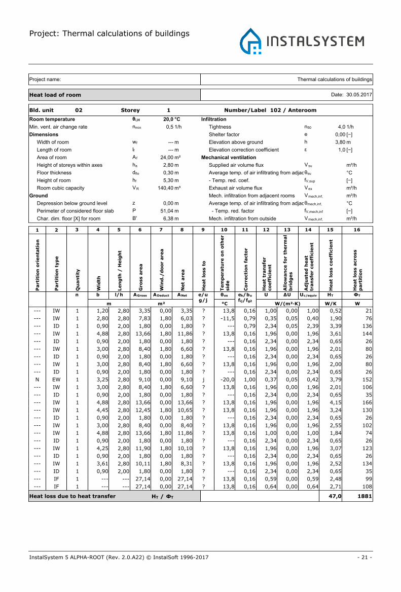
Bld. unit 02 Storey 1 Number/Label 102 / Anteroom
Room temperature θi,H 20,0 °C
Min. vent. air change rate nmin 0,5 1/h
Dimensions
Width of room wf --- m
Length of room lf --- m
Area of room A f 24,00 m²
Height of storeys within axes ha 2,80 m
Floor thickness dflo 0,30 m
Height of room hf 5,30 m
Room cubic capacity VR 140,40 m³
Ground
Depression below ground level z 0,00 m
Perimeter of considered floor slab P 51,04 m
Char. dim. floor [X] for room B' 6,38 m
Infiltration
Tightness n50 4,0 1/h
Shelter factor e 0,00 [−]
Elevation above ground h 3,80 m
Elevation correction coefficient ε 1,0 [−]
Mechanical ventilation
Supplied air volume flux Vsu m³/h
Average temp. of air infiltrating from adjacent roomsθsu °C
- Temp. red. coef. fV,sup [−]
Exhaust air volume flux Vex m³/h
Mech. infiltration from adjacent rooms Vmech,inf,ij m³/h
Average temp. of air infiltrating from adjacent roomsθmech,inf, ij °C
- Temp. red. factor fV,mech,inf [−]
Mech. infiltration from outside Vmech,inf,e m³/h
Thermal calculations of buildingsProject name:
Heat load of room Date: 30.05.2017
Part
itio
n o
rien
tati
on
Part
itio
n t
yp
e
Qu
an
tity
Wid
th
Len
gth
/ H
eig
ht
Gro
ss a
rea
Win
d./
do
or
are
a
Net
are
a
Heat
loss t
o
Tem
pera
ture
on
oth
er
sid
e
Co
rrecti
on
facto
r
n b l/h AGross ADeduct ANet e/ug/j
θos
m m² °C
Heat
tran
sfe
rco
eff
icie
nt
ek/bu
fij/fg2
U
W/(m²·K)
All
ow
an
ce f
or
therm
al
bri
dg
es
ΔU
Ad
juste
d h
eat
tran
sfe
r co
eff
icie
nt
Uc/equiv
Heat
loss c
oeff
icie
nt
HT
W/K
Heat
loss a
cro
ss
part
itio
n
ΦT
W
1 2 3 4 5 6 7 8 9 10 11 12 13 14 15 16
--- IW 1 1,20 2,80 3,35 0,00 3,35 ? 13,8 0,16 1,00 0,00 1,00 0,52 21
--- IW 1 2,80 2,80 7,83 1,80 6,03 ? -11,5 0,79 0,35 0,05 0,40 1,90 76
--- ID 1 0,90 2,00 1,80 0,00 1,80 ? --- 0,79 2,34 0,05 2,39 3,39 136
--- IW 1 4,88 2,80 13,66 1,80 11,86 ? 13,8 0,16 1,96 0,00 1,96 3,61 144
--- ID 1 0,90 2,00 1,80 0,00 1,80 ? --- 0,16 2,34 0,00 2,34 0,65 26
--- IW 1 3,00 2,80 8,40 1,80 6,60 ? 13,8 0,16 1,96 0,00 1,96 2,01 80
--- ID 1 0,90 2,00 1,80 0,00 1,80 ? --- 0,16 2,34 0,00 2,34 0,65 26
--- IW 1 3,00 2,80 8,40 1,80 6,60 ? 13,8 0,16 1,96 0,00 1,96 2,00 80
--- ID 1 0,90 2,00 1,80 0,00 1,80 ? --- 0,16 2,34 0,00 2,34 0,65 26
N EW 1 3,25 2,80 9,10 0,00 9,10 j -20,0 1,00 0,37 0,05 0,42 3,79 152
--- IW 1 3,00 2,80 8,40 1,80 6,60 ? 13,8 0,16 1,96 0,00 1,96 2,01 106
--- ID 1 0,90 2,00 1,80 0,00 1,80 ? --- 0,16 2,34 0,00 2,34 0,65 35
--- IW 1 4,88 2,80 13,66 0,00 13,66 ? 13,8 0,16 1,96 0,00 1,96 4,15 166
--- IW 1 4,45 2,80 12,45 1,80 10,65 ? 13,8 0,16 1,96 0,00 1,96 3,24 130
--- ID 1 0,90 2,00 1,80 0,00 1,80 ? --- 0,16 2,34 0,00 2,34 0,65 26
--- IW 1 3,00 2,80 8,40 0,00 8,40 ? 13,8 0,16 1,96 0,00 1,96 2,55 102
--- IW 1 4,88 2,80 13,66 1,80 11,86 ? 13,8 0,16 1,00 0,00 1,00 1,84 74
--- ID 1 0,90 2,00 1,80 0,00 1,80 ? --- 0,16 2,34 0,00 2,34 0,65 26
--- IW 1 4,25 2,80 11,90 1,80 10,10 ? 13,8 0,16 1,96 0,00 1,96 3,07 123
--- ID 1 0,90 2,00 1,80 0,00 1,80 ? --- 0,16 2,34 0,00 2,34 0,65 26
--- IW 1 3,61 2,80 10,11 1,80 8,31 ? 13,8 0,16 1,96 0,00 1,96 2,52 134
--- ID 1 0,90 2,00 1,80 0,00 1,80 ? --- 0,16 2,34 0,00 2,34 0,65 35
--- IF 1 --- --- 27,14 0,00 27,14 ? 13,8 0,16 0,59 0,00 0,59 2,48 99
--- IF 1 --- --- 27,14 0,00 27,14 ? 13,8 0,16 0,64 0,00 0,64 2,71 108
Heat loss due to heat transfer HT / ΦT 47,0 1881
Project: Thermal calculations of buildings
- 22 -InstalSystem 5 ALPHA-ROOT (Rev. 2.0.A22) © InstalSoft 1996-2017
Part
itio
n o
rien
tati
on
Part
itio
n t
yp
e
Qu
an
tity
Wid
th
Len
gth
/ H
eig
ht
Gro
ss a
rea
Win
d./
do
or
are
a
Net
are
a
Heat
loss t
o
Tem
pera
ture
on
oth
er
sid
e
Co
rrecti
on
facto
r
n b l/h AGross ADeduct ANet e/ug/j
θos
m m² °C
Heat
tran
sfe
rco
eff
icie
nt
ek/bu
fij/fg2
U
W/(m²·K)
All
ow
an
ce f
or
therm
al
bri
dg
es
ΔU
Ad
juste
d h
eat
tran
sfe
r co
eff
icie
nt
Uc/equiv
Heat
loss c
oeff
icie
nt
HT
W/K
Heat
loss a
cro
ss
part
itio
n
ΦT
W
1 2 3 4 5 6 7 8 9 10 11 12 13 14 15 16
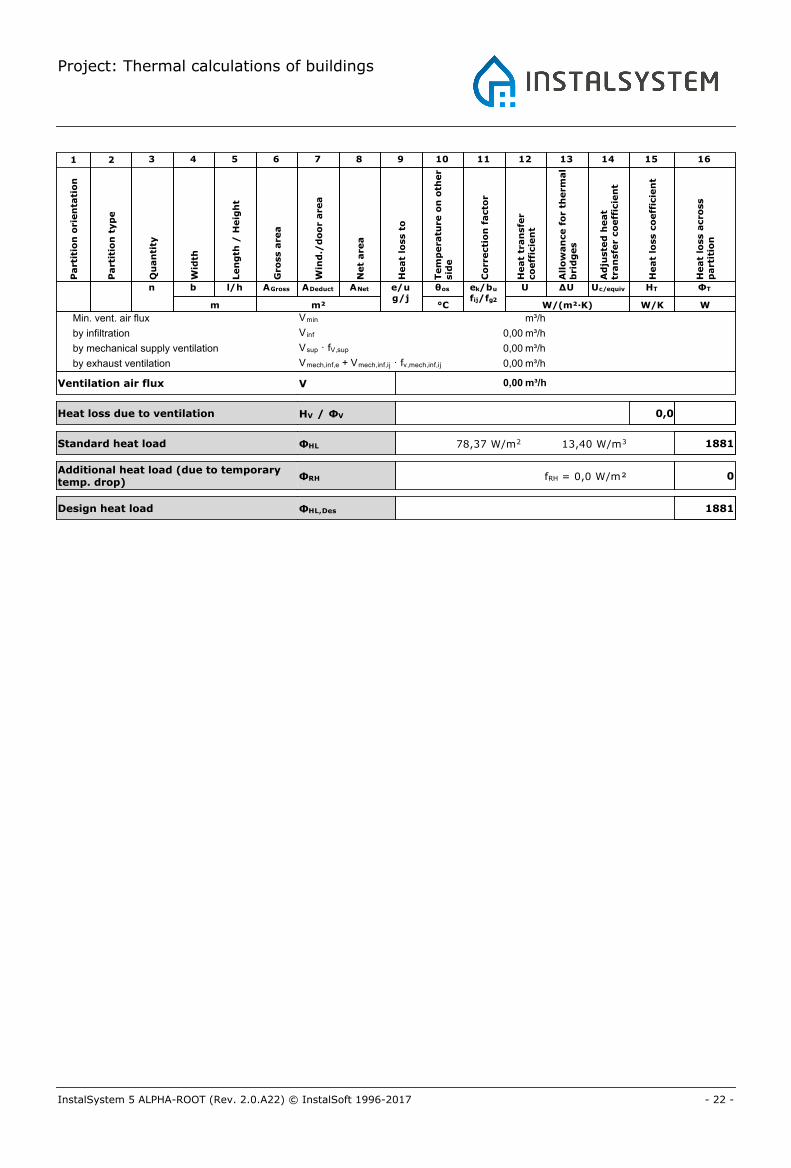
Min. vent. air flux Vmin m³/h
Ventilation air flux V
Heat loss due to ventilation HV / ΦV
Standard heat load ΦHL
Design heat load ΦHL,Des
by infiltration V inf 0,00 m³/h
by mechanical supply ventilation Vsup · fV,sup 0,00 m³/h
by exhaust ventilation Vmech,inf,e + Vmech,inf,ij · fv,mech,inf,ij 0,00
m³/h0,00
0,0
1881
188113,40 W/m378,37 W/m2
m³/h
Additional heat load (due to temporarytemp. drop)
ΦRH 0fRH = 0,0 W/m²
Project: Thermal calculations of buildings
- 23 -InstalSystem 5 ALPHA-ROOT (Rev. 2.0.A22) © InstalSoft 1996-2017
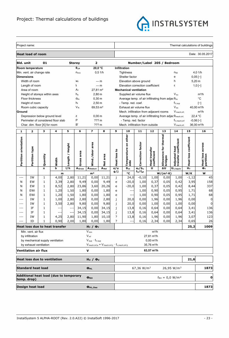
Bld. unit 01 Storey 2 Number/Label 205 / Bedroom
Room temperature θi,H 20,0 °C
Min. vent. air change rate nmin 0,5 1/h
Dimensions
Width of room wf --- m
Length of room lf --- m
Area of room A f 27,81 m²
Height of storeys within axes ha 2,80 m
Floor thickness dflo 0,30 m
Height of room hf 2,50 m
Room cubic capacity VR 69,53 m³
Ground
Depression below ground level z 0,00 m
Perimeter of considered floor slab P ??? m
Char. dim. floor [X] for room B' ??? m
Infiltration
Tightness n50 4,0 1/h
Shelter factor e 0,05 [−]
Elevation above ground h 5,20 m
Elevation correction coefficient ε 1,0 [−]
Mechanical ventilation
Supplied air volume flux Vsu m³/h
Average temp. of air infiltrating from adjacent roomsθsu °C
- Temp. red. coef. fV,sup [−]
Exhaust air volume flux Vex 40,00 m³/h
Mech. infiltration from adjacent rooms Vmech,inf,ij m³/h
Average temp. of air infiltrating from adjacent roomsθmech,inf, ij 22,4 °C
- Temp. red. factor fV,mech,inf -0,06 [−]
Mech. infiltration from outside Vmech,inf,e 36,00 m³/h
Thermal calculations of buildingsProject name:
Heat load of room Date: 30.05.2017
Part
itio
n o
rien
tati
on
Part
itio
n t
yp
e
Qu
an
tity
Wid
th
Len
gth
/ H
eig
ht
Gro
ss a
rea
Win
d./
do
or
are
a
Net
are
a
Heat
loss t
o
Tem
pera
ture
on
oth
er
sid
e
Co
rrecti
on
facto
r
n b l/h AGross ADeduct ANet e/ug/j
θos
m m² °C
Heat
tran
sfe
rco
eff
icie
nt
ek/bu
fij/fg2
U
W/(m²·K)
All
ow
an
ce f
or
therm
al
bri
dg
es
ΔU
Ad
juste
d h
eat
tran
sfe
r co
eff
icie
nt
Uc/equiv
Heat
loss c
oeff
icie
nt
HT
W/K
Heat
loss a
cro
ss
part
itio
n
ΦT
W
1 2 3 4 5 6 7 8 9 10 11 12 13 14 15 16
--- IW 1 4,00 2,80 11,21 0,00 11,21 j 24,0 -0,10 1,00 0,00 1,00 -1,12 45
N EW 1 3,39 2,80 9,49 0,00 9,49 e -20,0 1,00 0,37 0,05 0,42 3,95 158
N EW 1 8,52 2,80 23,86 3,60 20,26 e -20,0 1,00 0,37 0,05 0,42 8,44 337
N EWi 1 1,20 1,50 1,80 0,00 1,80 e --- 1,00 0,90 0,05 0,95 1,71 68
N EWi 1 1,20 1,50 1,80 0,00 1,80 e --- 1,00 0,90 0,05 0,95 1,71 68
--- IW 1 1,00 2,80 2,80 0,00 2,80 j 20,0 0,00 1,96 0,00 1,96 0,00 0
--- IW 1 3,50 2,80 9,80 0,00 9,80 j 20,0 0,00 1,00 0,00 1,00 0,00 0
--- IF 1 --- --- 34,15 0,00 34,15 j 13,8 0,16 0,64 0,00 0,64 3,41 136
--- IF 1 --- --- 34,15 0,00 34,15 j 13,8 0,16 0,64 0,00 0,64 3,41 136
--- IW 1 4,25 2,80 11,90 1,80 10,10 ? 13,8 0,16 1,96 0,00 1,96 3,07 123
--- ID 1 0,90 2,00 1,80 0,00 1,80 ? --- 0,16 2,34 0,00 2,34 0,65 26
Heat loss due to heat transfer HT / ΦT 25,2 1009
Min. vent. air flux Vmin m³/h
Ventilation air flux V
Heat loss due to ventilation HV / ΦV
Standard heat load ΦHL
Design heat load ΦHL,Des
by infiltration V inf 27,81 m³/h
by mechanical supply ventilation Vsup · fV,sup 0,00 m³/h
by exhaust ventilation Vmech,inf,e + Vmech,inf,ij · fv,mech,inf,ij 35,76
m³/h63,57
21,6
1873
187326,95 W/m367,36 W/m2
m³/h
Additional heat load (due to temporarytemp. drop)
ΦRH 0fRH = 0,0 W/m²
Project: Thermal calculations of buildings
- 24 -InstalSystem 5 ALPHA-ROOT (Rev. 2.0.A22) © InstalSoft 1996-2017
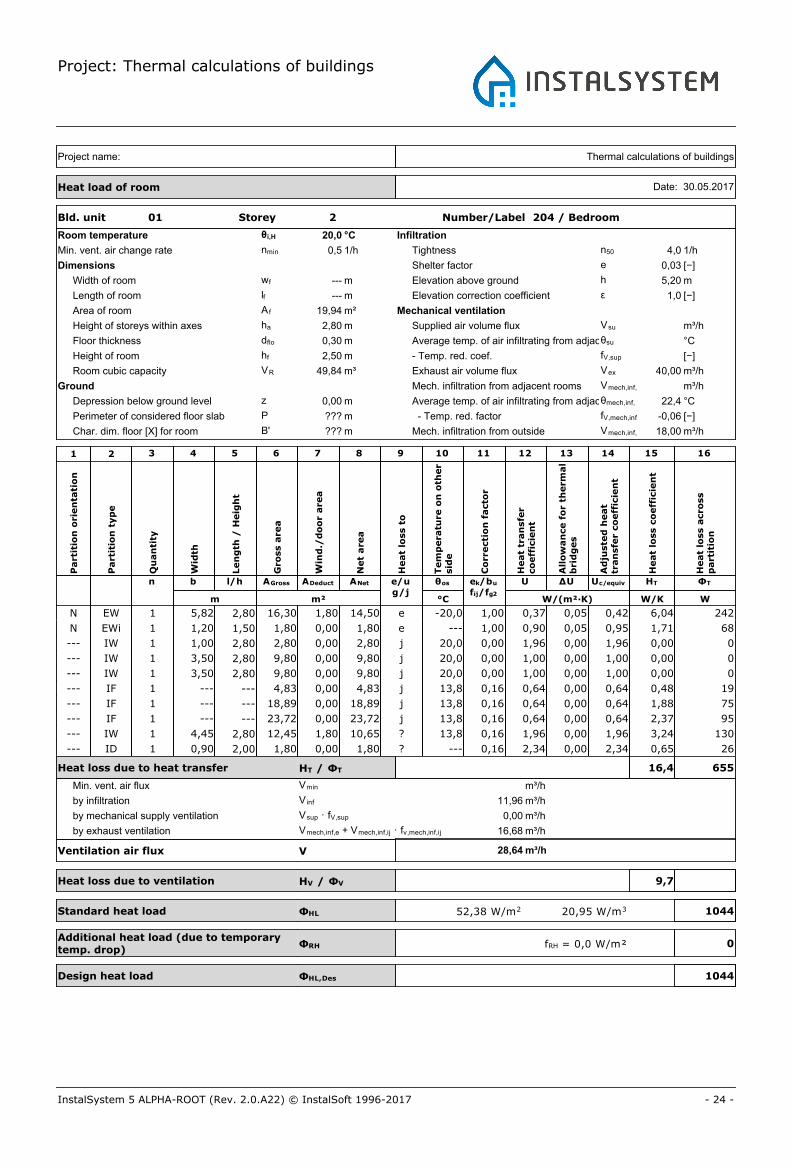
Bld. unit 01 Storey 2 Number/Label 204 / Bedroom
Room temperature θi,H 20,0 °C
Min. vent. air change rate nmin 0,5 1/h
Dimensions
Width of room wf --- m
Length of room lf --- m
Area of room A f 19,94 m²
Height of storeys within axes ha 2,80 m
Floor thickness dflo 0,30 m
Height of room hf 2,50 m
Room cubic capacity VR 49,84 m³
Ground
Depression below ground level z 0,00 m
Perimeter of considered floor slab P ??? m
Char. dim. floor [X] for room B' ??? m
Infiltration
Tightness n50 4,0 1/h
Shelter factor e 0,03 [−]
Elevation above ground h 5,20 m
Elevation correction coefficient ε 1,0 [−]
Mechanical ventilation
Supplied air volume flux Vsu m³/h
Average temp. of air infiltrating from adjacent roomsθsu °C
- Temp. red. coef. fV,sup [−]
Exhaust air volume flux Vex 40,00 m³/h
Mech. infiltration from adjacent rooms Vmech,inf,ij m³/h
Average temp. of air infiltrating from adjacent roomsθmech,inf, ij 22,4 °C
- Temp. red. factor fV,mech,inf -0,06 [−]
Mech. infiltration from outside Vmech,inf,e 18,00 m³/h
Thermal calculations of buildingsProject name:
Heat load of room Date: 30.05.2017
Part
itio
n o
rien
tati
on
Part
itio
n t
yp
e
Qu
an
tity
Wid
th
Len
gth
/ H
eig
ht
Gro
ss a
rea
Win
d./
do
or
are
a
Net
are
a
Heat
loss t
o
Tem
pera
ture
on
oth
er
sid
e
Co
rrecti
on
facto
r
n b l/h AGross ADeduct ANet e/ug/j
θos
m m² °C
Heat
tran
sfe
rco
eff
icie
nt
ek/bu
fij/fg2
U
W/(m²·K)
All
ow
an
ce f
or
therm
al
bri
dg
es
ΔU
Ad
juste
d h
eat
tran
sfe
r co
eff
icie
nt
Uc/equiv
Heat
loss c
oeff
icie
nt
HT
W/K
Heat
loss a
cro
ss
part
itio
n
ΦT
W
1 2 3 4 5 6 7 8 9 10 11 12 13 14 15 16
N EW 1 5,82 2,80 16,30 1,80 14,50 e -20,0 1,00 0,37 0,05 0,42 6,04 242
N EWi 1 1,20 1,50 1,80 0,00 1,80 e --- 1,00 0,90 0,05 0,95 1,71 68
--- IW 1 1,00 2,80 2,80 0,00 2,80 j 20,0 0,00 1,96 0,00 1,96 0,00 0
--- IW 1 3,50 2,80 9,80 0,00 9,80 j 20,0 0,00 1,00 0,00 1,00 0,00 0
--- IW 1 3,50 2,80 9,80 0,00 9,80 j 20,0 0,00 1,00 0,00 1,00 0,00 0
--- IF 1 --- --- 4,83 0,00 4,83 j 13,8 0,16 0,64 0,00 0,64 0,48 19
--- IF 1 --- --- 18,89 0,00 18,89 j 13,8 0,16 0,64 0,00 0,64 1,88 75
--- IF 1 --- --- 23,72 0,00 23,72 j 13,8 0,16 0,64 0,00 0,64 2,37 95
--- IW 1 4,45 2,80 12,45 1,80 10,65 ? 13,8 0,16 1,96 0,00 1,96 3,24 130
--- ID 1 0,90 2,00 1,80 0,00 1,80 ? --- 0,16 2,34 0,00 2,34 0,65 26
Heat loss due to heat transfer HT / ΦT 16,4 655
Min. vent. air flux Vmin m³/h
Ventilation air flux V
Heat loss due to ventilation HV / ΦV
Standard heat load ΦHL
Design heat load ΦHL,Des
by infiltration V inf 11,96 m³/h
by mechanical supply ventilation Vsup · fV,sup 0,00 m³/h
by exhaust ventilation Vmech,inf,e + Vmech,inf,ij · fv,mech,inf,ij 16,68
m³/h28,64
9,7
1044
104420,95 W/m352,38 W/m2
m³/h
Additional heat load (due to temporarytemp. drop)
ΦRH 0fRH = 0,0 W/m²

Project: Thermal calculations of buildings
- 25 -InstalSystem 5 ALPHA-ROOT (Rev. 2.0.A22) © InstalSoft 1996-2017
Bld. unit 01 Storey 2 Number/Label 203 / Bedroom
Room temperature θi,H 20,0 °C
Min. vent. air change rate nmin 0,5 1/h
Dimensions
Width of room wf --- m
Length of room lf --- m
Area of room A f 27,41 m²
Height of storeys within axes ha 2,80 m
Floor thickness dflo 0,30 m
Height of room hf 2,50 m
Room cubic capacity VR 68,53 m³
Ground
Depression below ground level z 0,00 m
Perimeter of considered floor slab P ??? m
Char. dim. floor [X] for room B' ??? m
Infiltration
Tightness n50 4,0 1/h
Shelter factor e 0,05 [−]
Elevation above ground h 5,20 m
Elevation correction coefficient ε 1,0 [−]
Mechanical ventilation
Supplied air volume flux Vsu m³/h
Average temp. of air infiltrating from adjacent roomsθsu °C
- Temp. red. coef. fV,sup [−]
Exhaust air volume flux Vex 40,00 m³/h
Mech. infiltration from adjacent rooms Vmech,inf,ij m³/h
Average temp. of air infiltrating from adjacent roomsθmech,inf, ij 22,4 °C
- Temp. red. factor fV,mech,inf -0,06 [−]
Mech. infiltration from outside Vmech,inf,e 36,00 m³/h
Thermal calculations of buildingsProject name:
Heat load of room Date: 30.05.2017
Part
itio
n o
rien
tati
on
Part
itio
n t
yp
e
Qu
an
tity
Wid
th
Len
gth
/ H
eig
ht
Gro
ss a
rea
Win
d./
do
or
are
a
Net
are
a
Heat
loss t
o
Tem
pera
ture
on
oth
er
sid
e
Co
rrecti
on
facto
r
n b l/h AGross ADeduct ANet e/ug/j
θos
m m² °C
Heat
tran
sfe
rco
eff
icie
nt
ek/bu
fij/fg2
U
W/(m²·K)
All
ow
an
ce f
or
therm
al
bri
dg
es
ΔU
Ad
juste
d h
eat
tran
sfe
r co
eff
icie
nt
Uc/equiv
Heat
loss c
oeff
icie
nt
HT
W/K
Heat
loss a
cro
ss
part
itio
n
ΦT
W
1 2 3 4 5 6 7 8 9 10 11 12 13 14 15 16
--- IW 1 3,18 2,80 8,90 0,00 8,90 j 20,0 0,00 1,00 0,00 1,00 0,00 0
N EW 1 3,69 2,80 10,33 0,00 10,33 e -20,0 1,00 0,37 0,05 0,42 4,30 172
N EW 1 9,14 2,80 25,59 3,60 21,99 e -20,0 1,00 0,37 0,05 0,42 9,16 366
N EWi 1 1,20 1,50 1,80 0,00 1,80 e --- 1,00 0,90 0,05 0,95 1,71 68
N EWi 1 1,20 1,50 1,80 0,00 1,80 e --- 1,00 0,90 0,05 0,95 1,71 68
--- IW 1 3,50 2,80 9,80 0,00 9,80 j 20,0 0,00 1,00 0,00 1,00 0,00 0
--- IF 1 --- --- 15,03 0,00 15,03 j 13,8 0,16 0,64 0,00 0,64 1,50 60
--- IF 1 --- --- 18,69 0,00 18,69 j 13,8 0,16 0,64 0,00 0,64 1,86 75
--- IF 1 --- --- 33,72 0,00 33,72 j 13,8 0,16 0,64 0,00 0,64 3,36 135
--- IW 1 4,88 2,80 13,66 1,80 11,86 ? 13,8 0,16 1,00 0,00 1,00 1,84 74
--- ID 1 0,90 2,00 1,80 0,00 1,80 ? --- 0,16 2,34 0,00 2,34 0,65 26
Heat loss due to heat transfer HT / ΦT 26,1 1044
Min. vent. air flux Vmin m³/h
Ventilation air flux V
Heat loss due to ventilation HV / ΦV
Standard heat load ΦHL
Design heat load ΦHL,Des
by infiltration V inf 27,41 m³/h
by mechanical supply ventilation Vsup · fV,sup 0,00 m³/h
by exhaust ventilation Vmech,inf,e + Vmech,inf,ij · fv,mech,inf,ij 35,76
m³/h63,17
21,5
1903
190327,77 W/m369,42 W/m2
m³/h
Additional heat load (due to temporarytemp. drop)
ΦRH 0fRH = 0,0 W/m²

Project: Thermal calculations of buildings
- 26 -InstalSystem 5 ALPHA-ROOT (Rev. 2.0.A22) © InstalSoft 1996-2017
Bld. unit 01 Storey 2 Number/Label 202 / WC
Room temperature θi,H 20,0 °C
Min. vent. air change rate nmin 1,5 1/h
Dimensions
Width of room wf --- m
Length of room lf --- m
Area of room A f 13,49 m²
Height of storeys within axes ha 2,80 m
Floor thickness dflo 0,30 m
Height of room hf 2,50 m
Room cubic capacity VR 33,73 m³
Ground
Depression below ground level z 0,00 m
Perimeter of considered floor slab P ??? m
Char. dim. floor [X] for room B' ??? m
Infiltration
Tightness n50 4,0 1/h
Shelter factor e 0,03 [−]
Elevation above ground h 5,20 m
Elevation correction coefficient ε 1,0 [−]
Mechanical ventilation
Supplied air volume flux Vsu m³/h
Average temp. of air infiltrating from adjacent roomsθsu °C
- Temp. red. coef. fV,sup [−]
Exhaust air volume flux Vex m³/h
Mech. infiltration from adjacent rooms Vmech,inf,ij m³/h
Average temp. of air infiltrating from adjacent roomsθmech,inf, ij 22,4 °C
- Temp. red. factor fV,mech,inf -0,06 [−]
Mech. infiltration from outside Vmech,inf,e 12,00 m³/h
Thermal calculations of buildingsProject name:
Heat load of room Date: 30.05.2017
Part
itio
n o
rien
tati
on
Part
itio
n t
yp
e
Qu
an
tity
Wid
th
Len
gth
/ H
eig
ht
Gro
ss a
rea
Win
d./
do
or
are
a
Net
are
a
Heat
loss t
o
Tem
pera
ture
on
oth
er
sid
e
Co
rrecti
on
facto
r
n b l/h AGross ADeduct ANet e/ug/j
θos
m m² °C
Heat
tran
sfe
rco
eff
icie
nt
ek/bu
fij/fg2
U
W/(m²·K)
All
ow
an
ce f
or
therm
al
bri
dg
es
ΔU
Ad
juste
d h
eat
tran
sfe
r co
eff
icie
nt
Uc/equiv
Heat
loss c
oeff
icie
nt
HT
W/K
Heat
loss a
cro
ss
part
itio
n
ΦT
W
1 2 3 4 5 6 7 8 9 10 11 12 13 14 15 16
--- IW 1 3,18 2,80 8,90 0,00 8,90 j 20,0 0,00 1,00 0,00 1,00 0,00 0
N EW 1 5,07 2,80 14,21 0,00 14,21 e -20,0 1,00 0,37 0,05 0,42 5,92 237
N EW 1 3,51 2,80 9,83 1,20 8,63 e -20,0 1,00 0,37 0,05 0,42 3,59 144
N EWi 1 0,80 1,50 1,20 0,00 1,20 e --- 1,00 0,90 0,05 0,95 1,14 46
--- IF 1 --- --- 17,78 0,00 17,78 j 13,8 0,16 0,64 0,00 0,64 1,77 71
--- IF 1 --- --- 17,81 0,00 17,81 j 13,8 0,16 0,64 0,00 0,64 1,78 71
--- IW 1 1,20 2,80 3,35 0,00 3,35 ? 13,8 0,16 1,00 0,00 1,00 0,52 21
--- IW 1 3,00 2,80 8,40 1,80 6,60 ? 13,8 0,16 1,96 0,00 1,96 2,00 80
--- ID 1 0,90 2,00 1,80 0,00 1,80 ? --- 0,16 2,34 0,00 2,34 0,65 26
Heat loss due to heat transfer HT / ΦT 17,4 695
Min. vent. air flux Vmin m³/h
Ventilation air flux V
Heat loss due to ventilation HV / ΦV
Standard heat load ΦHL
Design heat load ΦHL,Des
by infiltration V inf 8,09 m³/h
by mechanical supply ventilation Vsup · fV,sup 0,00 m³/h
by exhaust ventilation Vmech,inf,e + Vmech,inf,ij · fv,mech,inf,ij 12,00
m³/h20,09
6,8
968
96828,71 W/m371,78 W/m2
m³/h
Additional heat load (due to temporarytemp. drop)
ΦRH 0fRH = 0,0 W/m²

Project: Thermal calculations of buildings
- 27 -InstalSystem 5 ALPHA-ROOT (Rev. 2.0.A22) © InstalSoft 1996-2017
Bld. unit 01 Storey 2 Number/Label 206 / Bathroom
Room temperature θi,H 24,0 °C
Min. vent. air change rate nmin 1,5 1/h
Dimensions
Width of room wf --- m
Length of room lf --- m
Area of room A f 14,45 m²
Height of storeys within axes ha 2,80 m
Floor thickness dflo 0,30 m
Height of room hf 2,50 m
Room cubic capacity VR 36,13 m³
Ground
Depression below ground level z 0,00 m
Perimeter of considered floor slab P ??? m
Char. dim. floor [X] for room B' ??? m
Infiltration
Tightness n50 4,0 1/h
Shelter factor e 0,03 [−]
Elevation above ground h 5,20 m
Elevation correction coefficient ε 1,0 [−]
Mechanical ventilation
Supplied air volume flux Vsu m³/h
Average temp. of air infiltrating from adjacent roomsθsu °C
- Temp. red. coef. fV,sup [−]
Exhaust air volume flux Vex m³/h
Mech. infiltration from adjacent rooms Vmech,inf,ij m³/h
Average temp. of air infiltrating from adjacent roomsθmech,inf, ij 22,4 °C
- Temp. red. factor fV,mech,inf 0,04 [−]
Mech. infiltration from outside Vmech,inf,e 18,00 m³/h
Thermal calculations of buildingsProject name:
Heat load of room Date: 30.05.2017
Part
itio
n o
rien
tati
on
Part
itio
n t
yp
e
Qu
an
tity
Wid
th
Len
gth
/ H
eig
ht
Gro
ss a
rea
Win
d./
do
or
are
a
Net
are
a
Heat
loss t
o
Tem
pera
ture
on
oth
er
sid
e
Co
rrecti
on
facto
r
n b l/h AGross ADeduct ANet e/ug/j
θos
m m² °C
Heat
tran
sfe
rco
eff
icie
nt
ek/bu
fij/fg2
U
W/(m²·K)
All
ow
an
ce f
or
therm
al
bri
dg
es
ΔU
Ad
juste
d h
eat
tran
sfe
r co
eff
icie
nt
Uc/equiv
Heat
loss c
oeff
icie
nt
HT
W/K
Heat
loss a
cro
ss
part
itio
n
ΦT
W
1 2 3 4 5 6 7 8 9 10 11 12 13 14 15 16
--- IW 1 4,00 2,80 11,21 0,00 11,21 j 20,0 0,09 1,00 0,00 1,00 1,02 45
N EW 1 4,13 2,80 11,56 1,80 9,76 e -20,0 1,00 0,37 0,05 0,42 4,07 179
N EWi 1 1,20 1,50 1,80 0,00 1,80 e --- 1,00 0,90 0,05 0,95 1,71 75
N EW 1 4,58 2,80 12,82 0,00 12,82 e -20,0 1,00 0,37 0,05 0,42 5,34 235
--- IF 1 --- --- 16,03 0,00 16,03 j 15,8 0,19 0,64 0,00 0,64 1,92 85
--- IF 1 --- --- 2,84 0,00 2,84 j 15,8 0,19 0,59 0,00 0,59 0,31 14
--- IF 1 --- --- 18,89 0,00 18,89 j 15,8 0,19 0,64 0,00 0,64 2,27 100
--- IW 1 3,61 2,80 10,11 1,80 8,31 ? 15,8 0,19 1,96 0,00 1,96 3,04 134
--- ID 1 0,90 2,00 1,80 0,00 1,80 ? --- 0,19 2,34 0,00 2,34 0,79 35
Heat loss due to heat transfer HT / ΦT 20,5 900
Min. vent. air flux Vmin m³/h
Ventilation air flux V
Heat loss due to ventilation HV / ΦV
Standard heat load ΦHL
Design heat load ΦHL,Des
by infiltration V inf 8,67 m³/h
by mechanical supply ventilation Vsup · fV,sup 0,00 m³/h
by exhaust ventilation Vmech,inf,e + Vmech,inf,ij · fv,mech,inf,ij 18,00
m³/h26,67
9,1
1299
129935,96 W/m389,89 W/m2
m³/h
Additional heat load (due to temporarytemp. drop)
ΦRH 0fRH = 0,0 W/m²
Project: Thermal calculations of buildings
- 28 -InstalSystem 5 ALPHA-ROOT (Rev. 2.0.A22) © InstalSoft 1996-2017
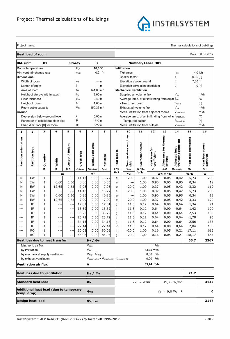
Bld. unit 01 Storey 3 Number/Label 301
Room temperature θi,H 16,0 °C
Min. vent. air change rate nmin 0,2 1/h
Dimensions
Width of room wf --- m
Length of room lf --- m
Area of room A f 141,00 m²
Height of storeys within axes ha 2,00 m
Floor thickness dflo 0,40 m
Height of room hf 1,60 m
Room cubic capacity VR 159,35 m³
Ground
Depression below ground level z 0,00 m
Perimeter of considered floor slab P ??? m
Char. dim. floor [X] for room B' ??? m
Infiltration
Tightness n50 4,0 1/h
Shelter factor e 0,05 [−]
Elevation above ground h 7,60 m
Elevation correction coefficient ε 1,0 [−]
Mechanical ventilation
Supplied air volume flux Vsu m³/h
Average temp. of air infiltrating from adjacent roomsθsu °C
- Temp. red. coef. fV,sup [−]
Exhaust air volume flux Vex m³/h
Mech. infiltration from adjacent rooms Vmech,inf,ij m³/h
Average temp. of air infiltrating from adjacent roomsθmech,inf, ij °C
- Temp. red. factor fV,mech,inf [−]
Mech. infiltration from outside Vmech,inf,e m³/h
Thermal calculations of buildingsProject name:
Heat load of room Date: 30.05.2017
Part
itio
n o
rien
tati
on
Part
itio
n t
yp
e
Qu
an
tity
Wid
th
Len
gth
/ H
eig
ht
Gro
ss a
rea
Win
d./
do
or
are
a
Net
are
a
Heat
loss t
o
Tem
pera
ture
on
oth
er
sid
e
Co
rrecti
on
facto
r
n b l/h AGross ADeduct ANet e/ug/j
θos
m m² °C
Heat
tran
sfe
rco
eff
icie
nt
ek/bu
fij/fg2
U
W/(m²·K)
All
ow
an
ce f
or
therm
al
bri
dg
es
ΔU
Ad
juste
d h
eat
tran
sfe
r co
eff
icie
nt
Uc/equiv
Heat
loss c
oeff
icie
nt
HT
W/K
Heat
loss a
cro
ss
part
itio
n
ΦT
W
1 2 3 4 5 6 7 8 9 10 11 12 13 14 15 16
N EW 1 --- --- 14,13 0,36 13,77 e -20,0 1,00 0,37 0,05 0,42 5,73 206
N EWi 1 0,60 0,60 0,36 0,00 0,36 e --- 1,00 0,90 0,05 0,95 0,34 12
N EW 1 12,65 0,63 7,96 0,00 7,96 e -20,0 1,00 0,37 0,05 0,42 3,32 119
N EW 1 --- --- 14,13 0,36 13,77 e -20,0 1,00 0,37 0,05 0,42 5,73 206
N EWi 1 0,60 0,60 0,36 0,00 0,36 e --- 1,00 0,90 0,05 0,95 0,34 12
N EW 1 12,65 0,63 7,99 0,00 7,99 e -20,0 1,00 0,37 0,05 0,42 3,33 120
--- IF 1 --- --- 17,81 0,00 17,81 j 11,8 0,12 0,64 0,00 0,64 1,34 71
--- IF 1 --- --- 18,89 0,00 18,89 j 11,8 0,12 0,64 0,00 0,64 1,42 100
--- IF 1 --- --- 33,72 0,00 33,72 j 11,8 0,12 0,64 0,00 0,64 2,53 135
--- IF 1 --- --- 23,72 0,00 23,72 j 11,8 0,12 0,64 0,00 0,64 1,78 95
--- IF 1 --- --- 34,15 0,00 34,15 j 11,8 0,12 0,64 0,00 0,64 2,56 136
--- IF 1 --- --- 27,14 0,00 27,14 ? 11,8 0,12 0,64 0,00 0,64 2,04 108
--- RO 1 --- --- 80,08 0,00 80,08 j -20,0 1,00 0,16 0,05 0,21 17,11 616
--- RO 1 --- --- 85,06 0,00 85,06 j -20,0 1,00 0,16 0,05 0,21 18,17 654
Heat loss due to heat transfer HT / ΦT 65,7 2367
Min. vent. air flux Vmin m³/h
Ventilation air flux V
Heat loss due to ventilation HV / ΦV
Standard heat load ΦHL
Design heat load ΦHL,Des
by infiltration V inf 63,74 m³/h
by mechanical supply ventilation Vsup · fV,sup 0,00 m³/h
by exhaust ventilation Vmech,inf,e + Vmech,inf,ij · fv,mech,inf,ij 0,00
m³/h63,74
21,7
3147
314719,75 W/m322,32 W/m2
m³/h
Additional heat load (due to temporarytemp. drop)
ΦRH 0fRH = 0,0 W/m²


Project: Thermal calculations of buildings
- 30 -InstalSystem 5 ALPHA-ROOT (Rev. 2.0.A22) © InstalSoft 1996-2017
Data and results for partitions
Partition definition name: ExW 0.45
Heat transfer coefficient: 0,37 W/(m²·K)
Description: External wall 0.45
Heat flow direction: Horizontal
Partition type: External wall
Heat capt. res. (int.): 0,130 (m²·K)/W
Heat capt. res. (ext.): 0,040 (m²·K)/W
No. Type d λ μ Cp ρ R
m W/(m·K) [−] J/(kg·K) kg/m³ (m²·K)/W
1 Tynk gipsowy 0,010 0,350 0,00 1000,0 1000,0 0,029
2 Styropian 0,090 0,043 0,00 1460,0 1000,0 2,093
3 Lekkie cegły 0,350 0,800 0,00 880,0 1000,0 0,438
Condensation occurs inside partition!
Internal temperature: 20 °C
Internal humidity: 60 %
External temperature: -10 °C
External humidity: 90 %
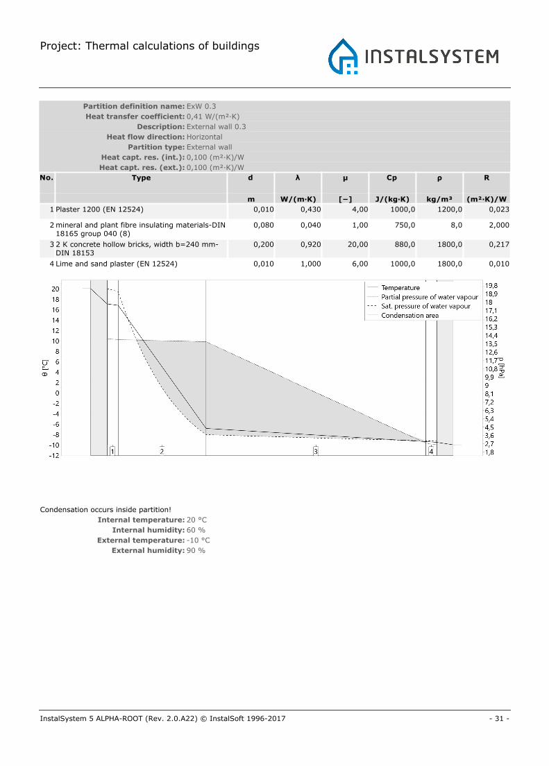
Project: Thermal calculations of buildings
- 31 -InstalSystem 5 ALPHA-ROOT (Rev. 2.0.A22) © InstalSoft 1996-2017
Partition definition name: ExW 0.3
Heat transfer coefficient: 0,41 W/(m²·K)
Description: External wall 0.3
Heat flow direction: Horizontal
Partition type: External wall
Heat capt. res. (int.): 0,100 (m²·K)/W
Heat capt. res. (ext.): 0,100 (m²·K)/W
No. Type d λ μ Cp ρ R
m W/(m·K) [−] J/(kg·K) kg/m³ (m²·K)/W
1 Plaster 1200 (EN 12524) 0,010 0,430 4,00 1000,0 1200,0 0,023
2 mineral and plant fibre insulating materials-DIN18165 group 040 (8)
0,080 0,040 1,00 750,0 8,0 2,000
3 2 K concrete hollow bricks, width b=240 mm-DIN 18153
0,200 0,920 20,00 880,0 1800,0 0,217
4 Lime and sand plaster (EN 12524) 0,010 1,000 6,00 1000,0 1800,0 0,010
Condensation occurs inside partition!
Internal temperature: 20 °C
Internal humidity: 60 %
External temperature: -10 °C
External humidity: 90 %
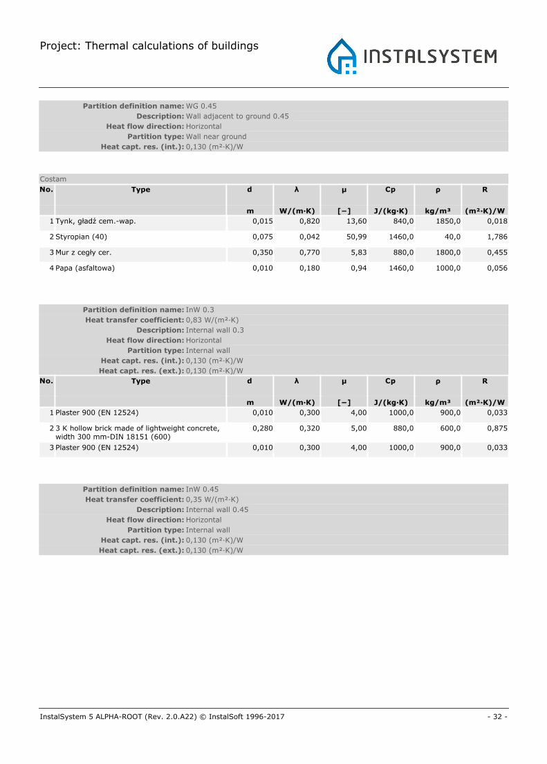
Project: Thermal calculations of buildings
- 32 -InstalSystem 5 ALPHA-ROOT (Rev. 2.0.A22) © InstalSoft 1996-2017
Partition definition name: WG 0.45
Description: Wall adjacent to ground 0.45
Heat flow direction: Horizontal
Partition type: Wall near ground
Heat capt. res. (int.): 0,130 (m²·K)/W
Costam
No. Type d λ μ Cp ρ R
m W/(m·K) [−] J/(kg·K) kg/m³ (m²·K)/W
1 Tynk, gładź cem.-wap. 0,015 0,820 13,60 840,0 1850,0 0,018
2 Styropian (40) 0,075 0,042 50,99 1460,0 40,0 1,786
3 Mur z cegły cer. 0,350 0,770 5,83 880,0 1800,0 0,455
4 Papa (asfaltowa) 0,010 0,180 0,94 1460,0 1000,0 0,056
Partition definition name: InW 0.3
Heat transfer coefficient: 0,83 W/(m²·K)
Description: Internal wall 0.3
Heat flow direction: Horizontal
Partition type: Internal wall
Heat capt. res. (int.): 0,130 (m²·K)/W
Heat capt. res. (ext.): 0,130 (m²·K)/W
No. Type d λ μ Cp ρ R
m W/(m·K) [−] J/(kg·K) kg/m³ (m²·K)/W
1 Plaster 900 (EN 12524) 0,010 0,300 4,00 1000,0 900,0 0,033
2 3 K hollow brick made of lightweight concrete,width 300 mm-DIN 18151 (600)
0,280 0,320 5,00 880,0 600,0 0,875
3 Plaster 900 (EN 12524) 0,010 0,300 4,00 1000,0 900,0 0,033
Partition definition name: InW 0.45
Heat transfer coefficient: 0,35 W/(m²·K)
Description: Internal wall 0.45
Heat flow direction: Horizontal
Partition type: Internal wall
Heat capt. res. (int.): 0,130 (m²·K)/W
Heat capt. res. (ext.): 0,130 (m²·K)/W
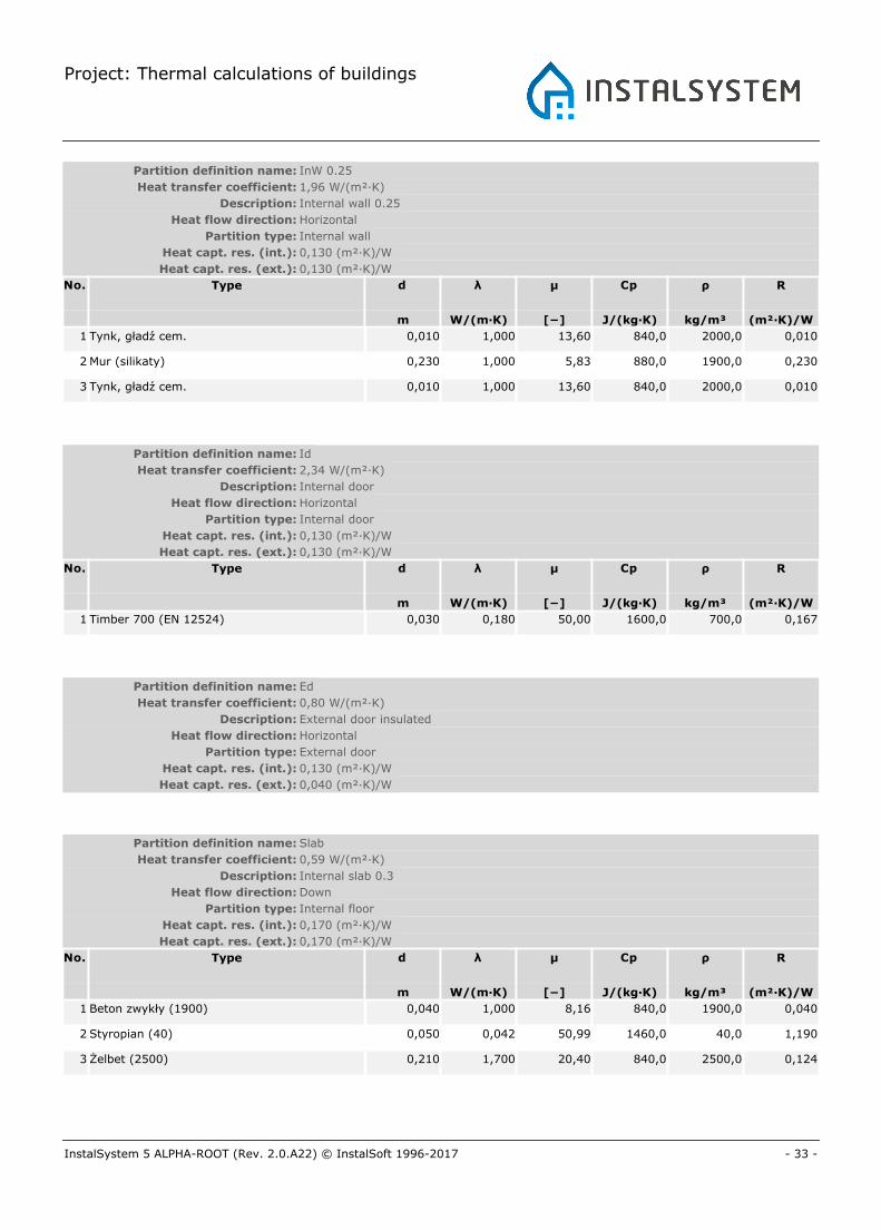
Project: Thermal calculations of buildings
- 33 -InstalSystem 5 ALPHA-ROOT (Rev. 2.0.A22) © InstalSoft 1996-2017
Partition definition name: InW 0.25
Heat transfer coefficient: 1,96 W/(m²·K)
Description: Internal wall 0.25
Heat flow direction: Horizontal
Partition type: Internal wall
Heat capt. res. (int.): 0,130 (m²·K)/W
Heat capt. res. (ext.): 0,130 (m²·K)/W
No. Type d λ μ Cp ρ R
m W/(m·K) [−] J/(kg·K) kg/m³ (m²·K)/W
1 Tynk, gładź cem. 0,010 1,000 13,60 840,0 2000,0 0,010
2 Mur (silikaty) 0,230 1,000 5,83 880,0 1900,0 0,230
3 Tynk, gładź cem. 0,010 1,000 13,60 840,0 2000,0 0,010
Partition definition name: Id
Heat transfer coefficient: 2,34 W/(m²·K)
Description: Internal door
Heat flow direction: Horizontal
Partition type: Internal door
Heat capt. res. (int.): 0,130 (m²·K)/W
Heat capt. res. (ext.): 0,130 (m²·K)/W
No. Type d λ μ Cp ρ R
m W/(m·K) [−] J/(kg·K) kg/m³ (m²·K)/W
1 Timber 700 (EN 12524) 0,030 0,180 50,00 1600,0 700,0 0,167
Partition definition name: Ed
Heat transfer coefficient: 0,80 W/(m²·K)
Description: External door insulated
Heat flow direction: Horizontal
Partition type: External door
Heat capt. res. (int.): 0,130 (m²·K)/W
Heat capt. res. (ext.): 0,040 (m²·K)/W
Partition definition name: Slab
Heat transfer coefficient: 0,59 W/(m²·K)
Description: Internal slab 0.3
Heat flow direction: Down
Partition type: Internal floor
Heat capt. res. (int.): 0,170 (m²·K)/W
Heat capt. res. (ext.): 0,170 (m²·K)/W
No. Type d λ μ Cp ρ R
m W/(m·K) [−] J/(kg·K) kg/m³ (m²·K)/W
1 Beton zwykły (1900) 0,040 1,000 8,16 840,0 1900,0 0,040
2 Styropian (40) 0,050 0,042 50,99 1460,0 40,0 1,190
3 Żelbet (2500) 0,210 1,700 20,40 840,0 2500,0 0,124
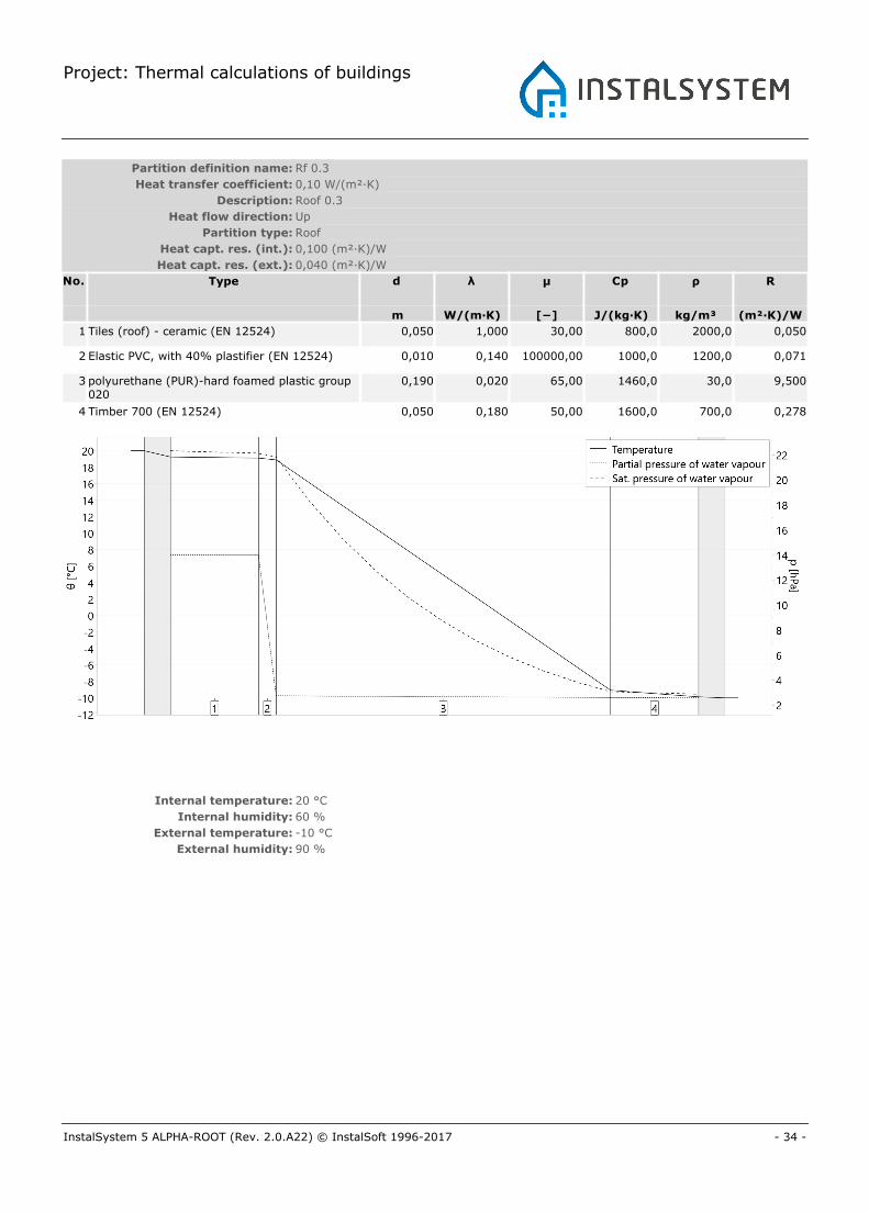
Project: Thermal calculations of buildings
- 34 -InstalSystem 5 ALPHA-ROOT (Rev. 2.0.A22) © InstalSoft 1996-2017
Partition definition name: Rf 0.3
Heat transfer coefficient: 0,10 W/(m²·K)
Description: Roof 0.3
Heat flow direction: Up
Partition type: Roof
Heat capt. res. (int.): 0,100 (m²·K)/W
Heat capt. res. (ext.): 0,040 (m²·K)/W
No. Type d λ μ Cp ρ R
m W/(m·K) [−] J/(kg·K) kg/m³ (m²·K)/W
1 Tiles (roof) - ceramic (EN 12524) 0,050 1,000 30,00 800,0 2000,0 0,050
2 Elastic PVC, with 40% plastifier (EN 12524) 0,010 0,140 100000,00 1000,0 1200,0 0,071
3 polyurethane (PUR)-hard foamed plastic group020
0,190 0,020 65,00 1460,0 30,0 9,500
4 Timber 700 (EN 12524) 0,050 0,180 50,00 1600,0 700,0 0,278
Internal temperature: 20 °C
Internal humidity: 60 %
External temperature: -10 °C
External humidity: 90 %
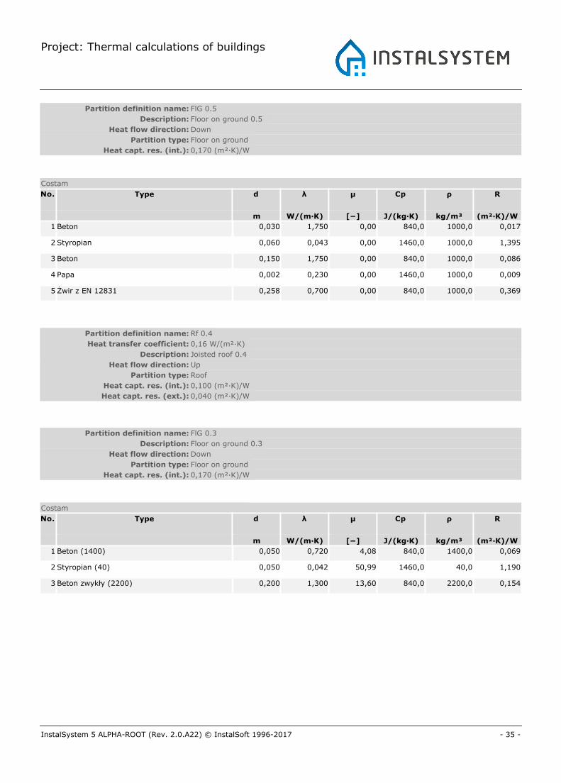
Project: Thermal calculations of buildings
- 35 -InstalSystem 5 ALPHA-ROOT (Rev. 2.0.A22) © InstalSoft 1996-2017
Partition definition name: FlG 0.5
Description: Floor on ground 0.5
Heat flow direction: Down
Partition type: Floor on ground
Heat capt. res. (int.): 0,170 (m²·K)/W
Costam
No. Type d λ μ Cp ρ R
m W/(m·K) [−] J/(kg·K) kg/m³ (m²·K)/W
1 Beton 0,030 1,750 0,00 840,0 1000,0 0,017
2 Styropian 0,060 0,043 0,00 1460,0 1000,0 1,395
3 Beton 0,150 1,750 0,00 840,0 1000,0 0,086
4 Papa 0,002 0,230 0,00 1460,0 1000,0 0,009
5 Żwir z EN 12831 0,258 0,700 0,00 840,0 1000,0 0,369
Partition definition name: Rf 0.4
Heat transfer coefficient: 0,16 W/(m²·K)
Description: Joisted roof 0.4
Heat flow direction: Up
Partition type: Roof
Heat capt. res. (int.): 0,100 (m²·K)/W
Heat capt. res. (ext.): 0,040 (m²·K)/W
Partition definition name: FlG 0.3
Description: Floor on ground 0.3
Heat flow direction: Down
Partition type: Floor on ground
Heat capt. res. (int.): 0,170 (m²·K)/W
Costam
No. Type d λ μ Cp ρ R
m W/(m·K) [−] J/(kg·K) kg/m³ (m²·K)/W
1 Beton (1400) 0,050 0,720 4,08 840,0 1400,0 0,069
2 Styropian (40) 0,050 0,042 50,99 1460,0 40,0 1,190
3 Beton zwykły (2200) 0,200 1,300 13,60 840,0 2200,0 0,154
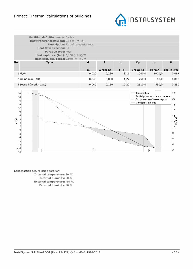
Project: Thermal calculations of buildings
- 36 -InstalSystem 5 ALPHA-ROOT (Rev. 2.0.A22) © InstalSoft 1996-2017
Partition definition name: Dach a
Heat transfer coefficient: 0,14 W/(m²·K)
Description: Part of composite roof
Heat flow direction: Up
Partition type: Roof
Heat capt. res. (int.): 0,100 (m²·K)/W
Heat capt. res. (ext.): 0,040 (m²·K)/W
No. Type d λ μ Cp ρ R
m W/(m·K) [−] J/(kg·K) kg/m³ (m²·K)/W
1 Płyty 0,020 0,230 8,16 1000,0 1000,0 0,087
2 Wełna min. (40) 0,340 0,050 1,27 750,0 40,0 6,800
3 Sosna i świerk (p.w.) 0,040 0,160 10,20 2510,0 550,0 0,250
Condensation occurs inside partition!
Internal temperature: 20 °C
Internal humidity: 60 %
External temperature: -10 °C
External humidity: 90 %
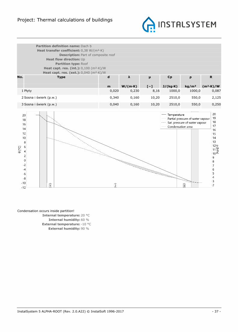
Project: Thermal calculations of buildings
- 37 -InstalSystem 5 ALPHA-ROOT (Rev. 2.0.A22) © InstalSoft 1996-2017
Partition definition name: Dach b
Heat transfer coefficient: 0,38 W/(m²·K)
Description: Part of composite roof
Heat flow direction: Up
Partition type: Roof
Heat capt. res. (int.): 0,100 (m²·K)/W
Heat capt. res. (ext.): 0,040 (m²·K)/W
No. Type d λ μ Cp ρ R
m W/(m·K) [−] J/(kg·K) kg/m³ (m²·K)/W
1 Płyty 0,020 0,230 8,16 1000,0 1000,0 0,087
2 Sosna i świerk (p.w.) 0,340 0,160 10,20 2510,0 550,0 2,125
3 Sosna i świerk (p.w.) 0,040 0,160 10,20 2510,0 550,0 0,250
Condensation occurs inside partition!
Internal temperature: 20 °C
Internal humidity: 60 %
External temperature: -10 °C
External humidity: 90 %
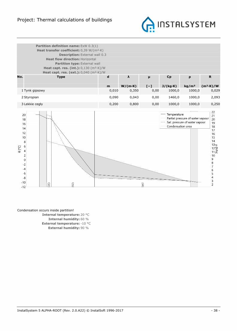
Project: Thermal calculations of buildings
- 38 -InstalSystem 5 ALPHA-ROOT (Rev. 2.0.A22) © InstalSoft 1996-2017
Partition definition name: ExW 0.3(1)
Heat transfer coefficient: 0,39 W/(m²·K)
Description: External wall 0.3
Heat flow direction: Horizontal
Partition type: External wall
Heat capt. res. (int.): 0,130 (m²·K)/W
Heat capt. res. (ext.): 0,040 (m²·K)/W
No. Type d λ μ Cp ρ R
m W/(m·K) [−] J/(kg·K) kg/m³ (m²·K)/W
1 Tynk gipsowy 0,010 0,350 0,00 1000,0 1000,0 0,029
2 Styropian 0,090 0,043 0,00 1460,0 1000,0 2,093
3 Lekkie cegły 0,200 0,800 0,00 1000,0 1000,0 0,250
Condensation occurs inside partition!
Internal temperature: 20 °C
Internal humidity: 60 %
External temperature: -10 °C
External humidity: 90 %


![THE NEGOTIABLE INSTRUMENTS ACT - Gujgujcourts.guj.nic.in/acts/THE_NEGOTIABLE_INSTRUMENTS_ACT.pdf · THE NEGOTIABLE INSTRUMENTS ACT, 1881 ACT NO. 26 OF 1881 [9th December, 1881.] An](https://img.pdfslide.us/doc/110x75/5a78cef57f8b9a83238cc17f/the-negotiable-instruments-act-negotiable-instruments-act-1881-act-no-26-of.jpg)