Embed Size (px)
Citation preview

Installing the Gear Vendors Overdrivein the Silver Ghost
A compilation of advice from Dave Browne, Bob Jefferson, Bill Kennedy, Steve Litman, DavidMorrison, Jim Stroman, Bob Thompson, Doug White and Rick Johnson of Gear Vendors, Inc.
Text and photos by Gil Fuqua, Tennessee
The Gear Vendors overdrive comes pre-fitted with cast aluminum adapters that replace the front section of the SilverGhost's torque tube. The adapters are made to the exact length of the removable section of your Ghost's torque tube.
Gear Vendors' makes an electrically activated overdrivefor the Silver Ghost that provides a 22% re-duction in engine RPMs when engaged at a given
speed (Table 1). The overdrive is based on a proven designcreated by Laycock Manufacturing and incorporates planetarygears that have been used for over a half century in drive trainsby GM, Ford, John Deere and Detroit Allison. The Gear Ven-dors overdrive is rated to handle 30,000 pounds gross com-bined vehicle weight, more than enough reserve to handle thelargest Ghost.
The advantages of the overdrive include lower engine anddrive train noise, ability to achieve higher cruising speeds,and reduced RPMs at existing cruising speeds. Reduced RPMsmean less wear on your engine and transmission, lower stresseson crankshafts and bearings from high rotational speeds (stressvaries as the square of the speed)2 and may improve gas mile-age. Since the higher gearing allows you to drive faster, it'simportant to remember you still have to stop your Ghost, andit takes longer to stop at higher speeds. Think ahead anddrive accordingly!
The Gear Vendors overdrive provides about the same topgear performance for a standard 14/52 rear axle as an 18/52ring and pinion. The costs of the overdrive and new gears aresimilar; however, the overdrive is easier and faster to installand does not require the services of an expert gear fitter. An
advantage of the overdrive coupled with the 14/52 rear axle isthe combination of low end pulling power of the original gearscombined with the high speed cruising allowed by the over-drive.
The Gear Vendors over-drive comes pre-assembledwith fittings that bolt directlyto the Ghost's torque tube.No structural modificationsare required to the Ghost'schassis or driveline and theoverdrive installation can beeasily reversed. The instal-lation requires the torquetube to be unbolted from thesphere, and the axle backedout so that the front sectionof the torque tube can be re-moved and replaced with theoverdrive unit (Photo nextpage). Once installed, anumber of wires and switchesare connected to the over-drive and control box to pro-vide a means of control.
The overdrive is shown nextto the torque tube section itreplaces.
941

Table 1Silver Ghost Rear Axle Gear Ratio
Comparisons*
Adapted from data compiled by David Morrison
Four Speed Transmission
Rear Axle Ratio'
3.71 (14/52)3.71
(14/52 w/OD2)
3.47 (15/52)3.25 (16/52)3.06 (17/52)2.89 (18/52)2.74 (19/52)
Ist Gear
3.403.40
3.172.982.802.642.51
2nd Gear
2.222.22
1.73 od
2.071.941.831.731.64
3rd Gear
1.491.49
1.16 od
1.391.301.231.161.10
4th Gear
1.001.00
0.930.880.820.780.74
Overdrive
0.78 od
0.73 od0.68 od0.64 od0.61 od0.57 od
Three Speed Transmission
Rear Axle Ratio1
3.71 (14/52)3.71
(14/52 w/OD2)
3.47 (15/52)3.25 (16/52)3.06 (17/52)2.89 (18/52)2.74 (19/52)
1st Gear2.862.86
2.672.502.362.222.11
2nd Gear1.511.51
1.18 od
1.411.321.241.171.11
3rd Gear1.001.00
0.930.880.820.780.74
Overdrive
0.78 od
0.73 od0.68 od0.64 od0.61 od0.57 od
*Tables assume a 14/52 gear ratio is the standard drive ratio; resulting in direct 1:1 drive in top gear. All data is used tocompare relative differences in gear ratios to a standard 14/52 rear axle. For example, the 4th gear of the 14/52 rear endprovides direct drive at 1.00, or one engine revolution per revolution of the drive shaft. With the overdrive engaged, theengine rotates at .78 times the drive shaft RPMs. Note that a 14/52 rear axle with a 22% overdrive provides a finaldrive of. 78, or about the same gearing as an 18/52 without an overdrive.
1Ring and pinion gears shown in parenthesis.2A 3.71 rear axle "w/ OD" is listed to show the potential for 'gear-splitting.' In effect, you can engage the overdrive tocreate half steps between gears to more optimally match engine RPMs with the terrain.
The overdrive replaces the front section of thetorque tube on a bolt-for-bolt basis
The Gear Vendors overdrive for the Silver Ghost is avail-able from Sports Classics Ltd3 (Bob Jefferson), Jim Stroman4
and Gear Vendors, Inc.
The Mathematics of an Overdrive, or How a22% Overdrive Boosts Top Speed by 28%
A conventional gearbox provides a straight-through out-put in top gear with a one-to-one relationship between en-gine revolutions and the output shaft of the transmission.An overdrive provides a mechanical advantage with an out-put that is greater than one-to-one. The Gear Vendors over-drive has an output of one revolution for each .778 inputrevolution from the transmission and is normally referredto as a 22% overdrive (1.000 - 0.778 = .222 or 22.2%).
942

Simple logic would indicate that a 22% overdrive allowsyou to go 22% faster at the same engine speed - Not True!Road speed is the reciprocal of the overdrive's output (1.000divided by .778 = 1.285). The Gear Vendors 22% overdriveextends your cruising speed by 28% at the same RPMs com-pared with top gear without overdrive. For example, if yourGhost's optimum cruising speed in top gear is 60 mph, it willincrease to approximately 77 mph with the Gear Vendors over-drive (60 mph x 1.285 = 77.1 mph) based on the same engineRPMs of 2,136.
Tire revolution, which is proportional to ground speed, isaffected by three factors: (1) the revolutions of the drive shaft,(2) the rear axle ratio, and (3) the diameter of the tires. Forexample, a Silver Ghost with 35" diameter tires (a 33 x 5 tirestandard on a late Ghost has a 35" tire diameter) travels 9.161'per tire revolution (35" (tire diameter) divided by 12" = 2.917'x pi (3.141) = 9.161'). In one mile, the Ghost's tires revolve576.4 times (5,280' (feet in a mile) divided by 9.161' = 576.4
Table 2Engine Revolutions Per Tire Turn*
(Assumes 35" diameter tires)Four-Speed Transmission
Rear AxleRatio1
3.71 (14/52)
3.47 (15/52)3.25 (16/52)3.06 (17/52)2.89 (18/52)2.74 (19/52)
1st Gear
12.61
11.8011.0510.409.839.32
2nd Gear
8.24
7.707.226.796.426.08
2"dOD
6.42
6.005.625.295.004.74
3rd Gear
5.53
5.174.844.564.314.08
3rdOD
4.30
4.033.773.553.353.18
4th Gear
3.71
3.473.253.062.892.74
RPMs2
at60
mph2,136
1,9981,8711,7621,6641,577
4thOD
2.89
2.702.532.382.252.13
RPMs2
at60
mph1,662
1,5541,4561,3711,2951,227
Three-Speed Transmission
Rear Axle Ratio1
3.71 (14/52)3.47 (15/52)3.25 (16/52)3.06 (17/52)2.89 (18/52)2.74 (19/52)
1st Gear
10.619.929.308.758.277.75
2nd Gear
5.605.244.914.624.364.14
2nd OD
4.384.093.843.613.413.23
3rd Gear
3.713.473.253.062.892.74
RPMs2
at60 mph
2.1361 9981,8711,7621,6641,577
3rdOD
2.892.702.532.382.252.13
RPMs2
at60mph
1.6621.5541,4561,3711,2951,227
*Table 2 shows the number of engine revolutions for each revolution of the rear tires. For example, with a four-speedtransmission in first gear (3.71 rear axle ratio), the engine revolves 12.61 times for each revolution of the rear tires. Thefourth gear output (high gear) is directly proportional to engine RPMs times the rear axle ratio, or 3.71 in this example.With the Gear Vendors overdrive engaged, engine revolutions drop to 2.89 per rear tire revolution, or approximately22% less than top gear without overdrive.
1Ring and pinion gears shown in parenthesis.2Approximate RPMs at 60 mph are shown for each rear axle ratio in top gear with and without overdrive.
tire revolutions per mile) and it is also equal to the number oftire revolutions per minute at 60 mph.
A Ghost with a 14/52 ring and pinion has a rear axle ratioof 3.71 (52 tooth ring gear divided by 14 tooth pinion gear =3.71). Traveling at 60 mph, engine RPMs are approximately2,136 and can be calculated by multiplying the rear axle ratioof 3.71 times 576.4 revolutions per minute of the rear tires.With the Gear Vendors overdrive engaged, engine RPMs willbe approximately 1,662 at 60 mph (.778 x 2,136 (RPMs at 60mph without overdrive) = 1,662), or 22% less. Alternatively,RPMs in overdrive at 60 mph can be calculated by multiply-ing the effective rear end ratio in overdrive (2.89 for a 14/52ring and pinion) times 576.4 RPMs of rear tires = 1,662. Ineffect, engine RPMs at 60 mph in overdrive are the same asengine RPMs at 46.7 mph in normal high gear (.778 x 60 =46.7) without overdrive. See Table 2 for comparison of en-gine revolutions per tire rotation.
943

Disconnecting the Torque Tube from the Sphere
Prior to unbolting the torque tube from the sphere, discon-nect all of the items between the rear axle and chassis, includ-ing the brake cables, shocks and springs. You need about 10'behind the chassis to roll out the rear axle and torque tubeonce disconnected.1. Jack up the rear of the chassis. Use a jack with rollers so that
you can support the rear axle when you roll out the axle andtorque tube from under the chassis. The chassis should beraised high enough so that the rear axle can pass under thepetrol tank. (Measure the height of the jack at its lowest pointcombined with the height of the rear axle to determine clear-ance required under the petrol tank. Also check for clear-ance of brake drums under rear fenders.) Chock the frontwheels and place heavy-duty jack stands under the chassisrails near the center point of the springs. (You will needjack stands that extend at least 24".) Also place a secondset of stands under the chassis near the transmission as asafety measure. Lower the chassis on to the jack stands.
2. Remove the rear wheels.3. Disconnect the rear brake cables.4. Disconnect the rear springs by removing the safety bolt at
the rear end of each spring.5. Disconnect the rear shock absorbers. Be sure the axle is
supported by the jack.6. Disconnect the torque tube. David Morrison suggests re-
moving the floorboards to provide better access to the areawhere the torque tube bolts to the sphere. He also suggestsusing a board set across the window sills with a block andtackle attached to the board to support the weight of thetorque tube and lower it once removed.Remove the ring of 12 - 5/16" BSF nuts and washers that
connect the torque tube to the sphere. Clean up the nutswith a tap. This allows the nuts to be installed finger tightwhen refitting and makes the job easier. You will need tosupport the front of the torque tube once it is removed.Consider tying a safety rope across the chassis rails to catchthe torque tube in the event it falls.
7. Be sure the rear axle is disconnected from the brake cables,shock absorbers and springs before proceeding.
8. Lower the rear axle till the springs just clear the carrier onthe axle at the rear of the springs and pull back the axle/torque tube to clear the spring assembly. Lower the rearaxle. Roll the axle/torque tube from under the chassis us-ing the brake drums or jack as wheels. CAUTION: Sup-port the front end of the torque tube to keep oil from run-ning out. A rolling seat (lower left photo) provides an idealsupport to hold the front of the torque tube in an elevatedposition and aids the removal and reinstallation process.
With the axle/torque tube removed, you now have easyaccess to the rear of the chassis. Take the opportunity tocheck shocks, exhaust lagging, wiring at rear of chassis,sphere, petrol tank, etc. Dave Morrison suggests this is aperfect opportunity to clean and rebuild the rear springssince you have to pull out the axle to disconnect the springsat the rear from the axle. He also noted that he had toremove the rear fenders and running boards on his RRCCWbody in order to remove the springs from the chassis.
1. Remove the front section of the torque tube. The front sec-tion of the torque tube has a ring of 20 - 5/16" BSF nutsand bolts (photo below) that connects it to the rear sectionof the torque tube.
Removing the Front Section of the Torque Tube
The axle and torque tube are backed out from under thechassis on the brake drums and supported by a rollingjack under the differential. Also support the front of thetorque tube to keep oil from running out of the differential.You need about 10' behind the chassis to accommodatethe roll back of the axle and torque tube assembly.
The front section of the torque tube is connected to therear section by a ring of 20 - 5/16" BSF nuts. Loosen thenuts with an open face wrench and then use a 5/16" BSFsocket turned down to fit the tight clearance and speedremoval.
944

After removing the front section of the torque tube, theinner drive shaft is exposed. A serrated nut with aninternal locking ring secures the inner drive shaft to thesplined coupling.
The rear of the overdrive has a 12 splined cog and issimilar to the end of the original inner drive shaft.Note: Gear Vendors makes a cog for the early andlate series Ghost that are different lengths.
Jim Stroman suggests turning down a 5/16" BSF socket tofit the tight clearance between the nuts and torque tube. Aratchet wrench will greatly speed the removal of the 20nuts that have to be removed. Clean up the threads of thenuts and bolts to ease reinstallation.
2. Slide the outer tube off to expose the inner drive shaft (up-per left photo).
3. The inner drive shaft is secured to the rear half by a ser-rated nut with an internal locking wire ring. Remove thelocking wire ring from inside the serrated nut.
4. Remove the serrated nut (right-handed).5. Withdraw the inner drive shaft from the splined coupling.
Checking Universal Joint and Bearings
Check the universal joint in the sphere for wear. If thewear in the sphere indicates a rebuild is in order, this is agood opportunity to tackle the job since the torque tube is al-ready removed (and also doubles the time required to get thecar back together.)
Check the bearing behind the spline in the torque tube. Ifthe bearing is suspect, this is a good opportunity to replace it.Bob Jefferson recommends replacing it with a sealed bearing.
Installing Overdrive in Drive Line
1. Trial fit the overdrive unit to the torque tube by mating thesplines in the overdrive with the torque tube (upper rightphoto). It should fit flush on the torque tube without ex-cess pressure. Gear Vendors provides two different cou-plings to fit early and late Ghosts. The early Ghost cou-pling is deeper and will not mate properly to a later Ghost'storque tube. Bob Thompson suggests you trial fit the over-drive to the torque tube with a piece of plastigage on theend of the splined shaft to be sure there is end clearancebetween the overdrive unit and the torque tube.
A splined shaft comes with the Gear Vendor'soverdrive. The small splines fit into the front of theoverdrive. The large splines mate with the sphere.Note the circlip that prevents the splined shaft fromshifting forward into the sphere and slipping out of theoverdrive unit splines.
2. Bolt the overdrive unit to the torque tube (photo pg 941).You may find it easier to substitute short 5/16" BSF nuts inplace of the long, original Rolls-Royce nuts in a few posi-tions due to interference with the overdrive case.
3. Trial fit the coarse splined end of the shaft (photo above)provided with the overdrive to the sphere. Be sure the splinesmate easily with a slip fit. The shaft should seat deep enoughinto the sphere so that the splines are completely inside thesphere. If the splines are visible outside the sphere, checkthe following:
A. The shaft supplied by Gear Vendors may bind inthe sphere and require light filing for a slip fit. The author'sshaft could only be inserted about V2" and would bind. Lay-out blue was sprayed on the coarse splines and refitted. Thelayout blue indicated the grooves between the splines werebinding in the sphere. Light filing in each of the grooveseliminated the problem.
B. On late English Ghosts, there is a bell-mouthedshaped oil baffle sweated into the rear sphere housing thatwas designed to retain oil in the sphere (photo pg 946).With the baffle fitted, the opening is too small to allow theoverdrive shaft with the circlip attached (photo pg 946) to
945

The rear half of the sphere is pictured from its insideface and shows the bell-mouthed shaped oil bafflesoldered in place. It is designed to keep oil in thesphere and from draining down the torque tube. It wasfitted to the sphere of the late British Silver Ghosts andto the PI.
The back of the sphere is shown with the circlip of theoverdrive shaft against the external face of the bell-mouthed oil baffle that is soldered in place. The oilbaffle must be removed in order for the overdriveshaft with the circlip to fully seat in the sphere.
be fully inserted into the sphere. Jim Stroman encounteredthis problem on Jim Armstrong's Ghost, 74AU, and alsofound the remedy. The oil baffle is sweated in and can beaccessed by removing the back half of the sphere. Applyheat to the edges of the oil baffle to melt the solder, andlightly tap the oil baffle out from inside the sphere. Theauthor encountered this obstacle on 3AU.
To remove the back half of the sphere, remove thefour 5/16" BSF nuts at the top and bottom of the sphere.Remove the 12 - 3/16" BSF nuts on each side of the sphereand the underlying washers. You should be able to with-draw the back half of the sphere to gain access to the oilbaffle at the workbench. New leather washers designed toseal the floating edge of the sphere should be refitted and
are available from Coldwell Engineering.5 The leatherwasher seals (RR part # G6584) are designed to keep oil inthe sphere and water out.
4. Push or pull the axle and torque tube back under the chas-sis while lining up the rear spring connections. BillKennedy used a rope to pull the axle and torque tube backunder the chassis. If you roll the axle and torque tube as-sembly back under the chassis on the brake drums, notethat the splined shaft in the overdrive rotates as the brakedrums turn, making the final alignment with the fixedsphere difficult. Use the rolling jack to lift the brake drumsoff the ground and roll the axle and torque tube the last fewinches on the jack to mate with the sphere. An assistantcan turn a rear brake drum to precisely line up the splinedshaft from the overdrive to mate with the sphere.
The splined shaft (seen in photo on pg 945) fits into thefront of the overdrive and attaches directly to thesphere in place of the front section of the torque tube.
The front shaft of the overdrive should have a circlip(above photo) positioned near the shaft's end with coarsesplines. Be sure the circlip is in place since it prevents thesplined shaft from shifting forward into the sphere and slip-ping out of the overdrive unit splines. Bolt the front of theoverdrive unit to the sphere with the splined shaft installedin the overdrive unit. The overdrive unit is heavier thanthe front section of the torque tube that was removed. Youmay need assistance in holding the unit up while it is re-connected to the sphere. David Morrison suggests using ablock and tackle or 'come-along' to lift the torque tube andsupport it while refitting to the sphere.
5. Check the clearance between the overdrive and the brakeequalizer bar. On some chassis, the breather plug on top ofthe overdrive is directly beneath the brake equalizer bar.Some installations have had the breather plug smash againstthe brake equalizer bar when the springs bottom out.
If your brake equalizer bar is directly above thebreather, Gear Vendors suggests you remove the rear leafsprings and jack up the differential against the axle stopsto check the clearance between the breather and brake equal-izer bar. WARNING: Contact between the overdrive andbrake equalizer bar while driving could cause damage tothe overdrive and affect the structural integrity of the driv-eline. Gear Vendors recommends that taller axle stops beinstalled or the existing axle stops shimmed to limit the
946
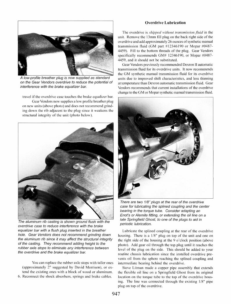
A low-profile breather plug is now supplied as standardon the Gear Vendors overdrive to reduce the potential ofinterference with the brake equalizer bar.
travel if the overdrive case touches the brake equalizer bar.Gear Vendors now supplies a low profile breather plug
on new units (above photo) and does not recommend grind-ing down the rib adjacent to the plug since it weakens thestructural integrity of the unit (photo below).
The aluminum rib casting is shown ground flush with theoverdrive case to reduce interference with the brakeequalizer bar with a flush plug inserted in the breatherhole. Gear Vendors does not recommend grinding downthe aluminum rib since it may affect the structural integrityof the casting. They recommend adding height to therubber axle stops to eliminate any interference betweenthe overdrive and the brake equalizer bar.
You can replace the rubber axle stops with taller ones(approximately 2" suggested by David Morrison), or ex-tend the existing ones with a block of wood or aluminum.
6. Reconnect the shock absorbers, springs and brake cables.
Overdrive Lubrication
The overdrive is shipped without transmission fluid in theunit. Remove the 13mm fill plug on the back right side of theoverdrive and add approximately 26 ounces of synthetic manualtransmission fluid (GM part #12346190 or Mopar #0487-4459). Fill to the bottom threads of the plug. Gear Vendorsspecifically recommends GM# 12346190, or Mopar #0487-4459, and it should not be substituted.
Gear Vendors previously recommended Dexron 11 automatictransmission fluid for its overdrive units. It now recommendsthe GM synthetic manual transmission fluid for its overdriveunits due to improved shift characteristics, and less thinningat temperature than Dexron automatic transmission fluid. GearVendors recommends that current installations of the overdrivechange to the GM or Mopar synthetic manual transmission fluid.
There are two 1/8" plugs at the rear of the overdrivecase for lubricating the splined coupling and the centerbearing in the torque tube. Consider adapting anEnot's orAlemite fitting, or extending the oil line on alate Springfield Ghost, to one of the plugs to aid inperiodic lubrication.
Lubricate the splined coupling at the rear of the overdrivehousing. There is a 1/8" plug on top of the unit and one onthe right side of the housing at the 9 o'clock position (abovephoto). Add gear oil through the top plug until it reaches thelevel of the plug on the side. This should be added to yourroutine chassis lubrication since the installed overdrive pre-vents oil from the sphere reaching the splined coupling andintermediate bearing behind the overdrive.
Steve Litman made a copper pipe assembly that extendsthe flexible oil line on a Springfield Ghost from its originallocation on the torque tube to the top of the overdrive hous-ing. The line was connected through the existing 1/8" pipeplug on top of the overdrive.
947

Connecting Speedometer and Electric Controls
Gear Vendors control unit serves as a junction box forall the wiring. The unit senses the speed of the car andprevents the overdrive from being engaged in reverse orat slow speeds that would damage the overdrive.
The overdrive is shipped with an analog electronic controlunit (above photo) that serves as a junction box for all wiring.The control unit also prevents the overdrive from being en-gaged at speeds slower than 20 mph and prevents the over-drive from being operated in reverse. The electronic controlincludes provisions for additional external lockouts to behooked into the system. The Gear Vendors overdrive can beinstalled without the control box and there are strong advo-cates for the simplified installation.
Some installations experienced problems with the digitalcontrol units that were supplied by Gear Vendors in the past,such as dropping out of overdrive. This problem may be re-lated to RF (radio frequency) interference generated by theGhost's unshielded ignition system or the digital unit's volt-age sensitivity. The magneto is particularly suspect since itgenerates an inordinate amount of RF. If the digital controlbox is used, it should be placed as far away from the ignitioncomponents as possible to minimize the problem.
Gear Vendors recommends that their analog control boxbe used on the Silver Ghost due to the reduced potential forRF interference and the fact that the analog unit is less sus-ceptible to voltage variances than the digital unit. A Ghostmay experience a drop in voltage when the car is started orwhen lights are turned on, potentially damaging the voltagesensitive digital control box. Gear Vendors will substitute ananalog control box for the digital controller.
The overdrive can be connected and energized without thecontrol box; however, Gear Vendors requires dealer installedunits to have the control box installed in order to retain themanufacturer's warranty. Bill Kennedy and Steve Litman in-stalled an overdrive solely with a switch wired to provide powerto the solenoid, thereby engaging the overdrive. This instal-lation eliminates the potential problems of the electronic con-trol unit and simplifies the installation. Without the electroniccontrol box, it' s important to install some form of lockout wherethe overdrive cannot be engaged in lower gears or in reverse.The overdrive is not designed to work in reverse; and at speeds
slower than 20 mph. At slow speeds, the overdrive's internalhydraulic pump does not create enough pressure to hold theoverdrive clutch tight and will result in the clutch slipping. Ifyou are the least bit forgetful, you should install the controlbox to eliminate any chance of leaving the overdrive engagedin slow speeds or in reverse.
Hooking up the Electronic Control Box
Wiring to the control box is straight forward and is sim-plified by color coded connectors that use telephone style RJ-11 jacks to plug into the control unit. Be sure cables avoidsharp edges and possible contact with areas of excessive heat.
All the wiring connectionsare made with telephonestyle, RJ-11, jacks that arecolor-coded and plug intothe Gear Vendor's controlbox. These connectors arenot waterproof and thecontrol box should not beexposed to potential watercontamination
Wiring the overdrive and electronic control box:
A. Mount the electronic control box in a location that will notbe exposed to the weather and has good air circulation.
B. Hook up the wires to the solenoid (no polarity) and controlbox (white color coded connector.)
The signal generator sensoris connected to the front ofthe speedometer cableextension that is suppliedwith the overdrive. Thesensor provides the controlbox with a signal thatindicates speed and is usedto mate the Ghost'sspeedometer cable to theextension speedometer cableconnected to the overdrive.
C. Hook up the wires to the signal generator sensor (abovephoto) and control box (yellow color coded connector.)The signal generator wires have no polarity.
The master switch is used to provide power to the controlbox. A green light on the switch provides visual indicationthat the overdrive can be activated.
948

D. Hook up the master on/off switch (red color coded connec-tor - photo lower right, pg 948). The master switch in-cludes a green light that illuminates when the overdrivecan be activated. It can be mounted under the dash.
A manual switch is used to engage the overdrive unit. ASPST switch can be substituted for the one supplied byGear Vendors to turn on the overdrive, including a footswitch or smaller switch that is more concealable.
E. Hook up the manual overdrive switch (large red knob witha black color coded connector - above photo). The manualoverdrive switch can be mounted under the dash or on thegear shift lever. Alternatively, you can install a foot switchor other less conspicuous switch to turn on the overdrive.A simple single pole single throw (SPST) switch can besubstituted to fit your installation requirements. SteveLitman substituted a switch with a push-pull mechanismthat had a knob that illuminates when the overdrive is ac-tivated. The author used a toggle switch with a handle thatlights when the overdrive is activated.
F. Connect electronic control box to a source of switched 12volts (red color coded RCA plug) using the in-line 5 ampfuse provided. (NOTE: add a box of 5 amp AGC fuses toyour spares kit.) For 6-volt cars, an inverter can be used toboost the voltage to 12 volts for the control box.
G. Connect ground wire (black color coded RCA plug) to agood ground point on chassis.Install lockout switches as desired. Some installations have
placed micro-switches in the first, second and reverse geargates to assure that the overdrive cannot be engaged in thesepositions. According to Gear Vendors, the lockouts are un-necessary with the control box since the signal generator sen-sor detects the vehicle's speed. The combination of the signalgenerator and control box are designed to prevent the over-drive from being engaged in reverse and at speeds slower than20 mph.
Hooking up Speedometer and Calibrating Output
The overdrive unit is supplied with an extension speedom-eter drive cable. Disconnect the speedometer cable from theGhost's transmission and attach it to the extension cable us-ing the signal generator sensor (photo pg 948) to mate the twocables. You may have to fabricate an adapter to mate theGhost's speedometer cable to the overdrive cable. This is agood opportunity to check and lubricate the speedometer cable.
A ratio specific replaceable plastic gear is locatedbehind the speedometer drive in the overdrive and canbe changed to match the Ghost's tire size and rear axleratio for accurate speedometer readings. See Table 3.
The speedometer should read correctly at all speeds, both inoverdrive and without overdrive, since it is connected directlyto the output shaft of the overdrive. The plate behind the speed-ometer coupling on the overdrive houses the speedometer drivegears and can be changed to match tire size and rear axle ratio(above photo). Gear Vendors uses standard plastic speedom-eter gears designed for a GM turbo 400 transmission (Table 3,pg 956). Note: Gear Vendors overdrives sold prior to Decem-ber 2000 have a different internal drive gear and Table 3 isnot applicable. Contact the author for information regardingspeedometer gears for units sold prior to December 2000.
The Overdrive in Operation
Take your Ghost for a test drive after double checking wir-ing and lubrication. Before activating the overdrive, drive yourcar for a few miles to check for any vibration in the drivelineand to insure initial component lubrication in the overdrive.
If you installed the control box, turn on the master powerswitch (bottom photo, pg 948). With your Ghost traveling atleast 20 miles per hour, the green light on the master switchshould illuminate providing visual indication that the over-drive can be activated. (Never reverse the car if the greenlight is illuminated, to avoid damaging the overdrive.)
Engage the overdrive by depressing the clutch and activat-ing the overdrive's solenoid through the manual switch (leftphoto above). In addition to extending your top end cruisingspeed, the overdrive can be used as a "split-gear system," pro-viding a half-step between existing gears. For example, youmay have encountered terrain where engine RPMs were toolow in fourth gear and too high in third gear. The overdrive
continued on page 956
949

continued from pg 949Table 3
Overdrive Speedometer Gears for the Silver Ghost
compiled by Gil Fuqua
Rear axleGears14/5215/5216/5217/5218/5219/52
GearRatio3.71:13.47:13.25:13.06:12.89:12.74:1
Approx RPMsat 60 MPH'
2,1361,9981,8711,7621,6641,577
Tire Diameter2
35"35"35"35"35"35"
Multiplier Gears'
——1.111.251.251.25
# Teeth4
363435373534
Gear Color
WhiteLt. Green
PinkRedPink
Lt. Green
GM Part #
135927097744139780387135927197803879774413
'Approximate RPMs based on 35" tire diameter in top gear.2Tire diameter for a 33 x 5 tire on a late Ghost is 35". Note that a larger tire diameter will result in a lower speed reading.3Multiplier gears part numbers:
1.11 = GM 156354691.25 = GM 15636219
Note that multiplier gears are added externally at the overdrive.4The higher the number of teeth, the slower the speedometer reads. If your tires are larger or smaller than 35" in diameter,
vou will have to fine tune the speedometer gear to match vour actual speed. To determine the exact gear, take actual RPMs at60 MPH in top gear and multiply by 0.017. This provides the correct number of teeth for the gear. If the number is less than34, you have to add one or more multipliers in the drive line to end up with a gear with teeth between 34 and 45, the range ofgears that is available.
For example: a 19/52 rear axle has 1,577 theoretical RPMs at 60mph. Multiply 1,577 x 0.017 = 26.81. Since the resultis lower than the available range of gears available (34-45 teeth), you have to multiply by either 1.11 or 1.25 (the speedmultipliers available) to determine the result that is closest to a gear that is available in the range of 34 to 45 teeth. In thisexample, 26.81 x 1.11 = 29.76 and 26.81 x 1.25 = 33.51. Since 33.51 is the closest result to an available gear, you would usea 34-tooth gear with a 1.25 multiplier.
The overdrive requires service every 15,000 miles.Drain the oil through the small hex drain plug located atthe rear of the sump.
allows you to split the gears with an overdrive in third gear,providing a half step between third and fourth gears. The samewould apply in top gear by downshifting from overdrive (atthe flip of a switch) into fourth gear. (See Table 1, pg 542, thatillustrates intermediate shift points for an overdrive mated toa 14/52 rear axle).
Overdrive Service
The fluid level in the overdrive should be checked periodi-cally. The fluid should be changed every 5,000 miles.
The transmission fluid is drained by removing the smallhex plug on the bottom rear of the sump (left photo). Refitdrain plug. Refill with synthetic transmission fluid (GM part# 12346190 or Mopar #0487-4459) to the bottom threads ofthe drain plug (capacity - approximately 26 ounces).
Dave Browne suggests that you routinely remove the sumppan on the bottom of the overdrive to clean out the internalfilter. The sump pan is held on by six 1 lmm bolts. Pull thesuction filter (photo page 957) straight down, wash the screenand air dry. Install the suction filter by pressing in to seat.Refit sump pan cover and renew the gasket if damaged. Refitdrain plug. Refill with synthetic transmission fluid.
Lubricate the grease fitting on the right angle speedom-eter multiplier adapter if fitted.
Check the wiring connections for integrity, particularlythe two wires connecting the solenoid on the bottom of theoverdrive unit since they are the most exposed to road debris.
956

The overdrive sump includes an internal filter that shouldbe removed and periodically cleaned. Pull straight downon the filter to remove it.
Cruising in Overdrive
The overdrive is an easy solution to increasing the top end
Attention all Silver Ghost owners:
SGA Tech Bible Update #6now available!!
If you have the SGA Tech Bible in your library, be sure to order the newest Update #6 from Jim Bannon atClub Stores (1115 Western Blvd., Arlington, TX 76013; 817-861-6605; 817-861-1029 Fax;[email protected]). But before you do, check your Tech Bible and make sure you've ordered all of theprevious Updates. The simpliest way to see if you have each Update is to look at section "Z". The original Biblehad pages Z 1-73; Update #1 had Z 74-107; Update #2 had Z108-124; Update #3 had Z 125-136; Update #4 hadZ 137-149; Update #5 had Z 149A-153; and Update #6 has Z 154-158.
Price includes regular shipping: Update 1 (1989), $16.00; Update 2 (1991), $25.50; Update 3 (1993),$15.00; Update 4 (1996), $7.50; Update 5 (1998), $18.00; and Update 6 (2001), $15.00
cruising range of the Ghost. Prior to installing the Gear Ven-dors overdrive, my Ghost's sweet spot for cruising was about50 mph, it now purrs along easily at 55-65 mph with lessnoise and engine vibration. For cars fitted with original 14/52 rear axles, it's a significant improvement in extending thetop end speeds. The mechanical noise from the engine anddrive train is also much lower since the engine in not workingas hard. The net result is a more pleasant ride.
Endnotes
'Gear Vendors, Inc., 1717 North Magnolia Ave, El Cajon,CA 92020, Tel: 800-999-9555, website: www.gearvendors.com,email: [email protected]
2Overdrive Explained, by Norris Allen, Flying Lady, page2174.
3Sports Classics, Ltd., 4 Mel Lane, Brookfield, MA 01506,Tel: 508-867-6288
4Jim Stroman, 2643 Circle J, San Angelo, TX 76901, Tel:915-949-3532, email: [email protected]
5Coldwell Engineering, Coldwell Lane, Sheffield, UK S105TJ, Tel: 01142 301541 Fax: 01142 630400 (Internationalcode: 44) email: [email protected]
957


![Toro Overdrive[1] Copy](https://img.pdfslide.us/doc/110x75/55344f5b4a79595c598b4b6e/toro-overdrive1-copy.jpg)