Embed Size (px)
Citation preview
Installing the CO2 Cryogenic
Agilent 6850 Series II Network GC System
Oven Cooling Kit
Accessory G2625B
This kit contains:
The kit is factory-assembled. Do not disassemble it during installation. The GC must have firmware revision A.03.00 or higher.
Description Quantity
Chassis 1
Chassis Cover 1
Ship kit: 1
• Cooling coil 1
• Coil bracket 1
• Coolant filter 1
• 1/16-inch Vespel ferrule 2
• Port connector 1
• Stainless steel nut for 1/16-inch tubing 2
Restrictor tube 1
Machine screws, M4 x .7 12 mm 8
Installation sheet (this document) 1
Installing the CO2 Cryogenic Oven Cooling KitParts identification
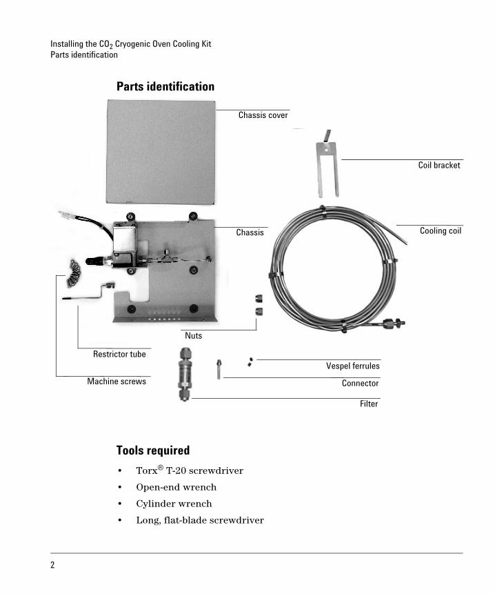
Parts identification
Tools required
• Torx® T-20 screwdriver
• Open-end wrench
• Cylinder wrench
• Long, flat-blade screwdriver
Chassis cover
Coil bracket
Cooling coil
Filter
Connector
Vespel ferrules
Machine screws
Restrictor tube
Chassis
Nuts
2
Installing the CO2 Cryogenic Oven Cooling KitOverview
Overview
Caution Before continuing, read the safety information at the end of this document.
1. Disconnect the GC.
2. Install the inlet if you will be using a cool on-column inlet with cryo blast or PTV inlet with cryo cooling.
3. Open the GC.
4. Install the chassis.
5. Install the restrictor tube.
6. Install the cooling coil.
7. Install the chassis cover.
8. Install the coolant filter.
9. Close the GC.
10. Connect the cryogenic coolant supply.
11. Return the GC to operating condition.
Disconnect the GC
WARNING Pressurized liquid CO2 is a hazardous material. Take precautions to protect personnel from high pressures and low temperatures. CO2 in high concentrations is toxic to humans; take precautions to prevent hazardous concentrations. Consult your local supplier for recommended safety precautions and delivery system design.
WARNING Do not use copper tubing or thin-wall stainless steel tubing with liquid CO2. Both harden at stress points and may explode.
Caution Liquid CO2 should not be used as a coolant for temperatures below –40°C because the expanding liquid may form solid CO2—dry ice—in the GC oven. If dry ice builds up in the oven, it can seriously damage the GC.
3
Installing the CO2 Cryogenic Oven Cooling KitInstall the inlet
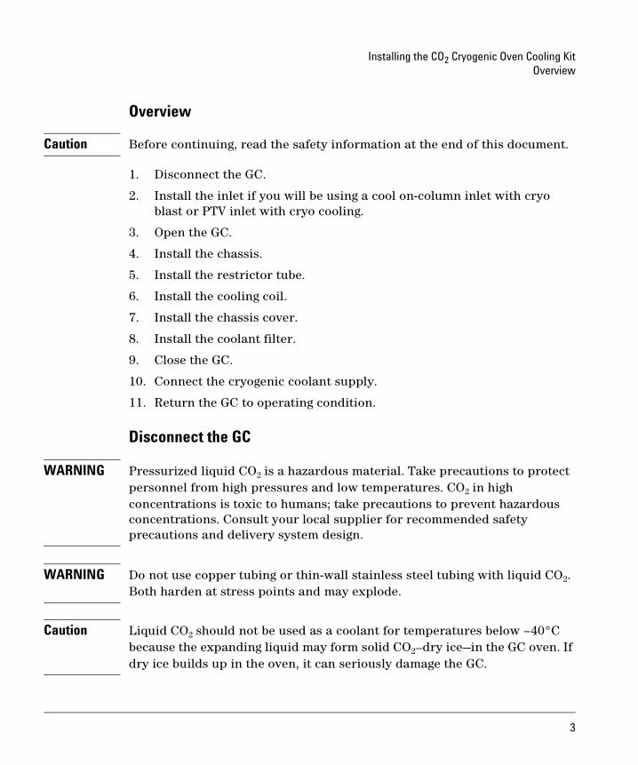
1. Turn off the GC and unplug the power cord. Allow time for all heated zones to cool.
2. Open the lid. If a column is installed, disconnect it at the detector end. Remove the nut warmer, insulation, and capillary adapter, if present. Close the lid.
3. Turn off all gases at their sources. Disconnect the carrier and detector gas tubing from the back panel of the instrument.
Install the inlet
See the installation sheet for the particular inlet you are using to learn how to install it.
Disconnect gas supply tubingfrom these fittings
4
Installing the CO2 Cryogenic Oven Cooling KitOpen the GC
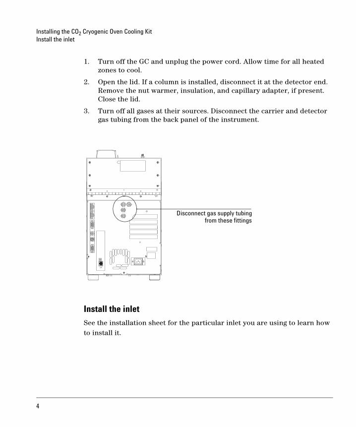
Open the GC1. Open the lid and locate the counterbalance cam in the left rear corner
under the lid. Keeping the lid open with one hand, loosen the screw on the right side of the cam and lower the stop plate (on the right side of the counterbalance cam).
2. Raise the lid until it is stopped by the safety cable.
3. Raise the stop plate and tighten the screw to lock the lid in the upright service position.
WARNING The lid is heavy. Always lock the lid when it is in the service position.
Counterbalance cam
5
Installing the CO2 Cryogenic Oven Cooling KitOpen the GC
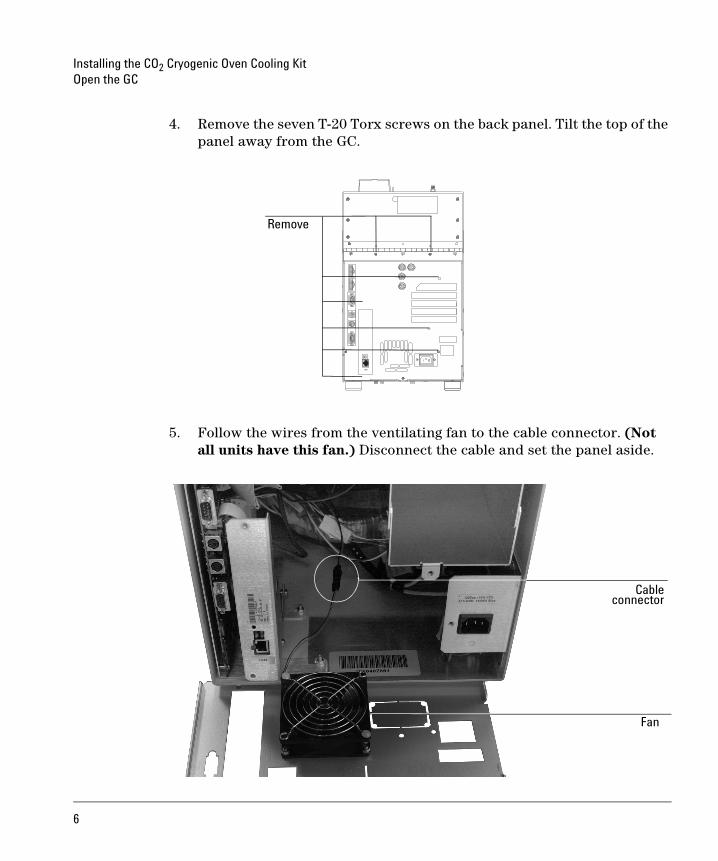
4. Remove the seven T-20 Torx screws on the back panel. Tilt the top of the panel away from the GC.
5. Follow the wires from the ventilating fan to the cable connector. (Not all units have this fan.) Disconnect the cable and set the panel aside.
Remove
Cableconnector
Fan
6
Installing the CO2 Cryogenic Oven Cooling KitOpen the GC
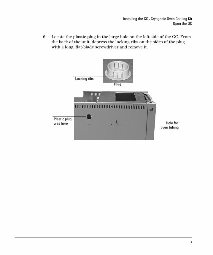
6. Locate the plastic plug in the large hole on the left side of the GC. From the back of the unit, depress the locking ribs on the sides of the plug with a long, flat-blade screwdriver and remove it.
Plug
Locking ribs
Hole forPlastic plugwas here
oven tubing
7
Installing the CO2 Cryogenic Oven Cooling KitInstall the chassis
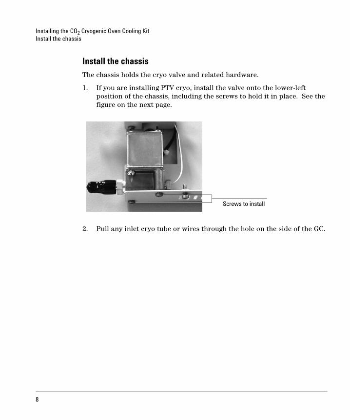
Install the chassis
The chassis holds the cryo valve and related hardware.
1. If you are installing PTV cryo, install the valve onto the lower-left position of the chassis, including the screws to hold it in place. See the figure on the next page.
2. Pull any inlet cryo tube or wires through the hole on the side of the GC.
Screws to install
8
Installing the CO2 Cryogenic Oven Cooling KitInstall the restrictor tube
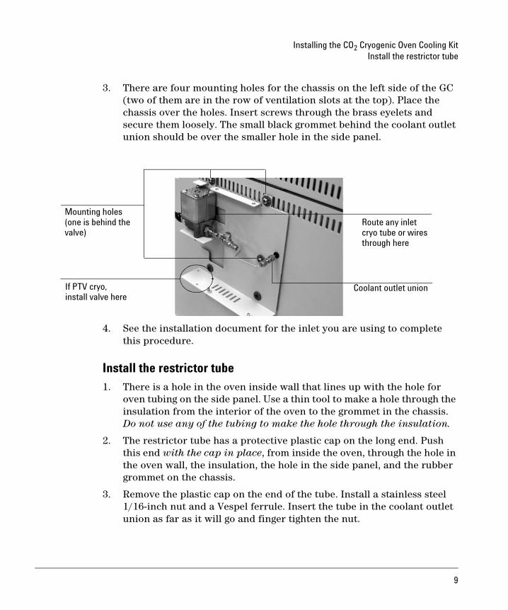
3. There are four mounting holes for the chassis on the left side of the GC (two of them are in the row of ventilation slots at the top). Place the chassis over the holes. Insert screws through the brass eyelets and secure them loosely. The small black grommet behind the coolant outlet union should be over the smaller hole in the side panel.
4. See the installation document for the inlet you are using to complete this procedure.
Install the restrictor tube1. There is a hole in the oven inside wall that lines up with the hole for
oven tubing on the side panel. Use a thin tool to make a hole through the insulation from the interior of the oven to the grommet in the chassis. Do not use any of the tubing to make the hole through the insulation.
2. The restrictor tube has a protective plastic cap on the long end. Push this end with the cap in place, from inside the oven, through the hole in the oven wall, the insulation, the hole in the side panel, and the rubber grommet on the chassis.
3. Remove the plastic cap on the end of the tube. Install a stainless steel 1/16-inch nut and a Vespel ferrule. Insert the tube in the coolant outlet union as far as it will go and finger tighten the nut.
Route any inlet
Coolant outlet union
Mounting holes
cryo tube or wiresthrough here
If PTV cryo, install valve here
(one is behind the valve)
9
Installing the CO2 Cryogenic Oven Cooling KitInstall the cooling coil
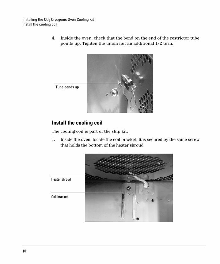
4. Inside the oven, check that the bend on the end of the restrictor tube points up. Tighten the union nut an additional 1/2 turn.
Install the cooling coil
The cooling coil is part of the ship kit.
1. Inside the oven, locate the coil bracket. It is secured by the same screw that holds the bottom of the heater shroud.
Tube bends up
Heater shroud
Coil bracket
10
Installing the CO2 Cryogenic Oven Cooling KitInstall the cooling coil
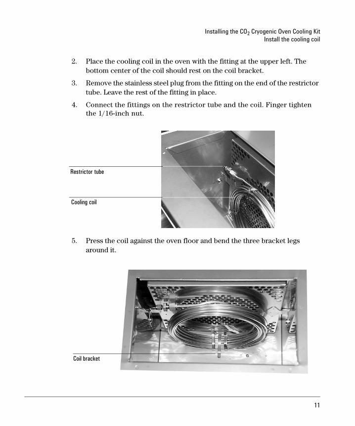
2. Place the cooling coil in the oven with the fitting at the upper left. The bottom center of the coil should rest on the coil bracket.
3. Remove the stainless steel plug from the fitting on the end of the restrictor tube. Leave the rest of the fitting in place.
4. Connect the fittings on the restrictor tube and the coil. Finger tighten the 1/16-inch nut.
5. Press the coil against the oven floor and bend the three bracket legs around it.
Cooling coil
Restrictor tube
Coil bracket
11
Installing the CO2 Cryogenic Oven Cooling KitInstall the chassis cover
6. Check that:
• The restrictor tube enters the oven and turns upward.
• The restrictor tube is connected to the coil and the fittings are finger tight.
• The coil is near to, but makes minimal contact with the heater shroud.
7. Tighten the nut on the restrictor tube 1/2 turn past finger tight. Use open-end and cylinder wrenches.
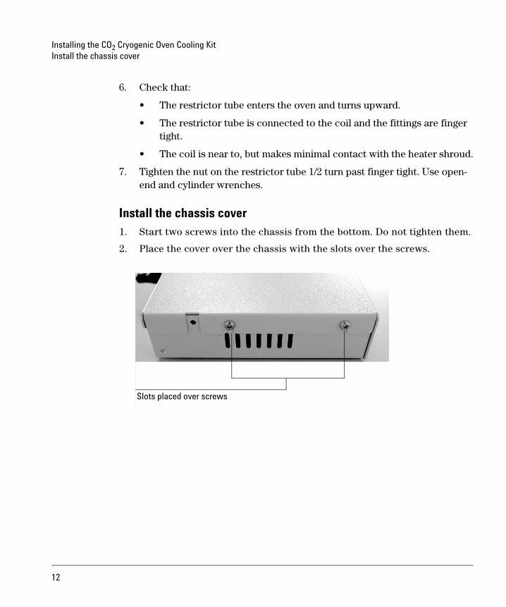
Install the chassis cover1. Start two screws into the chassis from the bottom. Do not tighten them.
2. Place the cover over the chassis with the slots over the screws.
Slots placed over screws
12
Installing the CO2 Cryogenic Oven Cooling KitInstall the coolant filter
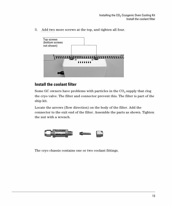
3. Add two more screws at the top, and tighten all four.
Install the coolant filter
Some GC owners have problems with particles in the CO2 supply that clog
the cryo valve. The filter and connector prevent this. The filter is part of the ship kit.
Locate the arrows (flow direction) on the body of the filter. Add the connector to the exit end of the filter. Assemble the parts as shown. Tighten the nut with a wrench.
The cryo chassis contains one or two coolant fittings.
Top screws
not shown)(bottom screws
13
Installing the CO2 Cryogenic Oven Cooling KitInstall the coolant filter
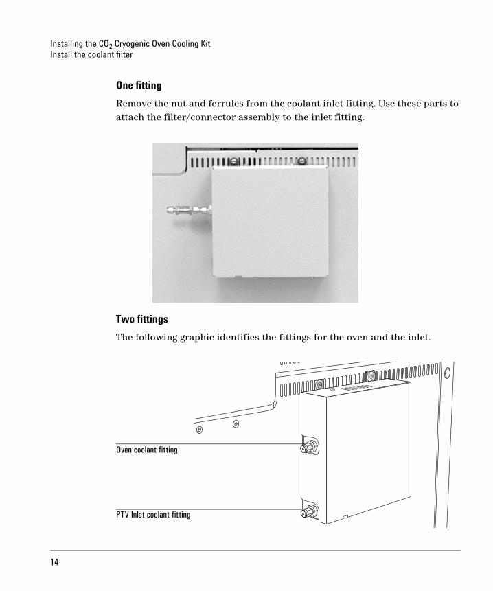
One fitting
Remove the nut and ferrules from the coolant inlet fitting. Use these parts to attach the filter/connector assembly to the inlet fitting.
Two fittings
The following graphic identifies the fittings for the oven and the inlet.
Oven coolant fitting
PTV Inlet coolant fitting
14
Installing the CO2 Cryogenic Oven Cooling KitClose the GC
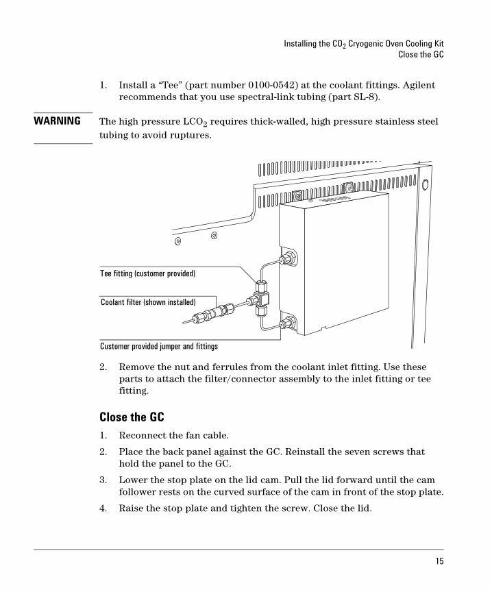
1. Install a “Tee” (part number 0100-0542) at the coolant fittings. Agilent recommends that you use spectral-link tubing (part SL-8).
WARNING The high pressure LCO2 requires thick-walled, high pressure stainless steel tubing to avoid ruptures.
2. Remove the nut and ferrules from the coolant inlet fitting. Use these parts to attach the filter/connector assembly to the inlet fitting or tee fitting.
Close the GC1. Reconnect the fan cable.
2. Place the back panel against the GC. Reinstall the seven screws that hold the panel to the GC.
3. Lower the stop plate on the lid cam. Pull the lid forward until the cam follower rests on the curved surface of the cam in front of the stop plate.
4. Raise the stop plate and tighten the screw. Close the lid.
Coolant filter (shown installed)
Tee fitting (customer provided)
Customer provided jumper and fittings
15
Installing the CO2 Cryogenic Oven Cooling KitConnect the cryogenic coolant supply
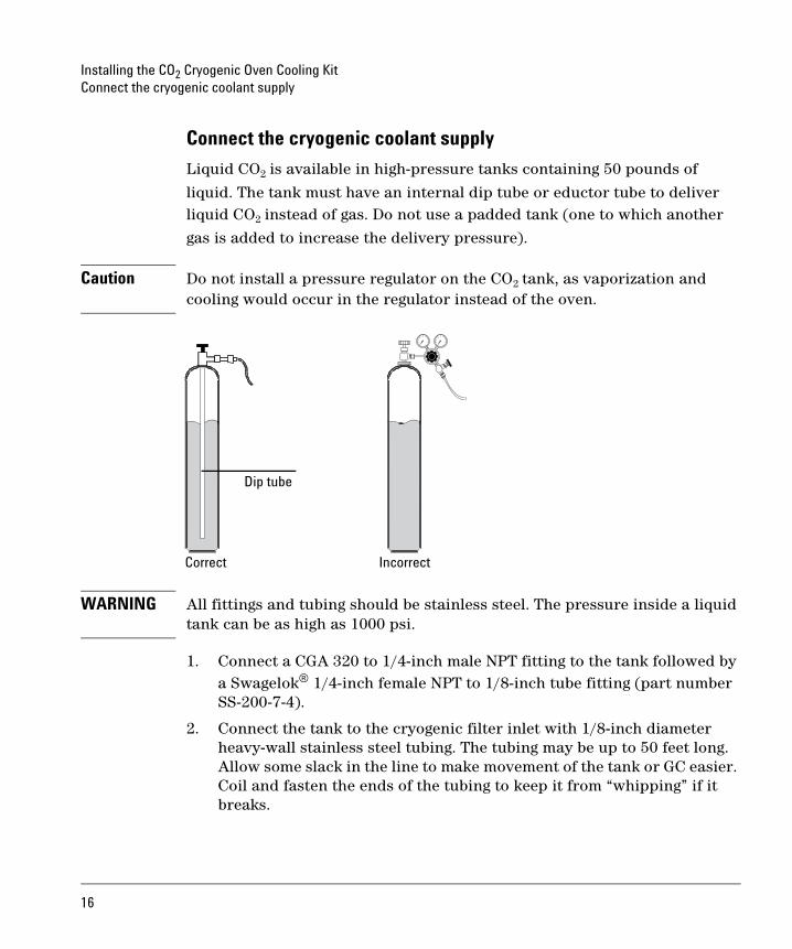
Connect the cryogenic coolant supply
Liquid CO2 is available in high-pressure tanks containing 50 pounds of
liquid. The tank must have an internal dip tube or eductor tube to deliver liquid CO2 instead of gas. Do not use a padded tank (one to which another
gas is added to increase the delivery pressure).
Caution Do not install a pressure regulator on the CO2 tank, as vaporization and cooling would occur in the regulator instead of the oven.
WARNING All fittings and tubing should be stainless steel. The pressure inside a liquid
tank can be as high as 1000 psi.
1. Connect a CGA 320 to 1/4-inch male NPT fitting to the tank followed by a Swagelok® 1/4-inch female NPT to 1/8-inch tube fitting (part number SS-200-7-4).
2. Connect the tank to the cryogenic filter inlet with 1/8-inch diameter heavy-wall stainless steel tubing. The tubing may be up to 50 feet long. Allow some slack in the line to make movement of the tank or GC easier. Coil and fasten the ends of the tubing to keep it from “whipping” if it breaks.
Correct Incorrect
Dip tube
16
Installing the CO2 Cryogenic Oven Cooling KitRestore the GC to operating condition
Restore the GC to operating condition1. Install the capillary adapter, if used.
2. Restore the column connection.
3. Restore carrier and other gases to the instrument.
4. Restore power.
5. Apply your normal operating pressures. Leak-check the manifold, back panel, and column fittings.
17
permission is prohibited, except as allowed under the copyright laws.
© Agilent Technologies, Inc. 2004
All Rights Reserved. Reproduction, adaptation, or translation without
Part number G2625-90117First Edition, May 2004
Printed in USA
Agilent Technologies, Inc.2850 Centerville RoadWilmington, DE 19808-1610
Safety SymbolsWarnings in the manual or on the instrument must be observed during
comply with these precautions violates safety standards of design and
liability for the customer’s failure to comply with these requirements.
In the manualA warning calls attention to a condition or possible situation that could
A caution calls attention to a condition or possible situation that could
all phases of operation, service, and repair of this instrument. Failure to
the intended use of the instrument. Agilent Technologies assumes no
cause injury to the user.
damage or destroy the product or the user’s work.
AcknowledgementsTorx® is a U.S. registered trademark of Textron, Inc. Swagelok® is a U.S. registered trademark of the Swagelok Company.
Replaces part number G2625-90107
G2625-90117
On the instrument
See accompanying instructions for more information.
Indicates a hot surface.
Indicates hazardous voltages.
Indicates earth (ground) terminal.
Indicates explosion hazard.
Indicates radioactivity hazard.
Indicates electrostatic discharge hazard.
Indicates pinch hazard.