Embed Size (px)
Citation preview

s1
Installing the Agilent CE ESI-MS
Sprayer Kit (G1607A)
This note describes how to connect an Agilent capillary electrophoresis system to an Agilent mass selective detector (G1946A). Typical method parameters are given to analyze a simple test sample. Detailed information on how to set up the Agilent mass selective detector can be found in the System
Installation Manual for the Agilent 1100 LC/MSD.
Copyright Agilent Technologies 2000 1

Installing the Agilent CE ESI-MS Sprayer Kit (G1607A)Requirements
Requirements
Equipment
❏ Agilent CE system with serial number greater than 3534G00644 or upgraded to CE-MS capability.
❏ Agilent CE-MS Adapter kit (G1603A).
❏ Agilent mass selective detector (G1946A) with Agilent API-Electrospray source (G1948A).
❏ A syringe pump which can deliver a precise flow rate of 1–5 µl/min or a Agilent 1100 Series pump with an optional Agilent 1100 Series vacuum degasser to add the sheath liquid.
❏ The Agilent CE-ESI-MS sprayer kit, containing the items shown in Table 1.
Table 1 Contents of Agilent CE-ESI-MS Sprayer Kit
Description Quantity Part Number
ES needle assembly 1 G1607-60041
CE-MS Neb. cover 1 G1607-60034
Hex key set II 1 8710-2164
DIN3115 screwdriver 1 5022-2142
CE-ESI sprayer 1 G1607-60001
Splitter assembly 1 G1607-60000
Ferrule 360 µm 1 5022-2141
Nut fingertight 2 0100-1543
Flex loc element 2 1520-0401
Screw M4 x 0.7 2 0515-0982
2

Installing the Agilent CE ESI-MS Sprayer Kit (G1607A)Requirements
Chemicals and Parts Needed
❏ 1 N sodium hydroxide (not supplied, for example, part number 5062-8576).
❏ CE grade water (not supplied, for example, part number 5062-8578).
❏ HPLC grade methanol (not supplied).
❏ 100 mM ammonium acetate (5 ml ampules containing 1.9 g ammonium acetate in 20/80 (v/v) methanol/water. part number 8500-4410, Thermospray Ionization Reagent. Included in the Agilent sprayer kit.
❏ Test sample quinine sulfate dihydrate (part number 5063-6590). Included in the Agilent sprayer kit.
❏ CE-MS capillary o.d. 360 µm, i.d. 50 µm (part number G1600-67311, one set is included in the Agilent CE-MS adapter kit.
❏ CE-MS alignment interface (part number G1600-60400, one interface is included in the Agilent CE-MS adapter kit).
Gasket 2 G1607-20030
Fitting 2 0100-1544
Instructions 1 G1600-90106
Ion kit (ammonium acetate) 1 8500-4410
CE-MS test sample 1 5063-6590
Table 1 Contents of Agilent CE-ESI-MS Sprayer Kit, continued
Description Quantity Part Number
3
Installing the Agilent CE ESI-MS Sprayer Kit (G1607A)Preparation of Buffers and Test Sample
Preparation of Buffers and Test Sample
The following solutions have to be prepared:
❏ 1 N sodium hydroxide (initial conditioning of the capillary).
❏ 1 ml water (initial conditioning of the capillary).
❏ 10 mM ammonium acetate pH 6.9 (running buffer).
❏ 5 mM ammonium acetate in 50% methanol (sheath liquid).
❏ 1 mg/ml quinine sulfate dihydrate in water (test sample).
NOTE Solvents used for CE should be filtered through a 0.2 µm filter prior to use.
4

Installing the Agilent CE ESI-MS Sprayer Kit (G1607A)Preparation of Buffers and Test Sample
Test Sample
1 Weigh 1 mg of the test sample in a 2 ml Eppendorf cup.
2 Add 1 ml water.
3 Stir until the compound is completely dissolved (place the vial for 30 min in a mixer or for 15 min in an ultrasonic bath).
4 Prepare a CE vial with the test solution (1 ml in a glass vial or 500 µl in a polypropylene, PP, vial).
Solvents Used for Initial Conditioning
1 Prepare 1 vial with 1 N sodium hydroxide (300 µl in a PP vial).
2 Prepare 1 vial with water (1 ml in glass vial or 500 µl in PP vial).
Running Buffer
1 Dilute the content of one 5 ml ampule (containing 1.9 g ammonium acetate in 20/80 (v/v) methanol/water) in 245 ml water. This gives a stock solution of 100 mM ammonium acetate pH 6.9, 0.4% (v/v) methanol.
2 Dilute the stock solution to 1:10.
3 Prepare two vials (1 ml in glass vials or 500 µl in PP vials) with buffer.
Sheath Liquid
1 Mix 225 ml of CE grade water with 250 ml of methanol.
2 Add 25 ml of the 100 mM ammonium acetate stock solution.
3 Stir thoroughly.
4 Fill the sheath liquid in solvent bottle A of the Agilent 1100 Series pumping system. In case a syringe pump is used to deliver the sheath liquid, fill a syringe.
NOTE Prepare fresh sheath liquid at least once a week.
Prepare the test sample fresh prior to use.
5

Installing the Agilent CE ESI-MS Sprayer Kit (G1607A)Preparing the Agilent 1100 Series Pump and Vacuum Degasser
Preparing the Agilent 1100 Series Pump
and Vacuum Degasser
The following steps have to be done if the pump and degasser are used.
❏ Install the pump and the degasser (optional) as described in their installation documentation. Otherwise an infusion pump has to be installed and connected.
❏ The sheath flow splitter (included in the Agilent CE-MS sprayer kit) has to be connected to the pump outlet. The following section describes the setup.
Figure 1 The Sheath Flow Splitter
From pum p
Recycle or w aste
1:100 Splitter
RECYCLE
O ut to CE-ESI-M S interface
OUT
G1607-60000
6

Installing the Agilent CE ESI-MS Sprayer Kit (G1607A)Preparing the Agilent 1100 Series Pump and Vacuum Degasser
1 Install the flow splitter in the isocratic pump. Put the 2 rubber plugs from the Agilent sprayer kit into the sheet metal as shown below and use the two screws also included to mount the splitter.
2Connect the tubing labeled pump to the pump outlet. The waste tubing may be drawn back into the sheath liquid bottle to reuse the solvent).
3 Still leave the tubing labeled Out disconnected from the sprayer but place its end in a beaker. It will be connected later.
7

Installing the Agilent CE ESI-MS Sprayer Kit (G1607A)Preparing the Agilent 1100 Series Pump and Vacuum Degasser
4 Fill the sheath liquid in solvent bottle A of the 1100 pumping system. Connect the tubing of bottle A to the degasser (optional). Open the purge valve and flush the pump at 2 ml/min (100% A) for 10 min. Reduce the flow rate to 0.4 ml/min and close the purge valve. The splitter splits the sheath liquid in the ratio 1:100, so the sheath liquid flow rate will be 4 µl/min.If no degasser is in use the sheath liquid MUST be vacuum degassed prior use, and the flush time may be shorter.
5 The backpressure at 0.4 ml/min is approximately 40 bar.
Setup Pump Parameters
• Flow: 0.400 ml/min (1:100 flow splitter = 0.004 ml/min)
• %B: 0
• Active channel: A
• Max pressure/flow: 400 bar
8

Installing the Agilent CE ESI-MS Sprayer Kit (G1607A)Preparing the Agilent CE System
Preparing the Agilent CE System
Please refer to the section “Setting up the Instrument” in the chapter ‘”Online CE-ESI-MS with the Agilent CE system” of the Agilent CE User’s Guide to make the necessary modifications. Please refer to the System Installation Manual for the Agilent 1100 LC/MSD to prepare the MSD.
If both the LC-MS and the CE-MS instrumentation are intended to be controlled from the same PC, the configuration editor has to be changed so that the MSD of the running software gets the GPIB address 0 and the MSD of the silent software gets GPIB address 1.
If the Agilent CE Instrument is to be used without a DAD, perform the following steps:
Switch the lamp off, close the Agilent ChemStation, go to configuration editor and delete the DAD from the Agilent CE instrument. Save the new settings. Remove the remote cable from the DAD. Open the Agilent ChemStation.
NOTE Method files which have been created in the version without a DAD, will come up with DAD default settings when reopened in the version with DAD. Method files which have been created in the version with DAD and are opened and saved in the version without DAD will keep the original DAD settings.
To avoid siphoning the Agilent CE system inlet vial should be at the same height to the sprayer tip of Agilent mass selective detector. Both instruments should be placed close to each other to allow a short capillary length.
9

Installing the Agilent CE ESI-MS Sprayer Kit (G1607A)Preparing the Agilent CE System
Figure 2 CE and MSD Connected to Each Other
10

Installing the Agilent CE ESI-MS Sprayer Kit (G1607A)Preparing the Capillary
Preparing the Capillary
To have a short capillary connection to the Agilent mass selective detector, 45 cm have to be cut off from the long end of the CE-MS capillary. The remaining length is now about 80 cm.
NOTE The precision of the spray depends on the quality of the cut. Ordinary scoring devices gather and rip the coating of the capillary. Jagged edges are left that prevent a perfect spray and can act as adsorptive sites for sample components.
Figure 3 Cutting the Capillary
1 Place the capillary over large radius surface under slight tension.
2 Hold the scribe (delivered with the capillary) at an angle of approximately 30° to the capillary.
3 Draw edge of the scribe across the capillary penetrating the polyimide.
4 Pull the capillary horizontal until it breaks. If the capillary will not break, the polyimide has not been cut. Repeat above steps.
5 Install the capillary into the MS cassette (see chapter “Online CE-MS” in your User’s Guide).
6 Insert the MS cassette in the Agilent CE system.
7 Insert the capillary end in the CE-MS sprayer as described in “Preparing the Agilent Mass Selective Detector” on page 12.
11

Installing the Agilent CE ESI-MS Sprayer Kit (G1607A)Preparing the Agilent Mass Selective Detector
Preparing the Agilent Mass Selective
Detector
The API-Electrospray source must be installed. Please refer to appropriate documentation. It is assumed that the MSD has been successfully tuned for single charged molecules (atunes.tun).
Inserting and Adjusting the CE Capillary in the Agilent
CE-ESI-MS Sprayer
Figure 4 The Agilent CE-ESI-MS Sprayer
12

Installing the Agilent CE ESI-MS Sprayer Kit (G1607A)Preparing the Agilent Mass Selective Detector
1 Remove the protection plastic tube from the sprayer tip. Turn the adjustment screw counterclockwise (+ direction) until its mechanical stop. Then turn two complete turns clockwise (- direction).
2 Open the fitting for the CE and insert the capillary. Fix the capillary so that it still can be moved up or down. The capillary should be aligned flat with the sprayer tip. You can use your finger nail. Tighten the fitting screw tight enough to keep the capillary in place.
3 Turn the adjustment screw 1/4 turn counter clockwise (2 marks in + direction). Finally the capillary should protrude approximately 0.1 mm out of the sprayer tip
13

Installing the Agilent CE ESI-MS Sprayer Kit (G1607A)Installing the Agilent CE-ESI-MS Sprayer
Installing the Agilent CE-ESI-MS Sprayer
1 Connect the nebulizing gas and the sheath liquid to the CE sprayer.
2 Remove the cover of the ion source. Carefully insert the CE sprayer into the electrospray chamber of the MSD. Do not touch the electrospray chamber with the sprayer tip, because it can damage the sprayer tip easily. Do not hold the sprayer at the adjustment screw while inserting it into the ion source. This can misalign the sprayer.
14

Installing the Agilent CE ESI-MS Sprayer Kit (G1607A)Installing the Agilent CE-ESI-MS Sprayer
3 Mount the ion-source cover included in the Agilent sprayer kit.
15

Installing the Agilent CE ESI-MS Sprayer Kit (G1607A)Method to Analyze the Test Sample
Method to Analyze the Test Sample
The parameters given in this section are typical for the analyzed test sample. However, they might have to be adapted when other samples are analyzed. Typical settings for the spray chamber parameters are:
Drying gas: 6–10 l/minDrying gas temperature: 100–300 °CNebulizing gas: 10–20 psiHV (positive mode): 3.5–4 kVHV (negative mode): 3–3.5 kV
Prior to first use, a new capillary should be properly conditioned. A procedure including a 5 min 1N NaOH flush, followed by a 10 min flush with water and a 20 min flush with run buffer is appropriate for the analysis of the test sample. There is no need to remove the capillary from the system prior to this procedure provided the sheath liquid is running.
Vial table: 1 = 1 N NaOH, 2 = water, 5, 6 = run buffer (10 mM ammonium acetate, pH 6.9, 0.4% methanol), 7 = 1 test sample (1 mg/ml quinine sulfate dihydrate).
The method described here is also stored in the Agilent ChemStation for CE-MS under C:\HPCHEM\1\methods\cems\quinine.m
HIGH PERFORMANCE CAPILLARY ELECTROPHORESIS
CE mode: CE-MS
Home values:Lift Offset 4Cassette Temperature 20 °CInlet Home Vial 5: bufferOutlet Home Vial none
Replenishment and Preconditioning:serial processing
Replenishment Entries:No Replenishment used
Preconditioning Entries:Function Parameter1 FLUSH 5.00 min, I:6, O:don’t care
Postcondition Entries:No Postcondition used
16

Installing the Agilent CE ESI-MS Sprayer Kit (G1607A)Method to Analyze the Test Sample
Electric:Electric OnPolarity PositiveVoltage 0.00 kVCurrent 50.00 µAPower System LimitLow Current Limit 0.00 µA
Injection Table Entries:Function Parameter1 PRESSURE 50.0 mbar, 2.0 sec, I:InjectVial, O:don’t care2 PRESSURE 50.0 mbar, 2.0 sec, I:InHomeVial, O:don’t care
Store Data:Collect current: Yes
Time entries:Stoptime 10.00 minPosttime Off
Timetable:Time [min] Function Parameter0.3 VOLTAGE 27.00 kV
DIODE ARRAY DETECTOR
Settings:Stop Time no LimitPost Time OffResponse Time 0.2 secPeakwidth >0.01 minPrerun Autobalance OnPostrun Autobalance Off
Spectrum:Store All in peakFrom 190 nmTo 450 nmTreshold 2.00 mAU
Signals:Store Signal,Bw Reference,Bw [nm]
A: Yes 254,16 450,80
17

Installing the Agilent CE ESI-MS Sprayer Kit (G1607A)Method to Analyze the Test Sample
Agilent 1100 ISOCRATIC PUMP 1
Control:Flow 0.400 ml/minStoptime No LimitPosttime Off
Solvents:Solvent A 100.0% (5 mM Ammac pH 6.9 in 50% MeOH)
Pressure Limits:Minimum Pressure 0 barMaximum Pressure 400 bar
Auxiliary:Maximal Flow Ramp 100.00 ml/min^2Compressibility 75*10^-6/barMinimal Stroke 100 µl
MASS SPECTROMETER DETECTOR
General Information:Use MSD EnabledIonization Mode API-ESPolarity PositiveStopTime asPumpPeakwidth 0.12 minScan Speed Override DisabledFragmentor Ramp Disabled
Tune File atunes.tunTime Filter EnabledData Storage Condensed
Scan Parameters:Time 0 minMass range 150-350 m/zGain 3Fragmentor 65 VThreshold 50Stepsize 0.10
Gas Temp 130 C maximum 350 CDryingGas 10 l/min maximum 13.0 l/minNeb Pres 10 psig maximum 60 psigVCap 4000 V
Establish and run a sequence with 5 consequent injections from the vial with the test sample.
18

Installing the Agilent CE ESI-MS Sprayer Kit (G1607A)Method to Analyze the Test Sample
Due to the equilibration of the system the first run of the sequence may not be successful and should be discarded. The following runs should result in UV and MS traces similar to those shown in Figure 5.
Figure 5 UV and MS Traces
MS spectra taken from the peak in the MS trace should be similar to the one shown in Figure 6.
Figure 6 MS Spectra
MW: 325, 326
19

Installing the Agilent CE ESI-MS Sprayer Kit (G1607A)Storing the CE-MS Capillary, the Sheath Flow Splitter and the CE-MSD sPrayer Needle After Usage
Storing the CE-MS Capillary, the Sheath
Flow Splitter and the CE-MSD sPrayer
Needle After Usage
To avoid plugging of the capillary, the sheath flow splitter and the CE-MSD sprayer needle need to be cleaned if not in use.
Cleaning of the Sheath Flow Splitter and the CE-MSD
Sprayer Needle
1 Replace the sheath liquid bottle with a bottle filled with water.
2 Leave the CE-MS capillary, the sheath flow splitter and the nebulizing gas connected.
3 Prime the pump and flush for 10 minutes pump water through the sheath flow splitter and CE-MSD sprayer needle.
4 Replace the water in the sheath liquid bottle with iso-propanol.
5 Prime the pump and flush for 10 minutes pump iso-propanol through the sheath flow splitter and CE-MSD sprayer needle.
Storing the CE-MS capillary
1 Flush the capillary with water for 10 minutes.
2 Insert an empty vial with a cap into the tray and flush the capillary with air for 10 minutes.
3 The capillary can now be removed and stored.
20

Installing the Agilent CE ESI-MS Sprayer Kit (G1607A)Maintenance
Maintenance
In general the CE-MSD sprayer needs little maintenance. But it may happen that from time-to-time or in case of a problem some parts need to be replaced. The parts shown in Table 2 can be exchanged:
Table 2 Parts for Maintenance or Repair (see Figure 7)
Item Number Description Part number
1 Sprayer body No part number
2 Sprayer head No part number
3a, 3b Gasket G1607-20030
4 0-ring 0905-1022
5 Spray needle G1607-60041
6 Spring 5022-2140
7 Screw body G1607-20029
8a, 8b Seal holding screw G1607-20022
9 Protection tube for the sprayer 0890-0581
Not shown PEEK screw capillary and nebulizing gas 0100-1543
Not shown PEEK ferrule capillary 5022-2141
Not shown PEEK ferrule nebulizing gas 0100-1544
21

Installing the Agilent CE ESI-MS Sprayer Kit (G1607A)Maintenance
Figure 7 The CE-MSD Sprayer
The Agilent CE-ESI-MS Sprayer needs in general little maintenance. Following parts can be exchanged if necessary.
Replacing the Sprayer Gasket
(item 3a, 3b, part number G1607-20030)
A leaky gasket can generate an unstable MSD signal. The gasket can be damaged if the flow rate of the sheath liquid exceeds than 200 µl/min.
A set of gaskets is provided with the Agilent CE-ESI-MS sprayer kit.
Parts Needed
❏ Hex key 2 mm
❏ Hex key 1.3 mm
❏ Gasket (part number G1607-20030)
7
6
2
3
8
5
3
1
4
9
a
b
8a8b
22

Installing the Agilent CE ESI-MS Sprayer Kit (G1607A)Maintenance
Steps to Exchange the Gasket
1 Disconnect the nebulizing gas, the sheath liquid tube and the CE-MS capillary from the sprayer.
2 Remove the CE-MS sprayer from the MSD.
3 Open the two body screws (7). Be careful not to lose the attached springs (6).
4 Unscrew the sprayer head (2) from the sprayer body (1).
23
Installing the Agilent CE ESI-MS Sprayer Kit (G1607A)Maintenance
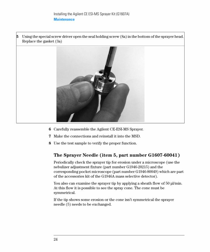
6 Carefully reassemble the Agilent CE-ESI-MS Sprayer.
7 Make the connections and reinstall it into the MSD.
8 Use the test sample to verify the proper function.
The Sprayer Needle (item 5, part number G1607-60041)
Periodically check the sprayer tip for erosion under a microscope (use the nebulizer adjustment fixture (part number G1946-20215) and the corresponding pocket microscope (part number G1946-80049) which are part of the accessories kit of the G1946A mass selective detector).
You also can examine the sprayer tip by applying a sheath flow of 50 µl/min. At this flow it is possible to see the spray cone. The cone must be symmetrical.
If the tip shows some erosion or the cone isn’t symmetrical the sprayer needle (5) needs to be exchanged.
5 Using the special screw driver open the seal holding screw (8a) in the bottom of the sprayer head. Replace the gasket (3a)
24

Installing the Agilent CE ESI-MS Sprayer Kit (G1607A)Maintenance
Steps to Exchange the Sprayer Capillary
1 Disconnect the nebulizing gas, the sheath liquid tube and the CE-MS capillary from the sprayer.
2 Remove the CE-MS sprayer from the MSD.
4 Open the two body screws (7). Be careful not to lose the attached springs (6).
5 Unscrew the sprayer head (2) from the sprayer body (1).
25

Installing the Agilent CE ESI-MS Sprayer Kit (G1607A)Maintenance
8 Carefully reassemble the Agilent CE-ESI-MS Sprayer.
9 Check, if the sprayer needle juts out about 0.1–0.2 mm (ca. 1/3 of its diameter) from the sprayer tip. Use the nebulizer adjustment fixture (part number G1946-20215) and the corresponding pocket microscope (part number G1946-80049) which are part of the accessories kit of the G1946A MSD. If necessary readjust the sprayer needle.
10 Make the connections and reinstall it into the MSD.
11 Use the test sample to verify the proper function.
NOTE A new Agilent CE-ESI-MS Sprayer is already preadjusted. Therefore do not open the hex-key screws on the body part.
Check, if the sprayer needle protrudes about 0.1–0.2mm (~ 1/3 × d) from the sprayer tip. Use the nebulizer adjustment fixture (part number G1946-20215) and the corresponding pocket microscope (part number G1946-80049) which are part of the accessories kit of the Agilent MSD. If necessary readjust the sprayer needle.
6 Open the seal holding screw (8b) of the sprayer body.
7 Remove the defective sprayer needle (5). Add a new gasket (3b) and carefully insert the new sprayer needle.
8
5
3 b
b
26

Installing the Agilent CE ESI-MS Sprayer Kit (G1607A)Maintenance
Readjusting the Sprayer Needle
A new Agilent CE-ESI-MS Sprayer is already preadjusted. The sprayer needle should protrude from the sprayer tip about 0.1–0.2mm. This setting gives highest sensitivity and baseline stability. During normal operation there is no need to readjust the sprayer needle. Only readjust the CE-ESI-MS Sprayer if the sprayer needle position differs from the settings above.
27

Installing the Agilent CE ESI-MS Sprayer Kit (G1607A)Maintenance
Steps to Readjust the Sprayer Needle
1 Turn the adjustment screw counterclockwise (+ direction) until its mechanical stop.
2 Open the 3 hex-key screws on the lower adjustment ring by 1/2 turn.
3 During the following adjustment procedure press sprayer head and body part together to remove backlash (see picture above)
4 Turn the lower adjustment ring counterclockwise until the sprayer needle is
28

Installing the Agilent CE ESI-MS Sprayer Kit (G1607A)Maintenance
flat with the sprayer tip.
5 Now turn the lower adjustment screw by 1/4 turn clockwise.
6 Tighten the 3 hex-key screws on the lower adjustment ring again.
Check that the sprayer needle now protrudes about 0.1–0.2mm (~ 1/3 × d) from the sprayer tip. This can be done by using the nebulizer adjustment fixture (part number G1946-20215) and the corresponding pocket microscope (part number G1946-80049) which are part of the accessories kit of the Agilent MSD.
If necessary readjust the sprayer needle.
29

Installing the Agilent CE ESI-MS Sprayer Kit (G1607A)Maintenance
Troubleshooting Matrix
Table 3 Troubleshooting Matrix
What Can Be Seen? Cause Solution
Test sample delayed or not shown in the UV signal
Pressure difference between inlet and outlet of the CE-MS capillary.
Adjust the level of the inlet and outlet of the CE-MS capillary (e.g. height adjustable table). Check for a slight overpressure due to the parameters of the vent system (e.g. drying gas).If possible remove the overpressure situation otherwise apply 50 mbar during run (Timetable of the CE).
MSD signal not stable Capillary not well cut. Cut the capillary again. Make sure the cut is flat and the capillary is not shattered at the end.
Polyimide left at the end. Remove the polyimide by burning it off. Clean that area with iso-propanol.
Capillary not well adjusted
The capillary should be 0.1 mm (2 marks) protrude of the sprayer capillary, if that is not the case readjust the CE-capillary. See “Inserting and Adjusting the CE Capillary in the Agilent CE-ESI-MS Sprayer” on page 12.
Sprayer tip eroded. Exchange the sprayer tip. See “Steps to Exchange the Sprayer Capillary” on page 25.
Sprayer capillary gasket is leaking
Replace the sprayer capillary gasket. See “Steps to Exchange the Gasket” on page 23.
Sheath flow too low. The sheath flow splitter might be plugged. But be aware that 4 µl/min (about1droplet/8 minutes) leaving the restriction capillary is not much!.Backflush the different capillaries of the sheath flow splitter or exchange the flow splitter.
30

Installing the Agilent CE ESI-MS Sprayer Kit (G1607A)Maintenance
31

Installing the Agilent CE ESI-MS Sprayer Kit (G1607A)Maintenance
© Copyright Agilent Technologies 2000Printed in Germany Edition 02/00
Part No. G1600-90117