Embed Size (px)
Citation preview
Installer manualLEK
NIBE™ F2030Air/water heat pump
IHB GB 1540-4 231115

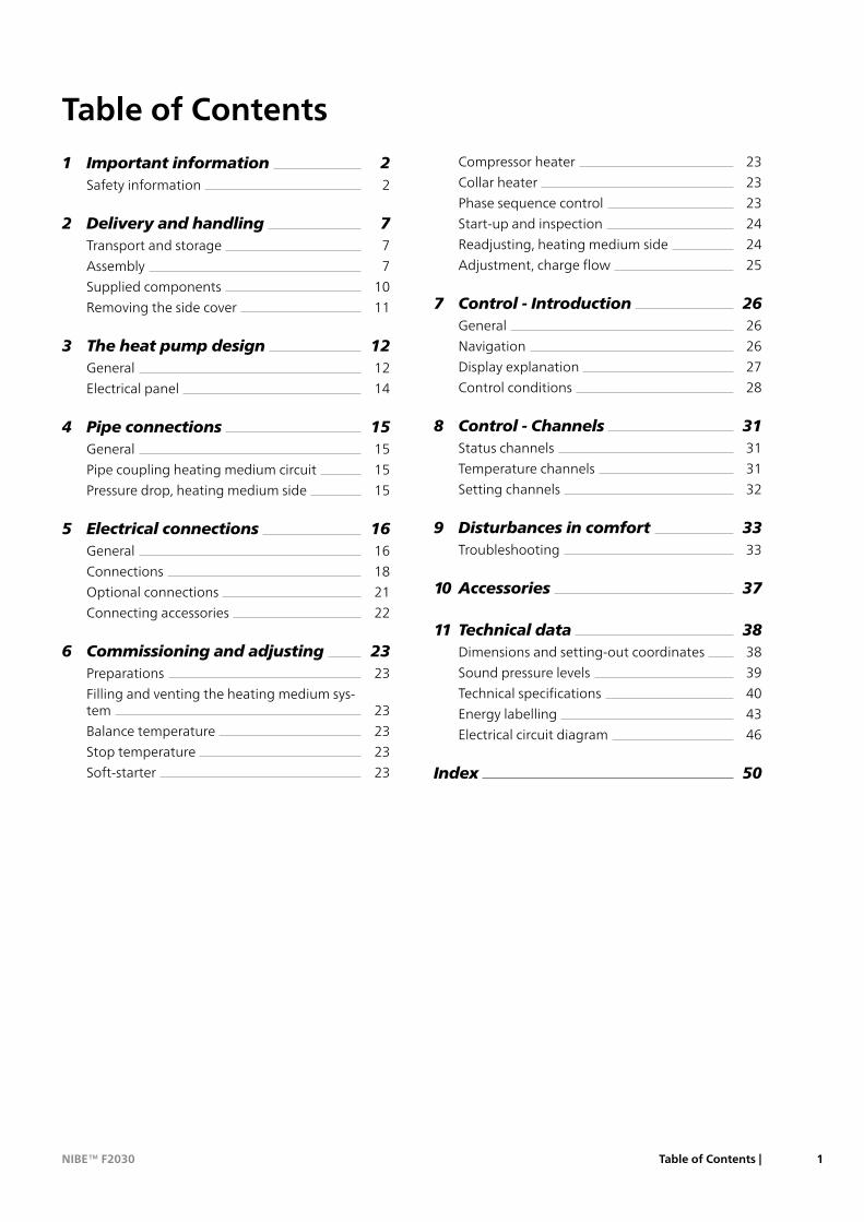
Table of Contents
21 Important information2Safety information
72 Delivery and handling7Transport and storage
7Assembly
10Supplied components
11Removing the side cover
123 The heat pump design12General
14Electrical panel
154 Pipe connections15General
15Pipe coupling heating medium circuit
15Pressure drop, heating medium side
165 Electrical connections16General
18Connections
21Optional connections
22Connecting accessories
236 Commissioning and adjusting23Preparations
23Filling and venting the heating medium sys-tem
23Balance temperature
23Stop temperature
23Soft-starter
23Compressor heater
23Collar heater
23Phase sequence control
24Start-up and inspection
24Readjusting, heating medium side
25Adjustment, charge flow
267 Control - Introduction26General
26Navigation
27Display explanation
28Control conditions
318 Control - Channels31Status channels
31Temperature channels
32Setting channels
339 Disturbances in comfort33Troubleshooting
3710 Accessories
3811 Technical data38Dimensions and setting-out coordinates
39Sound pressure levels
40Technical specifications
43Energy labelling
46Electrical circuit diagram
50Index
1Table of Contents |NIBE™ F2030
Safety informationThis manual describes installation and service proced-ures for implementation by specialists.
This appliance is designed for use in ahome environment and not intendedto be used by persons (including chil-dren) with reduced physical, sensory ormental capabilities, or lack of experi-ence and knowledge, unless they havebeen given supervision or instructionconcerning use of the appliance by aperson responsible for their safety. Thisin accordance to applicable parts of thelow-voltage directive 2006/95/EC, LVD.The appliance is also intended for useby experts or trained users in shops,hotels, light industry, on farms and insimilar environments. This in accordanceto applicable parts of the machinerydirective 2006/42/EC.
Children should be supervised to ensurethat they do not play with the appli-ance.
This is an original instruction manual.Translation is not allowed without ap-proval from NIBE.
Rights to make any design or technicalmodifications are reserved.
©NIBE 2015.
Symbols
NOTE
This symbol indicates danger to machine orperson.
Caution
This symbol indicates important informationabout what you should observe when main-taining your installation.
TIP
This symbol indicates tips on how to facilitateusing the product.
MarkingThe CE marking means that NIBE ensures that theproduct meets all regulations that are placed on itbased on relevant EU directives. The CE mark is obligat-ory for most products sold in the EU, regardless wherethey are made.
NIBE™ F2030Chapter 1 | Important information2
1 Important information
Safety precautions
CautionInstall the system in full accordance with this installationmanual.Incorrect installation can cause bursts, personal injury, waterleaks, refrigerant leaks, electric shocks and fire.
Observe the measurement values before working on thecooling system, especiallywhen installing in small rooms, sothat the limit for the refrigerant's density is not exceeded.Consult an expert to interpret the measurement values. If therefrigerant density exceeds the limit, lack of oxygen can occur inthe event of any leak, which can cause serious accidents.
Use original accessories and the stated components for theinstallation.If parts other than those stated by us are used, water leaks, electricshocks, fire and personal injury may occur as the unit may notwork properly.
Ventilate the working area well – refrigerant leakage mayoccur during service work.If the refrigerant comes into contact with naked flames, poisonousgas is created.
Install the unit in a location with good support.Unsuitable installation locations can cause the unit to fall andcause material damage and personal injury. Installation withoutsufficient support can also cause vibrations and noise.
Ensure that the unit is stable when installed, so that it canwithstand earthquakes and strong winds.Unsuitable installation locations can cause the unit to fall andcause material damage and personal injury.
The electrical installation must be carried out by a qualifiedelectrician and the system must be connected as a separatecircuit.Power supply with insufficient capacity and incorrect functioncan cause electric shocks and fire.
Use the stated cables for the electrical connection, tightenthe cables securely in the terminal blocks and relieve thewiring correctly to prevent overloading the terminal blocks.Loose connections or cable mountings can cause abnormal heatproduction or fire.
Check, after completed installation or service, that no refri-gerant leaks from the system in gas form.If refrigerant gas leaks into the house and comes into contactwith an aerotemp, an oven or other hot surface, poisonous gasesare produced.
Switch off the compressor before opening/breaching therefrigerant circuit.If the refrigerant circuit is breached /opened whilst the com-pressor is running, air can enter the process circuit. This can causeunusually high pressure in the process circuit, which can causebursts and personal injury.
Switch off the power supply in the event of a service or in-spection.If the power supply is not shut off, there is a risk of electric shocksand damage due to the rotating fan.
Do not run the unit with removed panels or protection.Touching rotating equipment, hot surfaces or high voltage partscan cause personal injury due to entrapment, burns or electricshocks.
Cut the power before starting electrical work.Failure to cut the power can cause electric shocks, damage andincorrect function of the equipment.
CareCarry out the electrical installation with care.Do not connect the ground lead to the gas line, water line,lightning conductor or telephone line's ground lead. Incorrectgrounding can cause unit faults such as electric shocks due toshort-circuiting.
Use main switch with sufficient breaking capacity.
If the switch does not have sufficient breaking capacity, malfunc-tions and fire can occur.
Always use a fuse with the correct rating in the locationswhere fuses are to be used.Connecting the unit with copper wire or other metal thread cancause unit breakdown and fire.
Cables must be routed so that they are not damaged bymetal edges or trapped by panels.Incorrect installation can cause electric shocks, heat generationand fire.
Do not install the unit in close proximity to locations whereleakage of combustible gases can occur.If leaking gases collect around the unit, fire may occur.
Do not install the unit where corrosive gas (for example ni-trous fumes) or combustible gas or steam (for examplethinner andpetroleumgases) canbuildupor collect, orwherevolatile combustible substances are handled.Corrosive gas can cause corrosion to the heat exchanger, breaksin plastic parts etc. and combustible gas or steam can cause fire.
Do not use the unit where water splashes may occur, for ex-ample in laundries.The indoor section is not waterproof and electric shocks and firecan therefore occur.
Donot use the unit for specialist purposes such as for storingfood, cooling precision instruments, freeze-conservation ofanimals, plants or art.This can damage the items.
Do not install and use the system close to equipment thatgenerates electromagnetic fields or high frequency harmon-ics.Equipment such as inverters, standby sets, medical high frequencyequipment and telecommunications equipment can affect theunit and cause malfunctions and breakdowns. The unit can alsoaffect medical equipment and telecommunications equipment,so that it functions incorrectly or not at all.
Donot install the outdoor unit in the locations stated below.- Locations where leakage of combustible gas can occur.- Locations where carbon fibre, metal powder or other powderthat can enter the air.- Locations where substances that can affect the unit, for example,sulphide gas, chlorine, acid or alkaline substances can occur.- Locations with direct exposure to oil mist or steam.- Vehicles and ships.- Locations where machines that generate high frequency har-monics are used.- Locations where cosmetic or special sprays are often used.- Locations that can be subjected to direct salty atmospheres. Inthis case, the outdoor unit must be protected against direct in-takes of salty air.- Locations where large amounts of snow occur.- Locations where the system is exposed to chimney smoke.
If the bottom frame of the outdoor section is corroded, or inany other way damaged, due to long periods of operation,it must not be used.Using an old and damaged frame can cause the unit to fall andcause personal injury.
If soldering near the unit, ensure that solder residue doesnot damage the drip tray.If solder residue enters the unit during soldering, small holes canappear in the tray resulting in water leakage. To prevent damage,keep the indoor unit in its packing or cover it.
Do not allow the drainage pipe to exit into channels wherepoisonousgases, containing sulphides for example, canoccur.If the pipe exits into such a channel, any poisonous gases willflow into the room and seriously affect the user's health andsafety.
Insulate the unit's connection pipes so that the ambient airmoisture does not condense on them.Insufficient insulation can cause condensation, which can leadto moisture damage on the roof, floor, furniture and valuablepersonal property.
Do not install the outdoor unit in a location where insectsand small animals can inhabit.
3Chapter 1 | Important informationNIBE™ F2030
Insects and small animals can enter the electronic parts and causedamage and fire. Instruct the user to keep the surroundingequipment clean.
Take care when carrying the unit by hand.If the unit weights more than 20 kg, it must be carried by twopeople. Use gloves to minimize the risk of cuts.
Dispose of any packaging material correctly.Any remaining packaging material can cause personal injury asit may contain nails and wood.
Do not touch any buttons with wet hands.This can cause electric shocks.
Do not touch any refrigerant pipes with your hands whenthe system is in operation.During operation the pipes become extremely hot or extremelycold, depending on the method of operation. This can cause burninjuries or frost injuries.
Donot shutoff thepower supply immediately after operationhas start.Wait at least 5 minutes, otherwise there is a risk of water leakageor breakdown.
Do not control the system with the main switch.This can cause fire or water leakage. In addition, the fan can startunexpectedly, which can cause personal injury.
Especially for units intended for R407C- Do not use other refrigerants that those intended for the unit.
- Do not use charging bottles. These types of bottles change thecomposition of the refrigerant, which makes the performance ofthe system worse.
- When filling refrigerant, the refrigerant must always leave thebottle in liquid form.
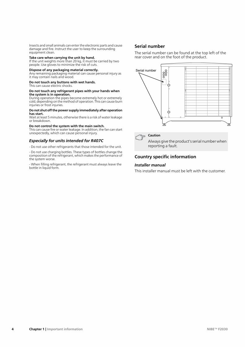
Serial numberThe serial number can be found at the top left of therear cover and on the foot of the product.
251
203
476 1074
257
40-60
50
176598
48049
5111145
140
1260
90
570
603
Serial number
Caution
Always give the product's serial number whenreporting a fault.
Country specific information
Installer manualThis installer manual must be left with the customer.
NIBE™ F2030Chapter 1 | Important information4
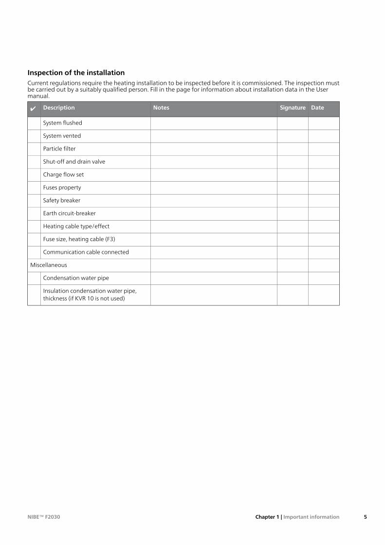
Inspection of the installationCurrent regulations require the heating installation to be inspected before it is commissioned. The inspection mustbe carried out by a suitably qualified person. Fill in the page for information about installation data in the Usermanual.
DateSignatureNotesDescription✔
System flushed
System vented
Particle filter
Shut-off and drain valve
Charge flow set
Fuses property
Safety breaker
Earth circuit-breaker
Heating cable type/effect
Fuse size, heating cable (F3)
Communication cable connected
Miscellaneous
Condensation water pipe
Insulation condensation water pipe,thickness (if KVR 10 is not used)
5Chapter 1 | Important informationNIBE™ F2030
Contact information
KNV Energietechnik GmbH, Gahberggasse 11, 4861 SchörflingAT
Tel: +43 (0)7662 8963-0 Fax: +43 (0)7662 8963-44 E-mail: [email protected] www.knv.atNIBE Wärmetechnik c/o ait Schweiz AG, Industriepark, CH-6246 AltishofenCH
Tel: (52) 647 00 30 Fax: (52) 647 00 31 E-mail: [email protected] www.nibe.chDruzstevni zavody Drazice s.r.o, Drazice 69, CZ - 294 71 Benatky nad JizerouCZ
Tel: +420 326 373 801 Fax: +420 326 373 803 E-mail: [email protected] www.nibe.czNIBE Systemtechnik GmbH, Am Reiherpfahl 3, 29223 CelleDE
Tel: 05141/7546-0 Fax: 05141/7546-99 E-mail: [email protected] www.nibe.deVølund Varmeteknik A/S, Member of the Nibe Group, Brogårdsvej 7, 6920 VidebækDK
Tel: 97 17 20 33 Fax: 97 17 29 33 E-mail: [email protected] www.volundvt.dkNIBE Energy Systems OY, Juurakkotie 3, 01510 VantaaFI
Puh: 09-274 697 0 Fax: 09-274 697 40 E-mail: [email protected] www.nibe.fiNIBE Energy Systems France Sarl, Zone industrielle RD 28, Rue du Pou du Ciel, 01600 ReyrieuxFR
Tel : 04 74 00 92 92 Fax : 04 74 00 42 00 E-mail: [email protected] www.nibe.frNIBE Energy Systems Ltd, 3C Broom Business Park, Bridge Way, Chesterfield S41 9QGGB
Tel: 0845 095 1200 Fax: 0845 095 1201 E-mail: [email protected] www.nibe.co.ukNIBE Energietechniek B.V., Postbus 634, NL 4900 AP OosterhoutNL
Tel: 0168 477722 Fax: 0168 476998 E-mail: [email protected] www.nibenl.nlABK AS, Brobekkveien 80, 0582 Oslo, Postadresse: Postboks 64 Vollebekk, 0516 OsloNO
Tel. sentralbord: +47 23 17 05 20 E-mail: [email protected] www.nibeenergysystems.noNIBE-BIAWAR Sp. z o. o. Aleja Jana Pawła II 57, 15-703 BIAŁYSTOKPL
Tel: 085 662 84 90 Fax: 085 662 84 14 E-mail: [email protected] www.biawar.com.pl© "EVAN" 17, per. Boynovskiy, Nizhny NovgorodRU
Tel./fax +7 831 419 57 06 E-mail: [email protected] www.nibe-evan.ruNIBE AB Sweden, Box 14, Hannabadsvägen 5, SE-285 21 MarkarydSE
Tel: +46-(0)433-73 000 Fax: +46-(0)433-73 190 E-mail: [email protected] www.nibe.se
For countries not mention in this list, please contact Nibe Sweden or check www.nibe.eu for more information.
NIBE™ F2030Chapter 1 | Important information6
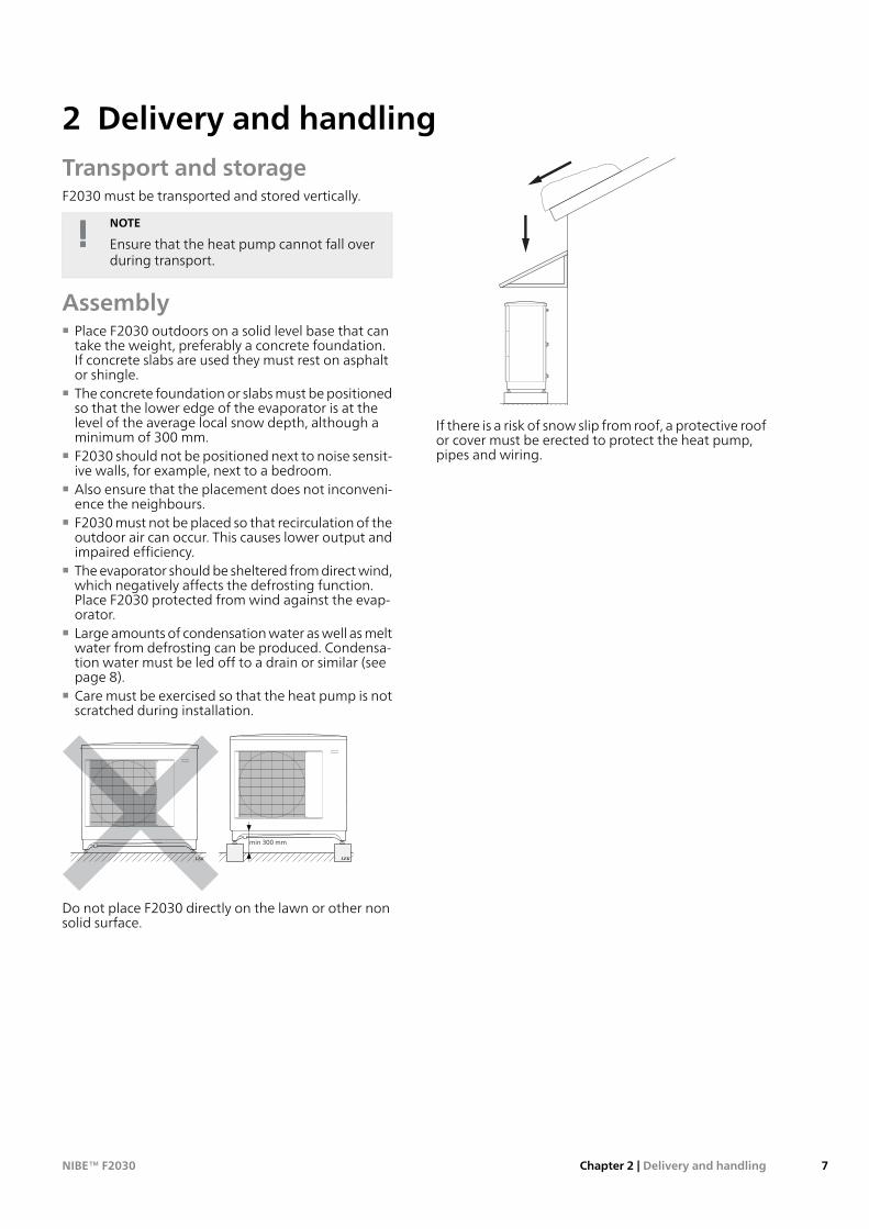
Transport and storageF2030 must be transported and stored vertically.
NOTE
Ensure that the heat pump cannot fall overduring transport.
Assembly■ Place F2030 outdoors on a solid level base that can
take the weight, preferably a concrete foundation.If concrete slabs are used they must rest on asphaltor shingle.
■ The concrete foundation or slabs must be positionedso that the lower edge of the evaporator is at thelevel of the average local snow depth, although aminimum of 300 mm.
■ F2030 should not be positioned next to noise sensit-ive walls, for example, next to a bedroom.
■ Also ensure that the placement does not inconveni-ence the neighbours.
■ F2030 must not be placed so that recirculation of theoutdoor air can occur. This causes lower output andimpaired efficiency.
■ The evaporator should be sheltered from direct wind,which negatively affects the defrosting function.Place F2030 protected from wind against the evap-orator.
■ Large amounts of condensation water as well as meltwater from defrosting can be produced. Condensa-tion water must be led off to a drain or similar (seepage 8).
■ Care must be exercised so that the heat pump is notscratched during installation.
LEK
LEK LEK
LEK
min 300 mm
Do not place F2030 directly on the lawn or other nonsolid surface.
If there is a risk of snow slip from roof, a protective roofor cover must be erected to protect the heat pump,pipes and wiring.
7Chapter 2 | Delivery and handlingNIBE™ F2030
2 Delivery and handling
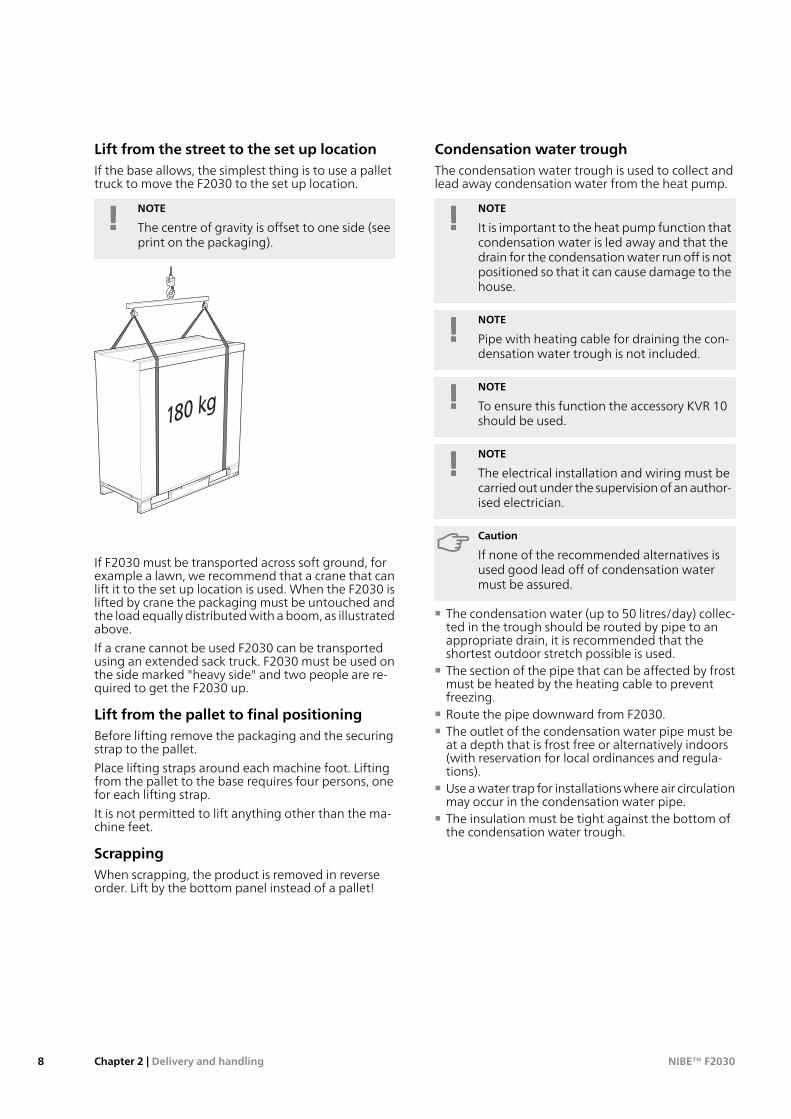
Lift from the street to the set up locationIf the base allows, the simplest thing is to use a pallettruck to move the F2030 to the set up location.
NOTE
The centre of gravity is offset to one side (seeprint on the packaging).
LEK
If F2030 must be transported across soft ground, forexample a lawn, we recommend that a crane that canlift it to the set up location is used. When the F2030 islifted by crane the packaging must be untouched andthe load equally distributed with a boom, as illustratedabove.
If a crane cannot be used F2030 can be transportedusing an extended sack truck. F2030 must be used onthe side marked "heavy side" and two people are re-quired to get the F2030 up.
Lift from the pallet to final positioningBefore lifting remove the packaging and the securingstrap to the pallet.
Place lifting straps around each machine foot. Liftingfrom the pallet to the base requires four persons, onefor each lifting strap.
It is not permitted to lift anything other than the ma-chine feet.
ScrappingWhen scrapping, the product is removed in reverseorder. Lift by the bottom panel instead of a pallet!
Condensation water troughThe condensation water trough is used to collect andlead away condensation water from the heat pump.
NOTE
It is important to the heat pump function thatcondensation water is led away and that thedrain for the condensation water run off is notpositioned so that it can cause damage to thehouse.
NOTE
Pipe with heating cable for draining the con-densation water trough is not included.
NOTE
To ensure this function the accessory KVR 10should be used.
NOTE
The electrical installation and wiring must becarried out under the supervision of an author-ised electrician.
Caution
If none of the recommended alternatives isused good lead off of condensation watermust be assured.
■ The condensation water (up to 50 litres/day) collec-ted in the trough should be routed by pipe to anappropriate drain, it is recommended that theshortest outdoor stretch possible is used.
■ The section of the pipe that can be affected by frostmust be heated by the heating cable to preventfreezing.
■ Route the pipe downward from F2030.■ The outlet of the condensation water pipe must be
at a depth that is frost free or alternatively indoors(with reservation for local ordinances and regula-tions).
■ Use a water trap for installations where air circulationmay occur in the condensation water pipe.
■ The insulation must be tight against the bottom ofthe condensation water trough.
NIBE™ F2030Chapter 2 | Delivery and handling8
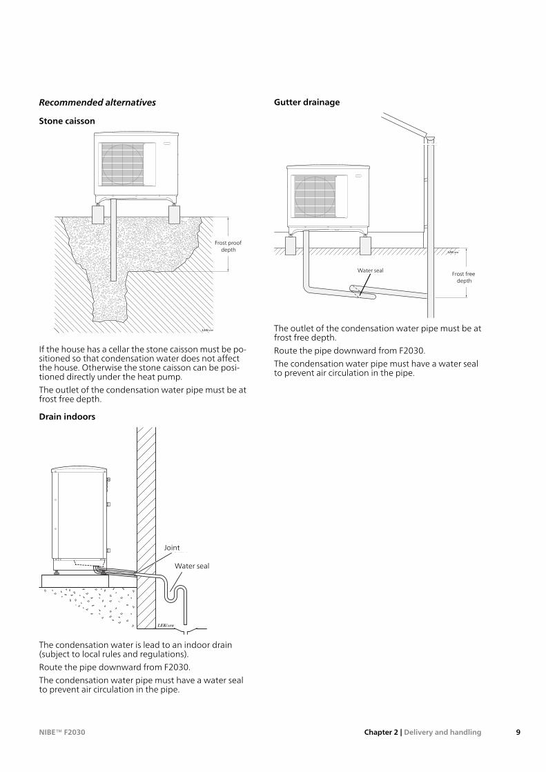
Recommended alternatives
Stone caisson
LEK/APH
Frostfritt djupFrost proof
depth
If the house has a cellar the stone caisson must be po-sitioned so that condensation water does not affectthe house. Otherwise the stone caisson can be posi-tioned directly under the heat pump.
The outlet of the condensation water pipe must be atfrost free depth.
Drain indoors
Skarv
Vattenlås
LEK/APH
Water seal
Joint
The condensation water is lead to an indoor drain(subject to local rules and regulations).
Route the pipe downward from F2030.
The condensation water pipe must have a water sealto prevent air circulation in the pipe.
Gutter drainage
LEK/APH
Frostfritt
djupFrost freedepth
Water seal
The outlet of the condensation water pipe must be atfrost free depth.
Route the pipe downward from F2030.
The condensation water pipe must have a water sealto prevent air circulation in the pipe.
9Chapter 2 | Delivery and handlingNIBE™ F2030
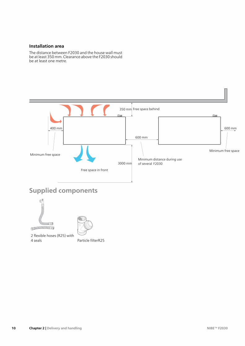
Installation areaThe distance between F2030 and the house wall mustbe at least 350 mm. Clearance above the F2030 shouldbe at least one metre.
400 m
m
Fritt utrymme bakom
Fritt utrymme framför
Min. avståndvid användningav flera F2030
600 mm
3000 m
m400 mm
Minimalt fritt utrymme
600mm
Minimalt fritt utrymme
Minimum free space
Free space behind
Free space in front
Minimum free space
Minimum distance during useof several F2030
350 mm
400 mm
600 mm
600 mm
3000 mm
Supplied components
LEK
Particle filterR252 flexible hoses (R25) with4 seals
NIBE™ F2030Chapter 2 | Delivery and handling10
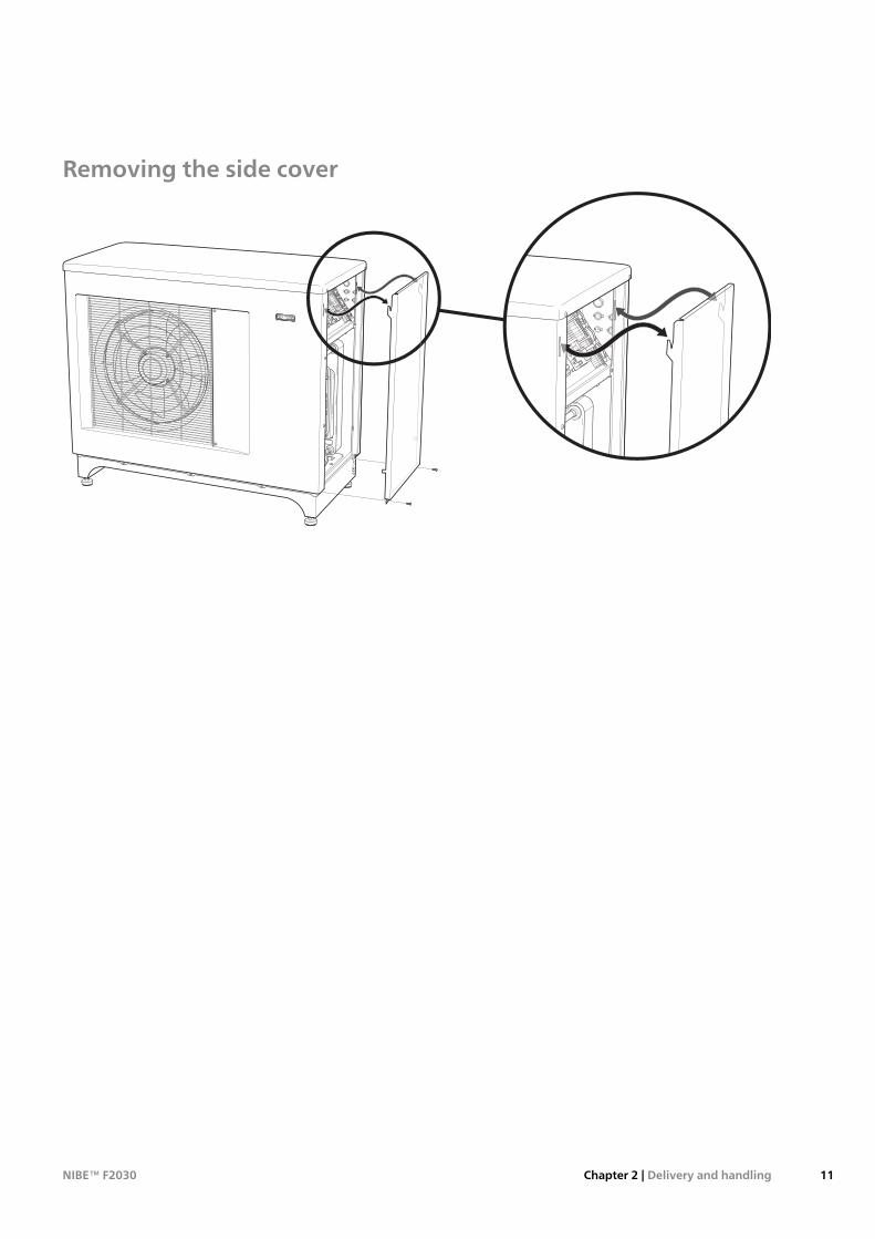
Removing the side cover
LE
K /
AP
H
11Chapter 2 | Delivery and handlingNIBE™ F2030
General
LEK
BT14 BP1
BT15
XL21
EP2
BT17
BP2
AA101
QN1
QN31
WM5
QN30
QN34
GQ10
HS1
AA100
UB1
XL40
EB13
GQ1
EB11
QN2XL20 EB10BP10
RM1
APH
BT16
EP1
UB1
XL40
PF3
XL2
BT3
XL1
BT12
BT28
PF1
PF3
NIBE™ F2030Chapter 3 | The heat pump design12
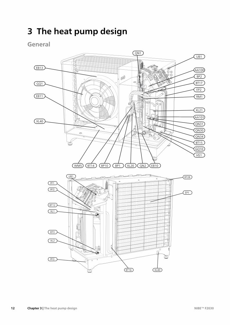
3 The heat pump design
Pipe connectionsConnection, heating medium out of F2030XL1Connection, heating medium in to F2030,XL2Service connection, high pressureXL20Service connection, low pressureXL21Connection, drain condensation water troughXL40
Sensors etc.High pressure pressostatBP1Low pressure pressostatBP2High pressure pressostatBP10Temperature sensor, returnBT3Temperature sensor, condenser supply lineBT12Temperature sensor, hot gasBT14Temperature sensor, fluid pipeBT15Temperature sensor, evaporatorBT16Temperature sensor, suction gasBT17Temperature sensor, ambientBT28
Electrical componentsJoint card, sensorAA100Joint cardAA101Compressor heaterEB10Condensation water trough heaterEB11Collar heaterEB13FanGQ1
Cooling componentsEvaporatorEP1CondenserEP2CompressorGQ10Drying filterHS1Expansion valveQN14-way valveQN2Solenoid valve, liquid injectionQN30Solenoid valve, subcoolingQN31Expansion valve, subcoolingQN34Non-return valveRM1
MiscellaneousType platePF1Serial numberPF3Cable gland, incoming supplyUB1Condensation water troughWM5
Designations in component locations according tostandard IEC 81346-1 and 81346-2.
13Chapter 3 | The heat pump designNIBE™ F2030
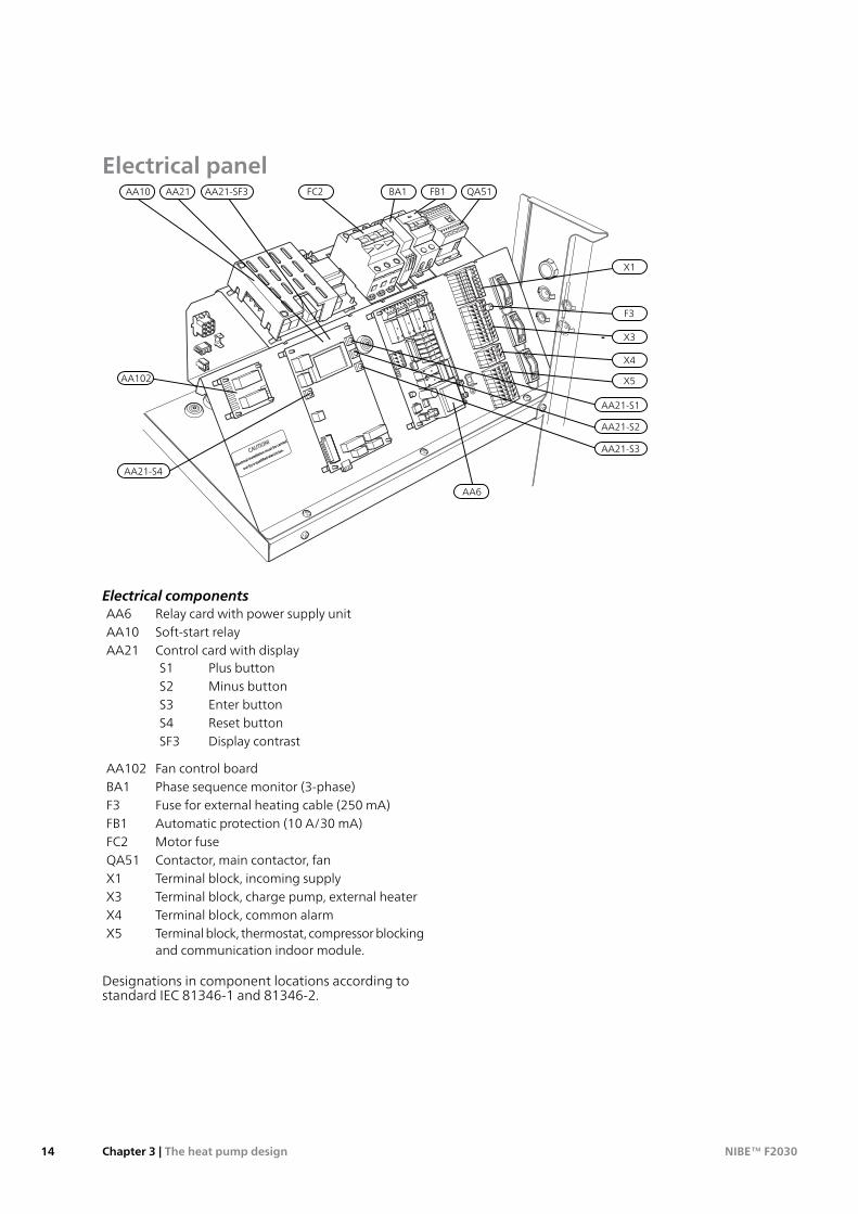
Electrical panel
F3
AA21-S4
AA21-S1
AA21-S2
AA21-S3
QA51FC2 BA1AA10 AA21-SF3
X3
X1
X4
X5
FB1
AA102
AA6
AA21
Electrical componentsRelay card with power supply unitAA6Soft-start relayAA10Control card with displayAA21
Plus buttonS1Minus buttonS2Enter buttonS3Reset buttonS4Display contrastSF3
Fan control boardAA102Phase sequence monitor (3-phase)BA1Fuse for external heating cable (250 mA)F3Automatic protection (10 A/30 mA)FB1Motor fuseFC2Contactor, main contactor, fanQA51Terminal block, incoming supplyX1Terminal block, charge pump, external heaterX3Terminal block, common alarmX4Terminal block, thermostat, compressor blockingand communication indoor module.
X5
Designations in component locations according tostandard IEC 81346-1 and 81346-2.
NIBE™ F2030Chapter 3 | The heat pump design14
GeneralPipe installation must be carried out in accordance withcurrent norms and directives.
F2030 can only operate up to a return temperature ofabout 55 °C and an outgoing temperature of about65 °C from the heat pump.
F2030 is not equipped with external shut off valves onthe water side; these must be installed to facilitate anyfuture servicing. The return temperature is limited bythe return line sensor.
Water volumesWhen docking with F2030 a minimum available systemvolume of at least 20 litres per kW output on the heatpump is recommended.
NOTE
The pipe work must be flushed before the heatpump is connected, so that any contaminantsdo not damage the components.
Pipe couplingheatingmediumcircuit■ F2030 can be connected to the heating system ac-
cording to one of the system solutions that can bedownloaded from the website www.nibe.eu.
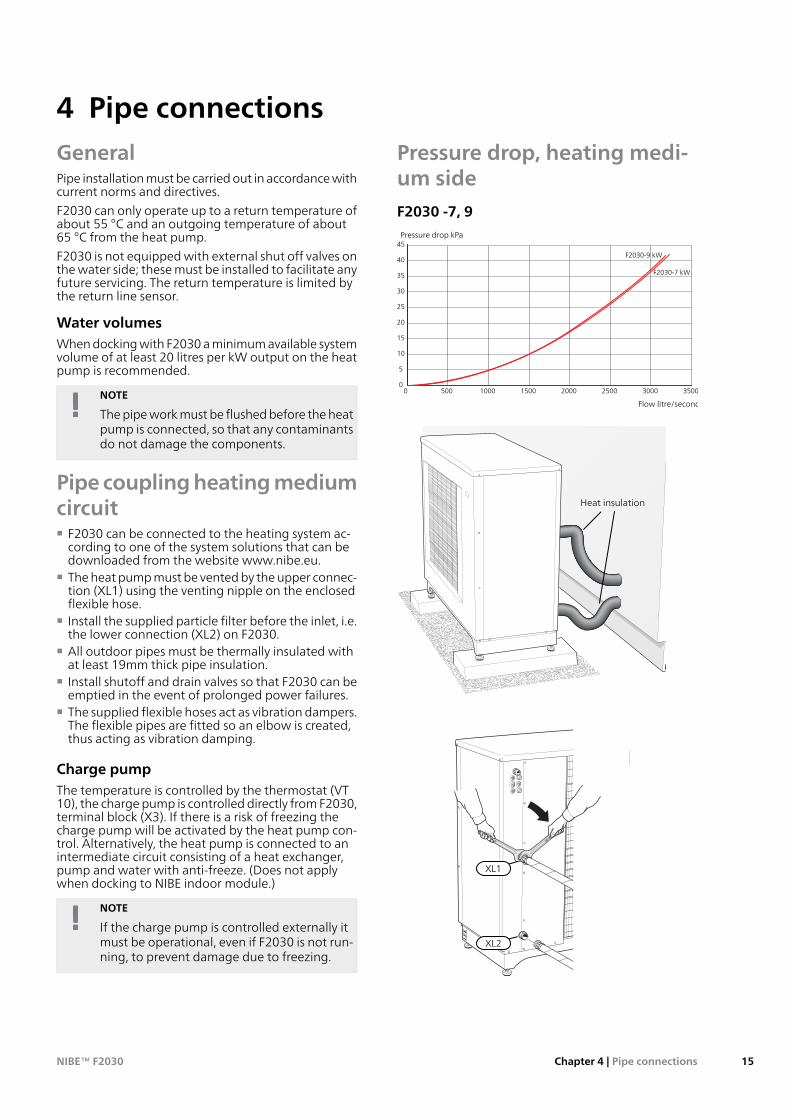
■ The heat pump must be vented by the upper connec-tion (XL1) using the venting nipple on the enclosedflexible hose.
■ Install the supplied particle filter before the inlet, i.e.the lower connection (XL2) on F2030.
■ All outdoor pipes must be thermally insulated withat least 19mm thick pipe insulation.
■ Install shutoff and drain valves so that F2030 can beemptied in the event of prolonged power failures.
■ The supplied flexible hoses act as vibration dampers.The flexible pipes are fitted so an elbow is created,thus acting as vibration damping.
Charge pumpThe temperature is controlled by the thermostat (VT10), the charge pump is controlled directly from F2030,terminal block (X3). If there is a risk of freezing thecharge pump will be activated by the heat pump con-trol. Alternatively, the heat pump is connected to anintermediate circuit consisting of a heat exchanger,pump and water with anti-freeze. (Does not applywhen docking to NIBE indoor module.)
NOTE
If the charge pump is controlled externally itmust be operational, even if F2030 is not run-ning, to prevent damage due to freezing.
Pressure drop, heating medi-um sideF2030 -7, 9
0
5
10
15
20
25
30
35
40
45
0 500 1000 1500 2000 2500 3000 3500
Tryckfall (kPa)
Flöde (liter/timme)
F2030 Tryckfall(värmebärarsida)
F2030-7 kW
F2030-9 kW
Pressure drop kPa
Flow litre/second
LEK
Heat insulation
LEK
XL2
XL1
15Chapter 4 | Pipe connectionsNIBE™ F2030
4 Pipe connections
General■ A heat pump must not be connected without the
permission of the electricity supplier and must beconnected under the supervision of a qualified elec-trician.
■ If a miniature circuit breaker is used this should havemotor characteristic "C" (compressor operation). ForMCB size see "Technical Specifications".
■ F2030 does not include an omnipolar circuit breakeron the incoming power supply. The heat pump’ssupply cable must be connected to a circuit-breakerwith at least a 3 mm breaking gap. When the build-ing is equipped with an earth-fault breaker the heatpump should be equipped with a separate one. In-coming supply must be 400 V 3NAC 50Hz via distri-bution boards with fuses.
■ If an insulation test is to be carried out in the building,disconnect the heat pump.
■ Connect control signal cable for thermostat to ter-minal (X5). Cable type: unscreened LiYY, screenedLiYCY. Cable area, at least 0.22with cable lengths lessthan 50m.
■ Alternatively the relevant screened signal cable isconnected from terminal block (X5) to the indoormodule from NIBE.
■ The routing of cables for heavy current and signalsshould be made out through the cable glands on theheat pump's right-hand side, seen from the front.
■ Charge pump for F2030 can be connected to separ-ate supply or to terminal block (X3).NOTE! If F2030 is not powered and the charge pumpis connected to the terminal block (X3) there is a riskof freezing
■ A common alarm can be connected to terminal (X4).
NOTE
Electrical installation and service must be car-ried out under the supervision of a qualifiedelectrician. Electrical installation and wiringmust be carried out in accordance with thestipulations in force.
NOTE
The live external control must be taken intoconsideration when connecting.
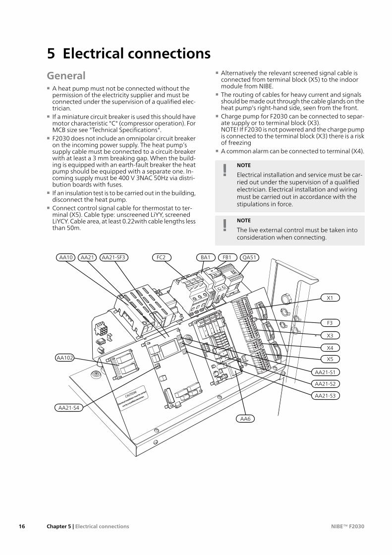
F3
AA21-S4
AA21-S1
AA21-S2
AA21-S3
QA51FC2 BA1AA10 AA21-SF3
X3
X1
X4
X5
FB1
AA102
AA6
AA21
NIBE™ F2030Chapter 5 | Electrical connections16
5 Electrical connections
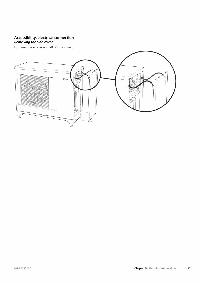
Accessibility, electrical connectionRemoving the side cover
Unscrew the screws and lift off the cover.
LE
K /
AP
H
17Chapter 5 | Electrical connectionsNIBE™ F2030
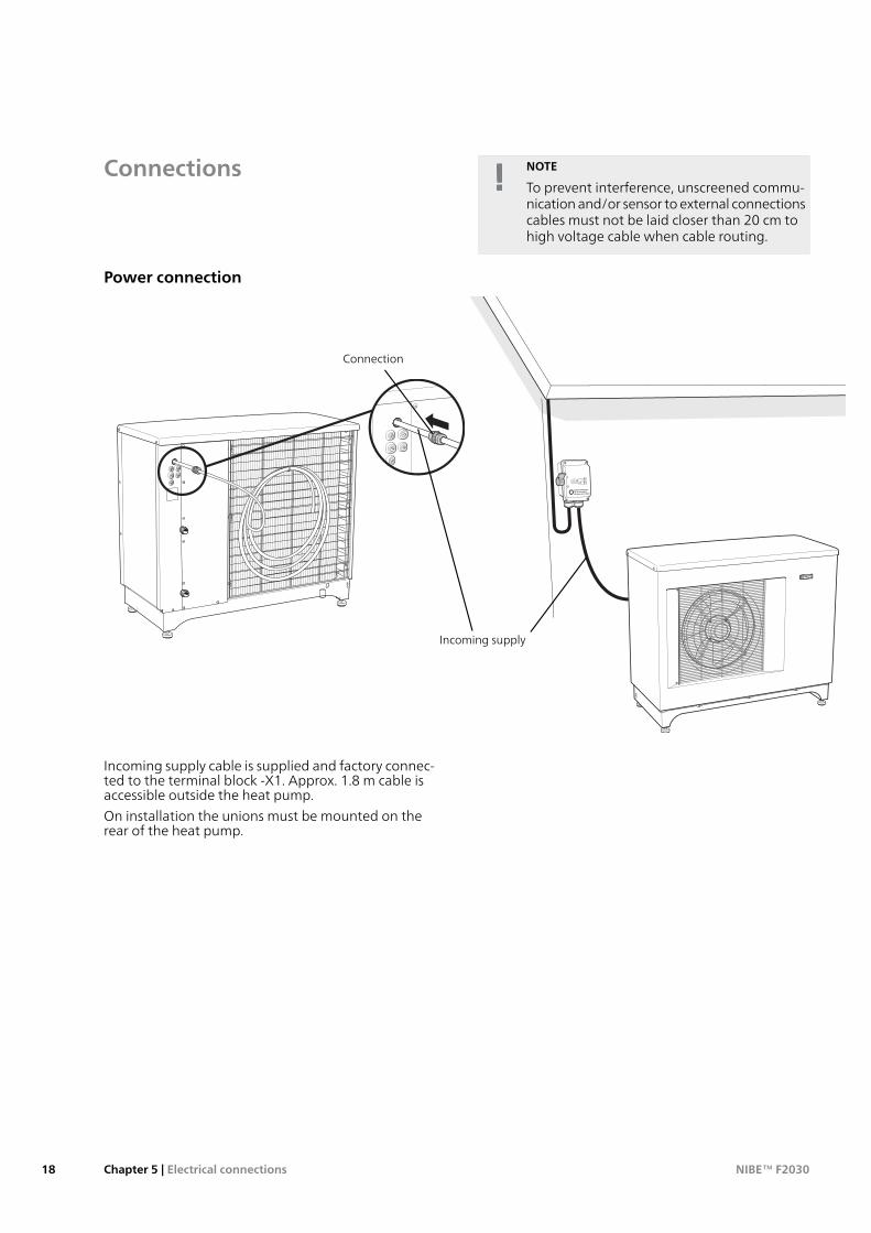
Connections NOTE
To prevent interference, unscreened commu-nication and/or sensor to external connectionscables must not be laid closer than 20 cm tohigh voltage cable when cable routing.
Power connection
LEK
APH
Incoming supply
Connection
Incoming supply cable is supplied and factory connec-ted to the terminal block -X1. Approx. 1.8 m cable isaccessible outside the heat pump.
On installation the unions must be mounted on therear of the heat pump.
NIBE™ F2030Chapter 5 | Electrical connections18

Connecting external control voltage
NOTE
Mark up any junction boxes with warnings forexternal voltage.
When connecting external control voltage with separ-ate earth-fault breaker, remove the straps betweenterminal blocks X1:L1 and X1:L and between terminalblocks X1:N andX1:0 (see image).
Control voltage (230V 50 Hz) is connected to terminalblocks X1:L and X1:0 (as illustrated).
L1
-X1
L2
L3
N
L
0
L
0
F2030 Externt
X1
F2030 External
At connection of external control voltage you mustconnect a switch (for tariff control) to connection X5:5and X5:6 (compressor blocking) to prevent MP alarm.
86
75
42
31
X5
ExternalF2030
Compressor blocking
Charge pumpTo let F2030 control the charge pump (GP12), connectit to the terminal block X3:1(PE), 3(L) and 4(N). Pumpactivity is dependent on the status of F2030, heat-ing/hot water requirement and the ambient temperat-ure. Pump exercising is handled by F2030.
With potential free connection of the circulation pumpyou replace the bracket with separate voltage supplyfor X3:2(L).
Anti-freeze function
At temperatures below +2 °C the charger pump runsperiodically, to prevent the water from freezing in thecharge circuit. The function also protects against excesstemperatures in the charge circuit. This function applieson the condition that F2030 is powered.
NOTE
There is a risk of freezing when the chargepump is connected to the terminal block - X3and F2030 is not powered.
56
74
23
1
N
L
PE
ExternalF2030
X3 GP12
19Chapter 5 | Electrical connectionsNIBE™ F2030
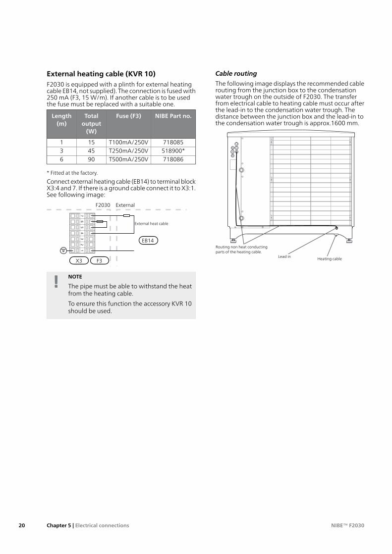
External heating cable (KVR 10)F2030 is equipped with a plinth for external heatingcable EB14, not supplied). The connection is fused with250 mA (F3, 15 W/m). If another cable is to be usedthe fuse must be replaced with a suitable one.
NIBE Part no.Fuse (F3)Totaloutput(W)
Length(m)
718085T100mA/250V151518900*T250mA/250V453718086T500mA/250V906
* Fitted at the factory.
Connect external heating cable (EB14) to terminal blockX3:4 and 7. If there is a ground cable connect it to X3:1.See following image:
56
74
23
1
ExternalF2030
X3
EB14
External heat cable
F3
NOTE
The pipe must be able to withstand the heatfrom the heating cable.
To ensure this function the accessory KVR 10should be used.
Cable routing
The following image displays the recommended cablerouting from the junction box to the condensationwater trough on the outside of F2030. The transferfrom electrical cable to heating cable must occur afterthe lead-in to the condensation water trough. Thedistance between the junction box and the lead-in tothe condensation water trough is approx.1600 mm.
Routing non heat conductingparts of the heating cable.
Lead in Heating cable
NIBE™ F2030Chapter 5 | Electrical connections20
Optional connectionsNOTE
The following pages about thermostats, addi-tional heat, common alarms and downtime,do not apply when F2030 is controlled by aNIBE indoor module.
Thermostat controlYou can use a basic thermostat or a closing potential-free contact to switch the compressor on and off. Thisthermostat should be of the breaking type (NC) whenthe set temperature has been reached. The contactorshould be potential free.
Connect the thermostat to terminal block X5:7 and 8as illustrated below.
86
75
42
31
X5
ExternalF2030
Thermostat
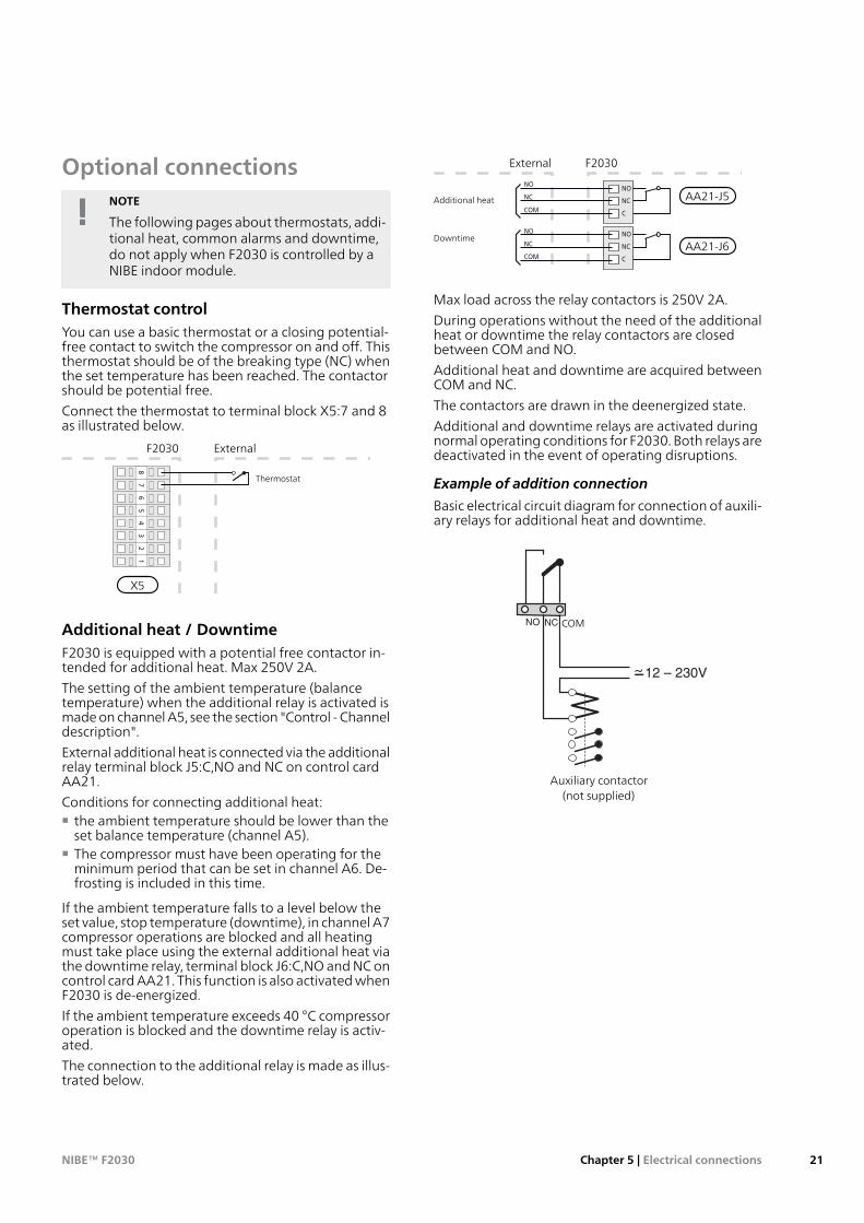
Additional heat / DowntimeF2030 is equipped with a potential free contactor in-tended for additional heat. Max 250V 2A.
The setting of the ambient temperature (balancetemperature) when the additional relay is activated ismade on channel A5, see the section "Control - Channeldescription".
External additional heat is connected via the additionalrelay terminal block J5:C,NO and NC on control cardAA21.
Conditions for connecting additional heat:■ the ambient temperature should be lower than the
set balance temperature (channel A5).■ The compressor must have been operating for the
minimum period that can be set in channel A6. De-frosting is included in this time.
If the ambient temperature falls to a level below theset value, stop temperature (downtime), in channel A7compressor operations are blocked and all heatingmust take place using the external additional heat viathe downtime relay, terminal block J6:C,NO and NC oncontrol card AA21. This function is also activated whenF2030 is de-energized.
If the ambient temperature exceeds 40 °C compressoroperation is blocked and the downtime relay is activ-ated.
The connection to the additional relay is made as illus-trated below.
NO
NC
C
NO
NC
C
Tillsatsvärme
Stillestånd
NO
NC
COM
NO
NC
COM
External F2030
AA21-J5Additional heat
DowntimeAA21-J6
Max load across the relay contactors is 250V 2A.
During operations without the need of the additionalheat or downtime the relay contactors are closedbetween COM and NO.
Additional heat and downtime are acquired betweenCOM and NC.
The contactors are drawn in the deenergized state.
Additional and downtime relays are activated duringnormal operating conditions for F2030. Both relays aredeactivated in the event of operating disruptions.
Example of addition connection
Basic electrical circuit diagram for connection of auxili-ary relays for additional heat and downtime.
LP HP
34
NO O/CNC
Hjälpkontaktor
(ingår ej vid leverans)
12 – 230V
158890864133
89
93
34
91
Auxiliary contactor(not supplied)
COM
21Chapter 5 | Electrical connectionsNIBE™ F2030
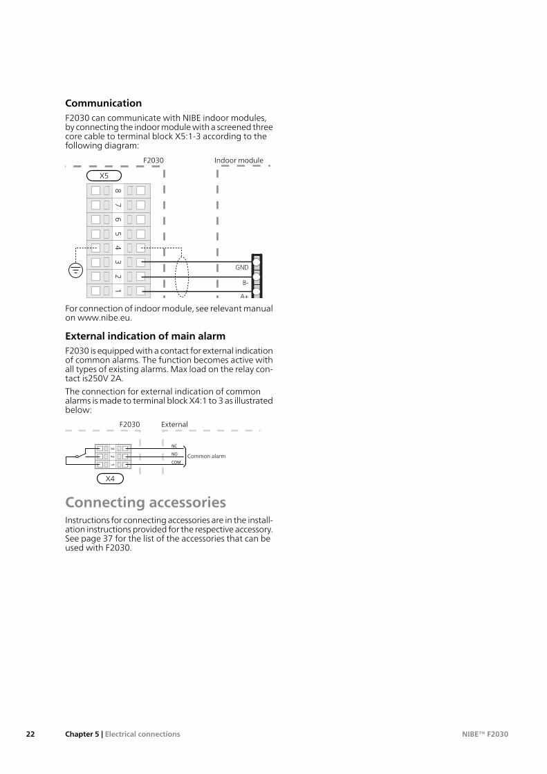
CommunicationF2030 can communicate with NIBE indoor modules,by connecting the indoor module with a screened threecore cable to terminal block X5:1-3 according to thefollowing diagram:
86
75
42
31
GND
B-
A+
F2030 Innemodul
-X5
F2030 Indoor module
X5
For connection of indoor module, see relevant manualon www.nibe.eu.
External indication of main alarmF2030 is equipped with a contact for external indicationof common alarms. The function becomes active withall types of existing alarms. Max load on the relay con-tact is250V 2A.
The connection for external indication of commonalarms is made to terminal block X4:1 to 3 as illustratedbelow:
32
1
Summalarm
NC
NO
COM
ExternalF2030
X4
Common alarm
Connecting accessoriesInstructions for connecting accessories are in the install-ation instructions provided for the respective accessory.See page 37 for the list of the accessories that can beused with F2030.
NIBE™ F2030Chapter 5 | Electrical connections22
Preparations■ Ensure that the heat pump cannot be damaged
during transport.■ Before commissioning, check that the heating circuit
is filled and well vented.■ Check the pipe system for leaks.
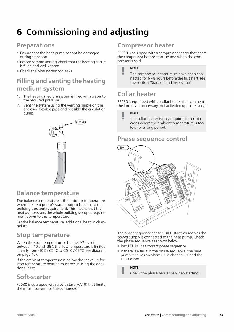
Filling andventing theheatingmedium system1. The heating medium system is filled with water to
the required pressure.2. Vent the system using the venting nipple on the
enclosed flexible pipe and possibly the circulationpump.
LEK
QM20
Balance temperatureThe balance temperature is the outdoor temperaturewhen the heat pump’s stated output is equal to thebuilding’s output requirement. This means that theheat pump covers the whole building’s output require-ment down to this temperature.
Set the balance temperature, additional heat, in chan-nel A5.
Stop temperatureWhen the stop temperature (channel A7) is setbetween -10 and -25 C the flow temperature is limitedlinearly from -10 C / 65 °C to -25 °C / 63 °C (see diagramon page 42).
If the ambient temperature is below the set value forstop temperature heating must occur using the addi-tional heat.
Soft-starterF2030 is equipped with a soft-start (AA10) that limitsthe inrush current for the compressor.
Compressor heaterF2030 is equipped with a compressor heater that heatsthe compressor before start-up and when the com-pressor is cold.
NOTE
The compressor heater must have been con-nected for 6 – 8 hours before the first start, seethe section "Start-up and inspection".
Collar heaterF2030 is equipped with a collar heater that can heatthe fan collar if necessary (not activated upon delivery).
NOTE
The collar heater is only required in certaincases where the ambient temperature is toolow for a long period.
Phase sequence controlBA1
The phase sequence sensor (BA1) starts as soon as thepower supply is connected to the heat pump. Checkthe phase sequence as shown below.■ Red LED is lit at correct phase sequence■ If there is a fault in the phase sequence, the heat
pump receives an alarm 07 in channel S1 and theLED flashes.
NOTE
Check the phase sequence when starting!
23Chapter 6 | Commissioning and adjustingNIBE™ F2030
6 Commissioning and adjusting
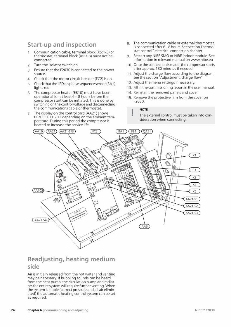
Start-up and inspection1. Communication cable, terminal block (X5:1-3) or
thermostat, terminal block (X5:7-8) must not beconnected.
2. Turn the isolator switch on.3. Ensure that the F2030 is connected to the power
source.4. Check that the motor circuit-breaker (FC2) is on.5. Check that the LED on phase sequence sensor (BA1)
lights red.6. The compressor heater (EB10) must have been
operational for at least 6 – 8 hours before thecompressor start can be initiated. This is done byswitching on the control voltage and disconnectingthe communications cable or thermostat.
7. The display on the control card (AA21) showsC0/CC F0 H1/H3 depending on the ambient tem-perature. During this period the compressor isheated to increase the service life.
8. The communication cable or external thermostatis connected after 6 – 8 hours. See section Thermo-stat control” electrical connection chapter.
9. Restart any NIBE SMO or NIBE indoor module. Seeinformation in relevant manual on www.nibe.eu
10. Once the connection is made, the compressor startsafter approx. 180 minutes if needed.
11. Adjust the charge flow according to the diagram,see the section "Adjustment, charge flow"
12. Adjust the menu settings if necessary.13. Fill in the commissioning report in the user manual.14. Reinstall the removed panels and cover.15. Remove the protective film from the cover on
F2030.
NOTE
The external control must be taken into con-sideration when connecting.
F3
AA21-S4
AA21-S1
AA21-S2
AA21-S3
QA51FC2 BA1AA10 AA21-SF3
X3
X1
X4
X5
FB1
AA102
AA6
AA21
Readjusting, heating mediumsideAir is initially released from the hot water and ventingmay be necessary. If bubbling sounds can be heardfrom the heat pump, the circulation pump and radiat-ors the entire system will require further venting. Whenthe system is stable (correct pressure and all air elimin-ated) the automatic heating control system can be setas required.
NIBE™ F2030Chapter 6 | Commissioning and adjusting24
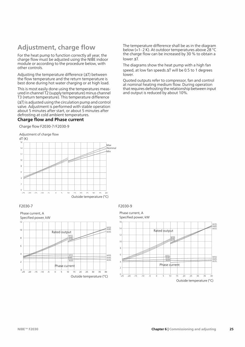
Adjustment, charge flowFor the heat pump to function correctly all year, thecharge flow must be adjusted using the NIBE indoormodule or according to the procedure below, withother controls.
Adjusting the temperature difference (ΔT) betweenthe flow temperature and the return temperature isbest done during hot water charging or at high load.
This is most easily done using the temperatures meas-ured in channel T2 (supply temperature) minus channelT3 (return temperature). This temperature difference(ΔT) is adjusted using the circulation pump and controlvalve. Adjustment is performed with stable operationabout 5 minutes after start, or about 5 minutes afterdefrosting at cold ambient temperatures.
The temperature difference shall be as in the diagrambelow (+1- 2 K). At outdoor temperatures above 28 °Cthe charge flow can be increased by 30 % to obtain alower ΔT.
The diagrams show the heat pump with a high fanspeed, at low fan speeds ΔT will be 0.5 to 1 degreeslower.
Quoted outputs refer to compressor, fan and controlat nominal heating medium flow. During operationthat requires defrosting the relationship between inputand output is reduced by about 10%.
Charge flow and Phase currentCharge flow F2030-7/F2030-9
F2030 TeTT mperature Different Between WaWW ter Supplying and Return EN255
0
2
4
6
8
10
12
14
16 dT (K) T
-25 -20 -15 -10 -5 0 5 10 15 20 25 30 35 40
Out-door air temperature (°C)
Adjustment of charge flowdT (K)
Outside temperature (°C)
Max
MinNominal
F2030-9F2030-7
F2030-9 kW Heat Capacity and Currents EN255
W35
W35
W45
W45
W55
W55
W35W45W55
W35W45W55
-25 -20 -15 -10 -5 0 5 10 15 20 25 30 35 40
Out door air temperature (°C)
0
2
4
6
8
10
12
14
16 Heat capacity (kW) & Currents (A)
Phase current, ASpecified power, kW
Outside temperature (°C)
Rated output
Phase current
F2030-7 kW Heat capacity and Currents EN255
W55W45W35
W55W45W35
W55W45
W35
W55W45W35
-25 -20 -15 -10 -5 0 5 10 15 20 25 30 35 40
Out-door Temperature (°C)
0
2
4
6
8
10
12
Heat capacity (kW) and Currents /A)
Phase current, ASpecified power, kW
Outside temperature (°C)
Phase current
Rated output
25Chapter 6 | Commissioning and adjustingNIBE™ F2030
GeneralF2030 is equipped with an internal electronic controlthat handles those functions that are necessary foroperation of the heat pump, for example defrosting,stop at max/min temperature, connection of thecompressor heater as well as enabling the heater forthe condensation watering trough and monitoring ofpressure switches.
The temperatures, number of starts and the operatingtime can also be read.
The integrated controller is set during installation andcan be used during a service.
Under normal operating conditions the home ownerdoes not need to have access to the controller.
F2030 has an integrated return line sensor that limitsthe return temperature.
F2030 can also be switched on/off via signals fromother control equipment or a thermostat. If F2030 iscontrolled from a NIBE indoor module (accessory) thecontrol is described in the instructions supplied.
F2030 communicates with NIBE SMO or the indoormodule which means that settings and measurementvalues from F2030 can be adjusted and read off in theindoor module.
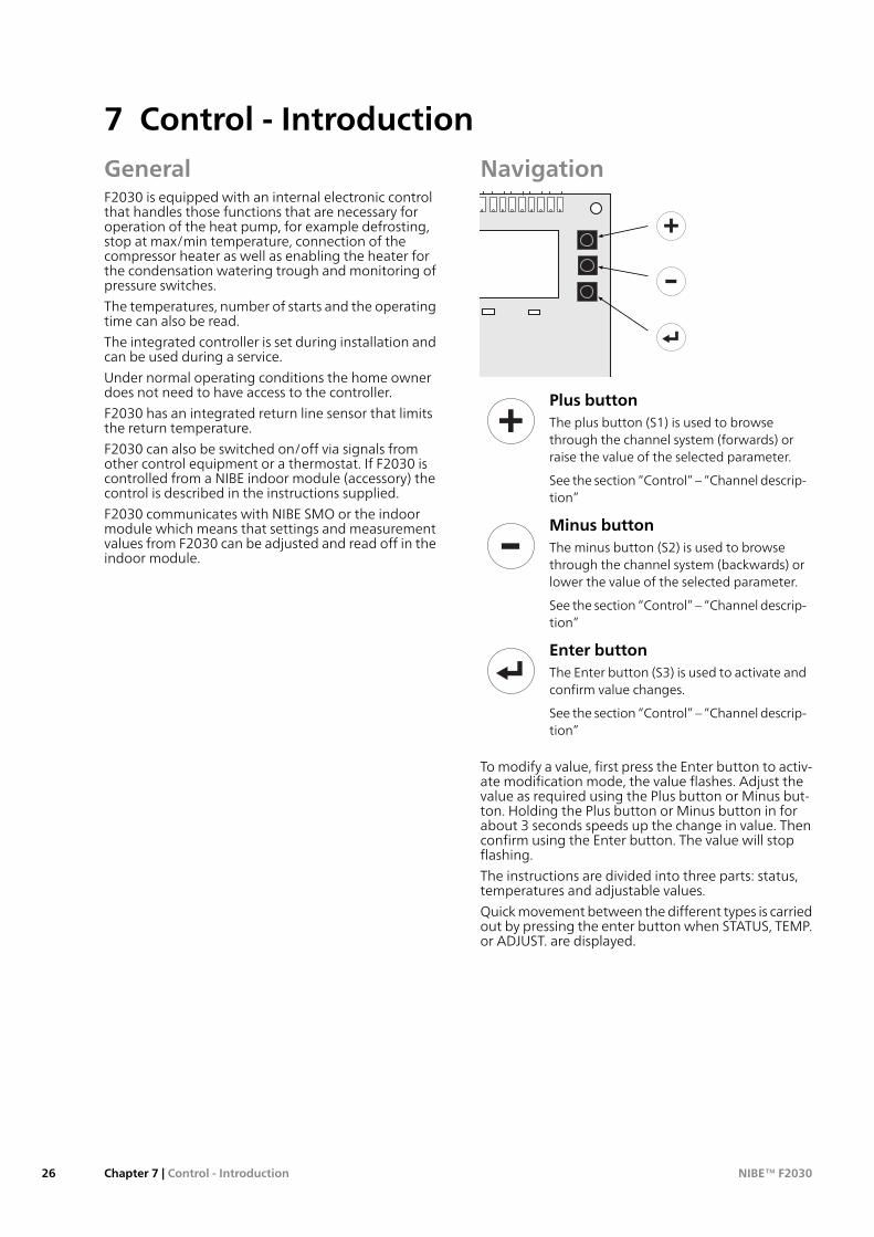
Navigation
LP HP
34
NO O/CNC
Hjälpkontaktor
(ingår ej vid leverans)
12 – 230V
158890864133
89
93
34
91
Plus buttonThe plus button (S1) is used to browsethrough the channel system (forwards) orraise the value of the selected parameter.
See the section “Control” – “Channel descrip-tion”
Minus buttonThe minus button (S2) is used to browsethrough the channel system (backwards) orlower the value of the selected parameter.
See the section “Control” – “Channel descrip-tion”
Enter buttonThe Enter button (S3) is used to activate andconfirm value changes.
See the section “Control” – “Channel descrip-tion”
To modify a value, first press the Enter button to activ-ate modification mode, the value flashes. Adjust thevalue as required using the Plus button or Minus but-ton. Holding the Plus button or Minus button in forabout 3 seconds speeds up the change in value. Thenconfirm using the Enter button. The value will stopflashing.
The instructions are divided into three parts: status,temperatures and adjustable values.
Quick movement between the different types is carriedout by pressing the enter button when STATUS, TEMP.or ADJUST. are displayed.
NIBE™ F2030Chapter 7 | Control - Introduction26
7 Control - Introduction
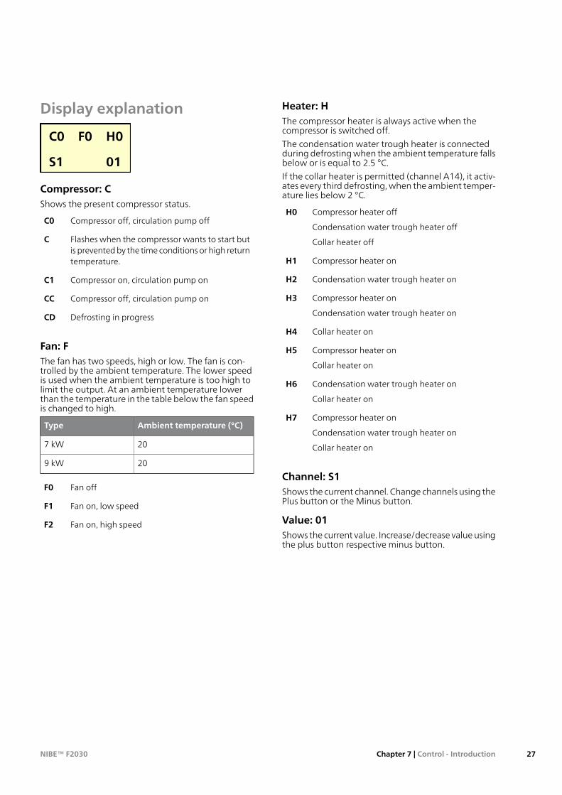
Display explanation
C0 F0 H0
S1 01
Compressor: CShows the present compressor status.
Compressor off, circulation pump offC0
Flashes when the compressor wants to start butis prevented by the time conditions or high returntemperature.
C
Compressor on, circulation pump onC1
Compressor off, circulation pump onCC
Defrosting in progressCD
Fan: FThe fan has two speeds, high or low. The fan is con-trolled by the ambient temperature. The lower speedis used when the ambient temperature is too high tolimit the output. At an ambient temperature lowerthan the temperature in the table below the fan speedis changed to high.
Ambient temperature (°C)Type
207 kW
209 kW
Fan offF0
Fan on, low speedF1
Fan on, high speedF2
Heater: HThe compressor heater is always active when thecompressor is switched off.
The condensation water trough heater is connectedduring defrosting when the ambient temperature fallsbelow or is equal to 2.5 °C.
If the collar heater is permitted (channel A14), it activ-ates every third defrosting, when the ambient temper-ature lies below 2 °C.
Compressor heater off
Condensation water trough heater off
Collar heater off
H0
Compressor heater onH1
Condensation water trough heater onH2
Compressor heater on
Condensation water trough heater on
H3
Collar heater onH4
Compressor heater on
Collar heater on
H5
Condensation water trough heater on
Collar heater on
H6
Compressor heater on
Condensation water trough heater on
Collar heater on
H7
Channel: S1Shows the current channel. Change channels using thePlus button or the Minus button.
Value: 01Shows the current value. Increase/decrease value usingthe plus button respective minus button.
27Chapter 7 | Control - IntroductionNIBE™ F2030
Control conditionsControl conditions, cold outdoor air■ When the ambient air temperature (channel T1)
drops below the set temperature in channel A7 theheat pump stops and indicates 03 in channel S1. Boththe additional relay and the downtime relay are thenactivated at the same time.
■ If the ambient temperature sensor registers a temper-ature that is at least 2.1 °C higher than the set tem-perature in channel A7, a time counter starts.
■ When the time counter has reached 45 minutes, boththe additional relay and downtime relay deactivateto obtain a more comfortable temperature for thecompressor to start at.
■ When a further 15 minutes have passed, the com-pressor is permitted to start and the additional relayactivates a few seconds later. However, the downtimerelay is deactivated.
■ If the ambient temperature at any point during thetotal 60 minutes falls below channel A7 + 2.1 °C thecounter is reset. It does not start counting again un-less the temperature is sufficiently high once again.
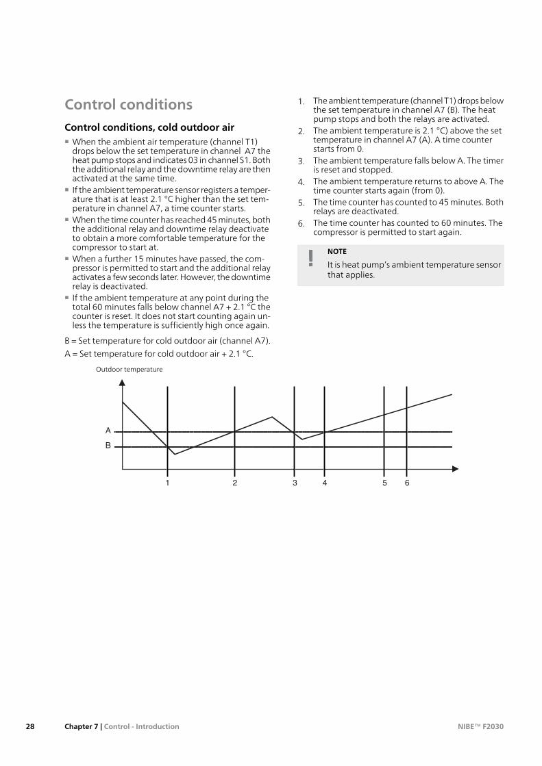
B = Set temperature for cold outdoor air (channel A7).
A = Set temperature for cold outdoor air + 2.1 °C.
1. The ambient temperature (channel T1) drops belowthe set temperature in channel A7 (B). The heatpump stops and both the relays are activated.
2. The ambient temperature is 2.1 °C) above the settemperature in channel A7 (A). A time counterstarts from 0.
3. The ambient temperature falls below A. The timeris reset and stopped.
4. The ambient temperature returns to above A. Thetime counter starts again (from 0).
5. The time counter has counted to 45 minutes. Bothrelays are deactivated.
6. The time counter has counted to 60 minutes. Thecompressor is permitted to start again.
NOTE
It is heat pump’s ambient temperature sensorthat applies.
utelufttemp.
A
B
1 2 3 4 5 6
UtelufttemperaturOutdoor temperature
NIBE™ F2030Chapter 7 | Control - Introduction28
Control conditions defrostingA16:1 (factorysetting)■ Defrosting occurs actively (with compressor on and
fan off) or passively (with compressor off and fan on).■ A time counter counts up every minute if the com-
pressor is running and the temperature of the evap-orator sensor (channel T7) falls below the setting inchannel A9
■ Channel S9 shows time to defrost in minutes. Whenthis value is 0 minutes defrosting starts.
■ If the collar heater is activated in channel A14, theambient temperature is less than or equivalent to2 °C and the compressor is running the collar heaterstarts at every third defrosting. The collar heaterprevents the build up of ice on the fan collar.
■ If "deicing fan" is activated in channel A15, depend-ing on the evaporation temperature and if the collarheater is not running, deicing fan starts during de-frost. The deicing fan prevents the build up of ice onthe fan blades and the front fan grille.
■ If the evaporator is too cold a "safety defrost" starts.This defrost can be started earlier than when thenormal defrost would start. If 10 safety defrosts in arow occur alarm 19 (channel S1) is activated whichis a permanent alarm.
■ If defrosting is necessary, passive defrosting startswhen T1 ≥ 4 °C and the compressor has stopped be-cause the heating requirement has been met.
Active defrosting at T1 < 4 °C:1. The four way valve shifts to defrosting.2. The fan stops and the compressor continues to run.3. When defrosting is complete the four way valve
shifts back to heating mode and after 30 secondsthe fan starts.
4. The ambient temperature sensor is locked and thehigh return temperature alarm is blocked for twominutes after defrosting.
Passive defrosting T1 ≥ 4 °C:1. The compressor stops.2. The four way valve does not shift.3. Fan runs at high speed.4. When passive defrosting is complete, the com-
pressor starts.5. The ambient temperature sensor is locked and the
high return temperature alarm is blocked for twominutes after defrosting.
Passive defrosting ends when time in S9 = A8.
There are five possible reasons for an active de-frosting to end:1. The temperature of the evaporator sensor has
reached the set temperature in channel A10 (nor-mal stop).
2. When defrosting has gone on for longer than 15minutes. This may be due to too little energy in theheat source, too strong wind effect on the evapor-ator and/or that the sensor on the evaporator isnot correct and therefore displays too low temper-ature (at cold outdoor air).
3. When the temperature on the return line sensorchannel T3 falls below 10 °C.
4. The high-pressure switch deploys during defrost-ing. This is indicated as alarm 10 in channel S1 andthe compressor is stopped. After two minutes thecompressor starts again (if the pressure has fallen),otherwise there is a constant high pressure alarm(alarm 06).
5. The temperature on the supply line sensor channelT2 falls below 4 .
Control conditions defrosting A16:0■ A time counter counts up every minute if the com-
pressor is running and the temperature of the evap-orator sensor (channel T7) falls below the setting inchannel A9
■ Defrosting starts if the timer S9 has counted downor the temperature conditions for defrosting are met.
■ If the collar heater is activated in channel A14, theambient temperature is less than or equivalent to2 °C and the compressor is running the collar heaterstarts at every third defrosting. The collar heaterprevents the build up of ice on the fan collar.
■ If "deicing fan" is activated in channel A15, depend-ing on the evaporation temperature and if the collarheater is not running, deicing fan starts during de-frost. The deicing fan prevents the build up of ice onthe fan blades and the front fan grille.
■ If the evaporator is too cold a "safety defrost" starts.This defrost can be started earlier than when thenormal defrost would start. If 10 safety defrosts in arow occur alarm 19 (channel S1) is activated whichis a permanent alarm.
Defrosting occurs as follows:1. The four way valve shifts to defrosting2. The fan stops and the compressor continues to run.3. When defrosting is complete the four way valve
shifts back to heating mode and after 30 secondsthe fan starts.
4. The ambient temperature sensor is locked and thehigh return temperature alarm is blocked for twominutes after defrosting.
There are five possible reasons for defrosting tofinish:1. The temperature of the evaporator sensor has
reached the set temperature in channel A10 (nor-mal stop).
2. When defrosting has gone on for longer than 15minutes. This may be due to too little energy in theheat source, too strong wind effect on the evapor-ator and/or that the sensor on the evaporator isnot correct and therefore displays too low temper-ature (at cold outdoor air).
3. The temperature on the return sensor falls below10 °C.
4. The high-pressure switch deploys during defrost-ing. This is indicated as alarm 10 in channel S1 andthe compressor is stopped. After two minutes thecompressor starts again (if the pressure has fallen),otherwise there is a constant high pressure alarm(alarm 06).
29Chapter 7 | Control - IntroductionNIBE™ F2030

5. The temperature on the flow temperature sensorfalls below 4 °C.
NIBE™ F2030Chapter 7 | Control - Introduction30
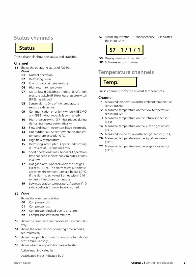
Status channels
Status
These channels show the status and statistics.
ChannelShows the operating status of F2030.S1Value
Normal operation.01Defrosting is run.02Cold outdoor air temperature.03High return temperature.04Motor fuse (FC2), phase monitor (BA1), highpressure switch (BP10) or low pressure switch(BP2) has tripped.
07
Sensor alarm. One of the temperaturesensors is defective.
08
Communication error (only when NIBE SMOand NIBE indoor module is connected).
09
High pressure switch (BP1) has tripped duringdefrosting (resets automatically)
10
Flow and return line sensors fitted incorrectly.12Hot outdoor air. Appears when the ambienttemperature exceeds 40 °C.
13
High flow temperature.14Defrosting interrupted. Appears if defrostingis unsuccessful 3 times in a row.
15
Short operations times. Appears if operationtime has been shorter than 2 minutes 3 timesin a row.
16
Hot gas alarm. Appears when the hot gasexceeds 135 °C. The alarm resets automatic-
17
ally when the temperature falls below 60 °C.If the alarm is activated 3 times within 240minutes it becomes continuous.Low evaporation temperature. Appears if 10safety defrosts in a row have occurred.
19
ValueS2
Shows the compressor status.Compressor off.00Compressor on.01Compressor blocked due to an alarmXXCompressor start in nn minutes.nn
Shows the number of compressor starts, accumulat-ively.
S3
Shows the compressor's operating time in hours,accumulatively.
S4
Shows the operating hours for connected additionalheat, accumulatively.
S5
Shows whether any additions are activatedS6
Active input indicated by 1.
Deactivated input indicated by 0.
Alarm input status (BP1/not used/BA1), 1 indicatesthe input is OK.
S7
S7 1 / 1 / 1Displays time until next defrost.S9Software version number.S10
Temperature channels
Temp.
These channels show the current temperatures.
ChannelMeasured temperature on the ambient temperaturesensor (BT28).
T1
Measured temperature on the flow temperaturesensor (BT12).
T2
Measured temperature on the return line sensor(BT3).
T3
Measured temperature on the suction gas sensor(BT17).
T4
Measured temperature on the hot gas sensor (BT14).T5Measured temperature on the liquid line sensor(BT15).
T6
Measured temperature on the evaporator sensor(BT16).
T7
31Chapter 7 | Control - IntroductionNIBE™ F2030
Setting channels
Adjust.
All setting are made on these channels.
ChannelAddress for communication with NIBE SMO or NIBEindoor module.
A1
When connecting to NIBE indoor module thischannel should be on 1.
When connecting to NIBE indoor module (that hassupport for several heat pumps ) this (master) mustbe selected so that each F2030 (slave) in the systemreceives a unique address (1 – 9) for communicationwith the indoor module.
For example 3 x F2030 in the same system are alloc-ated the addresses 1, 2 and 3.Connection difference return temperature. Afterthe compressor is stopped for a high return temper-
A3
ature, the return temperature should drop by theset value in order to permit the compressor to start.The value is adjustable between 0 °C and 10 °C.Factory setting is 4 °C.
With NIBE SMO or NIBE connected this menu can-not be changed, it is locked at 2 °C.Minimum time period in minutes between com-pressor starts. The value is adjustable between 20and 60 minutes. Factory setting 20 minutes.
A4
Balance temperature, the set outdoor air temperat-ure when the additional heat relay can be activated
A5
from channel A6 without affecting compressoroperations. Additional heat relay is activated firstafter the set time on channel A6. The value is ad-justable between -15 °C and +10 °C. Factory settingis 0 °C.Continuous operating time with the compressorbefore additional heat is permitted. The value is
A6
adjustable between 1 and 120 minutes. Factorysetting 120 minutes.Stop temperature, the set outdoor air temperaturevalue when the downtime relay is activated, F2030
A7
stops. When the stop temperature is set between0 °C and -25 °C the supply temperature is limitedlinearly from -10 °C / 65 °C to -25 °C / 63 °C (seediagram on page. 42). Factory setting is -20 °C.Minimum running time, heat production beforenew defrosting is permitted. The value is adjustable
A8
between 10 and 90 minutes. Factory setting accord-ing to the table below.
MinutesType
657 kW659 kW
Start temperature for permitted defrosting (evap-orator sensor). The value is adjustable between-5 °C and 0 °C. Factory setting -3 °C.
A9
Stop temperature for defrosting (evaporatorsensor). The value is adjustable between 10 °C and40 °C. Factory setting 20 °C.
A10
Manual activation of active defrosting procedure.Change the value 0 till 1 and confirm using theEnter button.
A12
Restore factory default settings. Change the value0 to 1 and confirm using the Enter button.
A13
Activating the collar heater function. Change thevalue 0 till 1 and confirm using the Enter button.
A14
Activating the "deicing fan" function. Change thevalue 0 till 1 and confirm using the Enter button.
A15
Selecting defrosting type. 1 stands for standarddefrosting, active or passive. 0 stands for only active,time controlled defrosting. Factory setting 1.
A16
NOTEIn the event of a defrosting problem thevalue in channel A16 can change to 0 toeventually rectify the problem.
NIBE™ F2030Chapter 7 | Control - Introduction32
TroubleshootingNOTE
Work behind covers secured by screws mayonly be carried out by, or under the supervisionof, a qualified installation engineer.
NOTE
As F2030 can be connected to a large numberof external units, these should also be checked.
NOTE
In the event of action to rectify malfunctionsthat require work within screwed hatches theincoming electricity must isolated at the safetyswitch.
NOTE
The alarm is acknowledged on the indoormodule or by the voltage to the heat pumpbeing interrupted and then restarted.
The following tips can be used to rectify comfort dis-ruption:
Basic actionsStart by checking the following possible fault sources:■ That the heat pump is running or that the supply
cable to F2030 is connected.■ Group and main fuses of the accommodation.■ The property's earth circuit breaker.■ The heat pump's motor circuit breaker (FC2).■ The heat pump's automatic protection (FB1).
Low hot water temperature or a lack of hotwaterThis part of the fault-tracing chapter only applies if theheat pump is docked to the hot water heater.■ Large hot water consumption.■ Wait until the hot water has heated up.
■ Incorrect settings in the indoor module.■ See the manual for the indoor module.
Low room temperature■ Closed thermostats in several rooms.■ Set the thermostats to max in as many rooms as
possible.■ External switch for changing the room heating activ-
ated.■ Check any external switches.
■ Incorrect settings in indoor module.■ See the manual for the indoor module.
High room temperature■ External switch for changing the room heating activ-
ated.
■ Check any external switches.■ Incorrect settings in indoor module.■ See the manual for the indoor module.
F2030 not in operation■ External control equipment has not given the start
signal.■ Check the settings on the control equipment.
■ Fuses have tripped.■ Replace the fuse or reset the MCB.
■ Cold outdoor air. Indicated as 03 in channel S1.■ Wait until the ambient temperature is 2 °C higher
than the heat pump’s set stop value.■ Tripped high pressure pressostat. Indicated as 07 in
channel S1.■ Check that the system has been vented correctly.
Check the fuses. Check that the particle filter is notblocked. Check the heating medium flow in thecharge circuit.
■ Ambient temperature is hotter than 40 °C. Indicatedas 13 in channel S1.■ Wait until the ambient temperature is colder than
38 °C.■ Low evaporation temperature. Indicated as 19 in
channel S1.■ Ensure that the air flow is not blocked.
■ Time conditions do not permit start.■ Wait until the set conditions have run out. (If C
flashes in the display the start conditions have beengiven.)
■ Motor circuit breaker (FC2), phase monitor (BA1),high pressure switch (BP10), low pressure switch(BP2) has tripped (MS alarm). Indicated as 07 inchannel S1.■ Check the fuses.■ Check the phase sequence on incoming electricity
supply.■ Check the heating medium flow in the charge cir-
cuit.■ Ensure that the air flow is not blocked.
■ Flow and return line sensors fitted incorrectly. Indic-ated as 12 in channel S1.■ Check the pipe installation.
■ The heat pump will not defrost.■ Check the temperature on the return line sensor
(channel T3). If it is below 10 °C the heat pump willnot defrost.
■ Check the temperature on the evaporator sensor(channel T7). If it is higher than the set Start tem-perature, defrosting (channel A9) during com-pressor operation the heat pump will not defrost.
■ Check the charge flow and the particle filter whichmay be partially clogged.
■ Check the charge flow and the note the com-pressor’s limitations at low ambient temperatures.
■ Unsuccessful defrosting. Indicated as 15 in channelS1.■ Check the charge flow.
■ Short operations times Indicated as 16 in channel S1.
33Chapter 9 | Disturbances in comfortNIBE™ F2030
9 Disturbances in comfort
■ Check the connection difference for the thermo-stat. Check the start temperature hot water in anyindoor module. Check the charge supply and theparticle filter which may be partially clogged.
■ Hot gas temperature exceeds 135 °C. Indicated as17 in channel S1.■ Contact refrigeration technician.
Ice build up in the fan collar
NOTE
Only applies in certain areas.
■ Collar heater (channel A14) not activated.■ Activate the collar heater in channel A14.
Ice build upon the fanblades and front grille
NOTE
Only applies in certain areas.
■ "Deicing fan" (channel A15) not activated.■ Activate "deicing fan" in channel A15.
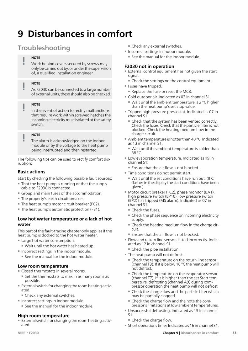
Sensor placement
BT28
BT16
BP1 BT3 BT17 BT15 BT14 BT12
BP1
BT3
BT17 BT15
BT14
BT12
High pressure switch (29 bar)BP1Temperature sensor, heating medium return lineBT3Temperature sensor, condenser supply lineBT12Temperature sensor, hot gasBT14Temperature sensor, fluid pipeBT15Temperature sensor, evaporatorBT16Temperature sensor, suction gasBT17Ambient temperature sensorBT28
NIBE™ F2030Chapter 9 | Disturbances in comfort34
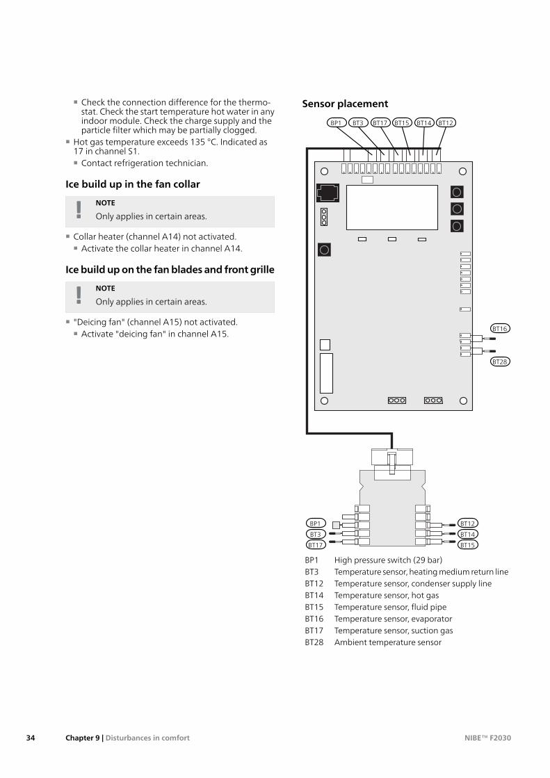
Data for temperature sensor return line (BT3),condenser supply (BT12) as well as fluid pipe(BT15)
Voltage (VDC)Resistance(kOhm)
Temperature(°C)
3.256351.0-403.240251.6-353.218182.5-303.189133.8-253.15099.22-203.10574.32-153.04756.20-102.97642.89-52.88933.0202.78925.6152.67320.02102.54115.77152.39912.51202.24510.00252.0838.045301.9166.514351.7525.306401.5874.348451.4263.583501.2782.968551.1362.467601.0072.068650.8911.739700.7851.469750.6911.246800.6071.061850.5330.908900.4690.779950.4140.672100
Data for hot gas sensor (BT14)
Voltage (V)Resistance(kOhm)
Temperature(°C)
4.81118.7404.7796.13454.7278.30504.6664.11554.5952.76604.5143.64654.4336.26704.3330.27754.2225.38804.1021.37853.9718.07903.8315.33953.6813.061003.5211.171053.369.591103.198.261153.017.131202.846.181252.675.371302.504.691352.334.10140
35Chapter 9 | Disturbances in comfortNIBE™ F2030
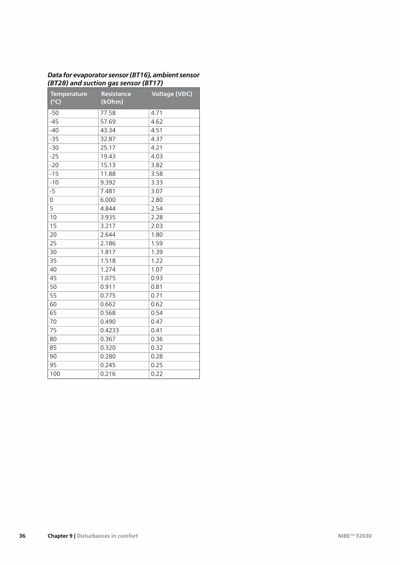
Data for evaporator sensor (BT16), ambient sensor(BT28) and suction gas sensor (BT17)
Voltage (VDC)Resistance(kOhm)
Temperature(°C)
4.7177.58-504.6257.69-454.5143.34-404.3732.87-354.2125.17-304.0319.43-253.8215.13-203.5811.88-153.339.392-103.077.481-52.806.00002.544.84452.283.935102.033.217151.802.644201.592.186251.391.817301.221.518351.071.274400.931.075450.810.911500.710.775550.620.662600.540.568650.470.490700.410.4233750.360.367800.320.320850.280.280900.250.245950.220.216100
NIBE™ F2030Chapter 9 | Disturbances in comfort36
Condensation water pipeCondensation water pipe, different lengths.
KVR 10-10, 1 meter
Part no. 067 171
KVR 10-30, 2.5 meter
Part no. 067 172
KVR 10-60, 5 meter
Part no. 067 173
Heating thermostat
VT 10
Heating thermostat
Part no. 418 801
Indoor module
VVM 310
Part no. 069 430VVM 310
With integrated EMK 310
Part no. 069 084
VVM320
Copper, 3 x 400 V
Part no. 069 108Stainless Steel, 3 x 400 V
Part no. 069 109Enamel, 3 x 400 V
With integrated EMK 300
Part no. 069 110Stainless Steel, 3 x 230 V
Part no. 069 113Stainless Steel, 1 x 230 V
Part no. 069 111Stainless Steel, 1 x 230 V
With T&P valve
Part no. 069 112
VVM 500
Part no. 069 400
SMO 20
Control module
Part no. 067 224
SMO 40
Control module
Part no. 067 225
37Chapter 10 | AccessoriesNIBE™ F2030
10 Accessories
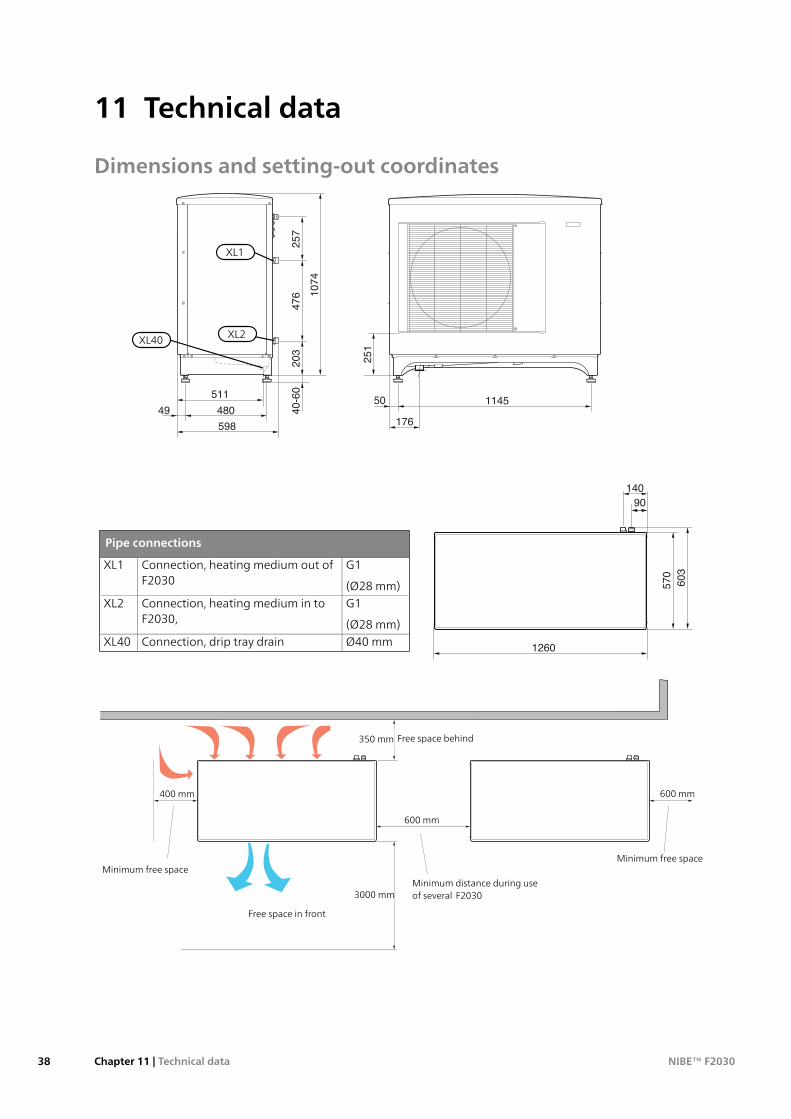
Dimensions and setting-out coordinates
251
203
476 1074
257
40-60
50
176598
48049
5111145
140
1260
90
570
603
XL2
XL1
XL40
251
203
476 1074
257
40-60
50
176598
48049
5111145
140
1260
90
570
603
Pipe connections
G1
(Ø28 mm)
Connection, heating medium out ofF2030
XL1
G1
(Ø28 mm)
Connection, heating medium in toF2030,
XL2
Ø40 mmConnection, drip tray drainXL40
40
0 m
m
Fritt utrymme bakom
Fritt utrymme framför
Min. avståndvid användningav flera F2030
600 mm
30
00
mm
400 mm
Minimalt fritt utrymme
600mm
Minimalt fritt utrymme
Minimum free space
Free space behind
Free space in front
Minimum free space
Minimum distance during useof several F2030
350 mm
400 mm
600 mm
600 mm
3000 mm
NIBE™ F2030Chapter 11 | Technical data38
11 Technical data
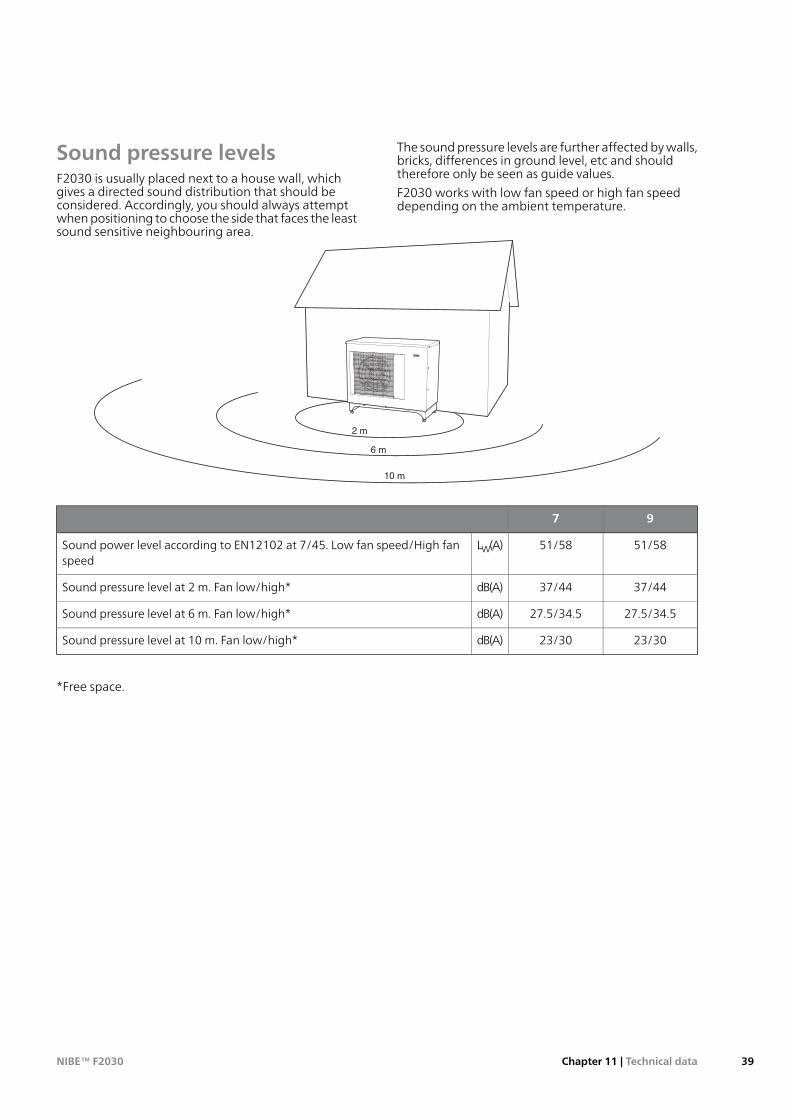
Sound pressure levelsF2030 is usually placed next to a house wall, whichgives a directed sound distribution that should beconsidered. Accordingly, you should always attemptwhen positioning to choose the side that faces the leastsound sensitive neighbouring area.
The sound pressure levels are further affected by walls,bricks, differences in ground level, etc and shouldtherefore only be seen as guide values.
F2030 works with low fan speed or high fan speeddepending on the ambient temperature.
2 m
6 m
10 m
97
51/5851/58LW(A)Sound power level according to EN12102 at 7/45. Low fan speed/High fanspeed
37/4437/44dB(A)Sound pressure level at 2 m. Fan low/high*
27.5/34.527.5/34.5dB(A)Sound pressure level at 6 m. Fan low/high*
23/3023/30dB(A)Sound pressure level at 10 m. Fan low/high*
*Free space.
39Chapter 11 | Technical dataNIBE™ F2030
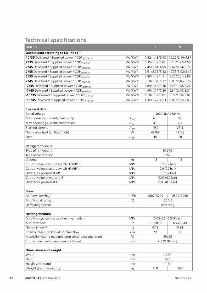
Technical specifications973x400V
Output data according to EN 14511 1)
10.22/2.10/4.877.52/1.48/5.08kW/kW/-10/35 Delivered / Supplied power / COPEN14511
8.10/1.77/4.586.35/1.32/4.81kW/kW/-7/35 Delivered / Supplied power / COPEN14511
8.42/2.24/3.767.45/1.84/4.05kW/kW/-7/45 Delivered / Supplied power / COPEN14511
10.33/3.02/3.427.61/2.25/3.38kW/kW/-7/55 Delivered / Supplied power / COPEN14511
7.75/2.01/3.865.88/1.43/4.11kW/kW/-2/35 Delivered / Supplied power / COPEN14511
8.08/2.48/3.266.10/1.81/3.37kW/kW/-2/45 Delivered / Supplied power / COPEN14511
6.46/1.98/3.264.84/1.44/3.36kW/kW/--7/35 Delivered / Supplied power / COPEN14511
6.84/2.43/2.814.96/1.77/2.80kW/kW/--7/45 Delivered / Supplied power / COPEN14511
5.77/1.88/3.074.18/1.39/3.01kW/kW/--15/35 Delivered / Supplied power / COPEN14511
6.09/2.32/2.634.35/1.72/2.53kW/kW/--15/45 Delivered / Supplied power / COPEN14511
Electrical data400V 3NAC 50 HzRated voltage
8.86.8ArmsMax operating current, heat pump
6.34.3ArmsMax operating current, compressor
23.519.2ArmsStarting current
41/6848/68WNominal output fan (low/high)1010ArmsFuse
Refrigerant circuitR407CType of refrigerantScrollType of compressor
1.91.8kgVolume3.2 (32 bar)MPaCut-out value pressure switch HP (BP10)2.9 (29 bar)MPaCut-out value pressure switch HP (BP1)-0.7 (-7 bar)MPaDifference pressostat HP
0.02 (0.2 bar)MPaCut-out value pressostat LP0.05 (0.5 bar)MPaDifference pressostat LP
Brine2500/30002500/3000m3/hAir flow (low/high)
-25/40°CMin/Max air tempReversingDefrosting system
Heating medium0.05/0.3 (0.5/3 bar)MPaMin/Max system pressure heating medium
0.24/0.490.18/0.36l/sMin/Max flow0.240.18l/sNominal flow 2)
3.92.1kPaInternal pressure drop at nominal flow65/25°CMax/Min heating medium temp continuous operation
G1 (Ø28 mm)mmConnection heating medium ext thread
Dimensions and weight1260mmWidth570mmDepth
1134mmHeight with stand165160kgWeight (excl. packaging)
NIBE™ F2030Chapter 11 | Technical data40
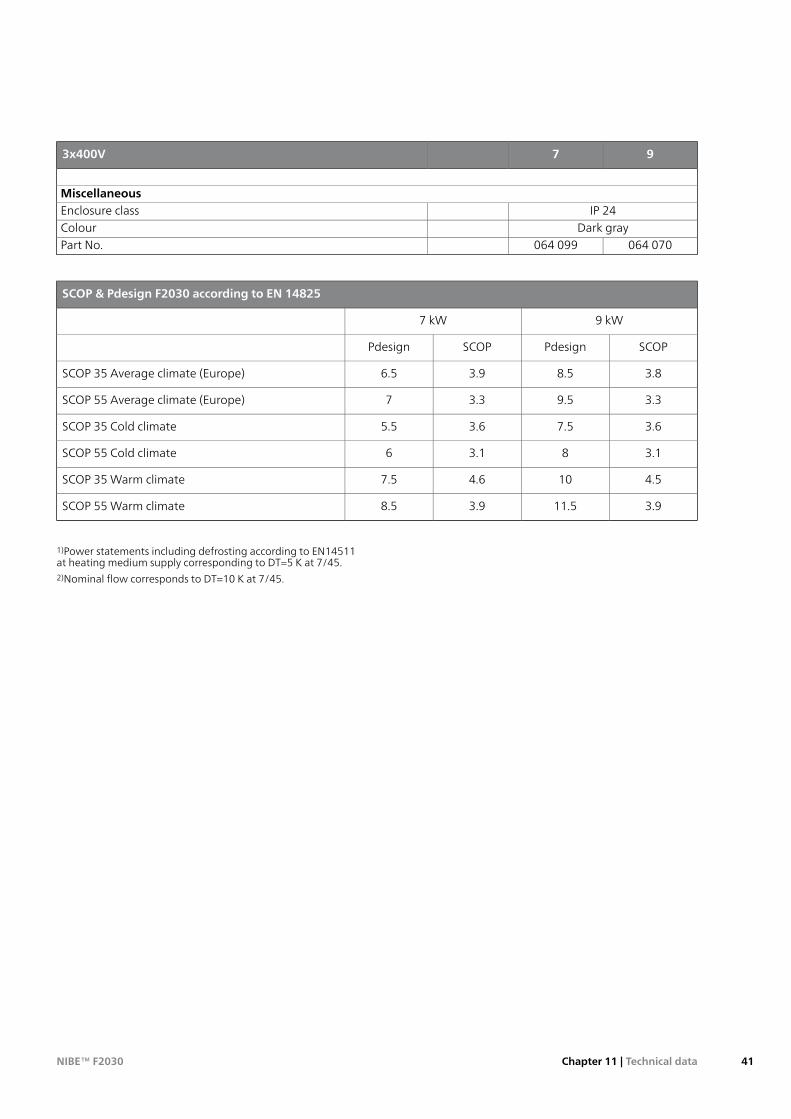
973x400V
MiscellaneousIP 24Enclosure class
Dark grayColour064 070064 099Part No.
SCOP & Pdesign F2030 according to EN 14825
9 kW7 kW
SCOPPdesignSCOPPdesign
3.88.53.96.5SCOP 35 Average climate (Europe)
3.39.53.37SCOP 55 Average climate (Europe)
3.67.53.65.5SCOP 35 Cold climate
3.183.16SCOP 55 Cold climate
4.5104.67.5SCOP 35 Warm climate
3.911.53.98.5SCOP 55 Warm climate
1)Power statements including defrosting according to EN14511at heating medium supply corresponding to DT=5 K at 7/45.2)Nominal flow corresponds to DT=10 K at 7/45.
41Chapter 11 | Technical dataNIBE™ F2030
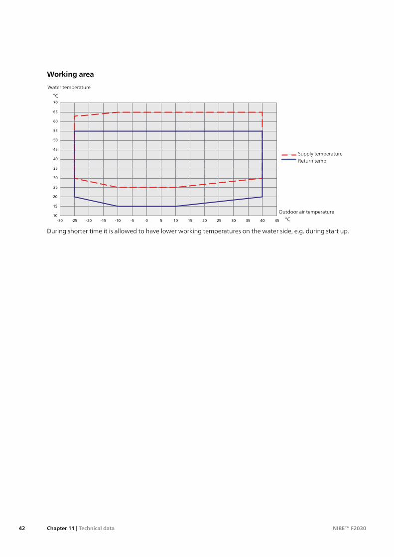
Working area
15
10
20
25
30
35
40
45
50
55
60
65
70
-20-25-30 -15 -10 -5 0 5 10 15 20 25 30 35 4540
Water temperature
°C
°C
Outdoor air temperature
0
10
20
30
40
50
60
70
-20-30 -10 0 10 20 30 40
0
10
20
30
40
50
60
70
-20-30 -10 0 10 20 30 40
Supply temperatureReturn temp
During shorter time it is allowed to have lower working temperatures on the water side, e.g. during start up.
NIBE™ F2030Chapter 11 | Technical data42
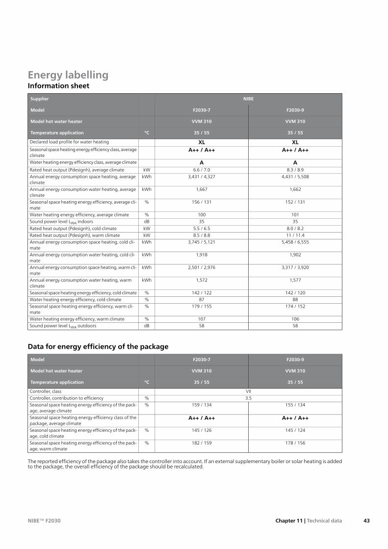
Energy labellingInformation sheet
NIBESupplier
F2030-9F2030-7Model
VVM 310VVM 310Model hot water heater
35 / 5535 / 55°CTemperature application
XLXLDeclared load profile for water heating
A++ / A++A++ / A++Seasonal space heating energy efficiency class, averageclimate
AAWater heating energy efficiency class, average climate
8.3 / 8.96.6 / 7.0kWRated heat output (Pdesignh), average climate4,431 / 5,5083,431 / 4,327kWhAnnual energy consumption space heating, average
climate1,6621,667kWhAnnual energy consumption water heating, average
climate152 / 131156 / 131%Seasonal space heating energy efficiency, average cli-
mate101100%Water heating energy efficiency, average climate3535dBSound power level LWA indoors
8.0 / 8.25.5 / 6.5kWRated heat output (Pdesignh), cold climate11 / 11.48.5 / 8.8kWRated heat output (Pdesignh), warm climate
5,458 / 6,5553,745 / 5,121kWhAnnual energy consumption space heating, cold cli-mate
1,9021,918kWhAnnual energy consumption water heating, cold cli-mate
3,317 / 3,9202,501 / 2,976kWhAnnual energy consumption space heating, warm cli-mate
1,5771,572kWhAnnual energy consumption water heating, warmclimate
142 / 120142 / 122%Seasonal space heating energy efficiency, cold climate8887%Water heating energy efficiency, cold climate
174 / 152179 / 155%Seasonal space heating energy efficiency, warm cli-mate
106107%Water heating energy efficiency, warm climate5858dBSound power level LWA outdoors
Data for energy efficiency of the package
F2030-9F2030-7Model
VVM 310VVM 310Model hot water heater
35 / 5535 / 55°CTemperature application
VIIController, class3.5%Controller, contribution to efficiency
155 / 134159 / 134%Seasonal space heating energy efficiency of the pack-age, average climate
A++ / A++A++ / A++Seasonal space heating energy efficiency class of thepackage, average climate
145 / 124145 / 126%Seasonal space heating energy efficiency of the pack-age, cold climate
178 / 156182 / 159%Seasonal space heating energy efficiency of the pack-age, warm climate
The reported efficiency of the package also takes the controller into account. If an external supplementary boiler or solar heating is addedto the package, the overall efficiency of the package should be recalculated.
43Chapter 11 | Technical dataNIBE™ F2030
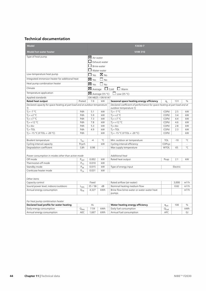
Technical documentation
F2030-7Model
VVM 310Model hot water heater
Air-water
Exhaust-water
Brine-water
Water-water
Type of heat pump
Yes NoLow-temperature heat pump
Yes NoIntegrated immersion heater for additional heat
Yes NoHeat pump combination heater
Average Cold WarmClimate
Average (55 °C) Low (35 °C)Temperature application
EN14825 / EN16147Applied standards%131ƞsSeasonal space heating energy efficiencykW7.0PratedRated heat output
Declared coefficient of performance for space heating at part load and atoutdoor temperature Tj
Declared capacity for space heating at part load and at outdoor temperatureTj
kW2.5COPdTj = -7 °CkW5.1PdhTj = -7 °CkW3.4COPdTj = +2 °CkW5.9PdhTj = +2 °CkW4.4COPdTj = +7 °CkW7.3PdhTj = +7 °CkW4.6COPdTj = +12 °CkW7.8PdhTj = +12 °CkW2.8COPdTj = bivkW5.3PdhTj = bivkW2.3COPdTj = TOLkW4.9PdhTj = TOLkWCOPdTj = -15 °C (if TOL < -20 °C)kWPdhTj = -15 °C (if TOL < -20 °C)
°C-10TOLMin. outdoor air temperature°C-4TbivBivalent temperature
-COPcycCycling interval efficiencykWPcychCycling interval capacity°C65WTOLMax supply temperature-0.98CdhDegradation coefficient
Additional heatPower consumption in modes other than active mode
kW2.1PsupRated heat outputkW0.002POFFOff mode
kW0.010PTOThermostat-off mode
ElectricType of energy inputkW0.015PSBStandby mode
kW0.031PCKCrankcase heater mode
Other items
m3/h3,000Rated airflow (air-water)FixedCapacity control
m3/h0.82Nominal heating medium flowdB35 / 58LWASound power level, indoors/outdoors
m3/hBrine flow brine-water or water-water heatpumps
kWh4,327QHEAnnual energy consumption
For heat pump combination heater
%100ƞwhWater heating energy efficiencyXLDeclared load profile for water heating
kWhQfuelDaily fuel consumptionkWh7.59QelecDaily energy consumption
GJAFCAnnual fuel consumptionkWh1,667AECAnnual energy consumption
NIBE™ F2030Chapter 11 | Technical data44
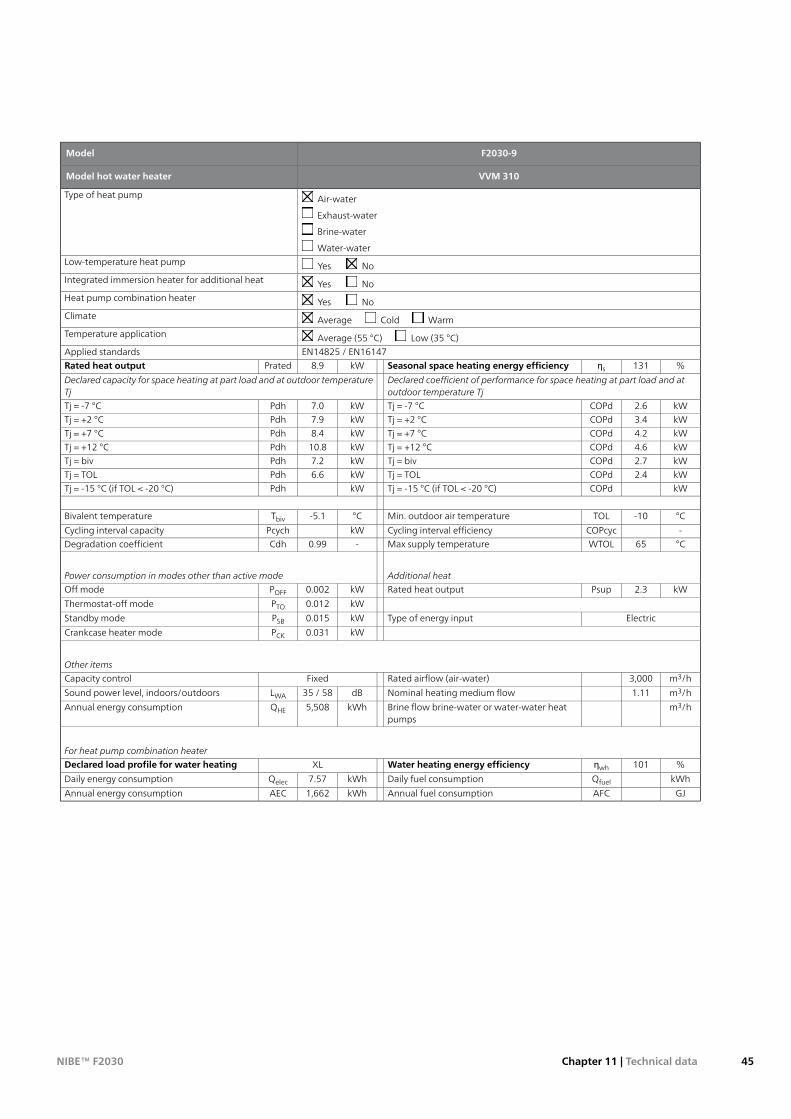
F2030-9Model
VVM 310Model hot water heater
Air-water
Exhaust-water
Brine-water
Water-water
Type of heat pump
Yes NoLow-temperature heat pump
Yes NoIntegrated immersion heater for additional heat
Yes NoHeat pump combination heater
Average Cold WarmClimate
Average (55 °C) Low (35 °C)Temperature application
EN14825 / EN16147Applied standards%131ƞsSeasonal space heating energy efficiencykW8.9PratedRated heat output
Declared coefficient of performance for space heating at part load and atoutdoor temperature Tj
Declared capacity for space heating at part load and at outdoor temperatureTj
kW2.6COPdTj = -7 °CkW7.0PdhTj = -7 °CkW3.4COPdTj = +2 °CkW7.9PdhTj = +2 °CkW4.2COPdTj = +7 °CkW8.4PdhTj = +7 °CkW4.6COPdTj = +12 °CkW10.8PdhTj = +12 °CkW2.7COPdTj = bivkW7.2PdhTj = bivkW2.4COPdTj = TOLkW6.6PdhTj = TOLkWCOPdTj = -15 °C (if TOL < -20 °C)kWPdhTj = -15 °C (if TOL < -20 °C)
°C-10TOLMin. outdoor air temperature°C-5.1TbivBivalent temperature
-COPcycCycling interval efficiencykWPcychCycling interval capacity°C65WTOLMax supply temperature-0.99CdhDegradation coefficient
Additional heatPower consumption in modes other than active mode
kW2.3PsupRated heat outputkW0.002POFFOff mode
kW0.012PTOThermostat-off mode
ElectricType of energy inputkW0.015PSBStandby mode
kW0.031PCKCrankcase heater mode
Other items
m3/h3,000Rated airflow (air-water)FixedCapacity control
m3/h1.11Nominal heating medium flowdB35 / 58LWASound power level, indoors/outdoors
m3/hBrine flow brine-water or water-water heatpumps
kWh5,508QHEAnnual energy consumption
For heat pump combination heater
%101ƞwhWater heating energy efficiencyXLDeclared load profile for water heating
kWhQfuelDaily fuel consumptionkWh7.57QelecDaily energy consumption
GJAFCAnnual fuel consumptionkWh1,662AECAnnual energy consumption
45Chapter 11 | Technical dataNIBE™ F2030
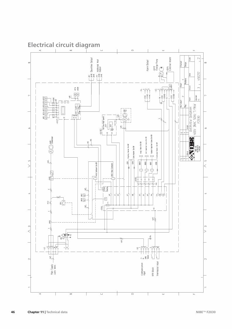
Electrical circuit diagram
NIBE™ F2030Chapter 11 | Technical data46
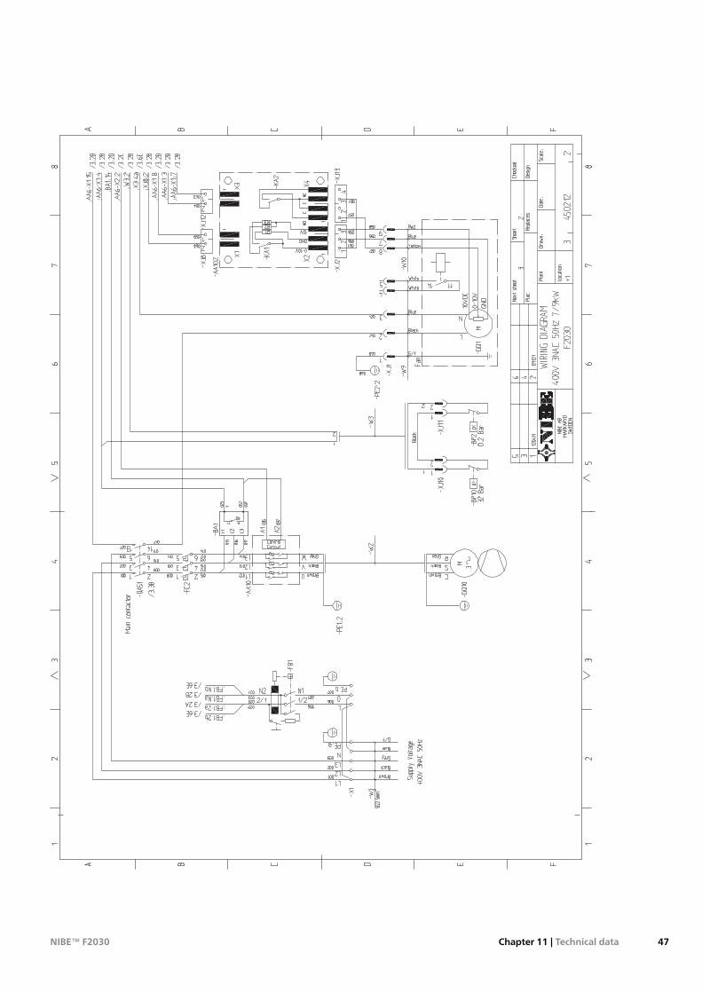
47Chapter 11 | Technical dataNIBE™ F2030
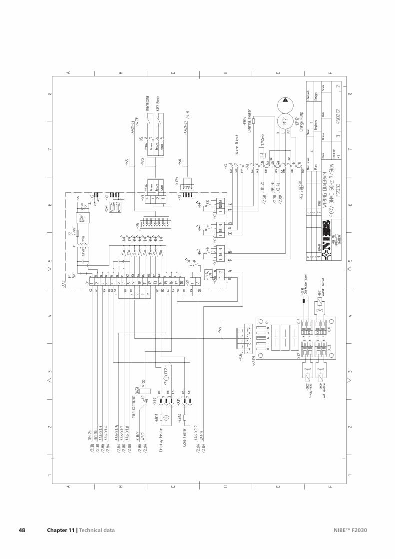
NIBE™ F2030Chapter 11 | Technical data48
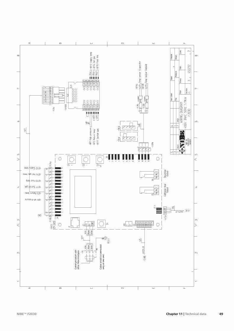
49Chapter 11 | Technical dataNIBE™ F2030
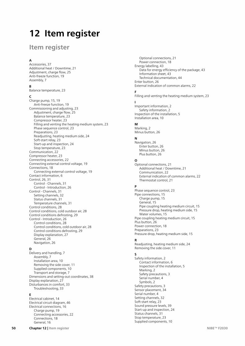
Item register
AAccessories, 37Additional heat / Downtime, 21Adjustment, charge flow, 25Anti-freeze function, 19Assembly, 7
BBalance temperature, 23
CCharge pump, 15, 19
Anti-freeze function, 19Commissioning and adjusting, 23
Adjustment, charge flow, 25Balance temperature, 23Compressor heater, 23Filling and venting the heating medium system, 23Phase sequence control, 23Preparations, 23Readjusting, heating medium side, 24Soft-start relay, 23Start-up and inspection, 24Stop temperature, 23
Communication, 22Compressor heater, 23Connecting accessories, 22Connecting external control voltage, 19Connections, 18
Connecting external control voltage, 19Contact information, 6Control, 26, 31
Control - Channels, 31Control - Introduction, 26
Control - Channels, 31Setting channels, 32Status channels, 31Temperature channels, 31
Control conditions, 28Control conditions, cold outdoor air, 28Control conditions defrosting, 29Control - Introduction, 26
Control conditions, 28Control conditions, cold outdoor air, 28Control conditions defrosting, 29Display explanation, 27General, 26Navigation, 26
DDelivery and handling, 7
Assembly, 7Installation area, 10Removing the side cover, 11Supplied components, 10Transport and storage, 7
Dimensions and setting-out coordinates, 38Display explanation, 27Disturbances in comfort, 33
Troubleshooting, 33
EElectrical cabinet, 14Electrical circuit diagram, 46Electrical connections, 16
Charge pump, 19Connecting accessories, 22Connections, 18General, 16
Optional connections, 21Power connection, 18
Energy labelling, 43Data for energy efficiency of the package, 43Information sheet, 43Technical documentation, 44
Enter button, 26External indication of common alarms, 22
FFilling and venting the heating medium system, 23
IImportant information, 2
Safety information, 2Inspection of the installation, 5Installation area, 10
MMarking, 2Minus button, 26
NNavigation, 26
Enter button, 26Minus button, 26Plus button, 26
OOptional connections, 21
Additional heat / Downtime, 21Communication, 22External indication of common alarms, 22Thermostat control, 21
PPhase sequence control, 23Pipe connections, 15
Charge pump, 15General, 15Pipe coupling heating medium circuit, 15Pressure drop, heating medium side, 15Water volumes, 15
Pipe coupling heating medium circuit, 15Plus button, 26Power connection, 18Preparations, 23Pressure drop, heating medium side, 15
RReadjusting, heating medium side, 24Removing the side cover, 11
SSafety information, 2
Contact information, 6Inspection of the installation, 5Marking, 2Safety precautions, 3Serial number, 4Symbols, 2
Safety precautions, 3Sensor placement, 34Serial number, 4Setting channels, 32Soft-start relay, 23Sound pressure levels, 39Start-up and inspection, 24Status channels, 31Stop temperature, 23Supplied components, 10
NIBE™ F2030Chapter 12 | Item register50
12 Item register
Symbols, 2
TTechnical data, 38
Dimensions and setting-out coordinates, 38Electrical circuit diagram, 46Sound pressure levels, 39Technical Data, 40
Technical Data, 40Temperature channels, 31The heat pump design, 12
Component list electrical cabinet, 14Component location electrical cabinet, 14Component locations, 12List of components, 12–13
Thermostat control, 21Transport and storage, 7Troubleshooting, 33
Sensor placement, 34
51Chapter 12 | Item registerNIBE™ F2030

SE
ÅtervinningLämna avfallshanteringen av emballaget till den installatör som installerade produkten eller till särskildaavfallsstationer.
När produkten är uttjänt får den inte slängas bland vanligt hushållsavfall. Den ska lämnas in till särskildaavfallsstationer eller till återförsäljare som tillhandahåller denna typ av service.
Felaktig avfallshantering av produkten från användarens sida gör att administrativa påföljder tillämpasi enlighet med gällande lagstiftning.
GB
RecoveryLeave the disposal of the packaging to the installerwho installed the product or to specialwaste stations.
Do not dispose of used products with normal householdwaste. It must be disposed of at a special wastestation or dealer who provides this type of service.
Improper disposal of theproduct by theuser results in administrative penalties in accordancewith currentlegislation.
DE
RecyclingÜbergeben Sie den Verpackungsabfall dem Installateur, der das Produkt installiert hat, oder bringen Sieihn zu den entsprechenden Abfallstationen.
Wenn das Produkt das Ende seiner Lebensdauer erreicht hat, darf es nicht über den normalen Hausmüllentsorgtwerden. Stattdessenmussesbei speziellenEntsorgungseinrichtungenoderHändlernabgegebenwerden, die diese Dienstleistung anbieten.
Eine unsachgemäße Entsorgung des Produkts durch den Benutzer zieht Verwaltungsstrafen gemäßgeltendem Recht nach sich.

WS name: -GemensamtWS version: a74 (working edition)Publish date: 2015-08-31 08:25
231115
NIBE AB Sweden
Hannabadsvägen 5Box 14 SE-285 21 [email protected]