Embed Size (px)
Citation preview
Installer manual
LEK
VPB/VPBS UKHot water heater
IHB GB 1237-7031290

Table of Contents1 Important information 2
Safety information 2
2 Delivery and handling 6Transport 6
Assembly 6
Supplied components 6
Removing the covers 7
3 The water heater design 8
4 Pipe connections 10General 10
Dimensions and pipe connections 11
T&P valve 13
Heat pump 13
Sun 13
Cold and hot water 14
Installation alternative 14
5 Electrical installation 16Sensors 16
Temperature limiter 17
6 Commissioning and adjusting 18Filling and venting 18
Start-up and inspection 19
7 Service and maintenance 20Maintenance 20
Service actions 20
8 Technical data 21Dimensions and setting-out coordinates 21
Technical specifications 22
Item register 25
1Table of Contents |VPB/VPBS UK
Safety informationThis manual describes installation and service proceduresfor implementation by specialists.
This appliance is not intended for use by persons (includ-ing children) with reduced physical, sensory or mentalcapabilities, or lack of experience and knowledge, unlessthey have been given supervision or instruction concern-ing use of the appliance by a person responsible for theirsafety.
Children should be supervised to ensure that they do notplay with the appliance.
Rights to make any design or technical modifications arereserved.
©NIBE 2012.
Symbols
NOTE
This symbol indicates danger to machine orperson.
Caution
This symbol indicates important informationabout what you should observe when maintain-ing your installation.
TIP
This symbol indicates tips on how to facilitateusing the product.
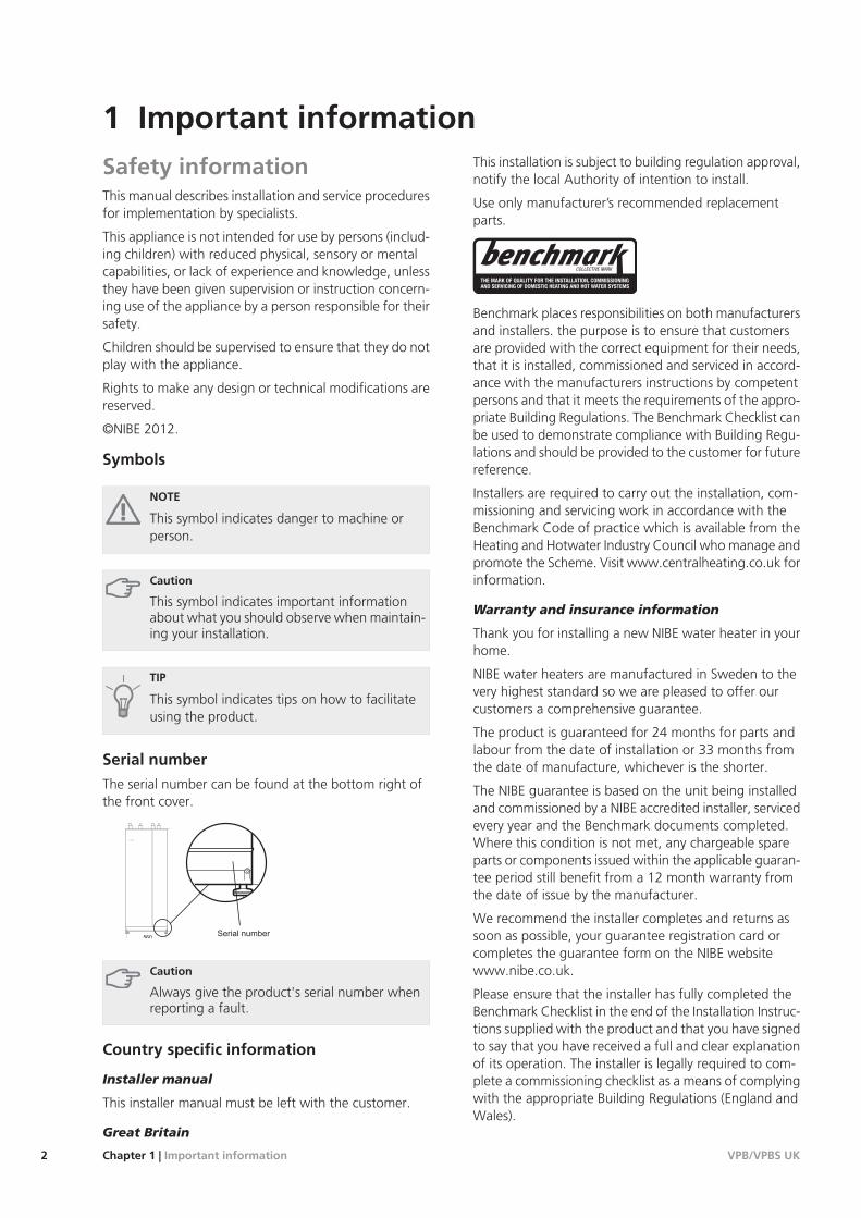
Serial number
The serial number can be found at the bottom right ofthe front cover.
560
Caution
Always give the product's serial number whenreporting a fault.
Country specific information
Installer manual
This installer manual must be left with the customer.
Great Britain
This installation is subject to building regulation approval,notify the local Authority of intention to install.
Use only manufacturer’s recommended replacementparts.
Benchmark places responsibilities on both manufacturersand installers. the purpose is to ensure that customersare provided with the correct equipment for their needs,that it is installed, commissioned and serviced in accord-ance with the manufacturers instructions by competentpersons and that it meets the requirements of the appro-priate Building Regulations. The Benchmark Checklist canbe used to demonstrate compliance with Building Regu-lations and should be provided to the customer for futurereference.
Installers are required to carry out the installation, com-missioning and servicing work in accordance with theBenchmark Code of practice which is available from theHeating and Hotwater Industry Council who manage andpromote the Scheme. Visit www.centralheating.co.uk forinformation.
Warranty and insurance information
Thank you for installing a new NIBE water heater in yourhome.
NIBE water heaters are manufactured in Sweden to thevery highest standard so we are pleased to offer ourcustomers a comprehensive guarantee.
The product is guaranteed for 24 months for parts andlabour from the date of installation or 33 months fromthe date of manufacture, whichever is the shorter.
The NIBE guarantee is based on the unit being installedand commissioned by a NIBE accredited installer, servicedevery year and the Benchmark documents completed.Where this condition is not met, any chargeable spareparts or components issued within the applicable guaran-tee period still benefit from a 12 month warranty fromthe date of issue by the manufacturer.
We recommend the installer completes and returns assoon as possible, your guarantee registration card orcompletes the guarantee form on the NIBE websitewww.nibe.co.uk.
Please ensure that the installer has fully completed theBenchmark Checklist in the end of the Installation Instruc-tions supplied with the product and that you have signedto say that you have received a full and clear explanationof its operation. The installer is legally required to com-plete a commissioning checklist as a means of complyingwith the appropriate Building Regulations (England andWales).
VPB/VPBS UKChapter 1 | Important information2
1 Important information

All installations must be notified to Local Area BuildingControl either directly or through a Competent PersonsScheme. A Building Regulations Compliance Certificatewill then be issued to the customer who should, on re-ceipt, write the Notification Number on the BenchmarkChecklist.
This product should be serviced regularly to optimise itssafety, efficiency and performance. The service engineershould complete the relevant Service Record on theBenchmark Checklist after each service.
The Benchmark Checklist may be required in the eventof any warranty work and as supporting documentationrelating to home improvements in the optional documentssection of the Home Information Pack.
3Chapter 1 | Important informationVPB/VPBS UK

VPB/VPBS UKChapter 1 | Important information4
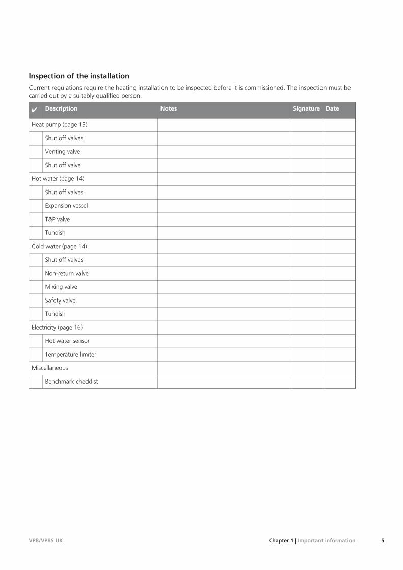
Inspection of the installation
Current regulations require the heating installation to be inspected before it is commissioned. The inspection must becarried out by a suitably qualified person.
DateSignatureNotesDescription✔
Heat pump (page 13)
Shut off valves
Venting valve
Shut off valve
Hot water (page 14)
Shut off valves
Expansion vessel
T&P valve
Tundish
Cold water (page 14)
Shut off valves
Non-return valve
Mixing valve
Safety valve
Tundish
Electricity (page 16)
Hot water sensor
Temperature limiter
Miscellaneous
Benchmark checklist
5Chapter 1 | Important informationVPB/VPBS UK
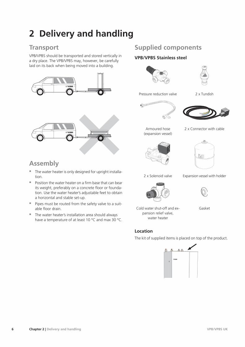
TransportVPB/VPBS should be transported and stored vertically ina dry place. The VPB/VPBS may, however, be carefullylaid on its back when being moved into a building.
R
0
R0
AssemblyThe water heater is only designed for upright installa-tion.
Position the water heater on a firm base that can bearits weight, preferably on a concrete floor or founda-tion. Use the water heater’s adjustable feet to obtaina horizontal and stable set-up.
Pipes must be routed from the safety valve to a suit-able floor drain.
The water heater’s installation area should alwayshave a temperature of at least 10 °C and max 30 °C.
Supplied componentsVPB/VPBS Stainless steel
LEK
LEK
2 x TundishPressure reduction valve
LEK
LEK
2 x Connector with cableArmoured hose(expansion vessel)
LEK
LEK
Expansion vessel with holder2 x Solenoid valve
LE
K
GasketCold water shut-off and ex-pansion relief valve,
water heater
Location
The kit of supplied items is placed on top of the product.
VPB/VPBS UKChapter 2 | Delivery and handling6
2 Delivery and handling
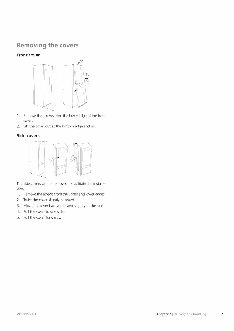
Removing the coversFront cover
1
2L
EK
LE
K
1. Remove the screws from the lower edge of the frontcover.
2. Lift the cover out at the bottom edge and up.
Side covers
LE
K
LE
K
LE
K
The side covers can be removed to facilitate the installa-tion.
1. Remove the screws from the upper and lower edges.
2. Twist the cover slightly outward.
3. Move the cover backwards and slightly to the side.
4. Pull the cover to one side.
5. Pull the cover forwards.
7Chapter 2 | Delivery and handlingVPB/VPBS UK
LEK LEK
VPB/VPBS UKChapter 3 | The water heater design8
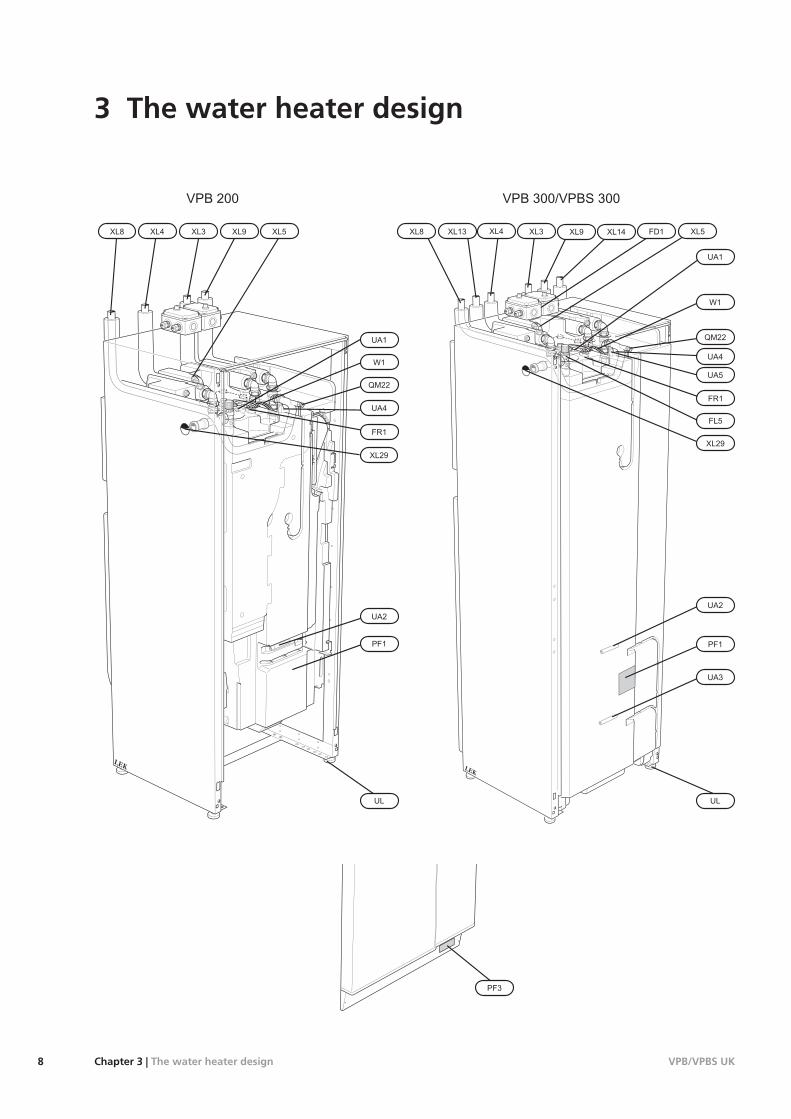
3 The water heater design
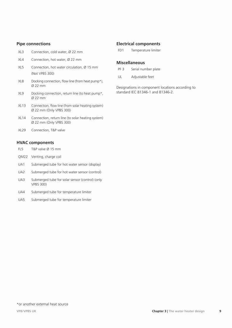
Pipe connections
Connection, cold water, Ø 22 mmXL3
Connection, hot water, Ø 22 mmXL4
Connection, hot water circulation, Ø 15 mm
(Not VPBS 300)
XL5
Docking connection, flow line (from heat pump*),Ø 22 mm
XL8
Docking connection, return line (to heat pump*,Ø 22 mm
XL9
Connection, flow line (from solar heating system)Ø 22 mm (Only VPBS 300)
XL13
Connection, return line (to solar heating system)Ø 22 mm (Only VPBS 300)
XL14
Connection, T&P valveXL29
HVAC componentsT&P valve Ø 15 mmFL5
Venting, charge coilQM22
Submerged tube for hot water sensor (display)UA1
Submerged tube for hot water sensor (control)UA2
Submerged tube for solar sensor (control) (onlyVPBS 300)
UA3
Submerged tube for temperature limiterUA4
Submerged tube for temperature limiterUA5
Electrical componentsTemperature limiterFD1
MiscellaneousSerial number platePF 3
Adjustable feetUL
Designations in component locations according tostandard IEC 81346-1 and 81346-2.
*or another external heat source
9Chapter 3 | The water heater designVPB/VPBS UK

GeneralPipe installation must be carried out in accordance withcurrent norms and directives.
Internal support bushes should be fitted when a plasticpipe or annealed copper pipe is used. The water heatermust be fitted with the requisite valves, such as a safetyvalve, shut-off valve, non-return valve, and vacuum valve.An overflow pipe must be routed from the safety valveto a suitable drain. The size of the overflow pipe must bethe same as on the safety valve. Route the overflow pipefrom the safety valve enclosed along its entire length andensure that it is frost proof. The outlet of the overflowpipe should be visible and clearly away from any electricalcomponents.
Overflow water from the safety valves goes via non-pressurised collecting pipes to a drain so that hot watersplashes cannot cause injury. These non-pressurised col-lecting pipes shall not be used for anything else. A dis-charge pipe from the tundish connected to the expansionrelief valve (safety valve) shall also be connected to a drainin the same way.
Please note that the connection of the T&P-valve shouldnot be used for any other purpose.
Valves may not be positioned between the expansionvalve and the vessel.
Discharge pipes from tundishes shall have av verticalsection of pipe at least 300 mm long, before any elbowsor bends in the pipework (see following picture).
600 mm maximum
Tundish
Metal discharge pipe fromtemperature relief valve to tundish.
Safety device(e.g. temperaturerelief valve).
300 mmminimum
Metal discharge pipe from tundish,with continous fall.
Possible wall
Discharge belowfixed grating.
Trapped gulley
Fixed grating
NOTE
The expansion vessel accomodates expansionthat results from heating the water inside theunit. The expansion vessel must be connectedbetween the expansion valve and the cylinder.The location of the expansion vessel should allowaccess to recharge the pressure as and whennecessary.
Resistance created byeach elbow or bend
Maximum resistanceallowed, expressedas a lenght ofstraight pipe (i.e. noelbows or bends)
Minimum size of dis-charge pipe fromtundish
Minimum size of dis-charge pipe
Valve outlet size
0.8 mmup to 9 m22 mm15 mmG1/2
1.0 mmup to 18 m28 mm15 mmG1/2
1.4 mmup to 27 m35 mm15 mmG1/2
1.0 mmup to 9 m28 mm22 mmG3/4
1.4 mmup to 18 m35 mm22 mmG3/4
1.7 mmup to 27 m42 mm22 mmG3/4
1.4 mmup to 9 m35 mm28 mmG1
1.7 mmup to 18 m42 mm28 mmG1
2.3 mmup to 27 m54 mm28 mmG1
Hard water areas
Usually, there should not be a problem in installingVPB/VPBS in areas of hard water as the operating temper-ature is 50-60 °C.
Cleaning the climate system
When the water heater and the climate system have beenfilled with water, VPB/VPBS must operate at maximumnormal temperature for at least one hour. Thereafter thesystem must be drained of water and refilled.
VPB/VPBS UKChapter 4 | Pipe connections10
4 Pipe connections
Emptying the system by
1. Open external filler valve and external drain valve.
2. Flush the system for some minute. Watch out forwater splashes from the safety valve.
3. Close the valves and check the stainer.
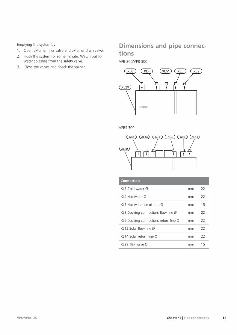
Dimensions and pipe connec-tionsVPB 200/VPB 300
VPBS 300
Connection
22mmXL3 Cold water Ø
22mmXL4 Hot water Ø
15mmXL5 Hot water circulation Ø
22mmXL8 Docking connection, flow line Ø
22mmXL9 Docking connection, return line Ø
22mmXL13 Solar flow line Ø
22mmXL14 Solar return line Ø
15mmXL29 T&P valve Ø
11Chapter 4 | Pipe connectionsVPB/VPBS UK
600
600
30
60
205
135
535
480
25
390
80
100
210
430
440
80
75
440
430
VPB/VPBS UKChapter 4 | Pipe connections12
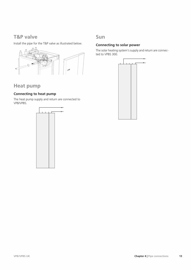
T&P valveInstall the pipe for the T&P valve as illustrated below.
Heat pumpConnecting to heat pump
The heat pump supply and return are connected toVPB/VPBS.
SunConnecting to solar power
The solar heating system's supply and return are connec-ted to VPBS 300.
13Chapter 4 | Pipe connectionsVPB/VPBS UK
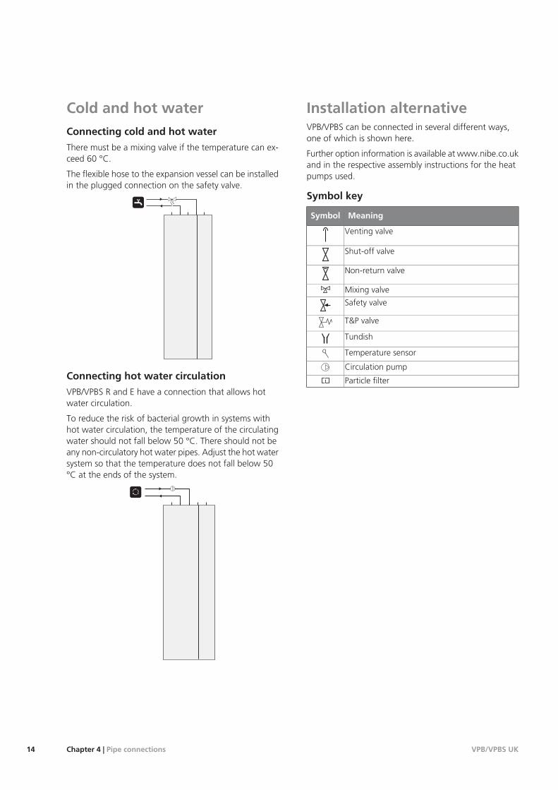
Cold and hot waterConnecting cold and hot water
There must be a mixing valve if the temperature can ex-ceed 60 °C.
The flexible hose to the expansion vessel can be installedin the plugged connection on the safety valve.
Connecting hot water circulation
VPB/VPBS R and E have a connection that allows hotwater circulation.
To reduce the risk of bacterial growth in systems withhot water circulation, the temperature of the circulatingwater should not fall below 50 °C. There should not beany non-circulatory hot water pipes. Adjust the hot watersystem so that the temperature does not fall below 50°C at the ends of the system.
Installation alternativeVPB/VPBS can be connected in several different ways,one of which is shown here.
Further option information is available at www.nibe.co.ukand in the respective assembly instructions for the heatpumps used.
Symbol key
MeaningSymbol
Venting valve
Shut-off valve
Non-return valve
Mixing valve
Safety valve
T&P valve
Tundish
Temperature sensor
Circulation pump
Particle filter
VPB/VPBS UKChapter 4 | Pipe connections14
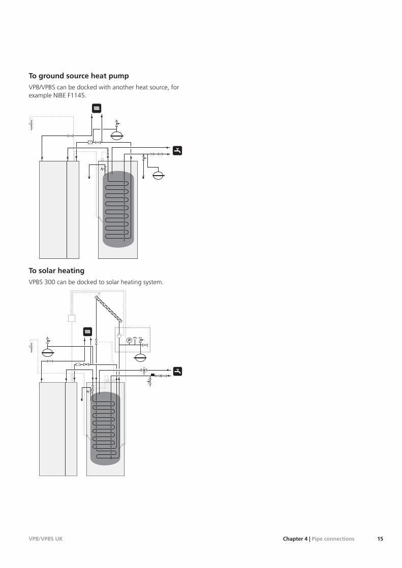
To ground source heat pump
VPB/VPBS can be docked with another heat source, forexample NIBE F1145.
To solar heating
VPBS 300 can be docked to solar heating system.
T
P
15Chapter 4 | Pipe connectionsVPB/VPBS UK
NOTE
Electrical installation and service must be carriedout under the supervision of a qualified electri-cian. Electrical installation and wiring must becarried out in accordance with the stipulationsin force.
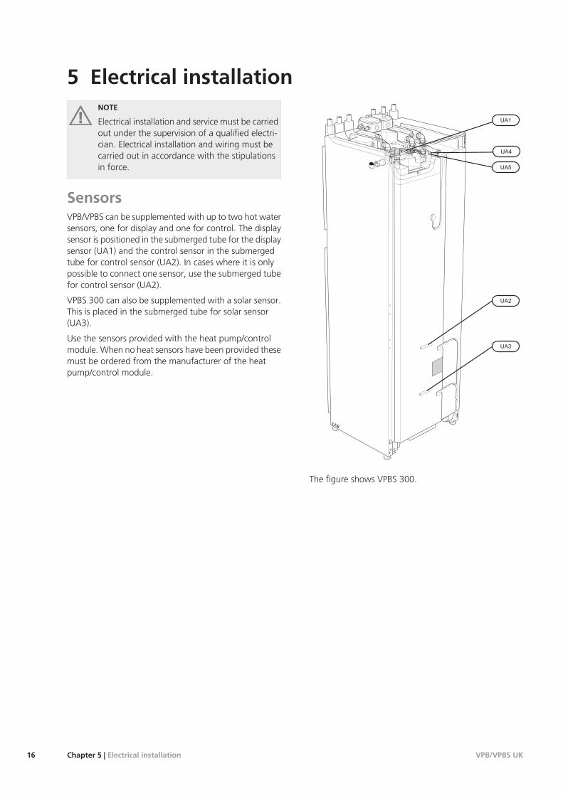
SensorsVPB/VPBS can be supplemented with up to two hot watersensors, one for display and one for control. The displaysensor is positioned in the submerged tube for the displaysensor (UA1) and the control sensor in the submergedtube for control sensor (UA2). In cases where it is onlypossible to connect one sensor, use the submerged tubefor control sensor (UA2).
VPBS 300 can also be supplemented with a solar sensor.This is placed in the submerged tube for solar sensor(UA3).
Use the sensors provided with the heat pump/controlmodule. When no heat sensors have been provided thesemust be ordered from the manufacturer of the heatpump/control module.
LEK
The figure shows VPBS 300.
VPB/VPBS UKChapter 5 | Electrical installation16
5 Electrical installation
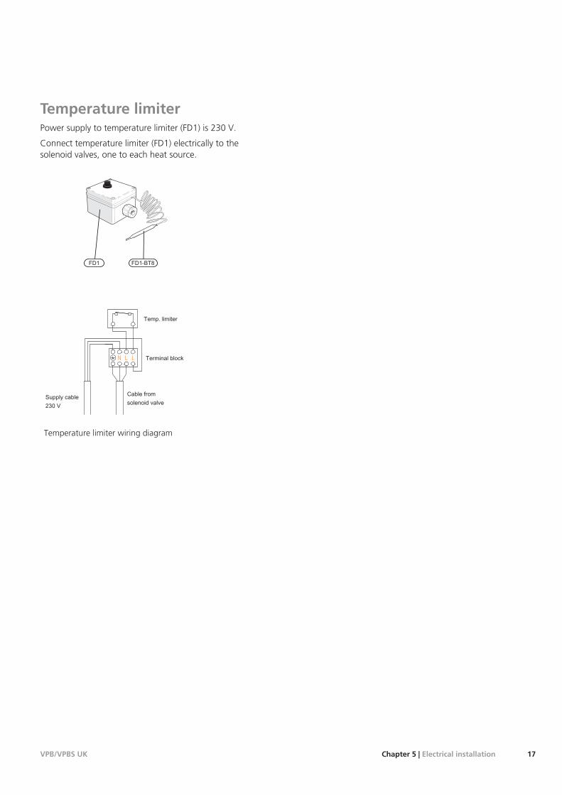
Temperature limiterPower supply to temperature limiter (FD1) is 230 V.
Connect temperature limiter (FD1) electrically to thesolenoid valves, one to each heat source.
LEK
Temperature limiter wiring diagram
17Chapter 5 | Electrical installationVPB/VPBS UK
NOTE
At the time of commissioning, complete all rel-evant sections of the Benchmark Checklist loc-ated at the back of this document.
Completion of the Benchmark Checklist is acondition of warranty. For full terms and condi-tions of warranty, please see our websitewww.nibe.co.uk.
Filling and ventingFilling the hot water heater
1. Open a hot water tap in the house.
2. Fill the hot water heater through the cold waterconnection (XL3).
3. When the water that comes out of the hot water tapis no longer mixed with air, the water heater is fulland the tap can be closed.
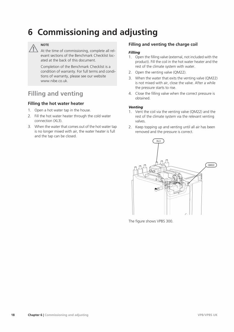
Filling and venting the charge coil
Filling1. Open the filling valve (external, not included with the
product). Fill the coil in the hot water heater and therest of the climate system with water.
2. Open the venting valve (QM22).
3. When the water that exits the venting valve (QM22)is not mixed with air, close the valve. After a whilethe pressure starts to rise.
4. Close the filling valve when the correct pressure isobtained.
Venting1. Vent the coil via the venting valve (QM22) and the
rest of the climate system via the relevant ventingvalves.
2. Keep topping up and venting until all air has beenremoved and the pressure is correct.
The figure shows VPBS 300.
VPB/VPBS UKChapter 6 | Commissioning and adjusting18
6 Commissioning and adjusting
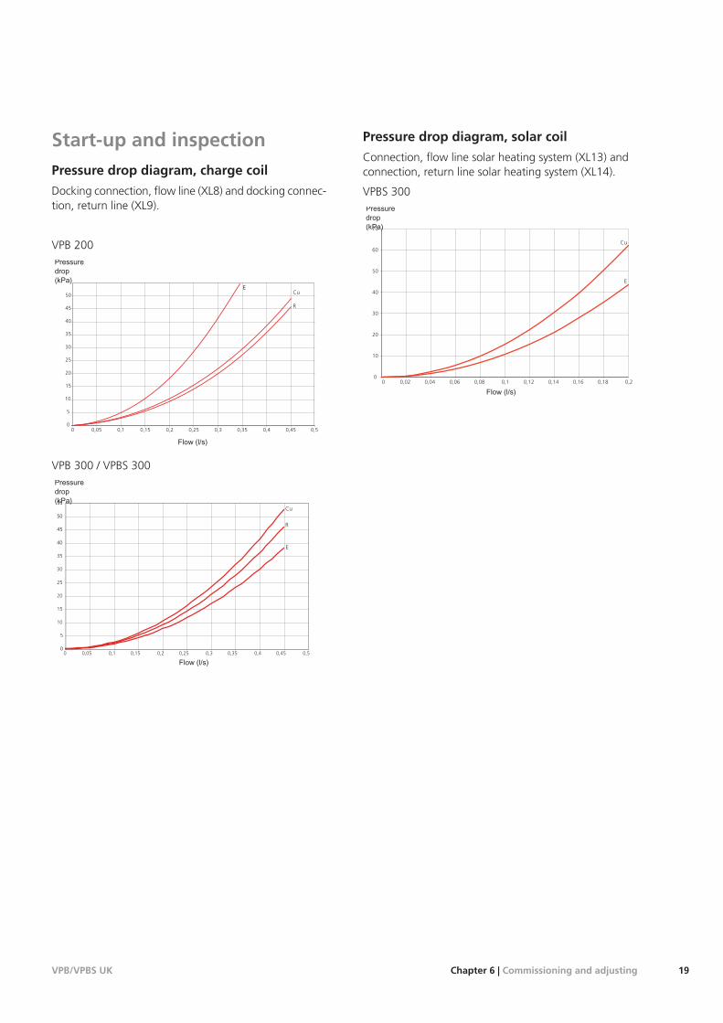
Start-up and inspectionPressure drop diagram, charge coil
Docking connection, flow line (XL8) and docking connec-tion, return line (XL9).
VPB 200
ECu
0 0,05 0,1 0,15 0,2 0,25 0,3 0,35 0,4 0,45 0,5
5
0
10
15
20
25
30
40
35
45
50
Tryckfall(kPa)
Flöde (l/s)
R
VPB 300 / VPBS 300
0
5
10
15
20
25
30
35
40
45
50
55
0 0,05 0,1 0,15 0,2 0,25 0,3 0,35 0,4 0,45 0,5
Tryckfall(kPa)
Cu
R
E
Pressure drop diagram, solar coil
Connection, flow line solar heating system (XL13) andconnection, return line solar heating system (XL14).
VPBS 300
0
10
20
30
40
50
60
70
0 0,02 0,04 0,06 0,08 0,1 0,12 0,14 0,16 0,18 0,2
Cu
E
19Chapter 6 | Commissioning and adjustingVPB/VPBS UK
NOTE
After servicing, complete the relevant ServiceInterval Record section of the BenchmarkChecklist located at the back of this document.
Completion of the Service Interval Record is acondition of warranty. For full terms and condi-tions of warranty, please see our websitewww.nibe.co.uk.
NOTE
Any servicing must be carried out by a compet-ent person.
MaintenanceGeneral inspection
Check the following:
1. Condition of casing.
2. Electrical connections.
3. Pipe connections.
Correct any fault before continuing.
Hot water heater
Check the following:
1. Expansion relief valve.
2. T&P valve.
3. Discharge pipe.
4. Expansion vessel.
Correct any fault before continuing.
Service actionsSafety valves
The function of the safety valves must be checked regu-larly. Perform checks as follows:
1. Open the valve by turning the knob anti-clockwisecarefully.
2. Check that water flows through the valve.
3. Close the valve by releasing it. If it does not closeautomatically when released, turn it anti-clockwiseslightly.
NOTE
Do not remove or adjust any components thatare part of this pressurised water heater. Contactyour installer!
NOTE
If this pressurised water heater develops a fault,e.g. a flow of hot water from the overflow pipe,turn the heat pump off and contact your in-staller.
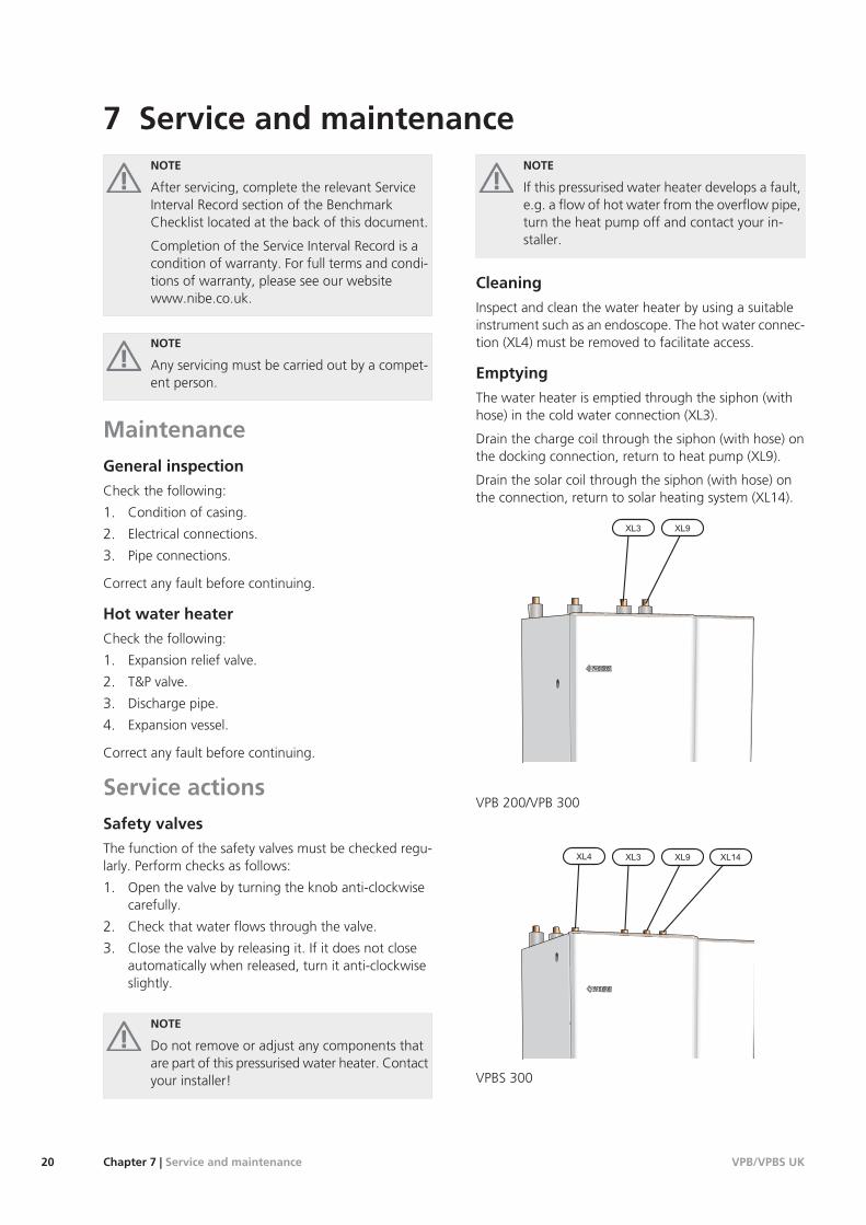
Cleaning
Inspect and clean the water heater by using a suitableinstrument such as an endoscope. The hot water connec-tion (XL4) must be removed to facilitate access.
Emptying
The water heater is emptied through the siphon (withhose) in the cold water connection (XL3).
Drain the charge coil through the siphon (with hose) onthe docking connection, return to heat pump (XL9).
Drain the solar coil through the siphon (with hose) onthe connection, return to solar heating system (XL14).
VPB 200/VPB 300
VPBS 300
VPB/VPBS UKChapter 7 | Service and maintenance20
7 Service and maintenance
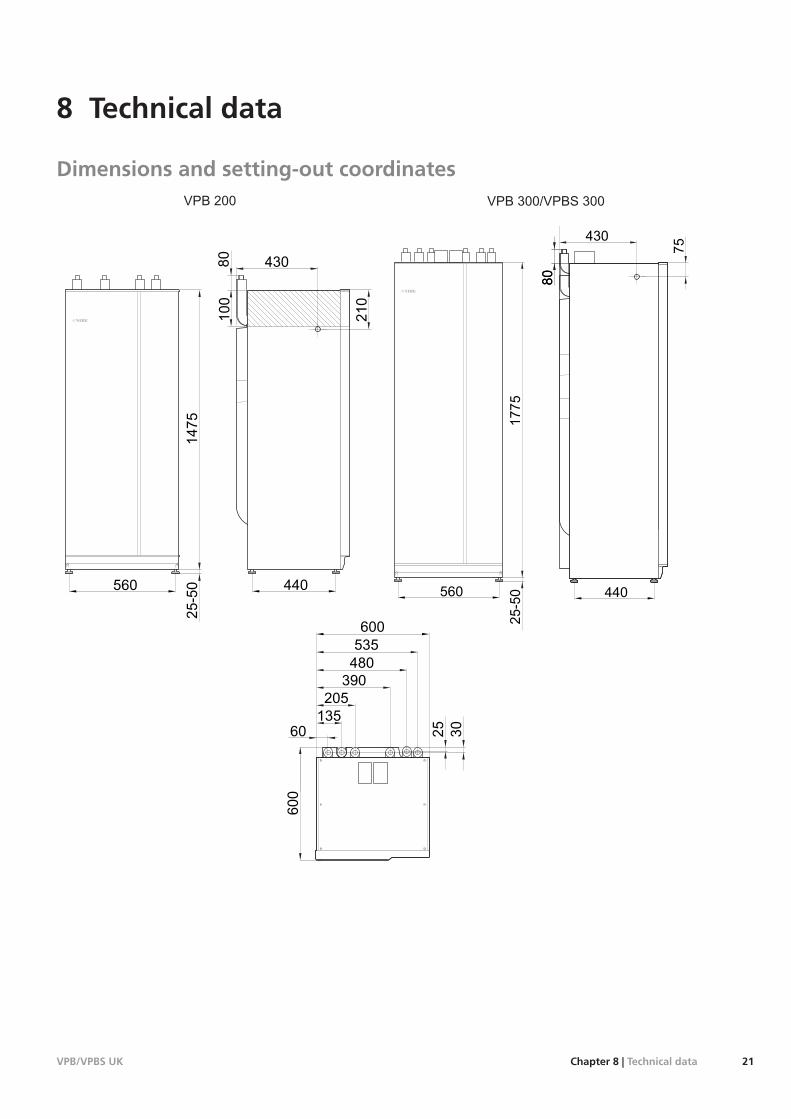
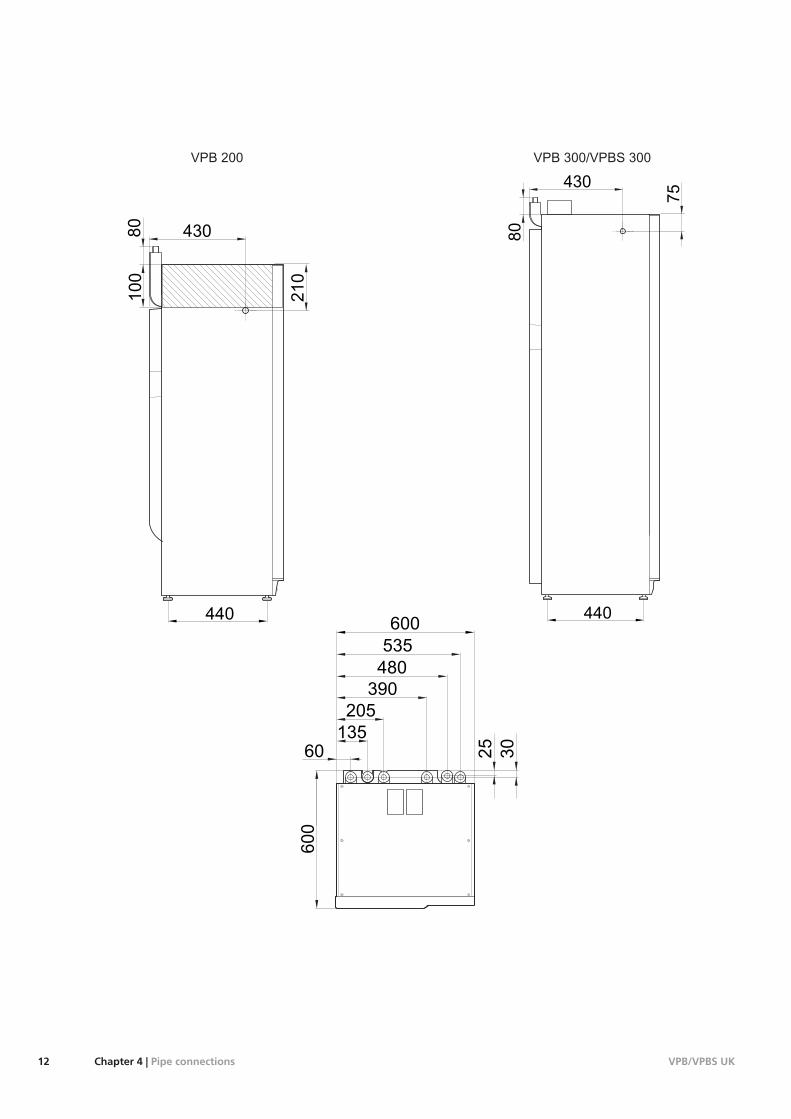
Dimensions and setting-out coordinates
80
100
210
430
440
80
430
440
75
80
25-50
1475
560
25-50
1775
560
600
600
30
60
205
135
535
480
25
390
21Chapter 8 | Technical dataVPB/VPBS UK
8 Technical data
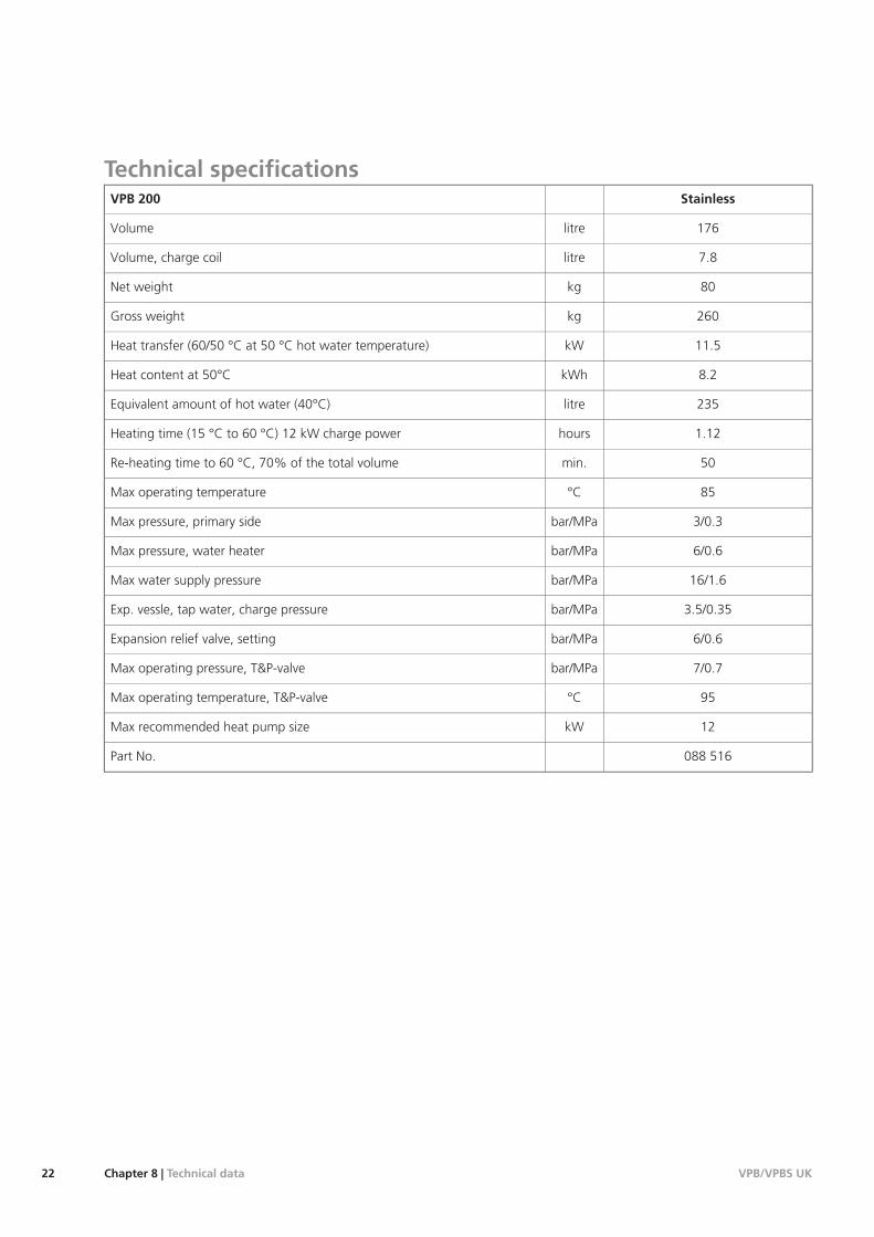
Technical specificationsStainlessVPB 200
176litreVolume
7.8litreVolume, charge coil
80kgNet weight
260kgGross weight
11.5kWHeat transfer (60/50 °C at 50 °C hot water temperature)
8.2kWhHeat content at 50°C
235litreEquivalent amount of hot water (40°C)
1.12hoursHeating time (15 °C to 60 °C) 12 kW charge power
50min.Re-heating time to 60 °C, 70% of the total volume
85°CMax operating temperature
3/0.3bar/MPaMax pressure, primary side
6/0.6bar/MPaMax pressure, water heater
16/1.6bar/MPaMax water supply pressure
3.5/0.35bar/MPaExp. vessle, tap water, charge pressure
6/0.6bar/MPaExpansion relief valve, setting
7/0.7bar/MPaMax operating pressure, T&P-valve
95°CMax operating temperature, T&P-valve
12kWMax recommended heat pump size
088 516Part No.
VPB/VPBS UKChapter 8 | Technical data22
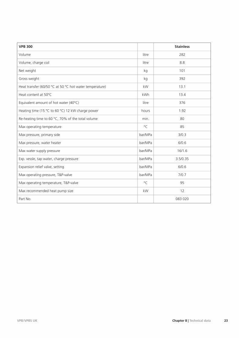
StainlessVPB 300
282litreVolume
8.8litreVolume, charge coil
101kgNet weight
392kgGross weight
13.1kWHeat transfer (60/50 °C at 50 °C hot water temperature)
13.4kWhHeat content at 50°C
376litreEquivalent amount of hot water (40°C)
1.92hoursHeating time (15 °C to 60 °C) 12 kW charge power
80min.Re-heating time to 60 °C, 70% of the total volume
85°CMax operating temperature
3/0.3bar/MPaMax pressure, primary side
6/0.6bar/MPaMax pressure, water heater
16/1.6bar/MPaMax water supply pressure
3.5/0.35bar/MPaExp. vessle, tap water, charge pressure
6/0.6bar/MPaExpansion relief valve, setting
7/0.7bar/MPaMax operating pressure, T&P-valve
95°CMax operating temperature, T&P-valve
12kWMax recommended heat pump size
083 020Part No.
23Chapter 8 | Technical dataVPB/VPBS UK
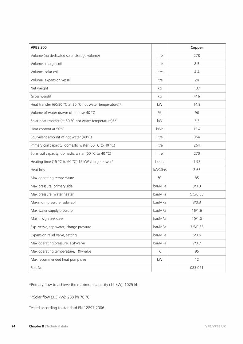
CopperVPBS 300
278litreVolume (no dedicated solar storage volume)
8.5litreVolume, charge coil
4.4litreVolume, solar coil
24litreVolume, expansion vessel
137kgNet weight
416kgGross weight
14.8kWHeat transfer (60/50 °C at 50 °C hot water temperature)*
96%Volume of water drawn off, above 40 °C
3.3kWSolar heat transfer (at 50 °C hot water temperature)**
12.4kWhHeat content at 50°C
354litreEquivalent amount of hot water (40°C)
264litrePrimary coil capacity, domestic water (60 °C to 40 °C)
270litreSolar coil capacity, domestic water (60 °C to 40 °C)
1.92hoursHeating time (15 °C to 60 °C) 12 kW charge power*
2.65kW/24HrsHeat loss
85°CMax operating temperature
3/0.3bar/MPaMax pressure, primary side
5.5/0.55bar/MPaMax pressure, water heater
3/0.3bar/MPaMaximum pressure, solar coil
16/1.6bar/MPaMax water supply pressure
10/1.0bar/MPaMax design pressure
3.5/0.35bar/MPaExp. vessle, tap water, charge pressure
6/0.6bar/MPaExpansion relief valve, setting
7/0.7bar/MPaMax operating pressure, T&P-valve
95°CMax operating temperature, T&P-valve
12kWMax recommended heat pump size
083 021Part No.
*Primary flow to achieve the maximum capacity (12 kW): 1025 l/h
**Solar flow (3.3 kW): 288 l/h 70 °C
Tested according to standard EN 12897:2006.
VPB/VPBS UKChapter 8 | Technical data24
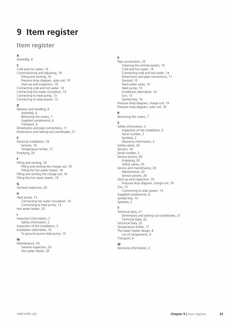
Item registerAAssembly, 6
CCold and hot water, 14Commissioning and adjusting, 18
Filling and venting, 18Pressure drop diagram, solar coil, 19Start-up and inspection, 19
Connecting cold and hot water, 14Connecting hot water circulation, 14Connecting to heat pump, 13Connecting to solar power, 13
DDelivery and handling, 6
Assembly, 6Removing the covers, 7Supplied components, 6Transport, 6
Dimensions and pipe connections, 11Dimensions and setting-out coordinates, 21
EElectrical installation, 16
Sensors, 16Temperature limiter, 17
Emptying, 20
FFilling and venting, 18
Filling and venting the charge coil, 18Filling the hot water heater, 18
Filling and venting the charge coil, 18Filling the hot water heater, 18
GGeneral inspection, 20
HHeat pump, 13
Connecting hot water circulation, 14Connecting to heat pump, 13
Hot water heater, 20
IImportant information, 2
Safety information, 2Inspection of the installation, 5Installation alternative, 14
To ground source heat pump, 15
MMaintenance, 20
General inspection, 20Hot water heater, 20
PPipe connections, 10
Cleaning the climate system, 10Cold and hot water, 14Connecting cold and hot water, 14Dimensions and pipe connections, 11General, 10Hard water areas, 10Heat pump, 13Installation alternative, 14Sun, 13Symbol key, 14
Pressure drop diagram, charge coil, 19Pressure drop diagram, solar coil, 19
RRemoving the covers, 7
SSafety information, 2
Inspection of the installation, 5Serial number, 2Symbols, 2Warranty information, 2
Safety valves, 20Sensors, 16Serial number, 2Service actions, 20
Emptying, 20Safety valves, 20
Service and maintenance, 20Maintenance, 20Service actions, 20
Start-up and inspection, 19Pressure drop diagram, charge coil, 19
Sun, 13Connecting to solar power, 13
Supplied components, 6Symbol key, 14Symbols, 2
TTechnical data, 21
Dimensions and setting-out coordinates, 21Technical Data, 22
Technical Data, 22Temperature limiter, 17The water heater design, 8
List of components, 9Transport, 6
WWarranty information, 2
25Chapter 9 | Item registerVPB/VPBS UK
9 Item register
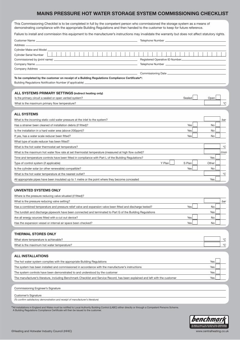
MAINS PRESSURE HOT WATER STORAGE SYSTEM COMMISSIONING CHECKLIST
* llA installations in England and Wales must be notified to Local Authority Building Control (LABC) either directly or through a Competent Persons Scheme. A Building Regulations Compliance Certificate will then be issued to the customer.
©Heating and Hotwater Industry Council (HHIC) www.centralheating.co.uk
ALL SYSTEMS PRIMARY SETTINGS (indirect heating only)
Is the primary circuit a sealed or open vented system? Sealed Open
What is the maximum primary flow temperature? °C
ALL SYSTEMS
What is the incoming static cold water pressure at the inlet to the system? bar
Has a strainer been cleaned of installation debris (if fitted)? Yes No
Is the installation in a hard water area (above 200ppm)? Yes No
If yes, has a water scale reducer been fitted? Yes No
What type of scale reducer has been fitted?
What is the hot water thermostat set temperature? °C
What is the maximum hot water flow rate at set thermostat temperature (measured at high flow outlet)? l/min
Time and temperature controls have been fitted in compliance with Part L of the Building Regulations? Yes
Type of control system (if applicable) Y Plan S Plan Other
Is the cylinder solar (or other renewable) compatible? Yes No
What is the hot water temperature at the nearest outlet? °C
All appropriate pipes have been insulated up to 1 metre or the point where they become concealed Yes
UNVENTED SYSTEMS ONLY
Where is the pressure reducing valve situated (if fitted)?
What is the pressure reducing valve setting? bar
Has a combined temperature and pressure relief valve and expansion valve been fitted and discharge tested? Yes No
The tundish and discharge pipework have been connected and terminated to Part G of the Building Regulations Yes
Are all energy sources fitted with a cut out device? Yes No
Has the expansion vessel or internal air space been checked? Yes No
THERMAL STORES ONLY
What store temperature is achievable? °C
What is the maximum hot water temperature? °C
ALL INSTALLATIONS
The hot water system complies with the appropriate Building Regulations Yes
The system has been installed and commissioned in accordance with the manufacturer’s instructions Yes
The system controls have been demonstrated to and understood by the customer Yes
The manufacturer’s literature, including Benchmark Checklist and Service Record, has been explained and left with the customer Yes
Commissioning Engineer’s Signature
Customer’s Signature
(To confirm satisfactory demonstration and receipt of manufacturer’s literature)
This Commissioning Checklist is to be completed in full by the competent person who commissioned the storage system as a means of
demonstrating compliance with the appropriate Building Regulations and then handed to the customer to keep for future reference.
Failure to install and commission this equipment to the manufacturer’s instructions may invalidate the warranty but does not affect statutory rights.
Customer Name Telephone Number
Address
Cylinder Make and Model
Cylinder Serial Number
Commissioned by (print name) Registered Operative ID Number
Company Name Telephone Number
Company Address
Commissioning Date
To be completed by the customer on receipt of a Building Regulations Compliance Certificate*:
Building Regulations Notification Number (if applicable)
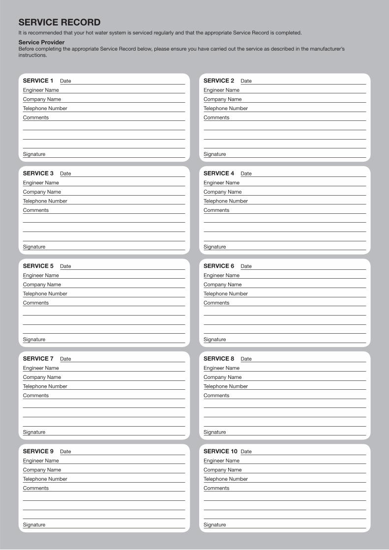
SERVICE RECORDIt is recommended that your hot water system is serviced regularly and that the appropriate Service Record is completed.
Service Provider
Before completing the appropriate Service Record below, please ensure you have carried out the service as described in the manufacturer’s
instructions.
SERVICE 1 Date
Engineer Name
Company Name
Telephone Number
Comments
Signature
SERVICE 2 Date
Engineer Name
Company Name
Telephone Number
Comments
Signature
SERVICE 3 Date
Engineer Name
Company Name
Telephone Number
Comments
Signature
SERVICE 4 Date
Engineer Name
Company Name
Telephone Number
Comments
Signature
SERVICE 5 Date
Engineer Name
Company Name
Telephone Number
Comments
Signature
SERVICE 6 Date
Engineer Name
Company Name
Telephone Number
Comments
Signature
SERVICE 7 Date
Engineer Name
Company Name
Telephone Number
Comments
Signature
SERVICE 8 Date
Engineer Name
Company Name
Telephone Number
Comments
Signature
SERVICE 9 Date
Engineer Name
Company Name
Telephone Number
Comments
Signature
SERVICE 10 Date
Engineer Name
Company Name
Telephone Number
Comments
Signature


NIBE Energy Systems Ltd 3C Broom Business ParkBridge WayChesterfield S41 9QGPhone 0845 095 1200Fax 0845 095 [email protected]
0 3 1 2 9 0