Embed Size (px)
Citation preview

DOOR LOCK TIM
ER
Installer Guide
We Make Things Easy

2
DOOR LOCK TIM
ER
AdapTec is a combination of a power supply and a door controller pack-aged in a compact box to ease on installation, to provide power supply and to enhance access control functionalities.
FUNCTIONS• To power on the time attendance system of FingerTec® terminals.• To link door accessories including EM Lock and Drop Bolt with the Fin-
gerTec® terminals.• To control In-Out reader system; a system where two terminals control
one entrance.• To support rechargeable backup battery (compatible with any 12V re-
chargeable backup battery) and to act as a backup power supply in the event of power failure.
• To integrate with siren feature of the reader to alert user when termi-nals is illegally dismantled.
Note: AdapTec is compatible with NC type of siren with maximum 0.5A load.
SPECIFICATIONSDimension (mm) 198 (L) x 131 (W) x 43 (H)
Weight 920g
Input Voltage AC 110 / 240 V (universal input)
Output Voltage DC 12V 3A
EM Output DC 12V 3A
Siren Output Max 0.5A, NC type

3
INPUT : AC 110 ~ 240VOUTPUT : DC 12V 3A
This is a Door Lock Timer Lengthen timing
Shorten timing
1 2
21
3
1 2
3
THE DESIGNAdapTec consists of 2 main modules and a timer:
1 Power supply/power input module.
2 Access control/power output module.
3 Door lock timer.
POWER SUPPLY/POWER INPUT MODULE 1 This portion is to be connected to
power source with AC110~240V. AC current will be supplied into this side and a DC 12V 3A current will be generated as output.
2 These two cables, -V and +V are default and connected to the in-ner part of AdapTec. Please do not remove or change these cables.
ACCESS CONTROL/POWER OUTPUT MODULE
1 Connect push button here if siren is installed during installation. A press on the push button will turn off siren when the siren is trig-gered.
2 AdapTec may have broken and needs to be repaired.
3 These are the power outputs from AdapTec. Refer to the wiring dia-grams in page 3, for details.
DOOR LOCK TIMER
User can adjust the timing for the EM Lock and Drop Bolt to close after opening using door lock timer. Turn the timer using a screwdriver, turning clockwise will lengthen the time, turn-ing anti-clockwise will shorten the time.
Note: AdapTec can be connected to other devices, which are having the same power consump-tion. Please seek FingerTec®’s advice through [email protected] before using AdapTec with other FingerTec® models.
4
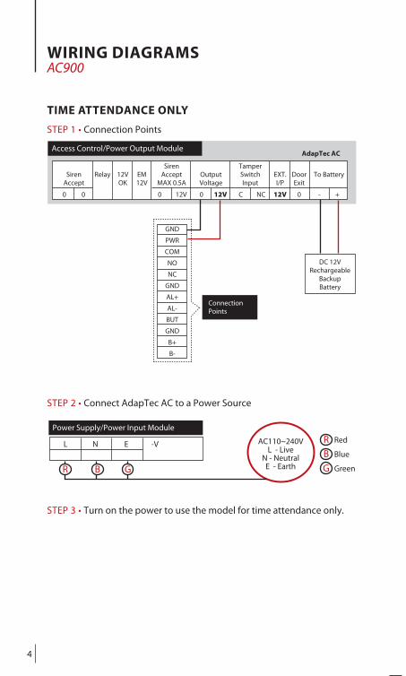
L N E -V
Power Supply/Power Input Module
AC110~240VL - Live
N - NeutralE - EarthR B G
R Red
B Blue
G Green
AdapTec ACAccess Control/Power Output Module
Siren Tamper Siren Relay 12V EM Accept Output Switch EXT. Door To Battery Accept OK 12V MAX 0.5A Voltage Input I/P Exit
0 0 0 12V 0 12V C NC 12V 0 - +
Connection Points
GND
PWR
COM
NO
NC
GND
AL+
AL-
BUT
GND
B+
B-
DC 12VRechargeable
Backup Battery
WIRING DIAGRAMS AC900
TIME ATTENDANCE ONLY
STEP 1 • Connection Points
STEP 2 • Connect AdapTec AC to a Power Source
STEP 3 • Turn on the power to use the model for time attendance only.

5
AdapTec ACAccess Control/Power Output Module
Siren Tamper Siren Relay 12V EM Accept Output Switch EXT. Door To Battery Accept OK 12V MAX 0.5A Voltage Input I/P Exit
0 0 0 12V 0 12V C NC 12V 0 - +
GND
PWR
COM
NO
NC
GND
AL+
AL-
BUT
GND
B+
B-
DC 12VRechargeable
Backup Battery
L N E -V +V
Power Supply/Power Input Module
EM +
Lock -
Emergency 2 Break Glass (NC) 3
ON-OFF C Key Switch (NC) D
PushButton
AC110~240VL - Live
N - NeutralE - EarthR B G
R Red
B Blue
G Green
Connection Points
WIRING DIAGRAMS AC900
ACCESS CONTROL ONLY OR TIME ATTENDANCE & DOOR ACCESS
STEP 1 • Connection Points
STEP 2 • Connect AdapTec AC to a Power Source
STEP 3 • Turn on the power to use the AC900 for door access control only or for time attendance and door access control simultaneously
6
R Red
B Blue
G Green
AdapTec ACAccess Control/Power Output Module
Siren Tamper Siren Relay 12V EM Accept Output Switch EXT. Door To Battery Accept OK 12V MAX 0.5A Voltage Input I/P Exit
0 0 0 12V 0 12V C NC 12V 0 - +
NC2
COM2
NO2
NC1
COM1
NO1
BUT
GND
SEN
485B
485A
GND
232T
232R
GND
WD1
WD0
RJ45-1
RJ45-2
RJ45-3
RJ45-6
BELL+
BELL-
BEEP
GLED
RLED
INWD0
INWD1
GND
+12V
L N E -V +V
Power Supply/Power Input Module
AC110~240VL - Live
N - NeutralE - EarthR B G
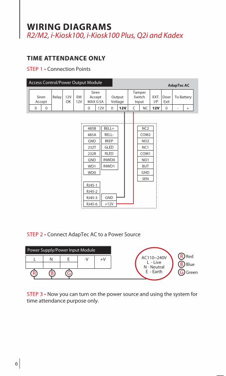
WIRING DIAGRAMS R2/M2, i-Kiosk100, i-Kiosk100 Plus, Q2i and Kadex
TIME ATTENDANCE ONLY
STEP 1 • Connection Points
STEP 2 • Connect AdapTec AC to a Power Source
STEP 3 • Now you can turn on the power source and using the system for time attendance purpose only.

7
AdapTec ACAccess Control/Power Output Module
Siren Tamper Siren Relay 12V EM Accept Output Switch EXT. Door To Battery Accept OK 12V MAX 0.5A Voltage Input I/P Exit
0 0 0 12V 0 12V C NC 12V 0 - +
R Red
B Blue
G Green
L N E -V +V
Power Supply/Power Input Module
AC110~240VL - Live
N - NeutralE - Earth
NC2
COM2
NO2
NC1
COM1
NO1
BUT
GND
SEN
EM +
Lock -
Emergency 2 Break Glass (NC) 3
ON-OFF C Key Switch (NC) D
Release Button
485B
485A
GND
232T
232R
GND
WD1
WD0
RJ45-1
RJ45-2
RJ45-3
RJ45-6
BELL+
BELL-
BEEP
GLED
RLED
INWD0
INWD1
GND
+12V
R B G
WIRING DIAGRAMS R2/M2, i-Kiosk100, i-Kiosk100 Plus, Q2i and Kadex
ACCESS CONTROL ONLY OR TIME ATTENDANCE & DOOR ACCESS
STEP 1 • Connection Points
STEP 2 • Connect AdapTec AC to a Power Source
STEP 3 • Turn on the power to use the model for door access control only or for time attendance and door access control simultaneously.

8
AdapTec ACAccess Control/Power Output Module
Siren Tamper Siren Relay 12V EM Accept Output Switch EXT. Door To Battery Accept OK 12V MAX 0.5A Voltage Input I/P Exit
0 0 0 12V 0 12V C NC 12V 0 - +
L N E -V +V
Power Supply/Power Input Module
AC110~240VL - Live
N - NeutralE - EarthR B G
EM +
Lock -
Emergency 2 Break Glass (NC) 3
ON-OFF C Key Switch (NC) D
Release Button
NO
2
COM
2
NC
2
SEN
GN
D
BUT
NO
1
COM
1
NC
1
485-
485+
GN
D
TXD
RXD
WD
0
WD
1
SGN
D
GN
D
+12V
Connection Points in FingerTec® Face ID2
R Red
B Blue
G Green
WIRING DIAGRAMS Face ID 2
ACCESS CONTROL ONLY OR TIME ATTENDANCE & DOOR ACCESS
STEP 1 • Connection points
STEP 2 • Connect AdapTec AC to a power source
STEP 3 • Turn on the power to use FingerTec® Face ID 2 for door access control only or for time attendance and door access control simultane-ously.

9
AdapTec ACAccess Control/Power Output Module
Siren Tamper Siren Relay 12V EM Accept Output Switch EXT. Door To Battery Accept OK 12V MAX 0.5A Voltage Input I/P Exit
0 0 0 12V 0 12V C NC 12V 0 - +
L N E -V +V
Power Supply/Power Input Module
AC110~240VL - Live
N - NeutralE - EarthR B G
NO
2
COM
2
NC
2
SEN
GN
D
BUT
NO
1
COM
1
NC
1
485-
485+
GN
D
TXD
RXD
WD
0
WD
1
SGN
D
GN
D
+12V
DC 12VRechargeable
Backup Battery
R Red
B Blue
G Green
Connection Points in FingerTec® Face ID2
WIRING DIAGRAMS Face ID 2
TIME ATTENDANCE ONLY
STEP 1 • Connection points
STEP 2 • Connect AdapTec AC to a power source
STEP 3 • Turn on the power to use FingerTec® Face ID 2 for time attend-ance.

10
BEEP
GLED
RLED
INWD0
INWD1
GND
+12V
Siren EM Siren Output Output Tamper EXT. Door To Accept 12V MAX 0.6A Voltage Switch Input I/P Exit Battery 0 0 0 12 0 12V C NC 12V 0 -- +
RJ45-1
RJ45-2
RJ45-3
RJ45-6
WD0
WD1
GND
RXD
TXD
GND
485+
485-
ALM+
ALM-
NC
COM
NO
BUT
GND
SEN
BEL+
BEL-
GND
+12V
Push button - +
Alarm Siren
Access Control/Power Output Module
AN ALARM SIREN TO SECURE YOUR FINGERTEC® TERMINAL
For all FingerTec® door access control models, there is a security spring behind the terminal. During normal operation, the security spring is compressed and once the reader is dismantled, the spring will be released and “System broken” message will appear onscreen. During the release of the spring, the reader is out-putting alarm signal. Nonetheless, no alarm sound is emitted because the reader is not equipped with pre-installed siren.
To use the siren feature, we recommend you to install an additional alarm siren and connect it to FingerTec® terminals.
BENEFITS OF USING ADAPTEC AC WITH ALARM SIRENWe recommend you to install terminal using AdapTec AC if you plan to use alarm siren. In AdapTec AC, an additional port is readily built to receive alarm signal from FingerTec® terminals. AdapTec AC is outputting DC12V and it is suitable to use with alarm siren that is having the same power input. You do not need to source additional DC12V power supply for this purpose. Furthermore, AdapTec AC provides a “Siren Accept” button where you can press the button to deactivate alarm siren when required.
FUNCTION • R2/M2, i-Kiosk100, i-Kiosk100 Plus ,Q2i and KadexConnect the terminal, alarm siren and AdapTec AC as below. Kindly set the jumper at the back of the terminal to support alarm signal type NC.
STEP 1 • Wiring Diagram

11
Siren EM Siren Output Output Tamper EXT. Door To Accept 12V MAX 0.6A Voltage Switch Input I/P Exit Battery 0 0 0 12 0 12V C NC 12V 0 -- +
Access Control/Power Output Module
GND
PWR
COM
NO
NC
GND
AL+
AL-
BUT
GND
B+
B-
Push button
+ -
Alarm Siren
GND
RX
TX
GND
485A
485B
GND
D0
D1
+5V
SEN
GND
Access Control/Power Output Module
Siren Tamper Siren Relay 12V EM Accept Output Switch EXT. Door To Battery Accept OK 12V MAX 0.5A Voltage Input I/P Exit
0 0 0 12V 0 12V C NC 12V 0 - +
NO
2
COM
2
NC
2
SEN
GN
D
BUT
NO
1
COM
1
NC
1
485-
485+
GN
D
TXD
RXD
WD
0
WD
1
SGN
D
GN
D
+12V
Push Button Alarm Siren
FUNCTION • AC900For AC900, you will need to connect AC900, alarm siren and AdapTec AC as below.
FUNCTION • Face ID 2For Face ID 2, you will need to connect to alarm siren and AdapTec AC as below.
Reminder to deactivate alarm siren:1. You can deactivate the alarm siren by pressing push button that is connected to Siren
Accept in AdapTec AC. This action will turn off the alarm siren function in AdapTec AC. However, you must restart AdapTec AC to turn on alarm siren function again. The alarm siren will not take effect in the future if you do not restart the AdapTec AC.
2. You can do it from the terminal via Menu > Turn Off Alarm to turn off the alarm siren. You do not need to restart the AdapTec AC. The alarm siren will return to standby mode after you do the steps at the reader. (Recommended)

12
WALLWALL
WOODEN DOOR
OUTDOOR
4 feet / 1.2 meter(recommended)
1
Screws
Back SteelPlate
2
CEILING
INDOOR
SilverNut
SteelBar
Allen KeyScrew
Wooden Doorframe
CEILING
INDOOR
Screws
Magnet
Doorframe
AluminumPlate
AllenKey
Screws
3
1
2
2
1
23
1
2
3
INSTALLATION • Wooden Door
1 To install FingerTec® AC900/M2/R2 on a wall, drill 5 holes as shown. 4 small holes are for the screws and the bigger hole is for the network cable.
2 Tighten the 4 screws to fix the Back Plate on the wall.
3 Install the keyswitch as per instructions given in the box. The keyswitch is an override key in case of system failure or break-down.
1 Drill 3 holes on the wooden door.
2 Place Steel Bar on the door. Insert the Silver Nut on one side and Al-len Key Screw on the other side. Tighten the screw to lock the Steel Bar onto its position.
1 Drill 4 holes on the wooden frame. Tighten the 4 screws to fix the Aluminum Plate prop-erly on the doorframe.
2 Use Allen Key to tighten the 2 screws at the bot-tom of the Magnet. The Magnet will stick to the Aluminum Plate when the screws are tight-ened .
3 Use Allen Key to tighten the other 2 screws on the sides of the Magnet.

13
EmergencyBreak Glass
Push Button
CEILING
ABOVE CEILING
Hub / Switch
PC
OUTDOOR INDOOR NETWORKING
FingerTec®Series
AdapTec AC
ON-OFF Keyswitch
To FingerTec® Series
AC110/240VPowerInput
12V Rechargeable battery
CEILING
ABOVE CEILING
BELOWCEILING
Computer/ Network Hub/
Network Switch
2
To FingerTec®Series
3
AC110/240VPowerInput
1 1
2
3
4 feet / 1.2 meter(recommended)
CEILING
INDOOR
EmergencyBreak Glass
Push Button
4
5
6
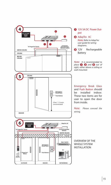
1 12V 3A DC Power Out-put
2 AdapTec AC Note: Refer to AdapTec user
guide for wiring diagrams.
3 12V Rechargeable Bat-tery
Note: It is recommended to place 1 , 2 and 3 out of sight, either above a ceiling or wall-mounted.
Emergency Break Glass and Push Button should be installed indoor. These two items are for user to open the door from inside.
Note: Please conceal the wir-ing.
OVERVIEW OF THE
WHOLE SYSTEM
INSTALLATION
14
CEILING
CEILING
INDOOR
Screws
Magnet
Doorframe
AluminumPlate
AllenKey
Screws
1
23
GLASS DOOR
WALLWALL
OUTDOOR
4 feet / 1.2 meter(recommended)
Screws
Back SteelPlate
1
2
3
OUTDOOR
U-Bracket
Philip Screw
SteelBar
Allen KeyScrews
Allen KeyScrews
Glass Doorframe
1
12
1
2
3
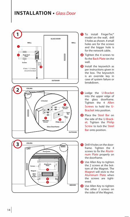
INSTALLATION • Glass Door
1 To install FingerTec® model on the wall, drill 5 holes as shown. 4 small holes are for the screws and the bigger hole is for the network cable.
2 Tighten the 4 screws to fix the Back Plate on the wall.
3 Install the keyswitch as per instructions given in the box. The keyswitch is an override key in case of system failure or breakdown.
1 Lodge the U-Bracket into the upper edge of the glass doorframe. Tighten the 4 Allen Screws to hold the U-Bracket into position.
2 Place the Steel Bar on the side of the U-Brack-et. Tighten the Philip Screw to lock the Steel Bar onto position.
1 Drill 4 holes on the door-frame. Tighten the 4 screws to fix the Alumi-num Plate properly on the doorframe.
2 Use Allen Key to tighten the 2 screws at the bot-tom of the Magnet. The Magnet will stick to the Aluminum Plate when the screws are tight-ened.
3 Use Allen Key to tighten the other 2 screws on the sides of the Magnet.
15
CEILING
ABOVE CEILING
BELOWCEILING
Computer/ Network Hub/
Network Switch
2
To FingerTec®Series
3
AC110/240VPowerInput
1 1
2
3
4 feet / 1.2 meter(recommended)
CEILING
EmergencyBreak Glass
Push Button
INDOOR
EmergencyBreak Glass
Push Button
CEILING
ABOVE CEILING
Hub / Switch
PC
OUTDOOR INDOOR NETWORKING
FingerTec®Series
AdapTec AC
ON-OFF Keyswitch
To FingerTec® Series 12V Rechargeable battery
AC110/240VPowerInput
4
5
6
1 12V 3A DC Power Out-put
2 AdapTec AC Note: Refer to AdapTec user guide for wiring diagrams.
3 12V Rechargeable Battery
Note: It is recommended to place 1 , 2 and 3 out of sight, either above a ceiling or wall-mounted.
Emergency Break Glass and Push Button should be installed indoor. These two items are for user to open the door from inside.
Note: Please conceal the wiring.
OVERVIEW OF THEWHOLE SYSTEM INSTALLATION

INSTALLATION How to mount an AdapTec AC onto a wall
1
2
4
INPUT : AC 110 ~ 240VOUTPUT : DC 12V 3A
After removing the piece, you will have one L-shape piece and 2 screws.
3
Identify a location to mount the AdapTec AC on a wall.
Fix the AdapTec AC onto the wall by tightening the screws into the 4 holes.
Remove the L-shape piece from the AdapTec AC
Find an L-shape piece at the top right of an AdapTec AC. This piece is attached to the AdapTec AC by 2 screws.
Attach the L-shape to the AdapTec AC as shown and tighten the screws.
Open the cap, look for the part shown in the diagram and you will see 2 holes.
www.fingertec.com© 2010 FingerTec Worldwide Sdn. Bhd. All rights reserved. • Printed in Malaysia. 042010
Install the piece to the AdapTec AC The other 2 holes at the bottom
Mount the AdapTec AC on a wall