Embed Size (px)
Citation preview
Low Voltage Electricity & WaterCS-CSI-P1/C5
Ins ta l la t ions Regu la t ions
DISTRICT COOLING Design & Water Management Code 2016

His HighnessSheikh Tameem Bin Hamad Al-Thani
Emir of the State of Qatar

DC Design & Water Management Code
2016
DC
DE
SIG
N &
WATE
R M
AN
AG
EM
EN
T CO
DE
Issue : 0 16-10-2016 Unclassified
Page 03 of 44
DC Design & Water Management Code CS-CSI-P1/C5
PREFACE:
The ultimate goals of the technical documents of the District Cooling (DC) Regulations of the State of Qatar can be summarized as follows:
1. Human health and environmental safety2. Reliability3. Efficient use of water4. Efficient use of energy5. Sustainability6. Cost-effectiveness
DC Regulations includes two parts.
Part 1
District Cooling Design and Water Management Standards, which are mandatory, minimum requirements for the design of DC Systems that are deemed essential for meeting the KPIs.
Part 2
District Cooling Services Key Performance Indicators (KPIs), which are mandatory, minimum requirements for the performance of DC Systems.
DC
DE
SIG
N &
WAT
ER
MA
NA
GE
ME
NT
CO
DE
Issue : 0 16-10-2016 Unclassified
Page 04 of 44
DC Design & Water Management Code CS-CSI-P1/C5
CONTENT
Part 1. District Cooling
1. Definitions & Abbreviations1.1 Definitions1.2 Abbreviations2. District Cooling Design & Water Management Standards2.1 General
2.1.1 Purpose
2.1.2 Exemptions
2.1.3 Laws and Regulations
2.2 District Cooling System2.2.1 General Requirements
2.2.2 Human Health and Environmental Safety
2.2.3 DC Plant
2.2.4 Water Management
2.2.5 Distribution Pipelines
2.2.6 Building Connection
2.2.7 Commissioning
List of TablesTable 1: Quarterly Water Quality Reports
Table 2: Metering Equipment Accuracy Requirements
Part 2. Key Performance Indicators (KPIs)
1. Key Performance Indicators (KPIs) .1.1 Compliance Requirement 1.2 Compliance Reporting
1.2.1 DC Providers
1.2.2 DC Retailers
1.2.3 Consequences of Non-Compliance
1.2.4 Other Laws, Standards, Regulations and Codes
1.3 Reliability 1.4 Energy Efficiency 1.5 Water Management
1.5.1 Water Consumption for Cooling Tower Makeup
1.5.2 Wastewater Discharge Quantity
06
060615161616
16
16
1717
18
19
22
26
27
30
25
30
31
31313131
32
32
33
33343535
36
CONTENT
DC
DE
SIG
N &
WATE
R M
AN
AG
EM
EN
T CO
DE
Issue : 0 16-10-2016 Unclassified
Page 05 of 44
DC Design & Water Management Code CS-CSI-P1/C5
37
37
383939
39
41
42
43
43
4343
43
44
44
44
31
34
34
35
35
36
37
37
37
38
1.5.3 Water Consumption for Chilled Water Makeup
1.5.4 Quality of Circulating Water in Cooling Tower
1.6 Energy Metering 1.7 DC Provider Annual Information Returns
General Information
DC Provider Key Performance Indicator Data
DC Provider Additional Data for Each DC System
DC Provider Additional Data for Each DC Plant
Maintenance Logs (attachments)
Statements of Compliance (attachments)
1.8 DC Retailer Annual Information Returns General Information
DC Retailer Key Performance Indicator Data
DC Retailer Additional Data
Maintenance Logs (attachments)
Statements of Compliance (attachments)
List of Tables Table 0: Overview of Key Performance Indicators
Table 1: KPI 1 -- System Reliability
Table 2: KPI 2 -- Electricity Consumption in New Plants
Table 3: KPI 3 -- Electricity Consumption in Existing DC Plants
Table 4: KPI 4 -- Electricity Consumption in Temporary Plants
Table 5: KPI 5 -- Water Consumption for Condenser Cooling
Table 6: KPI 6 – Quantity of Wastewater Discharge
Table 7: KPI 7 -- Water Consumption for Chilled Water Makeup
Table 8: KPI 8 – Cooling Tower Circulating Water Quality
Table 9: KPI 9 -- Bulk-Metering Equipment and Sub-Metering Equipment
Service Intervals
DC
DE
SIG
N &
WAT
ER
MA
NA
GE
ME
NT
CO
DE
Issue : 0 16-10-2016 Unclassified
Page 06 of 44
DC Design & Water Management Code CS-CSI-P1/C5
District Cooling Design and Water Management Standards1. Definitions & Abbreviations
In this document, except where the context otherwise requires, words and phrases shall have the meanings, and use the abbreviations, set forth herein.
1.1 Definitions
Term Definition
Air conditioning The process of treating air to simultaneously control its temperature, humidity and cleanliness, and distribution of this air to meet the requirements of the conditioned space.
Annual Information Return A report required to be submitted by DC Providers or DC Retailers containing specified information.
Blowdown Water The effluent water which is released from a water-cooled Cooling Tower system to maintain the concentration of Total Dissolved Solids at an acceptable level.
Building Buildings and associated structures and facilities constructed or to be constructed by, or on behalf of, Customers.
Building Side The Building System side at the Point of Delivery. Also sometimes referred to as Secondary Side.
Building System A Chilled Water system and associated equipment within a Building.
Bulk-Metering Equipment Any apparatus owned, operated and maintained by the DC Provider used in or in connection with DC Provider Facilities for the purpose of determining the Cooling Energy and Cooling Load of a DC Retailer, Building or a group of Buildings.
Bulk-Service ETS Equipment A facility used to transfer Cooling Energy from DC Provider Facilities to DC Retailer Facilities, which will include:
a. In the case of a Direct Connection, pipes, valves, sensors, instrumentation, controls and Bulk-Metering Equipment; and
b. In the case of an Indirect Connection, Heat Exchanger(s), pipes, valves, sensors, instrumentation, controls and Bulk-Metering Equipment.
Charging In the context of TES, means storing Cooling Energy by removing heat from a TES facility.
Chilled Water Cool water used in a closed hydronic system (typically chemically treated) for Air Conditioning or process cooling applications.
DC
DE
SIG
N &
WATE
R M
AN
AG
EM
EN
T CO
DE
Issue : 0 16-10-2016 Unclassified
Page 07 of 44
DC Design & Water Management Code CS-CSI-P1/C5
Chilled Water Return Chilled Water which has a flow direction toward a DC Plant (in a DC Network) or toward ETS Equipment (in a Building System).
Chilled Water Supply Chilled Water which has a flow direction toward a Building (in a DC Network) or toward Air Conditioning units (in a Building System).
Coincident Peak Load The sum of Cooling Loads for all Customers at the time of the DC System Peak Cooling Load.
Cooling Energy Removal of heat energy, expressed in Ton-hours of Refrigeration.
Cooling Load The rate of removal of heat energy, expressed in Tons of Refrigeration.
Cooling Load Diversity Factor The sum of Cooling Loads for all Customers at the time of the DC System Peak Cooling Load (“Coincident Peak Load”) divided by the sum of all individual Customer Peak Cooling Loads regardless of when those individual Peak Cooling Loads occurred (“Non-coincident Peak Load”).
Cooling Tower A heat removal device using water to reject heat to the atmosphere and cool the condenser side of a chiller. Cooling Towers use evaporation (latent heat of vaporization) to reject heat from condenser water.
Condenser Cooling Plan A plan provided by the DC Provider showing potential condenser cooling alternatives and to be approved by the District Cooling Service Department Kaharamaa.
Customer A person or entity that includes, but is not limited to, an owner of a Building or an apartment, home unit or other form of segregated accommodation within a Building, or an owners’ association in relation to a Building, or an industrial facility, who contracts with a DC Retailer for DC Retailer Services.
DC Network The reticulation network (including all pipes, gaskets, pumps, valves and connectors) and related equipment to be operated and maintained by the DC Provider for purposes of transporting Chilled Water from one or more DC Plant(s) or Temporary Plant(s) to Building(s) or to Distribution Pipelines that comprise a portion of DC Retailer Facilities.
DC Plant The plant, including pumping stations, chillers, TES facilities, Cooling Towers, associated electrical substations, Emergency power supply equipment, systems control, switchgear, electrical installation auxiliary equipment, piping and other installations and ancillary equipment, used or useful in the production of Cooling Energy and the distribution of Chilled Water, operated and maintained for purposes of supporting the provision of DC Provider Services, to be installed on a DC Plot.
DC
DE
SIG
N &
WAT
ER
MA
NA
GE
ME
NT
CO
DE
Issue : 0 16-10-2016 Unclassified
Page 08 of 44
DC Design & Water Management Code CS-CSI-P1/C5
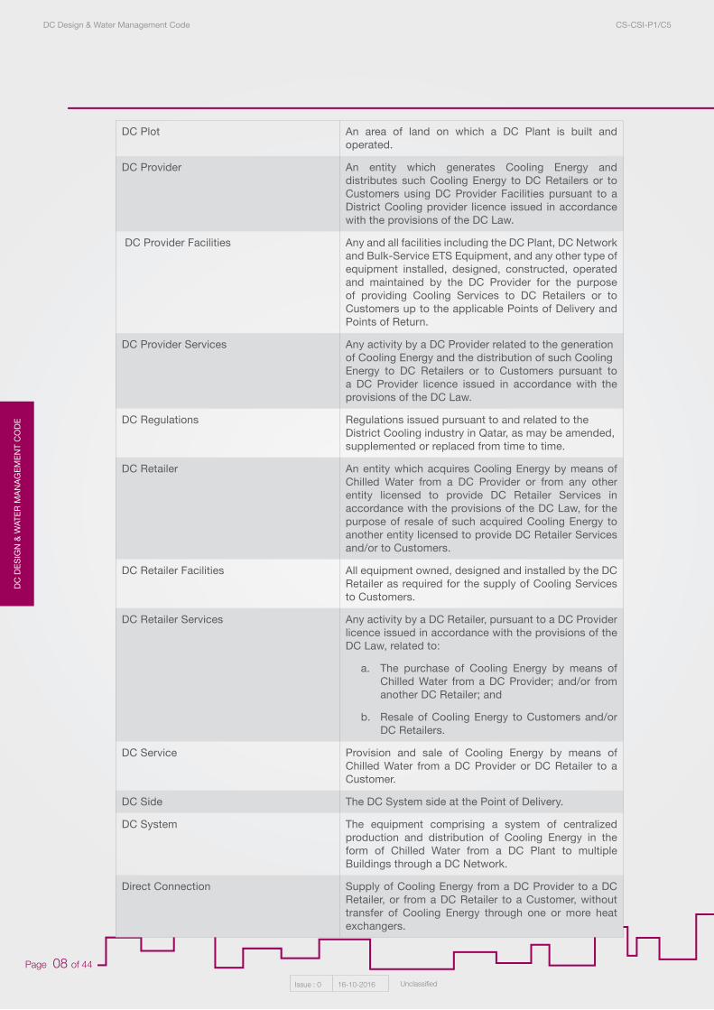
DC Plot An area of land on which a DC Plant is built and operated.
DC Provider An entity which generates Cooling Energy and distributes such Cooling Energy to DC Retailers or to Customers using DC Provider Facilities pursuant to a District Cooling provider licence issued in accordance with the provisions of the DC Law.
DC Provider Facilities Any and all facilities including the DC Plant, DC Network and Bulk-Service ETS Equipment, and any other type of equipment installed, designed, constructed, operated and maintained by the DC Provider for the purpose of providing Cooling Services to DC Retailers or to Customers up to the applicable Points of Delivery and Points of Return.
DC Provider Services Any activity by a DC Provider related to the generationof Cooling Energy and the distribution of such CoolingEnergy to DC Retailers or to Customers pursuant to a DC Provider licence issued in accordance with the provisions of the DC Law.
DC Regulations Regulations issued pursuant to and related to theDistrict Cooling industry in Qatar, as may be amended,supplemented or replaced from time to time.
DC Retailer An entity which acquires Cooling Energy by means of Chilled Water from a DC Provider or from any other entity licensed to provide DC Retailer Services in accordance with the provisions of the DC Law, for the purpose of resale of such acquired Cooling Energy to another entity licensed to provide DC Retailer Services and/or to Customers.
DC Retailer Facilities All equipment owned, designed and installed by the DC Retailer as required for the supply of Cooling Services to Customers.
DC Retailer Services Any activity by a DC Retailer, pursuant to a DC Provider licence issued in accordance with the provisions of the DC Law, related to:
a. The purchase of Cooling Energy by means of Chilled Water from a DC Provider; and/or from another DC Retailer; and
b. Resale of Cooling Energy to Customers and/or DC Retailers.
DC Service Provision and sale of Cooling Energy by means of Chilled Water from a DC Provider or DC Retailer to a Customer.
DC Side The DC System side at the Point of Delivery.
DC System The equipment comprising a system of centralized production and distribution of Cooling Energy in the form of Chilled Water from a DC Plant to multiple Buildings through a DC Network.
Direct Connection Supply of Cooling Energy from a DC Provider to a DC Retailer, or from a DC Retailer to a Customer, without transfer of Cooling Energy through one or more heat exchangers.
DC
DE
SIG
N &
WATE
R M
AN
AG
EM
EN
T CO
DE
Issue : 0 16-10-2016 Unclassified
Page 09 of 44
DC Design & Water Management Code CS-CSI-P1/C5
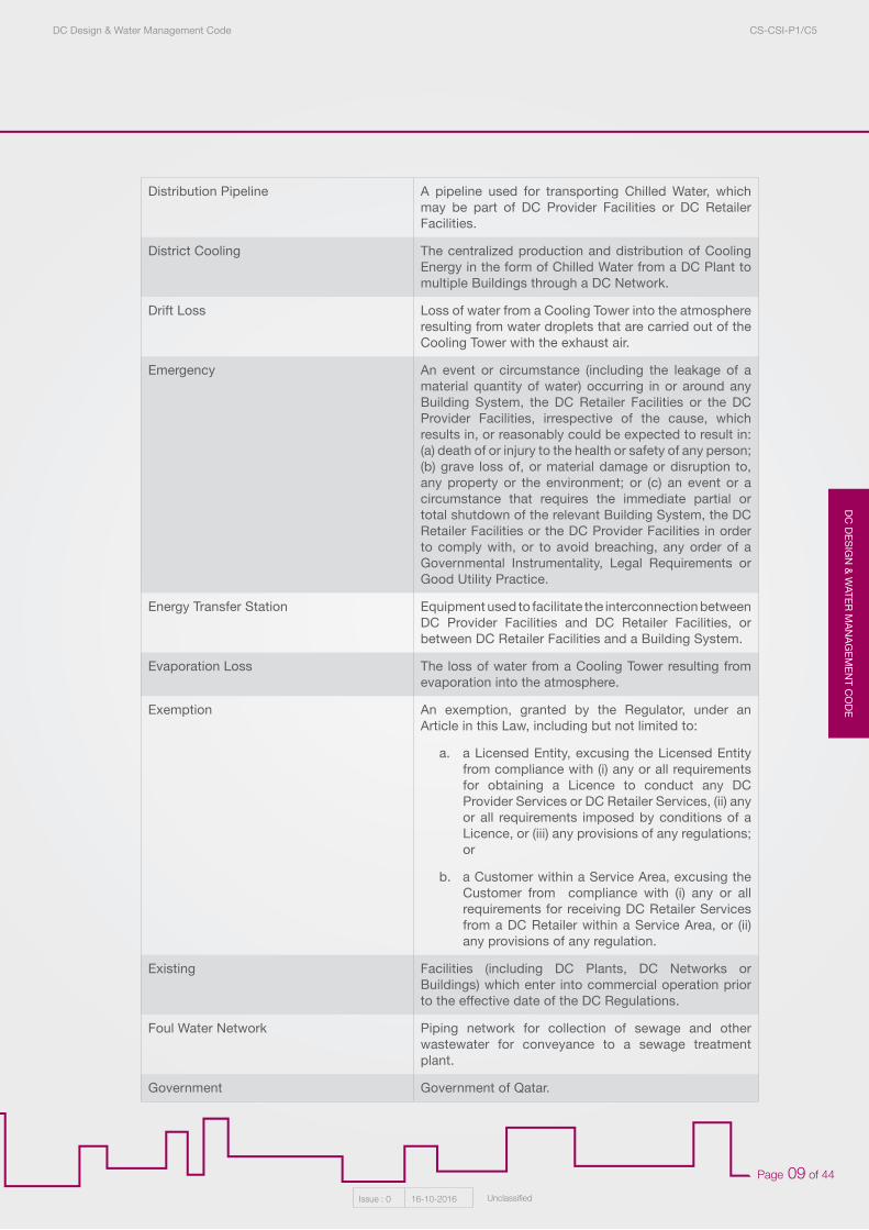
Distribution Pipeline A pipeline used for transporting Chilled Water, which may be part of DC Provider Facilities or DC Retailer Facilities.
District Cooling The centralized production and distribution of Cooling Energy in the form of Chilled Water from a DC Plant to multiple Buildings through a DC Network.
Drift Loss Loss of water from a Cooling Tower into the atmosphere resulting from water droplets that are carried out of the Cooling Tower with the exhaust air.
Emergency An event or circumstance (including the leakage of a material quantity of water) occurring in or around any Building System, the DC Retailer Facilities or the DC Provider Facilities, irrespective of the cause, which results in, or reasonably could be expected to result in: (a) death of or injury to the health or safety of any person; (b) grave loss of, or material damage or disruption to, any property or the environment; or (c) an event or a circumstance that requires the immediate partial or total shutdown of the relevant Building System, the DC Retailer Facilities or the DC Provider Facilities in order to comply with, or to avoid breaching, any order of a Governmental Instrumentality, Legal Requirements or Good Utility Practice.
Energy Transfer Station Equipment used to facilitate the interconnection between DC Provider Facilities and DC Retailer Facilities, or between DC Retailer Facilities and a Building System.
Evaporation Loss The loss of water from a Cooling Tower resulting from evaporation into the atmosphere.
Exemption An exemption, granted by the Regulator, under an Article in this Law, including but not limited to:
a. a Licensed Entity, excusing the Licensed Entity from compliance with (i) any or all requirements for obtaining a Licence to conduct any DC Provider Services or DC Retailer Services, (ii) any or all requirements imposed by conditions of a Licence, or (iii) any provisions of any regulations; or
b. a Customer within a Service Area, excusing the Customer from compliance with (i) any or all requirements for receiving DC Retailer Services from a DC Retailer within a Service Area, or (ii) any provisions of any regulation.
Existing Facilities (including DC Plants, DC Networks or Buildings) which enter into commercial operation prior to the effective date of the DC Regulations.
Foul Water Network Piping network for collection of sewage and other wastewater for conveyance to a sewage treatment plant.
Government Government of Qatar.
DC
DE
SIG
N &
WAT
ER
MA
NA
GE
ME
NT
CO
DE
DC Design & Water Management Code CS-CSI-P1/C5
Issue : 0 16-10-2016 Unclassified
Page 10 of 44
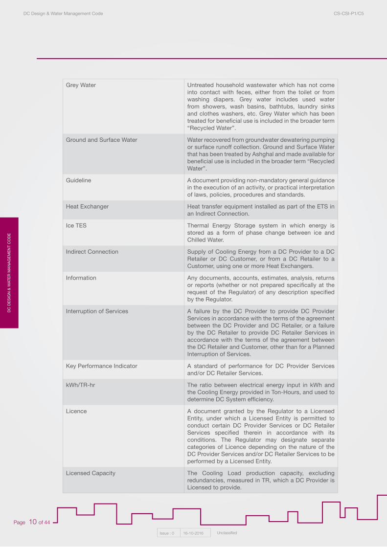
Grey Water Untreated household wastewater which has not come into contact with feces, either from the toilet or from washing diapers. Grey water includes used water from showers, wash basins, bathtubs, laundry sinks and clothes washers, etc. Grey Water which has been treated for beneficial use is included in the broader term “Recycled Water”.
Ground and Surface Water Water recovered from groundwater dewatering pumping or surface runoff collection. Ground and Surface Water that has been treated by Ashghal and made available for beneficial use is included in the broader term “Recycled Water”.
Guideline A document providing non-mandatory general guidance in the execution of an activity, or practical interpretation of laws, policies, procedures and standards.
Heat Exchanger Heat transfer equipment installed as part of the ETS in an Indirect Connection.
Ice TES Thermal Energy Storage system in which energy is stored as a form of phase change between ice and Chilled Water.
Indirect Connection Supply of Cooling Energy from a DC Provider to a DC Retailer or DC Customer, or from a DC Retailer to a Customer, using one or more Heat Exchangers.
Information Any documents, accounts, estimates, analysis, returns or reports (whether or not prepared specifically at the request of the Regulator) of any description specified by the Regulator.
Interruption of Services A failure by the DC Provider to provide DC Provider Services in accordance with the terms of the agreement between the DC Provider and DC Retailer, or a failure by the DC Retailer to provide DC Retailer Services in accordance with the terms of the agreement between the DC Retailer and Customer, other than for a Planned Interruption of Services.
Key Performance Indicator A standard of performance for DC Provider Services and/or DC Retailer Services.
kWh/TR-hr The ratio between electrical energy input in kWh and the Cooling Energy provided in Ton-Hours, and used to determine DC System efficiency.
Licence A document granted by the Regulator to a Licensed Entity, under which a Licensed Entity is permitted to conduct certain DC Provider Services or DC Retailer Services specified therein in accordance with its conditions. The Regulator may designate separate categories of Licence depending on the nature of the DC Provider Services and/or DC Retailer Services to be performed by a Licensed Entity.
Licensed Capacity The Cooling Load production capacity, excluding redundancies, measured in TR, which a DC Provider is Licensed to provide.
DC
DE
SIG
N &
WATE
R M
AN
AG
EM
EN
T CO
DE
DC Design & Water Management Code CS-CSI-P1/C5
Issue : 0 16-10-2016 Unclassified
Page 11 of 44
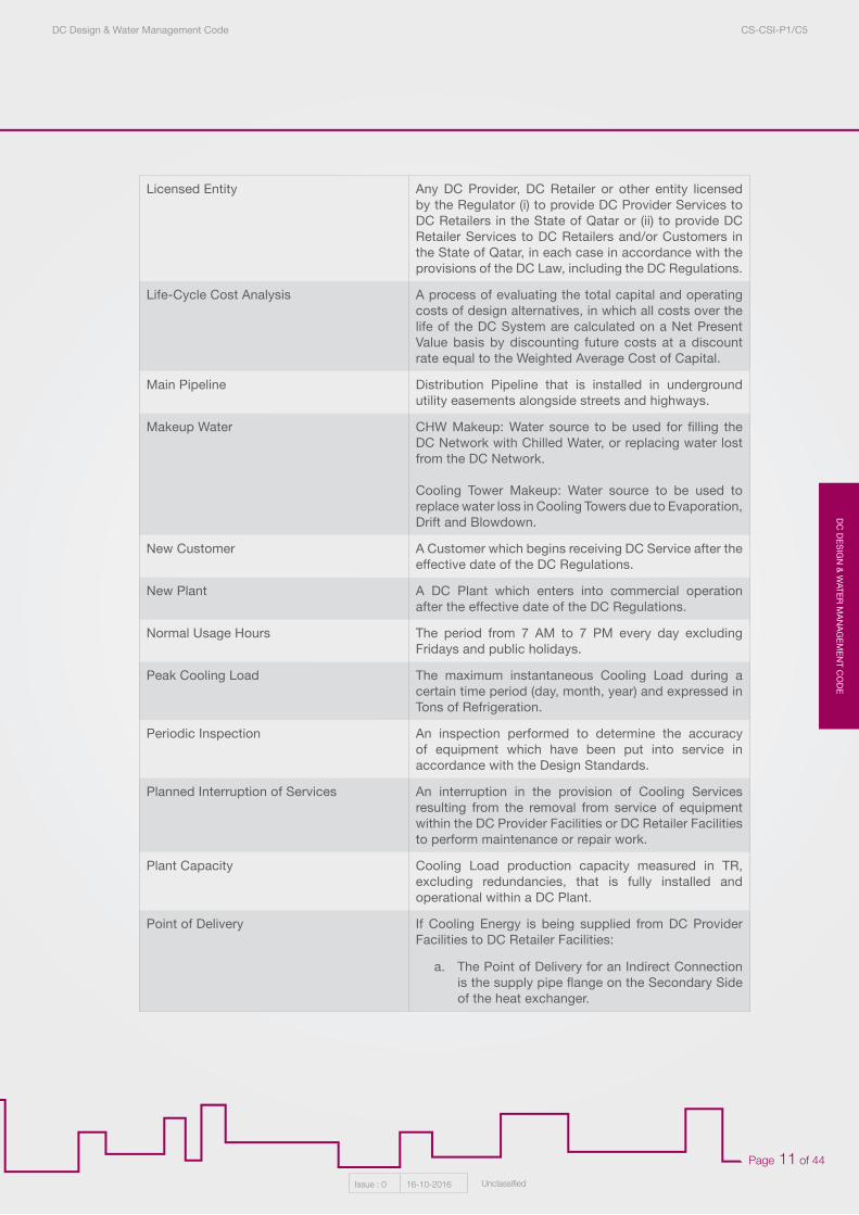
Licensed Entity Any DC Provider, DC Retailer or other entity licensed by the Regulator (i) to provide DC Provider Services to DC Retailers in the State of Qatar or (ii) to provide DC Retailer Services to DC Retailers and/or Customers in the State of Qatar, in each case in accordance with the provisions of the DC Law, including the DC Regulations.
Life-Cycle Cost Analysis A process of evaluating the total capital and operating costs of design alternatives, in which all costs over the life of the DC System are calculated on a Net Present Value basis by discounting future costs at a discount rate equal to the Weighted Average Cost of Capital.
Main Pipeline Distribution Pipeline that is installed in underground utility easements alongside streets and highways.
Makeup Water CHW Makeup: Water source to be used for filling the DC Network with Chilled Water, or replacing water lost from the DC Network.
Cooling Tower Makeup: Water source to be used to replace water loss in Cooling Towers due to Evaporation, Drift and Blowdown.
New Customer A Customer which begins receiving DC Service after the effective date of the DC Regulations.
New Plant A DC Plant which enters into commercial operation after the effective date of the DC Regulations.
Normal Usage Hours The period from 7 AM to 7 PM every day excluding Fridays and public holidays.
Peak Cooling Load The maximum instantaneous Cooling Load during a certain time period (day, month, year) and expressed in Tons of Refrigeration.
Periodic Inspection An inspection performed to determine the accuracy of equipment which have been put into service in accordance with the Design Standards.
Planned Interruption of Services An interruption in the provision of Cooling Services resulting from the removal from service of equipment within the DC Provider Facilities or DC Retailer Facilities to perform maintenance or repair work.
Plant Capacity Cooling Load production capacity measured in TR, excluding redundancies, that is fully installed and operational within a DC Plant.
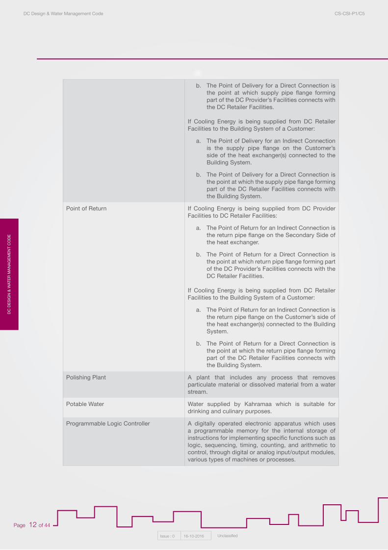
Point of Delivery If Cooling Energy is being supplied from DC Provider Facilities to DC Retailer Facilities:
a. The Point of Delivery for an Indirect Connection is the supply pipe flange on the Secondary Side of the heat exchanger.
DC
DE
SIG
N &
WAT
ER
MA
NA
GE
ME
NT
CO
DE
DC Design & Water Management Code CS-CSI-P1/C5
Issue : 0 16-10-2016 Unclassified
Page 12 of 44
. The Point of Delivery for a Direct Connection is the point at which supply pipe flange forming part of the DC Provider’s Facilities connects with the DC Retailer Facilities.
If Cooling Energy is being supplied from DC Retailer Facilities to the Building System of a Customer:
a. The Point of Delivery for an Indirect Connection is the supply pipe flange on the Customer’s side of the heat exchanger(s) connected to the Building System.
b. The Point of Delivery for a Direct Connection is the point at which the supply pipe flange forming part of the DC Retailer Facilities connects with the Building System.
Point of Return If Cooling Energy is being supplied from DC Provider Facilities to DC Retailer Facilities:
a. The Point of Return for an Indirect Connection is the return pipe flange on the Secondary Side of the heat exchanger.
b. The Point of Return for a Direct Connection is the point at which return pipe flange forming part of the DC Provider’s Facilities connects with the DC Retailer Facilities.
If Cooling Energy is being supplied from DC Retailer Facilities to the Building System of a Customer:
a. The Point of Return for an Indirect Connection is the return pipe flange on the Customer’s side of the heat exchanger(s) connected to the Building System.
b. The Point of Return for a Direct Connection is the point at which the return pipe flange forming part of the DC Retailer Facilities connects with the Building System.
Polishing Plant A plant that includes any process that removes particulate material or dissolved material from a water stream.
Potable Water Water supplied by Kahramaa which is suitable for drinking and culinary purposes.
Programmable Logic Controller A digitally operated electronic apparatus which uses a programmable memory for the internal storage of instructions for implementing specific functions such as logic, sequencing, timing, counting, and arithmetic to control, through digital or analog input/output modules, various types of machines or processes.
a.
b.
DC
DE
SIG
N &
WATE
R M
AN
AG
EM
EN
T CO
DE
DC Design & Water Management Code CS-CSI-P1/C5
Issue : 0 16-10-2016 Unclassified
Page 13 of 44
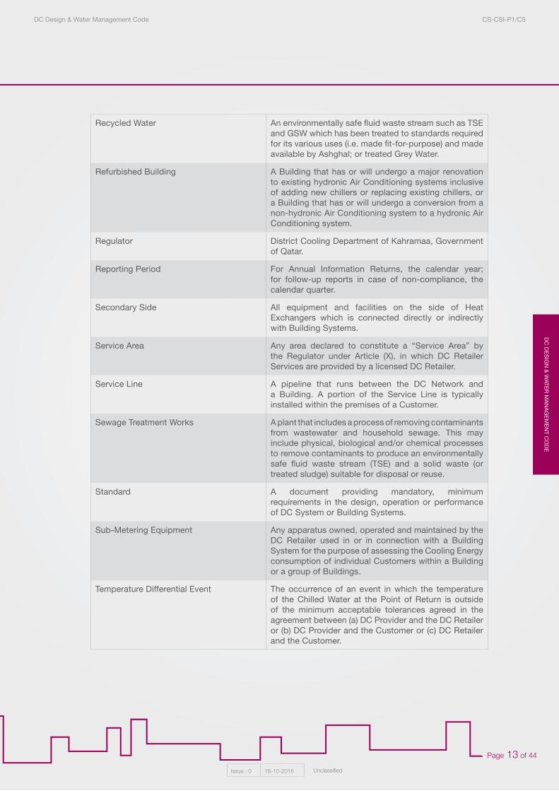
Recycled Water An environmentally safe fluid waste stream such as TSE and GSW which has been treated to standards required for its various uses (i.e. made fit-for-purpose) and made available by Ashghal; or treated Grey Water.
Refurbished Building A Building that has or will undergo a major renovation to existing hydronic Air Conditioning systems inclusive of adding new chillers or replacing existing chillers, or a Building that has or will undergo a conversion from a non-hydronic Air Conditioning system to a hydronic Air Conditioning system.
Regulator District Cooling Department of Kahramaa, Government of Qatar.
Reporting Period For Annual Information Returns, the calendar year; for follow-up reports in case of non-compliance, the calendar quarter.
Secondary Side All equipment and facilities on the side of Heat Exchangers which is connected directly or indirectly with Building Systems.
Service Area Any area declared to constitute a “Service Area” by the Regulator under Article (X), in which DC Retailer Services are provided by a licensed DC Retailer.
Service Line A pipeline that runs between the DC Network and a Building. A portion of the Service Line is typically installed within the premises of a Customer.
Sewage Treatment Works A plant that includes a process of removing contaminants from wastewater and household sewage. This may include physical, biological and/or chemical processes to remove contaminants to produce an environmentally safe fluid waste stream (TSE) and a solid waste (or treated sludge) suitable for disposal or reuse.
Standard A document providing mandatory, minimum requirements in the design, operation or performance of DC System or Building Systems.
Sub-Metering Equipment Any apparatus owned, operated and maintained by the DC Retailer used in or in connection with a Building System for the purpose of assessing the Cooling Energy consumption of individual Customers within a Building or a group of Buildings.
Temperature Differential Event The occurrence of an event in which the temperature of the Chilled Water at the Point of Return is outside of the minimum acceptable tolerances agreed in the agreement between (a) DC Provider and the DC Retailer or (b) DC Provider and the Customer or (c) DC Retailer and the Customer.
DC
DE
SIG
N &
WAT
ER
MA
NA
GE
ME
NT
CO
DE
DC Design & Water Management Code CS-CSI-P1/C5
Issue : 0 16-10-2016 Unclassified
Page 14 of 44
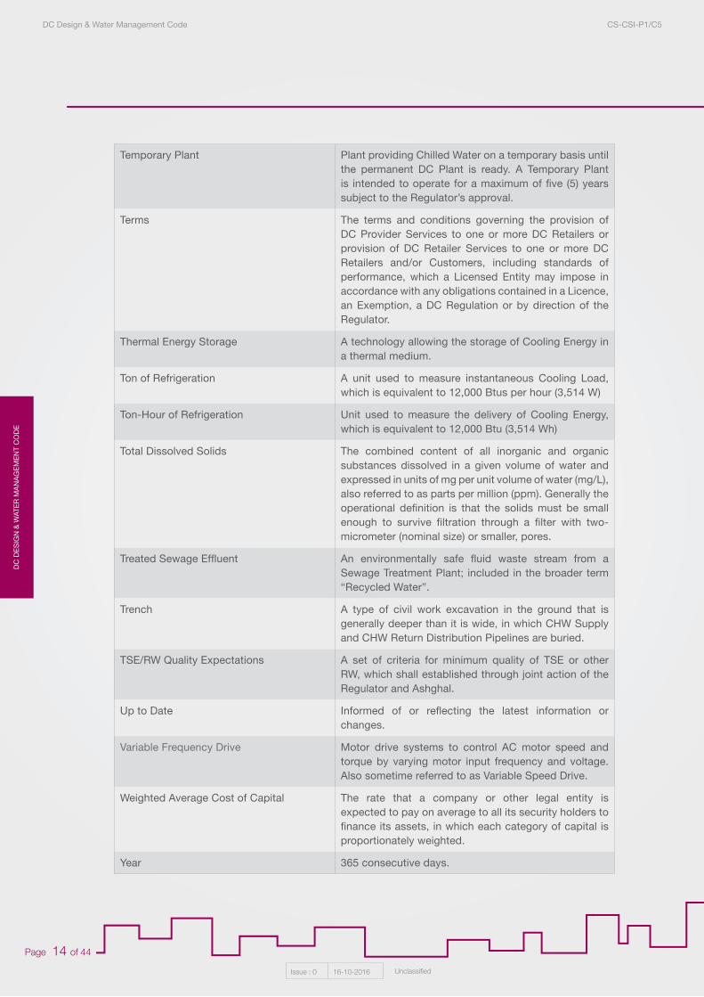
Temporary Plant Plant providing Chilled Water on a temporary basis until the permanent DC Plant is ready. A Temporary Plant is intended to operate for a maximum of five (5) years subject to the Regulator’s approval.
Terms The terms and conditions governing the provision of DC Provider Services to one or more DC Retailers or provision of DC Retailer Services to one or more DC Retailers and/or Customers, including standards of performance, which a Licensed Entity may impose in accordance with any obligations contained in a Licence, an Exemption, a DC Regulation or by direction of the Regulator.
Thermal Energy Storage A technology allowing the storage of Cooling Energy in a thermal medium.
Ton of Refrigeration A unit used to measure instantaneous Cooling Load, which is equivalent to 12,000 Btus per hour (3,514 W)
Ton-Hour of Refrigeration Unit used to measure the delivery of Cooling Energy, which is equivalent to 12,000 Btu (3,514 Wh)
Total Dissolved Solids The combined content of all inorganic and organic substances dissolved in a given volume of water and expressed in units of mg per unit volume of water (mg/L), also referred to as parts per million (ppm). Generally the operational definition is that the solids must be small enough to survive filtration through a filter with two-micrometer (nominal size) or smaller, pores.
Treated Sewage Effluent An environmentally safe fluid waste stream from a Sewage Treatment Plant; included in the broader term “Recycled Water”.
Trench A type of civil work excavation in the ground that is generally deeper than it is wide, in which CHW Supply and CHW Return Distribution Pipelines are buried.
TSE/RW Quality Expectations A set of criteria for minimum quality of TSE or other RW, which shall established through joint action of the Regulator and Ashghal.
Up to Date Informed of or reflecting the latest information or changes.
Variable Frequency Drive Motor drive systems to control AC motor speed and torque by varying motor input frequency and voltage. Also sometime referred to as Variable Speed Drive.
Weighted Average Cost of Capital The rate that a company or other legal entity is expected to pay on average to all its security holders to finance its assets, in which each category of capital is proportionately weighted.
Year 365 consecutive days.
DC
DE
SIG
N &
WATE
R M
AN
AG
EM
EN
T CO
DE
DC Design & Water Management Code CS-CSI-P1/C5
Issue : 0 16-10-2016 Unclassified
Page 15 of 44
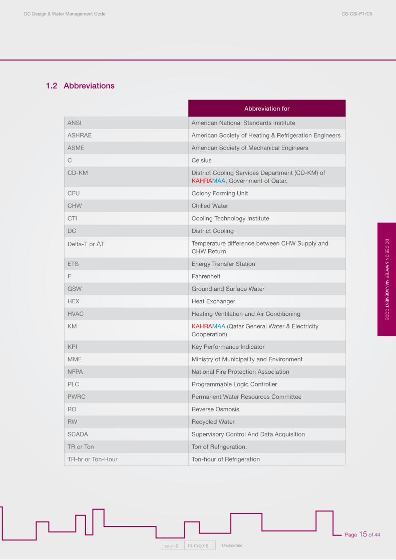
1.2 Abbreviations
Abbreviation for
ANSI American National Standards Institute
ASHRAE American Society of Heating & Refrigeration Engineers
ASME American Society of Mechanical Engineers
C Celsius
CD-KM District Cooling Services Department (CD-KM) of KAHRAMAA, Government of Qatar.
CFU Colony Forming Unit
CHW Chilled Water
CTI Cooling Technology Institute
DC District Cooling
Delta-T or ΔT Temperature difference between CHW Supply and CHW Return
ETS Energy Transfer Station
F Fahrenheit
GSW Ground and Surface Water
HEX Heat Exchanger
HVAC Heating Ventilation and Air Conditioning
KM KAHRAMAA (Qatar General Water & Electricity Cooperation)
KPI Key Performance Indicator
MME Ministry of Municipality and Environment
NFPA National Fire Protection Association
PLC Programmable Logic Controller
PWRC Permanent Water Resources Committee
RO Reverse Osmosis
RW Recycled Water
SCADA Supervisory Control And Data Acquisition
TR or Ton Ton of Refrigeration.
TR-hr or Ton-Hour Ton-hour of Refrigeration
DC
DE
SIG
N &
WAT
ER
MA
NA
GE
ME
NT
CO
DE
DC Design & Water Management Code CS-CSI-P1/C5
Issue : 0 16-10-2016 Unclassified
Page 16 of 44
2.1 General
2.1.1 Purpose
This document deals with the mandatory, minimum requirements for the design and operation of Water Cooled Central Air conditioning Systems for comfort cooling or process cooling applications. For the ease of reference, hereafter in this document, Water cooled central air conditioning plants are named as District Cooling (DC) systems. This standard is applicable to all existing and new DC plants.This document is not intended to comprehensively address all aspects of DC System design and operation. Rather, it is intended to set key minimum requirements deemed critical for achievement of the Key Performance Indicators (KPIs).
2.1.2 Exemptions
Mandatory requirements are not intended to prevent or hinder innovative design approaches. DC Providers shall at all times seek to design DC Systems in the most effective and efficient way and shall have the right to apply for an Exemption from any specific requirement in these Standards. Evidence and related technical studies/justifications shall be submitted to the Kahramaa District Cooling Service department for review and approval or rejection of any proposed Exemption.
2.1.3 Laws and Regulations
The design, installation and operation of a DC System shall be in accordance with the Up to Date jurisdictional authorities, laws and regulations of the State of Qatar. Government agencies having jurisdiction governing DC System include, but are not limited to:
a. Kahramaa (Qatar General Electricity & Water Corporation), of which--
• District Cooling Department serves as Regulator in the District Cooling Regulations;• Electricity Planning Department; and• Water Planning Department:• Customer Services Department:
b. Ashghal (Public Works Authority), which owns and operates systems for Ground and Surface Water (GSW) drainage, Foul Water (FW) Network, Sewage Treatment Plants, and supply of Treated Sewage Effluent (TSE).
T Temperature
TDS Total Dissolved Solids
TES Thermal Energy Storage
TSE Treated Sewage Effluent
VFD Variable Frequency Drive
2. District Cooling Design & Water Management Standards
DC
DE
SIG
N &
WATE
R M
AN
AG
EM
EN
T CO
DE
DC Design & Water Management Code CS-CSI-P1/C5
Issue : 0 16-10-2016 Unclassified
Page 17 of 44
c. Ministry of Municipality and Enviroment (MME), which regulates impacts on the natural environment including dischanges to Ground and Surface drainage and to the sea.
d. Ministry of Interior, of which the Qatar Civil Defence (QCD) is responsible for building codes, regulations and inspections.
Laws and regulations governing DC Systems include, but are not limited to:
a. Law No (30) of 2002 promulgating environmental protection, including associated bylaws and standards, including:
• Annex No. 3 / Second (Standards and Criteria of Wastewater Quality)
1. Standard of Treated Wastewater Used for Irrigation2. Standard for the Discharge of Industrial Effluents into Sewers3. Standards of Ballast Water Discharge4. Standard for Discharging Liquid Waste to the Public Sewage Network for Treatment5. Standard for Treated Sewage Effluents Sanitary Waste Water6. Standard of Cooling Water
• Annex No. 3 / Fourth (Standards of Seawater Quality)
b. Directive by the Permanent Water Resource Committee (PWRC) of the Secretariat General Counsel of Ministers on Prohibition of Potable Water use for Cooling Purpose.
c. Low Voltage Electricity & Water Installations regulations latest edition, Qatar General Electricity & Water Corporation (Kahramaa) Customer Services Department, State of Qatar, latest Edition:
d. Regulations of Internal Water Installations and Connection Works, Qatar General Electricity & Water Corporation (Kahramaa) Customer Services Department, State of Qatar, Latest Edition.
e. Qatar Civil Defence (QCD) codes and regulations.
f. Qatar Construction Specifications (QCS) 2014.
2.2 District Cooling System
2.2.1 General Requirements
The design, fabrication, installation and operation of a DC System shall be fit for purpose operating in the State of Qatar. The DC Provider is accountable to ensure the DC System, once operational, is capable of:
a. Delivering the design Cooling Load; and
b. Operating within the KPIs determined by the Regulator.
DC
DE
SIG
N &
WAT
ER
MA
NA
GE
ME
NT
CO
DE
DC Design & Water Management Code CS-CSI-P1/C5
Issue : 0 16-10-2016 Unclassified
Page 18 of 44
If the design of DC System is found to not meet any of these Standards then the DC Provider shall be required to carry out retrospective work at its own expense to ensure the DC System is compliant.
DC Providers shall operate the DC System based on the following four fundamental principles:
a. All Customers’ Cooling Load requirements can be fully met (up to maximum contracted) at all times. (This does not preclude appropriate use of the Cooling Load Diversity Factor in the DC System design.)
b. Interruption of Services shall be minimized and in all events DC System reliability shall be compliant with KPI 1.
c. Energy and water consumption shall be optimized and in all events shall be compliant with KPIs 2, 3, 4, 5 and 7.
d. Environmental, health and safety impact shall be minimized and in all events shall be compliant
2.2.2 Human Health and Environmental Safety
2.2.2.1 Environmental Protection
a. DC Provider shall obtain approval from MME prior to the construction and operation of the DC System pursuant to the MME requirements.
b. Any discharges from the DC System shall comply with applicable limits or standards for air, noise, land and water.
c. DC Provider shall be compliant with all other laws, regulations and codes promulgated in the State of Qatar relating to health, safety and environmental protection.
2.2 2.2 Access to Facilities
DC Provider shall permit any person authorized by MME or other jurisdictional agency access to any facilities comprising the DC System to inspect at any time for the purpose of verifying compliance with health, safety and environmental regulations.
2.2.2.3 Cross Connection Control and Backflow Prevention
For DC Plants where Potable Water is used as a Makeup Water backup in conjunction with use of TSE, GSW, Grey Water, or other type of Recycled Water the Cooling Tower Makeup Water system design shall include cross connection control and backflow prevention in accordance with the following:
a. The backflow prevention device used shall be either an air gap or a reduced pressure principle backflow assembly suitable for high hazard and potential backpressure applications;
b. Backflow prevention devices shall be periodically inspected by a cross connection control specialist to ensure that they are functioning properly; and
c. All non-Potable Water system shall be prominently labelled as such in both Arabic and English.
with relevant laws, regulations and with KPIs 6 and 8.
DC
DE
SIG
N &
WATE
R M
AN
AG
EM
EN
T CO
DE
DC Design & Water Management Code CS-CSI-P1/C5
Issue : 0 16-10-2016 Unclassified
Page 19 of 44
2.2.2.4 Environmental Management and Monitoring Plan
• DC Provider shall prepare and implement an environmental management and monitoring plan in compliance with MME requirements that includes, but is not limited to, the following:
a. Water Quality
• Blowdown Water• Polishing Plant reject water
b. Air Quality and Other Emissions
• Odor• Noise and vibration• Cooling Tower Drift• Refrigerant leak
c. Other waste streams
• Hazardous wastes• Solid wastes.
d. Dangerous goods
• Water conditioning chemicals
2.2.3 DC Plant
Unless otherwise specified, the following minimum requirements apply to all New Plants, excluding Temporary Plants.
2.2.3.1 Redundancy
Redundancy is a key element that shall be considered in the design to minimize Interruption of Services and maintain compliance with system reliability KPI requirements.
a. DC Plant shall be designed with redundancy (n+1) for electrical equipment and for all life safety equipment.
b. DC Plant shall be served with redundant (n+1) power feeders, such that total DC Plant power demand can be met with one feeder out of service.
c. DC Plant shall be designed with firestops and fire protection systems in accordance with Qatar Civil Defence requirements and NFPA Standards.
2.2.3.2 Process Pumps
Secondary distribution CHW pumps (for primary-secondary pumping schemes) or primary CHW
DC
DE
SIG
N &
WAT
ER
MA
NA
GE
ME
NT
CO
DE
DC Design & Water Management Code CS-CSI-P1/C5
Issue : 0 16-10-2016 Unclassified
Page 20 of 44
pumps (for variable primary pumping schemes) shall incorporate variable flow pumping, and shall be controlled to maintain the minimum required differential pressure at the most hydraulically remote Customer in the DC Network.
2.2.3.3 Pipe Sizing
DC Plant internal pipe sizing shall be performed in accordance with Up to Date ASHRAE Handbook, Fundamentals, to minimize noise, erosion levels and pumping costs.
2.2.3.4 Refrigerant Systems
a. Refrigerant systems, including but not limited to refrigerant piping, refrigerant storage, safety relief valves, alarm systems, emergency ventilation and refrigerant leak detection, shall be designed and sized in accordance with Up to Date ASHRAE Standard 15, Safety Standard for Refrigeration Systems.
b. Refrigerant type used in chillers shall comply with all relevant decisions, rules or procedures mandated by local regulations and international protocols.
2.2.3.5 Cooling Towers
a. Cooling Towers shall be installed with VFD drives to reduce fan speed at part load conditions to minimize annual energy consumption.
b. Cooling Towers shall be sized and field tested in accordance with codes published by CTI or ASME. If the DC Provider wishes to use modifications to these codes or specify another procedure, the DC Provider may apply for an Exemption, subject to the Regulator’s approval.
c. Cooling Towers using unpolished TSE or seawater shall be equipped with cellular type drift eliminators.
2.2.3.6 Thermal Energy Storage (TES)
a. All New Plants with capacity equal to or greater than 10,000 TR shall include a TES system. If the DC Plant is primarily serving cooling loads with a flat daily load profile, such as process loads, the DC Provider may apply for an Exemption from the requirement to include a TES system, subject to the Regulator’s approval.
b. For all New Plants with TES, the TES type shall be stratified CHW TES, except in cases where space limitations or aesthetics do not allow for CHW TES; in these cases the DC Provider may apply for an Exemption to use Ice TES or other TES technology. DC Providers must provide justification for their choice of TES type in their application for Exemption to the Regulator.
c. TES tank(s) shall be sized, at a minimum, for complete load levelling (peak shaving) of the projected peak day load profile for the DC Plant.
d. TES tank walls shall be provided with insulation on all sides, ends, bottom and top of tank. Insulation shall be of adequate thickness to prevent condensation on tank walls and limit heat gain to less than 1% of tank capacity across a twenty-four (24) hour period at 46ºC ambient temperature. Tank exterior shall include a complete vapour barrier and protection of the insulation.
e. For CHW TES tanks, the diffuser shall be designed to resist damage from unanticipated water hammer events that could be initiated elsewhere in the hydraulic system apart from the TES tank.
DC
DE
SIG
N &
WATE
R M
AN
AG
EM
EN
T CO
DE
DC Design & Water Management Code CS-CSI-P1/C5
Issue : 0 16-10-2016 Unclassified
Page 21 of 44
2.2.3.7 Controls, Automation and Metering
a. DC Plant monitoring and control system shall be an industrial grade SCADA system with PLC controllers. The SCADA system shall provide complete process monitoring, control, and troubleshooting capabilities.
b. DC Plant monitoring and control system shall be capable of monitoring and controlling all process equipment (mechanical and electrical), including water treatment systems.
c. Electric meters shall be installed which shall be capable of measuring, displaying and storing data on:
• Hourly total DC Plant electricity consumption; and• Peak instantaneous electricity demand occurring on a daily, monthly and annual basis.
d. Thermal energy meters shall be installed which shall be capable of measuring, displaying and storing data on:
• Hourly total DC Plant Cooling Energy production; and• Hourly peak instantaneous Cooling Load.
e. Flow meters shall be installed which shall be capable of measuring, displaying and storing data on hourly flow of:
• CHW Supply flow to the DC Network;• CHW Makeup Water;• Cooling Tower Makeup Water;• Cooling Tower Blowdown;• TSE or other RW consumption, as appropriate;• Process flows in Polishing Plant, as appropriate;• Potable Water consumption; and• Seawater for Cooling Tower Makeup Water or direct cooling of chiller condensers, as
appropriate.
f. The SCADA system shall be capable of measuring, displaying and storing hourly data on Cooling Energy consumption by each individual DC Retailer and Customer served by the DC System.
g. DC Plant monitoring and control system shall generate automated daily, monthly and yearly reporting for all DC Plant major process variables and equipment operation.
h. DC Provider shall maintain computer logs of hourly data for key process variables, alarm status, and power and water consumption for a rolling three (3) Year period, at minimum, and shall make logs available to the Regulator upon request.
DC
DE
SIG
N &
WAT
ER
MA
NA
GE
ME
NT
CO
DE
DC Design & Water Management Code CS-CSI-P1/C5
Issue : 0 16-10-2016 Unclassified
Page 22 of 44
2.2.4 Water Management
The following requirements apply to all DC Plants excluding Temporary Plants.
2.2.4.1 Regulator Approval of Condenser Cooling Plans
a. DC Providers may implement, consistent with applicable laws and regulations, a range of potential condenser cooling alternatives, including:
• “Polishing” of TSE through Reverse Osmosis, Ultrafiltration and/or other treatment methods, for Cooling Tower Makeup Water;
• Use of unpolished TSE in Cooling Towers in conjunction with an active and continuous water treatment program;
• Other “Recycled Water” sources for Cooling Tower Makeup Water, including Ground and Surface Water (GSW) which has been treated and made available by Ashghal;
• Treated “Grey Water”;• Seawater Cooling Towers; or• Direct cooling of condensers using once-though seawater.
b. DC Providers shall undertake and submit to the Regulator a Condenser Cooling Plan which shall include Life-Cycle Cost Analysis of condenser cooling alternatives at the site or sites for the DC Plant(s). The Condenser Cooling Plan shall consider, among other things, the following:
• When TSE or other RW will be available at the DC Plant site(s) in sufficient quantities to provide for condenser cooling for the DC Plant(s);
• Expected quality of TSE or other RW according to Ashghal;• Capital and operating costs of using TSE or other RW either directly or with a Polishing
Plant;• Capital and operating costs of using seawater for condenser cooling, either in seawater
Cooling Towers or with direct cooling of condensers;• Assessment of the environmental and regulatory requirements for using seawater, and the
associated timelines for meeting regulatory requirements;• Regulatory requirements and associated costs for disposal of wastewater for each
condenser cooling alternative;• Comparison of Life-Cycle Costs of all condenser cooling alternatives, with comparison to
condensing cooling using Potable Water as a base case; and• Proposed plan for condenser cooling, including phasing as appropriate.
c. The Regulator will review and comment on the Condenser Cooling Plan, and either: approve the Condenser Cooling Plan; or provide direction to the DC Provider regarding additional information or analysis required for an approvable Condenser Cooling Plan.
d. DC Providers must receive approval from the Regulator of the Condenser Cooling Plan for a DC System.
2.2.4.2 Criteria for Acceptable Condenser Cooling Plans
a. For New Plants, where TSE or other RW is available in sufficient quantities for the operation of the DC Plant, and the TSE or other RW meets TSE/RW Quality Expectations, TSE or other RW must be used for condenser cooling unless another non-Potable water condenser cooling alternative is more cost effective.
DC
DE
SIG
N &
WATE
R M
AN
AG
EM
EN
T CO
DE
DC Design & Water Management Code CS-CSI-P1/C5
Issue : 0 16-10-2016 Unclassified
Page 23 of 44
b. Where TSE or other RW is not available at the time when design of a New Plant is initiated, but is expected to become available within ten (10) years in sufficient quantities for the operation of the DC Plant, and of sufficient quality to meet TSE/RW Quality Expectations:
• The DC Plant shall be designed with sufficient space and mechanical/electrical capacity to incorporate a TSE polishing plant; and
• Potable Water may be used for Cooling Tower Makeup until such time that TSE or other RW becomes available.
c. In DC Plants using TSE or other RW as the normal source for condenser cooling, Potable Water may be used for Cooling Tower Makeup as an Emergency source of water in the event that TSE or other RW is not available in sufficient quantities or at acceptable quality for more than forty-eight (48) hours.
d. For all DC Plants, Potable Water may be used for closed loop Chilled Water Makeup.
e. Existing DC Plants shall be converted to use TSE or other RW as soon as practicable under the direction of the Regulator.
2.2.4.3 Design Requirements
a. Cooling Tower Makeup Water storage shall be provided with capacity sized for a minimum of forty-eight (48) hours storage based on the projected peak Cooling Tower Makeup Water consumption for the DC Plant.
b. For all applications using seawater, the intake and discharge piping shall be capable of withstanding the aggressive characteristics of seawater and, therefore, non-ferrous materials such as glass-reinforced plastic (GRP) and/or high-density polyethylene (HDPE) are required.
c. For all applications using seawater, chiller condenser materials and seawater Cooling Tower materials shall be capable of withstanding corrosion by seawater, and shall meet the following requirements:
• Chillers shall be constructed of special tube materials (such as titanium or copper-nickel alloys), specially clad tube sheets and internally coated water boxes; and
• Cooling Towers and nearby equipment subject to exposure due to Cooling Tower Drift shall be constructed of corrosion-resistant materials or materials that are protected with coatings suitable for seawater corrosion resistance.
d. All water treatment control, monitoring and alarm functions shall be through the DC Plant monitoring and control system.
2.2.4.4 Cooling Tower Design, Operation and Maintenance
• DC Providers shall create and file with the Regulator a plan to maintain Cooling Tower systems and equipment to comply with Section 7.2 of ANSI/ASHRAE Standard 188-2015, Legionellosis: Risk Management for Building Water Systems.”
DC
DE
SIG
N &
WAT
ER
MA
NA
GE
ME
NT
CO
DE
DC Design & Water Management Code CS-CSI-P1/C5
Issue : 0 16-10-2016 Unclassified
Page 24 of 44
2.2.4.5 Chilled Water Treatment Program
a. The CHW treatment program shall utilize environmentally-friendly approaches and treatment chemicals to the greatest possible extent.
b. The CHW circuit is a low temperature, closed system and therefore protection against corrosion shall be given primary consideration. Secondary consideration shall be given to deposit control and microbiological activity.
c. An automatic dosing system shall be used for the dosing of corrosion inhibitor. The automatic system shall consist of a water meter fitted in the CHW Makeup Water line, chemical dosing pump and storage tank with low-level switch. DC Plant control system shall monitor the quantity of CHW Makeup Water and control the corrosion inhibitor dosing pump based on the Makeup Water rate.
d. The CHW circuit water treatment program shall be designed to control corrosion to less than 1 mpy maximum.
2.2.4.6 Condenser Water Treatment Program
a. The condenser water treatment program should utilize environmentally-friendly approaches and treatment chemicals to the greatest possible extent.
b. The condenser circuit water treatment program, and/or equipment material selection, shall be designed to control or limit corrosion to less than 3 mpy maximum.
c. Dosing pumps and tanks for required chemicals shall be provided with low level alarm.
d. If the condenser cooling approach is use of unpolished TSE in Cooling Towers, then the water treatment system shall be a fully automated system with active monitoring and capable of adjusting water treatment in real time in response to changes in TSE Makeup Water quality.
2.2.4.7 Quarterly Water Quality Analysis
a. The DC Provider shall engage an independent party for inspection and verification of proper execution of the DC Provider’s water treatment equipment and program on a minimum quarterly basis.
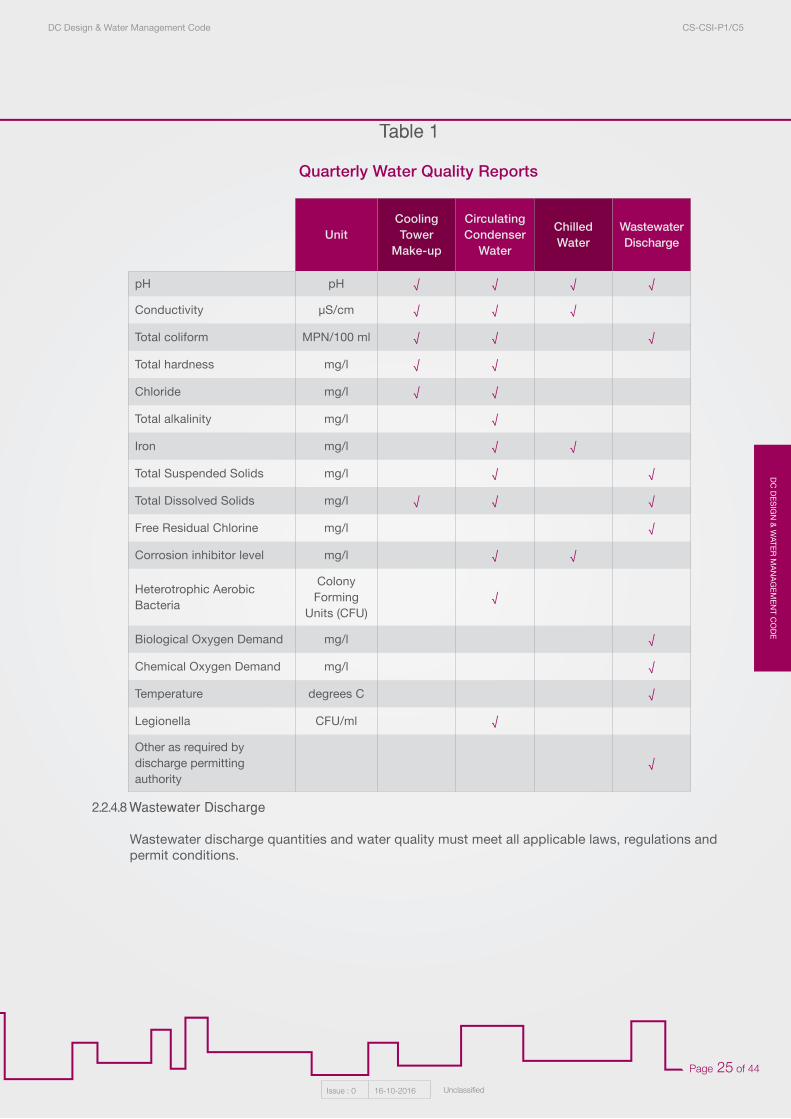
b. Quarterly water quality reports shall be prepared and conveyed to the Regulator and other responsible authorities to ensure compliance with environmental and health requirements. Minimum water parameters to be recorded, in addition to other parameters required by jurisdictional authorities, are indicated in Table 1.
DC
DE
SIG
N &
WATE
R M
AN
AG
EM
EN
T CO
DE
DC Design & Water Management Code CS-CSI-P1/C5
Issue : 0 16-10-2016 Unclassified
Page 25 of 44
Quarterly Water Quality Reports
2.2.4.8 Wastewater Discharge
Wastewater discharge quantities and water quality must meet all applicable laws, regulations and permit conditions.
Table 1
UnitCooling Tower
Make-up
CirculatingCondenser
Water
ChilledWater
WastewaterDischarge
pH pH √ √ √ √
Conductivity μS/cm √ √ √
Total coliform MPN/100 ml √ √ √
Total hardness mg/l √ √
Chloride mg/l √ √
Total alkalinity mg/l √
Iron mg/l √ √
Total Suspended Solids mg/l √ √
Total Dissolved Solids mg/l √ √ √
Free Residual Chlorine mg/l √
Corrosion inhibitor level mg/l √ √
Heterotrophic Aerobic Bacteria
Colony Forming
Units (CFU)√
Biological Oxygen Demand mg/l √
Chemical Oxygen Demand mg/l √
Temperature degrees C √
Legionella CFU/ml √
Other as required by discharge permitting authority
√
DC
DE
SIG
N &
WAT
ER
MA
NA
GE
ME
NT
CO
DE
DC Design & Water Management Code CS-CSI-P1/C5
Issue : 0 16-10-2016 Unclassified
Page 26 of 44
2.2.5 Distribution Pipelines
The minimum requirements in this section apply to all New Distribution Pipelines and extensions of Existing Distribution Pipelines, and apply to both DC Provider Facilities (DC Networks) and Distribution Pipelines comprising part of DC Retailer Facilities.
2.2.5.1 Distribution Pipeline Integrity
a. Distribution Pipelines shall be designed for a life expectancy of a minimum of 40 years.
b. Automatic control or isolation valves shall not be fast-closing valves, or fail closed, unless specific provisions are put in place to mitigate water hammer under these conditions.
c. Distribution Pipeline designs shall incorporate, at strategic locations, sectioning valves (isolation valves) to facilitate repair of Distribution Pipelines while minimizing Interruption of Services.
d. Stress analysis calculations shall be performed to confirm that thermal stresses produced in the DC Network as a result of temperature difference from start-up to operation, pipe pressure, and dead weight, comply with ANSI/ASME B31.1 Power Piping code.
e. Hydrostatic pressure testing of underground Distribution Pipelines shall be performed prior to commissioning and in accordance with Up to Date requirements of ANSI/ASME B31.1 Power Piping code.
f. All underground Distribution Pipelines shall be thoroughly cleaned via flushing or mechanical cleaning before they are put into service.
2.2.5.2 Heat Gain (cold loss)
a. DC Network shall be designed with an annual heat gain less than 4% of annual Cooling Energy for the DC System, at full projected build-out of system.
b. Heat gain calculations shall be performed to determine minimum Distribution Pipeline insulation requirements and to ensure the required CHW Supply temperature is maintained under all Cooling Load conditions.
2.2.5.3 Distribution Pipeline Installation
a. Minimum depth of burial for underground Distribution Pipelines shall be in accordance with local regulations and in accordance with pipe manufacturer’s recommendations to maintain pipeline integrity under required traffic load conditions.
b. In order to ensure DC System reliability and allow for potential repairs, no other utilities shall be placed above or below Distribution Pipelines in the same Trench.
2.2.5.4 Distribution Pipeline Sizing
Hydraulic analysis shall be performed to ensure that required minimum differential pressure is available under all operational conditions for connections to DC-Ready Buildings.
DC
DE
SIG
N &
WATE
R M
AN
AG
EM
EN
T CO
DE
DC Design & Water Management Code CS-CSI-P1/C5
Issue : 0 16-10-2016 Unclassified
Page 27 of 44
2.2.6 Building Connection
This section describes the minimum Building connection design particulars for an efficient and reliable DC System. The requirements of this section apply to all New and Refurbished Buildings unless otherwise noted.
2.2.6.1 Building Connection Type
a. For large-scale DC Systems with multiple DC Retailers and/or a DC System that includes high-rise Buildings, the Building interconnection type shall be Indirect Connection.
b. For small-scale DC Systems, and/or sub-networks within a larger DC System (separated from the main DC System by a HEX), a Direct Connection may be used for service to New Buildings if Building Systems in such Buildings have an appropriate pressure rating.
2.2.6.2 Indirect Connection Type HEX
For Indirect Connections, plate and frame HEX shall be certified in accordance with the AHRI Liquid-to-Liquid Heat Exchanger Certification Program, provided that the capacity of the HEX is encompassed by this certification program at the time of procurement.
2.2.6.3 Chilled Water Flow Control
For all Indirect Connected Buildings:
a. DC Side modulating flow control valve(s) shall control the Building Side CHW Supply temperature. Modulating the flow control valve(s) to control the Building Side or DC Side Return temperature is not acceptable in order to implement the pump control strategy described under Section 2.2.6.4.
b. In order to protect and ensure comfort conditions for all Buildings connected to the DC System, DC Side flow control valves shall have the ability to restrict the flow down to the maximum contracted CHW flow.
c. Two-way modulating flow control valves are mandatory for DC Side ETS Equipment.
For all Direct and Indirect Connected Buildings:
a. Large direct bypasses used for flushing, or other similar start-up purpose, must be removed once the ETS Equipment is in operation.
b. Direct bypass lines shall be avoided, but if a bypass is required it shall include redundant isolation valves to mitigate the possibility of unintended bypass flow.
2.2.6.4 Temperature Differential Event
a. If a Temperature Different Event occurs, Building System CHW pumps shall be controlled by the DC Provider or there must be a means for the DC Provider to override the pump control to ensure the Building Side Supply temperature at all times.
DC
DE
SIG
N &
WAT
ER
MA
NA
GE
ME
NT
CO
DE
DC Design & Water Management Code CS-CSI-P1/C5
Issue : 0 16-10-2016 Unclassified
Page 28 of 44
b. Overriding the pump control may limit Customer comfort and shall only be utilized by the DC Provider on a temporary basis during critical low Delta-T situations while a permanent solution to low Delta-T is being arranged.
2.2.6.5 Bulk-Metering Equipment
The provisions of this section apply to DC Provider Facilities providing DC Service to any New Customer. DC Service may be provided to a Customer directly from the DC Provider acting as DC Retailer or indirectly from the DC Provider through a separate and unrelated DC Retailer to the Customer.
a. The DC Provider shall procure, install, operate and maintain Bulk-Metering Equipment, which shall remain the property of the DC Provider.
b. Where the DC Provider is also the DC Retailer for service to a Customer, the Bulk-Metering Equipment shall be used for billing the Customer for DC Retailer Services.
c. Where the Customer contracts with a DC Retailer other than the DC Provider, the Bulk-Metering Equipment shall be used for billing the DC Retailer for DC Provider Services.
d. Bulk-Metering Equipment shall consist of a CHW flow meter, two paired temperature sensors, and an energy calculator that integrates the CHW flow, temperature data, and correction factors.
e. Bulk-Metering Equipment shall be supplied as a complete unit, factory calibrated with accuracy performance ratings.
f. Flow meters shall be fast responding type in order to ensure adequate performance during short peaks in consumption.
g. The DC Provider shall carry out Periodic Inspection and, as required, reconditioning, of Bulk-Metering Equipment in accordance with KPI service interval requirements and recommendations from the manufacturer of the Bulk-Metering Equipment. Periodic Inspection and reconditioning shall be performed by personnel qualified to carry out such work.
h. Bulk-Metering Equipment must be capable of remote data access and must have data logging capability.
i. Bulk-Metering Equipment Periodic Inspection and reconditioning records shall be maintained by the DC Provider.
j. Bulk-Metering Equipment shall at all times be accurate to a tolerance in accordance with Table 2 in section 2.2.6.7.
2.2.6.6 Sub-Metering Equipment
The provisions of this section apply to DC Retailer Facilities providing DC Retailer Services to any New Customer.
a. The DC Retailer shall procure, install, operate and maintain Sub-Metering Equipment, which shall remain the property of the DC Retailer and shall be used for billing the Customer for DC Retailer Services.
DC
DE
SIG
N &
WATE
R M
AN
AG
EM
EN
T CO
DE
DC Design & Water Management Code CS-CSI-P1/C5
Issue : 0 16-10-2016 Unclassified
Page 29 of 44
b. Sub-Metering Equipment shall consist of a CHW flow meter at a minimum, and may consist of a CHW flow meter, two paired temperature sensors, and an energy calculator that integrates the CHW flow, temperature data and correction factors.
c. Sub-Metering Equipment shall be supplied as a complete unit, factory-calibrated with accuracy performance ratings.
d. Sub-Metering Equipment shall be capable of measuring and recording Cooling Energy consumption by Building Side tenants (or units), common areas and fresh air handling units.
e. Sub-Metering Equipment that is based on CHW flow volumes alone shall be an acceptable Sub-Metering solution provided that all Cooling Loads beyond the Bulk-Metering Equipment have Sub-Metering and that Bulk-Metering Equipment is used to determine Cooling Energy consumption based on the percentage contribution of individual Sub-Metering Equipment CHW consumption relative to aggregate Sub-Metering Equipment CHW consumption.
f. The Sub-Metering and monitoring system shall be designed to accommodate billing allocation for common areas and fresh air based upon Customer rental floor area.
g. Flow meters shall be fast responding type in order to ensure adequate performance during short peaks in consumption.
h. Sub-Metering Equipment shall have data logging capability. Sub-Metering Equipment shall be capable of remote data access, with remote data accessible by the DC Retailer, unless the DC Retailer is granted physical access to the Sub-Metering Equipment to collect logged data.
i. The DC Retailer shall carry out Periodic Inspection and, as required, reconditioning, of Sub-Metering Equipment in accordance with KPI service interval requirements and recommendations from the manufacturer of the Sub-Metering Equipment. Periodic Inspection and reconditioning shall be performed by personnel qualified to carry out such work.
j. Sub-Metering Equipment Periodic Inspection and reconditioning records shall be maintained by the DC Retailer.
k. Sub-Metering Equipment shall at all times be accurate to a tolerance in accordance with Table 2 in section 2.2.6.7. If Sub-Metering solution is based on CHW flow volumes alone, in accordance with section 2.2.6.6. e above, then only flow meter accuracy requirements of Table 2 apply.
2.2.6.7 Maximum Permissible Relative Error of Metering Equipment¹
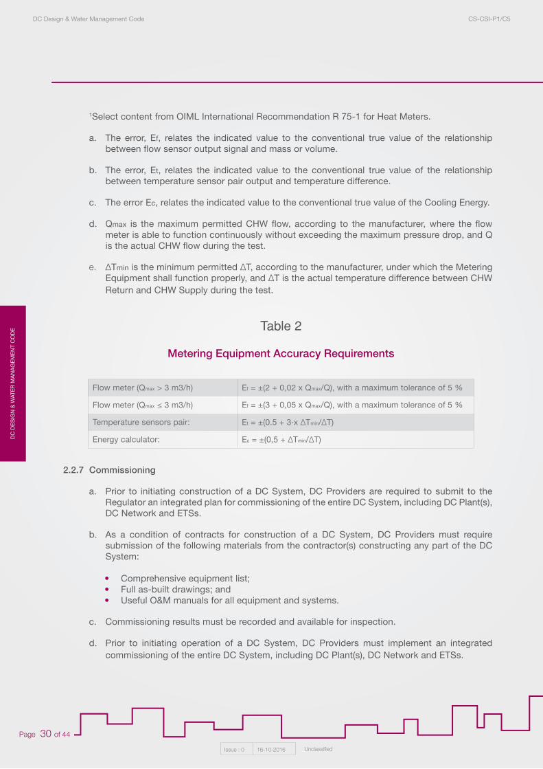
The relative error of Bulk-Metering Equipment and Sub-Metering Equipment, positive or negative, are expressed in percent and calculated from the CHW flow-rate in the case of the flow sensor and CHW temperature difference in the case of the energy calculator and the temperature sensor pair.
Table 2 show the maximum permissible relative error of Bulk-Metering Equipment and Sub-Metering Equipment used for the purposes of billing, where:
DC
DE
SIG
N &
WAT
ER
MA
NA
GE
ME
NT
CO
DE
DC Design & Water Management Code CS-CSI-P1/C5
Issue : 0 16-10-2016 Unclassified
Page 30 of 44
1Select content from OIML International Recommendation R 75-1 for Heat Meters.
a. The error, Ef, relates the indicated value to the conventional true value of the relationship between flow sensor output signal and mass or volume.
b. The error, Et, relates the indicated value to the conventional true value of the relationship between temperature sensor pair output and temperature difference.
c. The error Ec, relates the indicated value to the conventional true value of the Cooling Energy.
d. Qmax is the maximum permitted CHW flow, according to the manufacturer, where the flow meter is able to function continuously without exceeding the maximum pressure drop, and Q is the actual CHW flow during the test.
e. ΔTmin is the minimum permitted ΔT, according to the manufacturer, under which the Metering Equipment shall function properly, and ΔT is the actual temperature difference between CHW Return and CHW Supply during the test.
2.2.7 Commissioning
a. Prior to initiating construction of a DC System, DC Providers are required to submit to the Regulator an integrated plan for commissioning of the entire DC System, including DC Plant(s), DC Network and ETSs.
b. As a condition of contracts for construction of a DC System, DC Providers must require submission of the following materials from the contractor(s) constructing any part of the DC System:
• Comprehensive equipment list;• Full as-built drawings; and• Useful O&M manuals for all equipment and systems.
c. Commissioning results must be recorded and available for inspection.
d. Prior to initiating operation of a DC System, DC Providers must implement an integrated commissioning of the entire DC System, including DC Plant(s), DC Network and ETSs.
Flow meter (Qmax > 3 m3/h) Ef = ±(2 + 0,02 x Qmax/Q), with a maximum tolerance of 5 %
Flow meter (Qmax ≤ 3 m3/h) Ef = ±(3 + 0,05 x Qmax/Q), with a maximum tolerance of 5 %
Temperature sensors pair: Et = ±(0.5 + 3·x ΔTmin/ΔT)
Energy calculator: Ec = ±(0,5 + ΔTmin/ΔT)
Metering Equipment Accuracy Requirements
Table 2
DC
DE
SIG
N &
WATE
R M
AN
AG
EM
EN
T CO
DE
DC Design & Water Management Code CS-CSI-P1/C5
Issue : 0 16-10-2016 Unclassified
Page 31 of 44
1.1 Compliance Requirement
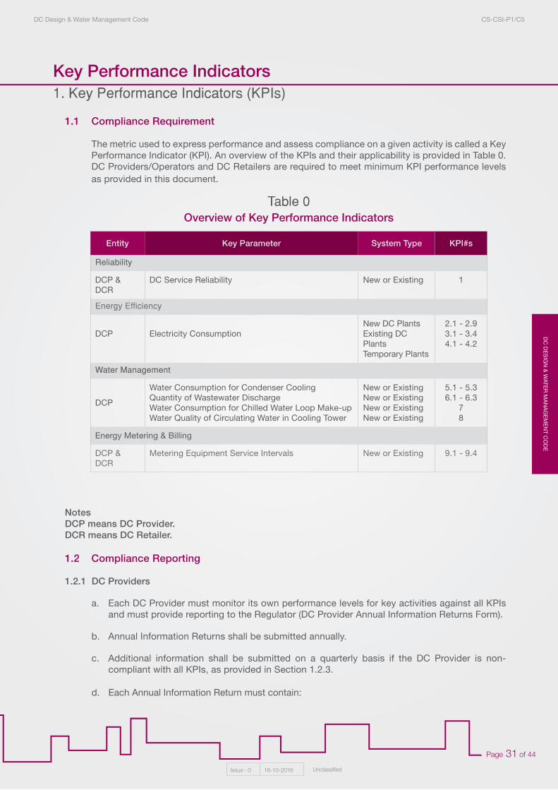
The metric used to express performance and assess compliance on a given activity is called a Key Performance Indicator (KPI). An overview of the KPIs and their applicability is provided in Table 0. DC Providers/Operators and DC Retailers are required to meet minimum KPI performance levels as provided in this document.
NotesDCP means DC Provider.DCR means DC Retailer.
1.2 Compliance Reporting
1.2.1 DC Providers
a. Each DC Provider must monitor its own performance levels for key activities against all KPIs and must provide reporting to the Regulator (DC Provider Annual Information Returns Form).
b. Annual Information Returns shall be submitted annually.
c. Additional information shall be submitted on a quarterly basis if the DC Provider is non-compliant with all KPIs, as provided in Section 1.2.3.
d. Each Annual Information Return must contain:
Entity Key Parameter System Type KPI#s
Reliability
DCP & DCR
DC Service Reliability New or Existing 1
Energy Efficiency
DCP Electricity ConsumptionNew DC PlantsExisting DC PlantsTemporary Plants
2.1 - 2.93.1 - 3.44.1 - 4.2
Water Management
DCP
Water Consumption for Condenser CoolingQuantity of Wastewater DischargeWater Consumption for Chilled Water Loop Make-upWater Quality of Circulating Water in Cooling Tower
New or ExistingNew or ExistingNew or ExistingNew or Existing
5.1 - 5.36.1 - 6.3
78
Energy Metering & Billing
DCP & DCR
Metering Equipment Service Intervals New or Existing 9.1 - 9.4
Overview of Key Performance IndicatorsTable 0
Key Performance Indicators1. Key Performance Indicators (KPIs)
DC
DE
SIG
N &
WAT
ER
MA
NA
GE
ME
NT
CO
DE
DC Design & Water Management Code CS-CSI-P1/C5
Issue : 0 16-10-2016 Unclassified
Page 32 of 44
• Key Performance Indicator performance levels for all key activities;• The nature and extent of any failures to meet minimum KPI performance levels during the
reporting period;• Explanation of the causes of each failure, if any;• Planned corrective actions to prevent recurrence of each failure, if any; and• Other Information that has been reasonably requested by the Regulator in advance of
Annual Information Return submission.
1.2.2 DC Retailers
a. Each DC Retailer must monitor its own performance levels for key activities against KPIs 1 and 9.1-9.4 and must provide reporting to the Regulator (DC Retailer Annual Information Returns, Form CD-P6/F1).
b. Annual Information Returns shall be submitted annually.
c. Additional information shall be submitted on a quarterly basis if the DC Retailer is non-compliant with all KPIs, as provided in Section 1.2.3.
d. Each Annual Information Return must contain:
• Key Performance Indicator performance levels for all key activities;• The nature and extent of any failures to meet minimum KPI performance levels during the
reporting period;• Explanation of the causes of each failure, if any;• Planned corrective actions to prevent recurrence of each failure, if any; and• Other Information that has been reasonably requested by the Regulator in advance of
Annual Information Return submission.
1.2.3 Consequences of Non-Compliance
If a DC Provider or DC Retailer is found to be non-compliant with any of the KPIs:
a. The non-compliant entity must submit a letter, signed by a responsible officer of that entity, with the following information--
• Identification of the reporting period during which non-compliance occurred,• The reported values for the KPI parameter(s) which did not meet the requirement(s),• Discussion of the causes of each failure, and• Corrective actions to be implemented and the schedule for such corrective actions.
b. The non-compliant entity must submit a quarterly update report on the items listed under a. above until performance is brought into compliance; and
c. Information about the non-compliance shall be made publically available until such time that performance is brought into compliance.
DC
DE
SIG
N &
WATE
R M
AN
AG
EM
EN
T CO
DE
DC Design & Water Management Code CS-CSI-P1/C5
Issue : 0 16-10-2016 Unclassified
Page 33 of 44
1.2.4 Other Laws, Standards, Regulations and Codes
Compliance with the KPIs does not absolve the DC Provider or DC Retailer from compliance with all laws, standards, regulations, and codes applicable to their systems and business activities.
1.3 Reliability
DC Providers must operate their DC Provider Facilities, and DC Retailers must operate their DC Retailer Facilities, to minimize Interruption of DC Service. A minimum of one week of notification shall be given to Customers in writing, providing the date of any Planned Interruption of Services and the expected duration of interruption. Planned Interruption of Services shall be scheduled during low-load seasons and outside of Normal Usage Hours whenever possible.
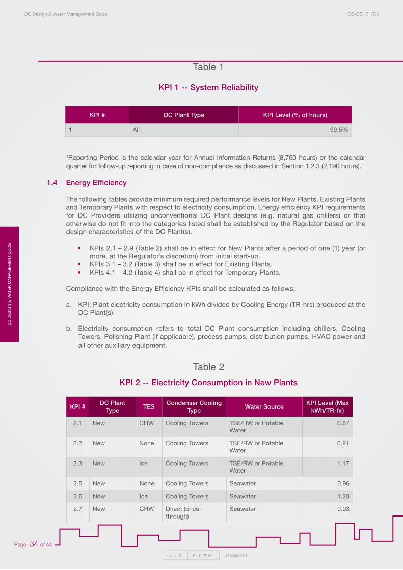
KPI 1 (Table 1) provides the required performance level with respect to DC Provider Service reliability and DC Retailer Service reliability, with the KPI calculated for DC Providers and DC Retailers as follows:
a. For DC Providers, the KPI for the Reporting Period¹ is calculated as follows:
KPI = SHP divided by (THP – FMP)
In which --
• SHP = Number of hours during which DC Provider Services were available to meet the Cooling Load requirements of all DC Retailers under contract at that time (up to maximum Cooling Load requirements contracted).
• THP = Total number of hours during the Reporting Period.• FMP = Number of hours during the Reporting Period during which service to any DC
Retailer by DC Provider was interrupted due to a Force Majeure Event or due to actions of the Retailer or other entity.
b. For DC Retailers, the KPI for the Reporting Period¹ is calculated as follows:
KPI = SHR divided by (THR – FMR)
In which --
• SHR = Number of hours during which DC Retailer Services were available to meet the Cooling Load requirements of all Customers under contract at that time (up to maximum Cooling Load requirements contracted).
• THR = Total number of hours during the Reporting Period.• FMR = Number of hours during the Reporting Period during which service to any Customer
by DC Retailer was interrupted due to a Force Majeure Event or due to actions of the Customer, DC Provider or other entity.
KPI 1 (Table 1) shall be in effect for New Plants after a period of one (1) Year or more from initial start-up (at the Regulator’s discretion). During the first Year of operation (or more at the Regulator’s discretion) a KPI Level of 95% is acceptable.
DC
DE
SIG
N &
WAT
ER
MA
NA
GE
ME
NT
CO
DE
DC Design & Water Management Code CS-CSI-P1/C5
Issue : 0 16-10-2016 Unclassified
Page 34 of 44
1Reporting Period is the calendar year for Annual Information Returns (8,760 hours) or the calendar quarter for follow-up reporting in case of non-compliance as discussed in Section 1.2.3 (2,190 hours).
1.4 Energy Efficiency
The following tables provide minimum required performance levels for New Plants, Existing Plants and Temporary Plants with respect to electricity consumption. Energy efficiency KPI requirements for DC Providers utilizing unconventional DC Plant designs (e.g. natural gas chillers) or that otherwise do not fit into the categories listed shall be established by the Regulator based on the design characteristics of the DC Plant(s).
• KPIs 2.1 – 2.9 (Table 2) shall be in effect for New Plants after a period of one (1) year (or more, at the Regulator’s discretion) from initial start-up.
• KPIs 3.1 – 3.2 (Table 3) shall be in effect for Existing Plants.• KPIs 4.1 – 4.2 (Table 4) shall be in effect for Temporary Plants.
Compliance with the Energy Efficiency KPIs shall be calculated as follows:
a. KPI: Plant electricity consumption in kWh divided by Cooling Energy (TR-hrs) produced at the DC Plant(s).
b. Electricity consumption refers to total DC Plant consumption including chillers, Cooling Towers, Polishing Plant (if applicable), process pumps, distribution pumps, HVAC power and all other auxiliary equipment.
KPI # DC Plant Type KPI Level (% of hours)
1 All 99.5%
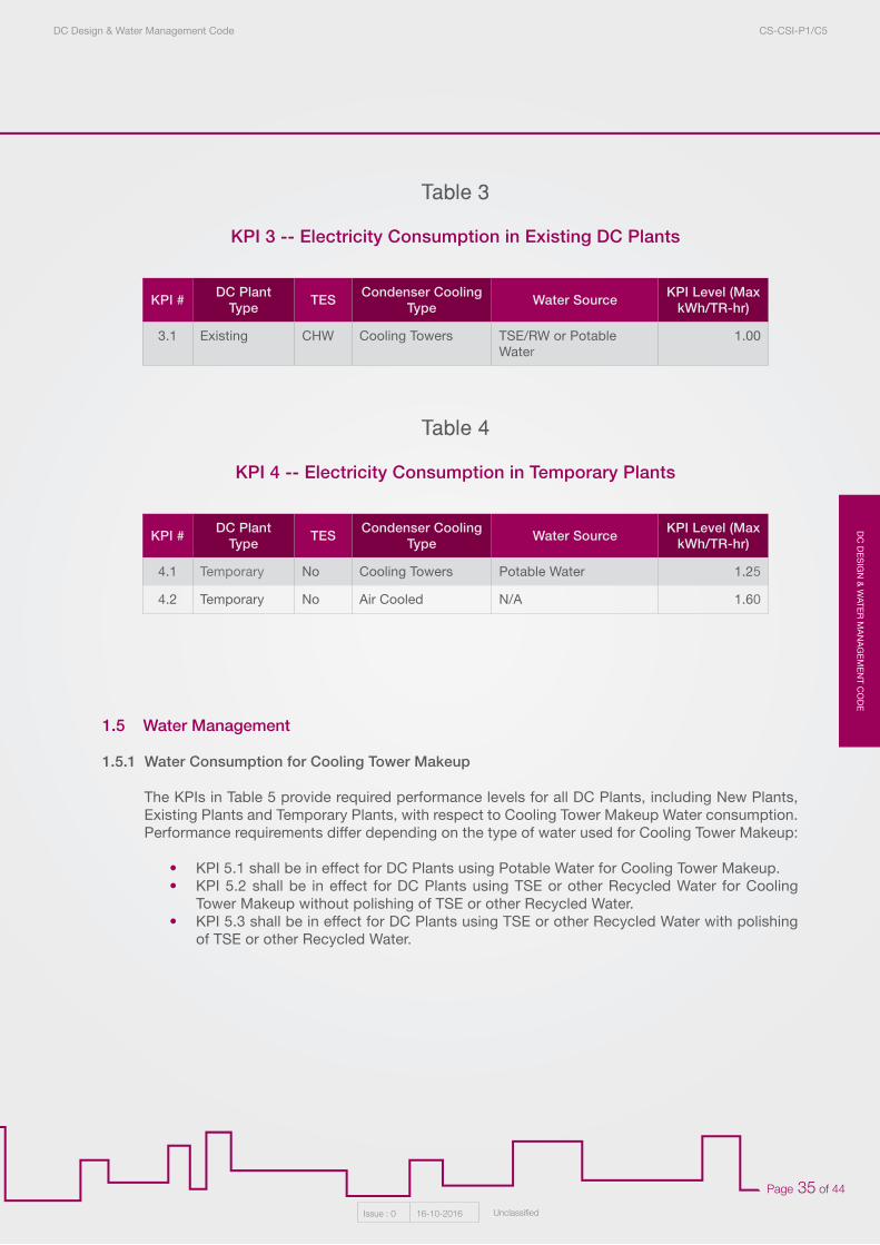
KPI # DC Plant Type TES Condenser Cooling
Type Water Source KPI Level (Max kWh/TR-hr)
2.1 New CHW Cooling Towers TSE/RW or Potable Water
0.87
2.2 New None Cooling Towers TSE/RW or Potable Water
0.91
2.3 New Ice Cooling Towers TSE/RW or Potable Water
1.17
KPI 1 -- System Reliability
KPI 2 -- Electricity Consumption in New Plants
Table 1
Table 2
2.5 New None Cooling Towers Seawater 0.96
2.6 New Ice Cooling Towers Seawater 1.23
2.7 New CHW Direct (once-through)
Seawater 0.93
DC
DE
SIG
N &
WATE
R M
AN
AG
EM
EN
T CO
DE
DC Design & Water Management Code CS-CSI-P1/C5
Issue : 0 16-10-2016 Unclassified
Page 35 of 44
1.5 Water Management
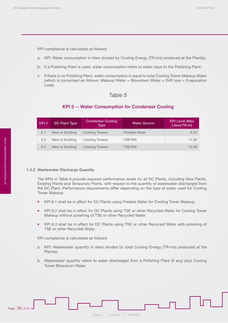
1.5.1 Water Consumption for Cooling Tower Makeup
The KPIs in Table 5 provide required performance levels for all DC Plants, including New Plants, Existing Plants and Temporary Plants, with respect to Cooling Tower Makeup Water consumption. Performance requirements differ depending on the type of water used for Cooling Tower Makeup:
• KPI 5.1 shall be in effect for DC Plants using Potable Water for Cooling Tower Makeup.• KPI 5.2 shall be in effect for DC Plants using TSE or other Recycled Water for Cooling
Tower Makeup without polishing of TSE or other Recycled Water.• KPI 5.3 shall be in effect for DC Plants using TSE or other Recycled Water with polishing
of TSE or other Recycled Water.
KPI # DC Plant Type TES Condenser Cooling
Type Water Source KPI Level (Max kWh/TR-hr)
3.1 Existing CHW Cooling Towers TSE/RW or Potable Water
1.00
KPI # DC Plant Type TES Condenser Cooling
Type Water Source KPI Level (Max kWh/TR-hr)
4.1 Temporary No Cooling Towers Potable Water 1.25
4.2 Temporary No Air Cooled N/A 1.60
KPI 3 -- Electricity Consumption in Existing DC Plants
KPI 4 -- Electricity Consumption in Temporary Plants
Table 3
Table 4
DC
DE
SIG
N &
WAT
ER
MA
NA
GE
ME
NT
CO
DE
DC Design & Water Management Code CS-CSI-P1/C5
Issue : 0 16-10-2016 Unclassified
Page 36 of 44
KPI compliance is calculated as follows:
a. KPI: Water consumption in liters divided by Cooling Energy (TR-hrs) produced at the Plant(s).
b. If a Polishing Plant is used, water consumption refers to water input to the Polishing Plant.
c. If there is no Polishing Plant, water consumption is equal to total Cooling Tower Makeup Water (which is comprised as follows: Makeup Water = Blowdown Water + Drift loss + Evaporation Loss).
1.5.2 Wastewater Discharge Quantity
The KPIs in Table 6 provide required performance levels for all DC Plants, including New Plants, Existing Plants and Temporary Plants, with respect to the quantity of wastewater discharged from the DC Plant. Performance requirements differ depending on the type of water used for Cooling Tower Makeup:
• KPI 6.1 shall be in effect for DC Plants using Potable Water for Cooling Tower Makeup.
• KPI 6.2 shall be in effect for DC Plants using TSE or other Recycled Water for Cooling Tower Makeup without polishing of TSE or other Recycled Water.
• KPI 6.3 shall be in effect for DC Plants using TSE or other Recycled Water with polishing of TSE or other Recycled Water.
KPI compliance is calculated as follows:
a. KPI: Wastewater quantity in liters divided by total Cooling Energy (TR-hrs) produced at the Plant(s).
b. Wastewater quantity refers to water discharged from a Polishing Plant (if any) plus Cooling Tower Blowdown Water.
KPI 5 -- Water Consumption for Condenser Cooling
Table 5
KPI # DC Plant Type Condenser Cooling Type Water Source KPI Level (Max
Liters/TR-hr)
5.1 New or Existing Cooling Towers Potable Water 8.00
5.2 New or Existing Cooling Towers TSE/RW 11.00
5.3 New or Existing Cooling Towers TSE/RW 12.00
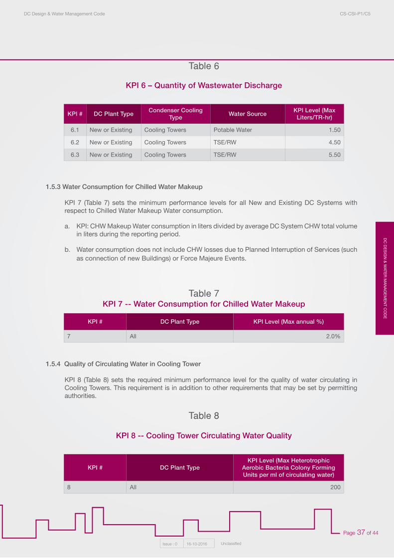
DC
DE
SIG
N &
WATE
R M
AN
AG
EM
EN
T CO
DE
DC Design & Water Management Code CS-CSI-P1/C5
Issue : 0 16-10-2016 Unclassified
Page 37 of 44
1.5.3 Water Consumption for Chilled Water Makeup
KPI 7 (Table 7) sets the minimum performance levels for all New and Existing DC Systems with respect to Chilled Water Makeup Water consumption.
a. KPI: CHW Makeup Water consumption in liters divided by average DC System CHW total volume in liters during the reporting period.
b. Water consumption does not include CHW losses due to Planned Interruption of Services (such as connection of new Buildings) or Force Majeure Events.
1.5.4 Quality of Circulating Water in Cooling Tower
KPI 8 (Table 8) sets the required minimum performance level for the quality of water circulating in Cooling Towers. This requirement is in addition to other requirements that may be set by permitting authorities.
KPI # DC Plant Type Condenser Cooling Type Water Source KPI Level (Max
Liters/TR-hr)
6.1 New or Existing Cooling Towers Potable Water 1.50
6.2 New or Existing Cooling Towers TSE/RW 4.50
6.3 New or Existing Cooling Towers TSE/RW 5.50
KPI 6 – Quantity of Wastewater Discharge
Table 6
KPI # DC Plant Type KPI Level (Max annual %)
7 All 2.0%
KPI # DC Plant TypeKPI Level (Max Heterotrophic
Aerobic Bacteria Colony Forming Units per ml of circulating water)
8 All 200
KPI 7 -- Water Consumption for Chilled Water Makeup
KPI 8 -- Cooling Tower Circulating Water Quality
Table 7
Table 8
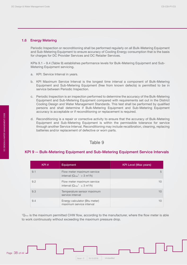
DC
DE
SIG
N &
WAT
ER
MA
NA
GE
ME
NT
CO
DE
DC Design & Water Management Code CS-CSI-P1/C5
Issue : 0 16-10-2016 Unclassified
Page 38 of 44
1.6 Energy Metering
Periodic Inspection or reconditioning shall be performed regularly on all Bulk-Metering Equipment and Sub-Metering Equipment to ensure accuracy of Cooling Energy consumption that is the basis for charges for DC Provider Services and DC Retailer Services.
KPIs 9.1 – 9.4 (Table 9) establishes performance levels for Bulk-Metering Equipment and Sub-Metering Equipment servicing.
a. KPI: Service Interval in years.
b. KPI Maximum Service Interval is the longest time interval a component of Bulk-Metering Equipment and Sub-Metering Equipment (free from known defects) is permitted to be in service between Periodic Inspection.
c. Periodic Inspection is an inspection performed to determine the accuracy of the Bulk-Metering Equipment and Sub-Metering Equipment compared with requirements set out in the District Cooling Design and Water Management Standards. This test shall be performed by qualified persons and shall determine if Bulk-Metering Equipment and Sub-Metering Equipment accuracy is acceptable or if reconditioning or replacement is required.
d. Reconditioning is a repair or corrective activity to ensure that the accuracy of Bulk-Metering Equipment and Sub-Metering Equipment is within the permissible tolerance for service through another Service Interval. Reconditioning may include recalibration, cleaning, replacing batteries and/or replacement of defective or worn parts.
1Qmax is the maximum permitted CHW flow, according to the manufacturer, where the flow meter is able to work continuously without exceeding the maximum pressure drop.
KPI # Equipment KPI Level (Max years)
9.1 Flow meter maximum service interval (Qmax
1¹ > 3 m3/h)5
9.2 Flow meter maximum service interval (Qmax
1¹ ≤ 3 m3/h)10
9.3 Temperature sensor maximum service interval
10
9.4 Energy calculator (Btu meter) maximum service interval
10
KPI 9 -- Bulk-Metering Equipment and Sub-Metering Equipment Service Intervals
Table 9
DC
DE
SIG
N &
WATE
R M
AN
AG
EM
EN
T CO
DE
DC Design & Water Management Code CS-CSI-P1/C5
Issue : 0 16-10-2016 Unclassified
Page 39 of 44
1.7 DC Provider Annual Information Returns
The following Information shall be submitted to the Regulator by the Licensed Entities by March 31 of each year covering performance for the prior calendar year. Data shall be provided in each area indicated in grey. Supporting data shall be attached.
DC Provider Key Performance Indicator Data
Color Codes for KPI Performance Data Form
General Information
Input Value
Company Name
Information Return Date
Respondent Name
Respondent Position
Respondent Email
Respondent Phone Number
Information on and Copy of Corporate Insurance
Values to be inserted
Weighted average calculations (weighting based on % of annual CHW production)
Other calculations as indicated
Performance requirement met? (Yes or No)
System Reliability
KPI # DC Plant Type Minimum KPI Level PErmitted Water Source
1 All 99.5%
Performance Requirements Met?
KPI Level (% of hours)
DC
DE
SIG
N &
WAT
ER
MA
NA
GE
ME
NT
CO
DE
DC Design & Water Management Code CS-CSI-P1/C5
Issue : 0 16-10-2016 Unclassified
Page 40 of 44
Electricity Consumption
Water Consumption for Condenser Cooling
Quantity of Wastewater Discharge
KPI # DC Plant Type TES Condenser Cooling Type Water Source
DC Plant Type as % of Annual
CHW Production
Maximum KPI Level Permitted
Performance Level Achieved by Plant Type
2.1 New CHW Cooling Towers TSE/RW or Potable Water
0.87
2.2 New None Cooling Towers TSE/RW or Potable Water
0.91
2.3 New Ice Cooling Towers TSE/RW or Potable Water
1.17
2.4 New CHW Cooling Towers Seawater 0.91
2.5 New None Cooling Towers Seawater 0.96
2.6 New Ice Cooling Towers Seawater 1.23
2.7 New CHW Direct (once-through) Seawater 0.93
2.8 New None Direct (once-through) Seawater 0.98
2.9 New Ice Direct (once-through) Seawater 1.23
3.1 Existing CHW Cooling Towers TSE/RW or Potable Water
1.00
3.2 Existing None Cooling Towers TSE/RW or Potable Water
1.04
4.1 Temporary None Cooling Towers TSE/RW or Potable Water
1.25
4.2 Temporary None Air Cooled N/A 1.60
Weighted AveragesPerformance Requirement Met?
KPI # DC Plant Type TES Condenser Cooling Type
Water Source
Polishing Plant? DC
Maximum KPI Level Permitted
Performance Level Achieved by Plant Type
5.1 New or Existing
Any Cooling Towers Portable Water
N/A 8.00
5.2 New or Existing
Any Cooling Towers TSE/RW No 11.00
5.3 New or Existing
Any Cooling Towers TSE/RW Yes 12.00
Weighted AveragesPerformance Requirement Met?
KPI # DC Plant Type TES Condenser Cooling Type
Water Source
Polishing Plant? DC
Maximum KPI Level Permitted
Performance Level Achieved by Plant Type
6.1 New or Existing
Any Cooling Towers Portable N/A 1.50
6.2 New or Existing
Any Cooling Towers TSE/RW No 4.50
6.3 New or Existing
Any Cooling Towers TSE/RW Yes 5.50
Weighted AveragesPerformance Requirement Met?
KPI Level (kWh/TR-hr)
KPI Level (liters/TR-hr)
KPI Level (liters/TR-hr)
DC
DE
SIG
N &
WATE
R M
AN
AG
EM
EN
T CO
DE
DC Design & Water Management Code CS-CSI-P1/C5
Issue : 0 16-10-2016 Unclassified
Page 41 of 44
Water Consumption for Chilled Water Distribution Make-up
Bulk-Metering and Sub-Metering Equipment Service Intervals
DC Provider Additional Data for Each DC System
Cooling Tower Circulating Water Quality
KPI # DC Plant Type Total Water Volume in DC Network (liters)
Make-up WaterAdded to DC
Network (liters)
Maximum KPI Level Permitted
Performance Level Achieved by Plant Type
7 All 2.0%
Performance Requirements Met?
KPI # Equipment Maximum KPI Level Permitted Performance Level Achieved
9.1 Flow meter maximum service interval (Qmax1¹ > 3 m3/h) 5
9.2 Flow meter maximum service interval (Qmax1¹ ≤ 3 m3/h) 10
9.3 Temperature sensor maximum service interval 10
9.4 Energy calculator (Btu meter) maximum service interval 10
Performance Requirements Met?
KPI # DC Plant Type Condenser Cooling Type
Maximum KPI Level Permitted
Performance Level Achieved
1st Quarter 2nd Quarter 3rd Quarter 4th Quarter Annual Maximum
8 All Cooling Towers 200
Performance Requirements Met?
KPI Level (% of total water volume)
KPI Level (years)
KPI Level (Heterotrophic Aerobic Bacteria Colony FormingUnits per ml of circulating water)
Input Unit By DC System
Licensed Capacity TR
Installed Chiller Capacity TR
Planned Capacity Increase (within next 5 years) TR
Potential Additional Capacity Increase TR
Thermal Energy Storage Capacity TR
Thermal Energy Storage Capacity m3
Time of Annual Peak Cooling Demand HH/DD/MM/YYYY
Coincident Peak Load TR
DC
DE
SIG
N &
WAT
ER
MA
NA
GE
ME
NT
CO
DE
DC Design & Water Management Code CS-CSI-P1/C5
Issue : 0 16-10-2016 Unclassified
Page 42 of 44
Cooling Energy Production TR-hrs
Delivered Cooling Energy to Customers TR-hrs
Total Electricity Consumption kWh-hrs
Total Consumption of TSE or other RW m3³
Total Consumption of Potable Water m3³
DC Network Length Trench meters
Total Building Area Serviced (Gross Floor Area) m²
Number of Flow Meters Tested Annual Total
Number of Flow Meters Replaced Annual Total
Number of Temperature Sensors Tested Annual Total
Number of Temperature Sensors Replaced Annual Total
Number of Energy Calculators Tested Annual Total
Number of Energy Calculators Replaced Annual Total
DC Provider Additional Data for Each DC Plant
Input Unit By DC System
Plant Address N/A
Commissioning Date DD/MM/YYYY
Temporary Plant? Yes/No
Licensed Capacity TR
Installed Chiller Capacity TR
Planned Capacity Increase (within next 5 years) TR
Potential Additional Capacity Increase TR
Thermal Energy Storage Capacity TR and m3³
Thermal Energy Storage Capacity m3³
Coincident Peak Load Demand TR
Cooling Energy Production TR-hrs
Electricity Consumption kWh
TSE or Other RW Consumption m3³
Potable Water Consumption m3³
DC
DE
SIG
N &
WATE
R M
AN
AG
EM
EN
T CO
DE
DC Design & Water Management Code CS-CSI-P1/C5
Issue : 0 16-10-2016 Unclassified
Page 43 of 44
Maintenance Logs (attachments)
1. Preventive maintenance activities completed during the Reporting Period.
2. Preventive maintenance activities planned but not completed during the Reporting Period.
3. Preventive maintenance activities planned for the following Reporting Period.
Statements of Compliance (attachments)
1. Statement of Compliance with occupational health and safety laws and regulations.
2. Statement of Compliance with environmental laws and regulations.
1.8 DC Retailer Annual Information Returns
The following Information shall be submitted to the Regulator by the Licensed Entities by March 31 of each year covering performance for the prior calendar year. Data shall be provided in each area indicated in grey. Supporting data shall be attached.
DC Retailer Key Performance Indicator Data
Color Codes for KPI Performance Data Form
General Information
Values to be inserted
Weighted average calculations (using % of annual CHW production)
Other calculations as indicated
Performance requirement met? (level achieved less than maximum permitted)? (Yes or No)
Input Value
Company Name
Information Return Date
Respondent Name
Respondent Position
Respondent Email
Respondent Phone Number
Information on and Copy of Corporate Insurance
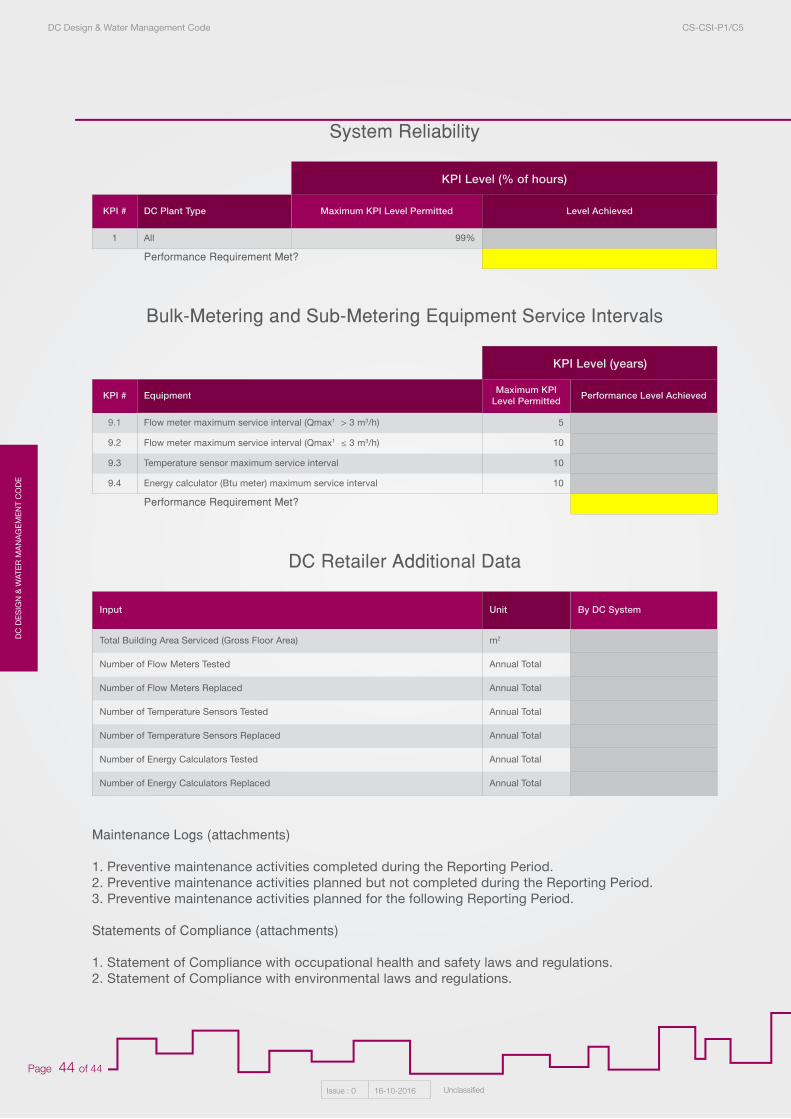
DC
DE
SIG
N &
WAT
ER
MA
NA
GE
ME
NT
CO
DE
DC Design & Water Management Code CS-CSI-P1/C5
Issue : 0 16-10-2016 Unclassified
Page 44 of 44
Maintenance Logs (attachments)
1. Preventive maintenance activities completed during the Reporting Period.2. Preventive maintenance activities planned but not completed during the Reporting Period.3. Preventive maintenance activities planned for the following Reporting Period.
Statements of Compliance (attachments)
1. Statement of Compliance with occupational health and safety laws and regulations.2. Statement of Compliance with environmental laws and regulations.
Bulk-Metering and Sub-Metering Equipment Service Intervals
System Reliability
DC Retailer Additional Data
KPI # Equipment Maximum KPI Level Permitted Performance Level Achieved
9.1 Flow meter maximum service interval (Qmax1¹ > 3 m3/h) 5
9.2 Flow meter maximum service interval (Qmax1¹ ≤ 3 m3/h) 10
9.3 Temperature sensor maximum service interval 10
9.4 Energy calculator (Btu meter) maximum service interval 10
Performance Requirement Met?
KPI # DC Plant Type Maximum KPI Level Permitted Level Achieved
1 All 99%
Performance Requirement Met?
KPI Level (years)
KPI Level (% of hours)
Input Unit By DC System
Total Building Area Serviced (Gross Floor Area) m2
Number of Flow Meters Tested Annual Total
Number of Flow Meters Replaced Annual Total
Number of Temperature Sensors Tested Annual Total
Number of Temperature Sensors Replaced Annual Total
Number of Energy Calculators Tested Annual Total
Number of Energy Calculators Replaced Annual Total