Embed Size (px)
Citation preview

Undercounter Dishwashers
2674 N. Service Road, Jordan Station Ontario, Canada L0R 1S0905/562-4195 Fax: 905/562-4618 Toll-free: 800.263.5798
3765 Champion Blvd.,Winston-Salem, NC 27105336/661-1556 Fax: 336/661-1660 Toll-free: 800.858.4477
Issue Date: 5.15.13
Manual P/N 115281 rev. 0
Printed in the USA
For machines beginning with S/N W130838986 and above
Machine Serial No.
Models: UH130 High Temperature without built-in booster Fill and Refresh Pumped Final Rinse UH130B
UH230B
Installation/Operation Manual with Service Replacement Parts
UH130B High Temperature with built-in booster Fill and Refresh Pumped Final Rinse
UL130 Low Temperature Chemical Sanitization
UH230 High Temperature without built-in booster Fresh Water Final Rinse
UH230B High Temperature with built-in booster Fresh Water Final Rinse

COPYRIGHT © 2013 All rights reserved Printed in the USA
For future reference, record your dishwasher information in the box below.
Model Number__________________________ Serial Number_______________________
Voltage________________Hertz_____________ Phase__________________
Service Agent __________________________________ Tel:______________________
Parts Distributor _________________________________ Tel:______________________
ATTENTION:
The model no., serial no., voltage, Hz and phase are needed to identify your
machine and to answer questions.
The machine data plate is located on the lower front panel.
Please have this information ready if you call for service assistance.
National Service Department
In Canada: In the USA: Toll-free: 800/ 263-5798 Toll-free: 800/ 858-4477Tel: 905/ 562-4195 Tel: 336/ 661-1556 Fax: 905/ 562-4618 Fax: 336/ 661-1660 email: [email protected] email: [email protected]
The USGBC and the CaGBC Member Logos are trademarks owned by the U.S. Green Building Council and The Canadian Green Building Council, respectively, and are used by permission. The logos signify only that Champion is a USGBC member and a
CaGBC member; USGBC and CaGBC do not review, certify nor endorse the products or services offered by its members.
http://www.championindustries.com/canada/register
REGISTER YOUR PRODUCT ONLINEMake sure you are connected to the internet then enter an address below:
In the U.S.A.
In Canada
http://www.championindustries.com/register

PRODUCT REGISTRATION
BY FAX
(336) 661-1660 in the USA
1-(800) 204-0109 in Canada
IMPORTANT IMPORTANT
Model Serial #
Date of Installation:
Company Name:
Telephone #: ( ) ---Contact:
Address:
Address:
Telephone #:
Contact:
Installation Company:
(Street) Province Postal Code
FAILURE TO REGISTER YOUR PRODUCT MAY VOID YOUR WARRANTY
PRODUCT REGISTRATION CARD
COMPLETE THIS FORM AND FAX TO:
i
Revision History
Revision Revised Serial Number Revision Date Pages Effectivity Description
5.15.13 All W130838986 Released First Edition
Revision History A revision might be a part number change, a new instruction, or other information that was not available at print time. We reserve the right to make changes to these instructions without notice and without incurring any liability by making the changes. Equipment owners may request a revised manual, at no charge, by calling 1 (800) 858-4477 in the USA or by calling 1 (800) 263-5798 in Canada.

ii
Limited Warranty
LIMITED WARRANTYChampion Industries Inc. (herein referred to as Champion), 3765 Champion Blvd., Winston-Salem, North Carolina 27105, and P.O. Box 301, 2674 N. Service Road, Jordan Station, Canada, L0R 1S0, warrants machines, and parts, as set out below. Warranty of Machines: Champion warrants all new machines of its manufacture bearing the name "Champion" and installed within the United States and Canada to be free from defects in material and workmanship for a period of one (1) year after the date of installation or fifteen (15) months after the date of shipment by Champion, whichever occurs first. [See below for special provisions relating to glasswashers.] Warranty registration must be submitted to Champion within ten (10) days after installation either online on the Champion Industries website (http://www.championindustries.com/register) in the USA or http://www.championindustries.com/canada/register in Canada or by fax on the form provided at the front of this manual. If warranty registration is not returned to Champion within such period, the warranty will expire after one year from the date of shipment. Champion will not assume any responsibility for extra costs for installation in any area where there are jurisdictional problems with local trades or unions. If a defect in workmanship or material is found to exist within the warranty period, Champion, at its election, will either repair or replace the defective machine or accept return of the machine for full credit; provided; however, as to glasswashers, Champion's obligation with respect to labor associated with any repairs shall end (a) 120 days after shipment, or (b) 90 days after installation, whichever occurs first. In the event that Champion elects to repair, the labor and work to be performed in connection with the warranty shall be done during regular working hours by a Champion authorized service technician. Defective parts become the property of Champion. Use of replacement parts not authorized by Champion will relieve Champion of all further liability in connection with its warranty. In no event will Champion's warranty obligation exceed Champion's charge for the machine. The following are not covered by Champion's warranty: a. Lighting of gas pilots or burners. b. Cleaning of gas lines. c. Replacement of fuses or resetting of overload breakers. d. Adjustment of thermostats. e. Adjustment of clutches. f. Opening or closing of utility supply valves or switching of electrical supply current. g. Cleaning of valves, strainers, screens, nozzles, or spray pipes. h. Performance of regular maintenance and cleaning as outlined in operator’s guide. i. Damages resulting from water conditions, accidents, alterations, improper use, abuse, tampering, improper installation, or failure to follow maintenance and operation procedures. j. Wear on Pulper cutter blocks, pulse vanes, and auger brush.
Examples of the defects not covered by warranty include, but are not limited to: (1) Damage to the exterior or interior finish as a result of the above, (2) Use with utility service other than that designated on the rating plate, (3) Improper connection to utility service, (4) Inadequate or excessive water pressure, (5) Corrosion from chemicals dispensed in excess of recommended concentrations, (6) Failure of electrical components due to connection of chemical dispensing equipment installed by others, (7) Leaks or damage resulting from such leaks caused by the installer, including those at machine table connections or by connection of chemical dispensing equipment installed by others, (8) Failure to comply with local building codes, (9) Damage caused by labor dispute.
Warranty of Parts: Champion warrants all new machine parts produced or authorized by Champion to be free from defects in material and workmanship for a period of 90 days from date of invoice. If any defect in material and workmanship is found to exist within the warranty period Champion will replace the defective part without charge.
DISCLAIMER OF WARRANTIES AND LIMITATIONS OF LIABILITY. CHAMPION'S WARRANTY IS ONLY TO THE EXTENT REFLECTED ABOVE. CHAMPION MAKES NO OTHER WARRANTIES, EXPRESS OR IMPLIED, INCLUDING, BUT NOT LIMITED, TO ANY WARRANTY OF MERCHANTABILITY, OR FITNESS OF PURPOSE. CHAMPION SHALL NOT BE LIABLE FOR INCIDENTAL OR CONSEQUENTIAL DAMAGES. THE REMEDIES SET OUT ABOVE ARE THE EXCLUSIVE REMEDIES FOR ANY DEFECTS FOUND TO EXIST IN CHAMPION DISHWASHING MACHINES AND CHAMPION PARTS, AND ALL OTHER REMEDIES ARE EXCLUDED, INCLUDING ANY LIABILITY FOR INCIDENTALS OR CONSEQUENTIAL DAMAGES.
Champion does not authorize any other person, including persons who deal in Champion dishwashing machines to change this warranty or create any other obligation in connection with Champion Dishwashing Machines.

iii
Table of Contents
Revision History ........................................................................................................ iLimited Warranty ...................................................................................................... iiModel Descriptions ................................................................................................... v
Installation - Models UH130, UH130B, UH230, UH230B ................................. 1
Receiving - All Models.......................................................................................... 1 Placement - All Models ......................................................................................... 1 (Single Phase) Electrical Connections ..................................................................... 3 (Three Phase) Electrical Connections (Field Conversion from 1PH to 3PH Operation) .......... 4 Booster Heater Element (Field Conversion from 1PH to 3PH Operation) ............................ 6 Water Connections .............................................................................................. 7 Drain Connection ................................................................................................ 7
Initial Start-up - Models UH130, UH130B, UH230, UH230B ............................9 Initial Start-up Check List ....................................................................................... 9 Booster Fill Switch - (Filling the booster for the first time) Models UH130B, UH230B Only ...... 10 Pumps and Injection Points - Detergent and Rinse-aid Dispensing Pumps ........................... 12 Pump Priming - Detergent and Rinse-aid Dispensing Pumps ...................................................14 Pump Speed and Fill Adjustments - Detergent and Rinse-aid Dispensing Pumps ....................15
Operation - Models UH130, UH130B, UH230, UH230B ........................................... 16
Loading Dish Racks - All Models ............................................................................ 16 Normal Wash Mode - Models UH130 and UH130B ............................................... 17 Rinse Sentry Mode - Models UH130 and UH130B .................................................. 17 Normal Wash Mode - Models UH230 and UH230B ............................................... 18 Rinse Sentry Mode - Models UH230 and UH230B .................................................. 19 Extended Wash Mode - Models UH230 and UH230B Only ..................................... 19 Drain Mode - All Models ...................................................................................... 20
Cleaning - Models UH130, UH130B, UH230, UH230B .................................... 21
Cleaning the Wash Tank ...................................................................................... 21 Cleaning the Wash Arms - All Models .................................................................... 22 Cleaning the Rinse Arms - Models UH230, UH230B Only) ....................................... 22 De-liming - Models UH230, UH230B ..................................................................... 23 De-liming - Models UH130, UH130B ..................................................................... 24
Maintenance - Models UH130, UH130B, UH230, UH230B ............................... 25 Daily, Weekly, Monthly ........................................................................................ 25 Troubleshooting ................................................................................................... 26
Table of ContentsModels UH130, UH130B, UH230, UH230B, UL130
continued on next page

iv
Table of Contents
Installation - UL130 ............................................................................27
Receiving ........................................................................................................... 1 Placement ........................................................................................................... 1 (Single Phase) Electrical Connections ..................................................................... 28 Water Connections .............................................................................................. 29 Drain Connection ................................................................................................ 30
Initial Start-up - UL130 ........................................................................32 Initial Start-up Check List ....................................................................................... 31 Pumps and Injection Points - Detergent and Rinse-aid Dispensing Pumps ........................... 32 Pump Priming - Detergent and Rinse-aid Dispensing Pumps ...................................................34 Pump Speed and Fill Adjustments - Detergent and Rinse-aid Dispensing Pumps ....................35
Operation - UL130.................................................................................................. 36
Loading Dish Racks ............................................................................................ 36 Normal Wash Mode ........................................................................................... 37 Drain Mode ........................................................................................................ 38
Cleaning - UL130 ................................................................................ 39 Cleaning the Wash Tank ...................................................................................... 39 Cleaning the Wash Arms ..................................................................................... 40 De-liming ............................................................................................................ 41
Troubleshooting and Maintenance -UL130 .................................................. 42 Troubleshooting ................................................................................................... 26 Maintenance - Daily, Weekly, Monthly ................................................................... 42
Service Replacement Parts ..................................................................... 43
Electrical Schematics and Timing Charts ..................................................... 91
Basic Service ..................................................................................... 95
Table of Contents (continued)Models UH130, UH130B, UH230, UH230B, UL130

v
Model Descriptions
UH130B Fill and Refresh Pumped Final RinseHigh temperature hot water sanitizing dishwasher with built-in 40°F/22°C rise booster heater or 70°F/39°C rise booster heater. Two built-in chemical dispensing pumps. Field convertible from single phase to three phase operation. 208-240VAC/60/1 and 3 phase
UH230B Fresh Water Final RinseHigh temperature hot water sanitizing dishwasher with built-in 40°F/22°C rise booster heater or 70°F/39°C rise booster heater. Two built-in chemical dispensing pumps - Detergent, Rinse-aid Field convertible from single phase to three phase operation. 208-240VAC/60/1 and 3 phase
UH130Fill and Refresh Pumped Final Rinse High temperature hot water sanitizing dishwasher without built-in booster heater. Two built-in chemical dispensing pumps - Detergent, Rinse-aid. 208-240VAC/60/1
UH230Fresh Water Final Rinse High temperature hot water sanitizing dishwasher without built-in booster heater. Two built-in chemical dispensing pumps - Detergent, Rinse-aid. 208-240VAC/60/1
UL130Chemical Sanitizing Rinse Low temperature chemical sanitizing dishwasher with three built-in chemical dispensing pumps - Detergent, Rinse-aid, sanitizer. 120VAC/60/1
Optional Equipment (consult factory)
70°F/39°C rise built-in booster heater (UH-230B, and UH130B Only)
70°F/39°C rise booster heater element- P/N 0513331, O-ring - P/N 0513525
1-RDT Right-hand sink - P/N 403562
1-RDT Left-hand sink - P/N 403561
17" Stand - P/N 0708757
6" Stand - P/N 0712393
Peg dish rack - P/N 101285
Flat-bottom dish rack - P/N 101273
Drain water tempering kit - 0712382
Model Descriptions

vi
Blank Page
This Page Intentionally Left Blank

1
NOTE:The installation of your dishwasher must be performed by qualified service personnel. Problems due to improper installation are not covered by the Limited Warranty.
NOTE:The installation of the dishwasher must comply with all local electrical, plumbing, health and safety codes or in the absence of local codes, installed in accordance with the applicable requirements in the National Electrical Code, NFPA 70, Canadian Electrical Code (CEC), Part 1, CSA C22.1; and the Standard for Ventilation Control and Fire Protection of Commercial Cooking Operations, NFPA 96.
Turn to the front of this manual and follow the instructions to register your product online or by fax.
CAUTION:Be careful when lifting and moving the dishwasher to prevent damage to the machine.
NOTE:The installation of the dishwasher must comply with local health codes.
1. Inspect the outside of the dishwasher carton for signs of damage.2. Remove the carton and inspect the dishwasher for damage.3. Check for any options or accessories that may have shipped with your dishwasher.4. Compare the installation site utility connections with the dishwasher utility connections
and make sure they are the same. 5. The dishwasher can be installed as a free-standing unit or under a counter-top.
The typical counter-top height in most locations is 34" [86cm].
6. Under counter installations should provide storage space for the dishwasher chemical supply containers. Do not elevate the containers above the finished floor.
7. Chemical supply containers should be placed as close to the machine as possible.
8. Place the dishwasher in its permanent location.
9. The dishwasher has 4 adjustable feet for leveling.
10. Level the dishwasher front-to-back and side-to-side.
All Models - Installation
Receiving - All Models
Counter-top
Wall
3" [8cm] Min.
34" [86cm]
Min.
Floor
Placement - All Models

2
Installation - Model UH130, UH130B, UH230, UH230B
(Single Phase) Electrical Connections - UH130, UH130B, UH230, UH230B
WARNING: Electrocution or serious injury may result when working on an energized circuit. Disconnect power at the main breaker or service disconnect switch before working on the circuit. Lock-out and tag the breaker or service disconnect switch to indicate that work is being performed on the circuit.
! ATTENTION ! A qualified electrician must connect the main incoming power to the dishwasher in accordance with all local codes and regulations or in the absence of local codes in
accordance with the National Electrical Code or the Canadian Electrical Code.
! VERY IMPORTANT !ALL DISHWASHERS ARE SHIPPED FOR SINGLE PHASE OPERATION UNLESS SPECIFIED
FOR THREE PHASE AT TIME OF ORDER.
A label is attached to the main terminal block alerting the electrician that the dishwasher is wired for single phase operation.
The dishwasher can be converted from single to three phase operation. Refer to the instructions on pages 4-5.
1. Power connections are made at the Main Terminal Block (MTB) located at the lower right-hand side of the dishwasher directly behind the lower front access panel.
2. Remove the MTB cover and 2 screws holding the MTB to the machine base
3. Pull the MTB up and forward to make the electrical connections.
4. Provide a 3 ft. service loop in the supply cable for machine servicing.
5. Re-install the MTB and the lower front access panel to complete the installation.
6. Refer to the connection diagrams on the next page for 1PH wiring.
Main Terminal Block (MTB) (shown extended from machine)
!

3
Model UH130, UH130B, UH230, UH230B - Installation
(Single Phase) Electrical Connections - UH130, UH130B, UH230, UH230B (continued)
Refer to the connection diagrams below to connect main incoming power to the dishwasher.
L1 L2 L3 N
208-230VAC
0 VAC
0 VAC
115VAC
GRD
SINGLE PHASE POWER CONNECTIONModels UH130B and UH230B
Do not connect power to L3
HOW TO CONNECT 1 PHASE POWER
! VERY IMPORTANT !
1. Check the data plate on the front of the dishwasher for the phase of the machine.
.
2. Remove the lower access panel.
3. Pull power connection box forward and out.
4. The Main Terminal Block has connections for L1, L2, L3, Neutral and Ground.
5. Connect ground, then connect L1, L2 to 208-230VAC.
6. Connect a current carrying neutral to N.
7. Main Power connections are complete.
If the data plate says the machine is 1 Phase, then connect a 1 PH power supply.
DO NOT CONNECT POWER TO L3.
THE ELECTRICAL POWER MUST BE A 3-WIRE PLUS GROUND SUPPLY WHICH
INCLUDES A CURRENT CARRYING NEUTRAL.
! VERY IMPORTANT !
SINGLE PHASE UH130B and UH230B The electrical power must be a
3-wire plus ground supply which includes a current carrying neutral.
! ATTENTION ! Models UH130 and UH230 without a built-in booster are equipped with a 4 ft. power cord and plug. These models
require a 115VAC,15A receptacle.
L1 L2
115VAC15A
4 ft. power cord w/plug supplied
SINGLE PHASE POWER CONNECTIONModel UL100

4
Installation - Model UH130, UH130B, UH230, UH230B
(Three Phase) Electrical Connections - UH130, UH130B, UH230, UH230B Field Conversion from Single to Three Phase Operation
! VERY IMPORTANT !ALL DISHWASHERS ARE SHIPPED FOR SINGLE PHASE OPERATION UNLESS SPECIFIED
FOR THREE PHASE AT TIME OF ORDER. A label is attached to the main terminal block alerting the electrician that the
dishwasher is wired for single phase operation.The dishwasher can be converted from single to three phase operation. Refer to the
instructions below and on pages 5-6.
L1 L2 L3 N
208-230VAC
208-230VAC
208-230 VAC
115VAC
GRD
THREE PHASE POWER CONNECTIONModels UH130B and UH230B
HOW TO CONNECT 3 PHASE POWER
1. Check the data plate on the front of the dishwasher for the phase of the machine.
.
2. Remove the lower access panel.
3. Pull power connection box forward and out.
4. The Main Terminal Block has terminals for L1, L2, L3, Neutral and Ground.
5. Connect ground, then connect L1, L2, L3 to 208-230VAC. 6. Connect a current carrying neutral to N.
7. Main power connections are complete.
If the data plate says the machine is 3 Phase, then connect a 3 PH power supply.
! VERY IMPORTANT !THE ELECTRICAL POWER MUST BE A
4-WIRE PLUS GROUND SUPPLY WHICH INCLUDES A CURRENT CARRYING NEUTRAL.
1. Disconnect incoming power at the main breaker or service disconnect switch
2. Lock-out and tag the breaker or service disconnect switch to indicate that work is being performed on the circuit.
3. Power connections are made at the Main Terminal Block (MTB) located at the lower right-hand side of the dishwasher directly behind the lower front access panel.
4. Remove the MTB cover and 2 screws holding the MTB to the machine base
5. Pull the MTB up and forward to make the electrical connections.
6. Provide a 3 ft. service loop in the supply cable for machine servicing.
7. Re-install the MTB and the lower front access panel to complete the installation.
8. Refer to the connection diagram at left for 3PH wiring.
! VERY IMPORTANT !
THREE PHASE UH130B and UH230B The electrical power must be a
4-wire plus ground supply which includes a current carrying neutral.

5
IModel UH130, UH130B, UH230, UH230B - Installation
Booster Heater Element Field Conversion from Single to Three Phase Operation
WARNING: Electrocution or serious injury may result when working on an energized circuit. Disconnect power at the main breaker or service disconnect switch before working on the circuit. Lock-out and tag the breaker or service disconnect switch to indicate that work is being performed on the circuit.
(Three Phase) Electrical Connections - UH130, UH130B, UH230, UH230B (continued) Field Conversion from Single to Three Phase Operation
To convert the booster heater from single phase to three phase operation, locate the booster wire labeled 1H3 cable-tied to the booster hose. Remove the shrink insulation from the terminal and connect to the booster heater element as shown on the wiring diagram on page 6.
The three phase booster wire (1H3) is cable-tied to the hose adjacent to the booster tank.

6
Installation - Model UH130, UH130B, UH230, UH230B
1. Disconnect the main incoming power at the main service disconnect breaker or switch.2. Remove the lower front access panel.3. Locate the 1H3 booster heater wire stored on the right-side of the booster tank.4. Disconnect the existing booster heater wires and change the booster heater element
jumpers as shown in the illustration below5. Connect wires 1H1, 1H2, and 1H3 as shown below.
6. A replacement 3PH data plate is stowed on the back of the lower front access panel. Replace the existing 1PH data plate on the front of the panel with the new 3PH data plate. Discard the 1PH data plate.
1H11H2
1H3
Booster HeaterConnected for 1PH
1H1
Booster HeaterConnected for 3PH
1H21H3
Wire notconnected
Booster heater element connections shown for 1 phase and 3 phase operation.
Booster Heater Element - UH130, UH130B, UH230, UH230B Field Conversion from Single to Three Phase Operation (continued)
A replacement three phase data plate is stowed on the back of the machine lower front access panel.

7
Water Connections - UH130, UH130B, UH230, UH230B
Models UH130B, UH230B
1. All models have a 6 ft. flexible hot water fill hose with a 3/4" female garden hose connector.2. A 1/2" or larger main incoming supply line should be installed to the dishwasher.3. A 1/2" or larger shut-off valve should be installed in the water supply line as close to the
dishwasher for servicing.4. FOR UH230B ONLY: A pressure regulating valve, PRV, (supplied), must be installed after the shut-
off service valve if the incoming flow pressure exceeds 20-22 psi minimum.5. FOR UH130B ONLY: The UH130B has a built-in flow control. The incoming hot water supply
pressure must be between 25-95 psi. 6. The hot water supply must provide a minimum of 140°F/60°C, measured at the dishwasher for
the 40°F/ 22°C rise booster. For the 70°F/39°C rise booster the hot water supply must provide a minimum of 110°F/43°C measured at the dishwasher.
7. A water hardness of 3 grains/gal (US) [51.3 mg/L] or less is recommended.
Models UH130 and UH2301. All models have a 6 ft. flexible hot water fill hose with a 3/4" female garden hose connector.2. A 1/2" or larger main incoming supply line should be installed to the dishwasher. 3. A 1/2" or larger shut-off valve should be installed in the main water supply as close to the
dishwasher as possible for service.4. FOR UH230B ONLY: A pressure regulating valve, PRV, (supplied), must be installed after the shut-
off service valve if the incoming flow pressure exceeds 20-22 psi minimum.5. FOR UH130B ONLY: The UH130B has a built-in flow control. The incoming hot water supply
pressure must be between 25-95 psi. For Models UH130, and UH230, the hot water supply must provide a minimum of 180°F/82°C, measured at the dishwasher.
6. A water hardness of 3 grains/gal (US) [51.3 mg/L] or less is recommended.
Model UH130, UH130B, UH230, UH230B - Installation
NOTEPlumbing connections must comply with national, provincial local plumbing and sanitary codes.
! IMPORTANT ! Make sure that the flexible water supply and drain hoses are not kinked.
Drain Connections All Models
1. All models have a 6 ft.. 5/8" I.D. drain hose. The maximum drain height connection must not exceed 3 ft.[0.9 m].
2. A 3/4" hose barb fitting is strapped to the drain hose to connect the drain hose to a wye drain fitting. . The service part number for the hose barb is P/N 0512321.
8
Installation - Model UH130, UH130B, UH230, UH230B
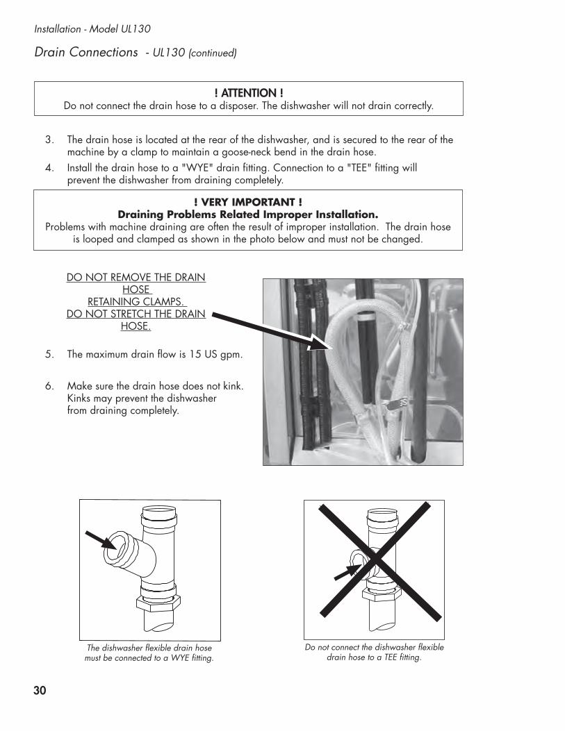
! ATTENTION !Do not connect the drain hose to a disposer. The dishwasher will not drain correctly.
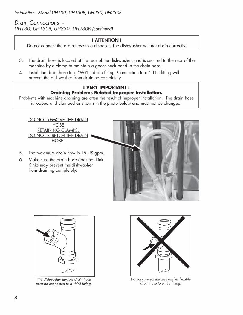
The dishwasher flexible drain hose must be connected to a WYE fitting.
Do not connect the dishwasher flexible drain hose to a TEE fitting.
3. The drain hose is located at the rear of the dishwasher, and is secured to the rear of the machine by a clamp to maintain a goose-neck bend in the drain hose.
4. Install the drain hose to a "WYE" drain fitting. Connection to a "TEE" fitting will prevent the dishwasher from draining completely.
5. The maximum drain flow is 15 US gpm.6. Make sure the drain hose does not kink.
Kinks may prevent the dishwasher from draining completely.
Drain Connections - UH130, UH130B, UH230, UH230B (continued)
! VERY IMPORTANT ! Draining Problems Related Improper Installation.
Problems with machine draining are often the result of improper installation. The drain hose is looped and clamped as shown in the photo below and must not be changed.
DO NOT REMOVE THE DRAIN HOSE
RETAINING CLAMPS. DO NOT STRETCH THE DRAIN
HOSE.

9
Model UH130, UH130B, UH230, UH230B - Initial Start-up
Initial Start-up Check List UH130, UH130B, UH230, UH230B
Make sure the scrap screen is in place.
For Model UH230B only: Make sure the overflow guard is in place.
1. Remove any protective film from dishwasher and check the interior for foreign material. 2. Make sure the dishwasher is permanently located.3. Make sure all utility connections are complete.4. Make sure the flexible drain hose and the hot water fill hose are not kinked.5. Make sure the chemical supply containers are full and the chemical pick-up tubes
are installed in the proper containers.6. Make sure the scrap screen is in place.
7. Make sure the spray arms are in place and spin freely.8. Close the dishwasher door.9. Turn the hot water supply on and check for leaks in the main water supply piping
connected to the dishwasher.
For Model UH230B only: Make sure the overflow guard is in place.

10
Initial Start-up - Model UH130B, UH230B
To refill the booster tank:
1. Remove the lower front panel.
2. Make sure the door is closed.
3. Locate the booster fill switch mounted on the bracket in the center of the machine. Note that the switch is in the OFF position.
4. DO NOT push the dishwasher power switch on the control panel to the ON position.
5. Turn the main power breaker or disconnect switch to the dishwasher ON. Continued on next page
Booster Fill Switch - (Filling the booster tank for the first time) Models UH130B and UH230B only
! VERY IMPORTANT !Models UH130B and UH230B
THE BUILT-IN BOOSTER TANK WAS DRAINED BEFORE SHIPMENT AND
MUST BE REFILLED BEFORE OPERATING THE DISHWASHER.
A BOOSTER FILL SWITCH IS LOCATED BEHIND THE LOWER FRONT PANEL ON THE MACHINE TO REFILL THE BOOSTER TANK.
CAUTION: Do not turn the dishwasher power switch on when refilling the booster tank to prevent permanently damaging the booster heater element.
The Booster Fill Switch is located on the front center bracket behind the lower front access panel.

11
Model UH130B, UH230B - Initial Start-up
Booster Fill Switch - (Filling the booster tank for the first time) Models UH130B and UH230B only
Continued from previous page
6. Push and hold the switch in the FILL position until water is heard spraying inside the dishwasher.
7. Release the switch. It will automatically return to the OFF position.
8. Push the switch to the ON position.
9. Replace the lower front panel.
10. The dishwasher is ready to operate.
11. Push the dishwasher power switch on the control panel to the ON position.
12
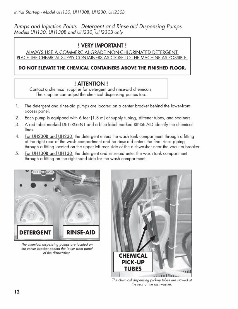
1. The detergent and rinse-aid pumps are located on a center bracket behind the lower-front access panel.
2. Each pump is equipped with 6 feet [1.8 m] of supply tubing, stiffener tubes, and strainers.3. A red label marked DETERGENT and a blue label marked RINSE-AID identify the chemical
lines.4. For UH230B and UH230, the detergent enters the wash tank compartment through a fitting
at the right rear of the wash compartment and he rinse-aid enters the final rinse piping through a fitting located on the upper-left rear side of the dishwasher near the vacuum breaker.
5. For UH130B and UH130, the detergent and rinse-aid enter the wash tank compartment through a fitting on the right-hand side for the wash compartment.
Initial Start-up - Model UH130, UH130B, UH230, UH230B
Pumps and Injection Points - Detergent and Rinse-aid Dispensing Pumps Models UH130, UH130B and UH230, UH230B only
DETERGENT RINSE-AID
CHEMICAL PICK-UP TUBES
The chemical dispensing pumps are located on the center bracket behind the lower front panel
of the dishwasher.
The chemical dispensing pick-up tubes are stowed at the rear of the dishwasher.
! ATTENTION !Contact a chemical supplier for detergent and rinse-aid chemicals.
The supplier can adjust the chemical dispensing pumps too.
! VERY IMPORTANT !ALWAYS USE A COMMERCIAL-GRADE NON-CHLORINATED DETERGENT.
PLACE THE CHEMICAL SUPPLY CONTAINERS AS CLOSE TO THE MACHINE AS POSSIBLE.
DO NOT ELEVATE THE CHEMICAL CONTAINERS ABOVE THE FINISHED FLOOR.

13
Model UH130, UH130B, UH230, UH230B - Initial Start-up
UH230B RINSE-AID INJECTION
POINT
Pumps and Injection Points - Detergent and Rinse-aid Dispensing Pumps Models UH130, UH130B and UH230, UH230B only
UH230BDETERGENT INJECTION
POINT
On the UH130B, chemicals enter the wash tank through a fitting on the right-hand side of the tank.
UH130BDETERGENT
and RINSE-AID INJECTION
POINT
On the UH230B, the rinse-aid enters the wash tank through a fitting in the final rinse piping at the
rear of the machine.
On the UH230B, detergent enters the wash tank through a fitting at the rear of the wash tank.

14
Initial Start-up - Model UH130, UH130B, UH230, UH230B
Pump Priming - Detergent and Rinse-aid Dispensing Pumps Models UH130, UH130B and UH230, UH230B
UH130B Control Panel
WASH RINSE PRIME
DETERGENT
RINSE AIDOFF/DRAIN
ON
POWER
START
TEMPERATURE
1 8 01 5 0
1. The chemical dispensing pump supply lines must be primed before they will pump the chemicals properly.
2. Make sure the chemical containers are full and the correct pick-up tubes are in their containers.
3. Turn the dishwasher power switch ON. The switch will illuminate and the dishwasher will fill with water.
4. Open the dishwasher door, then push and hold the prime push button UP to the DETERGENT position until detergent is observed entering the wash tank compartment. Release the push button.
5. Push and hold the prime push button DOWN to the Rinse-aid position until you see air bubbles moving through the rinse-aid tubing coming out of the chemical container. Release the push button.
6. Close the door to complete the priming operation.
PRIME
DETERGENT
RINSE AID
! VERY IMPORTANT !The chemical dispensing pumps must be primed before operating the dishwasher.
Priming the Dispensing Pumps
WASH RINSE PRIMEEXT WASH
DETERGENT
RINSE AIDOFF/DRAIN
ON
POWER
START
TEMPERATURE
1 8 01 5 0
UH230B Control Panel

15
Model UH130, UH130B, UH230, UH230B - Initial Start-up
Pump Speed and Fill Adjustments - Detergent and Rinse-aid Dispensing Pumps Models UH130, UH130B and UH230, UH230B only
! ATTENTION !Contact a chemical supplier for detergent and rinse-aid chemicals.
The chemical supplier can adjust the chemical dispensing pumps too.
Chemical Dispensing Pump Speed and Tank Fill Adjustments
1. Adjustment screws are provided for the dispensing pumps and for the wash tank fill. They are located on the right-hand side of the dishwasher behind the lower front access panel.
2. Make sure the chemical containers are full and the pick-up tubes are in their proper containers.
3. Turn the dishwasher power switch ON. The switch will illuminate and the dishwasher will fill with water.
4. Run a normal dishwasher cycle and test detergent and rinse-aid concentrations according to the chemical supplier's instructions.
CAUTION: Excessive pressure to the potentiometers when adjusting can result in bent or broken adjusting
screws.
5. Each dispensing pump has a clearly marked adjustment screw. Turn the screw CW to increase the run time of the dispensing pump and CCW to reduce the run time of the dispensing pump.
6. The Fill adjustment screw will provide a small change in the tank water level. If a large adjustment is needed, check the incoming water pressure and make sure the fill hose is not kinked. If the above items are okay then the size of the incoming water supply should be checked. The incoming water supply line must be a minimum of 1/2" or larger.
16
Operation - Models UH130, UH130B and UH230, UH230B
Operation - Models UH130, UH130B and UH230, UH230B
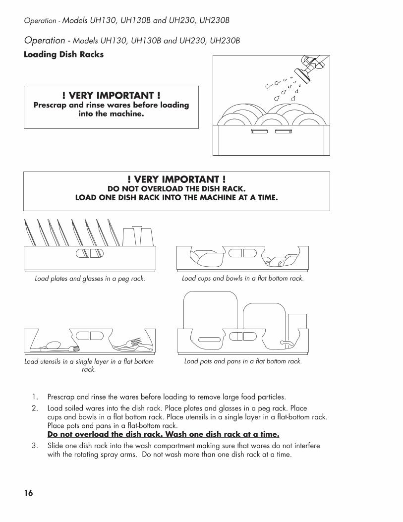
Loading Dish Racks
! VERY IMPORTANT ! DO NOT OVERLOAD THE DISH RACK.
LOAD ONE DISH RACK INTO THE MACHINE AT A TIME.
Load plates and glasses in a peg rack. Load cups and bowls in a flat bottom rack.
1. Prescrap and rinse the wares before loading to remove large food particles.2. Load soiled wares into the dish rack. Place plates and glasses in a peg rack. Place
cups and bowls in a flat bottom rack. Place utensils in a single layer in a flat-bottom rack. Place pots and pans in a flat-bottom rack. Do not overload the dish rack. Wash one dish rack at a time.
3. Slide one dish rack into the wash compartment making sure that wares do not interfere with the rotating spray arms. Do not wash more than one dish rack at a time.
Load utensils in a single layer in a flat bottom rack.
Load pots and pans in a flat bottom rack.
! VERY IMPORTANT ! Prescrap and rinse wares before loading
into the machine.

17
Models UH130, UH130B - Operation
Operation - Models UH130, UH130B Only
Wash Temperature Digital Display Final Rinse Temperature
Digital Display
Prime Push button
In-cycle Light
Start Push button
ON-OFF/DRAIN Power Switch
UH130B Control Panel
WASH RINSE PRIME
DETERGENT
RINSE AIDOFF/DRAIN
ON
POWER
START
TEMPERATURE
1 8 01 5 0
1. Close the dishwasher front door.2. Push the dishwasher Power Switch UP to turn the power ON.3. The power switch will illuminate and the machine will fill with water.4. Wait until the wash temperature gauge indicates a minimum of 150ºF/66ºC.
RUN THE FIRST CYCLE EMPTY TO HEAT THE WASH TANK INTERIOR.
5. Load the dish rack into the machine. Wash one dish rack at a time.6. Close the door, then press the START BUTTON for 1 second. The green in-cycle
light will illuminate and the wash cycle will begin. The total cycle is approximately 141 seconds.
7. Opening the door during a cycle will stop the dishwasher. The cycle will resume automatically when the dishwasher door is closed.
8. The final rinse cycle begins at the end of the wash cycle. The machine drains and then refills with fresh water hot water. Check the rinse temperature gauge during the final rinse. It must indicate a minimum of 180-195ºF/82-91ºC. The final rinse water is retained for the next wash cycle.
9. When the green cycle light goes out, open the door and remove the rack of clean wares.
Normal Wash Mode
! ATTENTION ! DOOR LEFT OPEN DURING WASH CYCLE
If the dishwasher door is left open for more than 5 seconds during the normal wash mode, then the dishwasher cycle will reset to the beginning of the normal wash cycle.
! ATTENTION ! RINSE SENTRY MODE WILL EXTEND WASH CYCLE TIME
In the event that the final rinse temperature has not reached 180-195ºF/82-91ºC after thewash cycle, the rinse sentry will extend the wash cycle time until the booster reaches
180-195ºF/82-91ºC. If the proper temperature is not reached within 5 minutes, the machine will leave the rinse sentry mode and complete the cycle.

18
1. Close the door.2. Push the dishwasher Power Switch UP to turn the power ON.3. The power switch will illuminate and the machine will fill with water.4. Check the pressure gauge as the machine fills and make sure the incoming water pressure
is between 20-22 PSI.5. Wait until the wash temperature gauge indicates a minimum of 150ºF/66ºC.
RUN THE FIRST CYCLE EMPTY TO HEAT THE WASH TANK INTERIOR.
6. Load the dish rack into the machine. Wash one dish rack at a time.7. Close the door, then press the START BUTTON for 1 second. The green in-cycle
light will illuminate and the wash cycle will begin. The total cycle is approximately 90 seconds.
8. Opening the door during a cycle will stop the dishwasher. The cycle will resume automatically when the dishwasher door is closed.
9. The final rinse cycle begins at the end of the wash cycle. The machine drains and retains a portion of the final rinse water for the next wash cycle.
10. Check the rinse temperature gauge during the final rinse. It must indicate a minimum of 180-195ºF/82-91ºC. The final rinse water is retained for the next wash cycle.
11. Check the pressure gauge during the final rinse to ensure the gauge reads 20-22 PSI.12. When the green cycle light goes out, open the door and remove the rack of clean wares.
Operation - Models UH230 and UH230B Only
Operation - Model UH230 and UH230B OnlyNormal Wash Mode
Extended Wash Cycle Light
Extended Wash Push button
Wash Temperature Digital Display
Final Rinse Temperature Digital Display
Prime Push button
Cycle Light Start Push button
ON-OFF/DRAIN Power Switch
WASH RINSE PRIMEEXT WASH
DETERGENT
RINSE AIDOFF/DRAIN
ON
POWER
START
TEMPERATURE
1 8 01 5 0
UH230B Control Panel
WASH RINSE PRIMEEXT WASH
DETERGENT
RINSE AIDOFF/DRAIN
ON
POWER
START
TEMPERATURE
8 8 88 8 8
10
0
3020
PSI
60
50
40
Check the pressure gauge during the final rinse to ensure the gauge reads 20-22 psi.

19
Models UH130, UH130B, UH230, UH230B - Operation
! ATTENTION ! DOOR LEFT OPEN DURING WASH CYCLE
If the dishwasher door is left open for more than 5 seconds during the normal wash mode, then the dishwasher cycle will reset to the beginning of the normal wash cycle.
! ATTENTION ! RINSE SENTRY MODE WILL EXTEND WASH CYCLE TIME
In the event that the final rinse temperature has not reached 180-195ºF/82-91ºC after thewash cycle, the rinse sentry will extend the wash cycle time until the booster reaches
180-195ºF/82-91ºC. If the proper temperature is not reached within 5 minutes, the machine will leave the rinse sentry mode and complete the cycle.
Operation - Model UH230 and UH230B Only (continued)
Extended Wash Mode Model UH230, UH230B Only
The Extended Wash Mode is used to wash heavily soiled items such as pots, pans and other wares that require more washing time than the standard 90 second Normal Wash Mode. The dishwasher will remain in the Extended Wash Mode until the operator exits the mode.
1. Load a dish rack into the dishwasher, close the door and press the START button.2. The green in-cycle light will illuminate and the dishwasher will begin a normal wash cycle.3. Wait 10 seconds for the detergent to enter the wash compartment.
4. Press the EXT WASH button to place the dishwasher in the Extended Wash Mode.5. The green extended wash light will illuminate indicating that the machine is in the
Extended Wash Mode.6. The dishwasher will continue to wash for a maximum of 15 minutes unless the operator
presses the EXT WASH button again.7. Press the EXT WASH button. The green extended wash light will go out indicating that
the dishwasher has returned to the Normal Wash Mode.8. The dishwasher will finish the wash cycle and perform a final rinse of the wares.
EXT WASH
Press the EXT WASH button to place the machine into the extended wash mode to
clean heavily soiled wares.

20
Operation - Models UH130, UH130B and UH230, UH230B
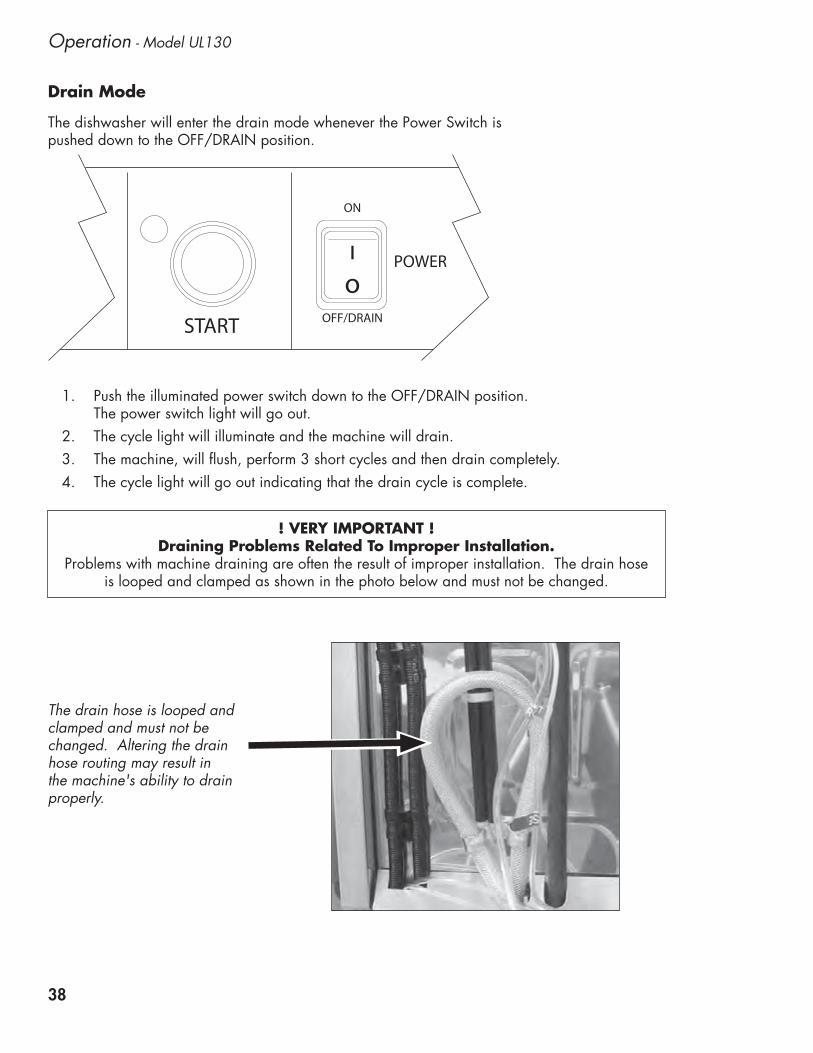
Drain Mode
Operation - Models UH130, UH130B and UH230, UH230B
1. Push the illuminated power switch down to the OFF/DRAIN position. The power switch light will go out.
2. The cycle light will illuminate and the machine will drain.3. The machine, will flush, perform 3 short cycles and then drain completely.4. The cycle light will go out indicating that the drain cycle is complete.
OFF/DRAIN
ON
POWER
START
The dishwasher will enter the drain mode whenever the Power Switch is pushed down to the OFF/DRAIN position.
! VERY IMPORTANT ! Draining Problems Related To Improper Installation.
Problems with machine draining are often the result of improper installation. The drain hose is looped and clamped as shown in the photo below and must not be changed.
The drain hose is looped and clamped and must not be changed. Altering the drain hose routing may result in the machine's ability to drain properly.

21
Models UH130, UH130B and UH230, UH230B - Cleaning
Models UH130, UH130B, UH230, UH230B - Cleaning
Model UH130B Wash Tank
Scrap Screen
Wash Arm
Wash arm and
Rinse ArmScrap Screen
Overflow Guard
Model UH230B Wash Tank
Sump Strainer All Models
1. Remove the upper and lower spray arms and flush clean in a sink.
2. UH230B ONLY: Remove and clean the overflow guard.
3. Remove the scrap screen and flush clean in a sink. Be sure to back-flush the screen.
4. DO NOT strike the scrap screen on solid surfaces.
5. Check the sump for foreign material.
6. Clean the sump strainer in the bottom of the sump.
7. DO NOT scrub the interior with metal scrub pads.
8. Check the sump heating element for lime deposits and gently remove with a stainless steel scouring pad. DO NOT USE STEEL WOOL.
9. Wipe the exterior of the dishwasher with a soft clean cloth and a mild detergent.
10. Leave the door open to aid in overnight drying.
! VERY IMPORTANT !
DRAIN AND CLEAN THE DISHWASHER EVERY 2
HOURS OF CONTINUOUS OPERATION, AFTER EACH
MEAL PERIOD, AND AT THE END OF THE DAY.
Cleaning the wash tank:
Continued on next page

22
Cleaning - Models UH130, UH130B, UH230, UH230B -
Cleaning the wash arms:
Cleaning - Models UH130, UH130B and UH230, UH230B
1. There are two wash arms in the UH130, UH130B, the UH230 and UH230B. They are interchangeable.
2. The UH130, UH130B wash arms are combination wash/rinse arms. The UH230, UH230B are wash arms only.
3. The wash arms should be removed and thoroughly flushed clean in a sink.
4. Special attention should be paid to the cleaning and inspection of the wash arm bearings making sure they are clean and free of excessive wear.
5. If the bearings are damaged, contact an authorized service agent for replacement.
Model UH230B Only Disassemble the rinse arm assembly.
Models UH130B and UH230B Clean the upper and lower wash arm bearings.
1. There are two rinse arms in the UH230, and UH230B. They are interchangeable.
2. Special attention should be paid to the cleaning and inspection of the rinse arm bearings making sure they are clean and free of excessive wear.
3. If the bearings are damaged, contact an authorized service agent for replacement.
4. The rinse arm spray nozzles should be inspected and if necessary, cleaned with a small paper clip or wire.
5. The rinse arm pipes can be flushed out by removing the pipe end plugs with a flat blade screw driver.
Cleaning the rinse arms (UH230, UH230B Only):
Model UH230B Only Clean the upper and lower rinse arm bearings.
Model UH230B Only Rinse arm nozzles and end plugs are located on
the rinse arm pipes.

23
Models UH230, UH230B - De-liming
Minerals (scale) accumulate on the interior surfaces of the dishwasher. The removal of scale deposits is called de-liming. Inspect your machine interior for scale deposits. If de-liming is required, a de-liming agent should be used in accordance with your chemical supplier's instructions.
Model UH230, UH230B De-liming
DANGER:Death or serious injury may result when de-liming solution is mixed with sodium hypochlorite sanitizing agent. Mixing may cause hazardous gases to form. De-liming solution and other acids must never be mixed with chlorine, iodine, bromine, or fluorine.
CAUTION:Skin contact with de-liming solutions can cause severe irritation and possible chemical burns. Always wear eye protection, rubber gloves and protective clothing when handling chemicals.
! VERY IMPORTANT !
CONTACT YOUR CHEMICAL SUPPLIERFOR THE PROPER DELIMING CHEMICALS.
FOLLOW YOU CHEMICAL SUPPLIER'S INSTRUCTIONS MAKING SURE
TO WEAR ALL NECESSARY PROTECTION INCLUDING EYE PROTECTION, RUBBER GLOVES AND PROTECTIVE CLOTHING
WHEN HANDLING CHEMICALS.

24
De-liming - Models UH130, UH130B
Model UH130, UH130B De-liming
DANGER:Death or serious injury may result when de-liming solution is mixed with sodium hypochlorite sanitizing agent. Mixing may cause hazardous gases to form. De-liming solution and other acids must never be mixed with chlorine, iodine, bromine, or fluorine.
CAUTION:Skin contact with de-liming solutions can cause severe irritation and possible chemical burns. Always wear eye protection, rubber gloves and protective clothing when handling chemicals.
! VERY IMPORTANT !
CONTACT YOUR CHEMICAL SUPPLIERFOR THE PROPER DELIMING CHEMICALS.
FOLLOW YOU CHEMICAL SUPPLIER'S INSTRUCTIONS MAKING SURE
TO WEAR ALL NECESSARY PROTECTION INCLUDING EYE PROTECTION, RUBBER GLOVES AND PROTECTIVE CLOTHING
WHEN HANDLING CHEMICALS.
Minerals (scale) accumulate on the interior surfaces of the dishwasher. The removal of scale deposits is called de-liming. Inspect your machine interior for scale deposits. If de-liming is required, a de-liming agent should be used in accordance with your chemical supplier's instructions.
25
Models UH130, UH130B, UH230, UH230B - Maintenance
Maintenance - Models UH130, UH130B and UH230, UH230B
Daily Maintenance
1. Make sure the water supply is on and that the drain is not clogged.2. Check the temperature gauges and/or displays to ensure they are operating.3. Make sure the dish racks are in good condition.4. Check the chemical containers and refill as required.5. Follow the cleaning procedures provided in the Cleaning Section.
Weekly Maintenance
1. Perform Steps 1-5 in the Daily Maintenance.2. Inspect water lines for leaks.3. Check for water leaks underneath the dishwasher.4. Make sure the flexible water fill and drain hoses are not kinked. 5. Make sure that the dishwasher is level.6. Clean accumulated lime deposits from the wash tank heating element.7. Inspect the scrap screen and replace it if damaged.8. Check the spray arms and replace or repair if damaged.
Monthly Maintenance
1. Perform the Daily and Weekly Maintenance listed above.2. Clean the chemical dispenser pick-up tubing for the chemical dispensing pumps.
To clean the pick-up tubing:1. Remove the pick-up tubes from their containers.2. Place each tube in a separate container of hot water.3. Press and hold the PRIME buttons UP and DOWN until water flows into the wash tank
compartment.4. Return the pick-up tubes to their containers.5. Run 3 empty dishwasher cycles to flush any chemicals from the dishwasher wash
compartment.6. Return the pick-up tubes to their containers and prime the chemical lines.
Follow the maintenance schedules below to keep the dishwasher operating most efficiently.
NOTE:There are no lubrication points on the dishwasher.

26
Maintenance - Models UH130, UH130B, UH230, UH230B, UL130
Troubleshooting - Models UH130, UH130B and UH230, UH230B, UL130
Condition Cause Solution
Dishwasher will not run.
Low or no water.
Chemicals won’t feed intodishwasher.
Door not closed.Main power OFF.Dishwasher OFF.
Main water supply off.Fill hose kinked.Low incoming water pressureSolenoid valve defective.Solenoid strainer clogged.Circuit board fuse blown.
Chemical supply low.Supply tubing damaged.Supply tubing kinked.Pick-up tube cloggedChemical circuit board fuse blown.
Close door completely.Check breaker on panel.Turn dishwasher power switch ON.
Open supply valve.Straighten fill hose.Set flowing water pressure to 20-22 PSI.Install repair kit or replace.Clean strainer.Contact service agent..
Refill chemical container.Replace tubing.Straighten tubing.Clean/replace tube.Contact service agent.
Low water pressurepumped from wash spray arms.
Clogged scrap screen.Clogged spray arms.
Clogged pump intake screen.
Clean scrap screen.Clean spray arms.
Inspect sump and clean pump intake screen.
Dishwasher stays inwash cycle.
Rinse Sentry extends wash mode for a maximum time of 5-minutes to allow final rinse water booster temperature to reach 180˚F/82˚C.
Dishwasher is operating in Extended Wash Mode.(UH230B, Only)
Raise incoming water temperature.Adjust/replace final rinse booster thermistor.
Push EXT WASH button to exit the Extended Wash mode.
Poor wash results. Water temperature low.
Thermistor defective.(See chemicals won’t feed above.)(See low or no water above.)Detergent injector defective.
Chemical circuit board fuse blown.Wares incorrectly loaded. in dishrack.
Booster high limit tripped.
Wash tank high limit tripped.
Raise incoming watertemperature to 140°FReplace thermistor.(See chemicals won’t feedabove.)(See low or no water above.)Replace squeeze tube.Replace injector motor.Clean tubing and pick-up.Contact service agent.Reposition wares or reduce amount of wares in dish racks.
Reset or replace high limit.
Reset or replace high limit.
Water has drained out of the wash tank while the dishwasher was idle.
Goose-neck loop in drainhose has been removed.Drain hose clamp is notholding the drain hose in proper position.Building plumbing does notprovide correct air ventto prevent siphoning.
Re-route drain hose.DO NOT STRETCH HOSEReplace/adjust hose clampmaking sure goose-neckis maintained.Contact service Agentand/or plumber.

27
Model UL130 Low Temperature Chemical Sanitizing Dishwasher
Model UL130 Low Temperature Chemical Sanitizing UndercounterDishwasher

28
Installation - Model UL130
L1 L2
115VAC15A
4 ft. power cord w/plug supplied
SINGLE PHASE POWER CONNECTIONModel UL100
(Single Phase) Electrical Connections - UL130
WARNING: Electrocution or serious injury may result when working on an energized circuit. Disconnect power at the main breaker or service disconnect switch before working on the circuit. Lock-out and tag the breaker or service disconnect switch to indicate that work is being performed on the circuit.
! ATTENTION ! The Model UL130 is equipped with a 4 ft. power cord and plug and requires a
115VAC,15A receptacle.

29
Water Connections - UL130
1. All models have a 6 ft. flexible hot water fill hose with a 3/4" female garden hose connector.
2. A 1/2" or larger main incoming supply line should be installed to the dishwasher. 3. A 1/2" or larger shut-off valve should be installed in the main water supply as close to the
dishwasher as possible for service.4. The UL130 has a built-in flow control which requires that the incoming hot water supply
pressure must be between 25-95 psi. 5. The hot water supply must provide a minimum of 120°F/49°C, measured at the
dishwasher; however, 140°F/60°C is recommended.6. A water hardness of 3 grains/gal (US) [51.3 mg/L] or less is recommended.
NOTEPlumbing connections must comply with national, provincial local plumbing and sanitary codes.
! IMPORTANT ! Make sure that the flexible water supply and drain hoses are not kinked.
1. All models have a 6 ft.. 5/8" I.D. drain hose. The maximum drain height connection must not exceed 3 ft.[0.9 m].
2. A 3/4" hose barb fitting is strapped to the drain hose to connect the drain hose to a wye drain fitting. . The service part number for the hose barb is P/N 0512321.
Model UL130 - Installation
Drain Connections - UL130
30
Installation - Model UL130
! ATTENTION !Do not connect the drain hose to a disposer. The dishwasher will not drain correctly.
The dishwasher flexible drain hose must be connected to a WYE fitting.
Do not connect the dishwasher flexible drain hose to a TEE fitting.
3. The drain hose is located at the rear of the dishwasher, and is secured to the rear of the machine by a clamp to maintain a goose-neck bend in the drain hose.
4. Install the drain hose to a "WYE" drain fitting. Connection to a "TEE" fitting will prevent the dishwasher from draining completely.
5. The maximum drain flow is 15 US gpm.
6. Make sure the drain hose does not kink. Kinks may prevent the dishwasher from draining completely.
Drain Connections - UL130 (continued)
! VERY IMPORTANT ! Draining Problems Related Improper Installation.
Problems with machine draining are often the result of improper installation. The drain hose is looped and clamped as shown in the photo below and must not be changed.
DO NOT REMOVE THE DRAIN HOSE
RETAINING CLAMPS. DO NOT STRETCH THE DRAIN
HOSE.

31
Model UL130 - Initial Start-up
Initial Start-up Check List - UL130
1. Remove any protective film from dishwasher and check the interior for foreign material. 2. Make sure the dishwasher is permanently located.3. Make sure all utility connections are complete.4. Make sure the flexible drain hose and the hot water fill hose are not kinked.5. Make sure the chemical supply containers are full and the chemical pick-up tubes
are installed in the proper containers.6. Make sure the scrap screen is in place. 7. Make sure the spray arms are in place and spin freely.8. Close the dishwasher door.9. Turn the hot water supply on and check for leaks in the main water supply piping
connected to the dishwasher.
Model UL130 Wash Tank
Scrap Screen
Wash Arm

32
1. The chemical dispensing pumps are located on a center bracket behind the lower-front access panel.
2. Each pump is equipped with 6 feet [1.8 m] of supply tubing, stiffener tubes, and strainers.3. A RED label marked DETERGENT, a BLUE label marked RINSE-AID and a WHITE Label
marked SANITIZER identify the chemical lines. 4. The chemicals enter the wash tank compartment through a fitting located on the right-hand
side for the wash compartment.
Initial Start-Up - Model UL130
Pumps and Injection Points - Detergent, Rinse-aid and Sanitizer Dispensing Pumps - UL130
The chemical dispensing pick-up tubes are stowed at the rear of the dishwasher.
On the UL130, chemicals enter the wash tank through a fitting on the right-hand side of the tank.
UL130DETERGENT RINSE-AID
and SANITIZER INJECTION
POINT
! ATTENTION !Contact a chemical supplier for detergent and rinse-aid chemicals.
The supplier can adjust the chemical dispensing pumps too.
CHEMICAL PICK-UP TUBES
! VERY IMPORTANT !ALWAYS USE A COMMERCIAL-GRADE NON-CHLORINATED DETERGENT.
PLACE THE CHEMICAL SUPPLY CONTAINERS AS CLOSE TO THE MACHINE AS POSSIBLE.
DO NOT ELEVATE THE CHEMICAL CONTAINERS ABOVE THE FINISHED FLOOR.

33
Model UL130 - Initial Start-Up
Pumps and Injection Points - Detergent, Rinse-aid and Sanitizer Dispensing Pumps - UL130
The chemical dispensing pumps are located on the bracket behind the lower-front access panel.
! VERY IMPORTANT ! 5.25% sodium hypochlorite (chlorine beach) must be used as a sanitizing agent to provide a
minimum concentration of 50 ppm in the final rinse. The 50 ppm concentration must be checked using chlorine test strips to make sure that the proper concentration is maintained.

34
Initial Start-Up - Model UL130
Pump Priming - Detergent, Rinse-aid and Sanitizer Dispensing Pumps - UL130
UL130 Control Panel
! VERY IMPORTANT !The chemical dispensing pumps must be primed before operating the dishwasher.
Priming the Dispensing Pumps
PRIMEOFF/DRAIN
ON
POWERSTART
SANI
RINSE
160
140
120
100
8060
20
170 180
190200
210
220
70 80
95
90
100105 C
F
6050
40
200
NSF
TEMP
ERA
TURE
1. Make sure the chemical containers are full and the correct pick-up tubes are in the containers.
2. Turn the dishwasher power switch ON. The switch will illuminate and the dishwasher will fill with water.
3. The Prime push button primes the Sanitizer pump and the Rinse-aid pump.
4. Open the dishwasher door. Push and hold the prime push button UP to the SANI position until sanitizer is observed entering the wash tank compartment.
5. Release the PRIME push button.6. Push and hold the Prime push button
DOWN to the RINSE position until rinse-aid is observed entering the wash tank compartment.
7. Release the Prime push button.8. Close the door.
! ATTENTION !The detergent pump does not have a prime push button. Run four
empty cycles checking the detergent pick-up tubing to make sure that air bubbles are moving through the pick-up tubing indicating that the
detergent is dispensing.
PRIME
SANI
RINSE

35
Model UL130 - Initial Start-Up
Pump Speed and Fill Adjustments - Detergent, Sanitizer and Rinse-aid Dispensing Pumps
! ATTENTION !Contact a chemical supplier for detergent, rinse-aid and sanitizer chemicals.
The chemical supplier can adjust the chemical dispensing pumps too.
Chemical Dispensing Pump Speed and Tank Fill Adjustments
1. Adjustment screws are provided for the dispensing pumps and for the wash tank fill. They are located on the right-hand side of the dishwasher behind the lower front access panel.
2. Make sure the chemical containers are full and the pick-up tubes are in their proper containers.
3. Turn the dishwasher power switch ON. The switch will illuminate and the dishwasher will fill with water.
4. Run a normal dishwasher cycle and test detergent and rinse-aid concentrations according to the chemical supplier's instructions.
CAUTION: Excessive pressure to the potentiometers when adjusting can result in bent or broken adjusting
screws.
5. Each dispensing pump has a clearly marked adjustment screw. Turn the screw CW to increase the run time of the dispensing pump and CCW to reduce the run time of the dispensing pump.
6. The Fill adjustment screw will provide a small change in the tank water level. If a large adjustment is needed, check the incoming water pressure and make sure the fill hose is not kinked. If the above items are okay then the size of the incoming water supply should be checked. The incoming water supply line must be a minimum of 1/2" or larger.

36
Operation - Model UL130
Loading Dish Racks
! VERY IMPORTANT ! DO NOT OVERLOAD THE DISH RACK.
LOAD ONE DISH RACK INTO THE MACHINE AT A TIME.
Load plates and glasses in a peg rack. Load cups and bowls in a flat bottom rack.
1. Prescrap and rinse the wares before loading to remove large food particles.2. Load soiled wares into the dish rack. Place plates and glasses in a peg rack. Place
cups and bowls in a flat bottom rack. Place utensils in a single layer in a flat-bottom rack. Place pots and pans in a flat-bottom rack. Do not overload the dish rack. Wash one dish rack at a time.
3. Slide one dish rack into the wash compartment making sure that wares do not interfere with the rotating spray arms. Do not wash more than one dish rack at a time.
Load utensils in a single layer in a flat bottom rack.
Load pots and pans in a flat bottom rack.
! VERY IMPORTANT ! Prescrap and rinse wares before loading
into the machine.
37
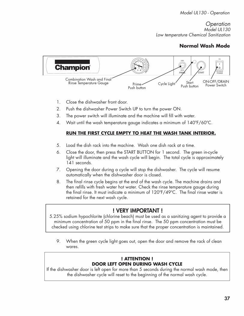
OperationModel UL130
Low temperature Chemical Sanitization
Model UL130 - Operation
Combination Wash and Final Rinse Temperature Gauge Prime
Push buttonCycle Light Start
Push buttonON-OFF/DRAIN
Power Switch
PRIMEOFF/DRAIN
ON
POWERSTART
SANI
RINSE
160
140
120
100
8060
20
170 180
190200
210
220
70 80
95
90
100105 C
F
6050
40
200
NSF
TEMP
ERA
TURE
1. Close the dishwasher front door.2. Push the dishwasher Power Switch UP to turn the power ON.3. The power switch will illuminate and the machine will fill with water.4. Wait until the wash temperature gauge indicates a minimum of 140ºF/60ºC.
RUN THE FIRST CYCLE EMPTY TO HEAT THE WASH TANK INTERIOR.
5. Load the dish rack into the machine. Wash one dish rack at a time.6. Close the door, then press the START BUTTON for 1 second. The green in-cycle
light will illuminate and the wash cycle will begin. The total cycle is approximately 141 seconds.
7. Opening the door during a cycle will stop the dishwasher. The cycle will resume automatically when the dishwasher door is closed.
8. The final rinse cycle begins at the end of the wash cycle. The machine drains and then refills with fresh water hot water. Check the rinse temperature gauge during the final rinse. It must indicate a minimum of 120ºF/49ºC. The final rinse water is retained for the next wash cycle.
9. When the green cycle light goes out, open the door and remove the rack of clean wares.
Normal Wash Mode
! ATTENTION ! DOOR LEFT OPEN DURING WASH CYCLE
If the dishwasher door is left open for more than 5 seconds during the normal wash mode, then the dishwasher cycle will reset to the beginning of the normal wash cycle.
! VERY IMPORTANT ! 5.25% sodium hypochlorite (chlorine beach) must be used as a sanitizing agent to provide a
minimum concentration of 50 ppm in the final rinse. The 50 ppm concentration must be checked using chlorine test strips to make sure that the proper concentration is maintained.
38
Operation - Model UL130
1. Push the illuminated power switch down to the OFF/DRAIN position. The power switch light will go out.
2. The cycle light will illuminate and the machine will drain.3. The machine, will flush, perform 3 short cycles and then drain completely.4. The cycle light will go out indicating that the drain cycle is complete.
OFF/DRAIN
ON
POWER
START
The dishwasher will enter the drain mode whenever the Power Switch is pushed down to the OFF/DRAIN position.
! VERY IMPORTANT ! Draining Problems Related To Improper Installation.
Problems with machine draining are often the result of improper installation. The drain hose is looped and clamped as shown in the photo below and must not be changed.
The drain hose is looped and clamped and must not be changed. Altering the drain hose routing may result in the machine's ability to drain properly.
Drain Mode
39
Cleaning - Model UL130
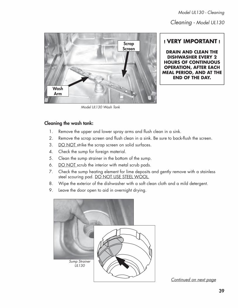
Model UL130 - Cleaning
Model UL130 Wash Tank
Scrap Screen
Wash Arm
Sump Strainer UL130
1. Remove the upper and lower spray arms and flush clean in a sink.2. Remove the scrap screen and flush clean in a sink. Be sure to back-flush the screen.3. DO NOT strike the scrap screen on solid surfaces.4. Check the sump for foreign material.5. Clean the sump strainer in the bottom of the sump.6. DO NOT scrub the interior with metal scrub pads.7. Check the sump heating element for lime deposits and gently remove with a stainless
steel scouring pad. DO NOT USE STEEL WOOL.8. Wipe the exterior of the dishwasher with a soft clean cloth and a mild detergent.9. Leave the door open to aid in overnight drying.
! VERY IMPORTANT !
DRAIN AND CLEAN THE DISHWASHER EVERY 2
HOURS OF CONTINUOUS OPERATION, AFTER EACH
MEAL PERIOD, AND AT THE END OF THE DAY.
Cleaning the wash tank:
Continued on next page

40
Cleaning - Model UL130
Cleaning the wash arms:
Cleaning - Model UL130 (continued)
1. There are two combination wash/rinse arms in the wash tank. They are interchangeable. 2. The wash arms are should be removed and thoroughly flushed clean in a sink.3. Special attention should be paid to the cleaning and inspection of the wash arm
bearings making sure they are clean and free of excessive wear.4. If the bearings are damaged, contact an authorized service agent for replacement.
Model UL130 Clean the upper and lower wash arm bearings.

41
Model UL130 - De-liming
Model UL130 De-liming
DANGER:Death or serious injury may result when de-liming solution is mixed with sodium hypochlorite sanitizing agent. Mixing may cause hazardous gases to form. De-liming solution and other acids must never be mixed with chlorine, iodine, bromine, or fluorine.
CAUTION:Skin contact with de-liming solutions can cause severe irritation and possible chemical burns. Always wear eye protection, rubber gloves and protective clothing when handling chemicals.
! VERY IMPORTANT !
CONTACT YOUR CHEMICAL SUPPLIERFOR THE PROPER DELIMING CHEMICALS.
FOLLOW YOUR CHEMICAL SUPPLIER'S INSTRUCTIONS MAKING SURE
TO WEAR ALL NECESSARY PROTECTION INCLUDING EYE PROTECTION, RUBBER GLOVES AND PROTECTIVE CLOTHING
WHEN HANDLING CHEMICALS.

42
Troubleshooting and Maintenance - Model UL130
Daily Maintenance
1. Make sure the water supply is on and that the drain is not clogged.2. Check the temperature gauges and/or displays to ensure they are operating.3. Make sure the dish racks are in good condition.4. Check the chemical containers and refill as required.5. Follow the cleaning procedures provided in the UL130 Cleaning Section.
Weekly Maintenance
1. Perform Steps 1-5 in the Daily Maintenance.2. Inspect water lines for leaks.3. Check for water leaks underneath the dishwasher.4. Make sure the flexible water fill and drain hoses are not kinked. 5. Make sure that the dishwasher is level.6. Clean accumulated lime deposits from the wash tank heating element.7. Inspect the scrap screen and replace it if damaged.8. Check the spray arms and replace or repair if damaged.
Monthly Maintenance
1. Perform the Daily and Weekly Maintenance listed above.2. Clean the chemical dispenser pick-up tubing for the chemical dispensing pumps.
To clean the pick-up tubing:1. Remove the pick-up tubes from their containers.2. Place each tube in a separate container of hot water.3. Press and hold the PRIME buttons UP and DOWN until water flows into the wash tank
compartment.4. Return the pick-up tubes to their containers.5. Run 3 empty dishwasher cycles to flush any chemicals from the dishwasher wash
compartment.6. Return the pick-up tubes to their containers and prime the chemical lines.
Follow the maintenance schedules below to keep the dishwasher operating most efficiently.
NOTE:There are no lubrication points on the dishwasher.
! ATTENTION !Refer to page 26 for Troubleshooting Instructions.

43
Service Replacement Parts
Service Replacement Parts
Illustrations Page
Wash Pump and Motor Assembly - All Models ......................................................................44
Wash Tank, Lower Piping and Drain Assembly - All Models ....................................................46
Main Terminal Block and Timer Board Assembly - All Models..................................................50
Center Bracket Assembly - All Models ..................................................................................52
Booster Assembly - UH130B, UH230B ................................................................................54
Fill Piping Assembly - UH230, UH230B ...............................................................................56
Upper Final Rinse Piping - UH230, UH230B ........................................................................58
Wash and Rinse Spray Arm Assemblies - UH230, UH230B ...................................................60
Fill Piping Assembly - UH130, UH130B, UL130 ....................................................................62
Fill Solenoid Valve Assembly - UH130, UH130B, UL130 .......................................................64
Fill Chute Assembly - UH130, UH130B, UL130 ....................................................................66
Wash/Rinse Spray Arm Assemblies - UH130, UH130B, UL130 ..............................................68
Detergent Pump Assembly - UH130, UH130B, UH230, UH230B, UL130 ................................70
Rinse-Aid Pump Assembly UH-230, UH230B ........................................................................72
Rinse-Aid Pump Assembly - UH130, UH130B, UL130 ............................................................74
Sanitizer Pump Assembly - UL130 .......................................................................................76
Control Panel - UH230, UH230B ........................................................................................78
Control Panel - UH130, UH130B ........................................................................................80
Control Panel - UL130 .......................................................................................................82
Panel Assembly - All Models ...............................................................................................84
Door Assembly - All Models ................................................................................................86
Dish Racks, Line Strainer, and Pressure Regulating Valve (PRV) ................................................88

44
Wash Pump/Motor Assembly - All Models
1
2
63
45
7 98
10 11
12
13

45
Item Part Description Qty. No. No.
1 0512340 SCREW, M4, PHIL, PAN HD. 9
2 0512341 VOLUTE, PUMP 1
3 114144 NUT, M6 1
4 0501501 WASHER, LOCK, 1/4" 1
5 0501478 WASHER, PLAIN, 17/64" 1
6 0512345 IMPELLER 1
7 114139 SEAL 1 8 110285 GASKET 9
9 114137 BACKPLATE, PUMP 1
10 107337 NUT, M4 9
11 0512101 PUMP/MOTOR ASSEMBLY COMPLETE 1 115VAC/60/1
12 0513131 COVER, REAR MOTOR FAN 1
13 0512347 CAPACITOR 40µF 1
All Models - Wash Pump/Motor Assembly

46
Wash Tank, Lower Piping and Drain Assembly - All Models
To upperwash Manifold
UH230, UH230BTo drain
To drainUH130, UH130B
UL130
UH230, UH230BOnly
UH130,UH130B, UH230,UH230B
UL130Only
UL130Only
UH130,UH130B, UH230,UH230B
UH230, UH230BOnly
2
1
3
46 7
8
9 10
17
13
18
5
14
15
21
37
19
22
26
363735
25
24
25 28
29
1112
37
20
34
32
3031
27
23
27
27
16
16
33

47
Item Part Description Qty. No. No.
All Models - Wash Tank, Lower Piping and Drain Assembly
1 0512136 SCREEN, SCRAP ASSY. 1 2 0712236 TUBE, OVERFLOW GUARD (UH230, UH230B ONLY) 1 3 0512107 THERMOMETER, WASH TANK 1 (UL130 Only)
4 0508872 ADAPTOR, THERMOMETER 1 (UL130 Only) 5 0512099 O-RING 1
6 201029-1 NUT, LOCK 1/2 INCH NI PLATED 2
7 0512169 HEATER, 120VAC 750W (120v LOW TEMP) 1 (UL130) --- 0512426 HEATER, 240VAC 2000W (UH130, UH130B, UH230, UH230B) 1 8 D540088 FLANGE, PUMP SUCTION 1
9 110562 THERMOSTAT, BI-METAL SNAP, 240°F 1
10 UL130 THERMOSTAT ASSEMBLY: - 0507323 THERMOSTAT. WASH TANK 1
- 0512099 O-RING 1
- 0508873 ADAPTOR, THERMOSTAT 1
11 UH130, UH130B, UH230, UH230B TANK PLUG ASSEMBLY: - 108417 NUT, PLUG 1/2" PLASTIC 1
- 108418 PLUG, 1/2" PLASTIC 1
- 109034 WASHER, FIBER 1 12 D80208 GASKET, PUMP SUCTION 1
13 D500603 ELBOW, PUMP SUCTION 1
14 D80305 GASKET, ELBOW 1
15 108447 CAP, 1-1/4" PLASTIC 1
16 0512185 BOLT, HEX FLANGE 1/4-20 X 3/8" SST 2
48
All Models - Wash Tank, Lower Piping and Drain Assembly
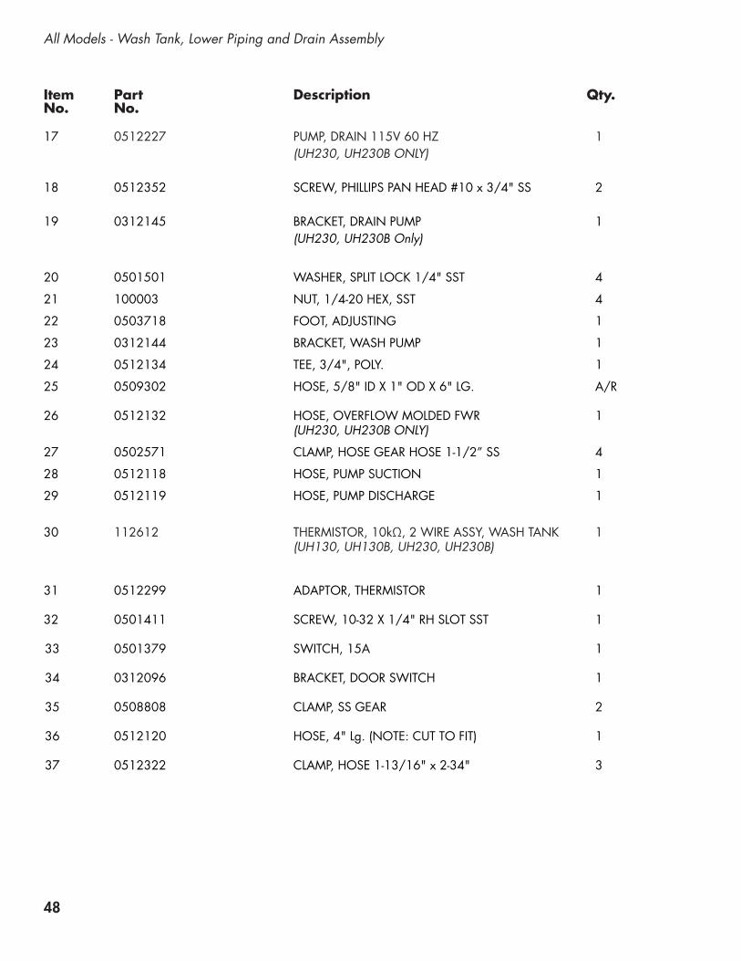
17 0512227 PUMP, DRAIN 115V 60 HZ 1 (UH230, UH230B ONLY)
18 0512352 SCREW, PHILLIPS PAN HEAD #10 x 3/4" SS 2 19 0312145 BRACKET, DRAIN PUMP 1 (UH230, UH230B Only)
20 0501501 WASHER, SPLIT LOCK 1/4" SST 4
21 100003 NUT, 1/4-20 HEX, SST 4
22 0503718 FOOT, ADJUSTING 1
23 0312144 BRACKET, WASH PUMP 1
24 0512134 TEE, 3/4", POLY. 1
25 0509302 HOSE, 5/8" ID X 1" OD X 6" LG. A/R
26 0512132 HOSE, OVERFLOW MOLDED FWR 1 (UH230, UH230B ONLY)
27 0502571 CLAMP, HOSE GEAR HOSE 1-1/2” SS 4
28 0512118 HOSE, PUMP SUCTION 1
29 0512119 HOSE, PUMP DISCHARGE 1
30 112612 THERMISTOR, 10kΩ, 2 WIRE ASSY, WASH TANK 1 (UH130, UH130B, UH230, UH230B)
31 0512299 ADAPTOR, THERMISTOR 1
32 0501411 SCREW, 10-32 X 1/4" RH SLOT SST 1
33 0501379 SWITCH, 15A 1
34 0312096 BRACKET, DOOR SWITCH 1
35 0508808 CLAMP, SS GEAR 2
36 0512120 HOSE, 4" Lg. (NOTE: CUT TO FIT) 1
37 0512322 CLAMP, HOSE 1-13/16" x 2-34" 3
Item Part Description Qty. No. No.

49
Blank Page
This Page Intentionally Left Blank

50
2
1
4
5
8
9
8
16
19
17
20
15
14
6
3
13
10
18
4
Try replacing the 4 Amp fuse before
replacing the circuit bd.7
1112
Main Terminal Block and Timer Board Assembly - All Models

51
Item Part Description Qty. No. No.
All Models - Main Terminal Block and Timer Board Assembly
1 0503574 BUSHING, STRAIN RELIEF, SMALL 3
2 0312188 BASE, TIMER ENCLOSURE 1
3 0508710 SPACER, 5/16" 6
4 0501411 SCREW, 10-32 X 1/4" RH SLOT SS 3
5 0312189 COVER, TIMER ENCLOSURE 1
6 0512243 LABEL, ADJUSTMENT 1
7 0712105 TIMER CKT. BD. , SOLID STATE 1
8 0512373 FUSE, 4A 250VAC, 1
9 106695 SCREW, 6-32 X 1/2" ROUND HD PHI 6
10 0503647 BUSHING, STRAIN RELIEF, MEDIUM 2
11 0501533 NUT, BRASS 10-32 2
12 0501472 WASHER, FLAT 1/8" X 1/2" BRASS 1
13 0501493 WASHER LOCK #10 EXT. TOOTH, BRASS 1
14 0312338 BASE, ENCLOSURE, ELEC. CONN 1
15 0501403 SCREW, BRASS RH 10-32 X 3/4" SLOT 1
16 0503592 LABEL, GROUND 1
17 100007 SCREW TRUSS SLOT SS 10-32X3/8 2
18 100213 SCREW, 10-32 X 1/4", TRUSS HD. 2
19 0509527 BLOCK, TERMINAL, 4-POLE (UH130 UH130B, UH230, UH230B Only) 1
20 0312339 COVER, ENCLOSURE, ELEC. CONN 1
--- 0501292 CORD AND PLUG, POWER 115VAC 1 (UL130 Only) NOT SHOWN

52
7
8
6
Center Bracket Assemblies - All Models
Models UH130, UH130B UH230, UH230B
Model UL130
1 3
5
2
4
UH230, UH230B
UH130, UH130B

53
Item Part Description Qty. No. No.
All Models - Center Bracket Assembly
1 0512444 LABEL, BOOSTER FILL, FILL-OFF-ON 1
2 0312173-1 BRACKET, CHEMICAL PUMP 1
3 0512432 CONTACTOR, 3-POLE 120V 1 (UH130, UH130B, UH230, UH230B)
4 0501373 SWITCH, 3-POSITION TOGGLE 1
5 0504822 SCREW, 8-32 X 1/2" PAN HD PH SST 8
6 0312173-3 BRACKET, CHEMICAL PUMP, THERMOSTAT 1 (UL130 Only)
7 0507323 THERMOSTAT, WASH TANK 1 (UL130 Only)
8 0501450 SCREW, NIBS RH 6-32 X 3/16 PHIL.SS 4

54
Booster Assembly - UH130B, UH230B
1
1
1
2
2
2
2
3
13
12
3 1113
4
5
7
6
7
8
9
10
FromFill Valve
To Rinse

55
Item Part Description Qty. No. No.
UH130B, UH230B - Booster Assembly
1 107417 HOSE, RUBBER 1/2" ID X .84" OD A/R
2 0503679 CLAMP, SS GEAR-MIN. 5/16" 4
3 112612 THERMISTOR 10 kΩ, 2-WIRE 2
4 0513330 BOOSTER, ELEMENT 5 KW, 40°F RISE 1
--- 0513331 BOOSTER, ELEMENT 9 KW, 70°F RISE 1
5 0513525 O-RING, BOOSTER ELEMENT 1
6 0508817 PLUG, 1/8" 1
7 0512185 BOLT, HEX FLANGE, 1/4-20 X 3/8" SST 2
8 0713333 TANK, BOOSTER SST 1
9 110562 THERMOSTAT, HIGH LIMIT 240°F 1
10 108954 NUT, GRIP 6-32 WITH NYLON INSERT SST 2
11 0512298 BUSHING, REDUCING 1/2" NPT X 1/8" NPT 1
12 0512857 TEE. RINSE THERMOMETER 1
13 0513538 HARNESS, BOOSTER THERMISTOR 2
--- 0513537 HARNESS, WIRING (UH130B NOT SHOWN) 1
--- 0513536 HARNESS, WIRING (UH230B NOT SHOWN) 1

56
Fill Piping Assembly - UH230, UH230B
3
9
2
5
6
8
12
71
4
1
From Hot Water Supply
Note:This is a 3/4”
Garden Hose FItting
11
10

57
Item Part Description Qty. No. No.
1 0503679 CLAMP, SS GEAR-MIN. 5/16" 2
2 0502653 ELBOW, 90° 3/8" MPT X 1/2" HOSE 1
3 0502650 BUSHING, 1/2" NPT X 3/8" NPT 2
4 0312146 BRACKET, 1/2" SOLENOID VALVE 1 (UH230, UH230B)
5 0512185 BOLT, HEX FLANGE 1/4-20 X 3/8" SS 2
6 0502618 BARB, HOSE 1/2" X 3/8" MPT 1
7 0509526 HOSE, 1/2" X 7' (3/4" garden hose fitting) 1
8 0505320 WASHER, 1" OD GARDEN HOSE 1
9 109886 VALVE, SOLENOID, 1/2” NPT 120VAC 1
10 109902 KIT, REPAIR, 1/2" SOLENOID VALVE 1
11 108516 KIT, REPAIR, COIL, 120VAC 1
12 107417 HOSE, RUBBER 1/2" ID X .84" OD A/R
UH230, UH230B - Fill Piping Assembly

58
Upper Final Rinse Piping - UH230, UH230B
10
13
8
7
6
32
1
1
45
2
2
12
14
15
1
15
9
11

59
Item Part Description Qty. No. No.
1 107417 HOSE, RUBBER 1/2ID X .84OD AR
2 0503679 CLAMP, SS GEAR-MIN. 5/16-MAX.7/8 6
3 112728 FITT COMP 1/4OD X 1/8MPT ELL J 1
4 0508817 PLUG, 1/8 HEX COUNTERSUNK 1
5 0513110 MANIFOLD, RINSE (UH230, UH230B) 1
6 112763 INJECTOR FITTING 1
7 112883-1 TUBING, 1/8" OD X 1/16" ID AR
8 100003 NUT, HEX SS 1/4-20 2
9 0501501 WASHER, SPLIT LOCK 1/4i 304SS 2
10 0312190 BRACKET, VACUUM BREAKER 1
11 201029 NUT, LOCK 1/2" NICKEL PLATED 1
12 100500 VACUUM BREAKER, 1/2" NPT, BRONZE 1
13 900836 REPAIR KIT, VACUUM BREAKER 1/2" 1
14 0502651 COUPLER 1/2 MPT X 1/2" HOSE 1
15 107928 TUBING, 1/4" NATURAL AR
UH230, UH230B - Upper Final Rinse Piping

60
Wash and Rinse Spray Arm Assemblies - UH230, UH230B
13
13
15
18
16
16 16
17
20
19
21
11
7
7
23 24
26
28
29
30
27
2522
6
31
1
23
45
6
10
11
12
12
8 9
14

61
Item Part Description Qty. No. No.
1 0501478 WASHER, 17/64 id X 9/16" OD SST 4
2 107967 NUT, HEX 1/40-20 NYLON INSERT SST 4
3 H35509 HUB, UPPER SPRAY ARMS 1
4 107873 WASHER, PACKING 1
5 110215 PLUG, UPPER MANIFOLD 1
6 0502571 CLAMP, HOSE GEAR 1-1/2" SST 2
7 0512120 HOSE, UPPER WASH ARM 1
8 0512133 O-RING, 2-1/8" OD X 1-3/4" ID X 3/16" 1
9 0501481 WASHER, NYLITE 4
10 100738 BOLT, 1/4-20 X 1" SST 4
11 H420548 WASH ARM ASSEMBLY (Includes Item 12) 2
12* 0712749 BEARING ASSEMBLY 2
13 H34998 NUT, SPACER 2
14 H36211 RINSE ARM ASSEMBLY (Includes Items 13, 16, and 17) 2
15 H37149 NOZZLE, RINSE ARM 12
16 H190663 BEARING, RINSE ARM 4
17 H36275 SPINDLE, RINSE ARM 2
18 0512124 SHAFT, LOWER 1
19 0512066 HUB, LOWER WASH ARM 1
20 0512133 O-RING, 2-1/8" OD X 1-3/4" ID X 3/16" 1
21 0512102 MANIFOLD, LOWER FWR 1
22 100007 SCREW, TRUSS SLOT 10-32 X3/8" SST 1
23 0512127 GASKET, DRAIN 1
24 0512104 FLAP, DRAIN 1
25 100194 NUT, GRIP 10-32 SST 1
26 0512126 SPRING, TORSION 1
27 0512130 O-RING, DRAIN SHAFT 1
28 0512128 SHAFT, DRAIN 1
29 0712123 MOTOR, DRAIN 115VAC 1
30 104883 SCREW, 6-32 X 3/8" RD. HD. SLOTTED, SST 2
31 0512239 O-RING 1
---- 0712368 DRAIN MANIFOLD ASSEMBLY (Includes Items 20-29) 1
* Note: The bearing assembly, P/N 0712749 includes 2 bearings, 1 locknut, and 1 wash arm hub. The bearings, locknut and hub are not available as separate service replacement parts.
UH230, UH230B - Wash and Rinse Spray Arm Assemblies

62
Fill Piping Assembly - UH130, UH130B, UL130
1
3
4
5 6
7
8
2
2
2
6
9
Note:This is a 3/4"garden hose fitting From Hot Water
Supply
To Booster InletUH130B
Fill Valve Assembly on Next Page
To Fill ChuteUH130, UL130

63
Item Part Description Qty. No. No.
1 0502653 ELBOW, 90 DEGR 3/8" MPT X 1/2" HOSE 1
2 0512185 BOLT, HEX FLANGE 1/4-20 X 3/8" SS 4
3 0300065 SUPPORT, VALVE 1
4 0300203 CLAMP, VALVE 1
5 0502618 HOSE BARB, 1/2" X 3/8" MPT 1
6 0503679 CLAMP, SS GEAR-MIN. 5/16"- MAX. 7/8" 1
7 0509526 HOSE, 1/2" X 7 FT. FEM. GARD. ADAPT. 1
8 0505320 WASHER, 1” O.D. GARDEN HOSE 1
9 0504952 VALVE, FILL, 3/8" NPT 1
UH130, UH130B, UL130 - Fill Piping Assembly
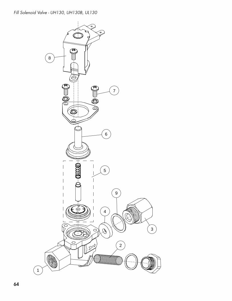
64
Fill Solenoid Valve - UH130, UH130B, UL130
1
2
3
4
9
5
6
7
8

65
Item Part Description Qty. No. No.
1 0504952 VALVE, FILL 5.0 GPM 1
2 0502803 SCREEN, SOL-VALVE STRAINER 1
3 0502804 GASKET, CAP 1
4 0504958 WASHER, FLOW 5.0 GPM 1
5 0502811 KIT, REBUILD 1 6 0505229 GUIDE 1
7 0501406 SCREW, SLOT SS RH 8-32 X 1/2" 3
8 0505235 COIL, 115V 60HZ 10W 1
9 0502807 GASKET, OUTLET (COPPER) 1
UH130, UH130B, UL130 - Fill Solenoid Valve

66
From Booster (UH130B)or
Fill Valve (UH130, UL130)
From Rinse AidPump
FromDetergentPump
5
54
32
8
1
6
5 5
1
From SanitizerPump
9
10
10
7
Fill Chute Assembly - UH130, UH130B, UL130

67
Item Part Description Qty. No. No.
1 106090 TIE PLATE 2
2 0509048 GASKET, INLET CHUTE 1
3 0508867 CHUTE, INLET 1
4 0507709 WASHER, FLAT #10 SS 4
5 0503722 NUT, HEX 10-32 SS 6
6 0502666 HOSE, 1/8" ID X 1/4" OD PVC AR
7 0502667 HOSE, 1/4" ID X 3/8" OD PVC AR 8 0308822 CLIP, HOSE 1
9 107417 HOSE, RUBBER 1/2" ID X .84" OD AR
10 0501518 TIE, NYLON 5-1/2" 2
UH130, UH130B, UL130 - Fill Chute Assembly

68
Wash/Rinse Spray Arm Assembly - UH130, UH130B, UL130
1
23
45
6 7
109
13
17
11
6
14
12
12
8
11
15
1620
21
23
25
26
24
22
1819

69
Item Part Description Qty. No. No.
1 0501478 WASHER, 17/64" IDX 9/16" OD SST 4
2 107967 NUT, HEX SST 1/4-20 NYLON INSERT 4
3 H35509-1 HUB, UPPER WASH ARM 1
4 107873 WASHER, PACKING 1
5 110215 SCREW, RETAINING 1
6 0502571 CLAMP, HOSE GEAR HOSE 1-1/2” SST 2
7 0512120 HOSE, UPPER WASH ARM 1
8 0512133 O-RING, 2-1/8" OD X 1-3/4" ID X 3/16 1
9 100738 BOLT, 1/4-20 X 1" HEX. HD. SST 4
10 0501481 WASHER, NYLTITE 4
11 H420548 WASH ARM ASSEMBLY (Includes Item 12) 2
12* 0712749 BEARING ASSEMBLY 2
13 0512129 NUT, WASH ARM 2
14 0512125 SHAFT, LOWER 1
15 0512066 HUB, LOWER WASH ARM 1
16 0512133 O-RING, 2-1/8" OD X 1-3/4" ID X 3/16 1
17 0512103 MANIFOLD, LOWER 1
18 100007 SCREW, TRUSS SLOT 10-32 X3/8" SST 1
19 0512127 GASKET, DRAIN 1
20 0512104 FLAP, DRAIN 1
21 100194 NUT, GRIP 10-32 SST 1
22 0512126 SPRING, TORSION 1
23 0512130 O-RING, DRAIN SHAFT 1
24 0512128 SHAFT, DRAIN 1
25 0712123 MOTOR, DRAIN 115VAC 1
26 104883 SCREW, 6-32 X 3/8 RD. HD. SLOTTED, SST 2
---- 0712367 DRAIN MANIFOLD ASSEMBLY (Includes Items 16-25) 1
* Note: The bearing assembly, P/N 0712749 includes 2 bearings, 1 locknut, and 1 wash arm hub. The bearings, locknut and hub are not available as separate service replacement parts.
UH130, UH130B, UL130 - Wash/Rinse Spray Arm Assembly

70
Detergent Pump Assembly - UH130, UH130B, UH230, UH230B, UL130
9
8
7
7
6
6
5
6
6
4
3
2
1
5
10
Check the squeeze tube every 6 months for wear.

71
Item Part Description Qty. No. No.
1 0510870-1 GEARMOTOR, 115/60/1 1
2 114203 PUMP HD KIT, PERISTALIC 1
3 114202 TUBE ASY,SANTOPRENE, 3/16" X 3/8" X 9" LG. 1
4 0512369 CLAMP, HOSE 1
5 0502644 ELBOW, 1/4 HOSE BARB 2
6 0501519 TIE, NYLON 4" 4
7 0502667 HOSE, 1/4" ID X 3/8" OD PVC A/R 8 0503695 LABEL, DETERGENT 1 9 0306363 TUBE, 3/8" ID X 12" LG. STIFFENER 1
10 0501869 STRAINER 1
UH130, UH130B, UH230, UH230B, UL130 - Detergent Pump Assembly

72
Rinse-Aid Pump Assembly - UH230, UH230B
3
2
1
5
5
5
9
4
7
8
10
To Injection Point
6
11
Pink Rollers
Check the squeeze tube every 6 months for wear.

73
Item Part Description Qty. No. No.
UH230, UH230B - Rinse-Aid Pump Assembly
1 0510872-1 GEARMOTOR, RINSE-AID 115/60/1 1
2 114203 PUMP HEAD, PERISTALTIC 1
3 112759 TUBE, PUMP 1/8" ID X 9" LG. 1
4 0512369 CLAMP, HOSE 1
5 0501519 TIE, CABLE 4" 4
6 112883-1 TUBING, 1/8" OD X 1/16" ID A/R
7 0505483 LABEL, RINSE AID 1
8 0306363 TUBE, 3/8" ID X 12" LG. STIFFENER 1
9 0512794 CONNECTOR, 5/32" X 1/8" 1
10 0501869 STRAINER 1
11 0502666 TUBING, 1/4" OD X 1/8" ID A/R

74
Rinse-Aid Pump Assembly - UH130, UH130B, UL130
1
4
6
6
8
9
To Fill Chute
10
2
3
5
7
7
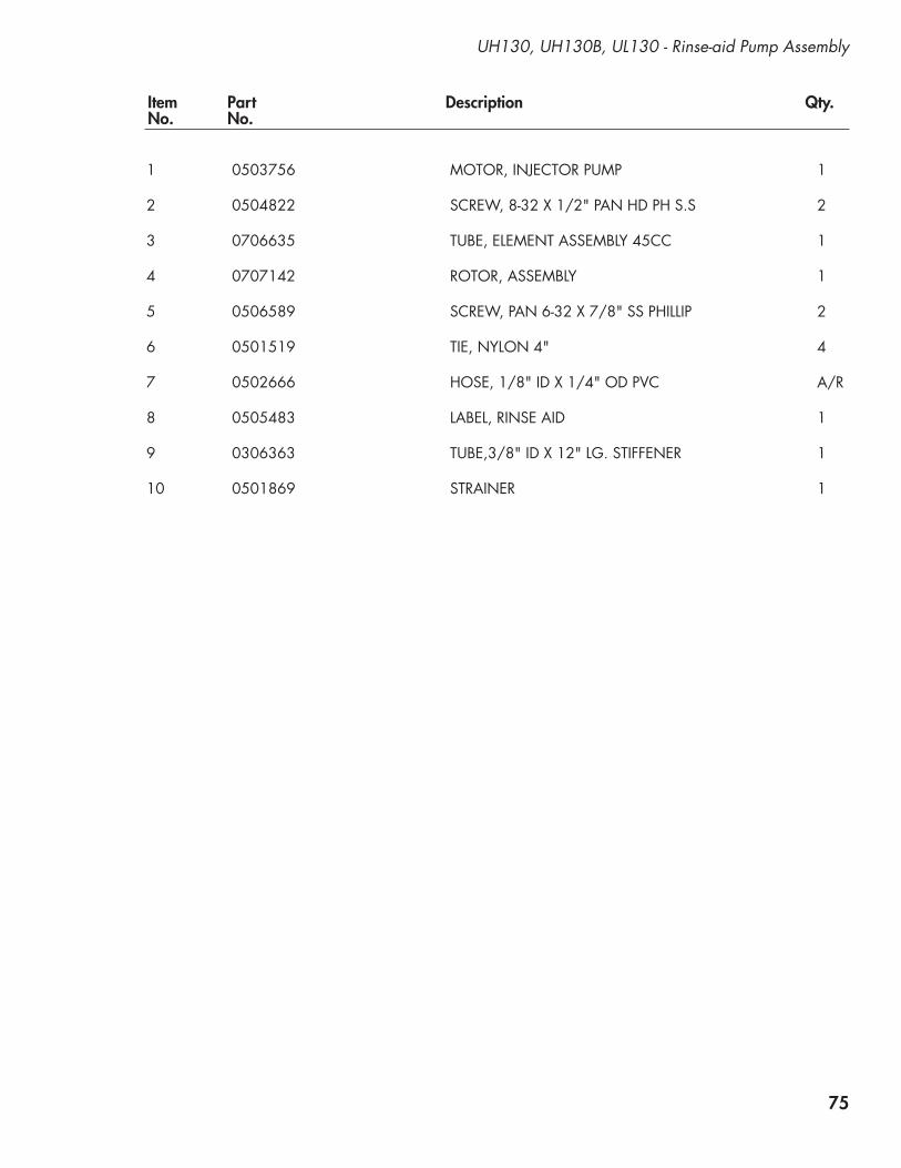
75
Item Part Description Qty. No. No.
1 0503756 MOTOR, INJECTOR PUMP 1
2 0504822 SCREW, 8-32 X 1/2" PAN HD PH S.S 2 3 0706635 TUBE, ELEMENT ASSEMBLY 45CC 1
4 0707142 ROTOR, ASSEMBLY 1
5 0506589 SCREW, PAN 6-32 X 7/8" SS PHILLIP 2
6 0501519 TIE, NYLON 4" 4
7 0502666 HOSE, 1/8" ID X 1/4" OD PVC A/R
8 0505483 LABEL, RINSE AID 1
9 0306363 TUBE,3/8" ID X 12" LG. STIFFENER 1
10 0501869 STRAINER 1
UH130, UH130B, UL130 - Rinse-aid Pump Assembly

76
Sanitizer Pump Assembly - UL130
To Injection Point
11
10

77
Item Part Description Qty. No. No.
UL130 - Sanitizer Pump Assembly
1 0503756 MOTOR, INJECTOR PUMP 1 2 0706635 TUBE, ELEMENT ASSEMBLY 45CC 1
3 0707142 ROTOR, ASSEMBLY 1
4 0501519 TIE, NYLON 4" 4
5 0503694 LABEL, SANITIZER 1
6 0306363 TUBE, 3/8" ID X 12" LG. STIFFENER 1
7 0501869 STRAINER 1
8 0504822 SCREW, 8-32 X 1/2" PAN HD PH S.S 2
9 0506589 SCREW, PAN 6-32 X 7/8" SS PHILLIP 2
10 0502666 HOSE, 1/8" ID X 1/4" OD PVC A/R
11 112759 TUBE, PUMP 1/8" ID X 1/2" LG. 1

78
Control Panel - UH230, UH230B
12
3
3
2
6
5
7
5
108
8
9
9
11
12
12
10
4

79
Item Part Description Qty. No. No.
UH230, UH230B - Control Panel
1 0512221 SWITCH, ROCKER DPST 250V NEON 1
2 0512213 SWITCH, PIEZIO 2
3 0512232 LIGHT, INDICATOR, GREEN 2
4 0512226 SWITCH, ROCKER RND SPDT MOMENTARY 1
5 0501408 SCREW, TRUSS SLOT SS 8-32 X 1/4" 2
6 0512448 LABEL, FACIA 1
7 0312438 PANEL, FACIA 1
8 0512357 STANDOFF, LED DISPLAY BOARD 2
9 0503580 NUT, 10-32 2
10 0501563 SCREW, #8 X 3/8" 4
11 0512106-1 TEMPERATURE INDICATOR BD., DIGITAL 1
12 0512320 GASKET, STEAM 2
--- 0512362 HARNESS, DIGITAL DISPLAY WIRING (Not Shown) 1
-- 0513536 HARNESS, COMPLETE MACHINE (Not Shown)) 1

80
Control Panel - UH130, UH130B
12
3
6
7
10
8
8
9
9
11
12
12
10
4
5
5

81
Item Part Description Qty. No. No.
UH130, UH130B - Control Panel
1 0512221 SWITCH, ROCKER DPST 250V NEON 1
2 0512213 SWITCH, PIEZIO 2
3 0512232 LIGHT, INDICATOR, GREEN 2
4 0512226 SWITCH, ROCKER RND SPDT MOMENTARY 1
5 0501408 SCREW, TRUSS SLOT SS 8-32 X 1/4" 2
6 0513540 LABEL, FACIA 1
7 0312438 PANEL, FACIA 1
8 0512357 STANDOFF, LED DISPLAY BOARD 2
9 0503580 NUT, 10-32 2
10 0501563 SCREW, #8 X 3/8" 4
11 0512106-1 TEMPERATURE INDICATOR BD., DIGITAL 1
12 0512320 GASKET, STEAM 2
--- 0512362 HARNESS, DIGITAL DISPLAY WIRING (Not Shown) 1
-- 0513537 HARNESS, COMPLETE MACHINE (Not Shown)) 1

82
Control Panel - UL130
7
9
8
3
6
12
4
7
5
5

83
Item Part Description Qty. No. No.
UL130 - Control Panel
1 0512220 SWITCH, ROCKER DPST 250V NEON 1 2 0512214 SWITCH, PUSH-BUTTON, GREEN 1
3 0512232 LIGHT, INDICATOR, GREEN 2
4 0512226 SWITCH, ROCKER RND SPDT MOMENTARY 1
5 0512320 GASKET, STEAM 2
6 0512107 THERMOMETER, 2" DIAL, 7" CAPILLARY 1
7 0501408 SCREW, TRUSS SLOT SS 8-32 X 1/4" 2
8 0512453 LABEL, FACIA 1
9 0312440 PANEL, FACIA 1

84
Panel Assembly - All Models
1
5
6
9
11
12
13
15 1617
14
12
2
3
7
7
8
4
9
9
10
9
13
13
1213
12
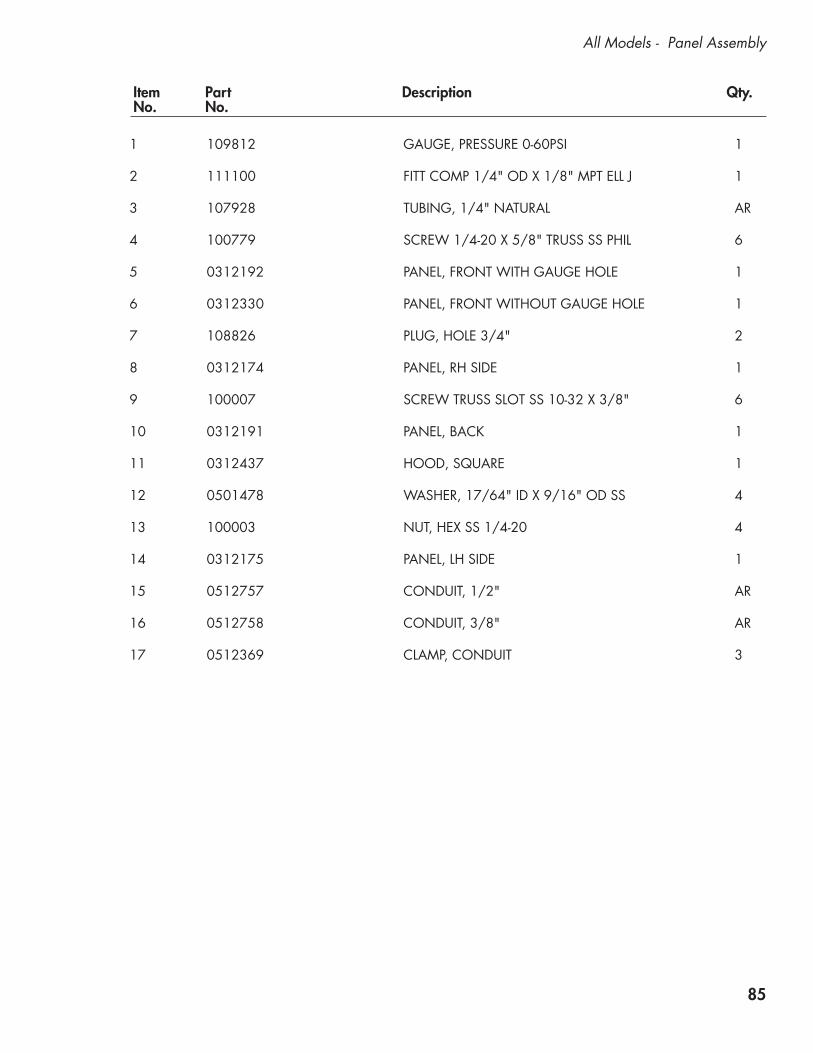
85
Item Part Description Qty. No. No.
All Models - Panel Assembly
1 109812 GAUGE, PRESSURE 0-60PSI 1
2 111100 FITT COMP 1/4" OD X 1/8" MPT ELL J 1
3 107928 TUBING, 1/4" NATURAL AR
4 100779 SCREW 1/4-20 X 5/8" TRUSS SS PHIL 6
5 0312192 PANEL, FRONT WITH GAUGE HOLE 1
6 0312330 PANEL, FRONT WITHOUT GAUGE HOLE 1 7 108826 PLUG, HOLE 3/4" 2 8 0312174 PANEL, RH SIDE 1 9 100007 SCREW TRUSS SLOT SS 10-32 X 3/8" 6
10 0312191 PANEL, BACK 1
11 0312437 HOOD, SQUARE 1
12 0501478 WASHER, 17/64" ID X 9/16" OD SS 4
13 100003 NUT, HEX SS 1/4-20 4
14 0312175 PANEL, LH SIDE 1
15 0512757 CONDUIT, 1/2" AR
16 0512758 CONDUIT, 3/8" AR
17 0512369 CLAMP, CONDUIT 3
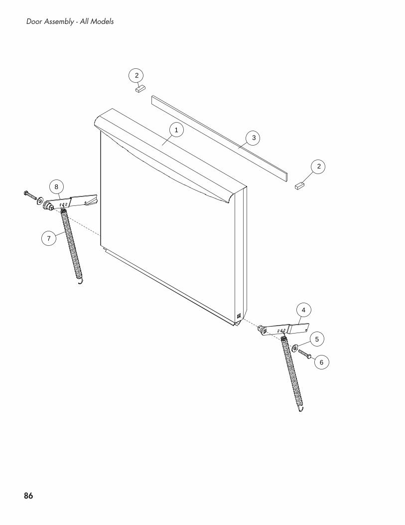
86
Door Assembly - All Models
13
4
5
6
7
8
2
2

87
Item Part Description Qty. No. No.
All Models - Door Assembly
1 0713136 DOOR ASSEMBLY 1
2 0512320 GASKET, STEAM 2
3 0512319 GASKET, DOOR (TOP) 1
4 0712162-1 HINGE, RH ASSY 1
5 0501476 WASHER, 9/32" X 5/8" OD SS 1
6 0501422 BOLT, HEX SS 1/4-20 X 1-1/2" 1
7 0512122 SPRING, DOOR 2
8 0712162 HINGE, LH ASSY 1

88
Dish Racks, Line Strainer, PRV
1
2
3
4

89
Item Part Description Qty. No. No.
Dish Racks, Line Strainer, PRV
1 101273 DISH RACK, FLAT-BOTTOM AR 2 101285 DISH RACK, PEG AR
3 104421 STRAINER, LINE 1/2" BRONZE 1 (UH230, UH230B)
4 108265 VALVE, PRESSURE REGULATING (PRV) 1 (UH230, UH230B)
90
This Page Intentionally Left Blank
Blank Page

91
Electrical Schematics
Electrical Schematics and Timing Charts
Illustrations Page
Low Temperature Model - UL130 ........................................................................................92
High Temperature Models - UH130, UH130B, UH230B, UH230B .........................................93
Timing Charts ..................................................................................................................94

92
UL130 - Low Temperature Undercounter
Electrical Schematic - UL130

93
Electrical Schematic - UH130, UH130B, UH230, UH230B
SINGLE PHASE THREE PHASE
4 A
MP
FU
SE
UH130, UH130B, UH230, UH230B - Digital DisplayHigh Temperature Undercounter

94
Tim
ing
Cha
rt fo
r UH
230,
UH
230B
Tim
ing
Cha
rt fo
r UH
130,
UH
130B
, UL1
30
Timing Charts

95
Basic Service
Basic Service
Illustrations Page
Booster/Wash Tank Heater Interlock Circuit Operation - UH130B, UH230B ................96
Digital Temperature Display Board - UH130, UH130B, UH230, UH230B ...................97
Digital Temperature Display Codes - UH130, UH130B, UH230, UH230B ................101
Timer Board Connection Diagram - All Models ......................................................104
Timer Board Troubleshooting Guide - All Models ....................................................105
Timer Board Diagnostic Testing - All Models...........................................................106
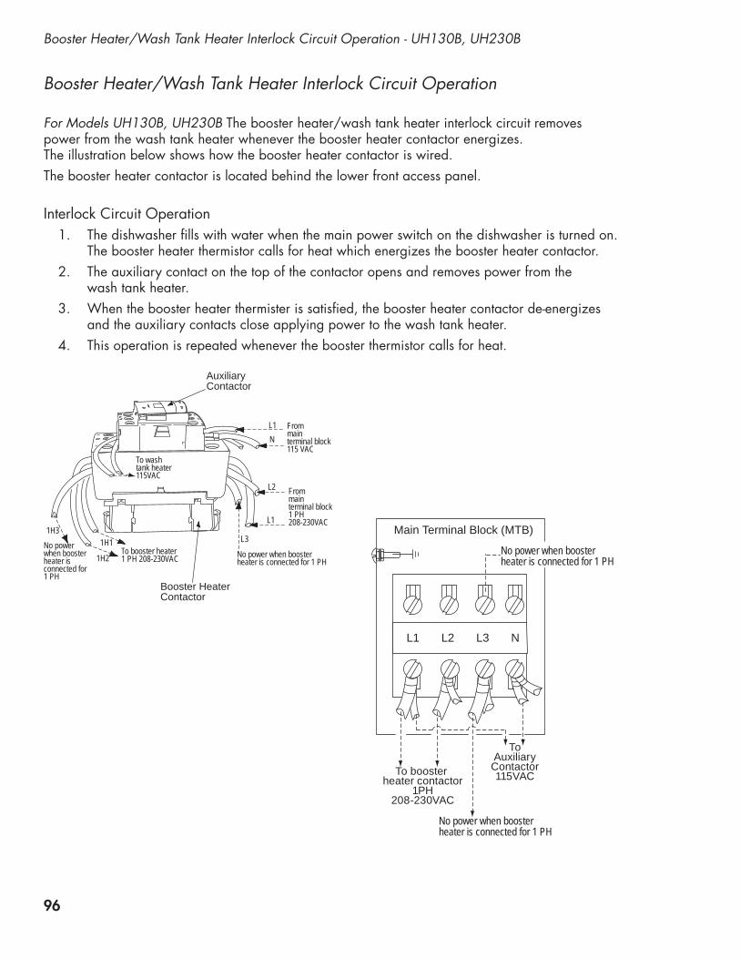
96
Booster Heater/Wash Tank Heater Interlock Circuit Operation - UH130B, UH230B
Booster Heater/Wash Tank Heater Interlock Circuit Operation For Models UH130B, UH230B The booster heater/wash tank heater interlock circuit removes power from the wash tank heater whenever the booster heater contactor energizes. The illustration below shows how the booster heater contactor is wired. The booster heater contactor is located behind the lower front access panel.
Interlock Circuit Operation1. The dishwasher fills with water when the main power switch on the dishwasher is turned on.
The booster heater thermistor calls for heat which energizes the booster heater contactor. 2. The auxiliary contact on the top of the contactor opens and removes power from the
wash tank heater.3. When the booster heater thermister is satisfied, the booster heater contactor de-energizes
and the auxiliary contacts close applying power to the wash tank heater. 4. This operation is repeated whenever the booster thermistor calls for heat.
To booster heater contactor
1PH208-230VAC
ToAuxiliaryContactor115VAC
No power when boosterheater is connected for 1 PH
No power when boosterheater is connected for 1 PH
L1 L2 L3 N
Main Terminal Block (MTB)
To wash tank heater115VAC
From main terminal block115 VAC
From main terminal block1 PH208-230VAC
No powerwhen boosterheater isconnected for1 PH
No power when boosterheater is connected for 1 PH
L1
L3
L1N
L2
To booster heater1 PH 208-230VAC1H2
1H31H1
Auxiliary Contactor
Booster HeaterContactor

97
UH130, UH130B, UH230, UH230B - Digital Temperature Display Board
Und
erco
unte
r Tem
pera
ture
Dis
play
Boa
rd U
pdat
es —
P/N
051
2106
1.
The
new
ver
sion
for t
he u
nder
coun
ter d
ispl
ay b
oard
is la
rger
than
the
disp
lay
boar
d us
ed o
n pr
evio
us m
odel
s.
2.
The
new
ver
sion
boa
rd m
ount
ing
hole
s ar
e in
the
sam
e lo
catio
n as
the
old
boar
d an
d w
ill m
ount
in th
e m
achi
ne a
s be
fore
.
Old
Ver
sion
of T
empe
ratu
re D
ispl
ay B
oard
New
Ver
sion
of T
empe
ratu
re D
ispl
ay B
oard
Mou
ntin
g ho
les
are
in th
e sa
me
loca
tions
for i
nsta
llatio
n

98
Digital Temperature Display Board - UH130, UH130B, UH230, UH230B
Undercounter Tem
perature Display Board —
P/N 0512106
M3 - M
4 Model Selector Slide Sw
itch
M4
M3
! ATTENTIO
N —
VERY IM
PORTA
NT !
Before installing a new version display board,
you must select the m
odel type using theM
3 - M4 Sw
itch located at the bottom center
of the circuit board.
M3 Setting
Slide the selector switch to the M
3 positionfor m
achines equipped with therm
ostats.
M4 Setting
Slide the selector switch to the M
4 positionfor m
achines equipped with therm
istors only.
NO
TE:The m
achine will not operate properly if the
selector switch is set to the w
rong position.

99
Und
erco
unte
r Tem
pera
ture
Dis
play
Boa
rd
P/N
051
2106
BRi
nse
Test
Push
butto
n
AW
ire H
arne
ss P
lug
for W
ash
and
Rins
eTh
erm
isto
rsC
Was
h Te
stPu
shbu
tton
DBo
oste
rTe
mpe
ratu
reA
djus
tM
4SE
TTIN
GO
NLY
EW
ash
Tem
pera
ture
Adj
ust
M4
SETT
ING
ON
LY
Dia
gnos
tics
A -
Whe
n te
sting
the
circ
uit b
oard
oper
atio
n, d
isco
nnec
t the
har
n-
ess
from
this
plu
g. T
he w
ash
and
rin
se d
ispl
ays
will
dis
play
E.
B -
Push
and
hol
d th
e rin
se te
st
push
butto
n. A
num
eric
al v
alue
of
179
-180
sho
uld
appe
ar
in th
e rin
se te
mpe
ratu
re d
ispl
ay
win
dow
indi
catin
g th
e ci
rcui
t
boar
d is
ope
ratin
g no
rmal
ly.
C -
Push
and
hol
d th
e w
ash
test
pu
shbu
tton
for 1
0 se
cond
s
A n
umer
ical
val
ue o
f 140
sh
ould
app
ear i
n th
e w
ash
te
mpe
ratu
re d
ispl
ay w
indo
w
indi
catin
g th
e ci
rcui
t boa
rd
is
ope
ratin
g no
rmal
ly.
Whe
n pe
rform
ing
diag
nosti
cs th
e va
lues
are
disp
laye
d in
°F
even
if th
e di
spla
y is
set
for °
C.
A F
/C S
lide
switc
h is
pro
vide
d on
the
boar
dto
cha
nge
the
disp
lay
from
the
fact
ory
defa
ult
setti
ng o
f °F
to th
e op
tiona
l °C
.
D -
Turn
clo
ckw
ise
to in
crea
se th
e
boos
ter t
empe
ratu
re. F
ull r
ange
is
3/4
turn
s 18
0-20
0°F.
DO
NO
T FO
RCE
PAST
TH
E ST
OPS
.
E -
Turn
clo
ckw
ise
to in
crea
se th
e
was
h te
mpe
ratu
re. F
ull r
ange
is
3/
4 tu
rns
120-
160°
F. D
O N
OT
FO
RCE
PAST
TH
E ST
OPS
.
Tem
pera
ture
Adj
ustm
ents
UH130, UH130B, UH230, UH230B - Digital Temperature Display Board

100
Digital Temperature Display Board - UH130, UH130B, UH230, UH230B
Undercounter Tem
perature Display Board —
P/N 0512106
Power Term
inals.
Power Neutral
Wash
Heater
IN
Wash
Heater O
UT
Booster IN
Fuse 20ABooster OU
T
A120VA
C input
for display board
B120VA
C input
for booster control
C240VA
C input
for wash tank heater
D20 A
mp fuse
for wash tank heater
E240VA
C output
to wash tank heater
F120VA
C ouput
to booster contactor coil
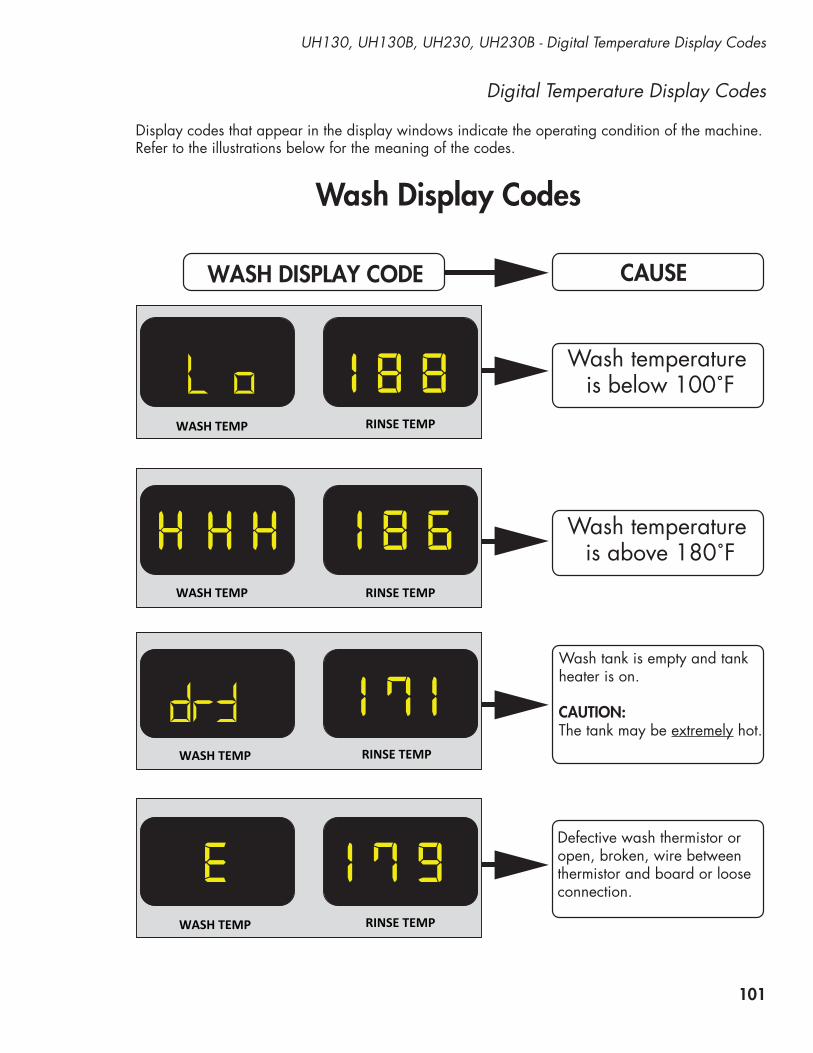
101
UH130, UH130B, UH230, UH230B - Digital Temperature Display Codes
Digital Temperature Display Codes
Display codes that appear in the display windows indicate the operating condition of the machine. Refer to the illustrations below for the meaning of the codes.
WASH DISPLAY CODE
WASH TEMP RINSE TEMP
WASH TEMP RINSE TEMP
RINSE TEMP
RINSE TEMP
WASH TEMP
WASH TEMP
1 8 8L o
H 1 8 6
1 7 1
E 1 7 9
HH
drY
Wash Display Codes
CAUSE
Wash temperature is below 100˚F
Wash temperature is above 180˚F
Wash tank is empty and tankheater is on.
CAUTION:The tank may be extremely hot.
Defective wash thermistor oropen, broken, wire betweenthermistor and board or looseconnection.
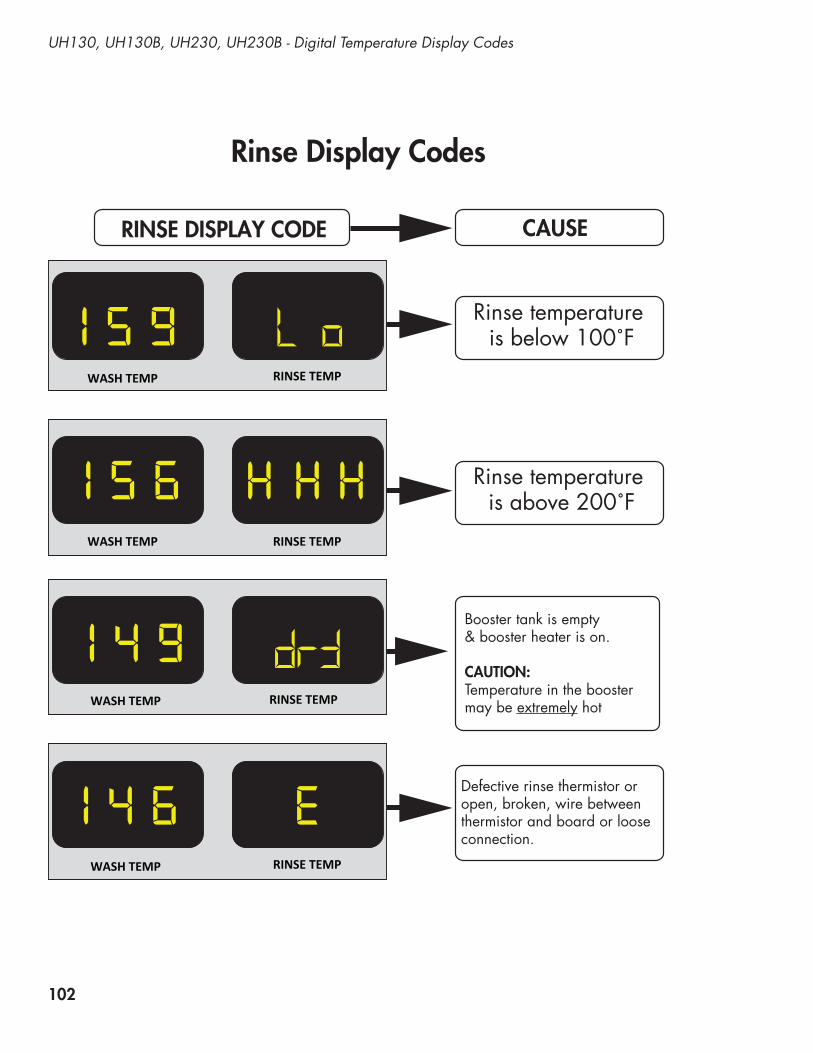
102
UH130, UH130B, UH230, UH230B - Digital Temperature Display Codes
RINSE DISPLAY CODE
WASH TEMP RINSE TEMP
WASH TEMP RINSE TEMP
RINSE TEMP
RINSE TEMP
WASH TEMP
WASH TEMP
1 5 9 L o
1 5 6
1 4 9
E1 4 6
H HH
drY
Rinse Display Codes
CAUSE
Rinse temperature is below 100˚F
Rinse temperature is above 200˚F
Booster tank is empty& booster heater is on.
CAUTION:Temperature in the boostermay be extremely hot
Defective rinse thermistor oropen, broken, wire betweenthermistor and board or looseconnection.

103
UH130, UH130B, UH230, UH230B - Digital Temperature Display Codes
DISPLAY CODES
WASH TEMP RINSE TEMP
WASH TEMP RINSE TEMP
RINSE TEMPWASH TEMP
b E
b E E
b
Booster Display Codes
CAUSE
Booster overtemp lockoutbecause booster temperatureis greater than 210˚F.
NOTE: Booster is locked outfor 10 minutes before beingre-energized.
Booster therrmistor is defective or disconnected,broken wires.
NOTE: After the therrmistoris reconnected, there is a 5 second delay before the display is re-energized.
Error Codes for Booster and Final Rinse Thermistors Only.
1 5 0
1 5 0
1 5 0Both booster and final rinsedisplay thermistors aredefective, unplugged, or openor broken wires between thedisplay and thermistor.
NOTE: After a therrmistoris reconnected, there is a 5 second delay before the display is re-energized.
H

104
Timer Board Connection Diagram - All Models
Timer C
onnection Diagram
Solid S
tate Timer P
/N 0512105
January 2009
RE
BO
OT A
FTER
MO
DE
L SE
LEC
TION
OUTPUT SANITIzER
wASH MOTOR OUTPUT
OUTPUT RINSE AID
OUTPUT DETERgENT
OUTPUT FILL vALvE
DRAIN vALvE OPEN
DRAIN vALvE CLOSED
LOw vOLTAgE PLUg• START SwITCH• SCRUB SwITCH• CYCLE LIgHT• SCRUB LIgHT
HO
T 115v
NE
UTR
AL
PO
wE
R
IN
FRO
M O
N/O
FF Sw
ITCH
RIN
SE
SE
NTR
Y FRO
M
BO
OS
TER
CONTR
OL
SK
IP TO N
EX
TS
EQ
UE
NC
E O
F CY
CLE
4 AMP CONTROL FUSE
DIP
Sw
ITCH
Select appropriate setting for model of m
achine Fw
R- M
OD
EL U
H230, U
H230B
F&D
- MO
DE
L UH
130, UH
130B, U
L130
0512934
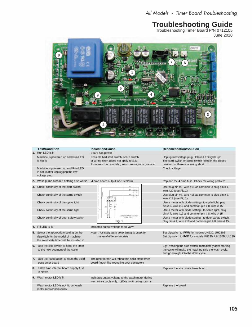
105
All Models - Timer Board Troubleshooting
Test/Condition Indication/Cause Recomendation/Solution1. Run LED is lit Board has power Machine is powered up and Run LED Possible bad start switch, scrub switch Unplug low voltage plug. If Run LED lights up: is not lit or wiring short (does not apply to S.S. The start switch or scrub switch failed in the closed
Pizio switch on models (UH130, UH130B, UH230, UH230B) position, or there is a wiring short Machine is powered up and Run LED Check voltage is not lit after unplugging the low voltage plug
2. Wash pump runs but nothing else works 4 amp board output fuse is blown Replace the 4 amp fuse. Check for wiring problem
3. Check continuity of the start switch Use plug pin #8, wire #15 as common to plug pin # 1,wire #20 (see Fig.1)
Check continuity of the scrub switch Use plug pin #8, wire #15 as common to plug pin # 3,wire #19 (see Fig.1)
Check continuity of the cycle light Use a meter with diode setting - to cycle light, plug pin # 6, wire #16 and common pin # 8, wire # 15
Check continuity of the scrub light Use a meter with diode setting - to scrub light, plug pin # 7, wire #17 and common pin # 8, wire # 15
Check continuity of door safety switch Use a meter with diode setting - to door safety switch, plug pin # 4, wire #18 and common pin # 8, wire # 15
4. Fill LED is lit Indicates output voltage to fill valve
5. Select the appropriate setting on the Note: This solid state timer board is used for Set dipswitch to FWR for models UH230, UH230B dipswitch for the model of machine several different models Set dipswitch to F&D for models UH130, UH130B, UL130 the solid state timer will be installed in
6. Use the skip switch to force the timer Eg: Pressing the skip switch immediately after starting to the next segment of the cycle the cycle will make the machine skip the wash cycle,
and go straight into the drain cycle
7. Use the reset button to reset the solid The reset button will reboot the solid state timer state timer board board (much like rebooting your computer)
8. 0.063 amp internal board supply fuse Replace the solid state timer board is blown
9. Wash motor LED is lit Indicates output voltage to the wash motor duringwash/rinse cycle only. LED is not lit during soft start
Wash motor LED is not lit, but wash Replace the board motor runs continuously
Troubleshooting GuideTroubleshooting Timer Board P/N 0712105
June 2010
LOW VOLTAGE SECTION2 AND 5 VDC
EWL
SSEWS
DSS
CLCO
MM
ON
15
17
16
18
19 20
15
8 7 56
4 3 2 1
Fig. 1
3
1
2
45
7 6
9
8
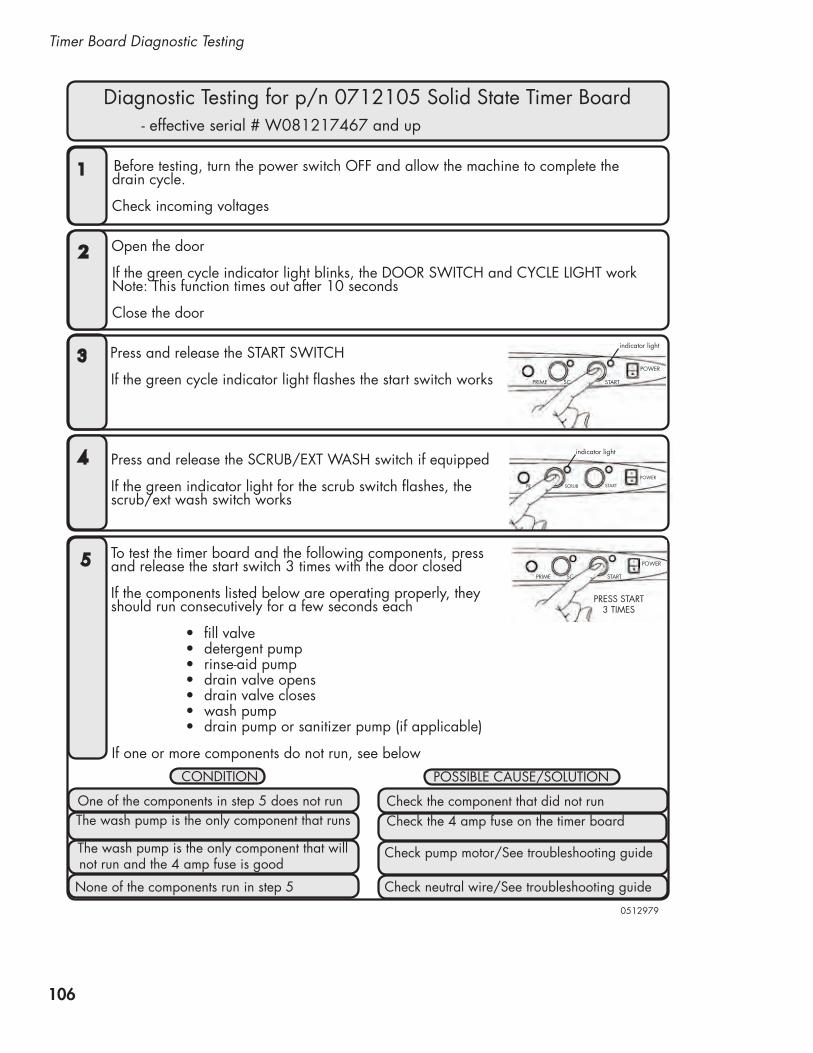
106
Timer Board Diagnostic Testing
Press and release the scrub/Ext Wash switch if equipped If the green indicator light for the scrub switch flashes, the scrub/ext wash switch works
STARTSCRUB
POWER
PR
4
before testing, turn the power switch OFF and allow the machine to complete the drain cycle.
check incoming voltages
1
Open the door If the green cycle indicator light blinks, the dOOr sWItch and cyclE lIght work Note: this function times out after 10 seconds
close the door
2
indicator light
POWER
SCPRIME START
Press and release the start sWItch If the green cycle indicator light flashes the start switch works
3
indicator light
If one or more components do not run, see below
POWER
SCPRIME START
PrEss start3 tImEs
5
fill valve •detergent pump•rinse-aid pump• drain valve opens•drain valve closes•wash pump•drain pump or sanitizer pump (if applicable)•
to test the timer board and the following components, press and release the start switch 3 times with the door closed If the components listed below are operating properly, theyshould run consecutively for a few seconds each
cONdItION POssIblE causE/sOlutION
One of the components in step 5 does not run check the component that did not runthe wash pump is the only component that runs check the 4 amp fuse on the timer board
the wash pump is the only component that will not run and the 4 amp fuse is good
check pump motor/see troubleshooting guide
None of the components run in step 5 check neutral wire/see troubleshooting guide
diagnostic testing for p/n 0712105 solid state timer board - effective serial # W081217467 and up
0512979