Embed Size (px)
Citation preview
. -· 18 6.1.2.7-1G
Installation/Maintenance Instructions Low-Voltage
Power Circuit Breakers
Type K-225 thru 2000 and K- 600S thru 2000S Stationary Mounted and Drawout Mounted
'f1.��:tf{' -•' �;c•' C >.;�', •
• •
•
•
•
-
ABB Power Distribution, Inc. Circuit Breaker Division
Jlllll ,.,1111 ASEA BROWN BOVER
www . El
ectric
alPar
tMan
uals
. com
..
..
www . El
ectric
alPar
tMan
uals
. com
m 6.1.2,7-1G .P.age'2 "''· . ..
ASEA BROWN BOVERI
CONTENTS PAGE
INTRODUCTION .................................................................................................. 3 RECEIVING AND STORAGE .............................................................................. 3 BASIC HANDLING .... .................... ........................... ............................................ 3 CIRCUIT BREAKER OPERATION ...................................................................... 3
Circuit Breaker Rating ....... ................... ...... ............ ............ ................... .. .... 3
Circuit Breaker Operation ...... .. .. ........................ ..... .......... .............. ............ 3 Closing Spring Operation (Electrically Operated) ........... ......................... 3 Closing Spring Operation (Manually Operated) ....................................... .4
Escutcheon Operating Features .. ........ ............................................................ 4 Circuit Breaker Nameplate ..................... ...................................................... 4 Manual Charging Handle (Manually Operated) ...... ............ ........ ................ 4 Manual Trip Button .......................................................................... ... ..... .... . 4 Circuit Breaker "OPEN" or "CLOSED" Indicator ...................................... .4 Automatic Trip Indicator .............................................................................. 4 Automatic Trip Alarm Contacts (Hand Reset) ......... .................................. .4
Automatic Trip Lockout (Hand Reset) ....................................................... .4 Padlocking Device ..................... ................................................................... 4 Closing Spring Charge Indicator ......................... ........................................ 6 Motor Disconnect Switch (Electrically Operated) ..................................... . 6 Electrical Close Push Button (Electrically Operated) ................................ 6 Manual Close Lever (Electrically Operated) ................... ....... .......... .. ......... 6 Racking Mechinism (Drawout Breaker) ...................................................... 6
Operation of Devices .............. ............................ .............................................. 6 Electro-Mechanical Overcurrent Trip Devices ............................ ....... ........ 6 Power Shield Solid State Overcurrent Trip Devices .... ... ........................... 6 Control Device (Eiecrlcally Operated) ......................................................... 8 Auxiliary Switches ........... ........... ..................... .. . ............ .......................... .... 8 Undervoltages Trip Device .... ....................................................................... 8
INSTALLATION, INITAL TESTING AND REMOVAL. ........................................ 9
Installation ..................................................................................................... 9 Checking Circuit Breaker Operation .... ........... .. .. ...... ..... ........... .................. 10 Emergency Operation .................................. ................................................ 1 0 Circuit Breaker Removal (Drawout Type) ................... ...... .......................... 10
MAINTENANCE ................................................................................................... 11 Safety Notes .......................................... ... .............. ... ... ...... .............. ............ 11 Periodic Maintenance Inspection ............................................................... 11 Arc Chute ...................................................................................................... 11 Contacts ........................................................................................................ 11 Insulation Structure ..................................................................................... 11
ADJUSTMENTS ........................................................ .... ........... ............................ 11 Slow Close Procedure ...................................... ......... .... ............... ................ 13 Contacts .................................................................... ........... : ......................... 13 Mechanism ................................. .. .......... .. ..... . ....... .. .. .. ...... .. .... ... .................. 15
Shunt Trip Device ............................................... .......................................... 15
Control Device .............................. ..... ...... .. ........... .. ... .... ...... ... .. ....... .. ............ 16 Magnetic Latch Device ...... ... ....... .. .... ..... .......... .... ..... ... ..... .. .. .... ... .. .. ............ 16 Electro-Mechanical Overcurrent Trip Device Adjustments ...................... 17 Solid State Overcurrent Trip Device Settings .... ....... ................................. 18
LUBRICATION .. .. ............................. ... .. .. .... ..................................... ............ ........ 18 DIELECTRIC TEST ............... .............................................................................. 19
ELECTRICAL CHARACTERISTICS OF CONTROL DEVICES .......................... 19 RENEWAL PARTS ............................. ......... . ........ ..... ... ... ................. .................... 19
www . El
ectric
alPar
tMan
uals
. com

J�J • ...
. , ...
www . El
ectric
alPar
tMan
uals
. com
'. ASEA BROWN BOVERI
INTRODUCTION These instructions apply to the type K-225 through K-2000 and K-600S t hrough K-2000S circui t breakers; 225, 600, 800, 1600 and 2000 ampere ac continuous current rating respectively. The type K-225 through K-2000 are equipped with electro-mechanical overcurrent trip devices , whereas the type K-600S through K-2000S incorporate the solid state overcurrent t rip devices. A K-1600S circuit breaker is shown on the front cover of this bulletin . The K-225 through K-2000 circuit breakers can be furnished with two or three poles for de or ac operation. K-600S through K-2000S circuit breakers are only furnished for three pole, ac operation. All circuit breakers can be furnished as drawout or stationary mounted and are available as manually or electrically operated and with electrical control devices available in various ac and de voltage combinations. The manually and electrically operated mechanisms are interchangeable 011 circuit breakers having the same current rating. Many optional features are also available. An electrically operated, drawout type circuit breaker is shown in Figure 1 , with a typical schematic d iagram shown in Figure 2. These instructions should be read thoroughly before handling, installing and/or operating the circuit breaker.
RECEIVING AND STORAGE Immediately upon receipt of the circuit breakers , examine , the cartons to determine if any damage or loss was sustained during transit . If injury or rough handling is evident, file a damage claim at once with the carrier and promptly notify the nearest District Office. Asea Brown Boveri is not responsible for damage of goods after delivery to the carrier. However, we wil l lend assistance i f notified of claims. Unpack circuit breakers as soon as possible after receipt. If unpacking is delayed, difficulty may be experienced in making a claim for damages not evident upon receipt. Use care in unpacking in order to avoid damaging any circu i t breaker parts. Check the contents of each carton against the packing list before discarding any packing material. If any discrepancy is discovered, promptly notify the nearest District Office. Information specifying the purchase order number, carton number and part numbers of damaged or missing parts should accompany the claim. Circuit breakers should be installed in the ir permanent
18 6.1.2.7-1G Page 3
location as soon as possible. (See Basic Handling below. ) If possible, a drawout circuit breaker should be stored and locked in the "DISCONNECTED" position in its compartment, with the door closed. Both the primary and control separable contacts are disconnected in this position. If the breaker cannot be installed in its compartment , it should be kept in its original carton and the carton should be sealed to prevent infi ltration of dirt . Where conditions of high humidity prevai l , the use of heaters is recommended, regardless of the method of storage selected.
BASIC HANDLING INSTRUCTIONS Once the circu it b reaker has been removed from its shipping carton, it should be turned to the upright position and placed Ofl a flat surface to avoid damage to breaker parts For safety, all handling in this position should utilize the lifting yoke (Page 20, Fig . 1 ).
CIRCUIT BREAKER OPERATION CIRCUIT BREAKER RATING
The continuous current rat ing is established by the frame size of the circui t breaker and is the number listed in the type designation; i . e . , K-600 means the circuit breaker can carry 600 amperes continuously. Exceeding these ratings may raise the temperature of the circuit breakers beyond their design l imit and thereby affect the life of the circuit breaker. Thus, any long-time pickup setting exceeding 100% of the frame size is to be used only for coordination, not for carrying increased continuous current.
CLOSING SPRING OPERATION (Electrically Operated) The two closing springs supply the power that closes the circuit breaker and also charge the two opening springs during the closing operation. The closing springs are charged by a motor. The spring energy is available to close the circuit breaker, thus referred to a.s "stored energy. " Closing springs are normally charged when the ci rcu it breaker is opened. If charged after closing, the circuit breaker can be opened and then reclosed without recharging the springs. In earlier model drawout circuit breakers, the closing springs are automatical ly d ischarged when the circuit breaker is pulled to the fu lly withdrawn position (shown in Figure 1 ) .
This prevents accidental discharge. In later models, the springs are automatically discharged when racking the circuit breaker from the disconnected to the withdrawn position.
www . El
ectric
alPar
tMan
uals
. com

: www .
Elec
tricalP
artM
anua
ls . c
om
,.., u.J • ..:: ./·1\ • .::1 PaQe.4
ASEA BROWN BOVERI
', ------------------------------------------------------------------------------------
Cl.,OSING SPRING OPERATION (Manually Operated) In one continuous downward pul l of the handle the two closing springs are charged, and near the end of the stroke, are discharged to fast close the circuit breaker . During closing, the two opening springs are charged.
ESCUTCHEON OPERATING FEATURES Manually and electrically operated circuit breakers are provided with an extendible escutcheon face plate. This escutcheon provides a central area for the controls which are mounted directly on the circuit breaker. The controls for the electrically operated circuit breaker (Figure 1) included in the escutcheon face plate are: ( 1 9) nameplate giving the various ratings assigned to the part i.cular type of circuit breaker, (13) manual trip button , ( 17) manual close lever, (12) electrical close push button switch (10) motor disconnect switch, ( 1 4) "OPEN" and "CLOSED" position indicator, (9) automatic tr ip indicator with optional facilities for alarm indication and for lockout, (1 1 ) means for padlocking the circuit breaker in the "CONNECTED", "TEST' or "DISCONNECTED" position and (1 6) closing spring charge indicator. Handle (22) is normally removed and is used for emergency closing spring charging or maintenance work. �
The manually operated circuit breaker includes a manual closing handle but does not include the electrical close push button switch, motor disconnect switch , manual close lever, spring charge indicator o r maintenance handle. All drawout circuit breakers have the racking shutter ( 15) that must be raised to allow inse rt ing of the racking crank (21 ) . A self-aligning dust plate (18) immediately behind the escutcheon face plate is used to exclude dust from the circuit breaker compartment. On d rawout type circuit breakers , the escutcheon face will protrude through the front door of the compartment when the c ircu it breaker is in the "TEST' and "DISCONNECTED" positions. In these positions, the dust plate still functions to exclude dust.
Circuit Breaker Nameplate (Figure 1 , Item 19) The circuit breaker nameplate contains information regarding (1) the manufacturer's name and address, (2) type of circuit breaker design, (3) serial number of circuit breaker, (4) continuous current rating of frame s ize, (5) short circu it current rating at rated voltages, (6 ) frequency, (7) short time current.
Manual Charging Handle (Manually Operated) The manual charging handle is a T-shaped lever used on manually operated circuit breakers to charge the closing
springs and close the circu it breaker in one continuot,Js downward stroke. Manual Trip Button ( Figure 1, Item 13 ) The manual trip b[Jtton, when pushed, t rips the circuit breaker to "OPEN." Circuit Breaker "OPEN" or "CLOSED" Indicator ( Figure 1, Item 14 ) This indicator shows the physical position of the circuit breaker contacts . Automatic Trip Indicator ( Figure 1 , Item 9 ) (Not including undervoltage, alarm switch or lockout) The automatic trip ind icator is provided as standard equipment on the K-line circuit breakers and is used to indicate the operation of the overcurrent trip device. This device is an indicator only and does not prevent the circuit breaker reclosing. Upon an overcurrent trip operation , the indicator protrudes from the front plate approximately 1 /2 inch. The automatic trip indicator should be reset after each trip indication by pushing back into its normal latch position. The operator should investigate the cause of tripping before resetting the automatic trip indicator and subsequent reclosing the circu it breaker after an outage which results in an operation of the indicator. Automatic Trip Alarm Contacts (Hand Reset) ( Figure 1, Item 9) An alarm switch for remote electrical indication , which is optional, shows when automatic tripping has occurred . This is accomplished by adding a precision snap switch to the automatic trip indicator assembly. The automatic trip ind icator actuates the roller on the alarm switch which in turn causes a normally open contact to close and a normally closed contact to open on overcurrent trip. The alarm contact is manually reset by pushing the trip i ndicator (9) back into its normal position. Automatic Trip Lockout (Hand Reset) ( Figure 1 , Item 9) An additional device (which is also optional) may be added to the automatic trip indicator assembly device which serves to mechanically prevent reclosing the circuit breaker after an automatic trip operation . When the trip indicator is pushed in, the circuit breaker mechanism can then be operated to close the circuit breaker contacts. Padlocking Device (Figure 1 , Item 1 1) All K-line circuit breakers are equipped with means of padlocking the circuit breaker mechanism in a tripfree position. This is accomplished by the use of a locking plate to maintain the manual trip button in a tripping direction when the locking plate is held forward by one or more padlocks. To obtain the condition for padlocking the ci rcu it breaker in the open position, the manual trip button is pushed inward. Then the padlock plate is pulled out and the padlock inserted into the vertical slot. In this position, the mechanism is maintained trip free and the contact arm cannot be moved to the closed position .
www . El
ectric
alPar
tMan
uals
. com

.·
www . El
ectric
alPar
tMan
uals
. com

--�
ASEA BROWN BOVERI
18
16 15 19 14 21 13 12 17 11 10 9 B
1.
2.
3.
4.
5. 6.
7.
B.
9.
10.
-� ¥ft.-• (.: • r ·�-- ,.
, I -f-
Arc Chute 11. Lock 1 ng Hasp 21. Racktng C:ank
Auxr11 ary s-..1 t ch 1 2. Electrical Close Push Butt on 22. Removable �a1ntenance
Secondary Seoarable Contacts 13. Manu a I T r 1 p But ton 23. Track
Rack r ng Cam Assemb I y 14 "OPEN .. or ''CLOSED'' \nd1cator 24. Latch
Overcurrent Tr10 Oev1ce 15. Racking Shutter 25. Reta1n1n5 :crew
Posttion1ng ?tns i 6. Clostng Sprtng Charge lndrcator 26 Reta1ne·
Clostng Spr rng �hargt"g llotor 17. �anual Close Lever "' Pos 1 t r � .. "0 I Cal 0 I "
Escutcheon Asser::oly i B. Se i ! Altgnrng Oust PI a 12 28 Cradle
Automat r c T rr o lnd1cator ;g. Nameplate
Motor Or scornect Swr ::.1 20. L1fttngYoke
Fig. 1 -Typical Electrically Operated, Drawout Type K- 1 600 Circuit Breaker
25
26
2
28
4
24 5 27
6 23
H�ndle
IB 6.1.2.7-1 G Page 5
www . El
ectric
alPar
tMan
uals
. com

www . El
ectric
alPar
tMan
uals
. com
· 18 S.1:2.7-1G . -. Page.'6 ·
On circuit breakers equipped with drawout mechanism, the padlocking device is associated with the drawout interlocking mechanism so that the circuit breaker cannot be moved from any of its three basic drawout positions of "CONNECTED", ''TEST" or "DISCONNECTED" with the padlocking in effect. Closing Spring Charge Indicator (Electrically Operated) ( Figure-1, Item 16) Under normal operating conditions, the closing springs are automatically charged after each tripping operation. However, there are occasions when the springs will be in a discharged state. Therefore, it is desirable that means be available to indicate the charged or uncharged condition of the closing springs. This is accomplished by a visual indicator seen through an aperture in the escutcheon plate. The indicator is marked "SPRINGS CHARGED" and "SPRINGS DISCHARGED." Motor Disconnect Switch (Electrically Operated) (Figure 1, Item 10) The motor disconnect switch is a double pole, single- throw toggle type switch connected in series with the charging motor circuit and is used to disconnect the motor from the voltage source. This cut-off switch is used (1), when it is desirable to prevent automatic recharging of th� closing springs just prior to taking the circuit breaker out of service for maintenance and (2), for control wiring dielectric test. The motor must be disconnected for the control wiring dielectric test and subsequently tested at 540 V ac or 760 V de. Electrical Close Push Button (Electrically Operated) (Figure 1, Item 12) The electrical close push button is used to electrically close the circuit from the escutcheon. This contact is connected in series with the latch release coil (52X) . Energizing the latch release coil allows the charged springs to close the circuit breaker. Manual Close Lever (Electrically Operated) (Figure 1 Item 17) The manual close lever is provided on electrically operated circuit breakers to provide a means of closing the breaker without control power. Racking Mechanism (Drawout Breaker) The racking mechanism may be used to move the circuit breaker to any one of its three positions ("CONNECTED", "TEST" or "DISCONNECTED" ) . All of these positions are attainable with the cubicle door closed. The racking shutter ( 15, Fig.1), which must be lifted to gain access to the racking mechanism, is interlocked with the circuit breaker so that the circuit breaker contacts must be open before the shutter may be lifted to rack the circuit breaker to another position. The circuit breaker cannot be closed when the shutter is open. The circuit breaker may be padlocked open
ASEA BROWN BOVERI
by means of the locking hasp. This automatically locks the racking mechanism. With the "TRIP" button (13, Fig.1) depressed, the locking hasp (11, Fig1) may be pulled 0utward, accommodating from one to three padlocks, when the shutter is closed and the circuit breaker is tripped. The shutter cannot be lifted and the breaker contacts can not be closed when the locking nasp is restrained by one or more padlocks. There are two sets of arrows and indicating lines to show the circuit breaker position. One set is utilized with the compartment door closed and one set with the door open.
OPERATION OF DEVICES Electro-Mechanical Overcurrent Trip Devices Type K-225 thru K-2000 Circuit Breakers (Figures 14 thru 18 ) (A) Type OD-3 General Purpose Overcurrent Trip Device. The type OD-3 overcurrent trip device, for general purpose applications, provides long-time delay tripping on moderate overcurrents which are above the long-time pickup setting; and instantaneous tripping on fault currents above the instantaneous trip setting. This device must be properly set to provide adequate protection for an electrical system. Three adjustment screws on the bottom of the device provide independent control of the long-time pickup, instantaneous pickup and amount of time delay. The nameplate of this device shows the setting of these adjustments and the range of settings which are available. For information on the time-current characteristics of this device. request a copy of TD-6693. (B) Type OD-4Selective OvercurrentTrip Device. The type OD-4 overcurrent trip device, for selective tripping applications, provides long-time delay and short-time delay tripping. Independent adjustment of both pickup and time delay is provided for both types of tripping. The name late of this device shows the settings which are available. For information on the time-current characteristics of this de-vice, request a copy of TD-6694.
·
(C) Type OD-5 Triple-Selective Overcurrent Trip Device. This overcurrent trip device is similar to the OD-4 except that an instantaneous trip characteristic is added to the long-time delay and the short-time delay functions provided on the OD-4. For information on the time-current characteristics of this device, request a copy of TD-6695. (D) See Table 1·on facing page for complete list of ElectroMechanical standard overcurrent trip devices available. See Maintenance Section for adjustments. Power ShieldTM Solid State Overcurrent Trip Devices Type K-600S thru K-2000S Circuit Breakers ( See Figure 19) This device includes the power supply sensors. overcurrent sensors. Power Shield solid state logic assembly. magnetic latch and the interconnecting wiring. Each phase
www . El
ectric
alPar
tMan
uals
. com

..
.•
www . El
ectric
alPar
tMan
uals
. com
·.
.. ,,11'11' ' -'SEA BROWN BOVERI
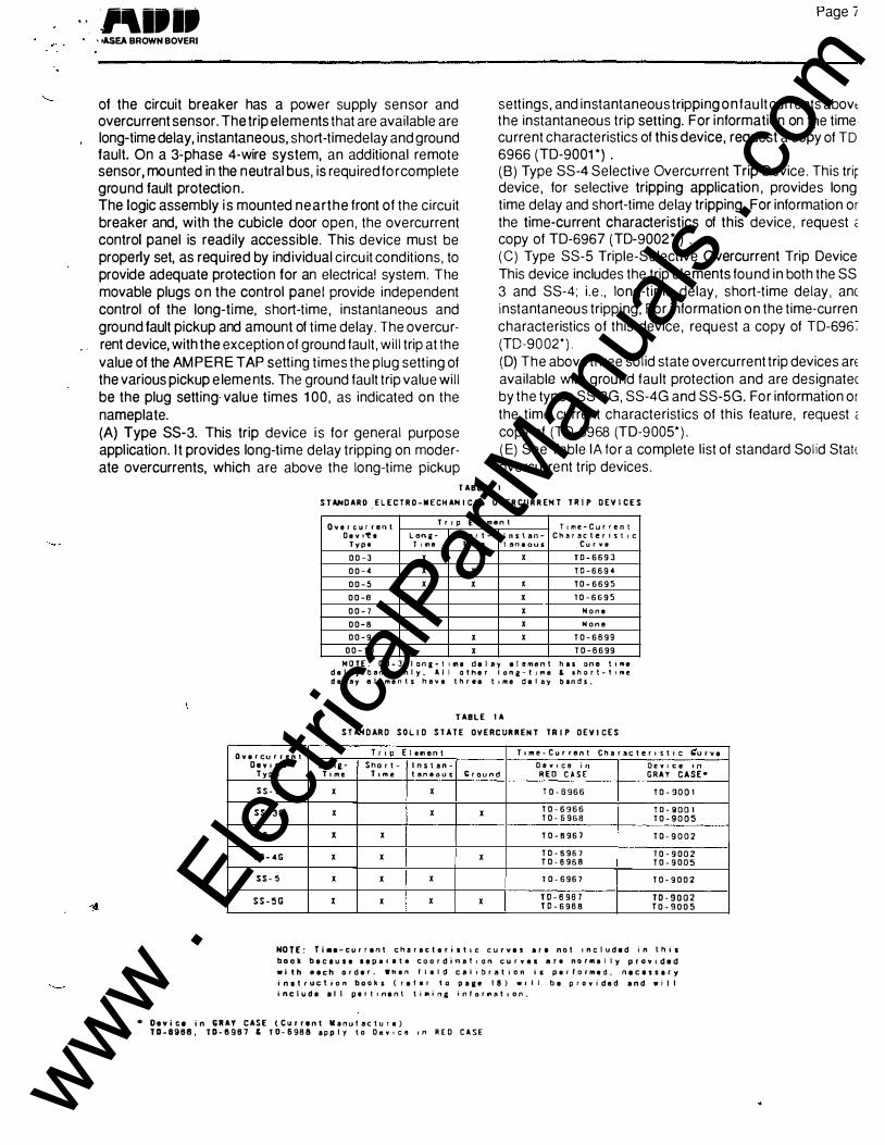
of the circuit breaker has a power supply sensor and overcurrent sensor. The trip elements that are available are long-time delay, instantaneous, short-timedelay and ground fault. On a 3�phase 4-wire system, an additional remote sensor, mounted in the neutral bus, is required forcomplete ground fault protection . The logic assembly is mounted near the front o f the circuit breaker and, with the cubicle door open, the overcurrent control panel is readily accessible. This device must be properly set, as requi red by individual circuit conditions, to provide adequate protection for an electrical system. Tt1e movable plugs o n the control panel provide independent control of the long-time, short-time, instantaneous and ground fault pickup and amount of time delay. The overcurrent device, with the exception of ground fault, will trip at the value of the AMPERE TAP setting times the plug setting of the various pickup e lements. The ground fault trip value will be the plug setting value times 1 00, as indicated on the nameplate. (A) Type SS-3. This trip device is for general purpose application. It provides long-time delay tripping on moderate overcurrents, which are above the long-time pickup
Page I
settings, and instantaneous tripping on fault currents abovt the instantaneous trip setting. For information on the time current characteristics of this device, request a copy of TO 6966 (TD-9001 *) . (B) Type SS-4 Selective Overcurrent Trip Device. This trir device, for selective tripping application , provides long time delay and short-time delay tripping. For information or the time-current characteristics of this device, request ;: copy of TD-6967 (TD-9002* ) .
(C) Type SS-5 Triple-Selective Overcurrent Trip Device This device includes the trip elements found in both the SS 3 and SS-4; i.e., long-time delay, short-time delay, anc instantaneous tripping, For information on the time-curren characteristics of this device, request a copy of TD-696� (TD-9002*). {D) The above three solid state overcurrent trip devices arE available with ground fault protection and are designatec by the types SS-3G, SS-4G and SS-5G. For information or the time current characteristics of this feature, request < copy of (TD-6968 (TD-9005*). (E) See Table lA for a complete list of standard Solid Stat( overcurrent trip devices.
TABLE I
STANDARD _ELECTRO-MECHANICAL OVERCURREHT TRIP DEVICES
o�ercurrenl T r I p Element
T11ne-Current Oev t'!e Lone- Short- Ins tan- Character 1st tc
Type T I lnlt Ttme tan•ous Cur v •
00-J X X TD-669J
00-4 X X TD-6694
00-5 X X X T0-6695
00-6 X X T0-6695
00-7 X Hone
00-8 X Hone
00-9 X X T0-6899
00-10 X T0-8699
HOlE: 00-3 lona-ttltl delay element has one til'llle delay band only. All other lone-t•me ' short-ttrwe delay elements hav e three ttme delay bands.
TABLE lA
STANDARD SOLID STATE OVERCURRENT TRIP DEVICES
Overcu r r en t Trip [I e11en t Ttme-Current Charactertstic t:'u r ve Oevtce Lana- Sho rt- Ins tan- Oev•ce '" Oevaca '"
Typo Time T tme taneous Ground REO CASE GRAY CASE•
S S- 3 X X 10-6966 10-9001
SS-3G X X X T0-6966 T0-9001 T0-6968 T0-9005
SS-4 X X T 0-8 96 7 T D - 9002
SS- 4G X X X T0-8967 10-9002 T0·6968 T0-9005
SS- 5 X X X 10·6967 T0-9002
SS-5G X X X X T0-6967 TD-9002 TD-6988 T0-9005
NOT£: Tl•e-current characteristac curves are not Included in this
book beCIUII aepar1te coordinataon curves ar• nor�al ly provided
with eech order. Wh•n fi•ld ca l t brat ion is P•rlormed, necessary
inttruction books (ref•r ta pa1e 18) wall be provided and will include all pert1nent tiMina inforn8t1on.
• Device in GRAY CASE (Current Manulactura) TD-8988, TD-6987 & TD-6988 apply to Oovoco •n REO CASE
www . El
ectric
alPar
tMan
uals
. com

. -.
www . El
ectric
alPar
tMan
uals
. com
IB 6:1.2,7-1G Page 8-·
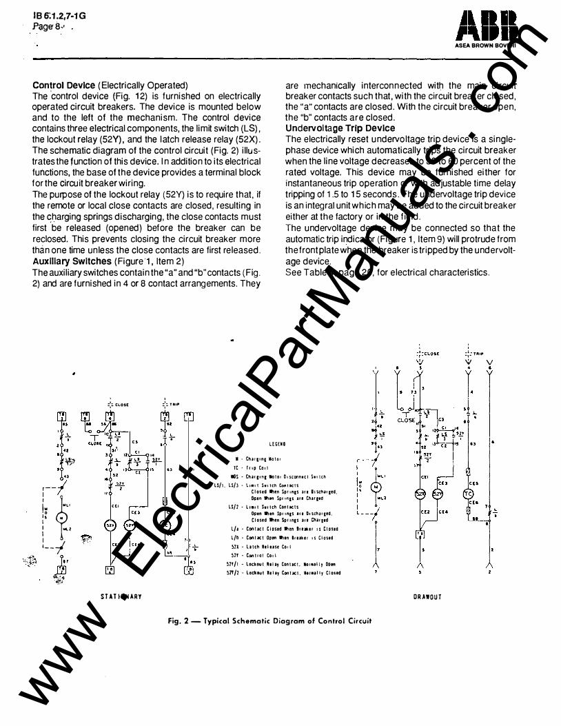
Control Device ( Electrically Operated) The 'control device (Fig. 12) is furnished on electrically operated circuit breakers. The device is mounted below and to the left of the mechanism. The control device contains three electrical components, the limit switch {LS), the lockout relay (52Y ) , and the latch release relay (52X). The schematic diagram of the control circuit (Fig. 2) illustrates the function of this device. I n addition to its electrical functions, the base of the device provides a terminal block for the circu it breaker wiring. The purpose of the lockout relay (52Y) is to require that, if the remote or local close contacts are closed, resulting in the �harging springs discharging, the close contacts must first be released (opened) before the breaker can be reclosed. This prevents closing the circuit breaker more than one time unless the close contacts are first released. Auxiliary Switches ( Figure 1 , Item 2) The auxiliary switches contain the "a" and "b" contacts (Fig . 2) and are furnished in 4 or 8 contact arrangements. They
I
::: CLQS( :;:. HI!�
.. �� l .. ..
. , 14
uma
�")' ... .--
., II • · Ch�rt•ni Motor
TC · T11p Coli
ASEA BROWN BOVERI
are mechanically interconnected with the main circuir breaker contacts such that , with the circuit breaker closed, the "a" contacts are closed. With the circuit breaker open, the "b" contacts are closed. Undervoltage Trip Device The electrically reset undervoltage trip device is a singlephase device which automatically trips the circuit breaker when the line voltage decreases to 30 to 60 percent of the rated voltage. This device may be furnished either for instantaneous trip operation or with adjustable time delay tripping of 1 .5 to 1 5 seconds . The undervoltage trip device is an integral unit which may be added to the circuit breaker either at the factory or in the field. The undervoltage device may be connected so that the automatic trip indicator (Figure 1 , Item 9) will protrude from the front plate when the breaker is tripped by the undervoltage device. See Table 4, page 20, for electrical characteristics .
' :�: r.-t� "" v • •
I
••
4l
;--1 lOS· Cha'l'"llolo• D•sconn•cl S••tch
lS/1. LS/J - \.11111 t SwtiCf'l Coni acts
·<'?"l ·:..· -.
i: �
Is M I I ..._, I I '--1
ft)' I f.' .$ ·q:;;
�
STAT HlNARY
Cloud �en Spnn1s 111 81Sd'1i!il!d, Open lhM Spr '"I' JJI Cturcec
LS/1 • l1111 S.oleh Conlacls Open •un Spt•nas au Dtschuied. Closed 'M'ten Sprtncs au Cha111d
L/a • Conloc& Cloud lll•n Brul.u os Cloud
L/b ·CanUel Open Ilion lrul.11 11 Closed
511- latch lllusr Co• I �2! • Conlool Coli
�11/1 • loc:l.oul hlay Conllc:t. •oroally Open
�71/1 • loc:hul Relay Conlxt. •••ully Closed
Fig. 2- Typical Schematic Diagram of Control Circuit
ORA lOUT
www . El
ectric
alPar
tMan
uals
. com

. .
. \ . . '
.-
www . El
ectric
alPar
tMan
uals
. com
INSTALLATION, IN IT IA L TESTING AND REMOVAL · {Drawout Stationary)
FOR SAFETY: When installing or rerr breakers, the supply for primary and ��ci: be de-energized at all times. Testing 0f ·
breakers to be done with the primary ., •: energized. For initial installation of drawout brec.lt: -
NECTED"position, the supply for the C'. be de-energized. Testing of the drawou' •
in the test position. NOTE: (K 225 thru K-2000 Circ:J inserting the circuit breaker into the�,·· the breaker in the upright position. exer' time armatures (5/8" wide armatures) ' ' resistance to motion has increased. ind: -
dashpot is functioning properly lmr",..T'' result because the circuit breaker is shit--r·• r:
back. This causes the oil in the dashpor :·_ an air bubble can be trapped under tli•' "I: · .
removes the air to permit proper opw: . . ·
INSTALLATION (Stationary Type) Lifting yoke (20, Fig. 1) should be used to move the breaker to the switchboard; however, other handling means will be required to move the breaker into position inside the switchboard.
INSTALLATION (Drawout Type) To insert the circuit breaker into its comportment, proceed as described below: (Refer to Fig. 1) 1. The circuit breaker must be in the "OPEN" position, the racking crank t�Hned in the counterclockwise direction fully against its stop, and the motor disconnect switch ( 1 0) (electrically operated circ."'it breakers only) in the "OFF" position. 2. Open the compartment door and pull out the right-hand and left-hand tracks 123) to the full{'extended and latched position. 3. Using a lifting yoke, lower the circuit breaker so that the positioning pins (6) ( two each side of circuit breaker) rest in the cut-out sections of each track (23). 4. Remove the lifting yoke and push the circuit breaker toward the compartment. The circuit breaker will slide in the cut-out sections of the tracks until the positioning pins reach the end of the cutouts. An additional positive push will automatically release the two latches (24). This allows the circuit breaker to move toward the compartment until the racking cams (4) stop against their guides on the cradle (28).
IB 6.1.2.7-1G Page 9
5. Lift shutter (15) covering the racking opening,. insert racking crank, and turn crank clockwise, pass through the "DISCONNECTED" position, until the position indicator on the cradle (left side) shows "TEST" position. Remove racking crank.
CHECKING CIRCUIT BREAKER OPERATION IN "TEST" POSITION (Electrically Operated, Drawout Type) (Refer to Fig.1) 1. Manually reset automatic trip indicator (9) if it protrudes approximately 1/2 ". Push in to reset. 2. Turn motor disconnect switch (1 0) to "ON" position and closing springs will automatically charge. 3. Close circuit breaker by local close button and trip by local trip button. NOTE: All breakers have a manual trip button. The local close button for electrical breakers is standard. The local trip button for electrical breakers is optionaL 4. Close and trip circuit breaker by means of remote control switch. 5. Check each auxiliary device for proper operation. 6. Close the circuit breaker and check that the shutter ( 15 ) cannot be lifted to allow insertion of the racking crank. This demonstrates that the circuit breaker could not be racked out while closed in the connected position.
CHECKING CIRCUIT BREAKER OPERATION IN "TEST" POSITION (Manually Operated, Drawout Type) (Refer to Fig. 1 and Cover Photo) 1 . Manually reset automatic trip indicator (9) if it protrudes approximately 1/2". Push in to reset. 2 . Close the circuit breaker by pulling down on the 'T handle. 3. Trip by manual "TRIP" button (13). 4. Check each auxiliary device for proper operation. 5. Close the circuit breaker and check that the shutter ( 15) cannot be lifted to allow insertioB of the racking crank. This demonstrates that the circuit breaker could not be racked out while closed in the connected position .
CHECKING CIRCUIT BREAKER O PERATION IN "CONNECTED" POSITION (Drawout Type) (Refer to Fig. 1 ) With the circuit breaker in the "OPEN" position and the motor disconnect switch ( 1 0) in the "OFF" position, rnsert the racking crank and turn clockwise until the positron indicator on the cradle shows "CONNECTED" position.
www . El
ectric
alPar
tMan
uals
. com

\• ,.
. .
www . El
ectric
alPar
tMan
uals
. com
IB 6.1.2.7-1G Page to . .
CHECKING CIRCUIT BREAKER OPERATION (Stationary Type ) Follow the same procedure as for the drawout circuit breaker, except the circuit breaker will be in the "CONNECTED" position . Primary supply circuit must be deenergized.
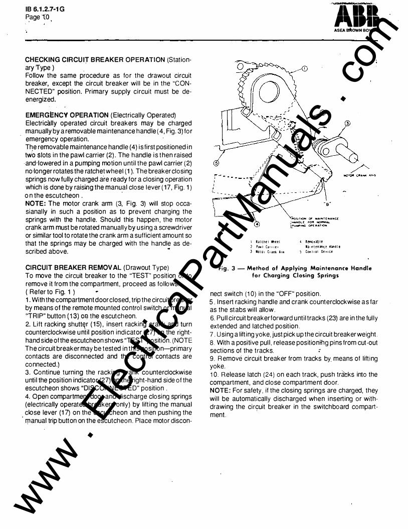
EMERGENCY OPERATION (Electrically Operated) Electrically operated circuit breakers may be charged manually by a removable maintenance handle (4, Fig. 3) for emergency operation. The removable maintenance handle ( 4) is first positioned in two srots in the pawl carrier (2) . The handle is then raised -and·lowered in a pumping motion until the pawl carrier (2) no·longer rotates the ratchet wheel (1 ). The breaker closing springs now fully charged are ready for a closing operation which is done by raising the manual close lever (17, Fig. 1 ) o n the escutcheon .
·
NOTE: The motor crank arm (3, Fig. 3) will stop occasianally in such a position as to prevent charging the springs with the handle. Should this happen , the motor crank arm must be rotated manually by using a screwdriver or similar tool to rotate the crank arm a sufficient amount so that the springs may be charged with the handle as de-scribed above. ..
CIRCUIT BREAKER REMOVAL (Drawout Type) To move the circuit breaker to the "TEST" position or to remove it from the compartment, proceed as follows: ( Refer to Fig. 1 ) 1. With the compartment door closed, trip the circuit breaker by means of the remote mounted control switch or manual ''TRIP" button (13) Olil the escutcheon. 2. Lift racking shutt�r ( 1 5) , insert racking crank and
_turn
counterclockwise u ntil position indicator (27) on the nghthand side of the escutcheon shows "TEST" position. (NOTE The circuit breaker may be tested in this position-primary contacts are disconnected and the control contacts are connected.) 3. Continue turning the racking crank counterclockwise until the position indicator (27) on the right-hand side of the escutcheon shows "DISCONNECTED" position . 4. Open compartment door and discharge closing springs (electrically operated breakers only) by lifting the manual close lever (1 7) on the escutcheon and then pushing the
· l")lanual trip button on the escutcheon. Place motor discon-
JliiJI ,.,1,' ASEA BiliOWN BOVERI
PQSITI()H 0# lllAINT(NANt£ �OL( f'O" ,.,....... ..... PV�Itrrol(; Of"(IIIIAT'oON
1 A:atcnet Whul 2 Pa•l c� I I I e I
3 Mator Cr�nk Arm S Cant rot De YICt
Fig. 3- Method of Applying Maintenance Handle for Charging Closing Springs
nect switch (1 0) in the "OFF" position . 5 . Insert racking handle and crank counterclockwise as far as the stabs will allow. 6. Pull circuit breaker forward until tracks (23) are in the fully extended and latched position. 7. Using a lifting yoke, just pick up the circuit breaker weight. 8. With a positive pull, release positioniilg pins from cut-out sections of the tracks. : 9. Remove circuit breaker from tracks by means of lifting yoke. . 1 0. Release latch (24) on each track, push tra'tks into the compartment, and close compartment door. NOTE: For safety, if the closing springs are charged, they will be automatically discharged when inserting or withdrawing the circuit breaker in the switchboard compartment.
www . El
ectric
alPar
tMan
uals
. com
·-!>
·\.__...-·
ASEA BROWN BOVERI
MAINTENANCE ' SAFETY NOTES
De-energize both primary and contra: .�
ing any inspections , adjustments or rs:::.;:•· Make certain breaker is open by obsP'" -
Fig. 1 ) , and closing springs are not cfc.::,··
indicator ( 1 6, Fig. 1 ) . When it is necessary that the closing s; ·
Or the CirCUit breaker be ClOSed, ill?.k·?. Si, operating parts. Stationary breakers should be r:"•e''' the control circuit energized and ti'•' energized. Drawout breakers should t>' · ·
.. posit ion for checking the breaker o:>> ·.
inspection, adjustments, cleaning or rerl:• the drawout circuit breaker should be with,-.· to a suitable area. Stationary breakers should likewise hr:
removal is not possible. then the or;r;,;; r:
sources MUST BE DE-ENERGiZED It is HAZ ARDOUS to work on arw :ire; 1 '' " located on extended cradle r2i.s
PERIODIC MAINTENANCE INSPECTION
. '
The safety and successful functioning of fne connected apparatus depends upon the proper operation of the circuit breaker. Therefore , it is recommended that a maintenance program be established that will provide for a periodic inspection of the circuit breaker as follows:
K-225 - After 2,500 operations K-600, K-600S- After 1 ,750 operations K-800 , K-SOOS- After 1,750 operations K-1 600, K-1 600S - After 500 operations K-2000, K,-2000S After 500 operat ions
The above inspection periods apply for no load or load current switching. If the listed number o f operations are not completed in the first year of service, the circuit breakers should be inspected regardless. The circuit breaker should also be inspected after a short circuit o r severe overload interruption , regardless of time period or number of operations. Where unusual service conditions. as covered by ANSI Standard C37. 1 3, exist, it must be assumed that these conditions were considered at the time of order; that the equipment supplied was designed for the special application; and that an appropriate supplemental maintenance program has been developed. These maintenance instructions only cover circuit breakers used under the standard usual service conditions. The inspection should include opening and closing the circuit breaker electrically and manually. The unit should be
'\"';:t� .. �.�� ....... -. I •-•• •-
1' .' •. ,··. .. . F;'age 11 �· . . . .
visually inspected for loose or damaged parts. Arc chutes. contacts and insulation structure shoyld bEfJ.specfed as described below. : ARC CHUTE (Refer to Fig. 1 ) Removal 1 . If the circuit breaker has a solid s�.9te·overcurrent trip device , it is necessary to remove two 1l4" diameter screws fastening the solid state control assembly. Move the assembly for access to the arc chute ret'aining screws. 2. Loosen the retaining screw (25) and remove the screw and retainer (26) .
·
3. Pull the arc chute forward slightly then lift to remove . Examination 1 . Discoloration or slight eroding is not harmful. 2. Arc runners or cooling plates that are burned , or moldings that are severly cracked or broken require replace-ment of the arc chute.
- · -
Replacement 1 . Properly position the arc chute in the upper molding. 2. Position retainer (26) and insert and tighten screw (25). 3. Replace the solid state control assembly.
CONTACTS 1. Remove dirt or grease on contacts with a clean lintless cloth. 2. Pitting or discoloration is not detrimental unless it interferes with proper contact adjustment. 3. Small burrs on the arcing contacts to be removed by filing along contour of the contact. Do not let filings fall into the mechanism. 4. Replace badly burned and pitted contacts that do not meet correct adjustment requirements . 5. If contacts are replaced or filed, then it is necessary tc check the contact adjustment. NOTE: Several operations at two week intervals will re move the effects of oxidation.
INSULATION STRUCTURE : Insulated parts should be checked for damage. Dust anc dirt should be removed by air or wiped with a clean lintles: cloth. Do not use any oil base solvents. Spray solvents var; as to type and are questionable. However. externally at rea terminals is the only critical area, which is easily wiped o
blown out with air, so other methods are not necessary !
contamination is so great. means are probably necessar to isolate.the entire equipment.
ADJUSTMENTS FOR SAFETY: See SAFETY NOTES in MAINTENANCI section. NOTE: The operating mechanism must be operated slow!) as described in section SLOW CLOSE PROCEDURE
www . El
ectric
alPar
tMan
uals
. com
... •' \
18 6:t.2.7·1 G Page 12.
. ;
2
3
Escutcheon Dust PI ate
4
Sp11n2. Dust PI ate
5
Sp11n2 l1nk Guard
4 Box, £scutcheon <R•ght·Hand S1de) Hold-Up latch
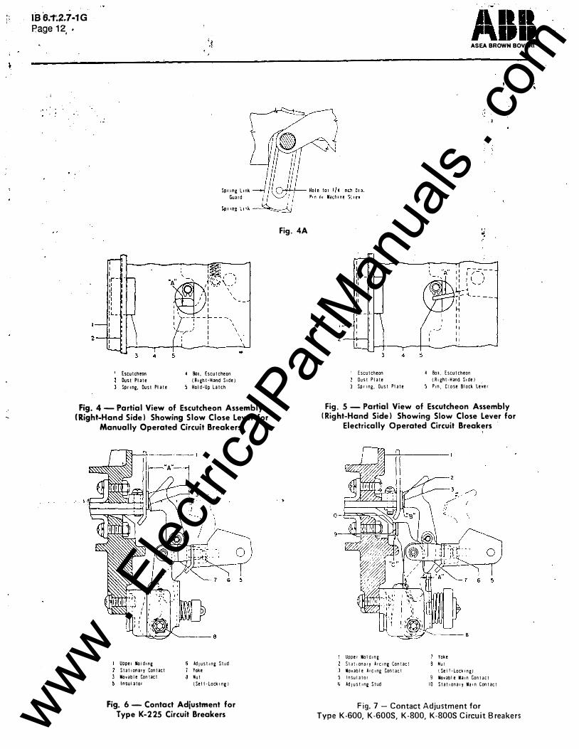
Fig. 4 - Partial View of Escutcheon Assembly (Right-Hand Side) Showing Slow Close Lever for
Manually Operated Circuit Breakers
Uppeo lloldon2 Stat1onuy Contact liovable Con tact In sui a tor
AdJuSt 102, Stud Toke Nut (Sell·lockon2)
Fig. 6- Contact Adjustment for Type K-225 Circuit Breakers
Fig. 4A
. >
Escutcheon Oust P late
4
Spr 1ng, Oust Pt ate
5
ASEA BROWN BOVERI
4 Box, Escutcheon (R•ght-Hand Sode)
,. "\
Prn, Close Block le�er
,J
Fig. 5 - Partial View of Escutcheon Assembly (Right-Hand Side) Showing Slow Close Lever for
Electrically Operated Circuit Breakers
Upper Mol drn�
S I a It onaq Arc r n2 Cant act
lllovabl e Arc rng Contact Insulator AdJust '"2 Stud
Yoke
Nut 1 Sel Hock on g)
9 liovabl e Marn Con tact 10 Statronaq lllarn Contact
Fig. 7 - Contact Adjustment for
Type K-600, K-600S, K-800, K-800S Circuit Breakers www . El
ectric
alPar
tMan
uals
. com
\... .........
when performing any adjustment requ i riv ' ment.
In order to close the circuit breaker, the rCJc
in drawout circuit breakers must be t u rr· such that the racking shutte r ( 1 5 , F ig. 1 1 i c: racking crank (21 , Fig. 1 ) is removed.
SLOW CLOSE PROCEDURE NbTE: The circuit breaker should be ci�F'' the slow close procedure to keep it f ro m : 1 Manually Operated Circuit Breakers R ,, f r
otherwise noted. 1 . On K-1 600, K-1 6008, K-2000 and K-20008 circuit break-
• · ers, at each of the two spring guards, loosely install V4 inch diameter pins or machine screws. (See Fig . 4A) 2. Insert a screwdriver or rod through the hole in the escutcheon box (4) · and mechanism housing assembly (right-hand side when facing the front of the circuit breaker) . 3. Using the top of the hole as the fulcrum and the screwdriver or rod as the lever, depress the hold-up latch (5) at "A" and, at the same time. pull the operating handle downward to s lowly close the circuit breaker contacts . 4. On K-1 600 , K-1 6008, K-2000 and K-2000S circuit breakers, remove the two V4 inch diameter pin� or machine screws installed in step 1 , after the slow close operation is complete. Electrically Operated Circuit Breakers NOTE: The charging cranks must be reset (see steps 8, 9 , and 10 below) after the last slow close operation, or future electrical operation will be impossible. Refer to Fig. 5 unless otherwise noted . 1 . The closing springs must be charged; see spring charge indicator ( 1 6 , Fig. 1 ) . 2. Insert a sc(ewdriver or rod through the ho!e in the escutcheon box (4) (right-hand side when facing the front of the circuit breaker) and depress the close block lever pin (5) at "A". 3. With the close block lever pin (5) held in the down position , l ift the manual close lever ( 1 7, Fig. 1 ) . The close block lever pin (5) will remain in the down position. 4. Insert the maintenance handle in the ratchet carrier and operate the handle to slowly close the contacts . (See Fig. 3 and "Emergercy Operation".) � To repeat the slow close operat ion , continue with the following steps : 5. Insert the maintenance handle and continue the chargingoperation until the indicator ( 1 6, Fig. 1 ) shows "SPRINGS CHARGED" 6. Push manual "TRI P" button ( 1 3 , Fig. 1 ) to open the contacts.
1 8 6 .1 .2.7- 1 G • �age 1 3
.
7. Repeat steps 2, 3 , and 4 above for the slow . close operation. ·
To reset the charging cranks for normal electrical operation, proceed as follows 8. Repeat steps 5 and 6 above. 9. Lift manual close lever ( 1 7 , F ig . 1 ) to close the contacts. 1 0. Push the manual "TR I P" button ( 1 3, Fig. 1 ) to open the contacts The circuit breaker is now ready for normal service operation with the charging cranks reset and the closing springs discharged. CONTACTS Type K-225 Circuit Breakers ( R efer to Fig. 6) 1 . The hex . portion of the adjusting stud (6) must be centered, within 1 /1 6 inch , betwee n the yoke (7) and the insulator (5) . NOTE: On some circuit breakers , the hex. portion of the adjusting stud (6) must be centered between the locknut on the adjusting stud and the insu lator. NOTE : In the fol lowing steps 2 and 3, if adjustment is required, always turn the adjusting stud (6) in the direction to increase the contact pressure (counter- clockwise when viewed from the insulator) . 2. Contact pressure is set by adjust ing stud (6) for 1 3/4 inches, plus or minus 1 /32 inch open air gap measured at "A". Any adjustment of contact pressure must be followed by step 3 . 3 . Following the slow close p rocedure, slowly close the circuit breaker until the fi rst contacts (2 and 3) just touch. The other two poles should be within .032 inch of touching. If not within .032 inch, then adjust stud (6) of these two poles in the d irection to increase pressure until all three poles touch within .032 inch , If for any reason the breaker is d isassembled and the contact structure Figures 6 and 7 is replaced or disassembled, the torque of the nut ((8) Figu res 6 and 7)) should be checked. This should be adju�ted to be between 1 5 and 25 foot pounds. This wil l provide sufficient side pressure on the hinge joint so the joint will be capable of adequately carrying its current rat ing. Type K-600, K-6005, K-800, K-8005 Circu i t B reakers (Refer to Fig . 7) 1 . The hex. portion of the adjusting stud (6) must be centered, within 1 /1 6 inch, between the yoke (7) and the insu lator (5) . NOTE : On some circuit breakers , the hex . portion of the adjusting stud (6) must be centered between the locknut on the adjusting stud and the insu lator 2 . Contact pressure is set by ad justing stud (6) so that there is a 5/64 to 3/32 inch gap, at "A" , with the circuit breaker
www . El
ectric
alPar
tMan
uals
. com

�•s s;f.2.7-1 G Page J4.
. � · < • ;
ldj u s t r n& Stud lo•ina llain Coo tacts lrcrna Coo ucts ..
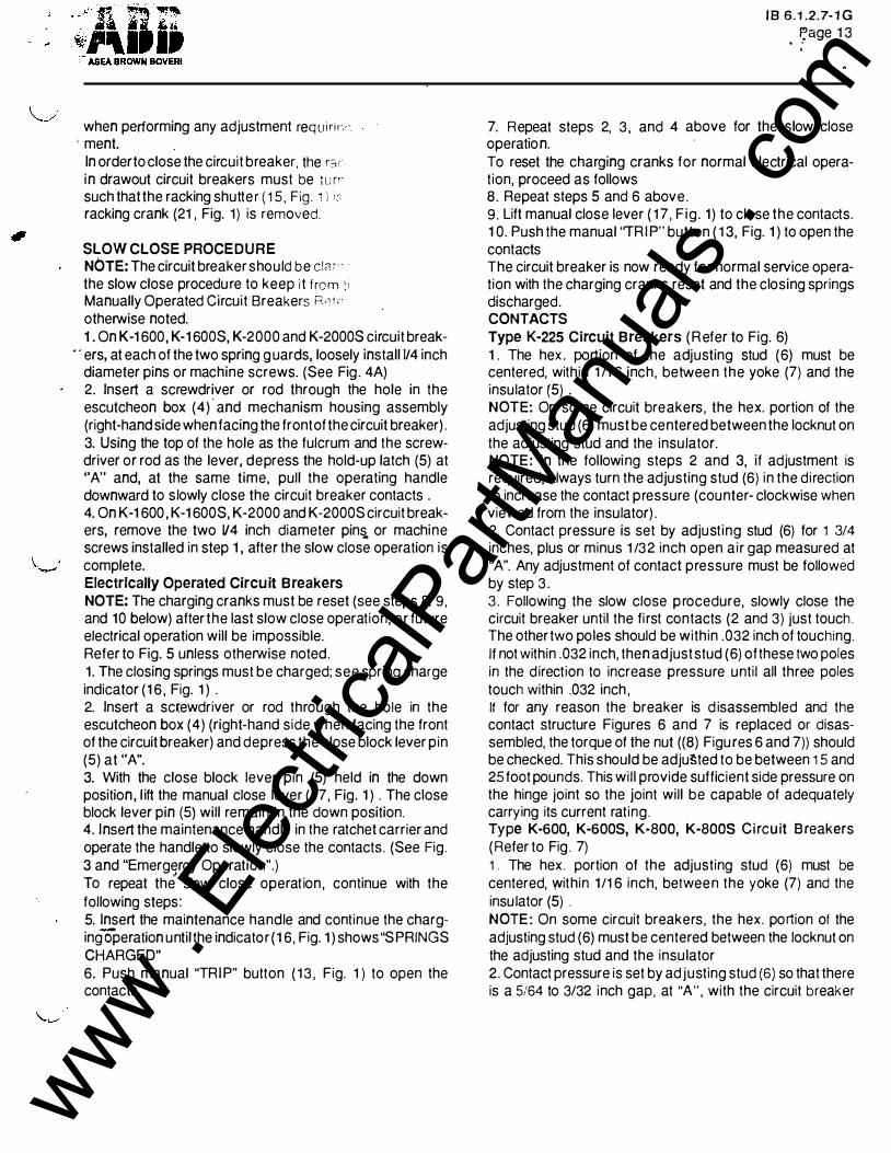
Fig.· 8 - Contact Adjustment for Type K-1 600, K-2000, K-1 6005 and K-20005 Circuit Breakers
. � ...
Trip lod IIKhanr sa Housin& (lolt·MIIId Sido) lountina Scru
Llltlr lar T r r p Ellonsion .... , ... tor i
Fig. 1 0 - Shunt Trip Device Adjustment Type K-225 thru K-2000,
K-1 6005 and K-20005 Circuit Breakers
4
sr«IOlO sCALe (P>-..... .,... l"''"t )
ASEA BROWN BOVERI
Fig. 9 - Latch Engagement and Tripper Bar Latch Engagement Adjustment
LA TCI-l tJrvtT
F ig. 11 - Shunt T rip Device Adjustment Type K-600S, K-800S C i rcuit B reakers
www . El
ectric
alPar
tMan
uals
. com
closed. This can be checked with 5/64 and 3/32 dia. wires (go and no-go) bent at 90 degrees. The 5/64 to 3/32 dimension is equivalent to .025 to .032 wipe, vertical movement of the main contacts during main contact engagement of the slow close operation. After adjusting, reclose the circuit breaker and recheck, Readjust if neces-
. sary. Any adjustment of contact pressu re must be followed by step 3. Note that, after operation 3 is completed, contact ·pressure may exceed the 3/32 inch dimension on two poles. This is acceptable. 3. Following the slow close procedure, slowly close the circuit breaker until the first contacts (2 and 3) just touch. The other two poles should be within .032 inch of touching.
· · If not within .032 inch , then adjust stud (6) of these two poles in the direction to increase pressure unti l all three poles touch within .032 inch. It tor any reason the breaker is disassembled and the contact structure Figures 6 and 7 is replaced or disas-
; sembled the torque of the nut ((8) Figures 6 and 7)) should be checked. This should be adjusted to be between 1 5 and 25 pounds. This will provide sufficient side pressure on the hinge joint so the joint will be capable of adequately carrying its current rat ing. Type K-1 600, K-1 6008, K-2000, K-2000S gircuit Breakers (Refer to Fig. 8)
V The main contact adjustment is to be made with the breaker in t he latched closed position . The self-locking adjusting stud ( 1 ) is to be turned to provide contact pressure such that a 0.750 inch shim will just fit the space (A) at the rear of the moving main contacts (2). After making this adjustment in contact pressure, open the circuit breaker, then reclose the circuit breaker normally and recheck the (A) gap. Readjust if necessary. Open the circ�it breaker and slow close the contacts unt i l the arcing contact (3) of one pole just touches . The remaining poles should then be advanced by turning adjusting stud ( 1 ) so that these poles just touch or are within 0 .032 inch of each other. The contacts should now be in correct adjustment and the breaker may be put in service. Note that if an adjustment is necessary for "simultaneous" make, the contact pressure will increase on those adjusted poles. Thus a d imension of less than 3/4 inch indicates more contact pressure, which is acceptable.
MECHANISM The various mechanism adjustments described in the following sections apply to all circuit breakers covered by this I nstruction Bulletin . Latch Engagement (Bite) (Refer to Fig. 9 )
\.. .... The latch engagement adjusting screw (3) is located to the
. .....
18 6. 1 . 2 .7- 1 ( : Page 1 !:
right of the right-hand mechanism hous ing ( 1 ) . lt .can bE reached easily from the top of the circu it b re aker. To adjust the latch (2) engagement, proceed as follows: 1 . Back off adjusting screw (3) to assure excessive latct engagement. 2 . Close the circuit breaker . 3. Turn adjusting screw (3) down slowly u nti l the latch jus releases, tripping the circuit breaker. 4. Back off the adjusting screw (3) 2 turns. Tripper Bar Latch Engagement ( Refer to Fig, 9) The t ripper bar latch engagement adjusting screw (4) i� located adjacent to the latch engagement adjusting screv (3) . To adjust the tripper bar latch e ngagement, proceed a� follows: 1 . Back off adjusting screw (4) to assure excessive trippe bar travel . 2 . Close t he circuit b reaker. 3. Turn adjusting screw (4) down slowly u nti l the latch jus releases, tripping the circu it breaker. 4. Back off the adjusting screw (4) 3 1 /2 turns . Tripper Bar Load (Refer to Fig. 9) The tripper bar load is measured by the use of a sprin� scale positioned as shown . On electro-mechanical tri� devices, the tripper bar load should be no g re ater than 2S ounces. On circuit breakers with solid state trip systems the tripper bar load should be no greater than 50 ounces
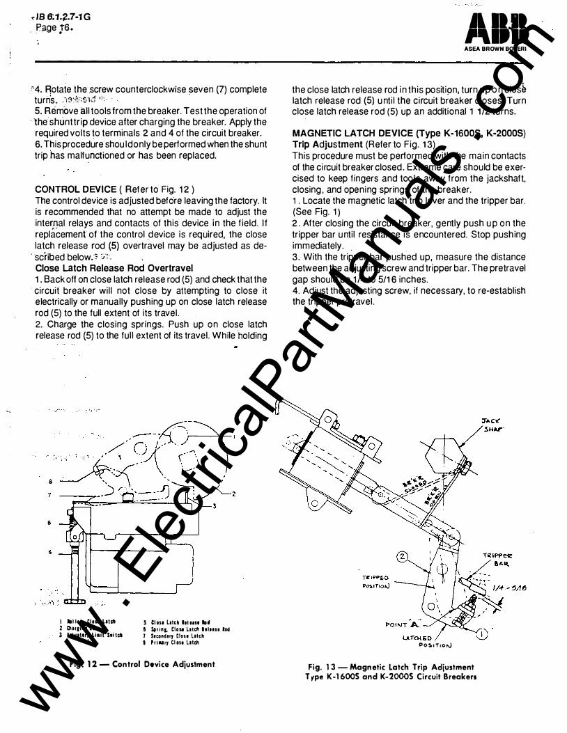
SHUNT TRIP DEVICE Trip Adjustment Type K-225 thru K-2000, K-1 600S, K 2000S (Refer to Fig . 1 0) 1 . Perform th is procedure only on an open c i rcuit breake with its closing springs discharged . 2. Locate t he shunt trip adjust ing screw. See Figure 1 0 i r IB 6. 1 .2.7. - 1 . 3. Rotate the adjusting screw counterclockwise unti l it is no possible to turn it further, DO !"JOT FORCE . 4 . Rotate the screw clockwise three (3) ful l turns then stop 5. Remove all tools from the breaker. Test the operation o the shunt t rip device after charging and closing the breaker Apply the required voltage to terminals 2 and 4 of the circu i breaker secondary disconnects. 6. This procedure should only be performed when the shun t rip has malfunctioned or been replaced.
Trip Adjustment Type K-600S, K-800S ( Refer to Fig. 1 1 1 . Perform th is procedure only on an open circu it breake with its closing springs discharged. 2. Locate the shunt tr ip adjusting screw. 3. Rotate the screw clockwise u nti l it is not possible to t u rr it further, DO NOT FORCE.
www . El
ectric
alPar
tMan
uals
. com
dB 6:1 .. �.7-1 G , Page ys.
'"'4. Rotate the screw counterclockwise �even (7) complete turn's . . Y3:-t;'.tKi .; . 5. Remove all tools from the breaker. Test the operation of 'the shunt trip device after charging the breaker. Apply the required volts to terminals 2 and 4 of the circuit breaker. 6. This procedure shou ldonly be performed when the shunt trip has malfunctioned or has been replaced.
CONTROL DEVICE { Refer to Fig. 1 2 ) The control device is adjusted before leaving the factory. It is recommended that no attempt be made to adjust the internal relays and contacts of this device in the field. If replacement of the control device is required, the close latch release rod {5) overtravel may be adjusted as de-
. scribed below.·; :,;::. Close Latch Release Rod Overtravel 1 . Back off on close latch release rod (5) and check that the
· circuit breaker will not close by attempting to close it electrically or manually pushing up on close latch release rod (5) to the full extent of its travel. 2. Charge the closing springs. Push up on close latch release rod {5) to the ful l extent of its travel. While holding
I lrll lu, Clou Llldt 2 Olaraina C• 3 ktwator, Liait S.i ldl
5 Cl DSI latch II IIIII lrld
I S!lr inL Clou lllcll ltluu lod 1 S.cond11y Closa latch
I P r i aa ry Cl osa latdl
Fig. 1 2 - Control Device Adjustment
Alii ASEA BROWN BOVERI
the close latch release rod i n this positi!)n, turn up o n clos� latch release rod (5) u ntil the circuit breaker closes. Turn close latch release rod (5) up an additional 1 1./2 turns.
MAGNETIC LATCH DEVICE (Type K-16005, K-20005) Trip Adjus tment (Refer to Fig. 1 3) This procedure must be performed with the main contacts of the circuit breaker closed. Extreme care should be exercised to keep fingers and tools away from the jackshaft, closing , and opening springs of the breaker. 1. Locate the magnetic latch trip lever and the tripper bar. (See Fig. 1 } 2 . After closing the circu it breaker, gently push u p on the tripper bar until resistance is encountered. Stop pushing immediately . . 3. With the tripper bar pushed up, measure the distance between the adjusting screw and tripper bar. The pre travel gap should be 1 /4 to 5/1 6 inches. 4. Adjust the adjusting screw, if necessary, to re-establish the tripper pretravel.
P05.tT rol\,)
Fig. 1 3 - Magnetic Latch Trip Adjustment T ,-pe K-1 6005 and K-20005 Circuit Breakers
www . El
ectric
alPar
tMan
uals
. com
I , .....,_)
\_ -::" --
1 8 6.1.2.7-1 G : Page 1 7
'-� " I
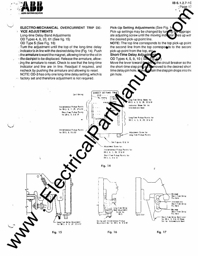
ELECTRO-MECHANICAL OVERCURRENT TRIP D EVICE ADJUSTMENTS
Pick-Up Setting Adjustments (See Fig. 1 4)
Long-time Delay Band Adjustments 00 Types 4, 6, 20, 61 (See fig. 1 5) 00 Type 5 (See Fig. 1 6)
Pick-up sett ings may be changed by turning the appropri ate adjusting screw u ntil the moving indicator l ines up witr the desired pick-up point l ine.
Turn the adjustment u nti l the top of the long-time delay , indicator.is in line with the desired delay line (Fig. 1 4) . Push :· the armature toward the magnet, allowing t ime for the oi l in
- ! tfle dashpot to be displaced. Release the armature, allowdng the armature to reset. Check to see that the long-time
NOTE: The top l ine corresponds to the top pick-up point the second line from the top corresponds to the secane pick-up point from the top, etc. Short-Time Delay Adjustment 00 Types 4, 5, 9, 1 0 ( See Fig. 1 7 )
indicator and line are i n l ine. Readjust if required , and recheck by pushing the armature and allowing to reset. NOTE: 00-3 has only one long-time delay setting; which is factory set and therefore adjustment is not required .
Move the lever toward the left of the circuit breaker so tha the short-time step pin can be moved to the desired short time delay pin hole. Make certain the step pin drops into thE pin hole.
0
DIRECT AC TING TRIP O D . • -
. _ Lon&·! ••• D•I •J lands I c o -· ---._ �"'_"� �o:_.•:; 1
l n s r an l lntous P1 ckup Po t n t s _ _ _ l n l t rMdt .l1 t Band - �- - - - · ;.."... . ) l n d t t J t o r ShoMl Set t o r l
, . E Q '"'� OO·J. 4. 5. 6. 10. J2 L 61
l o r
�;:���:�:�.;��P��.� ... �.:- t'�'=:: ,-�_ ... :_. ,� , o.., G ' '�"'�E 1
r n s t Ml U neous P t ckup Po t n t s / l o • 00·5. 8. 9 ' 82
..., .... lonr·fuae P 1 ckup Po r n t s l o r OO· l. 4 . 5 . 6 . 20 . l2 L 6 1
l" f o ltJ O OS I J L 1 4
ldJuS IMtn l Sc rew l o r lon&� l t •e P • ckug Por n ! s
Ad t us tmrnt S:rt• l o r .
l n s t M� I M� tous P r ckup P o r n t s l o r
00-J. 6 . ), 20. l l ' 6 1 Sho r t · T t Mt P r ckup Po t n l s l o 1
0 0 · 4 . 5 . 9 L 10
Fig. 1 4 :
,..---y-·--v--'.-- l r n r -...
Fig. 1 5
ip r r nt .lnd l n S I Mi l lntous '• ckup ld , u s r m o n l •ul lo• 00-5. I. 9 ' II
Fig. 1 6
Sho , r - r ,., Or I ay P r n H o i t
u-·�-t:-- l n l !' llltd l i ! t Sho r l · l • •• Oo l >y ' ' " llo l o
-T"""'�- IH t i'IJII Sho r t · f,,., De t ar P t n Hoi r
Stlo i ! · T n M Or l ar h:u:l Lt• t r l o r 00· 4 . 5 . 9 L 1 0 Sho"" S e r lor l n l t r •d r .J U hnd
Fig. 1 7
www . El
ectric
alPar
tMan
uals
. com
\
j !
,, . • JB 6.1.2.7·1G Page �'8
• • · • . I' • •
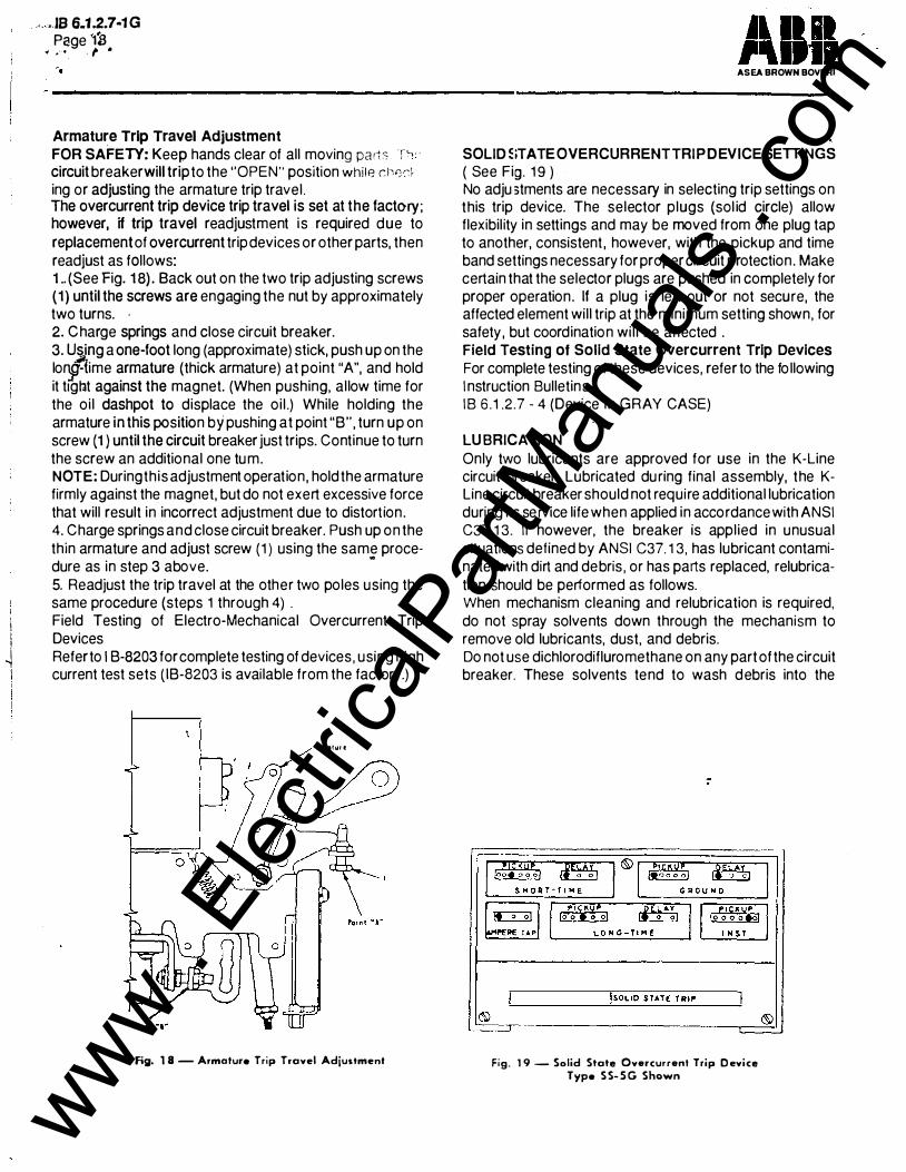
Armature Trip Travel Adjustment FOR SAFETY: Keep hands clear of all moving pan ::: T"' circuit breaker will trip to the "OPEN" position while rl><c,c�\ ing or adjusting the armature trip travel . The overcurrent trip device trip travel is set at the factory; however, if trip travel readjustment is required due to replacement of overcurrent trip devices or other parts, then readjust as follows: 1 .. (See Fig. 1 8) . Back out on the two trip adjusting screws (1 ) until the screws are engaging the nut by approximately two turns. -2. Charge springs and close circuit breaker. 3. Using a one-foot long (approximate) stick, push up on the lo�1ime armature (thick armature) at point "A", and hold it t1gllt against the magnet. (When pushing, allow time for the oi l dashpot to displace the oi l .) While holding the armature in this position by pushing at point "B", turn up on screw (1 ) until the circuit breaker just trips. Continue to turn the screw an additional one tum. NOTE: During this adjustment operation , hold the armature firmly against the magnet, but do not exert excessive force that will result in incorrect adjustment due to distortion . 4. Charge springs and close circuit breaker. Push up on the thin armature and adjust screw ( 1 ) using the same proce-dure as in step 3 above.
..
5. Readjust the trip travel at the other two poles using the same procedure (steps 1 through 4) . Field Testing of Electro-Mechanical Overcurrent Trip Devices Refer to I B-8203 for complete testing of devices , using high current test sets ( IB-8203 is available from the factory.)
lriiiAIUI t
Fig. 1 8 - Armature Trip Travel Adjustment
ASEA BROWN BOVERI
SOLID �iTATE OVERCURRENTTRIPDEVICE SETTINGS ( See Fig. 1 9 ) No adju :>tments are necessary in selecting trip settings on this trip device. The selector plugs (sol id circle) allow flexibil ity in settings and may be moved from one plug tap to another, consistent , however, with the pickup and time band settings necessary for proper circuit protection . Make certain that the selector plugs are pushed in completely for proper operation . If a plug is left out or not secure, the affected element will trip at the minimum setting shown, for safety , but coordination wil l be affected . Field Testing of Solid State Overcurrent Trip Devices For complete testing of these devices, refer to the fo llowing I nstruction Bulletins IB 6 . 1 .2.7 - 4 (Device in GRAY CASE)
LU BRICATION Only two lubricants are approved for use in the K-Line circuit breaker. Lubricated du ring final assembly, the KLine circuit breaker should not require additional lubrication during its service life when applied in accordance with ANSI C37. 1 3. If however, the breaker is applied in unusual s ituations defined by ANSI C37. 1 3, has lubricant contaminated with dirt and debris , or has parts replaced, relubrication should be performed as follows. When mechanism cleaning and relubrication is required, do not spray solvents down through the mechanism to remove old lubricants, dust, and debris. Do not use dichlorodifluromethane on any part of the circuit breaker. These solvents tend to wash debris into the
Fig. 1 9 - Solid State Overcurrent Trip D evice Type S S- S G Shown
www . El
ectric
alPar
tMan
uals
. com
v
. ASEA BROWN BOVERI
. ; bearing areas of the breaker, while at the same time removing any existing lubricant. ·Breaker performance will be compromised when these cleaning techniques are employed. Properrelubrication requires disassembly, thorough cleaning by wiping, then reassembly using a brush or other means for reapplying the lubricants listed. 1 .. �pply NO-OX-ID special grade" A" grease from Dearborn Chemical Company to all mating surfaces of moving current carrying joints. Do not apply NO-OX-ID grease on any main o r arcing contact surface. Primary disconnects should be maintained by reapplying NO-OX-I D during maintenance periods. NO-OX- ID is available from Asea Brown
. . Boveri in one pint cans, number 71 3222-A. 2. Apply Andersol 757 synthetic grease manufactured by HULS AMERICA, INC. to mechansim parts, bearings and pins. DO NOT APPLY. GREASE TO LATCH OR ROLLER SURFACES. Andersol 757 is available from Asea Brown Boveri in four ounce tubes, part number 71 2994-A. 3. Andersol synthetic lubricant is also available as a spray, Andersol 732. Andersol 732 is usefu l as a solvent for removing old lubricant, dirt, and debris in the mechanism. It cannot be used as a substitute for Anderol 757. Please observe the following warnings : 1 . DO NOT apply light machine oil , or th in spray lubricants
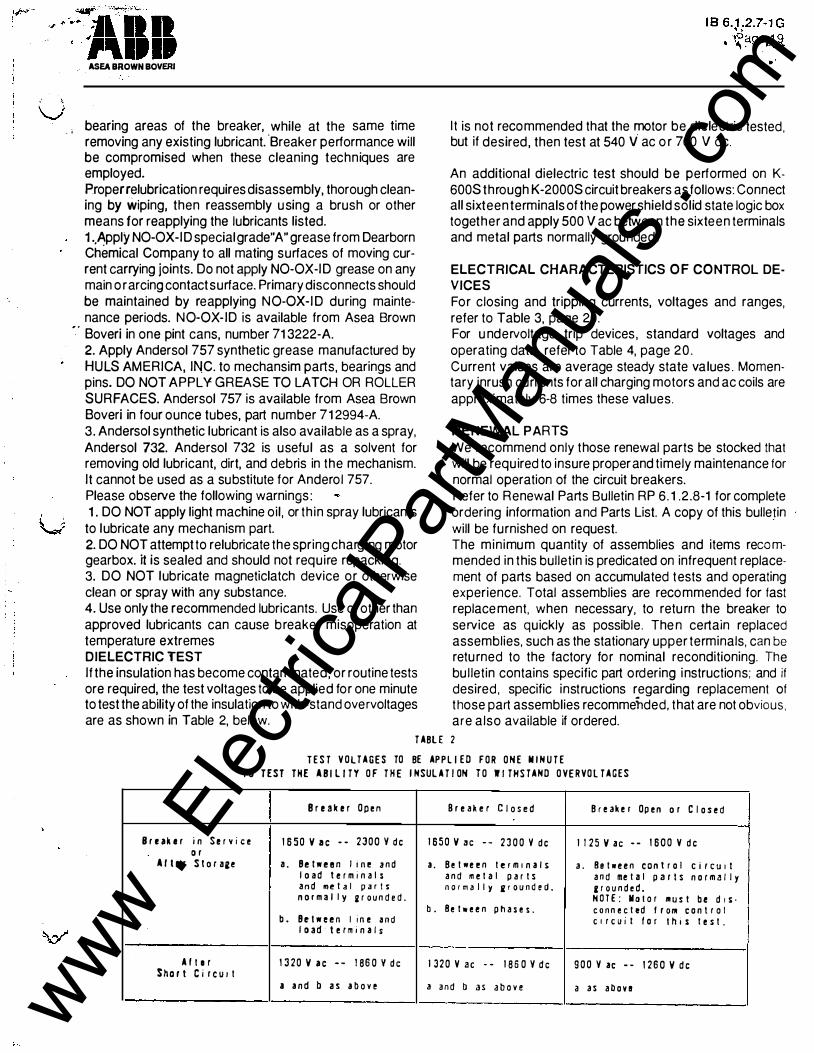
to lubricate any mechanism part. 2. DO NOT attempt to relubricate the spring charging motor gearbox. it is sealed and should not require repacking. 3. DO NOT lubricate magneticlatch device or otherwise clean or spray with any substance. 4. Use only the recommended lubricants. Use of other than approved lubricants can cause breaker misoperation at temperature extremes DIELECTRIC TEST I f the insulation has become contaminated, or routine tests ore required, the test voltages to be applied for one minute to test the ability of the insulation to with-stand overvoltages are as shown in Table 2, below.
I t is not recommended that the motor be dielectric tested , but if desired , then test at 540 V ac o r 760 V de.
An additional dielectric test should be performed on K-600S through K-2000S circuit breakers as follows: Connect all sixteen terminals of the power shield solid state logic box together and apply 500 V ac between the sixteen terminals and metal parts normally grounded .
ELECTRICAL CHARACTERISTICS OF CONTROL DE· VICES For closing and tripping currents, voltages and ranges, refer to Table 3, page 20 . For u ndervoltage trip devices , standard voltages and operating data, refer to Table 4, page 20. Current values are average steady state va lues . Momentary inrush currents for all charging motors and ac coils are approximately 6-8 times these values.
RENEWAL PARTS We recommend only those renewal parts be stocked that will be required to insure proper and timely maintenance for normal operation of the circuit breakers. Refer to Renewal Parts Bulletin RP 6. 1 .2 .8-1 for complete ordering information and Parts List. A copy of this bulleJin will be furnished on request. The minimum quantity of assemblies and items recommended in this bulletin is predicated on infrequent replacement of parts based on accumulated tests and operating experience. Total assemblies are recommended for fast replacement, when necessary, to retu rn the breaker to service as quickly as possible. The n certain replaced assemblies, such as the stationary upper terminals, can be retu rned to the factory for nominal reconditioning. The bu l letin contains specific part ordering instructions; and if desired , specific instructions regarding replacement of those part assemblies recommehded, that are not obvious, are also available if ordered.
T ABL E 2
T E S T V O L T A G E S TO BE AP P L I E D F O R O N E M I N U T E
T O T E S T T H E A B I L I T Y O F T H E I NSUL A T I ON T O W I T H S TAND O VE R VO L T A G E S
B r e a k e r O p e n B r e a k e r C l o s e d B r e ak e r Op e n o r C I o s e d
B r e ak e r i n S e r v i c e 1 6 5 0 V a c - - 2 3 0 0 V d e 1 6 5 0 V a c - - 2 3 0 0 V d e 1 1 2 5 V a c - - 1 6 0 0 V d e o r
A I t e r S t o r a2e a. Be t w e e n I i n e a n d a . B e t ,., e e n t e r m 1 n a l s a . B e t • e e n c o n t r o l C i r C U I I I o a d t e r m 1 n a l s a n d m e t a l p a r t s a n d me t a l p a r 1 s n o r m a l l y a n d me t a I p a r t s n o r m a l l y j p o u n d e d . e r o u n d e d . n o r m a l l y 2 r o u n d e d . H O T £ : lla t o r III U S t b e d i S ·
b . B e t ,., e e n p h a s e s . c o n n e c t ed f r o 111 c o n t r o l b . Be t w e e n I i n e a n d C i r C U l i I o r t h i s t e s t .
I o ad t e r m 1 n a l s
A I t e r 1 3 2 0 V a c - - 1 86 0 Y d c I 3 2 0 V a c - - 1 8 6 0 V d c 9 0 0 V ac - - 1 2 6 0 V d e S h o r t C i r c u 1 t
a a n d b a s a b o v e 3 a n d b a s a b o v e a a s a b o v e www . El
ectric
alPar
tMan
uals
. com