Embed Size (px)
Citation preview

1
INSTALLATION INSTRUCTIONSDesigner Series BUILT-IN chimney-style HOODS
VIKING RANGE CORPORATION111 FRONT STREET
GREENWOOD, MISSISSIPPI 38930 USA(662) 455-1200
NOTE: IF INSTALLING HOOD WITH WARMING SHELF PANEL, INSTALL WARMING SHELF PANEL FIRST.
IMPORTANT - PLEASE READ AND FOLLOW•Before beginning, please read these instructions completely and carefully.•Do not remove permanently affixed labels, warnings, or plates from the product. This may void the warranty.•Please observe all local and national codes and ordinances. If no local codes are applicable, wire in accordance with theNational Electrical Code, ANSI/NFPA 70-latest edition.
••CChheecckk wwiitthh aa qquuaalliiffiieedd aanndd ttrraaiinneedd iinnssttaalllleerr oorr llooccaall ccooddeess ffoorr mmaakkeeuupp aaiirr rreeqquuiirreemmeenntt,, iiff aannyy..•The installer should leave these instructions with the consumer who should retain for local inspector’s use and for futurereference.
This hood is for residential installation only and is not designed for installation over a commercial product. Make sure power is offat the main circuit breaker or fuse box before making connections. To avoid risk of fire, electric shock, or injury to persons,turn off the electricity to the hood from the power supply before servicing or cleaning.
Viking hoods are equipped with variable speed controls for blowers. These units will not function with a single speedventilator. All Viking Range ventilator kits are designed specifically for use with Viking Range hoods. Use of any non-VikingRange ventilator kit will void the hood warranty.
WARNINGTO REDUCE THE RISK OF FIRE, ELECTRICAL SHOCK, OR INJURY TO PERSONS, OBSERVE THE FOLLOWING:
1. Installation work and electrical wiring must be done by qualified person(s) in accordance with all applicable codesand standards, including fire-rated construction.
2. Sufficient air is needed for proper combustion and exhausting of gases through the flue (chimney) of fuel burningequipment to prevent back drafting. Follow the heating equipment manufacturer’s guideline and safety standardssuch as those published by the National Fire Protection Association (NFPA), and the American Society for Heating,Refrigeration and Air Conditioning Engineers (ASHRAE), and the local code authorities.
3. When cutting or drilling into wall or ceiling, do not damage electrical wiring and other hidden utilities.4. Ducted fans must always be vented to the outdoors.5. WARNING!!:: To reduce the risk of fire, use only metal ductwork.6. CAUTION!!:: To reduce risk of fire and to properly exhaust air, be sure to duct air outside. Do not vent exhaust
air into spaces within walls or ceilings, or into attics, crawl spaces, or garages.
CAUTIONFor general ventilating use only. Do not use to exhaust hazardous or explosive materials and vapors.
WARNINGTO REDUCE THE RISK OF FIRE, ELECTRICAL SHOCK, OR INJURY TO PERSONS, RANGEHOODS MUST BEINSTALLED WITH THE VENTILATORS THAT ARE SPECIFIED ON THEIR CARTON INDICATING SUITABILITYWITH THIS MODEL. OTHER VENTILATORS CANNOT BE SUBSTITUTED.
WARNINGTO REDUCE THE RISK OF A RANGETOP GREASE FIRE:1. Never leave surface units unattended at high setting. Boilovers cause smoking and greasy spillovers
that may ignite. Heat oils slowly on low or medium settings.2. Always turn hoon ON when cooking at high heat or when cooking flaming foods.3. Clean ventilating fans frequently. Grease should not be allowed to accumulate on fan or filter.4. Use proper pan size. Always use cookware appropriate for the size of the surface element.

BASIC SPECIFICATIONSINTERIOR AND EXTERIOR POWER HOODS
RREECCOOMMMMEENNDDEEDD MMAAXX.. DDUUCCTT
MMOODDEELL NNUUMMBBEERR CCFFMM11 DDUUCCTT SSIIZZEE RRUUNN22 ((fftt..))FFoorr UUssee wwiitthh hhooooddss::
DIV300 (interior) 300 7” round 50
DIV440 (interior) 440 7” round 50
DIV600 (interior) 600 7” round 50
DIV1200 (interior) 1200 10” round 50
DEV900 (exterior) 900 10” round 50
DEV1200 (exterior) 1200 10” round 50
DEV1500 (exterior) 1500 10” round 75
PROPER INSTALLATION/DUCTING IS EXTREMELY IMPORTANT TO ENSURE MAXIMUM PERFORMANCE FROM ANYVENTILATION PRODUCT
1. •All CFMs stated are based on tests at .1 static pressure: without applying static pressure, CFM would be greatlyoverstated.
2. •Duct run length is for general reference only; for longer duct runs, increase duct size and contact a qualified and trainedinstaller.
•Straight runs and gradual turns are best; for example, each 90o elbow is equivalent to 5-10 feet (1.52 - 3.05 cm) ofstraight run.
•Never use flexible duct; it creates back pressure/air turbulence and greatly reduces performance. •Proper performance is dependent upon proper ducting; make sure that a qualified and trained installer is used.••CChheecckk wwiitthh aa qquuaalliiffiieedd aanndd ttrraaiinneedd iinnssttaalllleerr oorr llooccaall ccooddeess ffoorr mmaakkeeuupp aaiirr rreeqquuiirreemmeenntt,, iiff aannyy..
3. •Max. amp rating for hoods includes recommended ventilator kit rating; all products must be hard wired direct with 2-wire with ground.
**11220000 CCFFMM ((oorr 11550000 CCFFMM iiff aapppplliiccaabbllee)) eexxtteerriioorr vveennttiillaattoorr sshhoouulldd bbee uusseedd wwhheenn iinnssttaalllleedd oovveerr rraannggeess//rraannggeettooppss wwiitthhggaass ggrriillll..
RREECCOOMM.. NNUUMMBBEERR OOFF 112200VVAACC//6600HHzzDDEESSCCRRIIPPTTIIOONN CCFFMM11 HHAALLOOGGEENN FFIILLTTEERRSS SSPPAACCEERRSS MMAAXX.. AAMMPPSS33
((iinntt..--iinntteerriioorr;; eexxtt--eexxtteerriioorr LLIIGGHHTTSS ((IInntteerriioorr//EExxtteerriioorr))
30”W. 300 int,/440 int./900 ext./1200 ext. 2 2 0 1.7/3.2/6.6/3.936”W.* 300 int./600 int./900 ext./1200 ext. 2 2 1 1.7/3.9/6.6/3.942”W.* 600 int./900 ext./1200 ext. 2 3 0 3.9/6.6/3.948”W. 1200 int./1200 ext./1500 ext. 3 3 0 7.3/4.3/5.1
WWaallll HHooooddss
RREECCOOMM.. NNUUMMBBEERR OOFF 112200VVAACC//6600HHzzDDEESSCCRRIIPPTTIIOONN CCFFMM11 HHAALLOOGGEENN FFIILLTTEERRSS SSPPAACCEERRSS MMAAXX.. AAMMPPSS33
((iinntt..--iinntteerriioorr;; eexxtt--eexxtteerriioorr LLIIGGHHTTSS ((IInntteerriioorr//EExxtteerriioorr))
36”W.* 600 int./900 ext./1200 ext. 4 2 1 3.9/6.6/3.9
42”W.* 600 int./900 ext./1200 ext./1500 ext. 4 2 1 4.7/7.4/4.8/5.5
54”W. 1200 int./1200 ext./1500 ext. 6 3 2 8.6/5.6/6.4
IIssllaanndd HHooooddss
2

3
HEIGHT OF HOODThe bottom of the hood to should be 30” (76.2 cm) min. to 36” (91.4 cm) max above the countertop. This
would typically result in the bottom of the hood being 66” (167.6 cm) to 72” (182.9 cm) above the floor. For bestperformance, it is recommended that the bottom of the hood be 30” (76.2 cm) to 33” (83.8 cm) above thecountertop. These dimensions provide for safe and efficient operation of the hood.
ISLAND INSTALLATIONWALL INSTALLATION
CookingSurface
CookingSurface
30” W. Models- 12” (30.5 cm)
All other models-14” (35.6 cm)
14” (35.6 cm)
30” (76.2 cm) min36” (91.4 cm) max
30” (76.2 cm) min36” (91.4 cm) max
36” (91.4 cm)
36” (91.4 cm)

INSTALLING HOOD CANOPY(Before installing island hood canopy - skipto page 5)Center the canopy and attach to wall. Securethe hood to wall with mounting screwsprovided. Make sure that the mounting screwsare driven into the framing and not just thedrywall. Use additional mounting screws (andwall anchors if necessary) in the other holes.
NOTE: BECAUSE OF THE WEIGHT OF THEHOOD - MAKE SURE THAT THE MOUNTINGSCREWS ARE DRIVEN INTO THE FRAMINGAND NOT JUST THE DRYWALL. IT MAY BENECESSARY TO DRILL ADDITIONAL HOLESIN THE CANOPY FOR PROPER ALIGNMENT.
4
PREPARING FOR HOOD INSTALLATIONPlan where the ductwork will be located. See pages 11-14 for rough-in dimensions. Install proper-sized duct work,and roof or wall cap for the type of blower you are using. Recommended hood locations for the most commoninstallations are shown on page 2. Adjust your measurements for various heights of ceilings, soffits, cabinets, or ranges/rangetops.
Roof Cap
10” RoundDuct
1200 CFM SingleBlower
Interior-Power -Typical Ductwork
Exterior Blower
10” RoundDuct
12” DuctCover
or Soffit
900, 1200, or1500 CFM
Exterior-Power -Typical Ductwork
ELECTRICAL SUPPLYRun 120 VAC electrical power cable from service panel to installation location. See “Basic Specifications” on page 15for the maximum amp requirements.
Top Mounting Holes(Soffit or duct cover)
12” Duct Coveror Soffit
Roof Cap
7” RoundDuct
600 CFM SingleBlower
Interior-Power -Typical Ductwork
Duct Coveror Soffit
Roof Cap
7” RoundDuct
300 or 440 CFMSingle Blower
Interior-Power -Typical Ductwork
Duct Coveror Soffit

5
INSTALLING THE DUCT COVER (wall hoods only)1. Measure from top of the canopy to ceiling and subtract 1/8” (0.3 cm) for clearance.2. Place the duct cover top inside the duct cover base and lower until desired height is found. (To eliminate
scratches, make a mark on the duct cover top for the desired lowering point by subtracting 18” (45.7 cm) from thetotal height needed.)
3. Use the retaining nuts and bolts to fasten in place.4. Slide the duct cover in place and fasten from inside canopy using the sheet metal screws provided.5. Note: For installations with ceilings above 9’ (22.9 cm), use optional duct extensions. See product literature for
details
Item 1
C
12” (30.5 cm)
DuctCover Top
Duct CoverBase
Item 2
AMin
BMax
Item 4
Item 3
Canopy Top
Model “A” Min. “B” Max “C”DCWH3042 18” (45.7 cm) 30” (76.2 cm) 10” (25.4 cm)DCWH3644 16” (40.6 cm) 28” (71.1 cm) 12” (30.5 cm)DCWH4244 16” (40.6 cm) 28” (71.1 cm) 12” (30.5 cm)DCWH4844 16” (40.6 cm) 28” (71.1 cm) 18” (45.7 cm)
DCWL3342 18” (45.7 cm) 30” (76.2 cm) 10” (25.4 cm)DCWL3944 16” (40.6 cm) 28” (71.1 cm) 12” (30.5 cm)DCWL4544 16” (40.6 cm) 28” (71.1 cm) 12” (30.5 cm)DCWL5144 16” (40.6 cm) 28” (71.1 cm) 18” (45.7 cm)
DCWN3042 18” (45.7 cm) 30” (76.2 cm) 10” (25.4 cm)DCWN3644 16” (40.6 cm) 28” (71.1 cm) 12” (30.5 cm)DCWN4244 16” (40.6 cm) 28” (71.1 cm) 12” (30.5 cm)DCWN4844 16” (40.6 cm) 28” (71.1 cm) 18” (45.7 cm)

6
INSTALLING THE optional DUCT COVER (island hoods only)
1. Cut hole in ceiling for correct diameter duct. 2. Attach duct cover/soffit to ceiling. Make sure there is enough support in the ceiling to support at least 200 lbs.
(Center duct cover/soffit with duct opening)3. Run duct work down to bottom edge of duct cover/soffit and secure in place. (Make sure the duct does not stick
down past the cover/soffit.)4. Attach duct cover/soffit to the top of the canopy with nuts and bolts provided. (Additional support can be added
by running threaded rod from the ceiling to the top of the canopy at all four corners using the holes provided.)5. Install blower (see ventilator kit installation).
A B
12”(30.5 cm)6”(15.3 cm)
C2
1
4
3
Holes for threaded rod (4)
CanopyTop
36”W. / 42”W. 54”W.A 12” (30.5 cm) 18” (45.7 cm)B 6” (15.3 cm) 9” (22.7 cm)C 16” (40.6 cm), 16” (40.6 cm),
28” (71.1 cm), or 28” (71.1 cm), or40” (101.6 cm) 40” (101.6 cm)
Duct Cover/Soffit

7
ventilator kit installationDiV300 (Also see instructions supplied with
ventilator kit)
1. Attach DAMPER to VENTILATOR, as shown,using three (3) HEX SCREWS (provided). Note:Damper flange to be captured by screw heads.
2. Attach VENTILATOR to (4) THREADED STUDSon MOUNTING PLATE using (4) HEX NUTS(provided).
3. Lift ventilator into position inside the hood.4. Fasten ventilator to four (4) THREADED STUDS,
using four (4) HEX NUTS (provided).5. Plug ventilator's POWER CORD into
RECEPTACLE inside the hood.
ventilator kit installationDiV440 (Also see instructions supplied with ventilator
kit)
1. Attach DAMPER to VENTILATOR, as shown, using three(3) HEX SCREWS (provided). Note: Damper flange to becaptured by screw heads.
2. Lift ventilator into position inside the hood.3. Fasten ventilator to four (4) THREADED STUDS, using
four (4) HEX NUTS (provided).4. Plug ventilator's POWER CORD into RECEPTACLE inside
the hood.5. NOTE: This installation does not use the mounting
plate and (4) additional hex nuts. They may bediscarded.
8
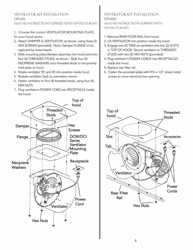
ventilator kit installation DiV600 (Also see instructions supplied with ventilator kit)
1. Choose the correct VENTILATOR MOUNTING PLATEfor your hood series.2. Attach DAMPER to VENTILATOR, as shown, using three (3)
HEX SCREWS (provided). Note: Damper FLANGE to becaptured by screw heads.
3. Slide mounting plate/damper assembly into hood and ontofour (4) THREADED STUDS, as shown. Slide four (4)NEOPRENE WASHERS onto threaded studs to temporarilyhold plate to hood.
4. Rotate ventilator 90o and lift into position inside hood.5. Roatate ventilator back to orientation shown.6. Fasten ventilator to four (4) threaded studs, using four (4)
HEX NUTS.7. Plug ventilator's POWER CORD into RECEPTACLE inside
the hood.
TThhrreeaaddeeddSSttuuddss
NNeeoopprreenneeWWaasshheerrss
DDCCWW//DDCCIISSeerriieessVVeennttiillaattoorrMMoouunnttiinnggPPllaattee
FFllaannggee
TToopp ooffhhoooodd
HHeexxSSccrreewwss
DDaammppeerr
RReecceeppttaaccllee
PPoowweerr CCoorrdd
VVeennttiillaattoorr
HHeexx NNuuttss
ventilator kit installationDiV1200(Also see instructions supplied with
ventilator kit)
1. Remove REAR FILTER RAIL from hood.2. Lift VENTILATOR into position inside the hood.3. Engage two (2) TABS on ventilator into two (2) SLOTS
in TOP OF HOOD. Secure ventilator to THREADEDSTUDS with two (2) HEX NUTS (provided).
4. Plug ventilator's POWER CORDS into RECEPTACLESinside the hood.
5. Replace rear filter rail.6. Fasten the provided plate with #10 x 1/2” sheet metal
screws to cover electrical box opening.
TThhrreeaaddeeddSSttuuddss
TToopp ooffhhoooodd
RReecceeppttaacclleess
PPoowweerrCCoorrddss
VVeennttiillaattoorr
HHeexx NNuuttss
RReeaarr FFiilltteerrRRaaiill
SSlloott
TTaabb
9
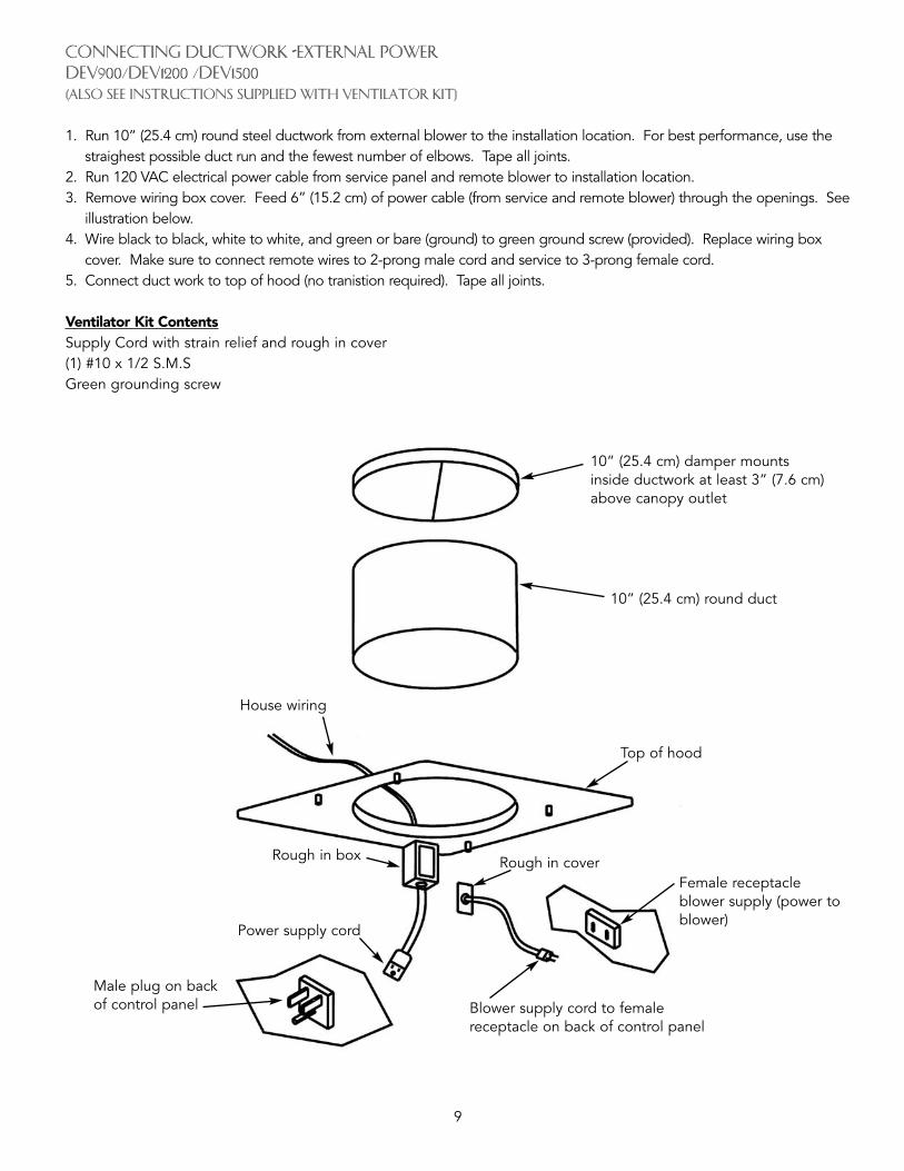
CONNECTING DUCTWORK -EXTERNAL POWERDEV900/DEV1200 /DEV1500 (Also see instructions supplied with ventilator kit)
1. Run 10” (25.4 cm) round steel ductwork from external blower to the installation location. For best performance, use thestraighest possible duct run and the fewest number of elbows. Tape all joints.
2. Run 120 VAC electrical power cable from service panel and remote blower to installation location.3. Remove wiring box cover. Feed 6” (15.2 cm) of power cable (from service and remote blower) through the openings. See
illustration below.4. Wire black to black, white to white, and green or bare (ground) to green ground screw (provided). Replace wiring box
cover. Make sure to connect remote wires to 2-prong male cord and service to 3-prong female cord.5. Connect duct work to top of hood (no tranistion required). Tape all joints.
Ventilator Kit ContentsSupply Cord with strain relief and rough in cover(1) #10 x 1/2 S.M.SGreen grounding screw
10” (25.4 cm) damper mountsinside ductwork at least 3” (7.6 cm)above canopy outlet
10” (25.4 cm) round duct
House wiring
Top of hood
Female receptacleblower supply (power toblower)
Rough in cover
Blower supply cord to femalereceptacle on back of control panel
Rough in box
Power supply cord
Male plug on backof control panel

ROOF INSTALLATION EXTERIOR-POWER VENTILATOR DEV900-Exterior Power Ventilator Kit (900CFM)(also see instructions supplied with ventilator kit)1. Locate the blower on the rear slope of the roof. Place it
in a location to minimize duct run. The location shouldbe free of obstacles (T.V. leads, electrical lines, etc.).Bear in mind, if the blower top is level with the roofpeak, it will not be seen from the street. Keep thisapproximate location in mind as you work from withinthe attic.
2. Mark a point halfway between rafters.3. Drill a guide hole through the roof at this point. 4. From the outside, use the guide hole as a starting
point.A. Use a T-square to measure 81/2” (21.6 cm) to the
left of the guide hole, then down 103/8” (26.4 cm)to locate the bottom left corner of the layout.
B. Mark the rectangular cutout and remove only theshingles in this area.
5. Mark an 11” (27.9 cm) diameter circle centered on theguide hole and mark the center of the 11/4” (3.2 cm)diameter electrical wiring hole.
6. Cut out the roof board(s) along the 11” (27.9 cm)diameter circle and drill a 11/4” hole as marked.
7. For flat roof installations, build a curb that will mount theblower at a minimum pitch of 2/12. Discharge end ofthe blower should be pointed away from prevailingwinds.
8. Remove roofing nails from the upper two-thirds of theshingles around the cutout area. Carefully lift theshingles to allow the back flashing sheet on the blowerhousing to fit under them.
9. Center the blower ring in the 11” (27.9 cm) diameterhole, making sure that the 11/4” (3.2 cm) diameterelectrical wiring hold aligns with the hole in the wiringbox.
10. Attach the blower to the roof with the six screwsprovided. It is recommende that the screws be locatedinside the blower housing. All six holes in the backpanel must be filled, or any moisture that may getinside the housing could leak into the house.
11. Using a good grade of roofing cement, seal all of theshingles around the housing and flashing sheet as wellas the mounting screw heads.
12. Bring electrical wiring through the hole in the wiringbox and secure it according to local codes.
13. Make the electrical connections with the properconnector for the type of wiring being used. Connectwhite to white, black to black, and the green or barewire to green.
14. Replace wiring box cover and screws. Do not pinchwiring under the cover.
15. Check for free movement of the damper beforeinstalling housing cover and screws.
16. Turn on power and check operation of the blower.
GuideHole
11” (27.9 cm)dia. hole
71/4” (18.4 cm)
11/4” (3.2 cm) dia. hole
81/2” (21.6 cm)
103/8”(26.4 cm)
201/2”(52.1 cm) 91/8”
(23.2 cm)
203/4” (52.7 cm)
2”(5.1 cm)
2”(5.1 cm)
7” (17.8 cm)
291/2”(74.9 cm)
25”(63.5 cm)
RROOOOFF CCUUTTOOUUTT
RREEMMOOVVEE SSHHIINNGGLLEESS
Green toGreen
WhitetoWhite
BlacktoBlack
120 VACLine In
10

11
WALL INSTALLATION EXTERIOR-POWER VENTILATORDEV900-Exterior-Power Ventilator Kit (900CFM)
1. Choose a position on the outside wall. Min. 24” (61.0cm from ground may vary depending on local codesor location. Make sure that no wall studs, pipes orwires run through the opening area.
2. Drill a guide hole at the center of the opening area.3. From the outside, use the guide hole as a starting
point to lay out the installation.A. Use a T-square to measure 103/4” (27.3 cm) to the
left of the guide hole, then 127/8” (32.7 cm) tolocate the top-left corner of the layout.
B. Starting from the top -left corner, mark a 25”(63.5 cm) by 281/2” (72.4 cm) rectangle on walllocated from guide hole.
4. Cut a rectangular hole in the siding only. Do not cutthe sheathing. Nail down all siding ends.
5. Mark an 11” (27.9 cm) diameter circle centered on theguide hole and mark the center of the 11/4” diameterelectrical wiring hole.
6. Cut the 11” (27.9 cm) hole in the sheathing and drillthe 11/4”(3.2 cm) as marked.
7. Place a large bead of caulk on the back side of thehousing along the outer edge.
8. Center the blower ring in the 11” (27.9 cm) diameterhole, making sure that the 11/4” (3.2 cm) diameterelectrical wiring hole aligns with the hole in the wiringbox.
9. Attach blower to the wall with the six screwsprovided. It is recommended that the screwsbe located inside the blower housing. All sixholes in the back panel must be filled, or anymoisture that may get inside the housing couldleak into the house.
10. Using a good grade of caulk, seal all around themounting screw heads.
11. Bring electrical wiring through the hole in thewiring box and secure it according to localcodes.
12. Make the electrical connections with the properconnector for the type of wire being used.Connect white to white, black to black, andgreen or bare wire to green.
13. Replace wiring box cover and screws. Do notpinch wiring under cover.
14. Check for free movement of the damper beforeinstalling housing cover and screws.
15. Turn on power and check operation of the blower.16. Top and side flanges of the back plate may be
covered with trim strips. Do not block grill opening atbottom with trim. It will adversely affect performanceof the blower.
BlacktoBlack
120 VACLine In
WhitetoWhite
Green toGreen
11” (27.9 cm)dia. hole
GuideHole
91/8”(23.2 cm)
71/4” (18.4 cm)11/4” (3.2 cm)Dia. Hole
12 7/8”(32.7 cm)
28 1/4”(71.8 cm)
25” (63.5 cm)103/4”(27.3 cm)
WALL CUTOUT

ROOF INSTALLATIONEXTERIOR-POWER VENTILATORExterior Power Ventilator
(also see instructions supplied with ventilator kit)1. Locate the blower on the rear slope of the roof. Place
it in a location to minimize duct run. The locationshould be free of obstacles (T.V. leads, electrical lines,etc.). Bear in mind, if the blower top is level with theroof peak, it will not be seen from the street. Keepthis approximate location in mind as you work fromwithin the attic.
2. Mark a point halfway between rafters.3. Drill a guide hole through the roof at this point. 4. From the outside, use the guide hole as a starting
point to lay out the installation.A. Use a T-square to measure 913/16” (24.9 cm) to
the left of the guide hole, then 1211/16” (32.2 cm)to locate the top-left corner of the layout.
B. Starting from the top-left corner, mark therectangular cutout and remove only the shingles inthis area.
5. Mark an 11” (27.9 cm) diameter hole centered on theguide hole. Mark the center of the 11/4” (3.2 cm)diameter electrical wiring hole.
6. Cut out the roof board(s) along the 11” (27.9 cm)diameter circle and drill a 11/4” hole as marked.
7. For flat roof installations, build a curb that will mountthe blower at a minimum pitch of 2/12. Dischargeend of the blower should be pointed away fromprevailing winds.
8. Remove roofing nails from the shingles around thetop and sides of the cutout area only. Carefully liftthe shingles to allow the back flashing sheet on theblower housing to fit under them.
9. Center the blower ring in the 11” (27.9 cm) diameterhole, making sure that the 1 ¼” (3.2 cm) diameterelectrical wiring hold aligns with the hole in the wiringbox.
10. Attach the blower to the roof with the six screwsprovided. It is recommended that the screws belocated inside the blower housing. All six holes in theback panel must be filled, or any moisture that mayget inside the housing could leak into the house.
11. Using a good grade of roofing cement, seal all of theshingles around the housing and flashing sheet aswell as the mounting screw heads.
12. Bring electrical wiring through the hole in the wiringbox and secure it according to local codes.
13. Make the electrical connections with the properconnector for the type of wiring being used.Connect white to white, black to black, and the greenor bare wire to green.
14. Replace wiring box cover and screws. Do not pinchwiring under the cover.
15. Check for free movement of the damper beforeinstalling housing cover and screws.
16. Turn on power and check operation of the blower.
20 1/2”(52.1 cm)
BB
12 11/16”(32.2 cm)
AA
CC
11/4” (3.2cm) dia. hole
11” (27.9 cm)dia. hole
RREEMMOOVVEESSHHIINNGGLLEESS
291/2”(74.9 cm)
DD 2” (5.1 cm)
2” (5.1 cm)
7” (17.8 cm)
RROOOOFF CCUUTTOOUUTT
Black toBlack
Ground togrounding
screw
120 VACLine In
12
Whiteto Blue
A B C DDEV1200 18” 15” 9 13/16’ 22”
(45.7 cm) (38.1 cm) (24.9 cm) (55.9 cm)DEV1500 21” 18” 12 5/8” 25”
(53.3 cm) (45.7 cm) (32.1 cm) (63.5 cm)
13
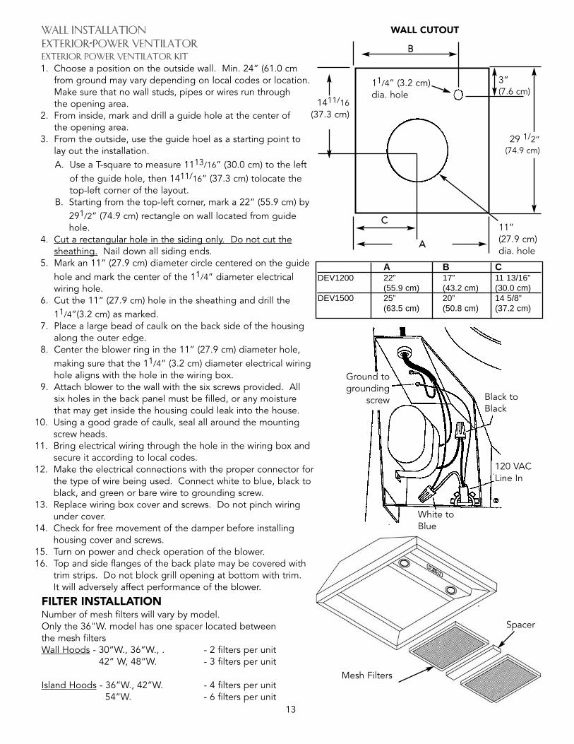
WALL INSTALLATION EXTERIOR-POWER VENTILATORExterior Power Ventilator Kit 1. Choose a position on the outside wall. Min. 24” (61.0 cm
from ground may vary depending on local codes or location.Make sure that no wall studs, pipes or wires run throughthe opening area.
2. From inside, mark and drill a guide hole at the center ofthe opening area.
3. From the outside, use the guide hoel as a starting point tolay out the installation.A. Use a T-square to measure 1113/16” (30.0 cm) to the left
of the guide hole, then 1411/16” (37.3 cm) tolocate thetop-left corner of the layout.
B. Starting from the top-left corner, mark a 22” (55.9 cm) by291/2” (74.9 cm) rectangle on wall located from guidehole.
4. Cut a rectangular hole in the siding only. Do not cut thesheathing. Nail down all siding ends.
5. Mark an 11” (27.9 cm) diameter circle centered on the guidehole and mark the center of the 11/4” diameter electricalwiring hole.
6. Cut the 11” (27.9 cm) hole in the sheathing and drill the11/4”(3.2 cm) as marked.
7. Place a large bead of caulk on the back side of the housingalong the outer edge.
8. Center the blower ring in the 11” (27.9 cm) diameter hole,making sure that the 11/4” (3.2 cm) diameter electrical wiringhole aligns with the hole in the wiring box.
9. Attach blower to the wall with the six screws provided. Allsix holes in the back panel must be filled, or any moisturethat may get inside the housing could leak into the house.
10. Using a good grade of caulk, seal all around the mountingscrew heads.
11. Bring electrical wiring through the hole in the wiring box andsecure it according to local codes.
12. Make the electrical connections with the proper connector forthe type of wire being used. Connect white to blue, black toblack, and green or bare wire to grounding screw.
13. Replace wiring box cover and screws. Do not pinch wiringunder cover.
14. Check for free movement of the damper before installinghousing cover and screws.
15. Turn on power and check operation of the blower.16. Top and side flanges of the back plate may be covered with
trim strips. Do not block grill opening at bottom with trim.It will adversely affect performance of the blower.
WALL CUTOUT
BB
3”(7.6 cm)
1411/16(37.3 cm)
CC
AA
11”(27.9 cm)dia. hole
11/4” (3.2 cm)dia. hole
Black toBlack
120 VACLine In
Ground togrounding
screw
FILTER INSTALLATIONNumber of mesh filters will vary by model.Only the 36"W. model has one spacer located betweenthe mesh filtersWall Hoods - 30”W., 36”W., . - 2 filters per unit
42” W, 48”W. - 3 filters per unit
Island Hoods - 36”W., 42”W. - 4 filters per unit54”W. - 6 filters per unit
29 1/2”(74.9 cm)
Mesh Filters
Spacer
White toBlue
A B CDEV1200 22” 17” 11 13/16”
(55.9 cm) (43.2 cm) (30.0 cm)DEV1500 25” 20” 14 5/8”
(63.5 cm) (50.8 cm) (37.2 cm)

WIRING DIAGRAMEXTERIOR VENTILATOR
14
EXTERIOR VENTILATOR DIMENSIONS
10” Dia.
203/4” (52.7 cm)
241/2”(62.2 cm)
43/4” (12.1 cm)
14”(35.6 cm)
243/4” (62.9 cm)
151/2”(39.4 cm)
281/4”(71.8 cm)
DEV900
DEV1200DEV1500
221/8”(56.2 cm)
BB
101/8”25.7 cm
AA
291/2”(74.9 cm)
10” (25.4 cm)
Dia.
Opening for wiring
Flashing
Flashing
Opening forwiring
3 1/2”(8.9 cm)
6 1/4”(15.9 cm)
5” (12.7 cm)
3” (7.6 cm)
14 13/16”(37.6 cm)
11 13/16”(30.0 cm)
A BDEV1200 18” 22”
(45.7 cm) (55.9 cm)DEV1500 21” 25”
(53.3 cm) (55.9 cm)

15
WALL HOOD DIMENSIONS 30”W. Classic Chimney, Classic Chimney w/Ledge, and classic chimney ledgeless
12”(30.5 cm)
12”(30.5 cm)
6”(15.2 cm)
7 7/8”(20.0 cm)
12”(30.5 cm)
6 7/8”(17.5 cm)
1” (2.5 cm)
12”(30.5 cm)
1” (2.5 cm)
24” (61.0 cm)
25 1/2” (64.8 cm)Ledge model only
24” (61.0 cm)
25 1/2” (64.8 cm)Ledge model only
900 or 1200 CFMExternal Ventilation Installation
300 or 440 CFMInternal Ventilation Installation
10”(25.4 cm) 14 15/16”
(37.9 cm)
10”(25.4 cm) 14 15/16”
(37.9 cm)
6”(15.2 cm)
6”(15.2 cm)
1 1/2”(3.8 cm)
1 1/2”(3.8 cm)
1 1/2”(3.8 cm)
1 1/2”(3.8 cm)
120VPowerSupply
ClassicChimney
ClassicChimneyw/Ledge
8” round for externalvent ducting*
29 7/8” (75.9 cm)
32 7/8” (83.5 cm)Ledge model only
29 7/8” (75.9 cm)
32 7/8” (83.5 cm)Ledge model only
900 or 1200 CFMExternal Ventilation Installation
300 or 440 CFMInternal Ventilation Installation
*Must purchase 8” dia. to 10” dia. transition locally. Transition should be installed past the duct cover.
120VPowerSupply
7” round for ventducting
2”(5.1 cm) 2”(5.1 cm)
ClassicChimneyLedgeless
ClassicChimneyLedgeless
1 1/2”(3.8 cm)
1 1/2”(3.8 cm)
6”(15.2 cm)

16
WALL HOOD DIMENSIONS 36”W./42”W. Classic Chimney, Classic Chimney w/Ledge, and Classic chimney ledgeless
990000 oorr 11220000 CCFFMMEExxtteerrnnaall VVeennttiillaattiioonn IInnssttaallllaattiioonn
330000 oorr 660000 CCFFMM****IInntteerrnnaall VVeennttiillaattiioonn IInnssttaallllaattiioonn
990000 oorr 11220000 CCFFMMEExxtteerrnnaall VVeennttiillaattiioonn IInnssttaallllaattiioonn
330000 oorr 660000 CCFFMM****IInntteerrnnaall VVeennttiillaattiioonn IInnssttaallllaattiioonn
12”(30.5 cm)
9 7/8”(25.1 cm)
6 7/8”(17.5 cm)
12”(30.5 cm)
14”(35.6 cm)
14”(35.6 cm)
24” (61.0 cm)
25 1/2” (64.8 cm)Ledge model only
24” (61.0 cm)
25 1/2” (64.8 cm)Ledge model only
1” (2.5 cm)
1” (2.5 cm)
2” (5.1 cm)
2” (5.1 cm)
ClassicChimney
ClassicChimney
ClassicChimneyw/Ledge
ClassicChimneyw/Ledge
6” (15.2 cm)
6” (15.2 cm)
A
B
AB
1 1/2”(3.8 cm)
1 1/2”(3.8 cm)
1 1/2”(3.8 cm)
C
1 1/2”(3.8 cm)
1 1/2”(3.8 cm)
C
12”(38.0 cm)
12”(38.0 cm)
120V PowerSupply
120VPowerSupply
36”W. 42”W.A 35 7/8” 41 7/8”
(91.1 cm) (103.4 cm)B* 38 7/8” 44 7/8”
(98.4 cm) (114.0 cm)C 17 15/16” 20 15/16”
(45.6 cm) (53.2 cm)
7” (17.8 cm) roundfor vent ducting
*Ledge models only.
10” (25.4 cm) roundfor vent ducting
ClassicChimneyLedgeless
ClassicChimneyLedgeless
6” (15.2 cm)
6” (15.2 cm)
1 1/2”(3.8 cm)
****330000 CCFFMM vveennttiillaattoorr kkiittss ffoorr uussee wwiitthh 3366”” WW.. hhooooddss oonnllyy..

17
island hood dimensions36”w. and 42”w. classic chimney island hood
14”(35.6 cm)
14”(35.6 cm)
30” (76.2 cm) 30” (76.2 cm)
1” (2.5 cm)
2” (5.1 cm)
1” (2.5 cm)
2” (5.1 cm)
9 7/8”(25.0 cm)
6 7/8”
(17.5 cm)6” (15.2 cm)
6” (15.2 cm)
990000 oorr 11220000 CCFFMMEExxtteerriioorr VVeennttiillaattiioonn IInnssttaallllaattiioonn
660000 CCFFMMIInntteerriioorr VVeennttiillaattiioonn IInnssttaallllaattiioonn
990000 oorr 11220000 CCFFMMEExxtteerriioorr VVeennttiillaattiioonn IInnssttaallllaattiioonn
660000 CCFFMMIInntteerriioorr VVeennttiillaattiioonn IInnssttaallllaattiioonn
B
A
B
A
15”(38.1 cm)
12”(30.5 cm)
15”(38.1 cm)
12”(30.5 cm)
12”(30.5 cm)
4 3/4”(12.1 cm)
4 3/4”(12.1 cm)
12”(30.5 cm)
4 3/4”(12.1 cm)
4 3/4”(12.1 cm)
120 V Power Supply
120 V Power Supply
10” Round forVentilation Duct
7” Round forVentilation Duct
10” Round notused with DIV600
3366”” WW.. MMooddeellss 4422”” WW.. MMooddeellssAA 3355 77//88”” ((9911..11 ccmm)) 4411 77//88”” ((110066..44 ccmm))BB 1177 1155//1166”” ((4455..66 ccmm)) 2200 1155//1166”” ((5533..22 ccmm))

18
island hood dimensions54”w. classic chimney island hood
9 7/8”(25.0 cm)
14”(35.6 cm)
1” (2.5 cm)
2” (5.1 cm)
30” (76.2 cm)
11220000 CCFFMM IInntteerriioorr oorr EExxtteerriioorr 11550000 CCFFMM EExxtteerriioorr
VVeennttiillaattiioonn IInnssttaallllaattiioonn
11220000 CCFFMM IInntteerriioorr oorr EExxtteerriioorr11550000 CCFFMM EExxtteerriioorr
VVeennttiillaattiioonn IInnssttaallllaattiioonn
120 V Power Supply
10” Round forVentilation Duct
26 15/16”(68.4 cm)
18”(45.7 cm)
15”(38.1 cm)
12”(30.5 cm)
53 7/8” (136.8 cm)
6” (15.2 cm)
7” (17.8 cm)

19
11220000 oorr 11550000 CCFFMMEExxtteerrnnaall VVeennttiillaattiioonn IInnssttaallllaattiioonn
12”(30.5 cm)
6” (15.2 cm)
6” (15.2 cm)97/8”
(25.1 cm)14”
(35.6 cm)
24” (61.0 cm)
25 1/2” (64.8 cm)Ledge model only
1”(2.5 cm)
WALL HOOD DIMENSIONS 48”W. Classic Chimney, Classic Chimney w/Ledge, and classic chimney ledgeless
11220000 CCFFMMIInntteerrnnaall VVeennttiillaattiioonn IInnssttaallllaattiioonn
12”(30.5 cm)
14”(35.6 cm)
24” (61.0 cm)
25 1/2” (64.8 cm)Ledge model only
1” (2.5 cm)
2” (5.1 cm)
2” (5.1 cm)
11220000 oorr 11550000 CCFFMMEExxtteerrnnaall VVeennttiillaattiioonn IInnssttaallllaattiioonn
ClassicChimney
ClassicChimneyw/Ledge
ClassicChimney
6” (15.2 cm)
47 7/8” (121.6 cm)
50 7/8” (129.2 cm)Ledge model only
1 1/2”(3.8 cm)
1 1/2”(3.8 cm)
23 15/16”(60.8 cm)
18”(45.8 cm)
120V PowerSupply
6” (15.2 cm)
1 1/2”(3.8 cm)
1 1/2”(3.8 cm)
18”(45.8 cm)
120VPowerSupply
11220000 CCFFMMIInntteerrnnaall VVeennttiillaattiioonn IInnssttaallllaattiioonn
47 7/8” (121.6 cm)
50 7/8” (129.2 cm)Ledge model only
23 15/16”(60.8 cm)
10” (25.4 cm) roundVent Duct
10” (25.4 cm) roundVent Duct
ClassicChimneyLedgeless
ClassicChimneyLedgeless
9 7/8” (25.1 cm)
1 1/2”(3.8 cm)
1 1/2”(3.8 cm)
ClassicChimneyw/Ledge
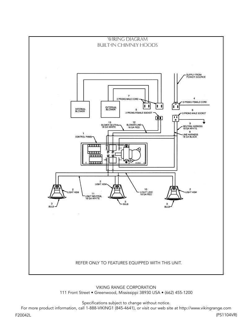
WIRING DIAGRAMBUILT-IN CHIMNEY HOODS
REFER ONLY TO FEATURES EQUIPPED WITH THIS UNIT.
VIKING RANGE CORPORATION111 Front Street • Greenwood, Mississippi 38930 USA • (662) 455-1200
Specifications subject to change without notice.For more product information, call 1-888-VIKING1 (845-4641), or visit our web site at http://www.vikingrange.com
F20042L (PS1104VR)


![Viking Range cooking team [testimonial]](https://img.pdfslide.us/doc/110x75/559427d71a28ab0f418b45b1/viking-range-cooking-team-testimonial.jpg)