Embed Size (px)
Citation preview
1 ENGLISH
Installation & User Guide
V1.1
2
ContentsIntroducing the immerSUN
Main Screen
Savings
Boost (Manual)
Boost (Timed)
Menu
View Readings
Advanced Settings
External Boost Input
Multifunction Relay
Installation
System Overview
immerLINK™ (linking units)
immerSUN at a glance
Electrical Connections
Sensor Installation
Setup
Wiring Diagrams
Wiring: Single Heater
Wiring: Two Heater
Wiring: Three Heater
Wiring: Underfloor Heating (opt. 1)
Wiring: Underfloor Heating (opt. 2)
Wiring: Dual Tariff (Single Meter)
Wiring: Dual Tariff (Dual Meter)
Error Messages
Technical Specification
3
4
5
6
7
8
10
12
13
14
16
18
19
20
22
23
24
25
26
28
30
32
34
36
38
40
42
3
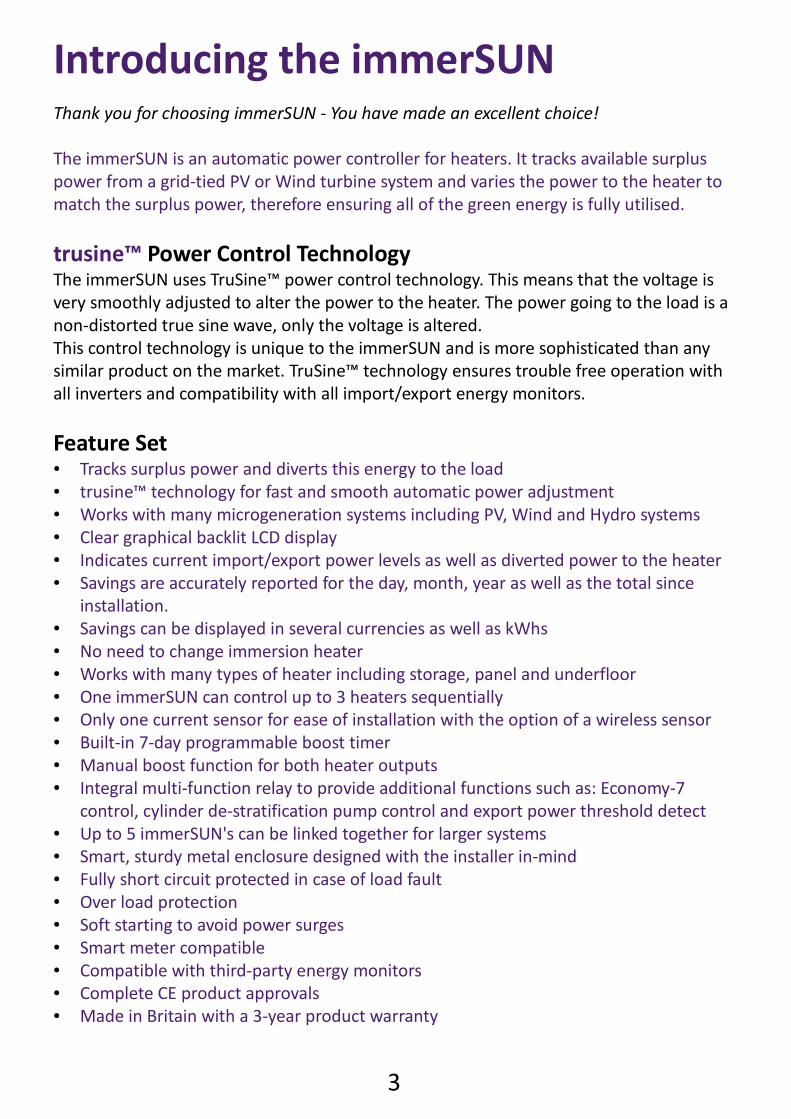
Introducing the immerSUNThank you for choosing immerSUN - You have made an excellent choice!
The immerSUN is an automatic power controller for heaters. It tracks available surplus
power from a grid-tied PV or Wind turbine system and varies the power to the heater to
match the surplus power, therefore ensuring all of the green energy is fully utilised.
trusine™ Power Control Technology
The immerSUN uses TruSine™ power control technology. This means that the voltage is
very smoothly adjusted to alter the power to the heater. The power going to the load is a
non-distorted true sine wave, only the voltage is altered.
This control technology is unique to the immerSUN and is more sophisticated than any
similar product on the market. TruSine™ technology ensures trouble free operation with
all inverters and compatibility with all import/export energy monitors.
Feature Set Tracks surplus power and diverts this energy to the load trusine™ technology for fast and smooth automatic power adjustment Works with many microgeneration systems including PV, Wind and Hydro systems Clear graphical backlit LCD display Indicates current import/export power levels as well as diverted power to the heater Savings are accurately reported for the day, month, year as well as the total since
installation. Savings can be displayed in several currencies as well as kWhs No need to change immersion heater Works with many types of heater including storage, panel and underfloor One immerSUN can control up to 3 heaters sequentially Only one current sensor for ease of installation with the option of a wireless sensor Built-in 7-day programmable boost timer Manual boost function for both heater outputs Integral multi-function relay to provide additional functions such as: Economy-7
control, cylinder de-stratification pump control and export power threshold detect Up to 5 immerSUN's can be linked together for larger systems Smart, sturdy metal enclosure designed with the installer in-mind Fully short circuit protected in case of load fault Over load protection Soft starting to avoid power surges Smart meter compatible Compatible with third-party energy monitors Complete CE product approvals Made in Britain with a 3-year product warranty
4
×
SAVINGS MENU
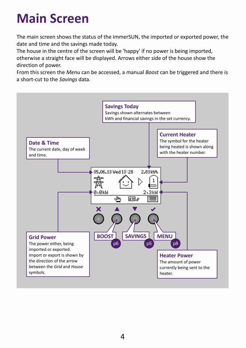
Savings TodaySavings shown alternates between
kWh and financial savings in the set currency.
Current HeaterThe symbol for the heater
being heated is shown along
with the heater number.
Heater PowerThe amount of power
currently being sent to the
heater.
Grid PowerThe power either, being
imported or exported.
Import or export is shown by
the direction of the arrow
between the Grid and House
symbols.
Date & TimeThe current date, day of week
and time.
Main Screen
The main screen shows the status of the immerSUN, the imported or exported power, the
date and time and the savings made today.
The house in the centre of the screen will be 'happy' if no power is being imported,
otherwise a straight face will be displayed. Arrows either side of the house show the
direction of power.
From this screen the Menu can be accessed, a manual Boost can be triggered and there is
a short-cut to the Savings data.
p8p5
BOOST
p6
5
Savings
×
SAVINGS
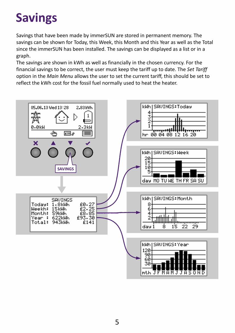
Savings that have been made by immerSUN are stored in permanent memory. The
savings can be shown for Today, this Week, this Month and this Year as well as the Total
since the immerSUN has been installed. The savings can be displayed as a list or in a
graph.
The savings are shown in kWh as well as financially in the chosen currency. For the
financial savings to be correct, the user must keep the tariff up to date. The Set Tariff
option in the Main Menu allows the user to set the current tariff, this should be set to
reflect the kWh cost for the fossil fuel normally used to heat the heater.
6
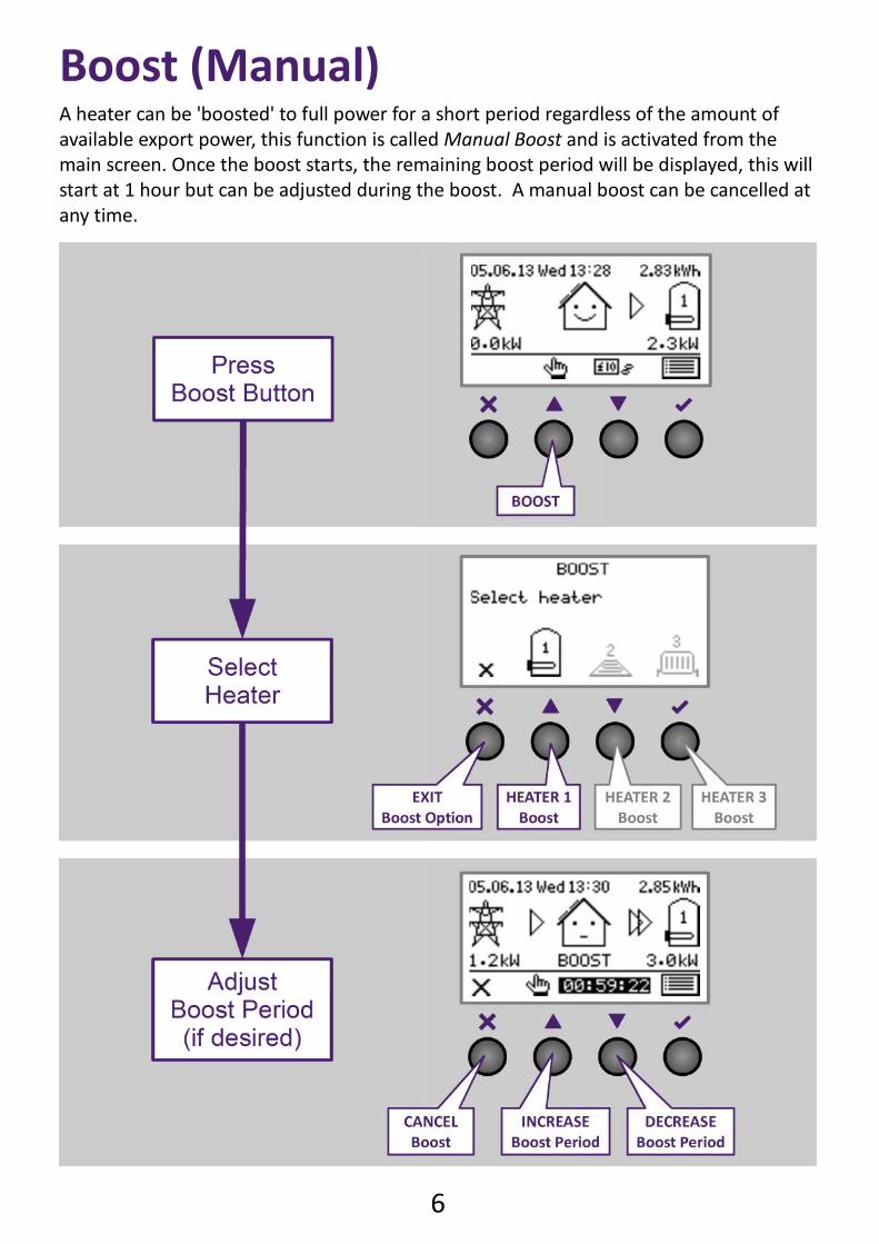
Boost (Manual)A heater can be 'boosted' to full power for a short period regardless of the amount of
available export power, this function is called Manual Boost and is activated from the
main screen. Once the boost starts, the remaining boost period will be displayed, this will
start at 1 hour but can be adjusted during the boost. A manual boost can be cancelled at
any time.
7
Boost (Timed)
Important points
Up to six different boost times can be entered. Each week day can be individually selected for each boost time. Only ONE heater can be boosted at any one time. If any boost times overlap, the latest timed boost will take presidence. For boost times crossing midnight, two time slots will need to be used.
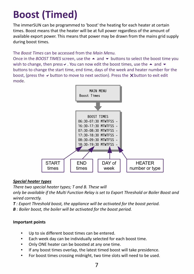
The immerSUN can be programmed to 'boost' the heating for each heater at certain
times. Boost means that the heater will be at full power regardless of the amount of
available export power. This means that power may be drawn from the mains grid supply
during boost times.
The Boost Times can be accessed from the Main Menu.
Once in the BOOST TIMES screen, use the and buttons to select the boost time you
wish to change, then press. You can now edit the boost times, use the and
buttons to change the start time, end time, days of the week and heater number for the
boost, (press the button to move to next section). Press the button to exit edit
mode.
BOOST TIMES
06:30-07:30 MTWTFSS -
16:30-17:30 MTWTFSS -
07:30-08:30 MTWTFSS -
17:30-18:30 MTWTFSS -
08:30-09:30 MTWTFSS -
18:30-19:30 MTWTFSS -
BOOST TIMES
06:30-07:30 MTWTFSS -
16:30-17:30 MTWTFSS -
07:30-08:30 MTWTFSS -
17:30-18:30 MTWTFSS -
08:30-09:30 MTWTFSS -
18:30-19:30 MTWTFSS -
STARTtimes
ENDtimes
DAY ofweek
HEATERnumber or type
MAIN MENU
Boost Times
MAIN MENU
Boost Times
Special heater types
There two special heater types; T and B. These will
only be available if the Multi Function Relay is set to Export Threshold or Boiler Boost and
wired correctly.
T : Export Threshold boost, the appliance will be activated for the boost period.
B : Boiler boost, the boiler will be activated for the boost period.
8
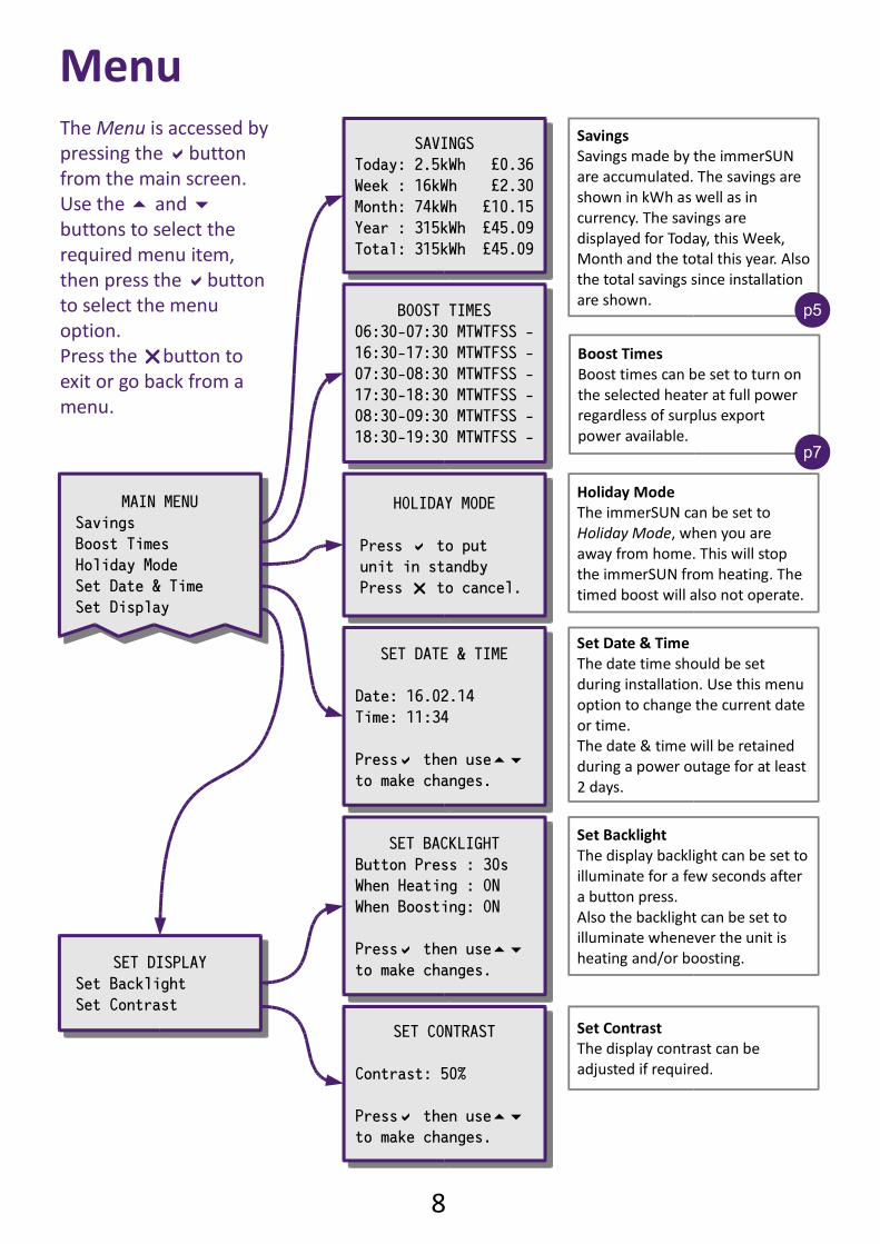
Holiday Mode
The immerSUN can be set to
Holiday Mode, when you are
away from home. This will stop
the immerSUN from heating. The
timed boost will also not operate.
Set Date & Time
The date time should be set
during installation. Use this menu
option to change the current date
or time.
The date & time will be retained
during a power outage for at least
2 days.
Set Backlight
The display backlight can be set to
illuminate for a few seconds after
a button press.
Also the backlight can be set to
illuminate whenever the unit is
heating and/or boosting.
Set Contrast
The display contrast can be
adjusted if required.
Savings
Savings made by the immerSUN
are accumulated. The savings are
shown in kWh as well as in
currency. The savings are
displayed for Today, this Week,
Month and the total this year. Also
the total savings since installation
are shown.
Boost Times
Boost times can be set to turn on
the selected heater at full power
regardless of surplus export
power available.
Menu
MAIN MENU
Savings
Boost Times
Holiday Mode
Set Date & Time
Set Display
MAIN MENU
Savings
Boost Times
Holiday Mode
Set Date & Time
Set Display
SAVINGS
Today: 2.5kWh £0.36
Week : 16kWh £2.30
Month: 74kWh £10.15
Year : 315kWh £45.09
Total: 315kWh £45.09
SAVINGS
Today: 2.5kWh £0.36
Week : 16kWh £2.30
Month: 74kWh £10.15
Year : 315kWh £45.09
Total: 315kWh £45.09
BOOST TIMES
06:30-07:30 MTWTFSS -
16:30-17:30 MTWTFSS -
07:30-08:30 MTWTFSS -
17:30-18:30 MTWTFSS -
08:30-09:30 MTWTFSS -
18:30-19:30 MTWTFSS -
BOOST TIMES
06:30-07:30 MTWTFSS -
16:30-17:30 MTWTFSS -
07:30-08:30 MTWTFSS -
17:30-18:30 MTWTFSS -
08:30-09:30 MTWTFSS -
18:30-19:30 MTWTFSS -
HOLIDAY MODE
Press to put
unit in standby
Press to cancel.
HOLIDAY MODE
Press to put
unit in standby
Press to cancel.
SET DATE & TIME
Date: 16.02.14
Time: 11:34
Press then use
to make changes.
SET DATE & TIME
Date: 16.02.14
Time: 11:34
Press then use
to make changes.
SET DISPLAY
Set Backlight
Set Contrast
SET DISPLAY
Set Backlight
Set Contrast
SET BACKLIGHT
Button Press : 30s
When Heating : ON
When Boosting: ON
Press then use
to make changes.
SET BACKLIGHT
Button Press : 30s
When Heating : ON
When Boosting: ON
Press then use
to make changes.
SET CONTRAST
Contrast: 50%
Press then use
to make changes.
SET CONTRAST
Contrast: 50%
Press then use
to make changes.
p7
p5
The Menu is accessed by
pressing the button
from the main screen.
Use the and
buttons to select the
required menu item,
then press the button
to select the menu
option.
Press the button to
exit or go back from a
menu.
9
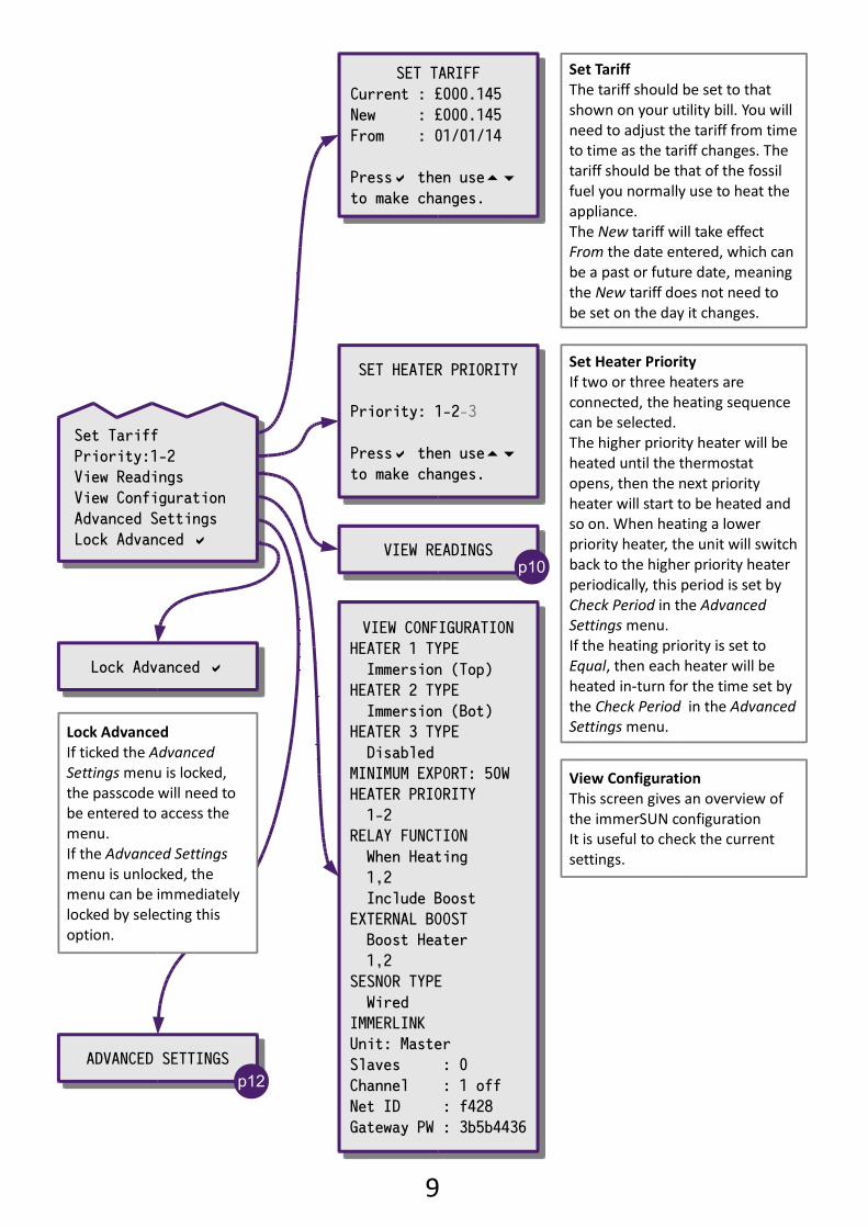
Set Tariff
Priority:1-2
View Readings
View Configuration
Advanced Settings
Lock Advanced
Set Tariff
Priority:1-2
View Readings
View Configuration
Advanced Settings
Lock Advanced
Set Tariff
The tariff should be set to that
shown on your utility bill. You will
need to adjust the tariff from time
to time as the tariff changes. The
tariff should be that of the fossil
fuel you normally use to heat the
appliance.
The New tariff will take effect
From the date entered, which can
be a past or future date, meaning
the New tariff does not need to
be set on the day it changes.
Set Heater Priority
If two or three heaters are
connected, the heating sequence
can be selected.
The higher priority heater will be
heated until the thermostat
opens, then the next priority
heater will start to be heated and
so on. When heating a lower
priority heater, the unit will switch
back to the higher priority heater
periodically, this period is set by
Check Period in the Advanced
Settings menu.
If the heating priority is set to
Equal, then each heater will be
heated in-turn for the time set by
the Check Period in the Advanced
Settings menu.
View Configuration
This screen gives an overview of
the immerSUN configuration
It is useful to check the current
settings.
SET TARIFF
Current : £000.145
New : £000.145
From : 01/01/14
Press then use
to make changes.
SET TARIFF
Current : £000.145
New : £000.145
From : 01/01/14
Press then use
to make changes.
VIEW READINGSVIEW READINGS
ADVANCED SETTINGSADVANCED SETTINGS
p12
SET HEATER PRIORITY
Priority: 1-2-3
Press then use
to make changes.
SET HEATER PRIORITY
Priority: 1-2-3
Press then use
to make changes.
p10
VIEW CONFIGURATION
HEATER 1 TYPE
Immersion (Top)
HEATER 2 TYPE
Immersion (Bot)
HEATER 3 TYPE
Disabled
MINIMUM EXPORT: 50W
HEATER PRIORITY
1-2
RELAY FUNCTION
When Heating
1,2
Include Boost
EXTERNAL BOOST
Boost Heater
1,2
SESNOR TYPE
Wired
IMMERLINK
Unit: Master
Slaves : 0
Channel : 1 off
Net ID : f428
Gateway PW : 3b5b4436
Lock Advanced Lock Advanced
Lock Advanced
If ticked the Advanced
Settings menu is locked,
the passcode will need to
be entered to access the
menu.
If the Advanced Settings
menu is unlocked, the
menu can be immediately
locked by selecting this
option.
10
MAIN MENU
View Readings
MAIN MENU
View Readings
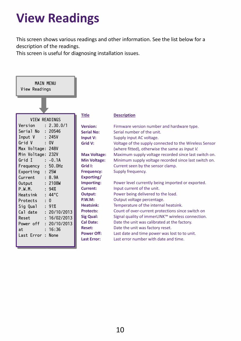
View Readings
This screen shows various readings and other information. See the list below for a
description of the readings.
This screen is useful for diagnosing installation issues.
Title Description
Version: Firmware version number and hardware type.
Serial No: Serial number of the unit.
Input V: Supply input AC voltage.
Grid V: Voltage of the supply connected to the Wireless Sensor
(where fitted), otherwise the same as Input V.
Max Voltage: Maximum supply voltage recorded since last switch on.
Min Voltage: Minimum supply voltage recorded since last switch on.
Grid I: Current seen by the sensor clamp.
Frequency: Supply frequency.
Exporting/
Importing: Power level currently being imported or exported.
Current: Input current of the unit.
Output: Power being delivered to the load.
P.W.M: Output voltage percentage.
Heatsink: Temperature of the internal heatsink.
Protects: Count of over-current protections since switch on
Sig Qual: Signal quality of immerLINK™ wireless connection.
Cal Date: Date the unit was calibrated at the factory.
Reset: Date the unit was factory reset.
Power Off: Last date and time power was lost to to unit.
Last Error: Last error number with date and time.
VIEW READINGS
Version : 2.30.0/1
Serial No : 20546
Input V : 245V
Grid V : 0V
Max Voltage: 248V
Min Voltage: 232V
Grid I : -0.1A
Frequency : 50.0Hz
Exporting : 25W
Current : 8.9A
Output : 2108W
P.W.M. : 94%
Heatsink : 44°C
Protects : 0
Sig Qual : 91%
Cal date : 20/10/2013
Reset : 16/02/2013
Power off : 20/10/2013
at : 16:36
Last Error : None

11
Advanced options...
12
ADVANCED SETTINGS
Heater 1 Type
Heater 2 Type
Heater 3 Type
Minimum Export
Check Period
Relay Function
External Boost
Immerlink
Set Passcode
Locked Functions
Daylight Savings Time
Factory Reset
ADVANCED SETTINGS
Heater 1 Type
Heater 2 Type
Heater 3 Type
Minimum Export
Check Period
Relay Function
External Boost
Immerlink
Set Passcode
Locked Functions
Daylight Savings Time
Factory Reset
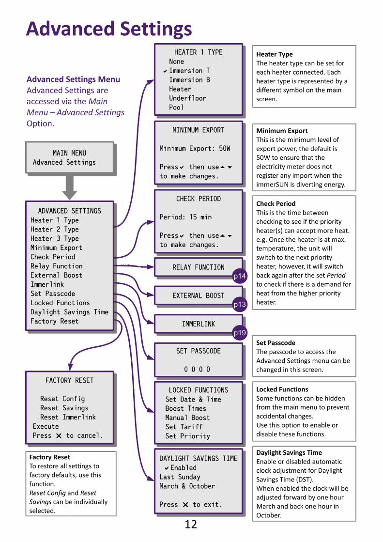
Heater Type
The heater type can be set for
each heater connected. Each
heater type is represented by a
different symbol on the main
screen.
Check Period
This is the time between
checking to see if the priority
heater(s) can accept more heat.
e.g. Once the heater is at max.
temperature, the unit will
switch to the next priority
heater, however, it will switch
back again after the set Period
to check if there is a demand for
heat from the higher priority
heater.
Advanced Settings
Advanced Settings Menu
Advanced Settings are
accessed via the Main
Menu – Advanced Settings
Option.
HEATER 1 TYPE
None
Immersion T
Immersion B
Heater
Underfloor
Pool
HEATER 1 TYPE
None
Immersion T
Immersion B
Heater
Underfloor
Pool
CHECK PERIOD
Period: 15 min
Press then use
to make changes.
CHECK PERIOD
Period: 15 min
Press then use
to make changes.
RELAY FUNCTIONRELAY FUNCTIONp14
EXTERNAL BOOSTEXTERNAL BOOST
p13
MAIN MENU
Advanced Settings
MAIN MENU
Advanced Settings
IMMERLINKIMMERLINK
FACTORY RESET
Reset Config
Reset Savings
Reset Immerlink
Execute
Press to cancel.
FACTORY RESET
Reset Config
Reset Savings
Reset Immerlink
Execute
Press to cancel.
Factory Reset
To restore all settings to
factory defaults, use this
function.
Reset Config and Reset
Savings can be individually
selected.
p19
MINIMUM EXPORT
Minimum Export: 50W
Press then use
to make changes.
MINIMUM EXPORT
Minimum Export: 50W
Press then use
to make changes.
Minimum Export
This is the minimum level of
export power, the default is
50W to ensure that the
electricity meter does not
register any import when the
immerSUN is diverting energy.
SET PASSCODE
0 0 0 0
SET PASSCODE
0 0 0 0
Set Passcode
The passcode to access the
Advanced Settings menu can be
changed in this screen.
LOCKED FUNCTIONS
Set Date & Time
Boost Times
Manual Boost
Set Tariff
Set Priority
LOCKED FUNCTIONS
Set Date & Time
Boost Times
Manual Boost
Set Tariff
Set Priority
DAYLIGHT SAVINGS TIME
Enabled
Last Sunday
March & October
Press to exit.
DAYLIGHT SAVINGS TIME
Enabled
Last Sunday
March & October
Press to exit.
Locked Functions
Some functions can be hidden
from the main menu to prevent
accidental changes.
Use this option to enable or
disable these functions.
Daylight Savings Time
Enable or disabled automatic
clock adjustment for Daylight
Savings Time (DST).
When enabled the clock will be
adjusted forward by one hour
March and back one hour in
October.
13
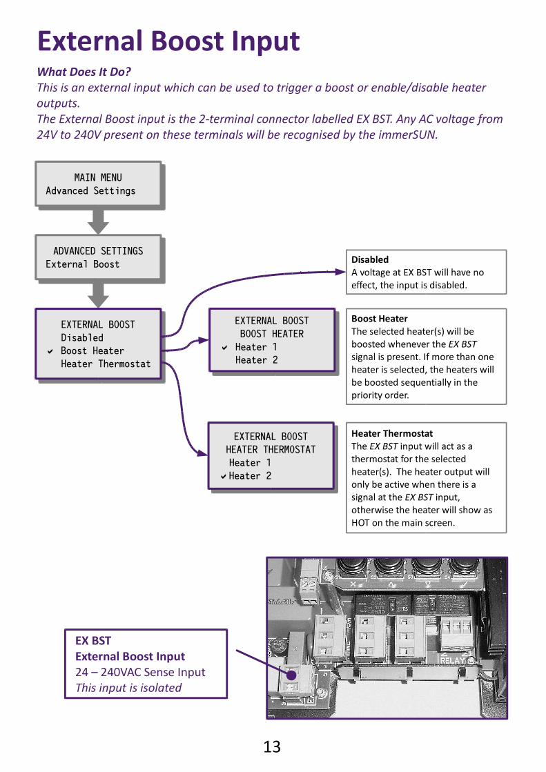
What Does It Do?
This is an external input which can be used to trigger a boost or enable/disable heater
outputs.
The External Boost input is the 2-terminal connector labelled EX BST. Any AC voltage from
24V to 240V present on these terminals will be recognised by the immerSUN.
EXTERNAL BOOST
Disabled
Boost Heater
Heater Thermostat
EXTERNAL BOOST
Disabled
Boost Heater
Heater Thermostat
Boost Heater
The selected heater(s) will be
boosted whenever the EX BST
signal is present. If more than one
heater is selected, the heaters will
be boosted sequentially in the
priority order.
Heater Thermostat
The EX BST input will act as a
thermostat for the selected
heater(s). The heater output will
only be active when there is a
signal at the EX BST input,
otherwise the heater will show as
HOT on the main screen.
External Boost Input
EX BST
External Boost Input
24 – 240VAC Sense Input
This input is isolated
EXTERNAL BOOST
HEATER THERMOSTAT
Heater 1
Heater 2
EXTERNAL BOOST
HEATER THERMOSTAT
Heater 1
Heater 2
ADVANCED SETTINGS
External Boost
ADVANCED SETTINGS
External Boost
MAIN MENU
Advanced Settings
MAIN MENU
Advanced Settings
Disabled
A voltage at EX BST will have no
effect, the input is disabled.
EXTERNAL BOOST
BOOST HEATER
Heater 1
Heater 2
EXTERNAL BOOST
BOOST HEATER
Heater 1
Heater 2
14
ADVANCED SETTINGS
Relay Function
ADVANCED SETTINGS
Relay Function
MAIN MENU
Advanced Settings
MAIN MENU
Advanced Settings
RELAY FUNCTION
Disabled
Always On
When Heating
When Boosting
Boiler Boost
Destrat Pump
RELAY FUNCTION
Disabled
Always On
When Heating
When Boosting
Boiler Boost
Destrat Pump
RELAY:WHEN HEATING
Heater 1
Heater 2
Include Hot
Include Boost
RELAY:WHEN HEATING
Heater 1
Heater 2
Include Hot
Include Boost
RELAY:WHEN BOOSTING
Heater 1
Heater 2
RELAY:WHEN BOOSTING
Heater 1
Heater 2
RELAY:DESTRAT PUMP
Heater 1
Heater 2
RELAY:DESTRAT PUMP
Heater 1
Heater 2
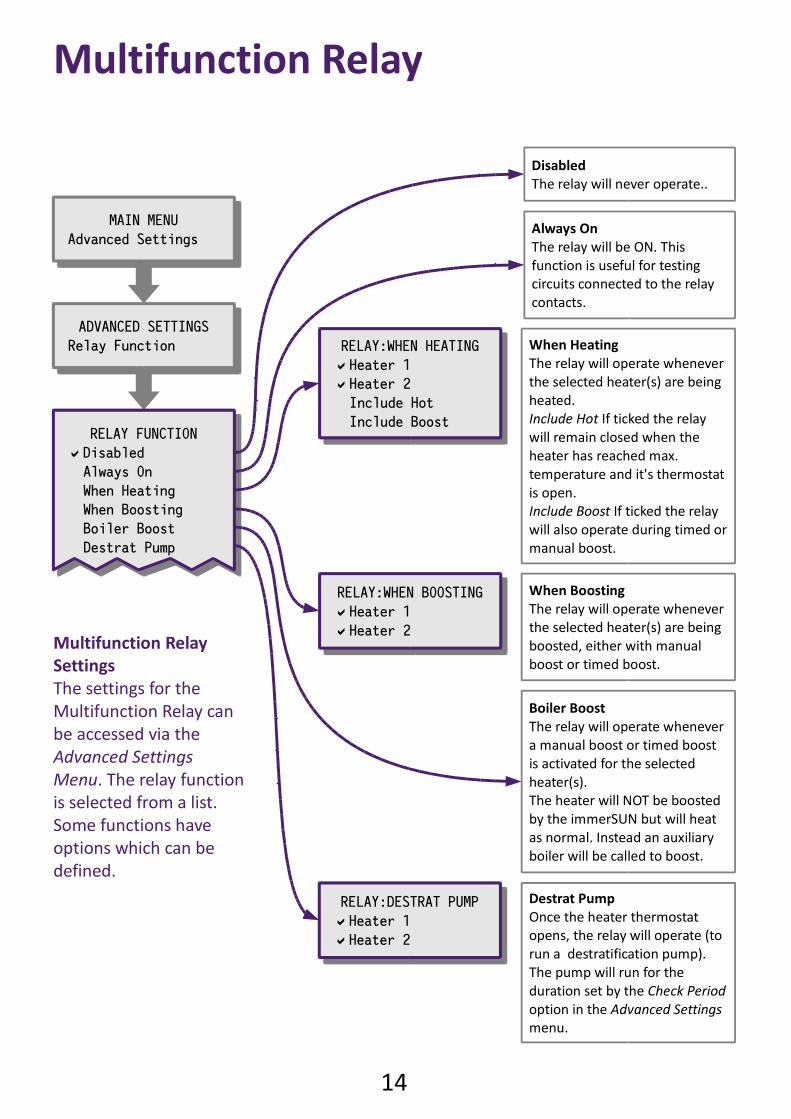
When Heating
The relay will operate whenever
the selected heater(s) are being
heated.
Include Hot If ticked the relay
will remain closed when the
heater has reached max.
temperature and it's thermostat
is open.
Include Boost If ticked the relay
will also operate during timed or
manual boost.
When Boosting
The relay will operate whenever
the selected heater(s) are being
boosted, either with manual
boost or timed boost.
Boiler Boost
The relay will operate whenever
a manual boost or timed boost
is activated for the selected
heater(s).
The heater will NOT be boosted
by the immerSUN but will heat
as normal. Instead an auxiliary
boiler will be called to boost.
Destrat Pump
Once the heater thermostat
opens, the relay will operate (to
run a destratification pump).
The pump will run for the
duration set by the Check Period
option in the Advanced Settings
menu.
Disabled
The relay will never operate..
Always On
The relay will be ON. This
function is useful for testing
circuits connected to the relay
contacts.
Multifunction Relay
Multifunction Relay
Settings
The settings for the
Multifunction Relay can
be accessed via the
Advanced Settings
Menu. The relay function
is selected from a list.
Some functions have
options which can be
defined.
15
Third Heater
When External Boost
Export Threshold
Fault Signal
Third Heater
When External Boost
Export Threshold
Fault Signal
RELAY:EXP. THRESHOLD
Threshold: 500W
ON Period: 15min
OFF Period: 0min
Priority: High
RELAY:EXP. THRESHOLD
Threshold: 500W
ON Period: 15min
OFF Period: 0min
Priority: High
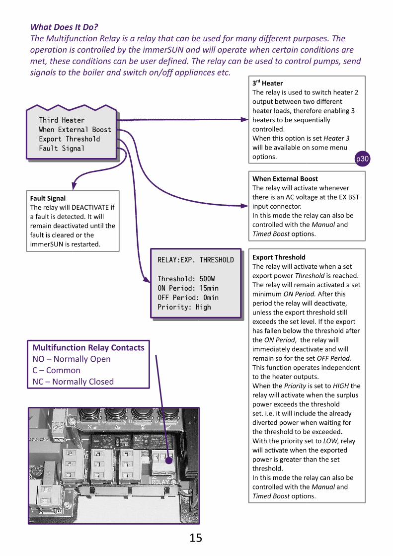
Fault Signal
The relay will DEACTIVATE if
a fault is detected. It will
remain deactivated until the
fault is cleared or the
immerSUN is restarted.
When External Boost
The relay will activate whenever
there is an AC voltage at the EX BST
input connector.
In this mode the relay can also be
controlled with the Manual and
Timed Boost options.
Export Threshold
The relay will activate when a set
export power Threshold is reached.
The relay will remain activated a set
minimum ON Period. After this
period the relay will deactivate,
unless the export threshold still
exceeds the set level. If the export
has fallen below the threshold after
the ON Period, the relay will
immediately deactivate and will
remain so for the set OFF Period.
This function operates independent
to the heater outputs.
When the Priority is set to HIGH the
relay will activate when the surplus
power exceeds the threshold
set. i.e. it will include the already
diverted power when waiting for
the threshold to be exceeded.
With the priority set to LOW, relay
will activate when the exported
power is greater than the set
threshold.
In this mode the relay can also be
controlled with the Manual and
Timed Boost options.
What Does It Do?
The Multifunction Relay is a relay that can be used for many different purposes. The
operation is controlled by the immerSUN and will operate when certain conditions are
met, these conditions can be user defined. The relay can be used to control pumps, send
signals to the boiler and switch on/off appliances etc.
Multifunction Relay Contacts
NO – Normally Open
C – Common
NC – Normally Closed
3rd Heater
The relay is used to switch heater 2
output between two different
heater loads, therefore enabling 3
heaters to be sequentially
controlled.
When this option is set Heater 3
will be available on some menu
options. p30
16
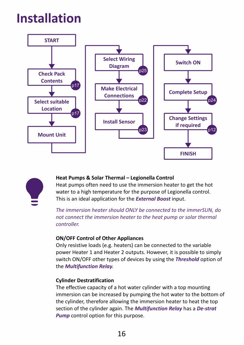
Installation
Heat Pumps & Solar Thermal – Legionella Control
Heat pumps often need to use the immersion heater to get the hot
water to a high temperature for the purpose of Legionella control.
This is an ideal application for the External Boost input.
The immersion heater should ONLY be connected to the immerSUN, do
not connect the immersion heater to the heat pump or solar thermal
controller.
ON/OFF Control of Other Appliances
Only resistive loads (e.g. heaters) can be connected to the variable
power Heater 1 and Heater 2 outputs. However, it is possible to simply
switch ON/OFF other types of devices by using the Threshold option of
the Multifunction Relay.
Cylinder Destratification
The effective capacity of a hot water cylinder with a top mounting
immersion can be increased by pumping the hot water to the bottom of
the cylinder, therefore allowing the immersion heater to heat the top
section of the cylinder again. The Multifunction Relay has a De-strat
Pump control option for this purpose.
Check Pack
Contents
Select suitable
Location
Mount Unit
Install Sensor
Switch ON
Complete Setup
Change Settings
if required
Make Electrical
Connections
Select Wiring
Diagram
START
FINISH
p17
p17
p25
p22
p23
p24
p12
17
What's in the Pack
immerSUN
Sensor Clamp
Fixing Kit
Antenna
Locating the immerSUNOften, the most suitable location for the immerSUN is near to the distribution board as
all the connections required are usually available here.
Alternatively the unit can be mounted next to the load. Note that the Sensor clamp must
be clamped around the supply meter-tail. There is the option of using the Wireless
Sensor to simplify the installation if required.
The following should be considered when deciding upon the most suitable location:
Close to the main incoming mains electrical supply of the property – otherwise
the Sensor Clamp will need to be extended, or the Wireless Sensor option used. Access to heater supply cable (this is usually at the consumer unit) Access to suitable supply via 16A MCB or 13A fused outlet User access to the buttons and visibility of LCD screen Adequate ventilation – keep vents clear and provide airflow around the unit.
Mimi mum clearance top and bottom is 50mm although more is recommend for
ease of access to case screws. Cable access point – through the top, bottom or rear of the unit - the bottom
panel is removable to give better access when wiring.
Voltage OptimisersIf there is a voltage optimiser installed at the property, care will need to be taken when
positioning and wiring the immerSUN. The Sensor Clamp and the immerSUN will need to
'see' the same voltage, whether this is the optimised voltage or the non-optimised
voltage.
Check the manufacturers instructions before connecting the immerSUN to an optimised
circuit – some optimisers should not be connected to heaters.
Three-Phase SystemsThe immerSUN and the Sensor Clamp must be on the SAME PHASE.
If the generation is 3-phase, an immerSUN can be used on each phase, if only one or two
immerSUN's are used, only one-third or two-thirds of the surplus power will be able to be
utilised. The loads will need to be single phase.
18
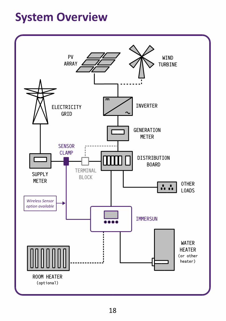
System Overview
INVERTER
WIND
TURBINE
PV
ARRAY
DISTRIBUTION
BOARD
ELECTRICITY
GRID
IMMERSUN
OTHER
LOADS
SENSOR
CLAMP
WATER
HEATER(or other
heater)
GENERATION
METER
TERMINAL
BLOCK
ROOM HEATER(optional)
Wireless Sensor
option available
SUPPLY
METER
19
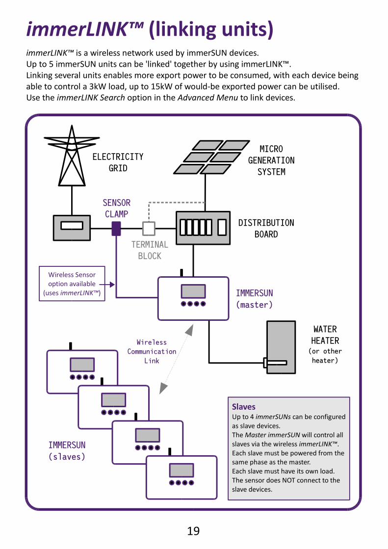
immerLINK™ (linking units)
MICRO
GENERATION
SYSTEM
DISTRIBUTION
BOARD
ELECTRICITY
GRID
IMMERSUN
(master)
SENSOR
CLAMP
WATER
HEATER(or other
heater)
TERMINAL
BLOCK
Wireless Sensor
option available
(uses immerLINK™)
Wireless
Communication
Link
IMMERSUN
(slaves)
SlavesUp to 4 immerSUNs can be configured
as slave devices.
The Master immerSUN will control all
slaves via the wireless immerLINK™.
Each slave must be powered from the
same phase as the master.
Each slave must have its own load.
The sensor does NOT connect to the
slave devices.
immerLINK™ is a wireless network used by immerSUN devices.
Up to 5 immerSUN units can be 'linked' together by using immerLINK™.
Linking several units enables more export power to be consumed, with each device being
able to control a 3kW load, up to 15kW of would-be exported power can be utilised.
Use the immerLINK Search option in the Advanced Menu to link devices.
20
immerSUN at a glance
646
312 4
5
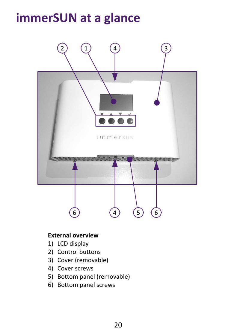
External overview
1) LCD display
2) Control buttons
3) Cover (removable)
4) Cover screws
5) Bottom panel (removable)
6) Bottom panel screws
21
647 3
1
2 5
8 8
9
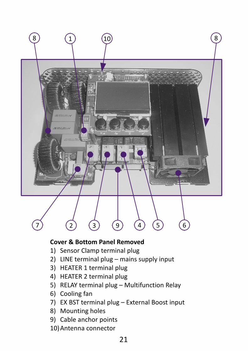
Cover & Bottom Panel Removed
1) Sensor Clamp terminal plug
2) LINE terminal plug – mains supply input
3) HEATER 1 terminal plug
4) HEATER 2 terminal plug
5) RELAY terminal plug – Multifunction Relay
6) Cooling fan
7) EX BST terminal plug – External Boost input
8) Mounting holes
9) Cable anchor points
10)Antenna connector
10
22
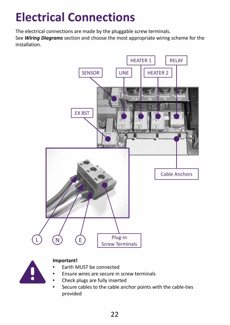
Electrical ConnectionsThe electrical connections are made by the pluggable screw terminals.
See Wiring Diagrams section and choose the most appropriate wiring scheme for the
installation.
Important! Earth MUST be connected Ensure wires are secure in screw terminals Check plugs are fully inserted Secure cables to the cable anchor points with the cable-ties
provided
ENL Plug-in
Screw Terminals
Cable Anchors
LINE HEATER 2
HEATER 1 RELAY
EX BST
SENSOR
23
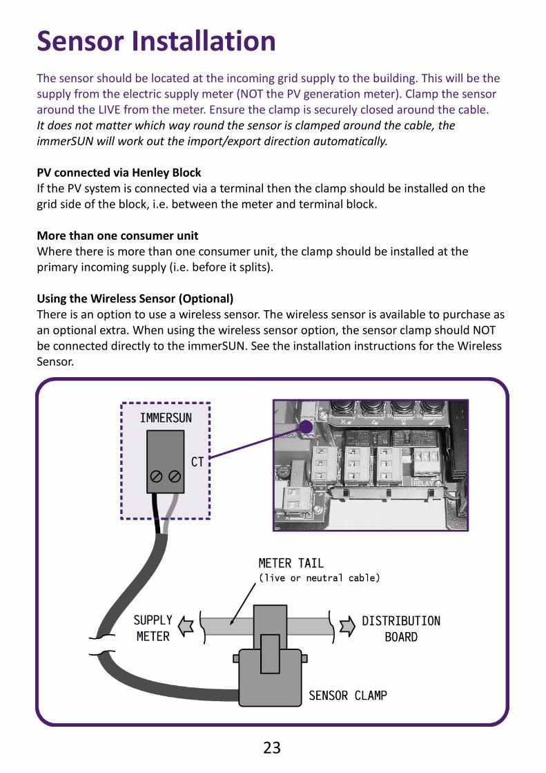
Sensor InstallationThe sensor should be located at the incoming grid supply to the building. This will be the
supply from the electric supply meter (NOT the PV generation meter). Clamp the sensor
around the LIVE from the meter. Ensure the clamp is securely closed around the cable.
It does not matter which way round the sensor is clamped around the cable, the
immerSUN will work out the import/export direction automatically.
PV connected via Henley Block
If the PV system is connected via a terminal then the clamp should be installed on the
grid side of the block, i.e. between the meter and terminal block.
More than one consumer unit
Where there is more than one consumer unit, the clamp should be installed at the
primary incoming supply (i.e. before it splits).
Using the Wireless Sensor (Optional)
There is an option to use a wireless sensor. The wireless sensor is available to purchase as
an optional extra. When using the wireless sensor option, the sensor clamp should NOT
be connected directly to the immerSUN. See the installation instructions for the Wireless
Sensor.
Setup
25
Wiring diagrams...
26
L
E
N
HEATER 2
L
E
N
LINE
IMMERSUN
L
E
N
HEATER 1
EX BST
NO
NC C
RELAY
HEATER &
THERMOSTAT
LOAD
ISOLATOR
3.2KW max.
SUPPLY
ISOLATOR
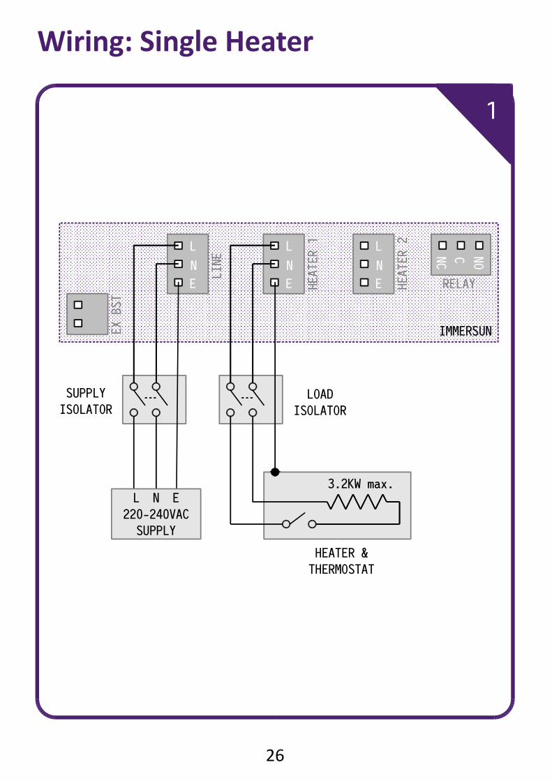
Wiring: Single Heater
1
L N E
220-240VAC
SUPPLY
27
Single Heater Wiring
This is most simple installation and the most common.
One heater is wired to the Heater 1 output.
The heater is heated with surplus power until the thermostat opens, the
immerSUN will then display HOT. The surplus power will then be
exported until the thermostat closes and heating will resume.
Isolators
The isolators shown may not be required but there should always be a
way of isolating the supply, e.g. the MCB can be used for isolation, if the
immerSUN is located next to the consumer unit. Likewise, the load
isolator can be eliminated if the immerSUN and the supply isolation
switch are located near the heater.
Important! Maximum load: 3.2KW Minimum load: 150W Recommended cable size: 2.5mm² Must be a simple resistive load without electronic controls
Settings
Heater 1 Type: Set to match the load
Heater 2 Type: None
Heater 3 Type: None
Relay Function: Not used
External Boost: Not used
Tips & Ideas Smaller loads can be connected in parallel as long the maximum
load is not exceeded. The immerSUN has built-in timers that can replace any timers that
have been removed. The Multifunction Relay is free to use to control other devices. The External Boost input is free to use if an auxiliary device needs to
have some control over the immerSUN.
28
L
E
N
HEATER 2
L
E
N
LINE
IMMERSUN
L
E
N
HEATER 1
EX BST
NO
NC C
RELAY
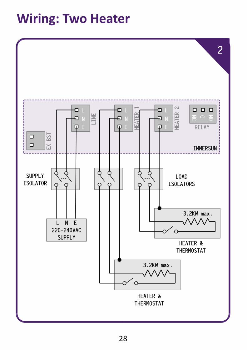
Wiring: Two Heater
2
HEATER &
THERMOSTAT
3.2KW max.
SUPPLY
ISOLATOR
L N E
220-240VAC
SUPPLY
LOAD
ISOLATORS
3.2KW max.
HEATER &
THERMOSTAT
29
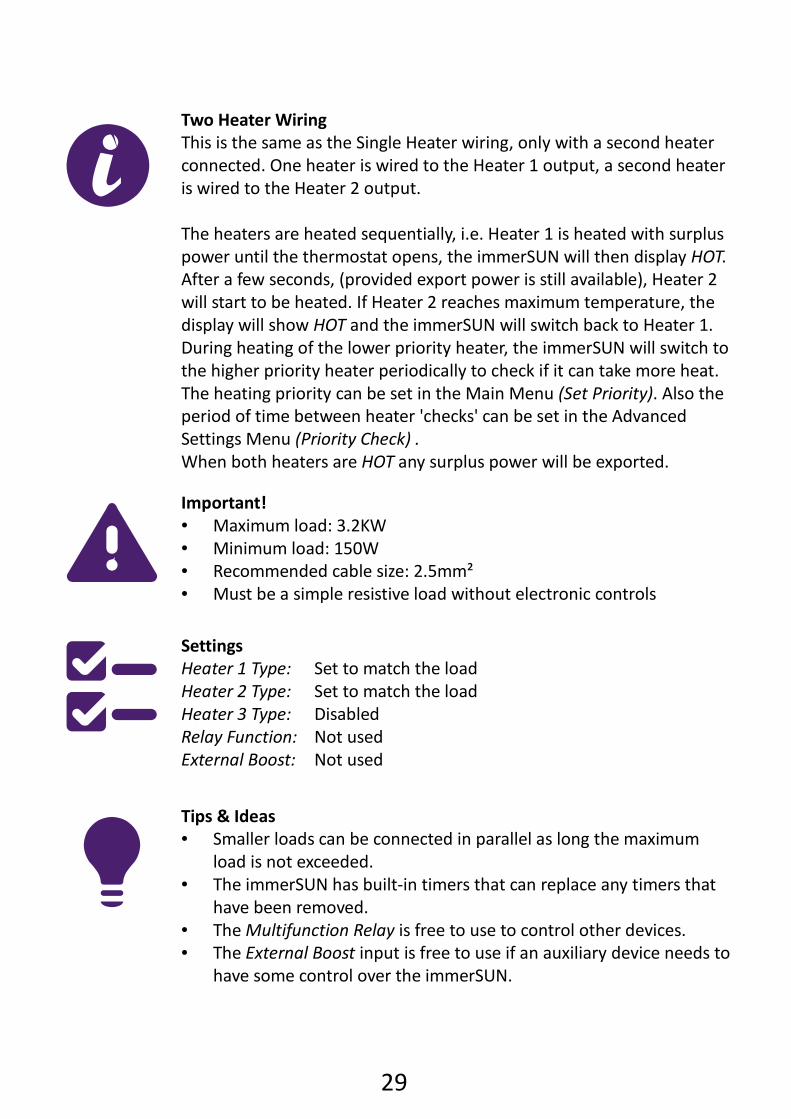
Two Heater Wiring
This is the same as the Single Heater wiring, only with a second heater
connected. One heater is wired to the Heater 1 output, a second heater
is wired to the Heater 2 output.
The heaters are heated sequentially, i.e. Heater 1 is heated with surplus
power until the thermostat opens, the immerSUN will then display HOT.
After a few seconds, (provided export power is still available), Heater 2
will start to be heated. If Heater 2 reaches maximum temperature, the
display will show HOT and the immerSUN will switch back to Heater 1.
During heating of the lower priority heater, the immerSUN will switch to
the higher priority heater periodically to check if it can take more heat.
The heating priority can be set in the Main Menu (Set Priority). Also the
period of time between heater 'checks' can be set in the Advanced
Settings Menu (Priority Check) .
When both heaters are HOT any surplus power will be exported.
Important! Maximum load: 3.2KW Minimum load: 150W Recommended cable size: 2.5mm² Must be a simple resistive load without electronic controls
Settings
Heater 1 Type: Set to match the load
Heater 2 Type: Set to match the load
Heater 3 Type: Disabled
Relay Function: Not used
External Boost: Not used
Tips & Ideas Smaller loads can be connected in parallel as long the maximum
load is not exceeded. The immerSUN has built-in timers that can replace any timers that
have been removed. The Multifunction Relay is free to use to control other devices. The External Boost input is free to use if an auxiliary device needs to
have some control over the immerSUN.
30
Wiring: Three Heater
3
L
E
N
HEATER 2
L
E
N
LINE
IMMERSUN
L
E
N
HEATER 1
3.2KW max.
SUPPLY
ISOLATOR
L N E
220-240VAC
SUPPLY
EX BST
NO
NC C
RELAY
LOAD
ISOLATORS
3.2KW max.
HEATER &
THERMOSTAT
HEATER &
THERMOSTAT
LOAD
ISOLATOR
3.2KW max.
HEATER &
THERMOSTAT
31
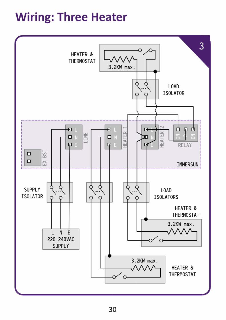
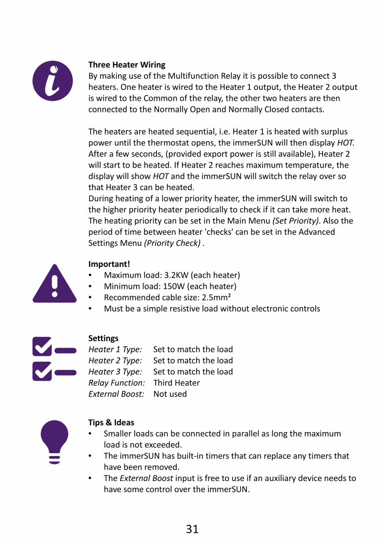
Three Heater Wiring
By making use of the Multifunction Relay it is possible to connect 3
heaters. One heater is wired to the Heater 1 output, the Heater 2 output
is wired to the Common of the relay, the other two heaters are then
connected to the Normally Open and Normally Closed contacts.
The heaters are heated sequential, i.e. Heater 1 is heated with surplus
power until the thermostat opens, the immerSUN will then display HOT.
After a few seconds, (provided export power is still available), Heater 2
will start to be heated. If Heater 2 reaches maximum temperature, the
display will show HOT and the immerSUN will switch the relay over so
that Heater 3 can be heated.
During heating of a lower priority heater, the immerSUN will switch to
the higher priority heater periodically to check if it can take more heat.
The heating priority can be set in the Main Menu (Set Priority). Also the
period of time between heater 'checks' can be set in the Advanced
Settings Menu (Priority Check) .
Important! Maximum load: 3.2KW (each heater) Minimum load: 150W (each heater) Recommended cable size: 2.5mm² Must be a simple resistive load without electronic controls
Settings
Heater 1 Type: Set to match the load
Heater 2 Type: Set to match the load
Heater 3 Type: Set to match the load
Relay Function: Third Heater
External Boost: Not used
Tips & Ideas Smaller loads can be connected in parallel as long the maximum
load is not exceeded. The immerSUN has built-in timers that can replace any timers that
have been removed. The External Boost input is free to use if an auxiliary device needs to
have some control over the immerSUN.
32
L
E
NHEATER 2
L
E
N
LINE
IMMERSUN
L
E
N
HEATER 1
EX BST
NO
NC C
RELAY
Wiring: Underfloor Heating (opt. 1)
4
LOAD
ISOLATOR
SUPPLY
ISOLATOR
3.2KW max.
UFH MAT
L N E
220-240VAC
SUPPLY
L N E
UFH
THERMOSTAT
SUPPLY
ISOLATOR
HEATING DEVICE
& THERMOSTAT
L N E
L N E
3.2KW max.L N E
220-240VAC
SUPPLY
33
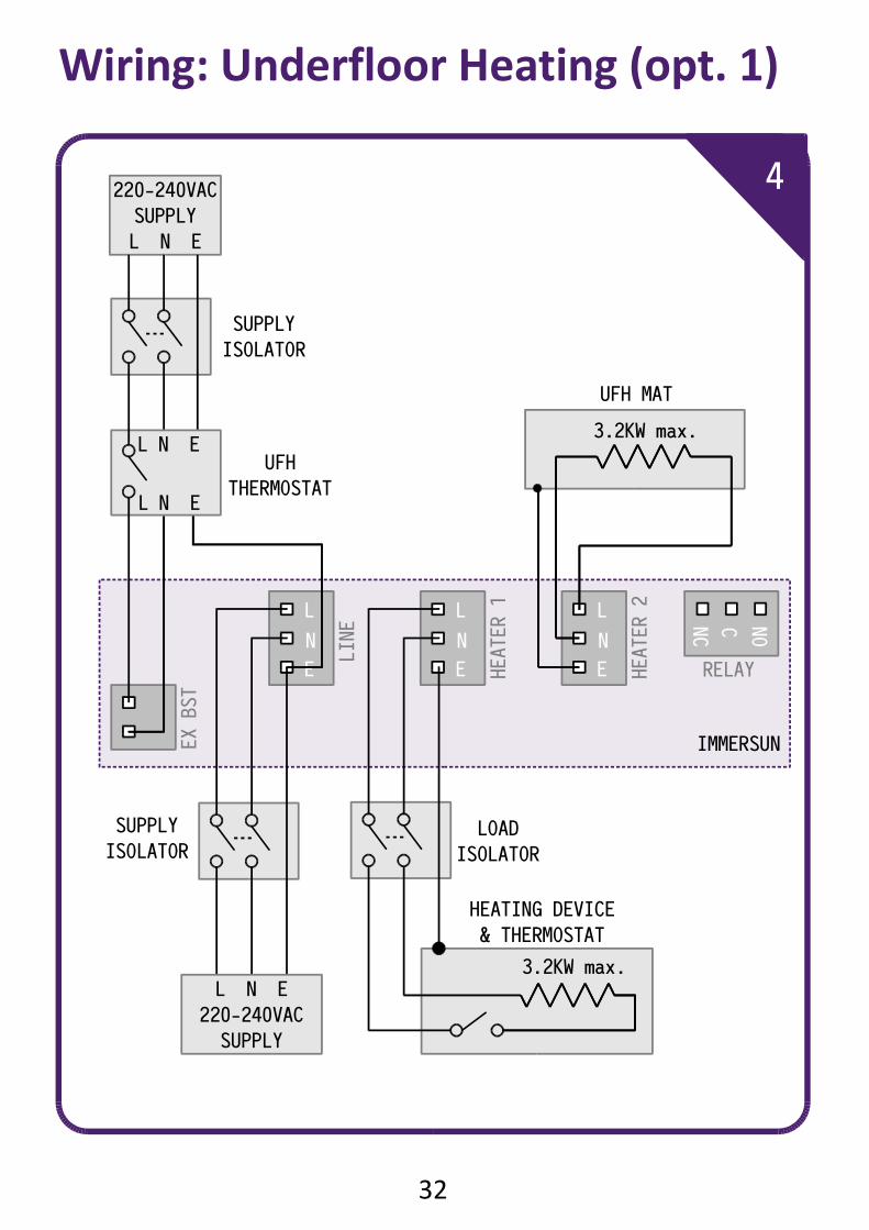
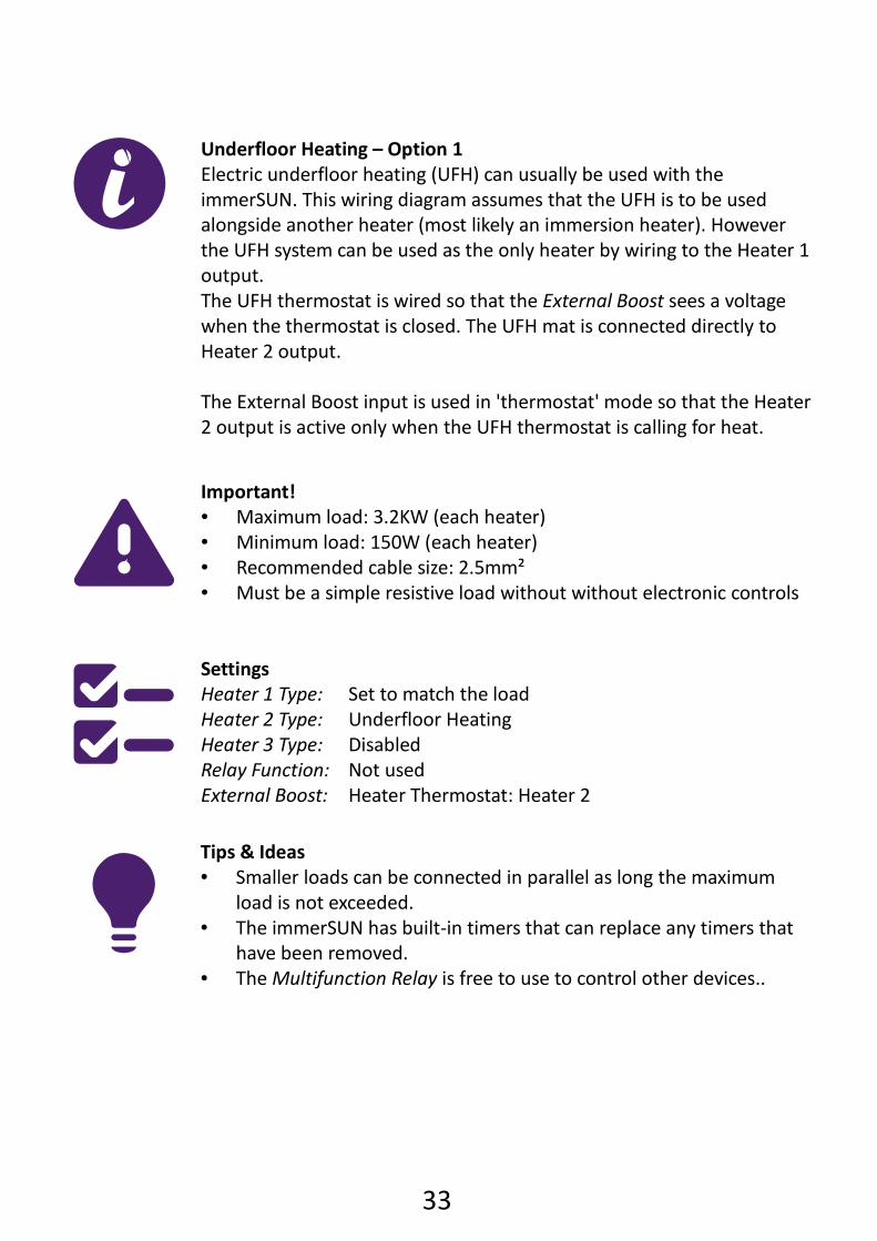
Underfloor Heating – Option 1
Electric underfloor heating (UFH) can usually be used with the
immerSUN. This wiring diagram assumes that the UFH is to be used
alongside another heater (most likely an immersion heater). However
the UFH system can be used as the only heater by wiring to the Heater 1
output.
The UFH thermostat is wired so that the External Boost sees a voltage
when the thermostat is closed. The UFH mat is connected directly to
Heater 2 output.
The External Boost input is used in 'thermostat' mode so that the Heater
2 output is active only when the UFH thermostat is calling for heat.
Important! Maximum load: 3.2KW (each heater) Minimum load: 150W (each heater) Recommended cable size: 2.5mm² Must be a simple resistive load without without electronic controls
Settings
Heater 1 Type: Set to match the load
Heater 2 Type: Underfloor Heating
Heater 3 Type: Disabled
Relay Function: Not used
External Boost: Heater Thermostat: Heater 2
Tips & Ideas Smaller loads can be connected in parallel as long the maximum
load is not exceeded. The immerSUN has built-in timers that can replace any timers that
have been removed. The Multifunction Relay is free to use to control other devices..
34
L
E
N
HEATER 2
L
E
N
LINE
IMMERSUN
L
E
N
HEATER 1
EX BST
NO
NC C
RELAY
L N E
L
5
LOAD
ISOLATOR
SUPPLY
ISOLATOR
3.2KW max.
UFH MAT
UFH
THERMOSTAT
HEATING DEVICE
& THERMOSTAT
3.2KW max.L N E
220-240VAC
SUPPLY
Wiring: Underfloor Heating (opt. 2)

35
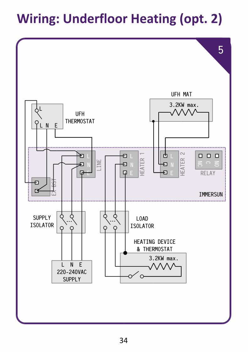
Underfloor Heating – Option 2
Electric underfloor heating (UFH) can usually be used with the
immerSUN. This wiring diagram assumes that the UFH is to be used
alongside an other heater (most likely an immersion heater). However
the UFH system can be used as the only heater by wiring to the Heater 1
output.
The UFH thermostat is wired solely to the immerSUN, power is taken
from the immerSUN supply and External Boost input is used to sense the
UFH thermostat state. The UFH mat is connected directly to Heater 2
output.
The External Boost input is used in 'thermostat' mode so that the Heater
2 output is active only when the UFH thermostat is calling for heat.
Important! Maximum load: 3.2KW (each heater) Minimum load: 150W (each heater) Recommended cable size: 2.5mm² Must be a simple resistive load without electronic controls
Settings
Heater 1 Type: Set to match the load
Heater 2 Type: Underfloor Heating
Heater 3 Type: Disabled
Relay Function: Not used
External Boost: Heater Thermostat: Heater 2
Tips & Ideas Smaller loads can be connected in parallel as long the maximum
load is not exceeded. The immerSUN has built-in timers that can replace any timers that
have been removed. The Multifunction Relay is free to use to control other devices.
36
Wiring: Dual Tariff (Single Meter)
37
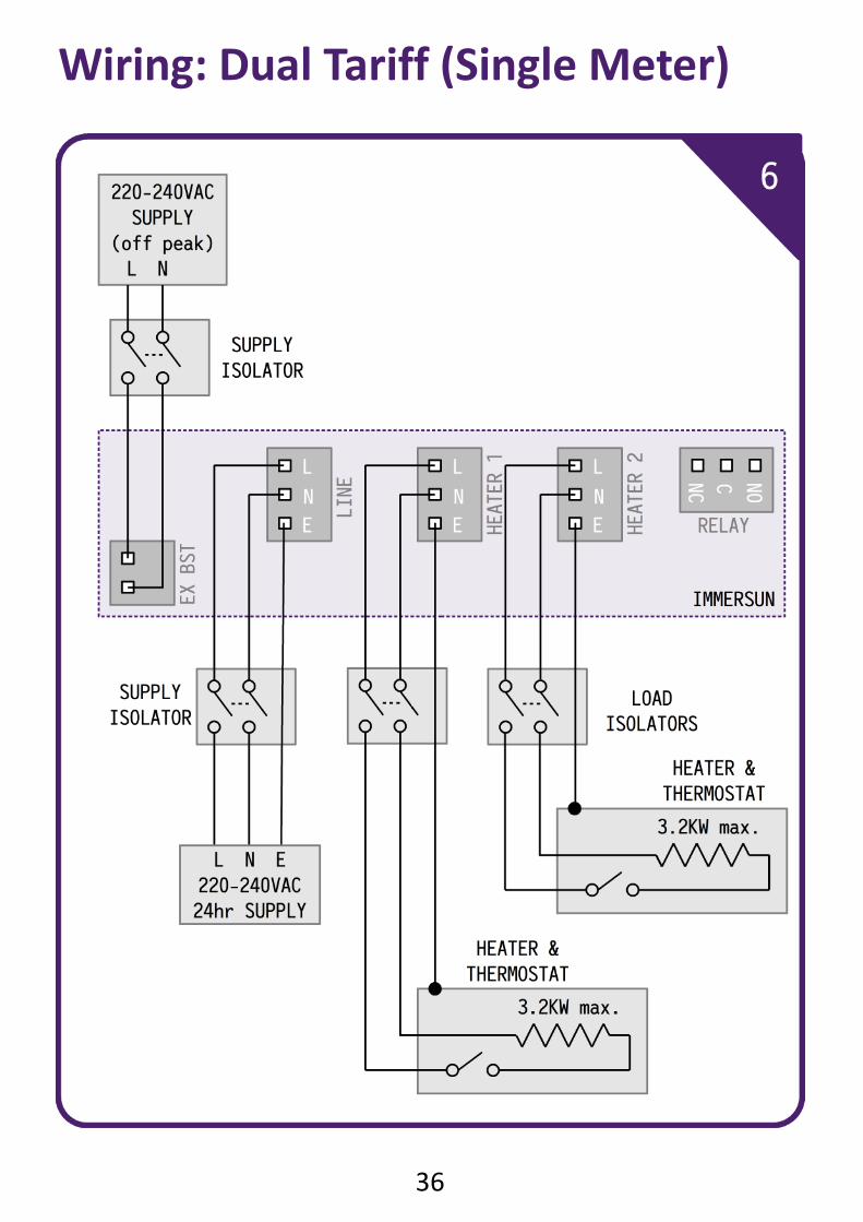
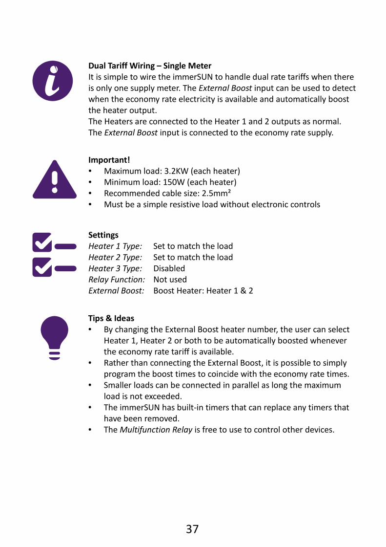
Dual Tariff Wiring – Single Meter
It is simple to wire the immerSUN to handle dual rate tariffs when there
is only one supply meter. The External Boost input can be used to detect
when the economy rate electricity is available and automatically boost
the heater output.
The Heaters are connected to the Heater 1 and 2 outputs as normal.
The External Boost input is connected to the economy rate supply.
Important! Maximum load: 3.2KW (each heater) Minimum load: 150W (each heater) Recommended cable size: 2.5mm² Must be a simple resistive load without electronic controls
Settings
Heater 1 Type: Set to match the load
Heater 2 Type: Set to match the load
Heater 3 Type: Disabled
Relay Function: Not used
External Boost: Boost Heater: Heater 1 & 2
Tips & Ideas By changing the External Boost heater number, the user can select
Heater 1, Heater 2 or both to be automatically boosted whenever
the economy rate tariff is available. Rather than connecting the External Boost, it is possible to simply
program the boost times to coincide with the economy rate times. Smaller loads can be connected in parallel as long the maximum
load is not exceeded. The immerSUN has built-in timers that can replace any timers that
have been removed. The Multifunction Relay is free to use to control other devices.
38
L
E
N
HEATER 2
L
E
N
LINE
IMMERSUN
L
E
N
HEATER 1
EX BST
NO
NC C
RELAY
Wiring: Dual Tariff (Two Meters)
7
3.2KW max.L N E
220-240VAC
24hr SUPPLY
HEATER &
THERMOSTAT
LOAD
ISOLATOR
3.2KW max.HEATER &
THERMOSTAT
A1
A2
1 3 5 7
2 4 6 8
220-240VAC
SUPPLY
(off peak)
L N
SUPPLY
ISOLATOR
2NO + 2NC
CONTACTOR
LN
39
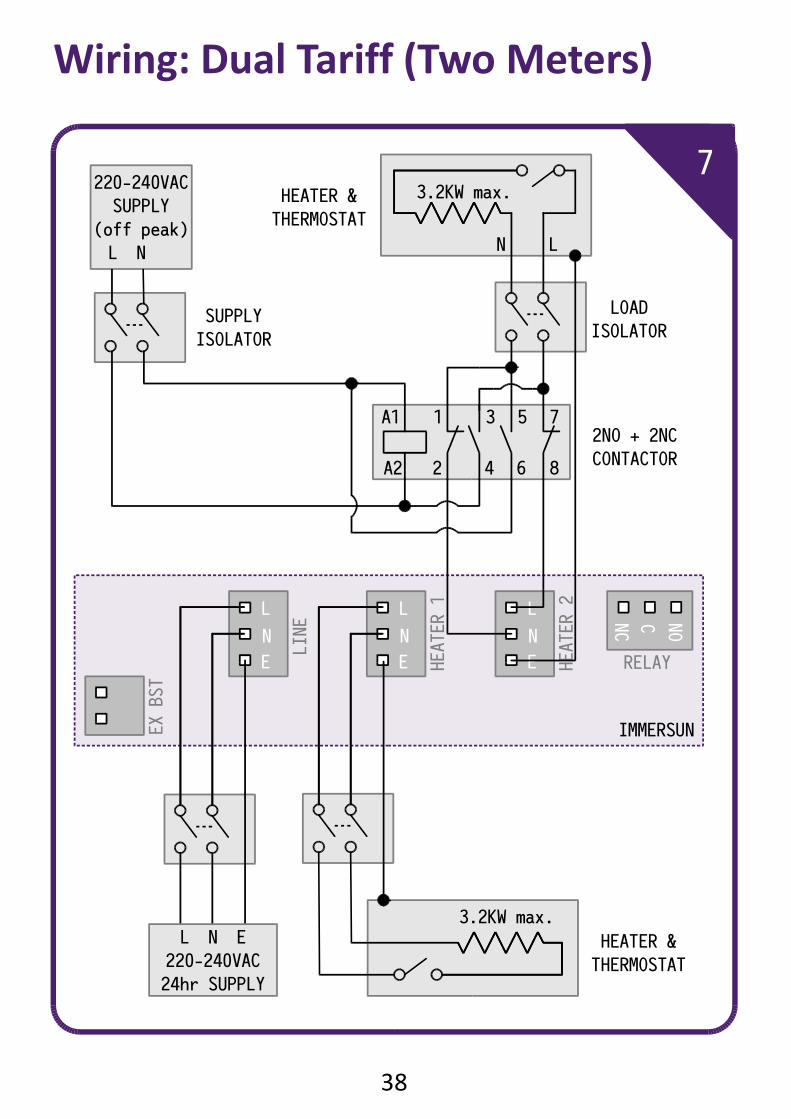
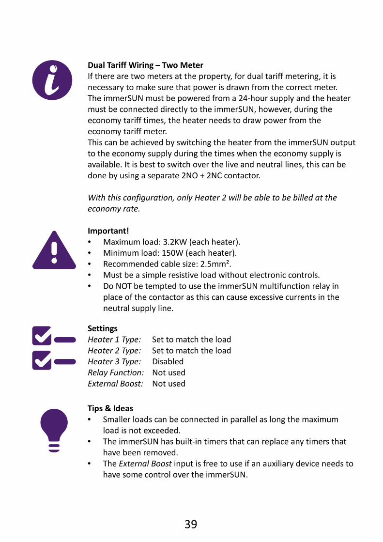
Dual Tariff Wiring – Two Meter
If there are two meters at the property, for dual tariff metering, it is
necessary to make sure that power is drawn from the correct meter.
The immerSUN must be powered from a 24-hour supply and the heater
must be connected directly to the immerSUN, however, during the
economy tariff times, the heater needs to draw power from the
economy tariff meter.
This can be achieved by switching the heater from the immerSUN output
to the economy supply during the times when the economy supply is
available. It is best to switch over the live and neutral lines, this can be
done by using a separate 2NO + 2NC contactor.
With this configuration, only Heater 2 will be able to be billed at the
economy rate.
Important! Maximum load: 3.2KW (each heater). Minimum load: 150W (each heater). Recommended cable size: 2.5mm². Must be a simple resistive load without electronic controls. Do NOT be tempted to use the immerSUN multifunction relay in
place of the contactor as this can cause excessive currents in the
neutral supply line.
Settings
Heater 1 Type: Set to match the load
Heater 2 Type: Set to match the load
Heater 3 Type: Disabled
Relay Function: Not used
External Boost: Not used
Tips & Ideas Smaller loads can be connected in parallel as long the maximum
load is not exceeded. The immerSUN has built-in timers that can replace any timers that
have been removed. The External Boost input is free to use if an auxiliary device needs to
have some control over the immerSUN.
40
ERROR 1
VOLTAGE BACK-FEED 1
Check:
Heater 1 wiring
ERROR 1
VOLTAGE BACK-FEED 1
Check:
Heater 1 wiring
ERROR 3
HEATER NOT DETECTED
Check:
Heater is ON
Thermostat is ON
ERROR 3
HEATER NOT DETECTED
Check:
Heater is ON
Thermostat is ON
ERROR 4
SENSOR ERROR
Check:
Sensor wiring
Sensor location
ERROR 4
SENSOR ERROR
Check:
Sensor wiring
Sensor location
ERROR 2
VOLTAGE BACK-FEED 2
Check:
Heater 2 wiring
ERROR 2
VOLTAGE BACK-FEED 2
Check:
Heater 2 wiring
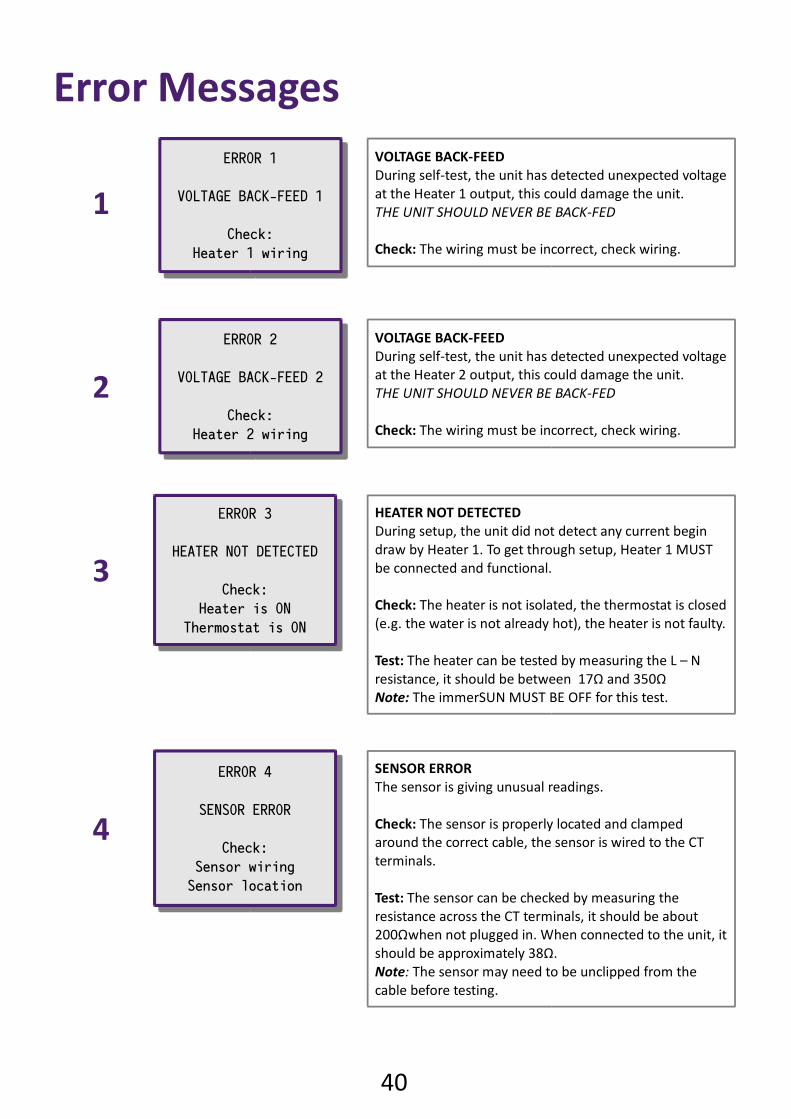
VOLTAGE BACK-FEED
During self-test, the unit has detected unexpected voltage
at the Heater 1 output, this could damage the unit.
THE UNIT SHOULD NEVER BE BACK-FED
Check: The wiring must be incorrect, check wiring.
1
2
VOLTAGE BACK-FEED
During self-test, the unit has detected unexpected voltage
at the Heater 2 output, this could damage the unit.
THE UNIT SHOULD NEVER BE BACK-FED
Check: The wiring must be incorrect, check wiring.
3
HEATER NOT DETECTED
During setup, the unit did not detect any current begin
draw by Heater 1. To get through setup, Heater 1 MUST
be connected and functional.
Check: The heater is not isolated, the thermostat is closed
(e.g. the water is not already hot), the heater is not faulty.
Test: The heater can be tested by measuring the L – N
resistance, it should be between 17Ω and 350Ω
Note: The immerSUN MUST BE OFF for this test.
4
SENSOR ERROR
The sensor is giving unusual readings.
Check: The sensor is properly located and clamped
around the correct cable, the sensor is wired to the CT
terminals.
Test: The sensor can be checked by measuring the
resistance across the CT terminals, it should be about
200Ωwhen not plugged in. When connected to the unit, it
should be approximately 38Ω.
Note: The sensor may need to be unclipped from the
cable before testing.
Error Messages
41
ERROR 5
INTERNAL FAULT
Contact installer
ERROR 5
INTERNAL FAULT
Contact installer
ERROR 6
UNIT OVERHEAT
Check:
Ventilation
ERROR 6
UNIT OVERHEAT
Check:
Ventilation
ERROR 7
OUTPUT OVERLOAD
Check:
Heater rating
ERROR 7
OUTPUT OVERLOAD
Check:
Heater rating
ERROR 8
LOAD SHORT-CIRCUIT
Check:
Heater
ERROR 8
LOAD SHORT-CIRCUIT
Check:
Heater
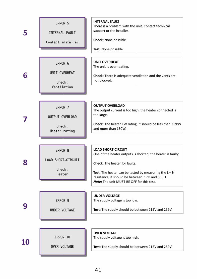
INTERNAL FAULT
There is a problem with the unit. Contact technical
support or the installer.
Check: None possible.
Test: None possible.
UNIT OVERHEAT
The unit is overheating.
Check: There is adequate ventilation and the vents are
not blocked.
OUTPUT OVERLOAD
The output current is too high, the heater connected is
too large.
Check: The heater KW rating, it should be less than 3.2kW
and more than 150W.
LOAD SHORT-CIRCUIT
One of the heater outputs is shorted, the heater is faulty.
Check: The heater for faults.
Test: The heater can be tested by measuring the L – N
resistance, it should be between 17Ω and 350Ω
Note: The unit MUST BE OFF for this test.
5
6
7
8
ERROR 9
UNDER VOLTAGE
ERROR 9
UNDER VOLTAGE
UNDER VOLTAGE
The supply voltage is too low.
Test: The supply should be between 215V and 259V.9
ERROR 10
OVER VOLTAGE
ERROR 10
OVER VOLTAGE
OVER VOLTAGE
The supply voltage is too high.
Test: The supply should be between 215V and 259V.10
42
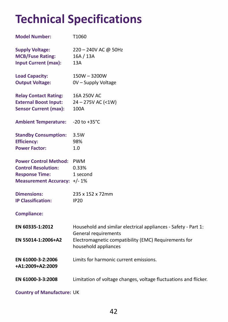
Technical Specifications
Model Number: T1060
Supply Voltage: 220 – 240V AC @ 50Hz
MCB/Fuse Rating: 16A / 13A
Input Current (max): 13A
Load Capacity: 150W – 3200W
Output Voltage: 0V – Supply Voltage
Relay Contact Rating: 16A 250V AC
External Boost Input: 24 – 275V AC (<1W)
Sensor Current (max): 100A
Ambient Temperature: -20 to +35°C
Standby Consumption: 3.5W
Efficiency: 98%
Power Factor: 1.0
Power Control Method: PWM
Control Resolution: 0.33%
Response Time: 1 second
Measurement Accuracy: +/- 1%
Dimensions: 235 x 152 x 72mm
IP Classification: IP20
Compliance:
EN 60335-1:2012 Household and similar electrical appliances - Safety - Part 1:
General requirements
EN 55014-1:2006+A2 Electromagnetic compatibility (EMC) Requirements for
household appliances
EN 61000-3-2:2006 Limits for harmonic current emissions.
+A1:2009+A2:2009
EN 61000-3-3:2008 Limitation of voltage changes, voltage fluctuations and flicker.
Country of Manufacture: UK