Embed Size (px)
Citation preview

landscape · entertainment ·architectural · hospitality · illumination
®
UL 1838 UL 1598
Installation & User Guide RXT Series Transformers & Controls
MATERIAL & FEATURES: • UL1838listed,thestandardforlowvoltagelandscapelightingsystems• 60,120,180,300and600wattoutputmodels• MultiVoltageoutput(12.5,13.5&14.5Volts)• SuperTerminalLugswithcapacityof3x#8,5x#10,7x#12or9x#14gaugewire• 304StainlessSteelenclosurewithNo.4brushedfinish• Removablehingeddoorislockableandweathersealed• Abovegrade,NEMA3Rrated,raintightenclosure• LEDindicatorsforinstantrecognitionof120vand12vpower• TimerReadystandard(forplugintimers)• OptionalMechanicalTimer(-T),DigitalTimer(-DT)andAstroTimer(-AT)faceplates
canbefactoryorfieldinstalled• PhotocellReadywithquickconnector(notwith-ATmodel)• Suppliedwithtwo1/2”conduit(tradesize)holes&one1-1/2”inletwithplugsin
bottompanelplus2sidepanel1/2”conduit(tradesize)holeswithplugs• Breakawaybottompanelswingsdownforeasyaccesswiring• 11gaugecoldrolledsteel‘L’bracketsforstablemounting• Mountingplateandhardwareincluded
ELECTRICAL: • Longlife,highefficiency266°F(130°C)class‘B’ratedtransformercore• CopperShieldedisolation/insulation;Nocontactbetween120v(primary)and
12v(secondary)windings• 1500vIsolationbetweenallwindingsandground• GradeM19electricgradesteelforsuperiorelectricalandmagneticproperties• Singlephase,opencoreandcoil• E.I.laminatedcorehasconcentricwindingandisprotectedbyinternalautomatic
resettablethermalswitch.• Doublevacuumedimpregnatedwithblackslateflour• Filledvarnishforsuperiorheatdissipationandnoisereduction-Class180°C• 120vprimary,12.5vsecondary50/60Hertz/cycle(standard)• 6foot18/3SJT-WAweatherproofgroundedpowercord(120v)• ON/OFFcontrolviarockerswitchon120vside,noidleenergyconsumptionornoise
whenpowerisOff.• Manuallyresettablecircuitbreakerforoverloadandshortcircuitprotection• Extraheavyduty(80amp)terminallugs
TimerReady(Standard)
AstroTimer(-AT)
DigitalTimer(-DT)
INTERTEK
LISTED
ETLListedtoULStandardsForSafety
5.5"140mm
4.25"108mm
12"305mm
5.5"140mm
12"305mm
RXT- 12-60-MVRXT- 12-120-MVRXT- 12-180-MV
RXT- 12-60-MVRXT- 12-120-MVRXT- 12-180-MV
BOTTOM PANEL KNOCKOUTS
2X 1/2” (trade size) Plugged Knockouts
1-1/2” Plugged Inlet
6.5"165mm
5"127mm
15"381mm
RXT- 12-300-MVRXT- 12-600-MV
2
MountingBracket 4Screws
Mounting Your Transformer
Super Terminal Lug System
Circuit Breakers
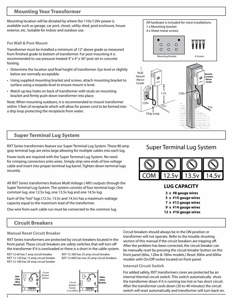
Allhardwareisincludedformostinstallations:1xMountingbracket4xSheetmetalscrews
Mountinglocationwillbedictatedbywherethe110v/120vpowerisavailablesuchasgarage,carport,closet,utilityshed,poolenclosure,houseexterior,etc.Suitableforindoorandoutdooruse.
For Wall & Post MountTransformermustbeinstalledaminimumof12”abovegradeasmeasuredfromfinishedgradetobottomoftransformer.Forpostmountingitisrecommendedtousepressuretreated4”x4”x36”postsetinconcretefooting.
• Determinethelocationandfinalheightoftransformer.Eyelevelorslightlybelowarenormallyacceptable.
• Usingsuppliedmountingbracketandscrews,attachmountingbrackettosurfaceusingatorpedoleveltoensuremountislevel.
• Matchupkeyholesonbackoftransformerwithstudsonmountingbracketandfirmlypushdowntransformerintoplace.
Note:Whenmountingoutdoors,itisrecommendedtomounttransformerwithin3feetofreceptaclewhichwillallowforpowercordtobeformedintoadriploopprotectingthereceptaclefromwater.
Manual Reset Circuit BreakerRXTSeriestransformersareprotectedbycircuitbreakerslocatedinthefrontpanel.Thesecircuitbreakersaresafetyswitchesthatwillturnoffthetransformerifitisoverloadedorthereisashortinthecablesystem.RXT-12-60has7ampcircuitbreaker RXT-12-300has25ampcircuitbreakerRXT-12-120has13ampcircuitbreaker RXT-12-600hastwo25ampcircuitbreakersRXT-12-180has20ampcircuitbreaker
CircuitbreakersshouldalwaysbeintheONpositionortransformerwillnotoperate.Refertothetroubleshootingsectionofthismanualifthecircuitbreakersaretrippingoff.Aftertheproblemhasbeencorrected,thecircuitbreakercanbemanuallyresetbypressingthecircuitbreakerbuttononthefrontpanel(60w,120w&180wmodels.)Reset300wand600wmodelswithOn/Offrockerlocatedonfrontpanel.
Internal Circuit SwitchForaddedsafety,RXTtransformerscoresareprotectedbyaninternalthermalcircuitswitch.Thisswitchautomaticallyshutsthetransformerdownifitisrunningtoohotorhasshortcircuit.Afterthetransformercoolsdown(20to40minutes)thecircuitswitchwillresetautomaticallyandtransformerwillturnbackon.
RXTSeriestransformersfeatureourSuperTerminalLugSystem.These80ampgrayterminallugsareextralargeallowingformultiplecablesintoeachlug.
FewertoolsarerequiredwiththeSuperTerminalLugSystem.Noneedforcrimpingconnectorsontowires.Simplystripwireendsoflowvoltagecableandinsertintoproperterminallugbarrel.Tightendownterminallugssecurely.
AllRXTSeriestransformersfeatureMultiVoltage(-MV)outputsthroughtheSuperTerminalLugSystem.Thesystemconsistsoffourterminallugs:Onecommonlug,one12.5vlug,one13.5vlugandone14.5vlug.
Eachofthe“hot”lugs(12.5v,13.5vand14.5v)hasamaximumwattagecapacityequaltothemaximumloadofthetransformer.
Onewirefromeachcablerunmustbeconnectedtothecommonlug.
Remote LocationAbove Grade
Remote LocationAbove Grade
Super Terminal Lug System
12.5v 13.5vCOM 14.5v
LUG CAPACITY 3 x #8 gauge wires 5 x #10 gauge wires 7 x #12 gauge wires 9 x #14 gauge wires12 x #16 gauge wires
OFF
ON
CircuitBreakerButton
CircuitBreakerRocker
(2 on 600w)
CircuitBreakerButton
CircuitBreaker
Rocker Switch
OFF
ON
OFF
ON
60w120w180w
Models
300w600w
Models
OFF
ON
CircuitBreakerButton
CircuitBreakerRocker
(2 on 600w)
CircuitBreakerButton
CircuitBreaker
Rocker Switch
OFF
ON
OFF
ON
60w120w180w
Models
300w600w
Models

3
Installation & Operating Instructions
Timer Ready (standard base model)NoinstallationisrequiredforstandardbasemodelRXTtransformerswhichcomestandardwithaPlug-inTimerReadyreceptacle.
Pluggroundedpowercordintooutlet;GroundFaultInterrupteroutlet(GFIC)recommended.GreenLEDindicatoronfrontpanelunderOn/Offswitchwilllightupconfirming120vpowertotransformer.
Tooperate:pressrockerswitchto“ON”or“OFF”positiontoturnlightsonandoff.GreenLEDindicatorlightnexttoterminallugswillilluminatewhen12vpowertolightsison.LEDindicatorlightwillgooffwhen12vpoweristurnedoff.
Photocell & Remote PhotocellPhotocellsmusthavefullaccesstodaylight.Anyobstructioncouldaffectoperationofunit.
1. UnplugtransformerpriortoinstallationofPhotocell.2. Onfrontpanel,removewhitemaleplugwithBlackjumper wirefromPhotocellReadyblock.(Donotdiscardmaleplug asitcanbeusedforload/amperecheck.)3. Determinewhichsideoftransformerhasfullaccessto unobstructeddaylightandremoveblackplugfromthatside oftransformer.UseRemotePhotocelliftransformerdoesnot haveaccesstounobstructeddaylight.4. RemovelocknutfromPhotocell;runplugandwiresfrom Photocellthroughhole;replaceandtightenlocknutto securePhotocelltohousing.Connectmaleplugfrom Photocelltowhitefemaleconnectoronfrontplate.
5. Plugtransformerbackinandpoweron.IfaTimerisinstalled,setTimerpermanentlyto“On”positionforlightsonatduskandoffatdawn.TohavelightsturnedonbyphotocellandturnedoffbyTimerataspecifictime,forexamplemidnight,setTimertoturnOnat12noon(PhotocellwilloverrideTimerandnotallowpowertolightsuntildusk)andsettimertotimeforlightstoturnoff.
Plug In Timer (supplied by others)UnplugTimerReadyplugfromreceptacleonfrontpanel.PlugintheTimer(suppliedbyothers)tothereceptacleonfrontpanel.InsertTimerReadyplugintoproperreceptacleonTimerandturntransformeron.Followmanufacturer’sinstructionsforoperationoftheTimer.
Removing Timer Ready plate for installation of Integral Timer (-T) Digital Timer (-DT) or Astro Timer (-AT)IfIntegralTimer,DigitalTimerorAstroTimerwasinstalledatthefactory,skiptheseremovalandinstallationinstructions.
1. UsingPhillips#2screwdriver,removethree screwsonfaceofTimerReadyplate.2. Gentlyliftplateofftoexposewires.3. Unplugquickconnectofblackandwhitewire frompowercordtoreceptacle.4. Unplugquickconnectofwhitewirefrom PhotocellReadyBlocktotransformercore5. Unplugquickconnectofblackwirefrom OnOffSwitchtotransformercore.6. Removeentireplate.
OFF
ON
RECEPTACLE
SWITCH
PHOTOCELLREADY BLOCK
OFF
ON
PLUG
REMOVING TIMER READY PLATE
1. Remove three Phillips #2 screws on face of Timer Ready plate.2. Gently lift plate off to expose wires.3. Unplug quick connect of black and white wire from power cord to receptacle.4. Unplug quick connect of white wire from PC Ready Block to transformer core5. Unplug quick connect of black wire from On/Off Switch to transformer core.6. Remove entire plate.
F FF
M M
F
TO CIRCUIT BREAKER
TO TERMINAL BLOCK
TRANSFORMERCORE
120VPOWERCORD
BLACK
WHITE
RED
GREEN TO GROUND
BLACK
BLACK
WHITEWHITE
WHITE
BLACK
BLA
CK
WH
ITE
Timer ReadyReceptacle
LED Indicator120v Power
On/OffRocker Switch
LED Indicator12v Power
Timer ReadyPlug
GR
EEN
TO
GR
OU
ND
GND
GND
OFF
ON
Timer Inserts Into Receptacle & Timer Ready
Plug Inserts IntoSide Of Timer
OFF
ON
RECEPTACLE
SWITCH
PHOTOCELLREADY BLOCK
OFF
ON
PLUG
REMOVING TIMER READY PLATE
1. Remove three Phillips #2 screws on face of Timer Ready plate.2. Gently lift plate off to expose wires.3. Unplug quick connect of black and white wire from power cord to receptacle.4. Unplug quick connect of white wire from PC Ready Block to transformer core5. Unplug quick connect of black wire from On/Off Switch to transformer core.6. Remove entire plate.
F FF
M M
F
TO CIRCUIT BREAKER
TO TERMINAL BLOCK
TRANSFORMERCORE
120VPOWERCORD
BLACK
WHITE
RED
GREEN TO GROUND
BLACK
BLACK
WHITEWHITE
WHITE
BLACK
BLA
CK
WH
ITE
Timer ReadyReceptacle
LED Indicator120v Power
On/OffRocker Switch
LED Indicator12v Power
Timer ReadyPlug
GR
EEN
TO
GR
OU
ND
GND
GND
Wiring Diagram for Removal of Timer Ready Plate
OFF
ON
PhotocellReadyBlock
Photocell
OFF
ON
Remote Photocell
Shownw/PlugInTimer

4
Installation & Operating Instructions (continued)
Installing Integral Timer (-T) plateNospecialtoolsrequired.Male/FemalequickconnectorsareincludedwiththewiringinsidetransformerandwithwiringonIntegralTimerplate.
1. ConnectBlackwirefrom#1onDigitalTimerto Blackwirefrompowercord.2. ConnectfirstsplitWhitewirefrom#2onDigital TimertoWhitewirefrompowercord.3. ConnectsecondsplitWhitewirefrom#2on DigitalTimertoWhitewirefromtransformer core.4. ConnectBlackwirefromOn/OffSwitchtoBlack wirefromtransformercore.5. CarefullyfitDigitalTimerplateintotransformer beingcarefulnottopinchanywires.6. UsingPhillips#2screwdriver,install3supplied screwsandtightenfirmly.
GREEN TO GROUND
GND
OFF
ON
INSTALLING INTEGRAL TIMER (-T) PLATE
1. Connect Black wire from #1 on Digital Timer to Black wire from power cord.2. Connect first split White wire from #2 on Digital TImer to White wire from power cord.3. Connect second split White wire from #2 on Digital Timer to White wire from transformer core.4. Connect Black wire from On/Off Switch to Black wire from transformer core.5. Carefully fit Digital Timer plate into transformer being careful not to pinch any wires.6. Using Pillips #2 screwdriver intall 3 supplied screws and tighten firmly.
Minute Hand
Inner Ring
Outer Ring
PHOTOCELLREADY BLOCK
F
TO CIRCUIT BREAKER
TO TERMINAL BLOCK
TRANSFORMERCORE
FM
FM
M
F
F
SWITCH
OFF
ON
120VPOWERCORD
RED
GR
EEN
TO
GR
OU
ND
WHITE
BLACK
BLACK
WHITE
WHITE
WH
ITE
BLA
CK
WHITE
BLACK
BLACK
BROWN
F F F F
TO LED
TO LED
GREEN
GREEN
INTEGRAL TIMER
1234
GND
Wiring Diagram for Installation of Integral Timer Plate
Integral Timer operation
Setting Current TimeTosetthecurrenttimeturntheminutehandclockwise.
DONOTSETTHETIMEBYROTATINGTHE“OUTER”DIAL.
DONOTROTATETHEMINUTEHANDCOUNTERCLOCKWISEASTHISWILLDAMAGETHEGEARS.
Turntheminutehandclockwiseuntilthetimeofdayontheouterdialisalignedwiththetrianglemarkerontheinnerdial(locatedatthetwoo’clockposition)
ProgrammingThe24-Hourdialhasquarter-hour(15minute)divisionsandAM/PMindications.Beforeproceedingmakesureallofthewhitecaptivetrippersarepushedtotheinsideringposition.Programthetimeswitchbypushingthewhitecaptivetripperstotheouterringpositionfortheentire“lightson”time.(Eachwhitecaptivetrippercontrols15minutesoftime.)Forexample,ifyouwantlightstoturnonat6:30pmandturnoffat11pm,allthewhitecaptivetrippersbetween6:30pmand11pmshouldbepushedtotheouterringposition.
GREEN TO GROUND
GND
OFF
ON
INSTALLING INTEGRAL TIMER (-T) PLATE
1. Connect Black wire from #1 on Digital Timer to Black wire from power cord.2. Connect first split White wire from #2 on Digital TImer to White wire from power cord.3. Connect second split White wire from #2 on Digital Timer to White wire from transformer core.4. Connect Black wire from On/Off Switch to Black wire from transformer core.5. Carefully fit Digital Timer plate into transformer being careful not to pinch any wires.6. Using Pillips #2 screwdriver intall 3 supplied screws and tighten firmly.
Minute Hand
Inner Ring
Outer Ring
PHOTOCELLREADY BLOCK
F
TO CIRCUIT BREAKER
TO TERMINAL BLOCK
TRANSFORMERCORE
FM
FM
M
F
F
SWITCH
OFF
ON
120VPOWERCORD
RED
GR
EEN
TO
GR
OU
ND
WHITE
BLACK
BLACK
WHITE
WHITE
WH
ITE
BLA
CK
WHITE
BLACK
BLACK
BROWN
F F F F
TO LED
TO LED
GREEN
GREEN
INTEGRAL TIMER
1234
GND
5
Installation & Operating Instructions (continued)
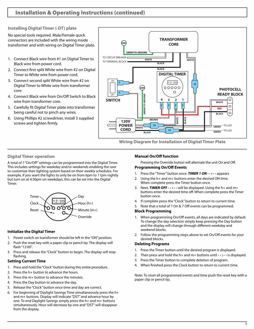
Installing Digital Timer (-DT) plateNospecialtoolsrequired.Male/FemalequickconnectorsareincludedwiththewiringinsidetransformerandwithwiringonDigitalTimerplate.
1. ConnectBlackwirefrom#1onDigitalTimerto Blackwirefrompowercord.2. ConnectfirstsplitWhitewirefrom#2onDigital TimertoWhitewirefrompowercord.3. ConnectsecondsplitWhitewirefrom#2on DigitalTimertoWhitewirefromtransformer core.4. ConnectBlackwirefromOn/OffSwitchtoBlack wirefromtransformercore.5. CarefullyfitDigitalTimerplateintotransformer beingcarefulnottopinchanywires.6. UsingPhillips#2screwdriver,install3supplied screwsandtightenfirmly.
GREEN TO GROUND
GND
OFF
ON
INSTALLING DIGITAL TIMER (-TR) PLATE
1. Connect Black wire from #1 on Digital Timer to Black wire from power cord.2. Connect first split White wire from #2 on Digital Timer to White wire from power cord.3. Connect second split White wire from #2 on Digital Timer to White wire from transformer core.4. Connect Black wire from On/Off Switch to Black wire from transformer core.5. Carefully fit Digital Timer plate into transformer being careful not to pinch any wires.6. Using Pillips #2 screwdriver intall 3 supplied screws and tighten firmly.
Timer Day
Hour (h+)
Minute (m+)
Override
Clock
Reset
PHOTOCELLREADY BLOCK
F
TO CIRCUIT BREAKER
TO TERMINAL BLOCK
TRANSFORMERCORE
DIGITAL TIMER
1234
FM
FM
M
F
F
SWITCH
OFF
ON
120VPOWERCORD
RED
GR
EEN
TO
GR
OU
ND
WHITE
BLACK
BLACK
WHITE
WHITE
WH
ITE
BLA
CK
WHITE
BLACK
BLACK
BROWN
F F F F
TO LED
TO LED
GREEN
GREEN
GND
Wiring Diagram for Installation of Digital Timer Plate
Digital Timer operationAtotalof7“On/Off”settingscanbeprogrammedintotheDigitalTimer.Thisincludessettingsforweekdayand/orweekendsenablingtheusertocustomizetheirlightingsystembasedontheirweeklyschedules.Forexample,ifyouwantthelightstoonlybeonfrom6pmto11pmnightlybutturnonat4:30pmonweekdays,thiscanbesetintotheDigitalTimer.
Initialize the Digital Timer1. Powerswitchontransformershouldbeleftinthe“ON”position.2. Pushtheresetkeywithapapercliporpenciltip.Thedisplaywill flash“12:00”.3. Pressandreleasethe“Clock”buttontobegin.Thedisplaywillstop flashing.Setting Current Time1. Pressandholdthe“Clock”buttonduringthisentireprocedure.2. Presstheh+buttontoadvancethehours.3. Pressthem+buttontoadvancetheminutes.4. PresstheDaybuttontoadvancetheday.5. Releasethe“Clock”buttononcetimeanddayarecorrect.6. ForbeginningofDaylightSavingsTimesimultaneouslypresstheh+ andm+buttons.Displaywillindicate“DST”andadvancehourby one.ToendDaylightSavingssimplypresstheh+andm+buttons simultaneously.Hourwilldecreasebyoneand“DST”willdisappear fromthedisplay.
Manual On/Off function PressingtheOverridebuttonwillalternatetheunitOnandOff.Programming On/Off Events1. Pressthe“Timer”buttononce.TIMER 1 ON - - : - -appears2. Usingtheh+andm+buttonsenterthedesiredONtime. WhencompletepresstheTimerbuttononce.3. Next,TIMER OFF - - : - -willbedisplayed.Usingtheh+andm+ buttonsenterthedesiredtimeoff.WhencompletepresstheTimer buttononce.4. Ifcompletepressthe“Clock”buttontoreturntocurrenttime.5. Notethatatotalof7On&7Offeventscanbeprogrammed.Block Programming1. WhenprogrammingOn/Offevents,alldaysareindicatedbydefault. TochangethedayselectionsimplykeeppressingtheDaybutton andthedisplaywillchangethroughdifferentweekdayand weekendblocks.2. FollowtheprogrammingstepsabovetosetOn/Offeventsforyour desiredblocks.Deleting Programs1. PresstheTimerbuttonuntilthedesiredprogramisdisplayed.2. Thenpressandholdtheh+andm+buttonsuntil- - : - -isdisplayed.3. PresstheTimerbuttontocompletedeletionofprogram.4. WhenfinishedpresstheClockbuttontoreturntocurrenttime.
Note:Toresetallprogrammedeventsandtimepushtheresetkeywithapapercliporpenciltip.
GREEN TO GROUND
GND
OFF
ON
INSTALLING DIGITAL TIMER (-TR) PLATE
1. Connect Black wire from #1 on Digital Timer to Black wire from power cord.2. Connect first split White wire from #2 on Digital Timer to White wire from power cord.3. Connect second split White wire from #2 on Digital Timer to White wire from transformer core.4. Connect Black wire from On/Off Switch to Black wire from transformer core.5. Carefully fit Digital Timer plate into transformer being careful not to pinch any wires.6. Using Pillips #2 screwdriver intall 3 supplied screws and tighten firmly.
Timer Day
Hour (h+)
Minute (m+)
Override
Clock
Reset
PHOTOCELLREADY BLOCK
F
TO CIRCUIT BREAKER
TO TERMINAL BLOCK
TRANSFORMERCORE
DIGITAL TIMER
1234
FM
FM
M
F
F
SWITCH
OFF
ON
120VPOWERCORD
RED
GR
EEN
TO
GR
OU
ND
WHITE
BLACK
BLACK
WHITE
WHITE
WH
ITE
BLA
CK
WHITE
BLACK
BLACK
BROWN
F F F F
TO LED
TO LED
GREEN
GREEN
GND

6
Installation & Operating Instructions (continued)
Installing Astro Timer (-AT) plateNospecialtoolsrequired.Male/FemalequickconnectorsareincludedwiththewiringinsidetransformerandwithwiringonAstroTimerplate.
1. ConnectBlackwirefromAstroTimertoBlack wirefrompowercord.2. ConnectfirstsplitWhitewirefromAstro TimertoWhitewirefrompowercord.3. ConnectsecondsplitWhitewirefromAstro TimertoWhitewirefromtransformercore.4. ConnectBluewirefromAstroTimertoBlack wirefromtransformercore.5. ConnectGreengroundwirefrompowercord toGreenwirefromtransformercore.6. CarefullyfitAstroTimerplateintotransformer beingcarefulnottopinchanywires.7. UsingPhillips#2screwdriver,install3supplied screwsandtightenfirmly.
GREEN TO GROUND
GND
INSTALLING ASTRO TIMER (-AR) PLATE
1. Connect Black wire from Astro Timer to Black wire from power cord.2. Connect first split White wire from Astro Timer to White wire from power cord.3. Connect second split White wire from Astro Timer to White wire from transformer core.4. Connect Blue wire from Astro Timer to Black wire from transformer core.5. Carefully fit Astro Timer plate into transformer being careful not to pinch any wires.6. Using Pillips #2 screwdriver intall 3 supplied screws and tighten firmly.
F
TO CIRCUIT BREAKER
TO TERMINAL BLOCK
TRANSFORMERCORE
FM
MFM
ASTRO TIMER
FM120V
POWERCORD
BLU
E
WH
ITE
BLACK
WHITEWHITE
WHITE
BLA
CK
WHITE
BLACK
BLACK
GND
GR
EEN
TO
GR
OU
ND
Wiring Diagram for Installation of Astro Timer Plate
Astro Timer operationTheAstroTimerfeaturesautomaticsunrise/sunsetactivationbasedonyourlongitudeandlatitudecoordinates.ItautomaticallyadjustsforDaylightSavingsTimeandneverneedsreprogramming.Builtinmemoryprotectssettingsduringapowerfailure.
Below are basic set up instructions. Please refer to the full Astro Timer User Guide included with transformer and/or Astro Timer plate.
Quick Start-upBydefaulttheAstroTimerwillturnlightsonatsunsetandturnthemoffat11:00pm.Ifthesesettingareappropriateforyouthenyouonlyneedtosetthetime,dayandlatitude/longitudecoordinates.
Operating ModesManualMode:Brieflypressthemainbuttontoturnthelightsonoroff.
AutomaticMode:Inthismodethetimerfollowsthesetprograms
Setting the Clock1. Pressthemainbuttonfor3secondstoenterthesetupmenusand navigatetotheTimeMenu.2. UsetheTimeMenutoselectthetimeformat(12-houror24-hour) andtosettheclockanddate.Daylight Savings TimeDaylightSavingsfunctionisenabledbydefault(DLSOn).ToturnoffDaylightSavingsTimeconsulttheAstroTimerUsersGuide.
Latitude/Longitude Coordinates1. Findthecoordinatesofyourcityornearestcityusingthesupplied tableintheAstroTimerUserGuideorgotowww.itouchmap.com tofindyourprecisecoordinatesbasedonyouraddress.2. Enteryourcoordinates. NOTE:Enteranegativevalueforasouthlatitudeorwestlongitude.
Programming the ScheduleYoucanselectupto21“On”programs(P01OntoP21On)and21“Off”programs(P01OfftoP21Off).Afterselectingeachprogram,settheday(s)fortheprogram.Youcanselectaspecificday,all7daysor“none”.Choose“none”foranyunusedprogram.
PleaserefertotheAstroTimerUserGuidetosettheprogramstartandendtimesanddifferentprogrammingoptionsforindividualdaysorweekends.
P02Mo
Off
AM
Indicates Modeof Operation
IndicatesKeypad locked
IndicatesTime & Day
IndicatesCurrent Program
Main buttonpress this buttonto manually turnlights on or off
The icon indicates the current program has been activated at sunset
The icon indicates the current program has been activated at sunrise
Indicates load On/Off state
Press this button to display today’s sunrise time
Press this button to display today’s sunset time
LED illuminates when the load state is on.

7
Using Multi Volt Taps
Installation Layouts
Maximumlamplifeandconsistentlightoutputisachievedwhenprovidingbetween11voltsand12voltstoeachfixture.Usingtherightgaugewireforthedistanceoftherun,groupingfixturesintozonesandtappingupto13.5vor14.5vforlongerdistancezoneswillaccomplishthis.
RXTTransformersfeature12.5v,13.5vand14.5vtapsallowingforpropervoltagetobeappliedtoeachzone.Thediagramattherightisageneralizationofthemultivoltagesystemsetup.
Otherfactorstoconsiderare:
• Totalwattageoneachrun
• Wiregaugebeingused
• Layoutoftheinstallation(seeInstallationLayoutsbelow)
• LEDlightingallowsforgreaterdistanceonrunsandlowerresistance
Note:Focusrecommendsallinstallationstobeperformedbyacertifiedlandscapecontractor.
LoopThisissimilartotheStraightRunlayoutexceptthereisanextralengthofcableconnectingthelastfixtureintherunbacktothetransformer.Sincevoltagedropiscomingfrombothsidesoftherunitwillproducemoreuniformvoltagetothefixtures.
Note:Youmustconnectthesamewireleadsonbothendsoftheruntothesametransformerterminalsonthesamecircuit.Markendofthecablebeforeinstallationsowhenitcomesbacktothetransformerthecorrectwiresareconnectedtothecorrectterminals.
Straight RunThisisthesimplestbutleastefficientlayoutmethod.Morevoltageissuppliedtothefirstfixtureontherunandeachfixturefollowingwillreceivelessandlessvoltageduetovoltagedrop.Thismethodisadequateforshortrunswherevoltagedifferenceisnotmorethan1.5voltsfromfirsttolastfixture.
Split LoadThismethodcenterfeedsthecablerunandreducesthevoltagedifferencebetweenthefirstandlastfixtureoneithersideoftherun.Thismethodisrecommendedbecauseitiseasytoinstallandminimizesvoltagedropbetweenfixtures.
OFF
ON
ZONE 2MID RANGE
Fixtures 50 - 100 feet from transformer
13.5 VOLT TAP
ZONE 1CLOSE RANGE
Fixtures less than 50 feetfrom transformer
12.5 VOLT TAP
12.5v 13.5vCOM 14.5v
ZONE 3LONG RANGE
Fixtures 100 - 150 feet from transformer
14.5 VOLT TAP
OFF
ON
FirstFixture
LastFixture
OFF
ON
FirstFixture
LastFixture
OFF
ON
FirstFixture
FirstFixture
LastFixture
LastFixture
OFF
ON
FirstFixture
LastFixture
OFF
ON
FirstFixture
LastFixture
OFF
ON
FirstFixture
FirstFixture
LastFixture
LastFixture
OFF
ON
FirstFixture
LastFixture
OFF
ON
FirstFixture
LastFixture
OFF
ON
FirstFixture
FirstFixture
LastFixture
LastFixture
Special Notes
Note1:Voltagedropisinherentinalllightingsystems.Alwaysusepropersizecable.Whenpossible,centerthetransformer&minimizeyourcabledistance.Makemultiplecablerunstoachieveyourdesiredcoverage.Themorecopper,thelessvoltagedrop.Useavoltmeterwhenmakingtheinstallationtoinsurethatvoltagesuppliedtoeachfixturedoesnotexceed12v.
Note2:Remembertoplanaheadforgrowthoradditions.Alwaysusealargersizetransformerorleaveroomonyourcurrentoneforaddingmorefixturesorincreasinglightwattage.Bydoingthisyouwillbeabletobuildupyourlightoutputasyouaddmorefixturestoyourlandscape.Replacelightbulbsquicklywhentheyburnout,otherwiseahighervoltagewillbesuppliedtoremainingfixturesduetoreducedload/resistance.Thisisextremelyimportantwhenusingmulti-voltagetransformers.

©2011FOCUSINDUSTRIES,INC.®FSA-PM-01007
Focus Industries, Inc.25301 Commercentre DriveLake Forest, CA 92630 USAwww.focusindustries.com
Phone: (949) 830-1350Toll Free: (888) 882-1350
Fax: (949) 830-3390Email: [email protected]
landscape · entertainment ·architectural · hospitality · illumination
®
120111
TroubleshootingThetwomostcommonproblemsthatoccurwheninstalling12vlowvoltagelandscapelightingsystemsare:1.Overloadingthetransformer2.Exceedingcabledistanceorusingsmallergaugecablethanrequiredfortheload
LIGHTS DO NOT WORK AT ALL
Problem Solution
Isthetransformerpluggedin? •Pluginthetransformer
Isthe12vcableattachedproperlytoterminallugs? •Makesuresolidconnectionismadeandwiresdonotfalloutofterminallugs.
Arefixturesattachedtocable? •Makesureconnectionorwirenutsareproperlyinstalled
Arelightbulbsinstalledinfixtures? •Makesurelightbulbsandsocketsmakegoodcontact
Isthe120vreceptacleon? •Makesurepowerisavailableatthereceptacle.Testwithvoltmeterorany120vappliance
CIRCUIT BREAKERS TRIP
Problem Solution
Circuitoverloaded? •Countthenumberoffixturesandmultiplybytheirlightbulbwattages.MakesurethetotaldoesnotexceedVAratinglocatedonthelabelaffixedtoinnerdooroftransformer.
Shortcircuit.Cablewirecutordamaged. •Checkconnections.Repairdamagedfixturecable.
LIGHTS ON BUT VERY DIM
Problem Solution
Possibleoverloadoncircuit •Removefixturesuntilproperlightoutputisachieved
Exceedingdistancerequirements • Shortencablerunfromtransformer• Increasewiresizetoreducevoltagedrop• Additionalrunsofcabletoshareloadmayberequired
Poorconnectors •Checkandsecureconnectionsfromcabletotransformer,fixturetocableandlightbulbtosocket
Primaryvoltageislow • Increaseprimaryvoltagebyaboosttransformerorincrease120vwiresizefrompaneltoreceptacle(consultalicensedelectrician).
• Selectthepropervoltagetapbasedondistanceandloadneeded(mustuseavoltmeter)
LIGHTS DIM AT END OF RUN
Problem Solution
Cablerunexceededthelimits •Shortencablerunsorincreasecablesize(morecopper)useonly12/2,10/2,8/2or12/3cable
•Runadditionalcableandshareload•Selectpropervoltagebasedondistanceandloadneeded(mustusevoltmeter)