Embed Size (px)
Citation preview
Installation & Training Guide
Propress™G Gas Installation & Training Guide – April 2012

2Crane Copper Tube – Propress™G Gas Installation & Training Guide – April 2012
IndexSection Page
1.0 Introduction . . . . . . . . . . . . . . . . . . . . . . . . . . . . . .2
2.0 ProductDescription . . . . . . . . . . . . . . . . . . . . . . . .3
3.0 PressingProcessOverview . . . . . . . . . . . . . . . . . .7
4.0 InstallationRequirements. . . . . . . . . . . . . . . . . . .8
5.0 InstallationProcedure . . . . . . . . . . . . . . . . . . . . .12
1.0 Introduction
1.1 TheViegaPropress™GSystem
For many years copper tubing has been used for gaspiping systems because of its excellent performance.Copper tubing is widely used for liquefied petroleum(LP) and natural gas (NG) piping systems. AustralianStandard AS5601, “Gas installations” permits coppertube toAS1432TypeAandB tobeused forpressureapplications up to 200kPa. Brazing (not soldering),flangesandcompressionjointshavebeenthetraditionalmethodsforjoiningcoppertubing.
With the Australian approval of copper Propress™Gfittings for gas piping systems, another viable joiningmethod is available for copper tubing. Propress™Gfittingswillallowforafaster,lowercost,joiningmethodforgaspiping.
Viega, the company that developed the Propress™Gsystem, has over 15 years of experience using pressconnectfittingsingaspipingsystems.TheViegafittingshavebeenapproved inEurope formanyyears forgaspipingsystem.Thelowercostinstallationhasresultedin extensive use of copper gas piping systems usingpressconnectfittings.
ViegaPropress™Gfittingsusedforgasinstallationsaresimilar to the Propress fittings used in water pipingsystems. There are two main differences betweenPropress™G(gas)fittingsandPropress(water)fittings.
The sealing element for the Propress™G fittings isyellowandismadeofHydrogenatedNitrileButadieneRubber (HNBR). Test results have shown that thissealing element can maintain a gas tight seal attemperaturesupto427°C.
The Propress™G fittings also incorporate the ViegapatentedSC(SmartConnect)feature.Thisfeaturewillallowairtoleakthroughthefittingduringtestingifthefittinghasnotbeenpressed.Whenthefittingispressed,theSCfeatureisclosedformingapermanentleakproofconnection.ViegaPropress™GfittingsalsohaveayellowdotandthewordGASprintedontheoutsideofthefittingtovisuallyindicatethatthefittingsareintendedforgassystems.Fittingsnothaving theyellowmarkingmustneverbeusedforgaspipingsystems.
1.2 ApprovalsandCertifications
ViegaPropress™GhasbeenincludedintheAustralianStandardAS5601“GasInstallations”asfittingsforgaspipe.
Viega Propress™G is approved by three majorInternationalcodesandstandardsregulatinggaspipingsystems.ThesedonotapplytoAustralianinstallations,butareasfollows:
• TheNationalGasCodealsoidentifiedasNFPA54.
• TheICCInternationalGasCode.
• TheIAPMOUniformPlumbingCode.
AllthreeoftheseCodesregulatebothnaturalgasandLPgaspipingsystemsinternationally.IntheUS,ViegaPropress™G fittings have been listed for use in gaspipingsystemsbyCSA.
1.3 Propress™GAdvantagesThe advantages of installing copper gas lines usingPropress™Gfittingsinclude:
• Ultrafastassemblyandpressingofjoints.
• Improvedon-sitesafetyandeaseofusewithnobrazing,solderingorgluingrequired,andnoneedtodraggasbottlesandhosesaroundthesite.
• Singleactionpressingproducesareliablepermanentjointinsecondsandreducestheriskofleakingjointsandtheneedforremedialwork.
• Nospecialcertificationisrequiredforinstallers–installermustbeanapprovedgasfitterandgainCraneCopperTubeaccreditation.
• ApprovedforusethroughoutAustralia,andalsocomplieswithinternationalcodes.
• Convenienteasytouseportablebatterypoweredpressingtoolreduceson-siteequipmentandallowseasyaccessevenintightorhardtoreachlocations.

3Crane Copper Tube – Propress™G Gas Installation & Training Guide – April 2012
• Cost-effectiveforbothlowandhighpressuregaslinesystems.Excellentforretro-fitandremodellinggaslineinstallations.Canbeconnectedtoexistingcopperlines.
• CanbeusedonAS1432TypeAandBcoppertubefromDN15toDN100.
• CranecoppertubeandacomprehensiverangeoffittingsisreadilyavailablethroughoutAustralia.
• TechnicalfieldsupportprovidedbyCraneCopperTuberepresentatives.
• Propress™Gfittingsdonotreducetheboresize,andthefittingsprovidebendradiithatarelargerthantraditionalcapillaryfittings.Flowcalculationscanbemadeaspercapillaryfittings.
• Canbeusedbehindorinwalls,directsunlightandunderground
• Cylindricaltubeguidestoprotectsealingelementduringassembly.
• ‘SmartConnect’leakdetectionfeaturemakesun-pressedfittingseasytofind.Obviouspressingmarksalsomakeiteasytoidentifyun-pressedfittings.
• ViegaPropress™Gfittingsarewarrantedfor25years,andhaveadesignlifeofover50years.
• Onepressingtoolcanbeusedforbothgasandwaterinstallations.
1.4 ApplicationsPropress™Giswidelyusedforgasapplicationsduetoits excellent resistance to corrosion, and its ease ofhandlingandinstallation.Copperhasprovidedreliableserviceforseveraldecadesandofferseffectivesolutionstotoday’stechnologicalchallenges.
The Propress™G fittings are provided with a HNBRsealingelement,whichcanaccommodatetemperaturesof-40°Cto70°Candamaximumoperatingpressureof1000kPa,makingthemsuitableformanyapplications.ApplicationsforPropress™Gincludethefollowing:
• NaturalGas
• LPGas
• MixedGases
• FuelOil(forheatingapplications)
Note:ConsulttheCraneCopperTubeTechnicalSupportDepartment before installing the system in otherapplications,orapplicationswheretemperaturesand/orpressuresareoutsidethestatedratings.
2.0 ProductDescription
2.1 Propress™GFittingsPropress™GDN15toDN100fittingsaremanufactured inCopperandBronzewhichoffersoutstandingductility,durabilityandcorrosionresistance.Inadditiontotheseoutstanding material properties, the Propress™Gfittingsalsoofferthefollowingfeatures:
• UniqueSC‘SmartConnect’leakdetectionsystemwhichgreatlyimproveslinetestingprocedures.
• Press-fittinggeometrydesignedtoensurereliableconnections.
• Integralstopfordefinedinsertiondepth.
• Factory-fittedhigh-performanceHNBRsealingelement.
Thepressingprocessreshapesthefittingintheareaofthe sealing element ensuring continuous contactbetween the fitting, tubing, and the sealing element.Propress™G fittings are suitable for a wide variety ofresidentialandcommercialgaspipinginstallations.
For a detailed listing of available fittings, refer to theproductdatasheets,suppliedseparately.
2.2 HNBRSealingElementPropress™GpressfittingsaremanufacturedwithahighqualityHNBRsealingelement installedat thefactory.Thissealingelementisusedmainlyforapplicationsofnatural,propane,mixed,andmanufacturedgases,andcanbeusedinfueloilsystems.
Definition: HNBR – Hydrogenated Nitrile ButadieneRubber.Theseal isyellowincolourwithanoperatingtemperatureof-40°Cto70°C.HNBR iswidelyknownforitsphysicalstrengthandretentionofpropertiesafterlong-termexposuretoheat,oil,andchemicals.
TheuniquepropertiesattributedtoHNBRhaveresultedinwideadoptionofHNBRinautomotive,industrial,andassorted performance-demanding applications (e.g.engine seals, grommets, and gaskets); fuel systemsealsandhoses; transmissionsystem,bondedpistonseals;oilfieldpackers,androtaryshaftseals.Withitsexcellent performance for the most demanding ofapplicationsHNBRisthe idealchoiceforapplicationsneeding excellent physical properties, as well as oil,heat,and/orchemicalresistance.

4Crane Copper Tube – Propress™G Gas Installation & Training Guide – April 2012
The HNBR sealing element is not suitable for foodcontactapplicationsandcannotbeinstalledindrinkingwaterapplications.
2.3 CopperTubeAlthough Crane copper tube is the preferred tube,Propress™Gfittingsarewarrantedfor25yearsagainstleaks,faultymaterialsandmanufacturewheninstalledto specification on AS1432 complying copper tube.RefertoTables2.3.1and2.3.2.
Propress™G gas installations can be made withcorrosion resistant copper tube complying with therequirementsofAS1432TypeAandTypeB.TypeAandBcoppertube(AS1432),havebeenusedingassystemsfor many years. Usually, Type B is used for interiordistribution systems and Type A for any undergroundlines. The dimensions of copper tube used for gasinstallationsareshowninTable2.3.1and2.3.2.
The “Gas installations” Australian Standard AS5601permitstheuseofAS1432TypeAorTypeBcopperpipeforpressuresupto200kPainaboveandbelowgroundapplications. Where higher pressures apply, approvalmustbeobtainedfromtheTechnicalRegulator.Copperpiping is not permitted beneath a building at gaspressures exceeding 7kPa unless plastic coated or
coveredwithaproprietarywrappingacceptable to theTechnicalRegulator.
Under normal Australian conditions, Propress™G andcoppertubingcanalsobeinstalledoutsidewithoutanyadditional corrosion protection. However, wherepotential aggressive environments exist, precautionsshouldbetakentoprotecttheentirelengthofpiping.
In residential applications, copper tubing withPropress™G fittings can be used to run gas from themeterorsourcetofurnaces,boilers,gasranges,waterheaters, gas fireplaces, outdoor barbecues, anddecorativelighting.
Propress™G fittings are allowed to be installedunderground,butitisalwaysgoodpracticetoavoidthiswhenever possible. Copper tubing is available in longlengths and coils, reducing the number of fittingsrequired.
Copper piping should not be placed in direct contactwithmetalroofsduetothepotentialforcorrosionoftheroof material. In such cases, the copper should beraisedofftheroofwithsuitableclips.Also,intheeventthat piping may be exposed to large fluctuations intemperature, at the design stage, provision must bemade to accommodate the anticipated expansion andcontractionforcesthatwillbeimposedonthesystem.

5Crane Copper Tube – Propress™G Gas Installation & Training Guide – April 2012
Table: 2.3.1
TypeA-CopperTubetosuitViegaPropressGFittings
CraneItem
Number
NominalSize
OutsideDiameter
(mm)
WallThickness
(mm)
Min.WallThickness
(mm)
ImperialEquivalent
O.D.andswg
NominalWeight(kg/m)
Form Temper
SafeWorkingPressure
(kPa)@≤50°C
SafeWorkingPressure
(kPa)@>50&≤75°C
50103075 DN15 12.70 1.02 0.88 1/2"x19 0.335 18mcoil Annealed 6100 506050103076 DN15 12.70 1.02 0.88 1/2"x19 0.335 6mstraight Bendable 6100 506050103139 DN18 15.88 1.22 1.04 5/8"x18 0.502 6mstraight Harddrawn 5750 477050103177 DN20 19.05 1.42 1.21 3/4"x17 0.703 18mcoil Annealed 5560 461050103179 DN20 19.05 1.42 1.21 3/4"x17 0.703 6mstraight Bendable 5560 461050103178 DN20 19.05 1.42 1.21 3/4"x17 0.703 6mstraight Harddrawn 5560 461050103230 DN25 25.40 1.63 1.39 1"x16 1.088 18mcoil Annealed 4750 394050103231 DN25 25.40 1.63 1.39 1"x16 1.088 6mstraight Harddrawn 4750 394050103271 DN32 31.75 1.63 1.39 11/4"x16 1.379 6mstraight Harddrawn 3750 311050103293 DN40 38.10 1.63 1.39 11/2"x16 1.670 6mstraight Harddrawn 3100 257050103321 DN50 50.80 1.63 1.39 2"x16 2.251 6mstraight Harddrawn 2310 191050103348 DN65 63.50 1.63 1.39 21/2"x16 2.832 6mstraight Harddrawn 1840 152050103360 DN80 76.20 2.03 1.73 3"x14 4.229 6mstraight Harddrawn 1900 158050103372 DN100 101.60 2.03 1.83 4"x14 5.677 6mstraight Harddrawn 1500 1250
Annealed Bendable
CraneCopperTubeSpecifications
Annealed Bendable
Table: 2.3.2
TypeB-CopperTubetosuitViegaPropressGFittings
CraneItem
Number
NominalSize
OutsideDiameter
(mm)
WallThickness
(mm)
Min.WallThickness
(mm)
ImperialEquivalent
O.D.andswg
NominalWeight(kg/m)
Form TemperSafeWorking
Pressure(kPa)@≤50°C
SafeWorkingPressure(kPa)@
>50&≤75°C50103045 DN15 12.70 0.91 0.77 1/2"x20 0.301 18m coil Annealed 5290 439050103047 DN15 12.70 0.91 0.77 1/2"x20 0.301 6m coil Annealed 5290 439050103061 DN15 12.70 0.91 0.77 1/2"x20 0.301 6m straight Bendable 5290 439050103133 DN18 15.88 1.02 0.88 5/8"x19 0.426 18m coil Annealed 4810 399050103135 DN18 15.88 1.02 0.88 5/8"x19 0.426 6m straight Bendable 4810 399050103164 DN20 19.05 1.02 0.88 3/4"x19 0.517 18m coil Annealed 3970 329050103165 DN20 19.05 1.02 0.88 3/4"x19 0.517 6m straight Bendable 3970 329050103222 DN25 25.40 1.22 1.04 1"x18 0.829 18m coil Annealed 3500 290050103225 DN25 25.40 1.22 1.04 1"x18 0.829 6m straight Harddrawn 3500 290050103268 DN32 31.75 1.22 1.04 11/4"x18 1.046 6m straight Harddrawn 2780 230050103291 DN40 38.10 1.22 1.04 11/2"x18 1.264 6m straight Harddrawn 2300 191050103319 DN50 50.80 1.22 1.04 2"x18 1.699 6m straight Harddrawn 1710 142050103339 DN65 63.50 1.22 1.04 21/2"x18 2.134 6m straight Harddrawn 1370 113050103358 DN80 76.20 1.63 1.39 3"x16 3.414 6m straight Harddrawn 1520 126050103369 DN100 101.60 1.63 1.47 4"x16 4.577 6m straight Harddrawn 1200 1000

6Crane Copper Tube – Propress™G Gas Installation & Training Guide – April 2012
2.4 PressingToolsTheViegaPiccoandPressgunPiccotoolsarecompact,lightweight yet powerful battery-powered electro-hydraulic tools for press-fit joining of Propress™ gasandwaterinstallationsusingDN15,DN18,DN20,DN25and DN32 fittings. (The jaws are not interchangeablewiththePT3/4Bmodels.DN18forwateronly).
TheViegaPT3andPressgun4BtoolswillpressDN15toDN100 Propress™G gas and Propress™ Water fittings.(ThejawsarenotinterchangeablewiththePiccoseriestools.DN18forwateronly).
Automaticforcedcompression,electronicmonitoringofboltsafetyandtemperature,plusbatterycharge levelandserviceintervaldisplay,allmakeworkingwiththeViegaPropress™tooleasy,quick,andsodependable.
TheViegaPropress™toolsalsoprovideeasyaccesstohardtoreachjointsastheheadcanberotated.Piccoand PT3 heads can rotate up to 90º, while PressgunPiccoand4Bheadscanrotateupto180°.
The Viega pressing tools are manufactured inSwitzerland by Von Arx AG, which also manufacturespressingtoolssoldundertheRIDGID®brandname.
ViegaPressgun4B
2.5 SafetyTheViegapressingtoolsarepowertoolsthatneedtobeused in accordance with these instructions and all oftherecommendationswhichaccompanythetool.Undernocircumstancesshouldthepressingtoolsbeusedforanythingotherthantheirintendeduse.
2.6 FittingsPackagingPropress™Gfittingsaresuppliedinacolourcodedbag(yellow) to indicate that theyare intended forgasuseandare labeled to indicatefitting typeandsize.Foradetailedlistingofavailablefittings,refertotheproductdatasheets,suppliedseparately.
ViegaPressgunPicco

7Crane Copper Tube – Propress™G Gas Installation & Training Guide – April 2012
3.0 PressingProcessOverview
3.1 The‘SmartConnect’(SC)Feature
Propress™GfittingsincorporatetheuniqueViega‘SmartConnect’feature.Thefittingsaredesignedwithaspecialindentationintheinsidesurfaceofthefittingacrossthesealingelement.Thepurposeof this indentation is toprovideapositiveleakagepointduringtesting,allowingair past the sealing element of an unpressedconnection.
The indentation isclosedduring thepressingprocesscreatingaleakfreepermanentconnection.Thisfeatureprovides quick and easy identification of connections,whichhavenotbeenpressedpriortoputtingthesysteminto operation. Unpressed connections are located bypressurizingthetubingsystemwithapressurerangeof2.2-650kPa.TheSCfeaturetestcanbeconductedatthesametimeasthefinalpressuretestasspecifiedinAS5601,whichiswellwithinthisrange.
Figure: 3.1.1 SC Feature of a Propress™G fitting
3.2 RemovableTagViega Propress™ XL fittings (DN65, DN80 and DN100)arealsofittedwithremovabletags.Thesetagsaretoberemoved after a fitting is pressed to indicate that thejointiscompleted.
Figure: 3.2.1
3.3 TheConnectionProcessThe pressing process produces a permanent jointbetweenthepressfittingandthetubinginamatterofseconds.ForPropress™Gfittings(DN15toDN50)thisisachievedbycreatingahexagonalindentationinfrontofand behind the HNBR sealing element on the pressfitting.Atthesametime,thepressingprocessreshapesthe fitting to encapsulate the sealing element. Thispositive/non-positive joint ensures a permanent leak-proofconnection.
Figure: 3.3.1
In thecaseofPropress™XLfittings (DN65,DN80andDN100),thepressingprocessreshapesthefittinginthearea of the sealing element and grip ring, ensuringcontinuouscontactbetweenthefitting,gripringteethand tubing, and between the fitting, sealing elementandtubing.
Figure: 3.3.2
Before
After

8Crane Copper Tube – Propress™G Gas Installation & Training Guide – April 2012
4.0 InstallationRequirements
4.1 LicenseandTrainingAllPropress™G installationsmustbecarriedoutbyalicensedgasfitterwithappropriatePropress™Gtrainingandaccreditation.ForinformationonPropresstrainingcontactCraneCopperTube.
4.2 MinimumClearanceRequirementsforthePressingProcess.
The minimum clearance required between two tubesandbetween the tubingandanypermanentstructuremust be taken into consideration. The minimumallowablevaluesarespecifiedinTables4.2.1to4.2.5.
Table: 4.2.1 Minimum Clearance from a Surface and Adjacent Tubing for Pressing DN15 to DN50.
TubeSizeDN(O.D)ø
PiccoSeriesTools PT3/4BToolsa b a b
MinimumClearance(mm}DN15(½") 25 60 23 64DN20(¾") 25 65 26 64DN25(1") 25 65 29 76
DN32(1-¼") – – 32 80DN40(1-½") – – 48 95
DN50(2") – – 54 127
Table: 4.2.2 Minimum Clearance from a Surface and Adjacent Tubing for Pressing XL Fittings.
TubeSizeDN(O.D)ø
a bMinimumClearance(mm)
DN65(2-½") 110 185DN80(3") 120 200
DN100(4") 135 215
Table: 4.2.3 Minimum Clearance from Internal Corner Surfaces and Adjacent Tubing for Pressing DN15 to DN50.
TubeSizeDN(O.D)ø
PiccoSeriesTools PT3/4BToolsa b c a b c
MinimumClearance(mm}DN15(½") 30 40 70 23 35 64DN20(¾") 30 40 75 26 38 64DN25(1") 30 40 80 29 45 76
DN32(1-¼") – – – 32 57 80DN40(1-½") – – – 48 64 95
DN50(2") – – – 54 80 127

9Crane Copper Tube – Propress™G Gas Installation & Training Guide – April 2012
Table: 4.2.4 Minimum Clearance from Internal Corner Surfaces and Adjacent Tubing for Pressing XL Fittings.
TubeSizeDN(O.D)ø
a b cMinimumClearance(mm)
DN65(2-½") 110 185 130DN80(3") 110 185 130
DN100(4") 135 215 155
Table 4.2.5 Minimum Clearance Requirements for the Pressing Process in Front and/or Behind Structural Components.
TubeSizeDN(O.D)ø
MinimumClearance‘a’min.(mm)
PiccoSeriesTools PT3/4BToolsDN15-DN25
(½"-1")35 50
DN32-DN100(1¼"-4")
– 50
amin
4.2.6 Minimum Clearance Between Two Propress™ Connections.
Toensurepropersealingofthepressconnectionstheminimum spacing between Propress™ connectionsmustbemaintainedasperTable4.2.6.
Note: Forinstallationswheretheminimumdistanceis0 it is particularly important to ensure the correctinsertiondepthofthetubingintoeachfitting.
Table 4.2.6
TubeSizeDN(O.D)ø
MinimumClearancea(mm)
DN15(½") 0DN20(¾") 0DN25(1") 0
DN32(1-¼") 10DN40(1-½") 15
DN50(2") 20DN65(2-½") 15
DN80(3") 15DN100(4") 15
a

10Crane Copper Tube – Propress™G Gas Installation & Training Guide – April 2012
4.2.7 Minimum Clearance Between a Propress™ Fitting and an Existing Brazed Fitting
To ensure proper sealing of both the brazed andPropress™ fitting, the minimum distance must bemaintainedbetweenthetwofittingsasperTable4.2.7.
Table 4.2.7
TubeSizeDN(O.D)ø
MinimumClearance‘a’(mm)
DN15(½") 6
DN20(¾") 6
DN25(1") 10
DN32(1-¼") 10
DN40(1-½") 15
DN50(2") 20
DN65(2-½") 15
DN80(3") 15
DN100(4") 15
Note:Itisparticularlyimportantthatthereisnoresidualsolder or other foreign debris on the tubing to beinsertedintothePropress™fitting.
a
Existing brazed fitting
4.2.8 Minimum Clearance Between a New Brazed Fitting and an Existing Propress™ Fitting.
Note: Brazing near existing Propress™ fittings is not recommended and should be avoided.
Toensurepropersealingofboththebrazedandpressconnectionsaminimumspacingbetweenconnectionsmustbemaintained.Itisimportanttoensurethatthetube inside thePropress™fittingaswellas thefittingitselfarenotsubjecttoexcessiveheatwhenbrazing.
It isrecommendedthatbrazingdoesnotoccurcloserthanadistanceof25tubediametersfromanexistingpress fitting. If this is not possible, then the installermust take proper precautions to keep the Propress™connectioncoolwhilebrazing(i.e.wraptheconnectioninacoldwetrag;fabricatebrazedconnectionpriortoinstallation;applyingspraytypespotfreezingproduct).Table 4.2.8 shows the minimum clearance between anewbrazedfittingandanexistingPropress™fitting.
Table: 4.2.8
TubeSizeDN(O.D)ø
MinimumClearance‘a’(mm)
DN15(½") 318
DN20(¾") 477
DN25(1") 635
DN32(1-¼") 807
DN40(1-½") 968
DN50(2") 1291
DN65(2-½") 1625
DN80(3") 2000
DN100(4") 2500
a
Existing Propress fitting

11Crane Copper Tube – Propress™G Gas Installation & Training Guide – April 2012
4.3 TubingSupportsTheseinstructionsareinadditiontotherequirementsclause4.3ofAS5601.
Tubefixingclipsperformtwofunctions.Onefunctionisto provide support for the tubing system. The secondfunction is to guide the tubing during expansion andcontractionchangesinthelengthofthetubingduetochangesintemperature.Standardtubingclipscanbeused to support the tubing. Excessively large spacingbetweenhangersmayresultinvibrationandsubsequentnoise. Refer to AS5601 for the standard supportspacing.
4.3.1: Spacing of Fixing Clips next to a Change in Direction.
Where a large amount of expansion or contraction isexpected, fixing clips should not be placed within100mmofaPropressG™fitting.
≥100
4.3.2: Spacing of Fixing Clips next to a Change in Direction.
Duetoexpansionorcontraction,afixingclipplacedatrightanglescouldunintentionallyfixthepipe.Wherealargeamountofexpansionorcontraction isexpected,fixingclipsshouldnotbeplacedwithin250mmoffittingsatachangeindirection.
≥250
4.4 CuttingTubingCoppertubingcanbecuttolengthwithatubecutterorafine-toothedmetalsaw.Itisnotacceptabletocutthetubing with an abrasive cutting wheel or torch. Thetubingendsmustbedeburredbothonthe insideandoutsidepriortoinsertionintothepressfitting.
Note: When using Crane copper tube, incise markspresent inthe jointareawillnotaffectthe integrityofthe seal. This may NOT be the case with othermanufacturer’scoppertube.Ensurethetubeisdefectfreeandthatnoforeigndebrisispresentatthejoint/cutlocation. Ensure the tube is round and not distortedafterthecuthasbeenmade.
4.5 ThreadedAdaptorThePropress™GSystemcanbeconnectedwiththreadedfittings. When installing threaded connections, thethreadedconnection istobecompletedfirstandthenthe press connection, to avoid unnecessary torsionalstress.
4.6 ApplianceConnectionsApplianceconnectionsarecreatedbytheinstallerusingstandardPropress™Gfittings.Theassemblyisattachedtoastudusingstandardtubinghangersforstructuralsupport.Thisprovidesafixedpointtoattachashutoffvalveand/orflexibleapplianceconnector.
4.7 PressureTestingThe pressure testing of installed tubing is to becompletedinaccordancewithAS5601.
4.8 TubingExposedToFreezingTemperatures
Ingassystems,Propress™Gcanbeinstalledinambienttemperaturesdownto-40°C.
4.9 Propress™GInstallationCautionTag
AllPropress™Ginstallationsaretobetaggedatthegasmeter with the approved label toindicate that the systemhas been installed withn o n - c o n v e n t i o n a lfittings.
12Crane Copper Tube – Propress™G Gas Installation & Training Guide – April 2012
5.0 InstallationProcedure
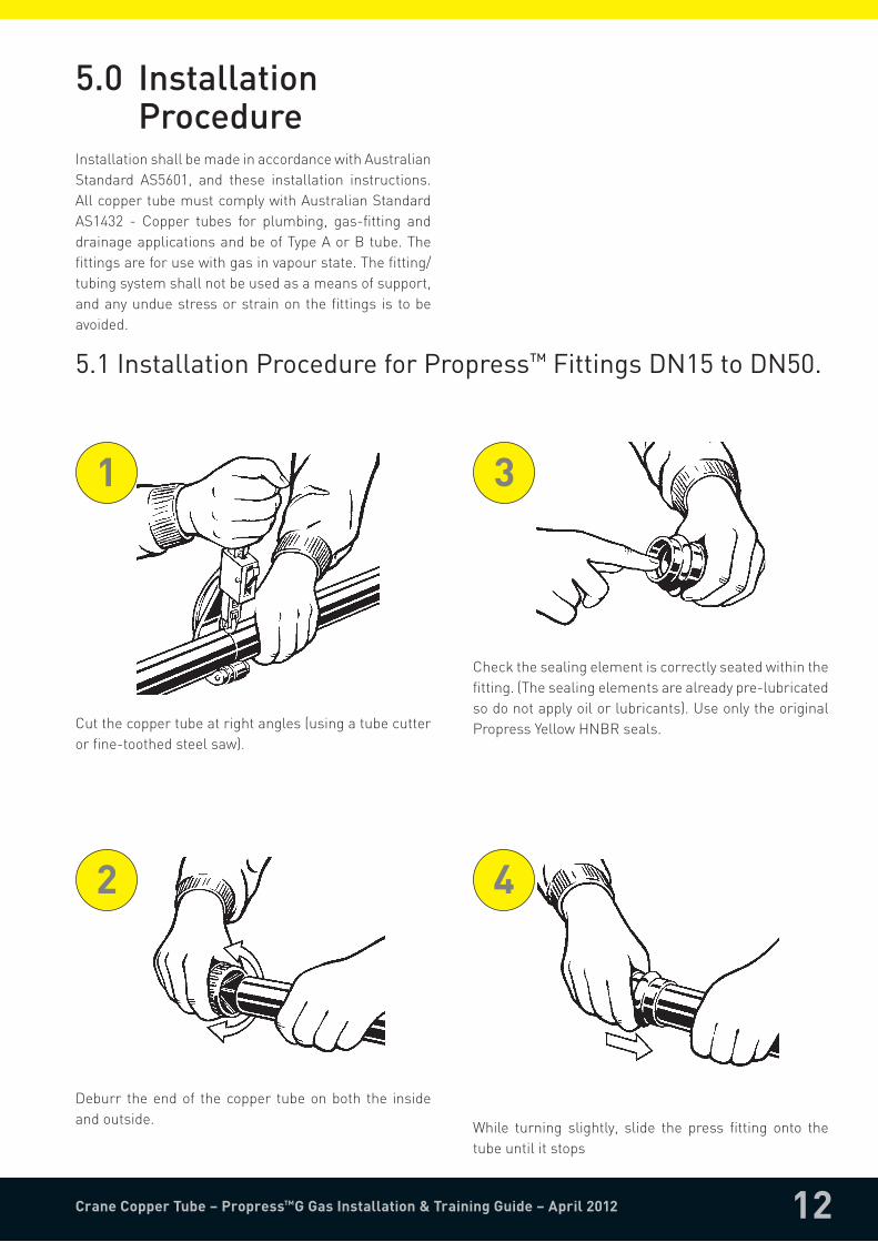
InstallationshallbemadeinaccordancewithAustralianStandard AS5601, and these installation instructions.AllcoppertubemustcomplywithAustralianStandardAS1432 - Copper tubes for plumbing, gas-fitting anddrainageapplicationsandbeofTypeAorBtube.Thefittingsareforusewithgasinvapourstate.Thefitting/tubingsystemshallnotbeusedasameansofsupport,andanyunduestressorstrainonthefittings is tobeavoided.
Cutthecoppertubeatrightangles(usingatubecutterorfine-toothedsteelsaw).
1
Deburr theendof thecopper tubeonboth the insideandoutside.
2
Checkthesealingelementiscorrectlyseatedwithinthefitting.(Thesealingelementsarealreadypre-lubricatedsodonotapplyoilorlubricants).UseonlytheoriginalPropressYellowHNBRseals.
3
While turning slightly, slide the press fitting onto thetubeuntilitstops
4
5.1InstallationProcedureforPropress™FittingsDN15toDN50.

13Crane Copper Tube – Propress™G Gas Installation & Training Guide – April 2012
Openthe jawsandplacethemontothefittingsothatthejawsareatrightanglestothefitting.
7
Checktheinsertiondepth.Startthepressingprocedurebyholdingthetriggeruntiltheramhascompletedthecycle.ChecktheindicationLEDsonthetooltoensurethepressinghasbeensuccessful.
8
Aftercompletingthepressingprocedure,openthejawsandwithdrawthepressingtool.
9
Insert thecorrectsize jaws into thepressingtoolandpushtheholdingpinuntilitlocksintoplace.
6
Marktheinsertiondepth.
5

14Crane Copper Tube – Propress™G Gas Installation & Training Guide – April 2012
Deburr the inside and outside of tubing to preventdamagetothesealingelement.
3
Keependoftubingaminimumof100mmawayfromthecontactareaofthevicetopreventpossibledamagetothetubinginthepressarea.
2
Cutcopper tubingat rightanglesusingdisplacementtypecutterorfine-toothedsteelsaw.
1
Illustration demonstrates proper fit of grip ring andsealingelement.UseonlyPropress™GYELLOWsealingelements.
6
Use only Propress™G fittings with YELLOW markings.Check seal and grip ring for correct fit. (The sealingelementsarealreadypre-lubricatedsodonotapplyoilorlubricants,usecleanwateronlyifnecessary).
5
Marktheinsertiondepth.
4
5.2 InstallationProcedureforPropress™XLFittings

15Crane Copper Tube – Propress™G Gas Installation & Training Guide – April 2012
Whileturningslightly,slidepressfittingontotubingtothemarkeddepth.Donotuseoilorlubricants.
7
With V2 ACTUATOR fitted into the tool, open the V2ACTUATORasshown.
10
Propress™ XL fitting connections must be performedwithPropress™XLRingsandV2ACTUATOR.SeeViegaOperator‘sManualforcorrecttoolinstructions.
8
PlaceV2ACTUATORontoXLRingandstartthepressingprocess.HoldthetriggeruntiltheActuatorhasengagedtheXLRing.KeephandsandforeignobjectsawayfromXLRingandV2ACTUATORduringpressingoperationtopreventinjuryorincompletepressing.
11
OpenXLRingandplaceatrightanglesonthefitting.XLRing must be engaged on the fitting bead. Checkinsertiondepth.
9
Oncompletionofpressing,releaseV2ACTUATORfromXLRingandthenremovetheXLRingfromthefitting.Remove sticker from fitting to indicate joint pressinghasbeencompleted.
12

Informationcontainedinthisbrochureisprovidedasaguideonly.CraneCopperTubedoesnotwarrantthattheinformationisaccurateorwithouterrorsoromissions.CraneCopperTubereservestherighttocorrectanyerrorsormisprints.Allinformationandproductdetailscontainedwithinthisdocumentareprovidedasaguideonly.Productuseshallbeconductedbyafullylicensedplumber/gasfitter.
Crane Copper TubeABN51008408151
ADivisionofCraneEnfieldMetalsPty.Limited
POBox319,PenrithNSW2751Phone:0247205350Fax:0247205390sales@cranecopper.com.auwww.cranecopper.com.auCRN9891.BMS0412
> Ultra fast installation.
> Permanent, strong, leak-free joints.
> No brazing, soldering or gluing required.
> Improves safety and efficiency.
> No need to drag gas bottles and hoses around the site.
> Approved for gas line installations Australia-wide.
> Cost effective for both low and high pressure installations.
> Can be used on type A and B copper tube.
> Proven track record with over 1 billion fittings in use worldwide.
> German precision engineered and manufactured fittings.
> Guaranteed for 25 years, with a design life of over 50 years.
> Superior pressure and temperature ratings .
> Can be used behind or in walls, direct sunlight and underground.
> Able to connect to existing copper lines.
> Cylindrical tube guide to protect sealing element during assembly.
> ‘Smart Connect’ leak detection feature to identify un-pressed fittings.
> Obvious pressing marks make it easy to see un-pressed fittings.
> One-piece fittings, ready for installation.
> Full flow joints (fittings maintain bore).
> Comprehensive range of fittings for both gas and water.
> One pressing tool can be used for both gas and water.
> Ease of use, yet tool is not cost effective for non professionals.