Embed Size (px)
Citation preview

66
Installation technology
5
Selection of an appropriate abstraction systemA water/sediment separation and water abstraction system must be suited to the hydrogeological conditions of the river channel and riverbank. The nature and depth of the river alluvium is a particular consideration. To aid the selection process, the appropriateness and advantages and disadvantages of each system are discussed here. For a complete description of various methods of sand-abstraction see Chapter 4.
Well-point and suction pumpThis is a suitable abstraction technology for areas where the river alluvium is deep, relatively stable and is ideally predominantly comprised of coarse sediment grains. The main criterion is an adequate depth of sediment. Well-points typically offer an effective and versatile option for most sand-abstraction situations.
Advantages• Low-cost—astraightforwardleveloftechnologywithonlyafewbasic
materials required for fabrication and installation.
In thIs chapter:
• Choiceofabstractiontechnology—considerations,whatworksandunderwhichconditionsitwillwork
• Methodsofabstractionequipmentinstallation;equipmentandskillsrequired
— Digging-in — Driving — Jetting• Theadvantagesanddisadvantagesofeachsystem
WfSR_05_Installation.indd 66 26/09/2007 15:26:29

67
5:InsTallaTIonTeChnology
• Lowmaintenance system–materials required formaintenanceandrepair are usually readily available, no expensive parts or specialist repair tools or equipment is required.
• Satisfactorydepthofinstallationeasilyachievable–systemusessimpleinstallation techniques to ensure a year round supply of water in the right conditions.
• Canbeusedinallseasons–whetherornottheriverisinflood.
• Multiplewell-points can be joined for high volume schemes and/or where permeability is low where the alluvium is fine grained.
• Safe–nounstablewellsidesliabletocollapseonusers,unliketraditionalopen wells.
• Easyontheenvironment–installationissub-surfaceandsystemrequireslittle infrastructure and no brushwood fences to protect it.
• Thesystemtypicallyyieldssafewatersuitableforhouseholduse.
Disadvantages• Requiresfabricationorpurchaseofabstractionorfabricationequip-
ment.
• Requiresasealedsystembetweenthewell-pointandthepump–airleaks in the connecting pipes or leaking pump seals render well-point systems inefficient or even inoperative.
• Equipmentcanbevulnerabletoflooddamage–althoughthesecurityof systems can be improved by anchoring the well-points to stakes, steel pipes or fence posts driven into the riverbed.
• Watermaycontainsignificanttracesofsiltwhenriverisinflood.
• Duringeffluentriverfloworwheretherearehighratesofabstraction,water in the river alluvium may become contaminated by the intrusion of salinesaltsfromtheriverbank.Mineralsaltswillaffectthepalatabilityof water and will contribute to encrustation around the well-point slots.
• Insomesituations,moreofteninperennial rivers, biofouling may occur within a well-point.
Infiltration gallery and collector well (sometimes known as a false well)The system draws water from a large area making it most suited for abstraction in river channels with shallow beds of alluvium, or where the alluvium is comprised of fine grained sediment.
The layout of an infiltration gallery can be adjusted to the nature of the
WfSR_05_Installation.indd 67 26/09/2007 15:26:29
68
WaTerfroMsanDrIvers
river. A single large diameter gallery across the river may be quite sufficient inwideslow-movingriverswhereasariverwhichisfastflowingwithahigh rate of sediment transport or a site on the outside of a river bend will require a number of short galleries, that might require anchoring to the riverbed with steel stakes.
Advantages• Nofabricationorcomplexinstallationequipmentisrequired.There
are proficient well diggers in many rural communities.
• Yearrounduse—whetherornottheriverisinflood.
• Very basic abstraction technology—water can be drawn from acollector well by a simple handpump or a by bucket on a rope.
• Providescleanwaterthatmaybeeasilydrawnfromaprotectedwell.
Disadvantages• Infiltrationgalleryscreeningrequirespurchaseorfabrication.
• Difficulttoinstalltoasufficientdepthtoensuresatisfactoryyearroundwater abstraction.
• Requiresasignificantamountofwork—diggingandliningacollectorwell on the riverbank and excavating a connecting trench for the galleries in the river alluvium.
• Equipmentcanbevulnerabletoflooddamage—althoughthiscanbeimproved by anchoring the infiltration pipes to stakes, steel pipes or fence posts driven into the riverbed.
• Difficultandcostlytoconstructinriverbanksthatarenotalluvialwhererock breaking techniques or compressors may be required.
CaissonA useful option in shallow, fine sediment where a pit can be excavated to theriverbedandastablefoundationsecuredfortheinstallation.Ideallyused in fine, stable river alluvium on a clay base or on bedrock where there is little transport of sediment through the channel.
Advantages• Simpletoconstruct—usesbasicwellconstructiontechnology,askill
many people in rural areas are conversant with.
• Suited to conditions of fine alluvium—due to a large screen areaavailable for infiltration.
• Particularlysuitedtolow-yieldingsmallsand rivers where installation canbe effected toa satisfactorydepth— intoor even through theriverbed.
WfSR_05_Installation.indd 68 26/09/2007 15:26:29

69
5:InsTallaTIonTeChnology
Disadvantages• Maybedifficulttoinstalltoasatisfactorydepth,particularlyinfluidized
sediment.
• Installationrequiresasolidfoundation.
• Whereacaissonissubmergedinsedimentthetopsurfacerequiresacover to prevent infill and clogging with silt.
• As the screen is typically formedbyno-fines concretewell-rings or courses of mortar free bricks, fine sediment is liable to penetrate a caisson that may then require de-silting.
Sand wellA larger structure than a caisson that extends from the base of the river channel to a height above the surface of the river sediment. Can be used as an offset sand well in an alluvial riverbank that has a high permeability and a good recharge to the well but may be used within river alluvium where suitable precautions are in place to prevent subsidence or in-filling with silt.
Advantages• Simpletoconstruct—usesshallowwellconstructiontechnology,a
skill with which many people in rural areas are conversant.
• Verybasicabstractiontechnology—watercanbedrawnbyasimplehandpump or a bucket on a rope.
• Aprotectedwellcanbeusedwhichwillyieldcleanwater.
• Suited to low-yielding small sand rivers where installation can be effectedtoasatisfactorydepth—intooreventhroughtheriverbed.
Disadvantages• Excavation in the riverbankor riverbedmaybedifficult toachievetoanadequatedepth.Particularlyinfluidizedsediment,de-wateringor well sinking techniques appropriate to unstable conditions may be required.
• Installationrequiresasolidfoundation.
• Withinriverchannelalluviumawellshaftcanbevulnerabletophysicalflooddamageandifnotadequatelysealed,tosiltation.
• Wheninstalledwithinariverchannel,systemcannotbeusedwhentheriverisinflood.
Figure 5.1 indicates the process of sand-abstraction site and equipment selection.
WfSR_05_Installation.indd 69 26/09/2007 15:26:29

70
WaTerfroMsanDrIvers
Figure 5.1. siteandequipmentselectionchart
Installation selection procedureThe following is a step by step selection procedure that can be used to identify a suitable abstraction technology with the correct equipment design criteria and dimensions.
1. Select the abstraction technology
1.1. Appraise the site in the following way:
• Determinethedepthofsediment.
• Analysesedimentparticlesize—assessfromfinetocoarse.
WfSR_05_Installation.indd 70 26/09/2007 15:26:33

71
5:InsTallaTIonTeChnology
• Approximatethegradientoftheriverchannelsedimentsurface.
• Determinetheextentoftheaquiferandcalculatethevolume.
• Observethenumberoftraditionalopensand wells and seek the advice of local people with regard to permanence of water.
1.2. Determine the system best suited to the site conditions (refer to foregoing information).
2. Select an appropriate screen (refer to Chapter 3, sediment classification). This will invariably be determined by the abstraction technology 1.2 above, but the following should be borne in mind:
2.1. Optimum style
• Anefficient screenwillnotbecomeblockedwithfine sedimentgrains–ineffecttheaperturesshouldbeself-cleaning,allowingevery particle that enters the screen to pass through and not become wedged. A slot tapering in the opposite direction to water flowisgenerallybetterthanaparallelsidedslot(seeFigure4.8,Chapter 4). Unfortunately it is virtually impossible to construct taper-sided slots or holes in homemade screens with apertures oflessthanapproximately5mm.Probablythebestthatcanbeachieved in homemade screens is to ensure that apertures are as clean as possible with little or no swarf to block the movement of particles.
• In theconstructionofhomemade screens longitudinal slotsaredifficult to fabricate in a pipe. Transverse slots are easier to cut but significantly weaken the pipe, which is likely to fracture between slot ends. Holes are easily drilled but particularly with smaller diameter holes it may be difficult to ensure a sufficiently large opensurfacearea.Photograph5.1showsarangeofwell-points andscreens.Photograph5.2showsafracturethatoccurredinahomemade transverse slotted well-point screen.
• Thescreensofcaissons and lined wells will typically be formed from no-fines concrete and will thus be random with no consistent aperturesizeand,dependingonthematerialsandconsistencyofmixtures may include large orifices or conversely may not have a sufficiently large screen area. Photograph5.3 showsnofinesconcrete well-rings of a type suitable for the construction of a collector well, caisson or sand well.
• Theaperturedimensionsofmortar freebrickworkmaynotbesufficiently narrow to preclude fine sediment.
WfSR_05_Installation.indd 71 26/09/2007 15:26:33

72
WaTerfroMsanDrIvers
photograph 5.1. selectionofwell-points
Commercial homemade
photograph 5.2. Well-pointfracturebetweentransverseslots
WfSR_05_Installation.indd 72 26/09/2007 15:26:34

73
5:InsTallaTIonTeChnology
2.2. Optimum aperture size
• Astandard recommendationbasedon traditionalwater supplyborehole design principles is that a screen slot size should belarge enough to allow 40 to 70% (nominally 60%) of sediment particlestopassthrough.Insituationswherethesedimentisofauniformgrade(mostlysinglesizeparticles)thelowerpercentageratesshouldbeobserved.Narrowslotstendtoblockmoreeasilyand satisfactory screens with small diameter holes are difficult to construct.Inrealityanacceptablescreencanusuallybedevelopedeven when a larger percentage of sediment grains pass through the apertures.Providedthesedimentisnotuniformlyfineaneffectivescreen will be formed but will take longer to develop as more fines will require extraction and consequently there may be greater wear tothepump.Ideallyanaturalfiltershouldbedevelopedinthesediment surrounding a well-point within 30 minutes of pumping. However, in exceptional cases, pumping in excess of this may be needed.
• Wheresedimentishomogenouslyfineascreenwithsmallaperturesmustbefabricated.Dependingonthesediment grading this can be undertaken with a 1.00, 0.75 or 0.5mm slotting saw or by drilling a pipe with 6mm holes and then wrapping the entire pipe in synthetic, non rotting geo-textile.
photograph 5.3. nofinesconcretewell-screen
WfSR_05_Installation.indd 73 26/09/2007 15:26:35
74
WaTerfroMsanDrIvers
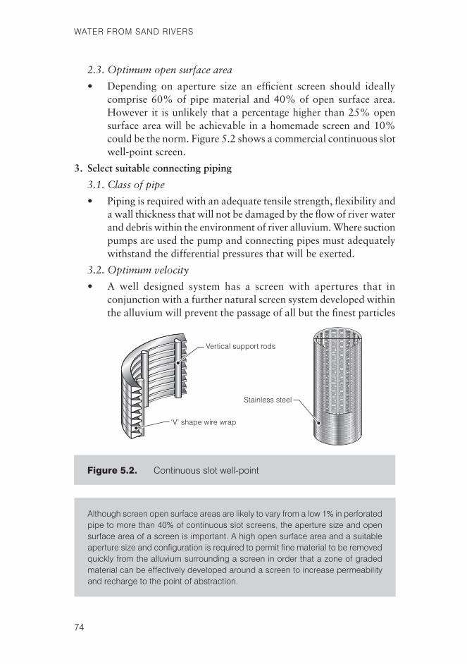
2.3. Optimum open surface area
• Depending on aperture size an efficient screen should ideallycomprise 60% of pipe material and 40% of open surface area. However it is unlikely that a percentage higher than 25% open surface area will be achievable in a homemade screen and 10% could be the norm. Figure 5.2 shows a commercial continuous slot well-point screen.
3. Select suitable connecting piping
3.1. Class of pipe
• Pipingisrequiredwithanadequatetensilestrength,flexibilityandawallthicknessthatwillnotbedamagedbytheflowofriverwaterand debris within the environment of river alluvium. Where suction pumps are used the pump and connecting pipes must adequately withstand the differential pressures that will be exerted.
3.2. Optimum velocity
• Awell designed system has a screenwith apertures that inconjunction with a further natural screen system developed within the alluvium will prevent the passage of all but the fi nest particles
Figure 5.2. Continuousslotwell-point
althoughscreenopensurfaceareasarelikelytovaryfromalow1%inperforatedpipetomorethan40%ofcontinuousslotscreens,theaperturesizeandopensurfaceareaofascreenisimportant.ahighopensurfaceareaandasuitableaperturesizeandconfigurationisrequiredtopermitfinematerialtoberemovedquicklyfromthealluviumsurroundingascreeninorderthatazoneofgradedmaterialcanbeeffectivelydevelopedaroundascreentoincrease permeabilityandrechargetothepointofabstraction.
WfSR_05_Installation.indd 74 26/09/2007 15:26:37

75
5:InsTallaTIonTeChnology
of sediment. In order to optimize such a filtration system andto prevent the further passage of sediment grains that do enter the system when it is developing or following disturbance of the alluvium during sediment transport, there is an optimum velocity ofwaterflowineachsectionoftheabstractionsystem.
Field experience indicates appropriate flow rates through a developed well-point screen system to be:
• Atthepointofabstraction0.03to0.07m/sec—thisisthevelocity of theflowofwater throughtheapertureareaofawell-point.Entrancevelocitiesintoawell-pointduringthedevelopmentstageof the natural filter when sediment particles are being displaced andrepositionedarelikelytobehigher.Lowentrancevelocitiesare preferable, ideally slow enough to achieve laminar flow inthe sediment. A low abstraction velocity also reduces the degree of incrustation that accumulates around screen apertures in groundwater that is high in mineral salts.
• Throughawell-pointandconnectingpipe,0.6to0.9m/sec—arelatively low velocity in this section prevents any further movement ofparticlesthathavebeendrawnintothepipework.Inmultiplewell-point systems a large diameter manifold to reduce the velocity offlowto0.3m/secwillfurtherensurethis.Thelayoutofamultiplewell-point system showing a central manifold with multiple off shootsisshowninPhotograph5.4.
• Through the pump, 1.25 to 1.5m/sec— this is the generallyrecommended maximum delivery velocity of a well-point system.
The entrance velocity of water into an infiltration gallery and ideally a sand well-screenshouldbe0.006m/sec.Thisslowrateofflowensuresthat in the creation of the filter in the sediment surrounding the gallery a minimum of fine sediment is drawn through the screen, which might create a blockage in the gallery pipe or in the well shaft.
Anexampleofthecalculationsoftheaperturesizeandpipediametersrequired in the correct design of a well-point system is detailed in Appendix 1.
3.3 Drawdown
• Byensuringthatasmuchaspossibleflowthroughsedimenttoascreen is laminar with abstraction rates not exceeding 1 to 1.5m³/hr
WfSR_05_Installation.indd 75 26/09/2007 15:26:37

76
WaTerfroMsanDrIvers
per well-point drawdown in coarse saturated sediment in practical termsisnotasignificantfactor.Duetothedifficultyofinstallinginfiltration galleries by hand to an adequate depth, drawdown ismore significantwith this system. Standard data collectionprocedures and formulae are available for calculating drawdown but again in practical terms, if the correct withdrawal velocities are observed problems seldom arise unless the water-level drops to the level of the upper apertures of the well-point or infiltration gallery.
photograph 5.4. Installationofamultiplewell-pointsystem
Inordertodevelopanefficientgradedzoneinthealluviumsurroundingascreen,apertures thatwill permit the removal of 60 to 75%of sedimentparticlesarerequiredand in finesedimentup to90%.The resultingnaturalscreenshouldextendforasmuchas300to600mmbeyondthescreensurface.Theincreasedporosityandhydraulicconductivityofthegradedmaterialassistintherechargeatthepointofabstraction,whichreducesthedrawdownandthepossibilityofaningressofairduringpumping.
Insufficientremovaloffinesedimentwillpreventanadequatedevelopmentofanaturalscreeninthealluvium.
excessive removal of coarse sediment grains will lead to large amounts ofsedimentdrawnintothedeliverysystem.
WfSR_05_Installation.indd 76 26/09/2007 15:26:39

77
5:InsTallaTIonTeChnology
Methods of installation This section examines the methods of equipment installation, equipment and skills required, and the pros and cons of each system.
• Digging-in
• Driving
• Jetting
Digging-inBy excavating, either by hand ormechanically, each system can bephysically dug into water yielding sediment.
•Well-points: a team equipped only with shovels is able to install a well-point into saturated sediment, however as with any digging, once fluidizedsedimentisreacheditisdifficulttodiganydeeperandunlessdug-in late in the dry season the water-level in the sediment is likely to dropsothatthescreenwillbeexposedbeforetheriverflowsagain.Aslight advantage can be gained by forcing a shovel as deep as possible intofluidizedsediment,thenrockingtheshovelbackwardsandforwardsand working in the well-point behind the shovel blade.
However, a largely untrained installation team with no sophisticated equipmentcanundertakedigging-in.Photograph5.5showsateamofinstallation technicians digging-in a well-point.
photograph 5.5. Digginginawell-point
E. M. Nyoni
WfSR_05_Installation.indd 77 26/09/2007 15:26:39

78
WaTerfroMsanDrIvers
• Infiltration-galleries and collector wells: as far as small-scale operators are concerned, digging-in is the most common solution toinstallinginfiltration-galleries.Inordertogainsufficientdepthwithout the use of de-watering pumps, mechanical excavators or shuttering, the manual installation of infiltration-galleries can only be carried out at the end of a dry-season, before the onset of rains.
• Caissons and sand wells: Digging-in is the onlyway inwhichcaissons and lined sand wells can be installed into river channel alluvium. When digging-in into unconsolidated alluvium it is a simple matter to place a well-ring at an appropriate point and to removethematerialfrominsidethering.Byremovingsedimentevenly, starting in the centre and moving out until material is removed from under the well-ring the ring will be lowered evenly intothealluvium,securingthesidesof thewellas itdrops.Byplacing a further ring on the top of the original ring the well lining is automatically placed and digging-in can continue safely in unstable material until water is reached. To assist the lowering of the lining the leading edge of the first ring can be bevelled to create a ‘cutting’ edge.
Digging-inisalsotheonlyoptionforbrickconstructedcaissons and sand well shafts located in a river channel. A frustum shaped excavation is required to a depth sufficient to ensure a satisfactory, stable foundation. The diameter of the base will need to be significantly wider than the outer diameter of the shaft and depending on the amount of fines and compaction of the sediment, the slope of the sides should be approximately 45° (the natural reclining angle of uncompacted sediment).
Onceagain,asitisnotpossibletoeffectivelyexcavatebyhandintowater saturated sanddue tofluidized sedimentwellingupwithin the well lining or caisson, digging-in should be carried out late in the dry season to ensure that a firm base is obtained and to prevent the well running dry as the season progresses. As a caisson does not extend to the surface of the alluvium the sides of a caisson excavation must be cleared away, at least to the natural reclining angle of the material, as the digging progresses.
Driving and jacking• Well-points—Wheresteelwell-points are used these can be easily
and quickly driven by a strong person with a steel sledge hammer.
WfSR_05_Installation.indd 78 26/09/2007 15:26:39

79
5:InsTallaTIonTeChnology
They can be either vertical or inclined to the full depth of the riverbedsediment.EvenwhereuPVC,ABSorplasticwell-points are used, these can also be driven to satisfactory depths of 3.00 to 5.00 metres if equipped with a sacrificial steel point and a steel driving tube.
To achieve depths in excess of 2.00m a driving tube in lengths of approximately 1.50m is required; alternatively a temporary platform or stepladder will enable 3.00m lengths to be installed. To reduce damage to the steel by hammering, a length of timber is best held or fitted to the top of the pipe. However, even with a wooden block there is likely to be significant damage to the tube, particularly where there are threads. The driving tube is removed from the sediment when the well-point has reached a satisfactory depth,leavingthewell-pointinplace.Photograph5.6showsawell-point being driven to a depth of 3.00m, with driving commencing from a step-ladder. Figure 5.3 indicates the protection that a block of wood can provide to a well-point driven with a steel hammer.
• Experience has shown that sediment can become compactedbetween the well-point tip and the driving tube making a fit so tight that when the driving tube is removed the well-point is also withdrawn! Two short wings attached to the well-point tip will
photograph 5.6. Drivinginawell-pointto3metres
WfSR_05_Installation.indd 79 26/09/2007 15:26:40

80
WaTerfroMsanDrIvers
reportsfromthemid-westoftheUsaindicatethat well-pointsfortube-wellwatersuppliescanbedrivenintogravelbedstodepthsof20metres.
Figure 5.3. Drivinginawell-pointshowingincorrectandcorrectmethods
photograph 5.7. InfiltrationgalleryandcollectorwellonBloodriver,southafrica
WfSR_05_Installation.indd 80 26/09/2007 15:26:41

81
5:InsTallaTIonTeChnology
preventthis.AdrawingofauPVCwell-pointwithsacrificialtipand anchoring wings is shown in Chapter 4, Figure 4.07.
• Infiltration galleries—Althoughbeyondthescopeofsmall-scaleoperatorstheBritishGeologicalSurvey(BGS)hasexperimentedwiththehorizontaljackingofinfiltrationpipesfromcollectorwellsbelow the bed of river channels. The system used was similar to the method above with a sacrificial tip and a jacking tube to push the tiphorizontallythroughtheformation.Inordertoundertakethisitis necessary to construct a collector well of a diameter not less than the combined length of the jacking pipes and the hydraulic jack, (some 3.00m). Although there is a distinct advantage in placing infiltration pipes below the riverbed to increase the functional time of a well in seasons of low rainfall, the level of technology and thesizeofthewellrequiredconstituteaconsiderabledrawback.Photograph5.7showsthetopofacollectorwellshaft,fromwhichinfiltration pipes radiate out under the riverbed.
Jetting• Well-points—jetting requires an independent source of water. A
motorizedcentrifugalpumpisrequiredtodischargewatereitherdirectly through a self-jetting well-point or from an open-ended pipe attached to a regular well-point. Well-screens can then be pushed(jetted) throughfluidizedsediment intothe lower levelsof sediment whilst it is in an induced quicksand condition. The system operates more effectively in saturated sediment than in dry material where the water is likely to be dissipated laterally. Thus jetting is best carried out when the river sediment is fully saturated, or in situations where overlying dry sediment has been removed to expose water saturated sediment.
Figure 5.4 shows a self-jettingwell-pointandPhotograph5.8theinstallation of a well-point by jetting. Finally Figure 5.5 indicates how the jetting process is effected as water is ejected from the open end of a pipe or a self-jettingwell-pointtoflowbacktothesurface.Itisimportanttomaintainflowaroundtheoutsideofthepipeorthe water ejected will simply be forced into the underlying sediment and the jetting pipe will cease to move. A simple well-point can be attached to a jetting pipe with a piece of low strength string. When a satisfactory depth has been reached the jetting process is stopped and material will collapse around the jetting pipe and well-point. The jetting pipe can then be withdrawn by breaking the string leaving the well-point in place.
WfSR_05_Installation.indd 81 26/09/2007 15:26:41

82
WaTerfroMsanDrIvers
This system of installation is more technically complex and is dependent on a portable centrifugal pump, source of water, materials and equipment that are often not readily available in disadvantagedareas.Byjetting when the alluvium is saturated to full depth there is an associated problem with not being able to sufficientlyburythewell-pointconnectingpipe.Insuchasituationthepipecouldbedamagedduringsubsequentriverflow.
• Infiltration-galleries— Some installation technicians reportinstalling infiltration pipes by jetting.Bymoving a jetting pipe slowly sideways through sediment rather than downward, the surface becomes fluidized to enable an infiltration pipe to beinserted. The practice is not as straight forward as downward jetting and requires experience and a greater degree of skill.
Figure 5.4. self-jettingwell-point
WfSR_05_Installation.indd 82 26/09/2007 15:26:42

83
5:InsTallaTIonTeChnology
photograph 5.8.Installingaself-jettingwell-point
Figure 5.5. Thejettingprocess
WfSR_05_Installation.indd 83 26/09/2007 15:26:43
84
WaTerfroMsanDrIvers
Chapter summaryThere is a range of screens and abstraction methods that are suitable for use in a number of differing situations. The correct system will depend on the nature of the river channel, the type and volume of the sediment, the site conditions and the requirements of the end users.
A well-point and suction pump scheme is a basic system that is easily installed and often provides a straightforward effective solution in conditionswherethereisdeepcoarsesediment.Eitheraninfiltrationgalleryand collector well system or a sand well are appropriate where sediment is fineorshallow.Otherabstractionsystemssuchascaissons and sand wells are best used where there is fine sediment and particularly in smaller river channels where it is possible to excavate deep into the riverbed.
The installation of well-points can be easily achieved by either digging, driving or jettingthemintodeepsediment.Theinstallationofhorizontalinfiltration-galleries is more difficult due to the difficulty of digging sufficiently deep in fluidized sediment. This difficultymay also occurwhen attempting to install collector wells, caissons or sand wells to an adequate depth.
In order to determine themost appropriatewater abstraction systemand installation method each system must be assessed against the river and sediment conditions, the materials available and the resources of the beneficiary community.
When the most suitable abstraction system has been decided an appropriate method of drawing water to the surface will be required. There are many methods of water lifting, of which not all are suitable for every system of sand-abstraction.
WfSR_05_Installation.indd 84 26/09/2007 15:26:43