Embed Size (px)
Citation preview

Electric Flow Boiler
INSTALLATION &
TECHNICAL MANUAL
If you require any further assistance:
Telephone: 01698 820533Fax: 01698 825697
E-mail: [email protected] visit our website www.electric-heatingcompany.co.uk

3GB-
INTRODUCTION
Please read and follow the installation and operating instructions carefully, to ensure the long life and reliable operation of this appliance. The Electric Heating Company may make minor changes when necessary in the appliance that will not be shown in the operating instructions, so long as the main features of the boiler remain the same.
All boilers come with a 24 month warranty that covers all defects originating from faulty materials and workmanship in the manufacture of the boilers. The warranty covers the replacement of any faulty parts and labour costs.
The warranty will not cover any damage to the boiler from poor or incorrect installation work. In addition the Warranty will not cover any call out charges that have not been organised by the Electric Heating Company Ltd. The warranty will not cover water leaks into the boiler. All plumbing joints must be checked.
A Magnetic Filter must be fitted to the Boiler in the return pipe-work and before the circulation pump. The Magnetic Filter must be cleaned at least annually. Failure to clean the Magnetic Filter may result in boiler/system failure. Warranty calls will not be covered where the above requirements have not been met. (Note: Some models of boilers may be supplied with a Magnetic Filter).
The ‘Slim Jim’ boiler is a low temperature boiler intended for unvented or vented central heating systems with forced circulation (protected according to legally binding directives). The boiler features:• automatic control,• low maintenance requirements,• internal temperature control,• a high current safety temperature cut-out.
The central heating installation in which the ‘Slim Jim’ boiler is being installed into, must be fitted with the following:
This appliance is not intended for use by persons (including children) with reduced physical, sensory or mental cap-abilities, or lack of experience and knowledge, unless they have been given supervision or instruction concerning use
of the appliance by a person responsible for their safety.
Children should be supervised to ensure that they do not play with the appliance.
CONTENTS:INTRODUCTION: 2INSTALLATION: 4ELECTRIC BOILER INTERNAL LAYOUT: 5TYPICAL HEATING SYSTEM SCHEMATIC: 8ELECTRICAL CONNECTIONS & CONTROLS: 9TYPICAL ELECTRICAL SYSTEM SCHEMATIC: 11CONNECTION OF EXTERNAL APPLIANCES: 12FRONT CONTROL PANEL OPERATION: 13FAULT FINDING: 15TECHNICAL SPECIFICATION: 15
4GB-
Vented Systems:• circulation pump,• pump valves,• F & E tank,• magnetic filter,• automatic by-pass, if required.
Unvented Systems:• circulation pump,• pump valves,• magnetic filter,• automatic by-pass, if required,• EHC sealed system kit,• Automatic air vent,• Twin Channel Heat Pack, if required.
Instructions and Building Regulations
This appliance must be fitted in accordance with the following instructions.
The Local Building Regulations.
The Building Regulations.
The Building Standards, (Scotland-consolidated) Regulations.
Local water bylaws.
British Standards code of practice.
BS EN 12828:2003Heating systems in buildings. Design for water-based heating systems
BS EN 12831:2003Heating systems in buildings. Method for calculation of the design heat load
BS EN 14336:2004Heating systems in buildings. Installation and commissioning of water based heating systems
BS 7671:2008Requirements for electrical installations. IEE Wiring Regulations. Seventeenth edition
BS EN 13831:2007Closed expansion vessels with built-in diaphragm for installation in water
C.O.S.H.H.Materials used in the manufacture of this appliance are non-hazardous and no special precautions are required when fitting or servicing this appliance.
PREPARATION
1. Load CheckA load check should be taken into consideration when installing high output kW boilers.
2. Boiler locationThe boiler must be fitted on a wall that will provide an adequate fixing, and should be fitted in a location that the boiler and pipe-work are not subject to frost and damp conditions.
3. Central heating (design & installation)Detailed recommendations are given in BS EN 12828:2003, BS 6700: 2006+A1: 2009 and CP 342-2:1974
Pipes forming part of the useful heating surface should be insulated to prevent any potential heat loss or frost damage (BS 6700:1997).
Drain valves should be fitted at the lowest point of the system pipe work in an accessible position.
Drain valves should be in accordance with BS 2879: 1980 and copper tube to BS EN 1057: 1996. is recommended.
LOCATIONThe boiler can be installed in almost any location within a do-mestic or commercial property, however consideration should be given to future maintenance. Never leave the boiler switched off if there is a danger of having temperatures below 0°C in the room where it is located.
We recommend that a minimum clearance of 400 mm should be allocated for: the removal of the front cover, adequate access to the boiler plumbing and the internal electrical connections. A 50 mm allowance should be made at either side of the boiler to allow free flow air into the boiler case and allow access to screws on the boiler case.
THE BOILER MUST BE INSTALLED IN THE UPRIGHT POSI-TION, FAILURE TO DO SO WILL INVALIDATE THE WARRAN-TY
5GB-
INSTALLATION
1. GeneralThe boiler must be installed by a professional plumber or heating engineer and must be connected to the public low voltage network by a competent person. We recommend this is installed by a 17th Edition certified Electrical Engineer.
The Electric Heating Company Ltd will not be held responsi-ble for faulty installations which are performed by un- quali-fied tradespersons.
2. Pipe ConnectionsAll Slim Jim Electric Boilers have a 22mm compression con-nection at the boiler’s flow and return pipes. Please note that the boilers are supplied with blank washers fitted for transit purposes. These must be removed before connections to pipe-work can be made.
The flow (red) and return (blue) are clearly marked on the external case and under no circumstances should these con-nections be reversed. Hot connections are not recommended at the boiler for future maintenance and boiler disconnection. Lock-shield valves are recommended.
3. Case RemovalIn order to take off the front cover, undo the fixing screws at the top and bottom of the unit and disconnect the wires from the Front Control Panel.
4. Isolation ValvesWe recommend that lock-shield isolation valves are fitted on the flow and return pipe-work. Such valves must be ‘full way’ and not ‘ball valves.’ The installation of ‘ball valves’ in the flow and return pipe-work will reduce the recommended flow rate through the boiler and promote premature boiler shutdown.
5. Auto air ventsAn auto air vent must be fitted to the external pipe work when installed in an unvented system.
6. Boiler SizingCalculate the ‘space heating’ requirements in accordance with BS EN 12831 and BS EN 14336. If the boiler is to heat the domestic hot water, an additional allowance of 3kW (10,239 Btu’s) should be made to the ‘space heating’ calculation.
7. InsulationWhere practical, and if at all possible, we recommend that all pipe-work be insulated, in particular the primary pipe-work with-in a boiler cupboard. This is to reduce heat loss and re-duce high cupboard temperatures from exposed pipe-work. (BS 6700: 2006+A1: 2009).
Allowance should be made for a radiator to be installed with-in the heating circuit and locked open. This will be located in the room that has the room thermostat installed.
8. System DesignAs the boilers are of low water content an open circuit must be achieved incorporating 2 metre’s of continuous 22mm pipe-work after boiler connections and before any zone valves.
We recommend the use of an automatic bypass within this circuit and set to the relevant settings to allow the minimum flow rates to pass through the boiler (8 l/min) when all radiator thermostats close. Allowance should be made for a minimum size radiator of 600mm x 600mm single convector or equal to 2500 Btu to be installed within the heating circuit and locked open. This will be located in the room that has the room ther-mostat installed. To comply with building regulations, Part L and Part J (in Scotland), room and cylinder thermostats must be fitted.
Note: We do not recommend the use of 8mm micro-bore pipe.
9. Water ConnectionsProvisions must be made for the replacement of water lost from the heating system (sealed systems). Reference should be made to BS EN 14336 for the method of filling and make up of water.
There must be no direct connection between the boilers cen-tral heating system and the main water supply. When mains water is required to fill the system directly, all local water bylaws must be observed, and any connection made must be disconnected after use.
10. FlushingWhen installing a new Boiler to existing radiators & pipe-work these items should be flushed before a new boiler is installed. New boiler installations also require to be flushed before boil-er start up. This is to ensure that no debris is trapped in the system as this may result in boiler failure.
11. System pressures All boilers are tested to 4.0 bar. The normal working pressure of the boiler should be set to approx 1.0 / 1.5 bar. All sealed systems should comply with the relevant building regulations and standards, including BS EN 13831 – Specification for Ex-pansion Vessels.
Please Note:It is imperative that a pre-installed magnetic filter is removed and cleaned at least annually. Failure to carry out this action will increase contamination of the boiler by system residue.
6GB-
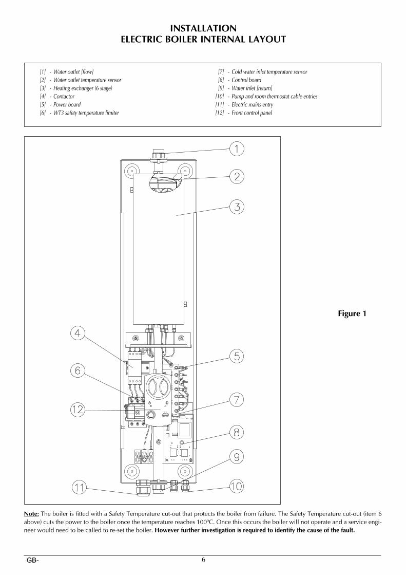
INSTALLATIONELECTRIC BOILER INTERNAL LAYOUT
Figure 1
[1] -Wateroutlet[flow] [2] -Wateroutlettemperaturesensor [3] - Heatingexchanger(6stage) [4] - Contactor [5] - Powerboard [6] -WT3safetytemperaturelimiter
1
2
3
4
5
6
7
8
9
1011
12
[7] - Coldwaterinlettemperaturesensor [8] - Controlboard [9] -Waterinlet[return] [10] - Pumpandroomthermostatcableentries [11] - Electricmainsentry [12] - Frontcontrolpanel
Note: The boiler is fitted with a Safety Temperature cut-out that protects the boiler from failure. The Safety Temperature cut-out (item 6 above) cuts the power to the boiler once the temperature reaches 1000C. Once this occurs the boiler will not operate and a service engi-neer would need to be called to re-set the boiler. However further investigation is required to identify the cause of the fault.
7GB-
INSTALLATION
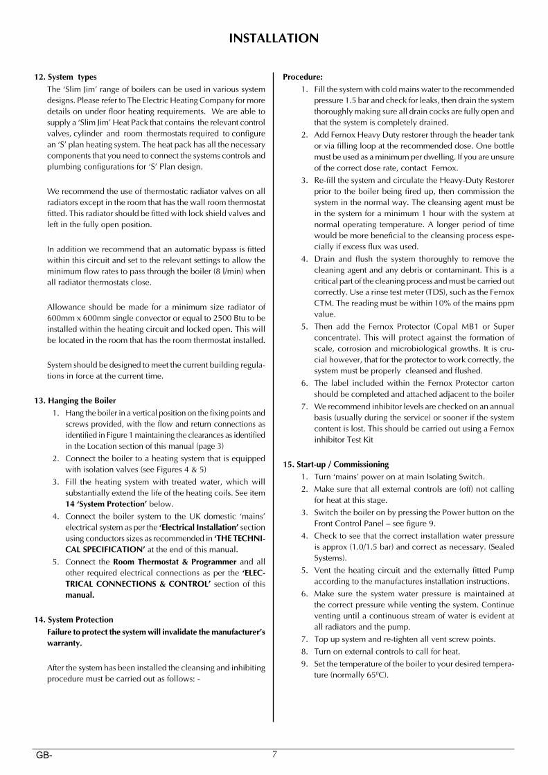
12. System types The ‘Slim Jim’ range of boilers can be used in various system
designs. Please refer to The Electric Heating Company for more details on under floor heating requirements. We are able to supply a ‘Slim Jim’ Heat Pack that contains the relevant control valves, cylinder and room thermostats required to configure an ‘S’ plan heating system. The heat pack has all the necessary components that you need to connect the systems controls and plumbing configurations for ‘S’ Plan design.
We recommend the use of thermostatic radiator valves on all radiators except in the room that has the wall room thermostat fitted. This radiator should be fitted with lock shield valves and left in the fully open position.
In addition we recommend that an automatic bypass is fitted within this circuit and set to the relevant settings to allow the minimum flow rates to pass through the boiler (8 l/min) when all radiator thermostats close.
Allowance should be made for a minimum size radiator of 600mm x 600mm single convector or equal to 2500 Btu to be installed within the heating circuit and locked open. This will be located in the room that has the room thermostat installed.
System should be designed to meet the current building regula-tions in force at the current time.
13. Hanging the Boiler1. Hang the boiler in a vertical position on the fixing points and
screws provided, with the flow and return connections as identified in Figure 1 maintaining the clearances as identified in the Location section of this manual (page 3)
2. Connect the boiler to a heating system that is equipped with isolation valves (see Figures 4 & 5)
3. Fill the heating system with treated water, which will substantially extend the life of the heating coils. See item 14 ‘System Protection’ below.
4. Connect the boiler system to the UK domestic ‘mains’ electrical system as per the ‘Electrical Installation’ section using conductors sizes as recommended in ‘THE TECHNI-CAL SPECIFICATION’ at the end of this manual.
5. Connect the Room Thermostat & Programmer and all other required electrical connections as per the ‘ELEC-TRICAL CONNECTIONS & CONTROL’ section of this manual.
14. System Protection Failure to protect the system will invalidate the manufacturer’s
warranty.
After the system has been installed the cleansing and inhibiting procedure must be carried out as follows: -
Procedure:1. Fill the system with cold mains water to the recommended
pressure 1.5 bar and check for leaks, then drain the system thoroughly making sure all drain cocks are fully open and that the system is completely drained.
2. Add Fernox Heavy Duty restorer through the header tank or via filling loop at the recommended dose. One bottle must be used as a minimum per dwelling. If you are unsure of the correct dose rate, contact Fernox.
3. Re-fill the system and circulate the Heavy-Duty Restorer prior to the boiler being fired up, then commission the system in the normal way. The cleansing agent must be in the system for a minimum 1 hour with the system at normal operating temperature. A longer period of time would be more beneficial to the cleansing process espe-cially if excess flux was used.
4. Drain and flush the system thoroughly to remove the cleaning agent and any debris or contaminant. This is a critical part of the cleaning process and must be carried out correctly. Use a rinse test meter (TDS), such as the Fernox CTM. The reading must be within 10% of the mains ppm value.
5. Then add the Fernox Protector (Copal MB1 or Super concentrate). This will protect against the formation of scale, corrosion and microbiological growths. It is cru-cial however, that for the protector to work correctly, the system must be properly cleansed and flushed.
6. The label included within the Fernox Protector carton should be completed and attached adjacent to the boiler
7. We recommend inhibitor levels are checked on an annual basis (usually during the service) or sooner if the system content is lost. This should be carried out using a Fernox inhibitor Test Kit
15. Start-up / Commissioning1. Turn ‘mains’ power on at main Isolating Switch.2. Make sure that all external controls are (off) not calling
for heat at this stage.3. Switch the boiler on by pressing the Power button on the
Front Control Panel – see figure 9.4. Check to see that the correct installation water pressure
is approx (1.0/1.5 bar) and correct as necessary. (Sealed Systems).
5. Vent the heating circuit and the externally fitted Pump according to the manufactures installation instructions.
6. Make sure the system water pressure is maintained at the correct pressure while venting the system. Continue venting until a continuous stream of water is evident at all radiators and the pump.
7. Top up system and re-tighten all vent screw points.8. Turn on external controls to call for heat.9. Set the temperature of the boiler to your desired tempera-
ture (normally 650C).
8GB-
INSTALLATION
Figure 3
Figure 2
9GB-
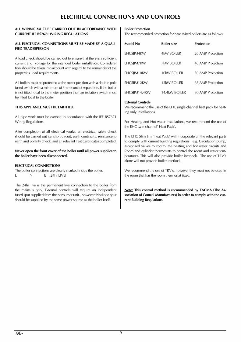
Boiler ProtectionThe recommended protection for hard wired boilers are as follows:
Model No Boiler size Protection
EHCSJIM4KW 4kW BOILER 20 AMP Protection
EHCSJIM7KW 7kW BOILER 40 AMP Protection
EHCSJIM10KW 10kW BOILER 50 AMP Protection
EHCSJIM12KW 12kW BOILER 63 AMP Protection
EHCSJIM14.4KW 14.4kW BOILER 80 AMP Protection
External ControlsWe recommend the use of the EHC single channel heat pack for heat-ing only installations.
For Heating and Hot water installations, we recommend the use of the EHC twin channel’ Heat Pack’.
The EHC Slim Jim ‘Heat Pack’ will incorporate all the relevant parts to comply with current building regulations e.g. Circulation pump, Motorized valves to control the heating and hot water circuits and Room and cylinder thermostats to control the room and water tem-peratures. This will also provide boiler interlock. The use of TRV’s alone will not provide boiler interlock.
We recommend the use of TRV’s, however they must not be used in the room that has the room thermostat fitted.
Note: This control method is recommended by TACMA (The As-sociation of Control Manufactures) in order to comply with the cur-rent Building Regulations.
ALL WIRING MUST BE CARRIED OUT IN ACCORDANCE WITH CURRENT IEE BS7671 WIRING REGULATIONS
ALL ELECTRICAL CONNECTIONS MUST BE MADE BY A QUALI-FIED TRADESPERSON
A load check should be carried out to ensure that there is a sufficient current and voltage for the intended boiler installation. Considera-tion should be taken into account with regard to the remainder of the properties load requirements.
All boilers must be protected at the meter position with a double pole fused switch with a minimum of 3mm contact separation. If the boiler is not fitted local to the meter position then an isolation switch must be fitted local to the boiler
THIS APPLIANCE MUST BE EARTHED.
All pipe-work must be earthed in accordance with the IEE BS7671 Wiring Regulations.
After completion of all electrical works, an electrical safety check should be carried out i.e. short circuit, earth continuity, resistance to earth and polarity check, and all relevant Test Certificates completed.
Never open the front cover of the boiler until all power supplies to the boiler have been disconnected.
ELECTRICAL CONNECTIONSThe boiler connections are clearly marked inside the boiler.L N E (24hr LIVE)
The 24hr live is the permanent live connection to the boiler from the mains supply. External controls will require an independent fused spur supplied from the consumer unit., however this fused spur should be supplied by the same power source as the boiler itself.
ELECTRICAL CONNECTIONS AND CONTROLS
10GB-
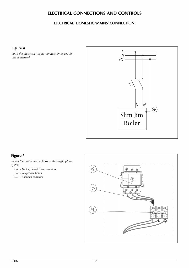
ELECTRICAL DOMESTIC ‘MAINS’ CONNECTION:
ELECTRICAL CONNECTIONS AND CONTROLS
Figure 4
Slim Jim
Boiler
howstheelectrical‘mains’connectiontoUKdo-mesticnetwork
L N
Figure 5showstheboilerconnectionsofthesinglephasesystem LNE - Neutral,Earth&Phaseconductors [6] - TemperatureLimiter [15] - Additionalconductor
11GB-
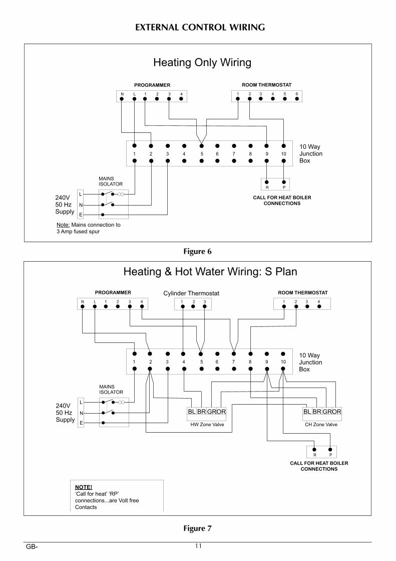
PROGRAMMER ROOM THERMOSTAT
CALL FOR HEAT BOILER
CONNECTIONS
Note: Mains connection to
3 Amp fused spur
PROGRAMMER ROOM THERMOSTAT
CALL FOR HEAT BOILER
CONNECTIONS
NOTE!
‘Call for heat’ ‘RP’
connections...are Volt free
Contacts
EXTERNAL CONTROL WIRING
Figure 6
Figure 7
12GB-
8
JP4
JP3
Pum
p m
ode
CTR
L en
ab.
CTRLN L
PumpRP
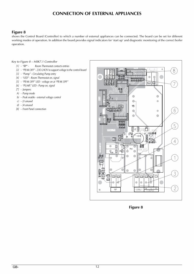
CONNECTION OF EXTERNAL APPLIANCES
Figure 8 shows the Control Board (Controller) to which a number of external appliances can be connected. The board can be set for different working modes of operation. In addition the board provides signal indicators for ‘start up’ and diagnostic monitoring of the correct boiler operation.
Figure 8
KeytoFigure8–MSK7.1Controller [1] - “RP“- RoomThermostatcontactsentries [2] - “PEAKOFF”-23O-24OVtosupportvoltagetothecontrolboard [3] - “Pump”-CirculatingPumpentry [4] - “LED”-RoomThermostaton,signal [5] - “PEAKOFF”LED-voltageonat“PEAKOFF” [6] - “PUMP,”LED-Pumpon,signal [7] - Jumpers: A) - Pumpmode b) - Peakenable-externalvoltagecontrol c) - J3unused d) - J4unused [8] - FrontPanelconnection
13GB-
CONNECTION OF EXTERNAL APPLIANCES
1. Room Thermostat A voltage free Room Thermostat should be connected to the boiler through the ‘RP’ [1] connections. When the connections are closed, a ‘call for heat’ has been requested to the boiler. Once Room Thermostat temperature setting has been reached the ‘call for heat’ will cease and the boiler will switch the heating off. The [4] led indicator on the Controller Board illuminates when the Room Thermostat ‘RP’ connections are closed.
2. Pump. The circulation pump shouldbe connected to connection block [3],
The pump is connected to the mains input voltage via a fuse (1A delayed 230V) that is situated on the control board. When the pump is operating the led indicator [6] is also illuminated.
3. Choosing pump mode. There are jumpers on the control board to control the operating mode of the pump [7]. Bridging the jumper described as “Pump mode” will operate the pump constantly, despite the status of the room thermostat. If it is not bridged, the pump will operate in an automatic cycle (i.e. when the room temperature reaches the set limit of the Room Thermostat, the pump will be turned off).
4. “PEAK OFF” voltage entries (optional). You can control the boiler (i.e. enable/disable its operation) by means of external voltage signal by bridging “PEAK enab” connection [7]. In this situation, the boiler will operate only when 230V AC is con-nected to “PEAK OFF” [2]. When this mode is enabled the led diode indicator [5] on the control board is illuminated.
Note: Connections of a Room Thermostat or other control device to the ‘RP’ connection point within the boiler must be ‘voltage free connections’, otherwise damage to the boiler will take place.
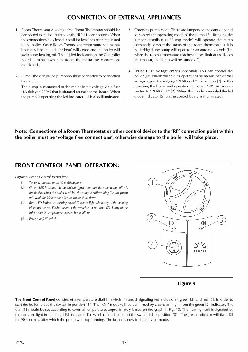
Figure 9
FRONT CONTROL PANEL OPERATION:
Figure9FrontControlPanelkey [1] - Temperaturedial(from30to60degrees) [2] - GreenLEDindicator-boileron/offsignal-constantlightwhentheboileris
on,flasheswhentheboilerisoffbutthepumpisstillworking(i.e.thepumpwillworkfor90secondsaftertheboilershutsdown)
[3] - RedLEDindicator-heatingsignalConstantlightwhenanyoftheheatingelementsareon.Flashes(eveniftheswitchisinposition‘0”),ifanyoftheinletoroutlettemperaturesensorshasafailure.
[4] - Power‘on/off’switch
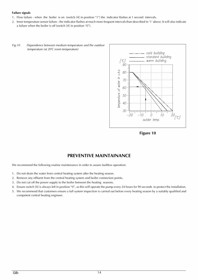
The Front Control Panel consists of a temperature dial[1], switch [4] and 2 signaling led indicators - green [2] and red [3]. In order to start the boiler, place the switch in position “1”. The “On” mode will be confirmed by a constant light from the green [2] indicator. The dial [1] should be set according to external temperature, approximately based on the graph in Fig. 10. The heating itself is signaled by the constant light from the red [3] indicator. To switch off the boiler, set the switch [4] in position “0”. The green indicator will flash [2] for 90 seconds, after which the pump will stop running. The boiler is now in the fully off mode.
14GB-
Failure signals1. Flow failure - when the boiler is on (switch [4] in position “1”) the indicator flashes at 1 second intervals.2. Inner temperature sensor failure - the indicator flashes at much more frequent intervals than described in ‘1’ above. It will also indicate
a failure when the boiler is off (switch [4] in position “0”).
Fig.10 Dependencebetweenmediumtemperatureandtheoutdoortemperature(at20°Croomtemperature)
PREVENTIVE MAINTAINANCE
We recommend the following routine maintenance in order to assure faultless operation:
1. Do not drain the water from central heating system after the heating season.2. Remove any effluent from the central heating system and boiler connection points.3. Do not cut off the power supply to the boiler between the heating seasons.4. Ensure switch [4] is always left in position “0”, as this will operate the pump every 24 hours for 90 seconds to protect the installation.5. We recommend that customers ensure a full system inspection is carried out before every heating season by a suitably qualified and
competent central heating engineer.
Figure 10
15GB-
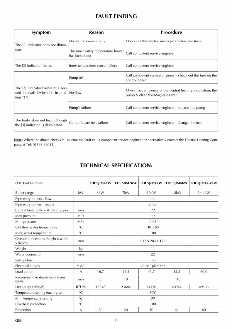
FAULT FINDING
Symptom Reason Procedure
The [2] indicator does not illumi-nate
No mains power supply Check out the electric mains parameters and fuses
The inner safety temperature limiter has locked out
Call competent service engineer
The [3] indicator flashes Inner temperature sensor failure Call competent service engineer
The [3] indicator flashes at 1 sec-ond intervals (switch [4] in posi-tion “1”)
Pump offCall competent service engineer - check out the fuse on the control board
No flowCheck out efficiency of the central heating installation, the pump & clean the Magnetic Filter
Pump’s failure Call competent service engineer - replace the pump
The boiler does not heat although the [3] indicator is illuminated
Control board fuse failure Call competent service engineer - change the fuse
Note: Where the above checks fail to cure the fault call a competent service engineer or alternatively contact the Electric Heating Com-pany at Tel: 01698 82053.
TECHNICAL SPECIFICATION:
EHC Part Number: EHCSJIM4KW EHCSJIM7KW EHCSJIM4KW EHCSJIM4KW EHCSJIM14.4KW
Boiler range kW 4kW 7kW 10kW 12kW 14.4kW
Pipe entry boilers - flow top
Pipe entry boilers - return bottom
Central heating flow & return pipes mm 22
Max pressure MPa 0,3
Min. pressure MPa 0,05
Out flow water temperature 0C 30 ÷ 80
Max. water temperature 0C 100
Overall dimensions (height x width x depth) mm 912 x 203 x 172
Weight kg 11
Water connection mm 22
Safety class IP22
Electrical supply V AC 230V 1ph 50Hz
Load current A 16,7 29,2 41,7 52,2 60,0
Recommended diameter of main cable mm 6 10 16
Heat output (Btu/h) BTU/h 13648 23884 34120 40944 49133
Temperature setting (factory set) 0C 80°C
Min. temperature setting 0C 30
Overheat protection 0C 100
Protection A 20 40 50 63 80

Electric Heating Company LtdUnit 40, Block 5
Third RoadBlantyre Industrial Estate
BlantyreGlasgow
G72 0UP
Tel: 01698 820533 Fax: 01698 825697
www.electric-heatingcompany.co.uk