Embed Size (px)
Citation preview
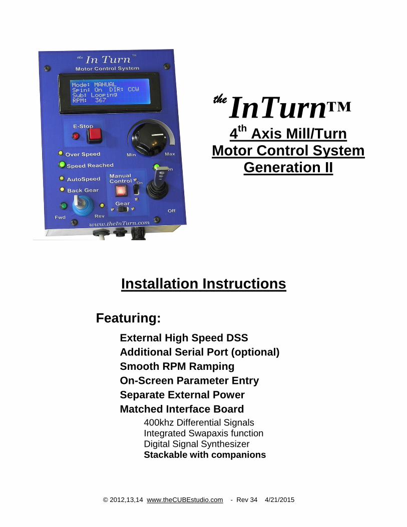
InTurn™ 4
th Axis Mill/Turn
Motor Control System Generation II
Installation Instructions
Featuring:
External High Speed DSS
Additional Serial Port (optional)
Smooth RPM Ramping
On-Screen Parameter Entry
Separate External Power
Matched Interface Board
400khz Differential Signals Integrated Swapaxis function Digital Signal Synthesizer Stackable with companions
© 2012,13,14 www.theCUBEstudio.com - Rev 34 4/21/2015
™
the
2
Contents
Introduction: ............................................................................................................................................................ 4
MACH3 new PROFILE creation: ........................................................................................................................... 5
Download, UnZIP and Copy Files: ......................................................................................................................... 6
MACH3 Brain Programs ........................................................................................................................................ 7
Drivers..................................................................................................................................................................... 8
Install the Arduino Drivers (only if this is a new install) ................................................................................... 8
Configuring MACH3 .............................................................................................................................................. 9
Tell MACH3 to use the new screens: ................................................................................................................. 9
Tell MACH3 to use the new Brain Programs: .................................................................................................... 9
Tell MACH to use the included Macro Pump. ................................................................................................. 10
Set up ModBus in MACH: ................................................................................................................................... 11
ModBus notes: .................................................................................................................................................. 11
Enter ModBus Parameters ................................................................................................................................ 12
Test ModBus Communication with the InTurn™ Controller: ........................................................................ 13
Input/Output ASSIGNMENTS ............................................................................................................................. 15
Hardware and Wiring ............................................................................................................................................ 18
4th axis HOME INDEX SENSOR connection: ................................................................................................ 18
Controller Combo Board Functions .................................................................................................................. 18
PRE-WIRED CONNECTIONS: InTurn™ controller to combo board ........................................................... 19
Connect wires to Your Servo Drive: ................................................................................................................. 19
Connect wires to Your Break Out Board: ......................................................................................................... 19
‘A’ Axis STEP (color choice and Pin number choice by User) ................................................................... 19
‘A’ Axis DIRection ....................................................................................................................................... 19
Connect wires to a 5 Volt DC power supply. ................................................................................................... 19
5V Power (Color choice by user – Red is suggested) ................................................................................... 20
POWER GROUND (color choice by user – Black is Suggested) ................................................................ 20
Adding your system Parameters into the InTurn™ Controller ............................................................................. 21
AutoConfigure .................................................................................................................................................. 21
* Maximum motor RPM – this is the motor itself and not the 4th
axis spindle. ........................................... 21
* Encoder resolution. This need to be in ‘counts’ or ‘steps’ and not ‘lines’ ................................................ 21
* Main Drive Ratio – this is the belt ration without double reduction (back gear). ..................................... 21
* Back Gear Ratio – borrowing the term from lathes, ‘Back Gear is the extra ............................................ 21
*Drive Multiplier – many drives have step multipliers or ‘electronic gearing’. .......................................... 21
Addendum A ........................................................................................................................................................ 23
Release Notes .................................................................................................................................................... 23
3
Addendum B ......................................................................................................................................................... 26
Listing of Provided Macros .............................................................................................................................. 26
Addendum C ......................................................................................................................................................... 27
Definitions......................................................................................................................................................... 27
CNC Terminology: ....................................................................................................................................... 27
Computer Terminology:................................................................................................................................ 27
InTurn™ Terminology: ................................................................................................................................ 28
MACH Terminology:.................................................................................................................................... 29
Servo Motor Terminology: ........................................................................................................................... 30
Signals and Hardware Terminology: ............................................................................................................ 30
4
Introduction: At the end of this document is an addendum that provides both the definition and a short description of the long list of ‘keywords’ used in CNC and also in General Digital Communications. It is not necessary to understand all of the terms used in this document since each task is presented with the specific information you will need to provide and also the specific points where you need to enter that information. For those who would like a better understanding of the underlying processes provided by the device they are installing as well as the device they are installing it on, each technical term that is blue in the text will have a corresponding definition and brief description in the addendum. Often, only this little bit of extra information can make a mysterious topic far more comprehendible.
The InTurn™ 4th axis Motor Control System is designed specifically to provide Mill/Turn capabilities for Mach3 and Mach4 CNC control Software for any CNC mill. Mill/Turn is a capability of high-end Machining Centers that have a starting price tag around US$100,000, so it is a very significant achievement to bring some of those capabilities to an existing benchtop of full size CNC mill for under US$5,000. Mill/Turn requires the 4th axis to have the capability to spin continuously at high speed with a significant amount of power over a wide range of speeds, and ALSO have the ability to stop spinning and return to the conventional indexing process. To be useful as a CNC add-on capability, all of this has to be controllable by the CNC system itself with minimal or no intervention by an operator. While MACH software provides for indexing on a rotary axis, it has no ability to spin that axis continuously. The InTurn™ 4th axis Motor Control System adds that basic capability and a lot more, all controllable both from custom on-screen controls and also via macros embedded in the G-code for a fully automated CNC process. So let’s get on with the Installation! Note: In the text, where the name of a parameter will vary from one system to another, or from one version to another, the variable portion is represented by ‘placeholders’ using ‘xx’ to represent numbers and square brackets around a descriptive word like ‘[date]’ to represent the variable part of a filename or folder name. The actual name will contain the number or date, for example ‘COM10’ or ‘InTurn™Parameter041215.brn’
5
“Interviews are good if you want to be an actor because they raise your profile.” - Jack Gleeson
MACH3 new PROFILE creation:
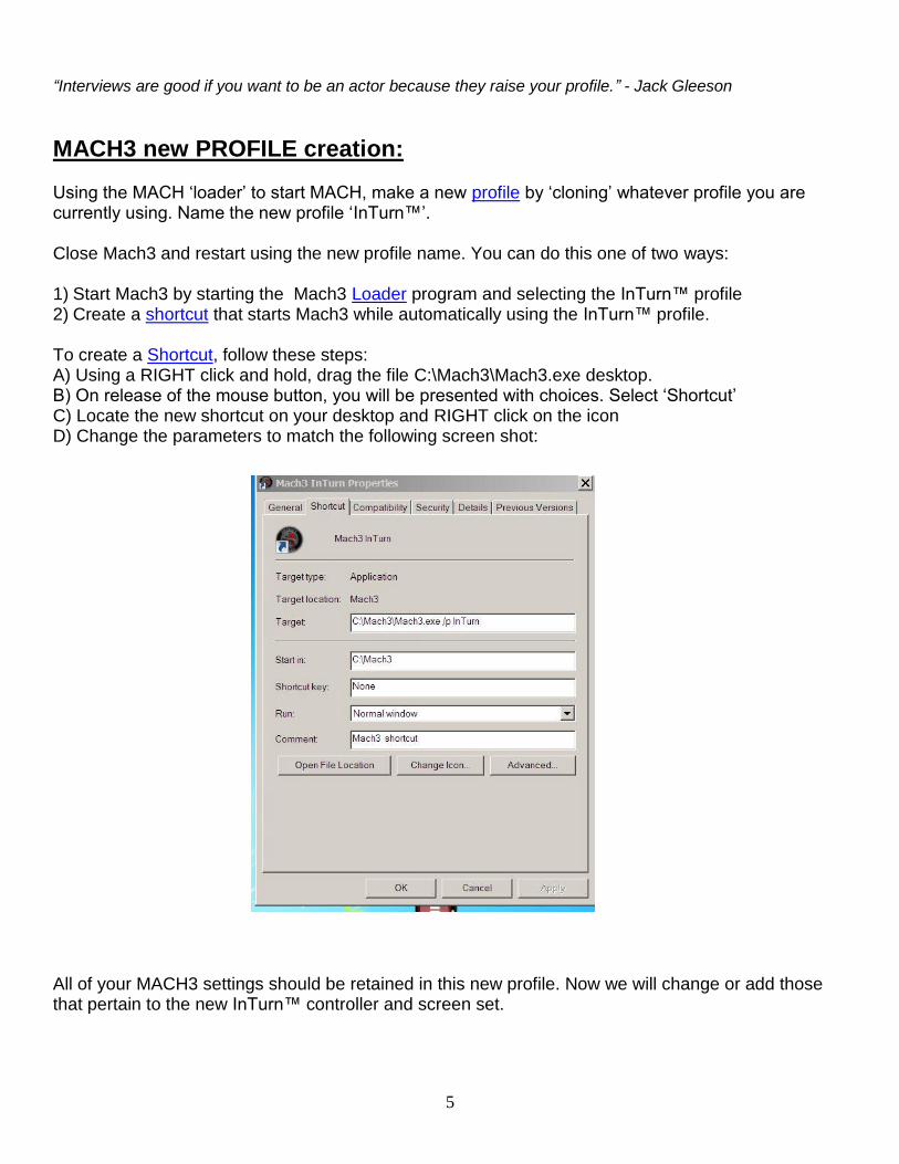
Using the MACH ‘loader’ to start MACH, make a new profile by ‘cloning’ whatever profile you are currently using. Name the new profile ‘InTurn™’. Close Mach3 and restart using the new profile name. You can do this one of two ways: 1) Start Mach3 by starting the Mach3 Loader program and selecting the InTurn™ profile 2) Create a shortcut that starts Mach3 while automatically using the InTurn™ profile. To create a Shortcut, follow these steps: A) Using a RIGHT click and hold, drag the file C:\Mach3\Mach3.exe desktop. B) On release of the mouse button, you will be presented with choices. Select ‘Shortcut’ C) Locate the new shortcut on your desktop and RIGHT click on the icon D) Change the parameters to match the following screen shot: All of your MACH3 settings should be retained in this new profile. Now we will change or add those that pertain to the new InTurn™ controller and screen set.
6
Download, UnZIP and Copy Files:
Files are obtained by downloading. Links will be provided via e-mail for new controllers, updates or upgrades. Using the provided link, download the zip file and move it into C:\ and then unzip the file. The files will be unzipped into folders that match the corresponding MACH folder name except that the names have the prefix ‘InTurn_’ added. The InTurn files can be safely stored in these folders since MACH does not recognize the folder names and therefore will not overwrite them. Simply copy the entire contents of the unzipped ‘InTurn_[name]’ folders into the matching Mach folders. For example, copy all of the files in “InTurn_MillBitmaps” into the \Mach3\Bitmaps\MillBitmaps folder. Do the same with all of the new InTurn folders that appear after unzipping the file.
In the end, you need to have: New macros from “InTurn_Macros” into the directory \Mach3\macros\InTurn
Note: Mach has a special macro named ‘HiddenScript.m1s which contains ALL of the macros associated with the screen controls. This is a reserved name (cannot be changed) so there is no way to know the version of the macro or what screen it goes with. For this reason, the InTurn™ version is named ‘HiddenScript[date].m1s’. Do not change the name of this file. Instead, copy the file, for example ‘HiddenScript012514.m1s’ into the Mach3\macros\InTurn folder and then change the name of that file by removing the date. Note: Some versions of MACH3 will unexpectedly overwrite the entire macro folder without warning or notice. This will stop the InTurn™ from functioning. The remedy is to copy the macros from your backup; “InTurn_Macros’ into the \Mach3\macros\InTurn folder again and then remove the date from the name of ‘HiddenScript[date].m1s”.
7
MACH3 Brain Programs
“Why, I outta BRAIN ya” – the three Stooges Copy the following from InTurn_Brains into C:\Mach3\Brains InTurn4thAxis[date].brn InTurnE-stop[date].brn InTurnAxisFraction[date].brn InTurnParam[date].brn Note: for these brain programs, the date can be left in as part of the file name. Later, you will activate the brains using the entire name including the date.
“Everyone can do simple things to make a difference, and every little bit really does count.” - Stella McCartney
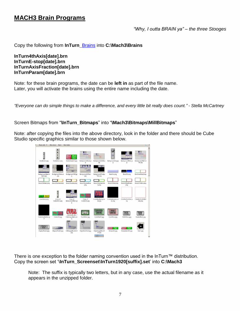
Screen Bitmaps from “\InTurn_Bitmaps” into “\Mach3\Bitmaps\MillBitmaps”
Note: after copying the files into the above directory, look in the folder and there should be Cube Studio specific graphics similar to those shown below.
There is one exception to the folder naming convention used in the InTurn™ distribution. Copy the screen set ‘\InTurn_Screenset\InTurn1920[suffix].set’ into C:\Mach3
Note: The suffix is typically two letters, but in any case, use the actual filename as it appears in the unzipped folder.
8
Drivers
“A careful driver is one who honks his horn when he goes through a red light.” - Henry Morgan A folder named ‘InTurn_Drivers’ appears after unzipping; Install the Arduino Drivers (only if this is a new install)
Plug in the USB cable to any USB port on your computer. Windows should complain about the new USB device. Tell windows to look in the folder: C:\InTurnMotorControllerDist2015-xx\InTurn_Drivers
Note: Bolded numbers are year and rev and may be different than shown. Windows will find and install the drivers then be happy with the new USB device. To determine which COM number the driver created, use the following steps Make sure MACH3 is NOT running. Power OFF the InTurn™ Controller. Power ON the InTurn™ Controller. On the menu bar at the lower left of the WINDOWS screen, click the following sequence: Start->Control Panel -> System -> Hardware (tab) -> Device Manager (button) -> Ports (COM & LPT) There should be a ‘Communications Port’ Identified as Arduino Mega and a COM# after it. Write the port number of your InTurn™ Controller below. You will need it later. ___________ InTurn™ Communication Port Number
9
Configuring MACH3 “I've always been bossy.” - Shirley Temple
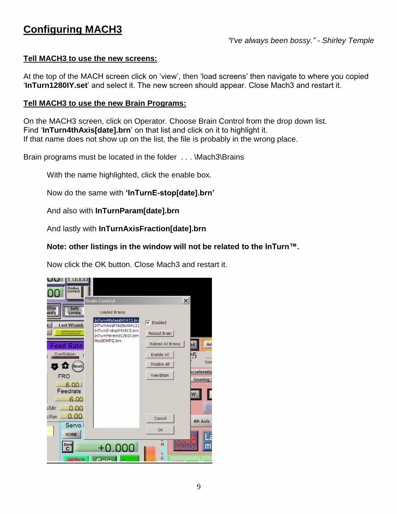
Tell MACH3 to use the new screens: At the top of the MACH screen click on ‘view’, then ‘load screens’ then navigate to where you copied ‘InTurn1280IY.set’ and select it. The new screen should appear. Close Mach3 and restart it. Tell MACH3 to use the new Brain Programs: On the MACH3 screen, click on Operator. Choose Brain Control from the drop down list. Find ‘InTurn4thAxis[date].brn’ on that list and click on it to highlight it. If that name does not show up on the list, the file is probably in the wrong place. Brain programs must be located in the folder . . . \Mach3\Brains
With the name highlighted, click the enable box. Now do the same with ‘InTurnE-stop[date].brn’ And also with InTurnParam[date].brn And lastly with InTurnAxisFraction[date].brn Note: other listings in the window will not be related to the InTurn™. Now click the OK button. Close Mach3 and restart it.
10
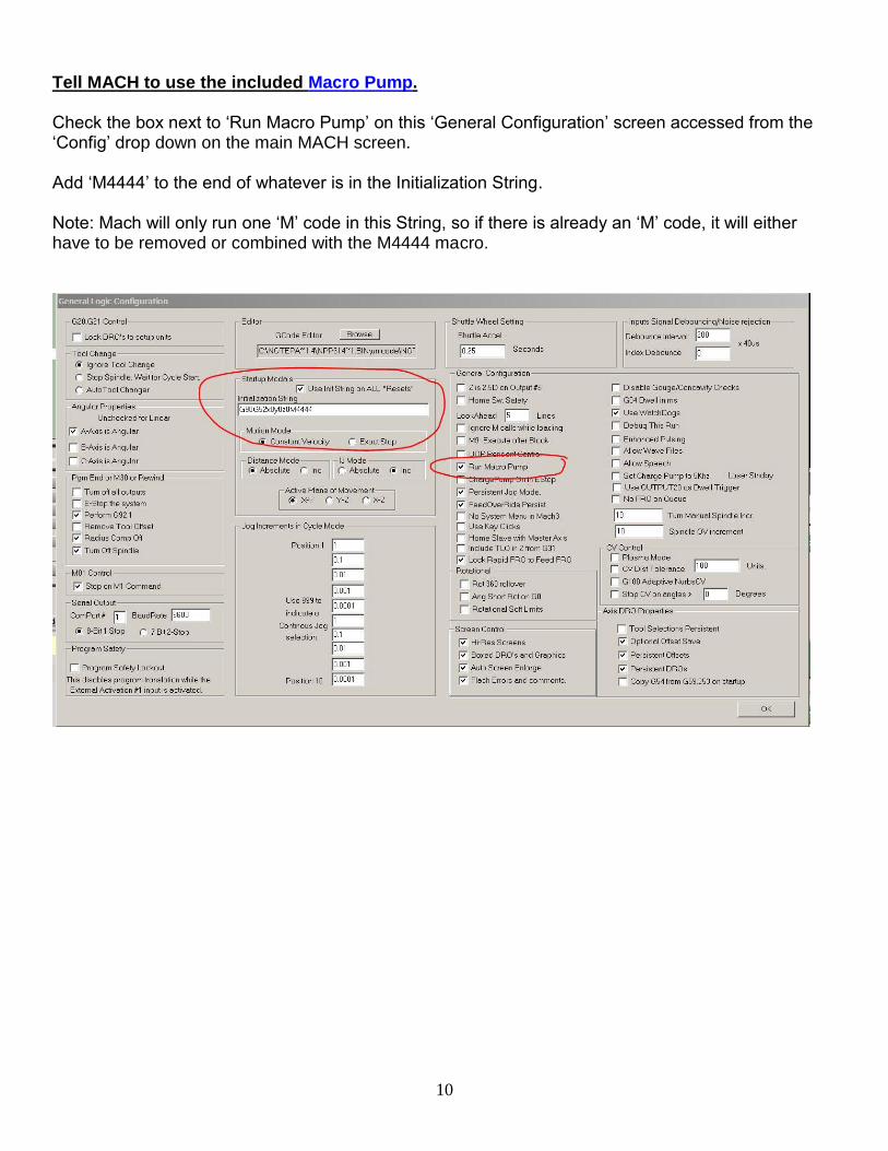
Tell MACH to use the included Macro Pump. Check the box next to ‘Run Macro Pump’ on this ‘General Configuration’ screen accessed from the ‘Config’ drop down on the main MACH screen. Add ‘M4444’ to the end of whatever is in the Initialization String. Note: Mach will only run one ‘M’ code in this String, so if there is already an ‘M’ code, it will either have to be removed or combined with the M4444 macro.
11
Set up ModBus in MACH:
“Setting goals is the first step in turning the invisible into the visible.” - Tony Robbins
First, it is helpful to understand what ‘ModBus’ is and also what it is not.
It is not something extra that you have to buy and install on your computer.
‘ModBus’ refers to an interface standard just like ‘serial’, ‘parallel’, ‘USB’, ‘Ethernet’, etc.
The physical connection varies, and in this case, the connection is made using any normal USB port on your computer.
However, ‘ModBus’ is not a physical thing. It is a set of rules. When two devices follow the same rules, they can communicate and send information back and forth.
The speed and capacity of a ‘ModBus’ setup depends on what kind of hardware it is running on and what kind of ‘topology’ (serial, Ethernet, etc.) is being used.
Second, you just need to know the steps to take to set up your ModBus. ModBus notes: MACH3 ModBus starts automatically when MACH3 starts and it talks to the controller thru COMxx. While xx can be any number, it must be the SAME for both the controller and ModBus, and that will only happen if the correct sequence is followed in the startup. In the explanation below, COM8 is used as an example for clarity, but remember that your number may be different. It is important to recognize that these are not actual physical ports, but are ‘virtual’ ports created on-the-fly and reside in the computer’s memory ‘emulating’ a real port. IMPORTANT: While plugged into the USB port, the controller will automatically create the NEXT AVAILABLE COMxx in the computer EACH time it is powered on, so the COM number that is created depends on the conditions AT THE TIME the controller is powered on. In this example, COM8 is the next available so the Controller creates COM8. There is no physical COM8, but the ‘fake’ COM8 behaves as if it was real. In the configuration, MACH was told to use COM8 for ModBus communication, so if MACH3 is started BEFORE the controller, it will still open ‘COM8’ even though there is no controller present. If the controller is started AFTER MACH is already running, when the controller scans for the next available COMxx it will find COM8 is already ‘IN USE’ and will, therefore, skip past it and will create COM9. If this happens, MACH and the Controller will be on different ports, so . . no talkie.
12
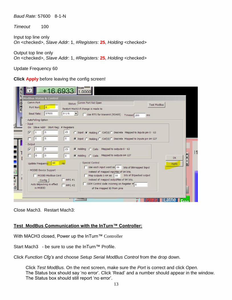
Enter ModBus Parameters
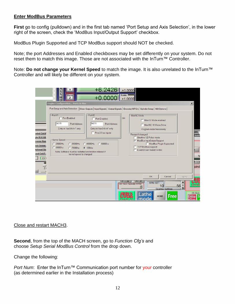
First go to config (pulldown) and in the first tab named ‘Port Setup and Axis Selection’, in the lower right of the screen, check the ‘ModBus Input/Output Support’ checkbox. ModBus Plugin Supported and TCP ModBus support should NOT be checked. Note; the port Addresses and Enabled checkboxes may be set differently on your system. Do not reset them to match this image. Those are not associated with the InTurn™ Controller. Note: Do not change your Kernel Speed to match the image. It is also unrelated to the InTurn™ Controller and will likely be different on your system.
Close and restart MACH3. Second, from the top of the MACH screen, go to Function Cfg’s and choose Setup Serial ModBus Control from the drop down. Change the following: Port Num: Enter the InTurn™ Communication port number for your controller (as determined earlier in the Installation process)
13
Baud Rate: 57600 8-1-N Timeout 100 Input top line only On <checked>, Slave Addr: 1, #Registers: 25, Holding <checked> Output top line only On <checked>, Slave Addr: 1, #Registers: 25, Holding <checked> Update Frequency 60 Click Apply before leaving the config screen!
Close Mach3. Restart Mach3:
Test ModBus Communication with the InTurn™ Controller: With MACH3 closed, Power up the InTurn™ Controller
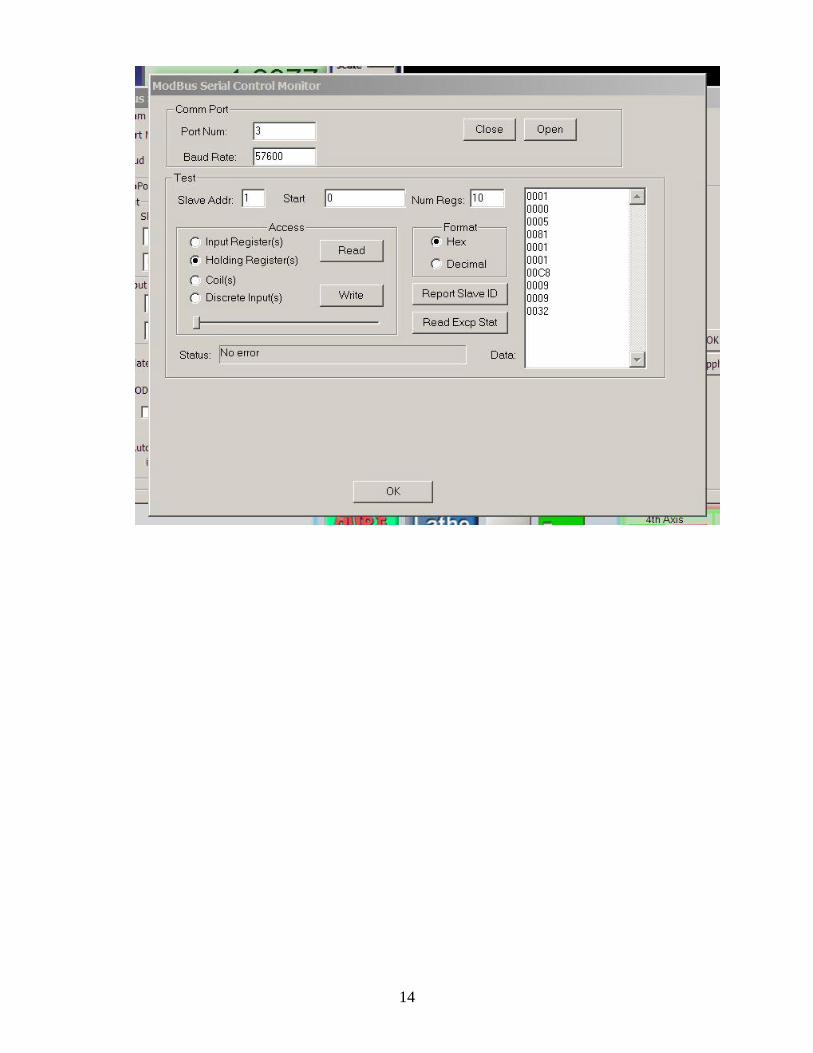
Start Mach3 - be sure to use the InTurn™ Profile. Click Function Cfg’s and choose Setup Serial ModBus Control from the drop down.
Click Test ModBus. On the next screen, make sure the Port is correct and click Open. The Status box should say ‘no error’. Click ‘Read’ and a number should appear in the window. The Status box should still report ‘no error’.
14
15
Input/Output ASSIGNMENTS
“Management is getting people together to figure out how to transform inputs into outputs.”
- Clayton Christensen
Note: The actual pin numbers and I/O # will vary from one system to another. Note: The physical pins are defined as either output or input. These are shown at the bottom of the MACH configuration screens for Input and Output respectively. If there is a conflict (an I/O # described below is already in use), then simply select any available OUTPUT# and change the configuration accordingly. Fill in the pin number that you use.
Pin OUTPUT# I/O Active Function
_____ OUTPUT#18 Out High Spindle lock solenoid
The following do not apply to all drives:
____ OUTPUT#19 Out High Servo Enable (for drives with this feature)
_____ OUTPUT#17 Out High PC (Proportional Control, industrial drives only)
_____ OUTPUT#12 Out High TL1(Torque Limit, industrial drives only)
_____ OUTPUT#20 Out Low Surrogate E-stop signal
Notes on the OUTPUT#:
*You will want to use the Enable/Disable feature of your servo drive (if it has this feature). *Some drives output an alarm (E-stop) when they are disabled and some do not.
*If your drive can be disabled, you do not want your CNC to E-stop every time you disable the drive, so this surrogate signal is provided to splice into the normal E-stop line from the drive. *This signal only comes on when the drive is disabled so it can be used as a ‘temporary’ E- stop signal to prevent the system from stopping while the drive is disabled. *When the drive is enabled, this signal is OFF and the drive provides the E-stop signal and can E-stop the CNC if there is a problem.
16
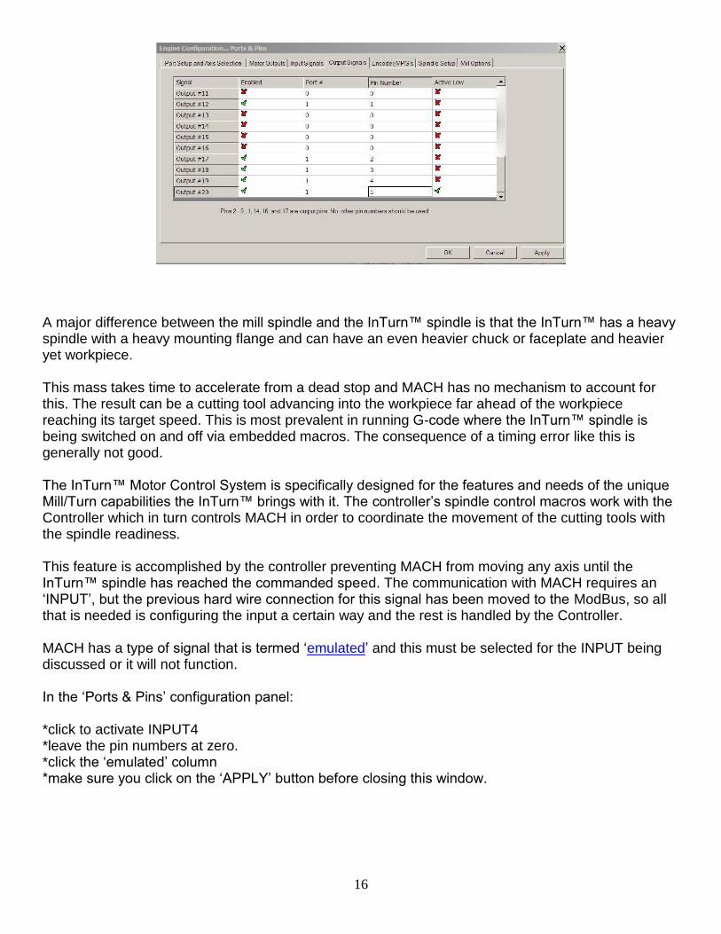
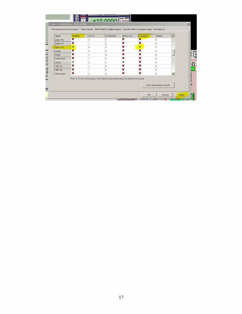
A major difference between the mill spindle and the InTurn™ spindle is that the InTurn™ has a heavy spindle with a heavy mounting flange and can have an even heavier chuck or faceplate and heavier yet workpiece. This mass takes time to accelerate from a dead stop and MACH has no mechanism to account for this. The result can be a cutting tool advancing into the workpiece far ahead of the workpiece reaching its target speed. This is most prevalent in running G-code where the InTurn™ spindle is being switched on and off via embedded macros. The consequence of a timing error like this is generally not good. The InTurn™ Motor Control System is specifically designed for the features and needs of the unique Mill/Turn capabilities the InTurn™ brings with it. The controller’s spindle control macros work with the Controller which in turn controls MACH in order to coordinate the movement of the cutting tools with the spindle readiness. This feature is accomplished by the controller preventing MACH from moving any axis until the InTurn™ spindle has reached the commanded speed. The communication with MACH requires an ‘INPUT’, but the previous hard wire connection for this signal has been moved to the ModBus, so all that is needed is configuring the input a certain way and the rest is handled by the Controller. MACH has a type of signal that is termed ‘emulated’ and this must be selected for the INPUT being discussed or it will not function. In the ‘Ports & Pins’ configuration panel: *click to activate INPUT4 *leave the pin numbers at zero. *click the ‘emulated’ column *make sure you click on the ‘APPLY’ button before closing this window.
17
18
Hardware and Wiring
4th axis HOME INDEX SENSOR connection: As of 11/15/14, the InTurn™ has inherited a new sensor developed for the InTurn™ Mill Spindles. This sensor is on a small PC board and required support components are located on the board so a simple wire hook up is all that is required. Connect wires from 4th axis home sensor to BOB. Connect the RED sensor power to 5V from the BOB. Connect the BLACK sensor ground to BOB ground. Note: for 5V BOB, both sides of the sensor can be fed from the same 5V. In this case, connect the RED and YELLOW wires both to the 5V supply. Connect the WHITE sensor output to any available BOB input pin. Go into the MACH ‘Configure Ports and Pins’ and assign the BOB input pin that was used to the ‘A’ Axis home and check ‘enable’ and ‘active high’. Remove the 4th axis cover plate and rotate the spindle until the tiny Shutter hole is within the sensor arms. Move the hole slowly past the sensor and observe the A home LED on The MACH diagnostic screen. It should light when the shutter hole passes the sensor. Note: there are two types of sensors. Those intended for more than 5V operation feature a Solid State Relay on the switched side. This is a small black 6 pin chip in the center of the PC board. These Sensors can switch up to 60V and the signal voltage is supplied on the YELLOW (or GREEN) wire and is switched on and off to the WHITE wire. The second type of sensor is identical except there is simply a jumper where the small black 6 pin chip would have been. If the sensor is switching a 5V signal (from a typical BOB that would be used with MACH3), then there is no need for a relay because the sensor is able to switch a 5V signal. In all cases, the LED side of the sensor is 5V DC and the BLACK ground wire connected to the SAME source as the 5V DC power is taken from. Controller Combo Board Functions The InTurn™ controller includes a remote circuit board that is typically mounted inside the CNC electronics enclosure. It is important to have the wires from the BOB to the board as short as possible. The board is not grounded by the mounting. Provide a separate ground as shown in the diagram. This board combines several functions onto one compact unit:
19
Digital Signal Synthesizer (clean Megahertz range pulse stream) SwapAxis function (switches the InTurn™ from Indexing to Turning) Line Driver (creates differential signals for Step and Dir)
PRE-WIRED CONNECTIONS: InTurn™ controller to combo board
See the attached wiring diagram
Connect wires to Your Servo Drive:
Step+ and Step- differential pairs. Use twisted pair wire. Direction + and Direction - Shielded CAT6 wire recommended. Note: some drives do not support differential pairs.
For those drives use only the + signals. Leave the – terminals unconnected
Wire with both foil and braided shielding is recommended. NOTE: Do NOT run power and signal wires in the same cable. Example: the two twisted pairs that are used for the STEP and DIR should be in a separate shielded cable. This is especially important with 24V industrial drive electronics. NOTE: Operation of the high power 24V signals in the same cable as differential signals will induce a spike in the STEP/DIR wires that will disable the Digital Signal Synthesizer on the InTurn™ Controller’s interface combo board.
Connect wires to Your Break Out Board:
‘A’ Axis STEP (color choice and Pin number choice by User) Select any available OUTPUT pin on your BOB Set MACH to output the A axis Step on this pin. Wire from this BOB Pin TO the A Step pin on the Combo Board ‘A’ Axis DIRection Connect in the same way as the Step Pin above
Connect wires to a 5 Volt DC power supply. The InTurn™ motor controller draws more power than early USB ports can supply, so it must be fed separately. The power supply wire in the InTurn™ USB cable is severed to prevent an overdraw which will shut down your PC’s USB port(s).
20
The most convenient place to power the unit is from the Combo board as shown on the diagram. Select a source of 5VDC and connect it to the appropriate pins on the Combo board, or connect to the pigtails that are already on those pins as you receive the product. 5V Power (Color choice by user – Red is suggested) A preferred source for clean filtered 5VDC is any hard drive power plug on your computer’s power supply. These are the red and the black wire next to it. You can take power from pins on your BOB if the BOB can supply at least 150mA. You can use a separate filtered and regulated 5Volt DC supply. In this case, you MUST connect a wire from the power supply ground to the PC ground. If you do not do this, current from the power supply can travel over the USB cable seeking ground (this is called a ground loop). This will completely disrupt the USB communication. POWER GROUND (color choice by user – Black is Suggested) Be sure to connect the InTurn™ power ground to the SAME source that you got the 5VDC power from.
21
Adding your system Parameters into the InTurn™ Controller
AutoConfigure
The AutoConfigure feature is included in all Gen2 controllers and is available as a firmware only upgrade for Gen1 controllers.
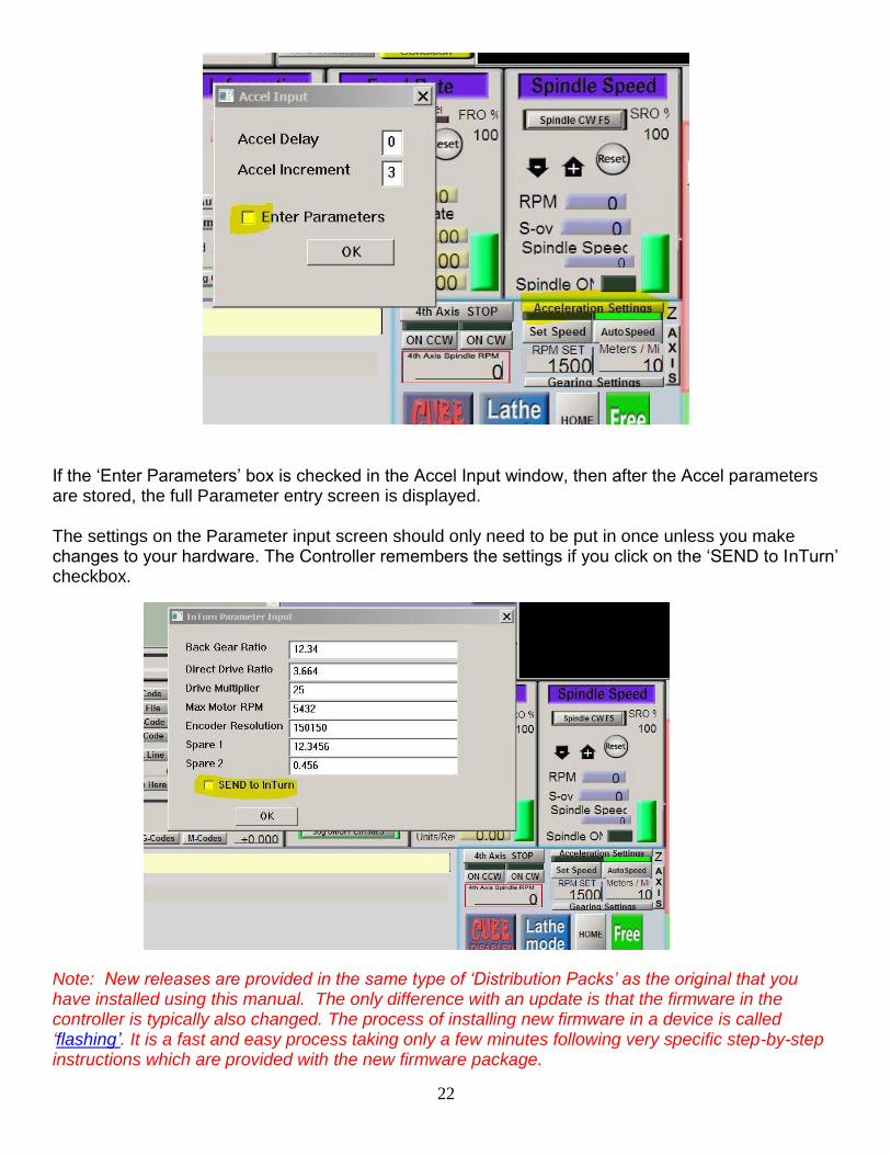
The InTurn™ Motor Control, system does internal calculations to set and maintain commanded speed. The formulas are based on parameters that vary from machine to machine. The parameters are * Maximum motor RPM – this is the motor itself and not the 4th axis spindle. * Encoder resolution. This need to be in ‘counts’ or ‘steps’ and not ‘lines’
Encoders typically operate in quadrature so the count is 4x the lines. * Main Drive Ratio – this is the belt ration without double reduction (back gear). * Back Gear Ratio – borrowing the term from lathes, ‘Back Gear is the extra
reduction afforded by additional gearing in ‘back’ of the head. For the 4th axis, this is the extra belt and idler setup. If your 4th axis does not have the double reduction setup, enter the Main ration again here.
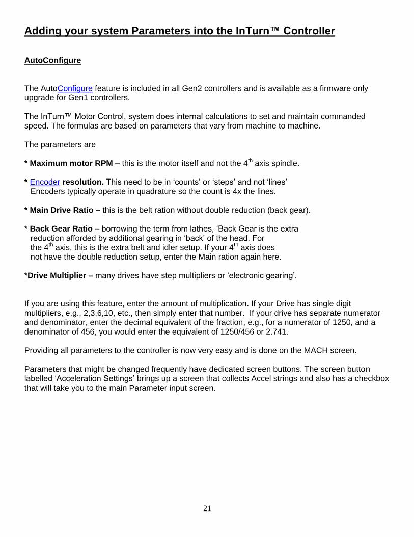
*Drive Multiplier – many drives have step multipliers or ‘electronic gearing’. If you are using this feature, enter the amount of multiplication. If your Drive has single digit multipliers, e.g., 2,3,6,10, etc., then simply enter that number. If your drive has separate numerator and denominator, enter the decimal equivalent of the fraction, e.g., for a numerator of 1250, and a denominator of 456, you would enter the equivalent of 1250/456 or 2.741. Providing all parameters to the controller is now very easy and is done on the MACH screen. Parameters that might be changed frequently have dedicated screen buttons. The screen button labelled ‘Acceleration Settings’ brings up a screen that collects Accel strings and also has a checkbox that will take you to the main Parameter input screen.
22
If the ‘Enter Parameters’ box is checked in the Accel Input window, then after the Accel parameters are stored, the full Parameter entry screen is displayed. The settings on the Parameter input screen should only need to be put in once unless you make changes to your hardware. The Controller remembers the settings if you click on the ‘SEND to InTurn’ checkbox. Note: New releases are provided in the same type of ‘Distribution Packs’ as the original that you have installed using this manual. The only difference with an update is that the firmware in the controller is typically also changed. The process of installing new firmware in a device is called ‘flashing’. It is a fast and easy process taking only a few minutes following very specific step-by-step instructions which are provided with the new firmware package.
23
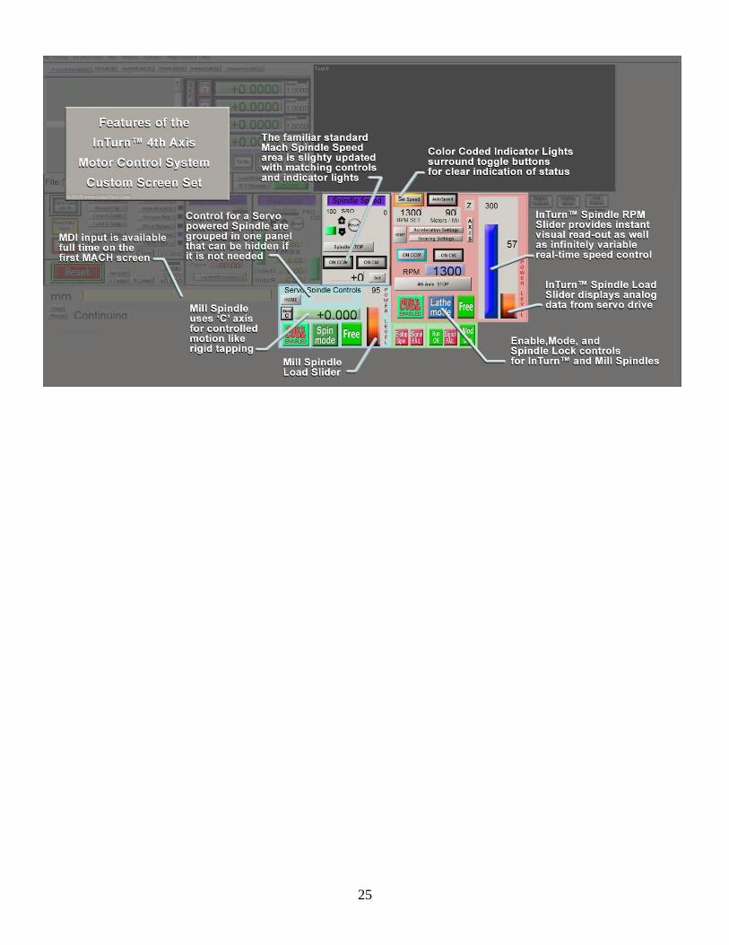
Addendum A Release Notes
The Latest version of the firmware as of 04/21/2015 is: InTurnFirmwareGen2WORK34SF
InTurn™ Motor Control System GEN2 USB for MACH3 Ver. 34 The InTurn™ screens have been updated with some controls re-grouped and new ‘lighted’ buttons in place of the previous separate button and indicator light. Controls for a servo controlled spindle have been grouped together so that they can be *blanked off for systems that do not have a servo powered spindle. A power monitor has been added for both the InTurn™ spindle and the Mill spindle. These features require a drive that has an analog output that provides torque data. The InTurn™ processor handles the Analog/Digital conversion and sends the data to MACH for display on-screen. *provision for blanking the area will be added in the next update Previous versions: As of version 33 of the firmware, an ‘emulated’ INPUT4 has been set up to replace the old hard wired INPUT4. INPUT4 is used between the InTurn™ Controller and MACH to facilitate coordinating the axis motion with the InTurn™ Working in conjunction with the other safety interlocks, the Controller provides an ‘Automatic Pause’ in axis movement while the InTurn™ spindle is coming up to speed, preventing an early entry of a cutting tool into a workpiece that has not reached its target speed. As of version 32 of the firmware, the user supplied operating parameters (max RPM, encoder res, etc.) are collected on-screen by a comprehensive script that also provides for the confirmed transfer of the parameters to the InTurn™ Controller. The acceleration parameters, which may need to be changed from job to job are accessed by a screen button labeled ‘Acceleration Settings’. In the Accel setting window is a checkbox that will bring up the full parameter input window. Once all of the parameters are entered, check the box to send them to the InTurn™ Controller. The new parameters should take effect immediately, but it is a good idea to confirm the status with these steps: 1) shut down Mach3 2) power off the controller 3) turn the speed knob halfway up on the controller 4) power up the controller The controller will now continuously display pages showing the parameters which are stored in the controller’s memory and also the firmware version loaded. 5) turn the speed knob to Min 6) start Mach3 A bug in the Autospeed mode was introduced in Ver 30 or 31 where, in Metric units, any SFM setting above 32 would cause the RPM to reverse and start dropping. This has been fixed. Previous updates: The InTurn™ now collects the ‘Units’ setting (Metric or Inches) from Mach on startup. It is no longer necessary to change from one to the other in order for the Controller to make the correct setting.
24
Clicking the Spindle Stop button will now interrupt an ongoing ‘Speed Match’ and immediately stop acceleration and return the spindle to a stop Initialization Macro sets the InTurn™ to a safe condition at initialization and reset. Also displays the AutoSpeed parameters on-screen for the Follow axis (Z or Y) and whether the controller is using Metric or Inch calculations (should match whatever Mach is set to). This macro “M4444’ must be added to the init string (see instructions). Put MACH into E-stop by clicking the big red reset button. The controller will go into E-stop and: The red E-stop LED will begin flashing The LCD screen will change to 'E-Stop' and will begin a counter showing how long it has been in E-stop The screen button labeled 'Run OK' turns red and says 'InTurn Estop' The above feature is now standard. The E-stop comes across the ModBus so there is no longer a physical wire connection needed. If the E-stop wire is connected, remove it. Click the Reset button in MACH and MACH should move to a ready status and the controller will follow. Click reset again to put MACH into E-stop - the described E-stop condition will appear WHILE in E-stop. throw the Spindle ON/OFF switch to ON. The controller will command a constant step signal of approx. 10kHz to be produced. CAUTION: the InTurn™ drive *should* be disabled at this point so there should be no movement. IF you have no enable/disable capable drive or if you have the drive permanently enabled, it will begin to turn slowly if the step signal is connected to the drive during this test. Turning the Spindle switch OFF or leaving E-stop mode will stop the spindle immediately and normal operation will resume. Other features: Controller parameters are collected and sent to the controller over ModBus by a set of macros. M9200, M9201, M9202. Run these from the MDI entry line and you will be prompted for parameter input. The controller screen will change to indicate incoming parameters each time a NEW parameter is input. If you do not change the existing value, no parameter is sent. Previous Features: Turn on the controller with the Spindle ON/Off switch (largest one on the right side) and the controller goes into 'program mode'. This is for communication with the Windows program 'InTurn™ Configurator' and is no longer used. Turn on the Controller with the speed control knob half turned way up and the Controller goes into 'reporting' mode and displays a repeating sequence of screens containing all of the controller's stored parameters as well as the Firmware version number. Turning the knob to min puts the controller back into normal operation without requiring a restart. Temporary Debugging aids: The manual Control LED (square red) is lit for each ModBus read. This will vary from somewhat slow flashing to what appears to be a steady ON condition. When entering new parameters, a series of pop-up windows show the macros progress in disassembling the floating point numbers for transmission over ModBus. These do not require any attention, just click past them. Reference Materials: Voltage Divider Calculator http://www.raltron.com/cust/tools/voltage_divider.asp
25
26
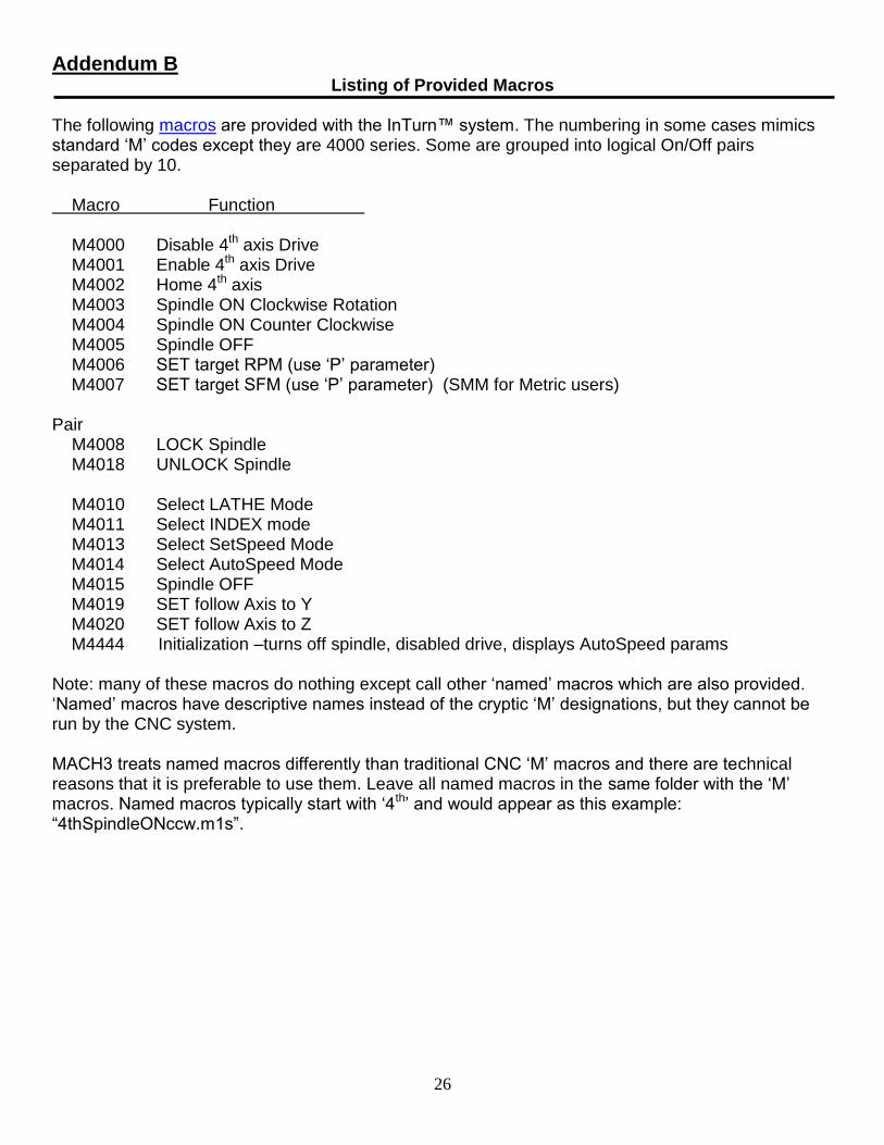
Addendum B Listing of Provided Macros
The following macros are provided with the InTurn™ system. The numbering in some cases mimics standard ‘M’ codes except they are 4000 series. Some are grouped into logical On/Off pairs separated by 10. Macro Function M4000 Disable 4th axis Drive M4001 Enable 4th axis Drive M4002 Home 4th axis M4003 Spindle ON Clockwise Rotation M4004 Spindle ON Counter Clockwise M4005 Spindle OFF M4006 SET target RPM (use ‘P’ parameter) M4007 SET target SFM (use ‘P’ parameter) (SMM for Metric users) Pair M4008 LOCK Spindle M4018 UNLOCK Spindle M4010 Select LATHE Mode M4011 Select INDEX mode M4013 Select SetSpeed Mode M4014 Select AutoSpeed Mode M4015 Spindle OFF M4019 SET follow Axis to Y M4020 SET follow Axis to Z M4444 Initialization –turns off spindle, disabled drive, displays AutoSpeed params Note: many of these macros do nothing except call other ‘named’ macros which are also provided. ‘Named’ macros have descriptive names instead of the cryptic ‘M’ designations, but they cannot be run by the CNC system. MACH3 treats named macros differently than traditional CNC ‘M’ macros and there are technical reasons that it is preferable to use them. Leave all named macros in the same folder with the ‘M’ macros. Named macros typically start with ‘4th’ and would appear as this example: “4thSpindleONccw.m1s”.
27
Addendum C Definitions
CNC Terminology: CNC: Computer Numerical Control – this just means a computer controlling something. We are surrounded by CNC machines in our everyday life typically without even recognizing it. A digital alarm clock is, in fact, technically a CNC machine, as is any coffee pot that will make coffee at a pre-set time. Any devices with the word ‘programmable’ in the title, as in thermostats or garage door openers, are again, in fact, CNC machines. Your DVD player is as much a CNC machine as an industrial robot welding a car together. G-Code: A standardized language that contains instruction on where and when to move various parts of a machine. Indexing: The action of rotating an axis to a specific azimuth (number of degrees) †M-Code: An instruction contained within the G-code ‘Program’ that performs a utility function unrelated to motion, like turning parts of the machine (Spindle motor, coolant, etc.) on and off. Also used for controlling the ‘flow’ of the G-code by providing for organized execution of the various parts of the program. i.e., pretty much everything that is not a command to move something. Mill/Turn: Combining the functions of Milling and Turning operations on the same machine. Normally a milling machine and a lathe would be required to carry out both functions. †See Macro under Computer Terminology
Computer Terminology: Configure: A potentially scary term that actually describes something every single person does every day. ‘Configuring’ a machine is the simply act of entering information telling a machine what to do. Setting an alarm clock is ‘configuring’ the machine. Setting the temperature on a thermostat is ‘configuring’ the machine. Any information that is variable and cannot be determined automatically by the machine must be entered by an ‘operator’. An oven does not know the correct temperature to bake a particular item, so the ‘operator’ (the cook) looks it up in a ‘spec’ (recipe) and ‘configures’ the oven for the task. CNC components that require ‘configuration’ normally come with that ‘recipe’ that tells the operator exactly what to enter into the machine depending on the way the machine is needed to operate. Drivers: A small program that runs continuously and handles communications and data conversions between the computer and an attached device (Printer, Mouse, Motion Controller, etc.). Firmware: ‘Programs’ that reside permanently in the computer’s memory (even when the computer is turned off). Because such programs are ‘resident’ in the computer’s memory, they can execute (or ‘run’) at any time (usually on power-up) without needing to be loaded from some storage media. Flashing: Describing the process of imprinting ‘Firmware’ on ‘permanent’ memory, this is a bit of slang that may have derived from the term ‘Flash’ memory, which is one of several terms used to describe the type of memory that can retain its contents without power .
28
†Macro: Similar to ‘batch files’ or ‘scripts’. In general these are ‘programs’ created by simply listing commands similar to what you might type into your computer. These are grouped together in the same file, one after the other, in the same order you would type them. When the name of that file is used, the commands within it are executed as if they were being typed in (really fast) by an operator. Batch files would be the simplest form, containing literally the exact words you would type. Macros are a bit more complicated, but still generally just a list of Commands that you might type into a running piece of software. Scripts are more powerful and more complicated and have structure, rules and often their own special commands and functions that work exclusively within the script. ‡ModBus: Another potentially scary term that is often mistaken for a physical device that the user needs to purchase and install. ModBus is not a physical thing. It is just a set of rules for communication between machines. Much like a spoken language, everyone in the conversation needs to understand the same language in order to pass information back and forth successfully. So, it can be imagined that any machine that ‘speaks’ ModBus can talk to another machine that also speaks ModBus. Two Spanish speakers can have a conversation in person, on the phone, via letter, e-mail, IM or smoke signals. ModBus only defines the language, not the method by which is it transmitted. This is `an important distinction to remember. † See M-Code under CNC Terminology ‡ Further description under Signals and Hardware Terminology Shortcut: An icon on the desktop that actually contains a macro which starts a program under a prescribed set of conditions that the user can pre-load into the shortcut. Shortcut, in this context, is a general Windows term, but specific examples for MACH are included in the Installation Manual. Software: ‘Programs’ that can be run on a computer, but are not permanently installed on the computer. The data is permanently stored on some form of media--floppy disk, hard drive, thumb drive, etc., and must be loaded into the computer’s memory before they can be run. When you click on an Icon on your windows desktop, you are telling the computer to go find and load that program from the hard drive into memory and start running the program. InTurn™ Terminology: AutoSpeed: Spindle speed is calculated continuously to maintain SFM based on distance of cutting tool to work. Back Gear: A term borrowed from lathes. A countershaft which doubles or triples the ratio. (‘Low Gear’) Configuration Mode (obsolete): Condition in which the controller was ready to receive parameter data. DSS (Digital Signal Synthesizer): Special dedicated processor for generating very high speed signals. Direct Drive: An arrangement with two pulleys and one belt. (analogous of ‘high gear’) Follow Axis or Tracking Axis: Sets which Axis coordinates are tracked to calculate RPM to achieve entered SFM.
29
Load Meter: An animated real-time bar graph that displays the percentage of maximum motor torque being used. Manual Mode (obsolete): Condition for manually controlling the 4th axis for non MACH systems Reporting Mode: Condition where the Controller continuously scrolls the internally stored parameters. SFM (or MPM): Surface Feet per Minute -or- Meters Per Minute – speed at which a cutting tool moves over a workpiece. SSR (Solid State Relay): A relay for using a tiny signal to switch large loads that does not use physical contacts.
SetSpeed: Spindle is matched to a set speed entered by the user or by macro command. Surrogate Signal: Some drives send an alarm when they are disabled causing MACH to go into an unwanted E-stop. A temporary ‘fake’ signal is generated to prevent this from happening. MACH Terminology: Brains: This is actually a MACH-specific term. It is their name for specific control programs that are based on ‘Ladder Logic’ and run continuously in the background to perform tasks that need to be ongoing at all times. Emulated: Signals usually come into MACH over physical wires connected to pins. A purpose of configuration is to tell MACH which pin is used for each signal. Occasionally, a signal may be needed that does not come in over a wire, but is instead ‘emulated’ by some internal software source. When emulated, MACH would not need to monitor the pin because the INPUT is being controlled by software. Loader: The ‘startup’ program for Mach that will stop to ask the user which ‘profile’ to use. The ‘Loader’ then starts MACH using that profile which contains all of your settings. To accomplish the same thing, but without answering the same question each time, a Windows ‘shortcut’ can be made which automatically starts Mach with your profile. Detailed instructions on how to do this are in the Installation Manual. Mach3: A software ‘program’ that reads a specific form of instructions called ‘G-Code’ and controls positioning motors as needed to perform the moves contained in the G-code. Macro Pump: A special kind of Macro that runs continuously in the background. Profile: Mach 3 performs in a specific way based on how it is told to behave. The choices that you make during the ‘configuration’ process are grouped together and stored as a named ‘profile’. This way, you can simply tell MACH, each time it starts that you want it to use your profile to gather all of the settings.
30
Servo Motor Terminology: Enable/Disable: The ability of a drive to release the motor to freewheel (disabled). Encoder: a device that is connected to the motor shaft and measures the motor rotation in small increments called ‘lines’ or ‘counts’. These are converted into electrical pulses that are sent to the servo Drive so that the motor position is known. Pulse or Signal Multiplier a.k.a. ‘Electronic Gearing’: Some drives have the capacity to receive extremely high speed signals. If the CNC system is not capable of producing a very high speed signal, an electronic ‘ratio’ is established so that the slower signal is ‘multiplied’ to achieve the very high data rates needed by the drive. For example, if the multiplier is set at 10, every pulse coming into the drive is counted as if it were 10 pulses. RPM and MAX RPM: Revolutions Per Minute. The speed at which the motor is turning. The MAXimum for each motor is established by the manufacturer and generally printed on a plate attached to the motor. Signals and Hardware Terminology: A/D Converter: Computers process and move digital data; however, there is a need, particularly in instrumentation, like a thermostat, for example, to have analog signals. Most of us are interested in the temperatures between freezing and boiling for example, so a signal that can represent any value is needed. Because computers can only process digital signals, passing analog data to a computer requires an Analog-to-Digital converter, or A/D for short. Analog Signals: Like a digital signal, analog represents the values using voltage; but unlike digital, where you only have high and low, analog can represent everything in between. The voltage is normally not divided into tiny slices of time like digital, but rather the continuous presence of some particular variable voltage. Break Out Board: Very simple concept. A plug with any tiny pins at each end, such as a typical printer cable, is a difficult device to connect individual wires to. To solve this dilemma, a BOB simply has the correct plug for the many pins in the cable connector and ‘Breaks Out’ each of those wires to an accessible terminal (typically a screw clamp type).
COM Port: COMmunication ports carry a Serial signal (pulses lined up on a single wire). Also
physically and electronically defined by IBM, but targeted at devices like modems that carry serial signals Differential Signals: Keyword here is ‘different’. The signal is split into two mirror images and transmitted across a pair of wires that are twisted together (Twisted pair, or UTP). Unlike single ended signals which are measured between the signal and ground, differential signals measure the differential (difference) between the two wires. The operational theory is that any interference would affect both wires equally and since they are opposite polarity, that interference would cancel itself out. Far more reliable and having faster available speeds and limited need for shielding. More expensive and dedicated chips are needed to convert to and from the differential condition.
31
Digital Signals: Any signal that is composed of digital (on/off, or binary) information. In written form, binary looks like this: 11000111100100101, but you cannot send ones and zeros over a wire, so the one is represented by a voltage being present and the zero by the absence of voltage. So, if you could see a digital signal, it would look like this 5v 5v 0v 0v 0v 5v 0v and so on, with the ‘punctuation’ separating the characters (pulses) being provided by timing. Ethernet: An old communication protocol; but one that has been continuously updated and is still current. Physical wiring for modern Ethernet is twisted pair wire terminated in RJ45 connectors. Input Output (I/O): Signals that go into and out of a device. It is important to recognize that with MACH3, an ‘Input’ is both physical and virtual at the same time. In other words, there is typically a bunch of physical pins or terminals on a device and those are typically numbered. The numbers assigned to each physical pin is contained in a document called, not surprisingly, a ‘Pin-out’ diagram. Pin numbers are uniformly applied to ‘standardized’ connectors like a parallel, serial, USB, Ethernet and so on. However, each manufacturer of a Break-out-board, Motion Control Device, or 4th axis motor controller will have assigned their own numbers to the non-standard pins on their particular device. NOTE: MACH documentation adds confusion by identifying certain physicals pins, by pin number, as either input or output. MACH3 also uses the Term INPUT#xx and OUTPUT#xx as the ‘names’ for additional signals. When referring to a physical ‘pin’ (or a numbered physical terminal), the words ‘input’ and ‘output’ refer to the DIRECTION that the signal travels. For PINS: ‘output’ meaning a signal that travels from Mach3 – TO – a device, for example, to control a pump or valve. ‘input’ meaning a signal that travels into Mach3 – FROM – a device, for example a limit switch or Estop from a drive. For MACH3: INPUT#xx is a ‘name’ given to any signal that is not already pre-defined inside MACH. OUTPUT#xx, as above, but for outbound signals, for example the InTurn™ Internal Spindle Lock. Unfortunately, these ’names’ cannot be changed to something descriptive of what you are actually using them for. If you used ‘OUTPUT#15’ to control the InTurn™ Spindle lock, for example, it would be more comprehensible if the name ‘OUTPUT#15’ could be changed to ‘InTurn™ Spindle Lock’. That is not possible, so it is a good practice to document which INPUT and OUTPUT numbers are used for what purpose in your particular system. †ModBus: One of the very early protocols developed for computing devices to communicate. Hardware is not part of the spec and therefore ModBus is typically run across whatever topology (wiring and modern protocol) that is available. Probably because computers were quite slow and limited at the time, ModBus has both binary and textural formats and it can only carry 16 bit data chunks (integers). It is a crude master/slave arrangement where only the master can initiate communication and while there is error detection, there is no recovery mechanism. Bad data is simply discarded. †Further description under Software Terminology
32
Motion Control Board: Personal computers are ‘general purpose’ devices that perform an enormous amount of different functions, but are not designed nor intended to be extremely powerful in any one type of processing. For computationally intensive functions, often a separate dedicated processor is used so that the Central Processing Unit (CPU) is free to do the dozens of tasks required to run your computer. The dedicated processor on a graphics card is a good example. Generating high quality, high speed digital signals is one of the tasks that a general purpose CPU is not well suited for and Digital Signal Synthesizers (DSS) are sometimes added to the mix to perform that task. The DSS may be a separate chip or built into a much larger chip that also contains other dedicated processors for other tasks. However, it is impossible for a user to integrate a single chip into the CNC control scheme, so vendors stick then on a PC board and usually add convenience and support features as well. Some of these boards have rows of screw terminals for the signals and therefore do not require a separate BOB. Likewise, the InTurn™ 4th Axis Motor Controller has a dedicated DSS mounted on a separate small PC board with screw terminals for the needed signal wires and also contains the chips needed for the ‘swapaxis’ function and also a line driver to create ‘differential’ signals. Similarly, a Motion Control Board would have a dedicated processor for calculating axis moves and generating high-speed step/dir signals. Parallel Port: This is both a communication standard and a physical connector standard defined by IBM for the first personal computer. Because all manufacturers followed that standard, any parallel port printer can be simply plugged into any parallel port (sometimes mistakenly called a printer port) Single Ended Signals: A ‘single wire’ signal that has a high state and a low state for digital data. Susceptible to interference from RFI, EMI and any other type of stray radiation. Reliability in long runs is questionable. Shielded, low impedance wire is required to protect the signal from interference. USB: The intended replacement for the aging COM ports. Modern connectors, buss arrangement with hubs and switches. Very fast and with a pathway to even faster speeds. Standardized protocols. The extreme complicity in creating ‘native’ USB devices led many manufacturers to opt for the ‘quick fix’ of using single chip converters that allowed the old Serial protocol to be carried over the newer USB standard. The problem with this scheme is that the ‘trick’ requires drivers (small software programs to control the converter chip and create a ‘fake’ COM port in the computer). The drivers for competing brands and even versions within the same brand often trip over each other and the ‘emulated’ COM ports are assigned, by number, to specific USB ports, which can get reassigned or simply lost when a new device is plugged in causing yet another ‘converter’ driver to load. USB carries power for USB devices and the amount of power available has climbed steadily as USB upgraded from 1 to 2 and so on. If too much power is drawn from a USB port (a USB2 device plugged into a USB1 port, for example), the computer will shut off the port and many computers must be rebooted from a power off state to recover. A USB device which requires more power than the USB spec allows must be powered separately, which often leads to ground loops and other signaling problems.