Embed Size (px)
Citation preview
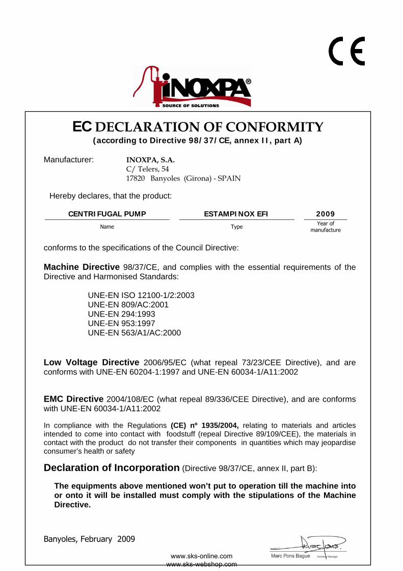
INSTALLATION, SERVICE AND MAINTENANCE INSTRUCTIONS
ESTAMPINOX EFI
01.020.30.04EN ED. 2009/02
Waalwijk (NL) +31 (0) 416-566060Drachten (NL) +31 (0) 512 540354Berchem (B) +32 (0) 3232 6332
www.sks-online.com
www.sks-online.com www.sks-webshop.com
EC DECLARATION OF CONFORMITY (according to Directive 98/37/CE, annex II, part A)
Manufacturer: INOXPA, S.A.
C/ Telers, 54 17820 Banyoles (Girona) - SPAIN
Hereby declares, that the product:
CENTRIFUGAL PUMP ESTAMPINOX EFI 2009
Name Type Year of manufacture
conforms to the specifications of the Council Directive: Machine Directive 98/37/CE, and complies with the essential requirements of the Directive and Harmonised Standards: UNE-EN ISO 12100-1/2:2003 UNE-EN 809/AC:2001 UNE-EN 294:1993 UNE-EN 953:1997 UNE-EN 563/A1/AC:2000
Low Voltage Directive 2006/95/EC (what repeal 73/23/CEE Directive), and are conforms with UNE-EN 60204-1:1997 and UNE-EN 60034-1/A11:2002 EMC Directive 2004/108/EC (what repeal 89/336/CEE Directive), and are conforms with UNE-EN 60034-1/A11:2002 In compliance with the Regulations (CE) nº 1935/2004, relating to materials and articles intended to come into contact with foodstuff (repeal Directive 89/109/CEE), the materials in contact with the product do not transfer their components in quantities which may jeopardise consumer’s health or safety
Declaration of Incorporation (Directive 98/37/CE, annex II, part B):
The equipments above mentioned won’t put to operation till the machine into or onto it will be installed must comply with the stipulations of the Machine Directive.
Banyoles, February 2009
www.sks-online.com www.sks-webshop.com
ED. 2009/02 1.Safety 3
1. Safety 1.1. INSTRUCTION MANUAL This instruction manual contains information on the reception, installation, operation, fitting, stripping and maintenance for the ESTAMPINOX EFI pump. The information given herein is based on the most up-to-date data available. INOXPA reserves the right to modify this instructions manual without having to give prior notice. 1.2. START-UP INSTRUCTIONS This instruction manual contains vital and useful information for properly operating the pump and for keeping it in good running condition. Not only should the safety instructions set forth in this chapter be carefully read before putting the pump into operation, but those concerned must also familiarise themselves with the operating features of the pump and strictly adhere to the instructions given herein. It is extremely important that these instructions be kept in a set place near the installation. 1.3. SAFETY 1.3.1. Warning signs
Danger for people in general.
Danger of injury caused by rotating parts of the equipment.
Danger! Electricity.
Danger! Caustic or corrosive agents.
Danger! Suspended loads.
Danger to the proper operating of the machine.
Obligation to ensure safety at work.
Use of safety goggles obligatory.
1.4. GENERAL SAFETY INSTRUCTIONS
Please read the instruction manual carefully before installing and commissioning the pump. Should you have any doubts or queries, contact INOXPA.
1.4.1. During the installation
You must always bear in mind the Technical Specifications set forth in Chapter 8. Do not put the pump into operation before connecting it to the pipes. Do not put the pump into operation if the cover of the pump has not been fitted and the impeller fixed in the pump. Check that the motor specifications are correct, especially if there is a special risk of explosion due to the work conditions.
During the installation procedure, all the electrical work must be carried out by duly authorised personnel.
1.4.2. During operation
You must always bear in mind the Technical Specifications set forth in Chapter 8. The limit values that have been set must NEVER be exceeded.
NEVER touch the pump or pipes whenever the pump is being used to decant hot liquids or during the cleaning procedure.
www.sks-online.com www.sks-webshop.com
4 1.Safety ED. 2009/02
The pump has moving parts. Do not put your fingers into the pump when it is operating.
NEVER work with the suction and the delivery valves shut off. NEVER directly sprinkle the electric motor with water. Standard motor protection is IP-55: dust and water sprinkling protection.
1.4.3. During maintenance
You must always bear in mind the Technical Specifications set forth in Chapter 8. NEVER strip the pump down until the pipes have been drained. Remember that there will always be some liquid left in the pump casing (if it has not been fitted with a drain). Always remember that the liquid that has been pumped may be dangerous or subject to high temperatures. For situations of this type, please consult the prevailing regulations in the country in question. Do not leave loose parts on the floor.
ALWAYS turn the power supply to the pump off before embarking on maintenance work. Take out the fuses and disconnect the wires from the motor terminals. All electrical work must be carried out by duly authorised personnel.
1.4.4. In accordance with the instructions Any failure to comply with the instructions could lead to a hazard for the operators, the atmospheric conditions of the room, and the machine, and it could lead to a loss to any right to make a claim for damages. Such non-compliance could bring with it the following risks:
• Important operating failures of the machine / plant. • Failure to comply with specific maintenance and repair procedures. • Potential electrical, mechanical and chemical hazards. • Atmospheric conditions in the room could be hazardous due to the release of chemical substances.
1.4.5. Warranty We wish to point out that any warranty issued will be null and void and that we are entitled to an indemnity for any civil liability claim for products which might be filed by third parties if:
• Operation and maintenance work has not been done following the corresponding instructions; the repairs have not been made by our personnel or have been made without our written authorization;
• Modifications are made to our material without prior written authorization; • The parts or lubricants used are not original INOXPA parts/lubricants; • The material has been improperly used due to error or negligence or have not been used according to the indications
and the intended purpose. • The parts of the pump have been damaged as a result of having been exposed to strong pressure as there was no
pressure relief valve. The General Delivery Terms which you have already received are also applicable.
No modification can be made to the machine without the prior consent of the manufacturer. For your safety, use spare parts and original accessories. The use of other parts exempts the manufacturer from any and all responsibility. Any change in operating conditions can only be done with the prior written consent of INOXPA.
In the event of doubt or should you require a fuller explanation on particular data (adjustment, assembly, disassembly...), please do not hesitate to contact us
www.sks-online.com www.sks-webshop.com
ED. 2009/02 2.Index 5
2. Index
1. Safety
1.1. INSTRUCTION MANUAL ................................................................................................... 3 1.2. START-UP INSTRUCTIONS ............................................................................................... 3 1.3. SAFETY ........................................................................................................................... 3 1.4. GENERAL SAFETY INSTRUCTIONS.................................................................................... 3
2. Index
3. General Information
3.1. DESCRIPTION ................................................................................................................. 6 3.2. FIELD OF APPLICATION ................................................................................................... 6
4. Installation
4.1. PUMP RECEPTION ........................................................................................................... 7 4.2. TRANSPORT AND STORAGE ............................................................................................. 7 4.3. LOCATION ...................................................................................................................... 8 4.4. PIPES ............................................................................................................................. 8 4.5. SHUT-OFF VALVES .......................................................................................................... 8 4.6. ELECTRICAL INSTALLATION ............................................................................................ 8
5. Start-up
5.1. START-UP ....................................................................................................................... 9
6. Operating problems
7. Maintenance
7.1. GENERAL MAINTENANCE ................................................................................................11 7.2. STORAGE .......................................................................................................................11 7.3. CLEANING ......................................................................................................................11 7.4. PUMP DISASSEMBLY ......................................................................................................12 7.5. PUMP ASSEMBLY ............................................................................................................13
8. Technical Specifications
8.1. TECHNICAL SPECIFICATIONS .........................................................................................15 8.2. WEIGHTS .......................................................................................................................15 8.3. ESTAMPINOX EFI DIMENSIONS .......................................................................................16 8.4. ESTAMPINOX EFI DIMENSIONS WITH TROLLEY...............................................................17 8.5. ESTAMPINOX EFI MR DIMENSIONS .................................................................................17 8.6. ESTAMPINOX EFI PUMP MOTOR COUPLING DIMENSIONS ................................................18 8.7. PARTS LIST ESTAMPINOX EFI PUMP ...............................................................................19 8.8. PARTS LIST ESTAMPINOX EFI MR PUMP ..........................................................................20 8.9. ESTAMPINOX EFI PUMP SECTION ...................................................................................21 8.10. PARTS LIST ESTAMPINOX EFI PUMP .............................................................................22 8.11. PARTS LIST ESTAMPINOX EFI MR PUMP ........................................................................23
www.sks-online.com www.sks-webshop.com

6 3.General Information ED. 2009/02
3. General Information 3.1. DESCRIPTION INOXPA ESTAMPINOX EFI series centrifugal pumps have designed for to pump water and compatible liquids with AISI 316L stainless steel. The ESTAMPINOX EFI series has been especially designed to comply with auxiliary services required by the food industry. The impeller is of open design and made of one single piece. Mechanical seal friction surfaces are ceramic, graphite and the NBR o-rings in the standard version. Constructive options more significant for this pumps are: * pump with stainless steel shroud * pump with trolley * control panel with stop/start, contactor and emergency stop push button Motor IEC. Protection IP-55. Class F insulation. Three-phase 220-240 / 380-420 at 50 Hz. This equipment is suitable for his use in food process. 3.2. FIELD OF APPLICATION
[m] [ft]
H
Q/
H
Q/
[m] [ft]
Each pump has a limited field of application. The pump in question was selected for certain pumping conditions at the time the order was made. INOXPA is not liable for any damages that might arise if the information furnished by the purchaser is incomplete (nature of the liquid, RPM…).
www.sks-online.com www.sks-webshop.com
ED. 2009/02 4.Installation 7
Serial number
4. Installation 4.1. PUMP RECEPTION
INOXPA is not responsible for any deterioration of the material as a result of its transportation or unpacking. Visually check that the packing has not suffered any damage.
The pump will be accompanied by the following documentation:
• Dispatch notes. • Pump Instruction and Service Manual. • Motor Instruction and Service Manual (*). • (*) If the pump has been supplied with a motor from INOXPA.
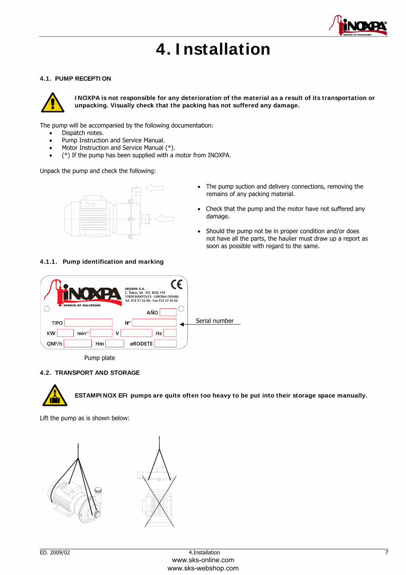
Unpack the pump and check the following:
• The pump suction and delivery connections, removing the remains of any packing material.
• Check that the pump and the motor have not suffered any
damage. • Should the pump not be in proper condition and/or does
not have all the parts, the haulier must draw up a report as soon as possible with regard to the same.
4.1.1. Pump identification and marking
Pump plate
4.2. TRANSPORT AND STORAGE
ESTAMPINOX EFI pumps are quite often too heavy to be put into their storage space manually.
Lift the pump as is shown below:
www.sks-online.com www.sks-webshop.com
8 4.Installation ED. 2009/02
Never lift the plant raising it by the pump.
4.3. LOCATION • Position the pump as near as possible to the suction tank, and whenever possible below the level of the liquid. • Place the pump in such a way that there is enough space around it to provide access both to the same and to the motor.
(See Chapter 8. Technical Specifications to consult dimensions and weights). • Place the pump on a level and flat surface.
Install the pump in such a way that it can be properly ventilated. If the pump is to be installed outside, it must be done so under cover. Its positioning must enable easy access for any inspection and maintenance operations that may need to be carried out.
4.4. PIPES • In general, suction and delivery pipes should be fitted in straight stretches, with the minimum amount of elbows and
accessories, in order reduce, as far as possible, any load loss that might be produced by friction. • Make sure that the pump mouths are well aligned with respect to the piping, and that they are similar in diameter to that of
the pipe connections. • Position the pump are near as possible to the suction tank, and whenever possible below the level of the liquid, or even
lower with respect to the tank in order for the static suction head be at its maximum. • Place brackets for the piping as near as possible to the suction and delivery mouths of the pump. 4.5. SHUT-OFF VALVES The pump can be isolated for the purpose of carrying out maintenance work. To this end, shut-off valves should be fitted at the pump’s suction and delivery connections. These valves must ALWAYS be open whenever the pump is operating. 4.6. ELECTRICAL INSTALLATION
Leave the connecting of the electrical motors to qualified personnel. Take the necessary measures to prevent any breakdowns in the connections and wires.
The electrical equipment, the terminals and the components of the control systems may still carry an electric charge even when disconnected. Contact with them may put the safety of operators at risk, or cause irreparable damage to the material. Before manoeuvring the pump, make sure that the electric box is switched off.
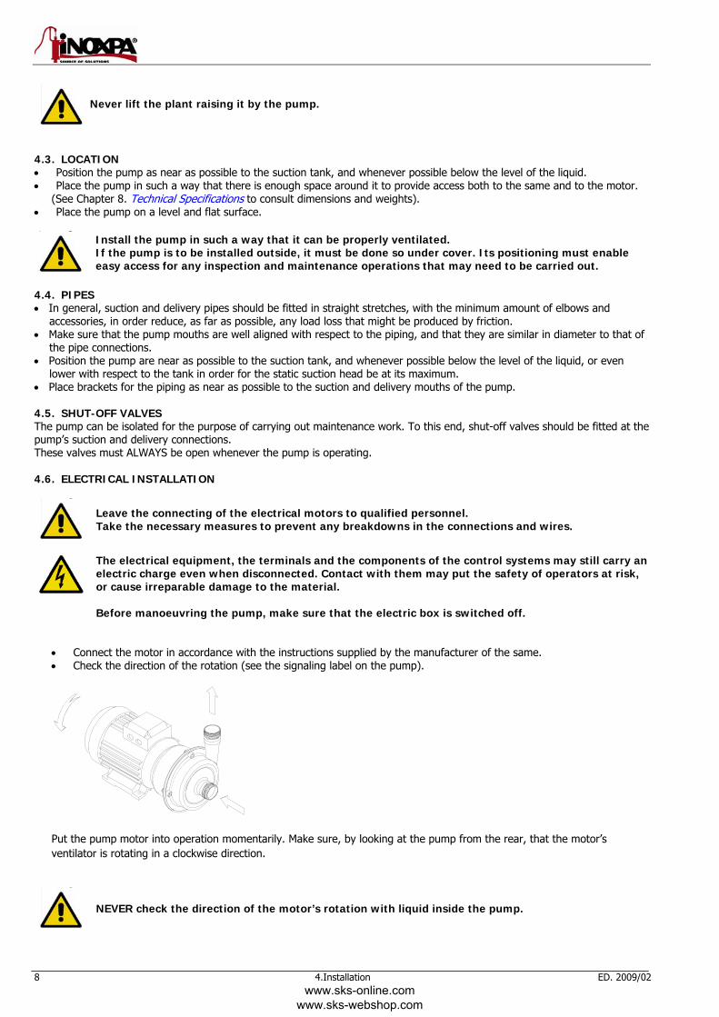
• Connect the motor in accordance with the instructions supplied by the manufacturer of the same. • Check the direction of the rotation (see the signaling label on the pump).
Put the pump motor into operation momentarily. Make sure, by looking at the pump from the rear, that the motor’s ventilator is rotating in a clockwise direction.
NEVER check the direction of the motor’s rotation with liquid inside the pump.
www.sks-online.com www.sks-webshop.com
ED. 2009/02 5.Start-up 9
5. Start-up
Before putting the pump into operation read carefully the instructions on installation given in Chapter 4. Installation.
5.1. START-UP
Read Chapter 8. Technical Specifications carefully. INOXPA will not assume responsibility for any improper or incorrect use of the equipment.
Do not touch the pump or the piping while it is pumping products at a high temperature.
5.1.1. Checks to be carried out before putting the pump into operation • Completely open the pipes’ suction and delivery shut-off valves. • If the liquid fails to flow toward the pump, fill it with the liquid to be pumped.
The pump must NEVER rotate without liquid.
• Check that the rotation direction of the motor is correct.
5.1.2. Checks to be carried out on putting the pump into operation • Check to make sure that the pump is not making any strange noises. • Check to see if the absolute inlet pressure is sufficient, in order to avoid cavitations in the pump. Consult the curve for the
minimum required pressure above the steam pressure (NPIPr). • Monitor the delivery pressure. • Check that there are no leaks in the sealed areas.
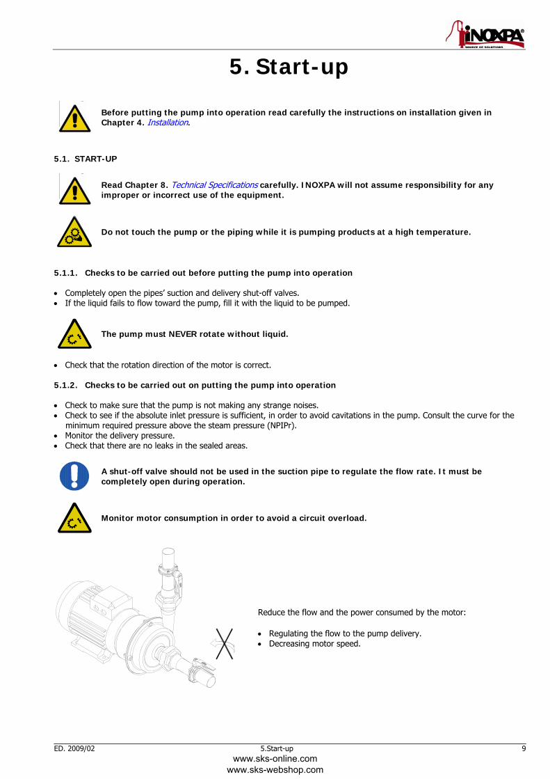
A shut-off valve should not be used in the suction pipe to regulate the flow rate. It must be completely open during operation.
Monitor motor consumption in order to avoid a circuit overload.
Reduce the flow and the power consumed by the motor: • Regulating the flow to the pump delivery. • Decreasing motor speed.
www.sks-online.com www.sks-webshop.com
10 6.Operating problems ED. 2009/02
6. Operating problems
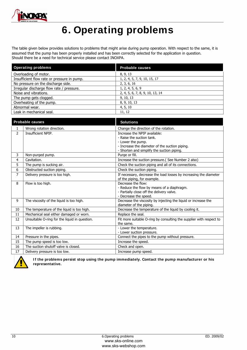
The table given below provides solutions to problems that might arise during pump operation. With respect to the same, it is assumed that the pump has been properly installed and has been correctly selected for the application in question. Should there be a need for technical service please contact INOXPA.
Operating problems Probable causes
Overloading of motor. 8, 9, 13 Insufficient flow rate or pressure in pump. 1, 2, 4, 5, 7, 9, 10, 15, 17 No pressure on the discharge side. 2, 3, 6, 16 Irregular discharge flow rate / pressure. 1, 2, 4, 5, 6, 9 Noise and vibrations. 2, 4, 5, 6, 7, 8, 9, 10, 13, 14 The pump gets clogged. 9, 10, 13 Overheating of the pump. 8, 9, 10, 13 Abnormal wear. 4, 5, 10 Leak in mechanical seal. 11, 12
Probable causes Solutions
1 Wrong rotation direction. Change the direction of the rotation. 2 Insufficient NPIP. Increase the NPIP available:
- Raise the suction tank. - Lower the pump. - Increase the diameter of the suction piping. - Shorten and simplify the suction piping.
3 Non-purged pump. Purge or fill.4 Cavitation. Increase the suction pressure.( See Number 2 also) 5 The pump is sucking air. Check the suction piping and all of its connections. 6 Obstructed suction piping. Check the suction piping.7 Delivery pressure is too high. If necessary, decrease the load losses by increasing the diameter
of the piping, for example. 8 Flow is too high. Decrease the flow:
- Reduce the flow by means of a diaphragm. - Partially close off the delivery valve. - Decrease the speed.
9 The viscosity of the liquid is too high. Decrease the viscosity by injecting the liquid or increase the diameter of the piping.
10 The temperature of the liquid is too high. Decrease the temperature of the liquid by cooling it. 11 Mechanical seal either damaged or worn. Replace the seal.12 Unsuitable O-ring for the liquid in question. Fit more suitable O-ring by consulting the supplier with respect to
the same. 13 The impeller is rubbing. - Lower the temperature.
- Lower suction pressure. 14 Pressure in the pipes. Connect the pipes to the pump without pressure. 15 The pump speed is too low. Increase the speed.16 The suction shutoff valve is closed. Check and open.17 Delivery pressure is too low. Increase pump speed.
If the problems persist stop using the pump immediately. Contact the pump manufacturer or his representative.
www.sks-online.com www.sks-webshop.com
ED. 2009/02 7.Maintenance 11
7. Maintenance 7.1. GENERAL MAINTENANCE This pump, as with any other machine, needs to be maintained. The instructions contained in this manual deal with the identification and replacement of the spare parts. These instructions have been drawn up by maintenance staff and are destined for those people who are responsible for supplying spare parts.
Read carefully Chapter 8. Technical specifications. All the parts or materials that are changed must be duly eliminated/recycled in accordance with the prevailing directives in each area.
ALWAYS disconnect the pump before starting out on any maintenance work.
7.1.1. Check the mechanical seal Periodically check that there are no leaks in the shaft area. Should there be any leaks in the mechanical seal area, replace the same pursuant to the instructions given in the section entitled Stripping and Assembly of the pump. 7.2. STORAGE Before being stored the pump must be completely emptied of liquids. Avoid, as far as possible, the exposure of the parts to excessively damp atmospheres. 7.3. CLEANING
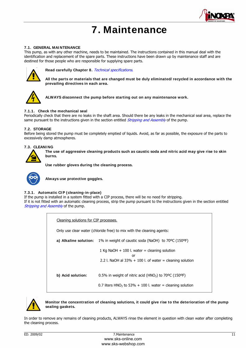
The use of aggressive cleaning products such as caustic soda and nitric acid may give rise to skin burns. Use rubber gloves during the cleaning process.
Always use protective goggles.
7.3.1. Automatic CIP (cleaning-in-place) If the pump is installed in a system fitted with a CIP process, there will be no need for stripping. If it is not fitted with an automatic cleaning process, strip the pump pursuant to the instructions given in the section entitled Stripping and Assembly of the pump.
Cleaning solutions for CIP processes. Only use clear water (chloride free) to mix with the cleaning agents: a) Alkaline solution: 1% in weight of caustic soda (NaOH) to 70ºC (150ºF) 1 Kg NaOH + 100 l. water = cleaning solution
or 2.2 l. NaOH al 33% + 100 l. of water = cleaning solution
b) Acid solution: 0.5% in weight of nitric acid (HNO3) to 70ºC (150ºF)
0.7 liters HNO3 to 53% + 100 l. water = cleaning solution
Monitor the concentration of cleaning solutions, it could give rise to the deterioration of the pump sealing gaskets.
In order to remove any remains of cleaning products, ALWAYS rinse the element in question with clean water after completing the cleaning process.
www.sks-online.com www.sks-webshop.com
12 7.Maintenance ED. 2009/02
7.3.2. Automatic SIP (sterilization-in-place) The process of sterilization with steam is applied to all the equipment including the pump.
Do NOT start the pump during the process of sterilization with steam. The parts/materials suffer no damage if the indications specified in this manual are observed. No cold liquid can enter the pump till the temperature of the pump is lower than 60°C (140°F). A flow by-pass is recommended to be used in order to assure the flow of sterile product after the pump.
Maximum conditions during the SIP process with steam or overheated water a) Max. temperature: 140°C / 284°F b) Max. time: 30 min c) Cooling: Sterile air or inert gas d) Materials: EPDM / PTFE (recommended) FPM / NBR (not recommended)
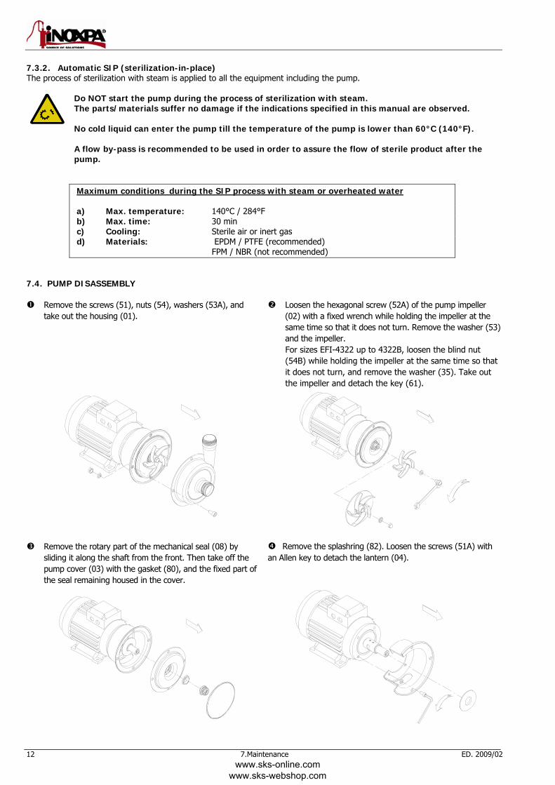
7.4. PUMP DISASSEMBLY
Remove the screws (51), nuts (54), washers (53A), and take out the housing (01).
Loosen the hexagonal screw (52A) of the pump impeller (02) with a fixed wrench while holding the impeller at the same time so that it does not turn. Remove the washer (53) and the impeller. For sizes EFI-4322 up to 4322B, loosen the blind nut (54B) while holding the impeller at the same time so that it does not turn, and remove the washer (35). Take out the impeller and detach the key (61).
Remove the rotary part of the mechanical seal (08) by sliding it along the shaft from the front. Then take off the pump cover (03) with the gasket (80), and the fixed part of the seal remaining housed in the cover.
Remove the splashring (82). Loosen the screws (51A) with an Allen key to detach the lantern (04).
www.sks-online.com www.sks-webshop.com
ED. 2009/02 7.Maintenance 13
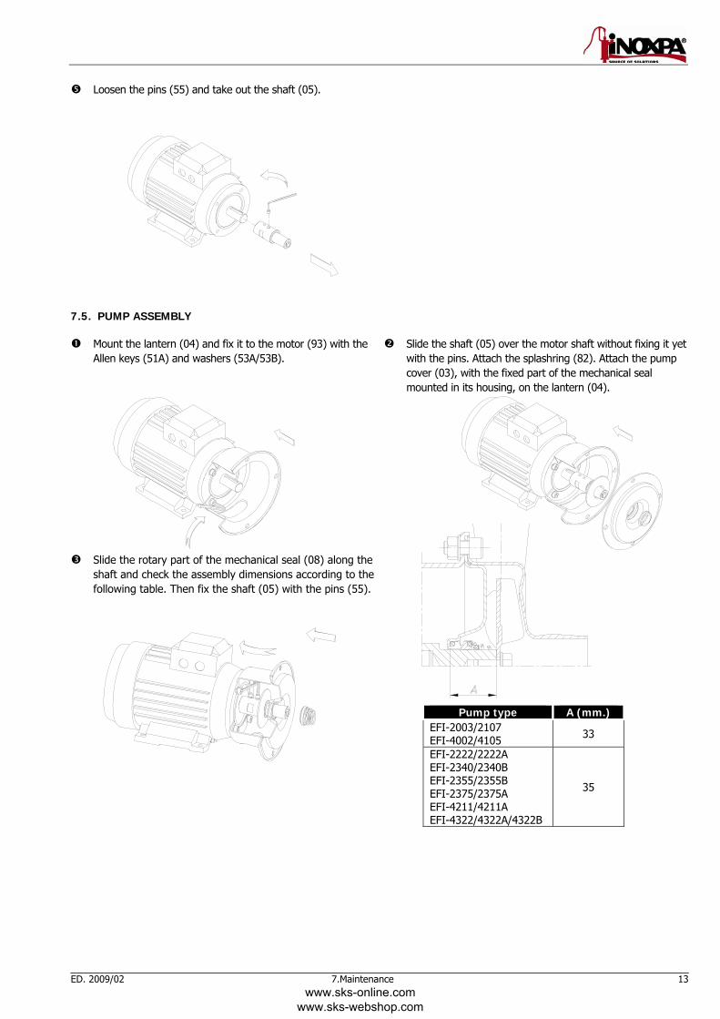
Loosen the pins (55) and take out the shaft (05).
7.5. PUMP ASSEMBLY
Mount the lantern (04) and fix it to the motor (93) with the Allen keys (51A) and washers (53A/53B).
Slide the shaft (05) over the motor shaft without fixing it yet with the pins. Attach the splashring (82). Attach the pump cover (03), with the fixed part of the mechanical seal mounted in its housing, on the lantern (04).
Slide the rotary part of the mechanical seal (08) along the shaft and check the assembly dimensions according to the following table. Then fix the shaft (05) with the pins (55).
Pump type A (mm.) EFI-2003/2107 EFI-4002/4105 33
EFI-2222/2222A EFI-2340/2340B EFI-2355/2355B EFI-2375/2375A EFI-4211/4211A EFI-4322/4322A/4322B
35
www.sks-online.com www.sks-webshop.com
14 7.Maintenance ED. 2009/02
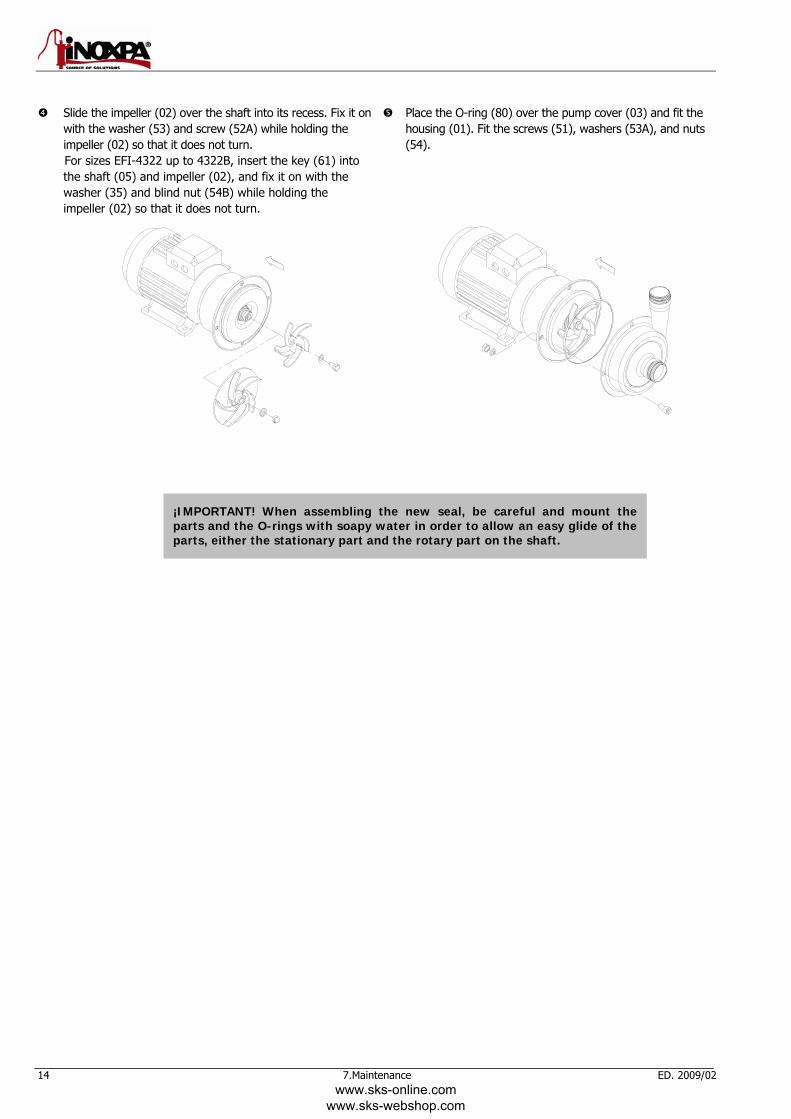
Slide the impeller (02) over the shaft into its recess. Fix it on with the washer (53) and screw (52A) while holding the impeller (02) so that it does not turn. For sizes EFI-4322 up to 4322B, insert the key (61) into the shaft (05) and impeller (02), and fix it on with the washer (35) and blind nut (54B) while holding the impeller (02) so that it does not turn.
Place the O-ring (80) over the pump cover (03) and fit the housing (01). Fit the screws (51), washers (53A), and nuts (54).
¡IMPORTANT! When assembling the new seal, be careful and mount the parts and the O-rings with soapy water in order to allow an easy glide of the parts, either the stationary part and the rotary part on the shaft.
www.sks-online.com www.sks-webshop.com
ED. 2009/02 8.Technical Specifications 15
8. Technical Specifications 8.1. TECHNICAL SPECIFICATIONS
Maximum suction pressure ...................................................... 2 bar (29 PSI) Maximum temperature ........................................................... -10 ºC a +90ºC (NBR)
14 ºF a 194 ºF (NBR) Noise level ............................................................................ 60-80 dB(A) Suction / delivery connections ................................................. GAS (BSP) (estándar)
Whenever the noise level in the area of operation exceeds 85 dB(A) use special protection.
Materials Parts in contact with the product ............................................... AISI 316L Other parts in stainless steel ..................................................... AISI 304 Gaskets and joints in contact with the product ........................... EPDM and Silicone (standard) Other optional joints materials .................................................. Consult your supplier Surface finish .......................................................................... Ra 0,8 Mechanical seal Seal type ............................................................................... . Single internal mechanical seal Stationary part material ........................................................... . Ceramic (standard) Rotary part material ................................................................ . Graphite (standard) Gaskets material ..................................................................... . NBR (standard)
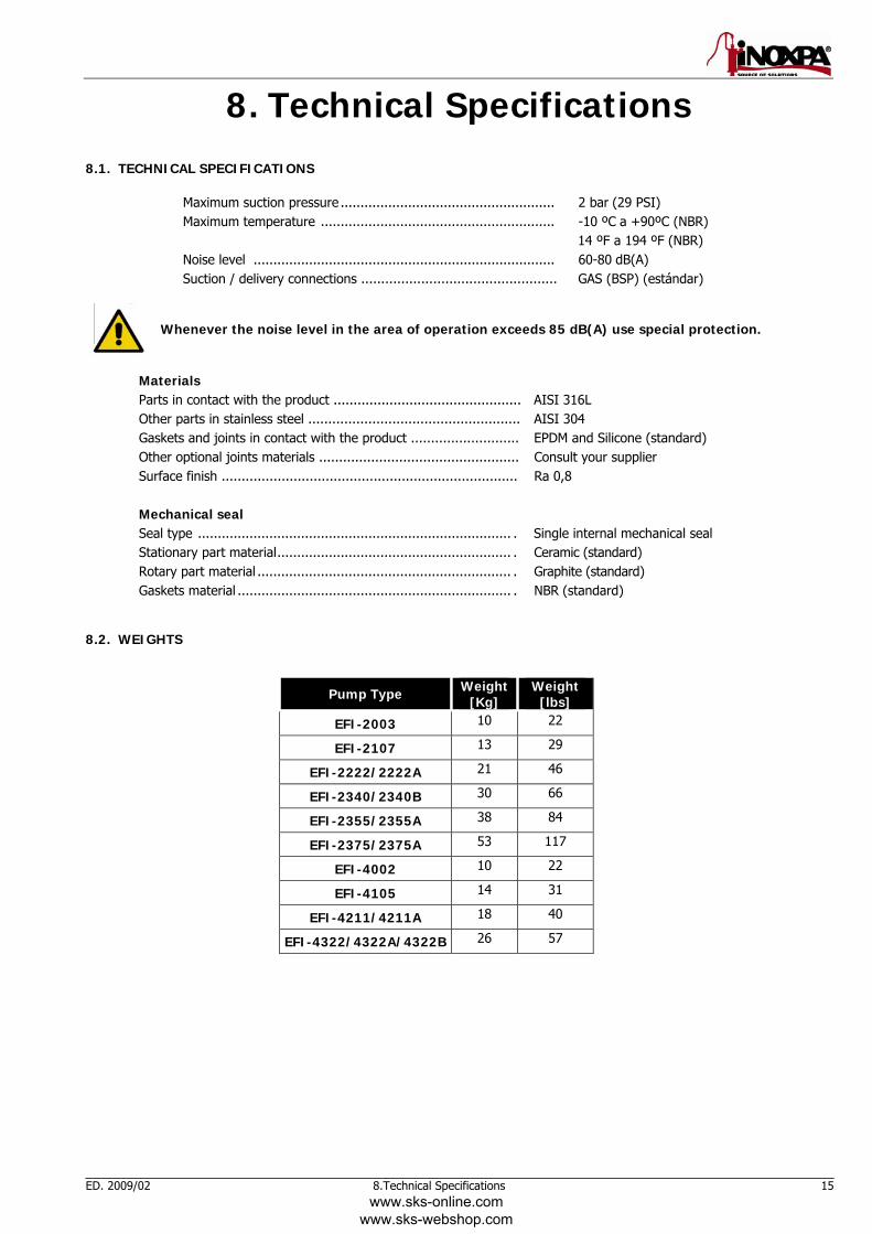
8.2. WEIGHTS
Pump Type Weight[Kg]
Weight [lbs]
EFI-2003 10 22
EFI-2107 13 29
EFI-2222/2222A 21 46
EFI-2340/2340B 30 66
EFI-2355/2355A 38 84
EFI-2375/2375A 53 117
EFI-4002 10 22
EFI-4105 14 31
EFI-4211/4211A 18 40
EFI-4322/4322A/4322B 26 57
www.sks-online.com www.sks-webshop.com
16 8.Technical Specifications ED. 2009/02
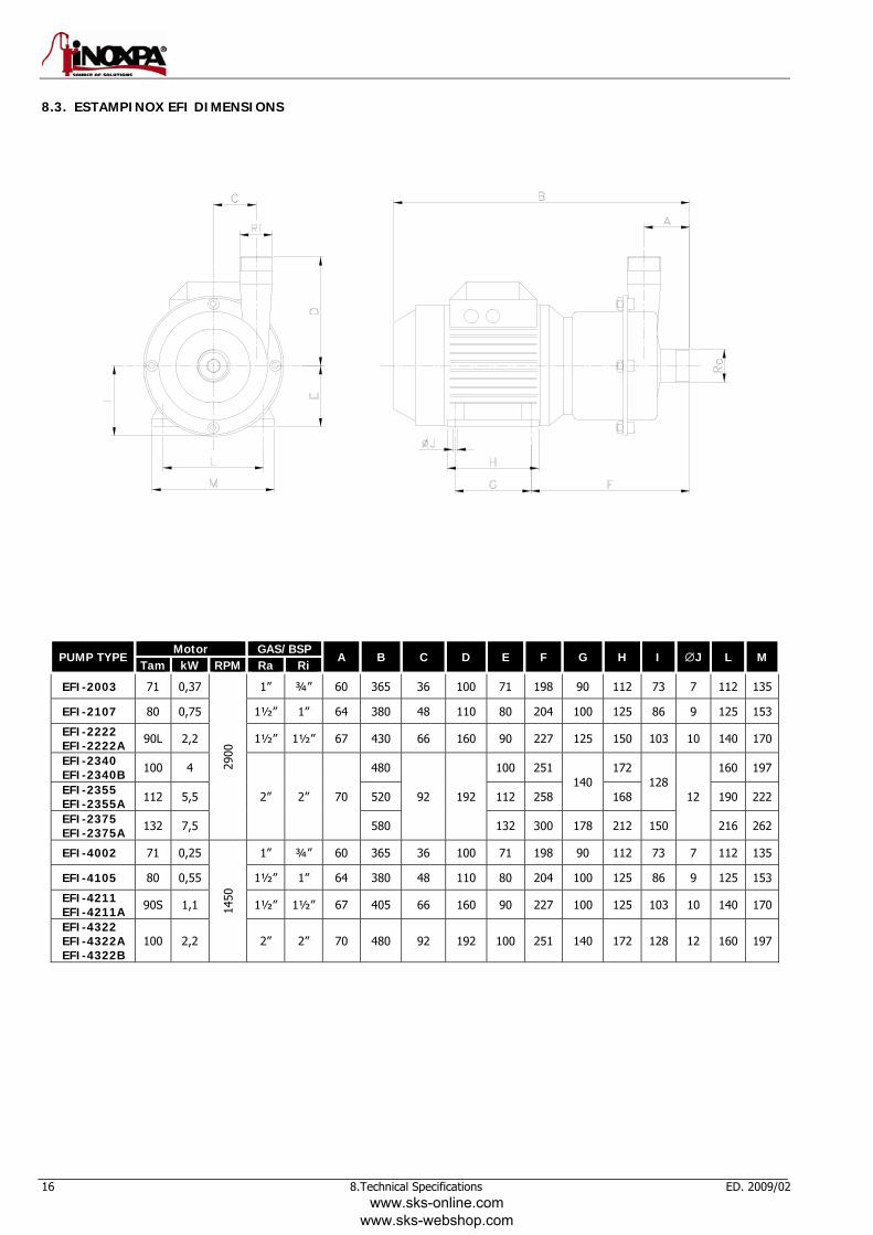
8.3. ESTAMPINOX EFI DIMENSIONS
PUMP TYPE Motor GAS/BSP
A B C D E F G H I ∅J L M Tam kW RPM Ra Ri
EFI-2003 71 0,37
2900
1” ¾” 60 365 36 100 71 198 90 112 73 7 112 135
EFI-2107 80 0,75 1½” 1” 64 380 48 110 80 204 100 125 86 9 125 153
EFI-2222 EFI-2222A 90L 2,2 1½” 1½” 67 430 66 160 90 227 125 150 103 10 140 170
EFI-2340 EFI-2340B 100 4
2” 2” 70
480
92 192
100 251 140
172 128
12
160 197
EFI-2355 EFI-2355A 112 5,5 520 112 258 168 190 222
EFI-2375 EFI-2375A 132 7,5 580 132 300 178 212 150 216 262
EFI-4002 71 0,25
1450
1” ¾” 60 365 36 100 71 198 90 112 73 7 112 135
EFI-4105 80 0,55 1½” 1” 64 380 48 110 80 204 100 125 86 9 125 153
EFI-4211 EFI-4211A 90S 1,1 1½” 1½” 67 405 66 160 90 227 100 125 103 10 140 170
EFI-4322 EFI-4322A EFI-4322B
100 2,2 2” 2” 70 480 92 192 100 251 140 172 128 12 160 197
www.sks-online.com www.sks-webshop.com
ED. 2009/02 8.Technical Specifications 17
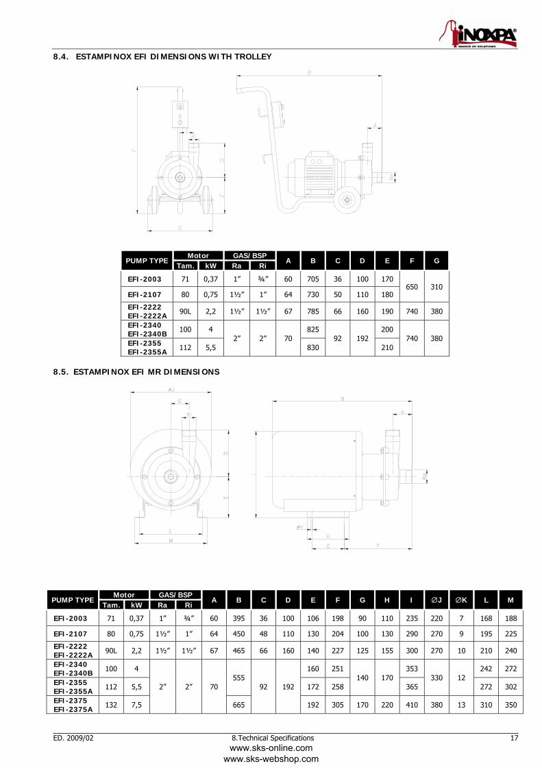
8.4. ESTAMPINOX EFI DIMENSIONS WITH TROLLEY
PUMP TYPE Motor GAS/BSP
A B C D E F G Tam. kW Ra Ri
EFI-2003 71 0,37 1” ¾” 60 705 36 100 170 650 310
EFI-2107 80 0,75 1½” 1” 64 730 50 110 180
EFI-2222 EFI-2222A 90L 2,2 1½” 1½” 67 785 66 160 190 740 380
EFI-2340 EFI-2340B 100 4
2” 2” 70 825
92 192 200
740 380 EFI-2355 EFI-2355A 112 5,5 830 210
8.5. ESTAMPINOX EFI MR DIMENSIONS
PUMP TYPE Motor GAS/BSP
A B C D E F G H I ∅J ∅K L M Tam. kW Ra Ri
EFI-2003 71 0,37 1” ¾” 60 395 36 100 106 198 90 110 235 220 7 168 188
EFI-2107 80 0,75 1½” 1” 64 450 48 110 130 204 100 130 290 270 9 195 225
EFI-2222 EFI-2222A 90L 2,2 1½” 1½” 67 465 66 160 140 227 125 155 300 270 10 210 240
EFI-2340 EFI-2340B 100 4
2” 2” 70 555
92 192
160 251 140 170
353 330 12
242 272
EFI-2355 EFI-2355A 112 5,5 172 258 365 272 302
EFI-2375 EFI-2375A 132 7,5 665 192 305 170 220 410 380 13 310 350
www.sks-online.com www.sks-webshop.com
18 8.Technical Specifications ED. 2009/02
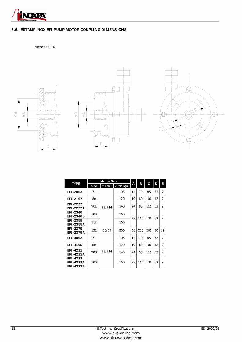
8.6. ESTAMPINOX EFI PUMP MOTOR COUPLING DIMENSIONS
Motor size 132
TYPE Motor Size
A B C D Esize model ∅ flange
EFI-2003 71
B3/B14
105 14 70 85 32 7
EFI-2107 80 120 19 80 100 42 7
EFI-2222 EFI-2222A 90L 140 24 95 115 52 9
EFI-2340 EFI-2340B 100 160
28 110 130 62 9 EFI-2355 EFI-2355A 112 160
EFI-2375 EFI-2375A 132 B3/B5 300 38 230 265 80 12
EFI-4002 71
B3/B14
105 14 70 85 32 7
EFI-4105 80 120 19 80 100 42 7
EFI-4211 EFI-4211A 90S 140 24 95 115 52 9
EFI-4322 EFI-4322A EFI-4322B
100 160 28 110 130 62 9
www.sks-online.com www.sks-webshop.com
ED. 2009/02 8.Technical Specifications 19
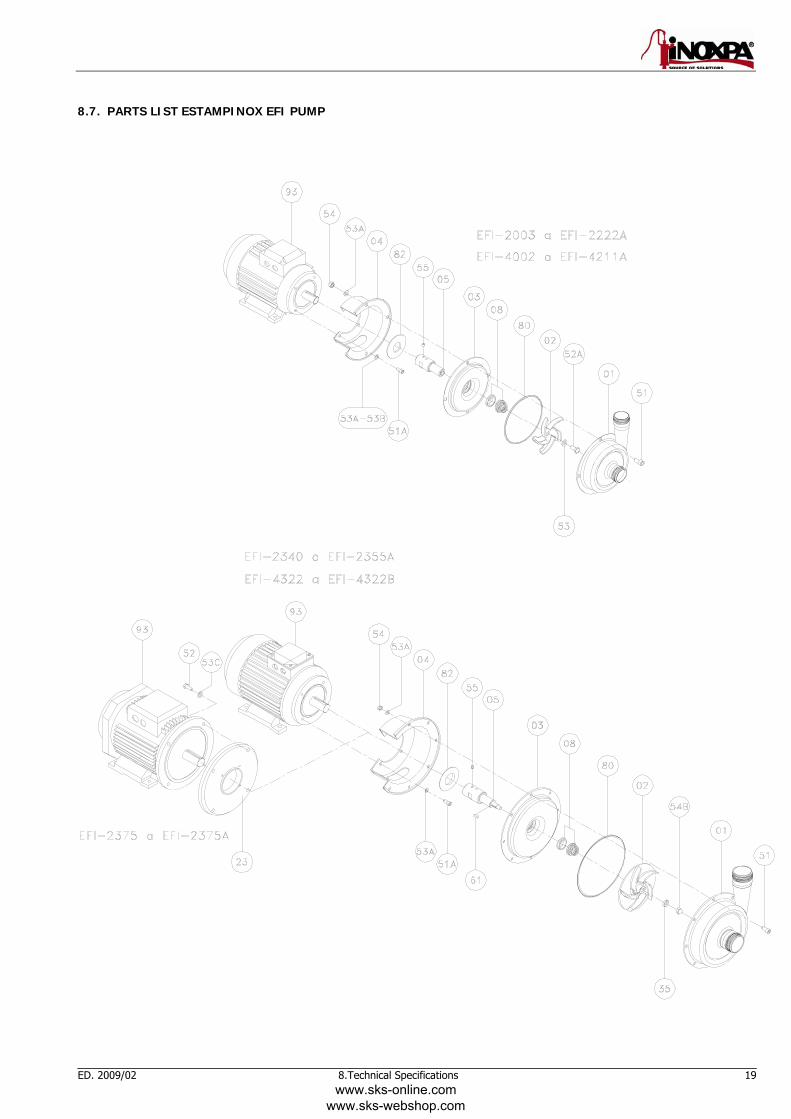
8.7. PARTS LIST ESTAMPINOX EFI PUMP
www.sks-online.com www.sks-webshop.com
20 8.Technical Specifications ED. 2009/02
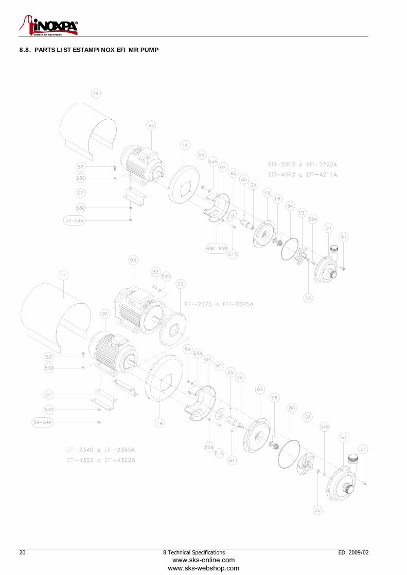
8.8. PARTS LIST ESTAMPINOX EFI MR PUMP
www.sks-online.com www.sks-webshop.com
ED. 2009/02 8.Technical Specifications 21
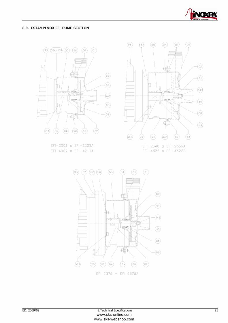
8.9. ESTAMPINOX EFI PUMP SECTION
www.sks-online.com www.sks-webshop.com
22 8.Technical Specifications ED. 2009/02
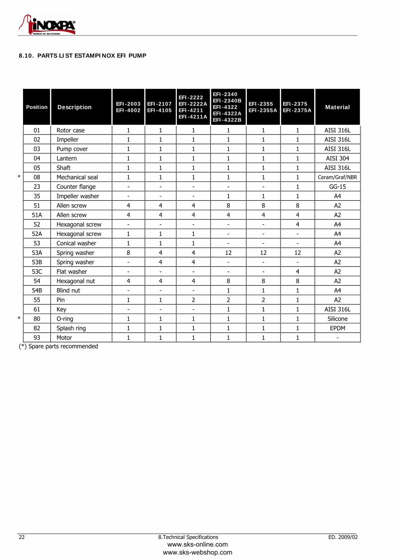
8.10. PARTS LIST ESTAMPINOX EFI PUMP
Position Description EFI-2003 EFI-4002
EFI-2107 EFI-4105
EFI-2222 EFI-2222A EFI-4211 EFI-4211A
EFI-2340 EFI-2340B EFI-4322 EFI-4322A EFI-4322B
EFI-2355 EFI-2355A
EFI-2375 EFI-2375A Material
01 Rotor case 1 1 1 1 1 1 AISI 316L 02 Impeller 1 1 1 1 1 1 AISI 316L
03 Pump cover 1 1 1 1 1 1 AISI 316L
04 Lantern 1 1 1 1 1 1 AISI 304
05 Shaft 1 1 1 1 1 1 AISI 316L
* 08 Mechanical seal 1 1 1 1 1 1 Ceram/Graf/NBR
23 Counter flange - - - - - 1 GG-15
35 Impeller washer - - - 1 1 1 A4
51 Allen screw 4 4 4 8 8 8 A2
51A Allen screw 4 4 4 4 4 4 A2
52 Hexagonal screw - - - - - 4 A4
52A Hexagonal screw 1 1 1 - - - A4
53 Conical washer 1 1 1 - - - A4
53A Spring washer 8 4 4 12 12 12 A2
53B Spring washer - 4 4 - - - A2
53C Flat washer - - - - - 4 A2
54 Hexagonal nut 4 4 4 8 8 8 A2
54B Blind nut - - - 1 1 1 A4
55 Pin 1 1 2 2 2 1 A2
61 Key - - - 1 1 1 AISI 316L
* 80 O-ring 1 1 1 1 1 1 Silicone
82 Splash ring 1 1 1 1 1 1 EPDM
93 Motor 1 1 1 1 1 1 - (*) Spare parts recommended
www.sks-online.com www.sks-webshop.com
ED. 2009/02 8.Technical Specifications 23
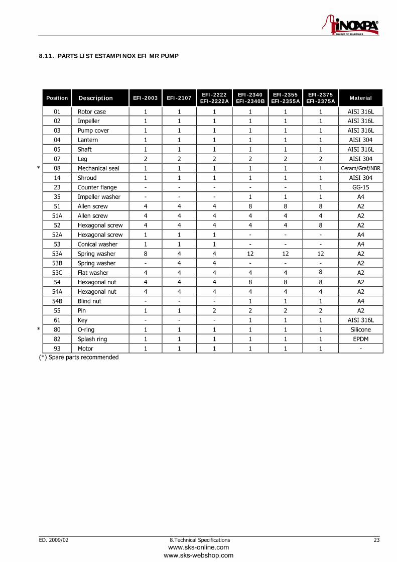
8.11. PARTS LIST ESTAMPINOX EFI MR PUMP
Position Description EFI-2003 EFI-2107 EFI-2222 EFI-2222A
EFI-2340 EFI-2340B
EFI-2355 EFI-2355A
EFI-2375 EFI-2375A Material
01 Rotor case 1 1 1 1 1 1 AISI 316L 02 Impeller 1 1 1 1 1 1 AISI 316L
03 Pump cover 1 1 1 1 1 1 AISI 316L
04 Lantern 1 1 1 1 1 1 AISI 304
05 Shaft 1 1 1 1 1 1 AISI 316L
07 Leg 2 2 2 2 2 2 AISI 304
* 08 Mechanical seal 1 1 1 1 1 1 Ceram/Graf/NBR
14 Shroud 1 1 1 1 1 1 AISI 304
23 Counter flange - - - - - 1 GG-15
35 Impeller washer - - - 1 1 1 A4
51 Allen screw 4 4 4 8 8 8 A2
51A Allen screw 4 4 4 4 4 4 A2
52 Hexagonal screw 4 4 4 4 4 8 A2
52A Hexagonal screw 1 1 1 - - - A4
53 Conical washer 1 1 1 - - - A4
53A Spring washer 8 4 4 12 12 12 A2
53B Spring washer - 4 4 - - - A2
53C Flat washer 4 4 4 4 4 8 A2
54 Hexagonal nut 4 4 4 8 8 8 A2
54A Hexagonal nut 4 4 4 4 4 4 A2
54B Blind nut - - - 1 1 1 A4
55 Pin 1 1 2 2 2 2 A2
61 Key - - - 1 1 1 AISI 316L
* 80 O-ring 1 1 1 1 1 1 Silicone
82 Splash ring 1 1 1 1 1 1 EPDM
93 Motor 1 1 1 1 1 1 - (*) Spare parts recommended
www.sks-online.com www.sks-webshop.com
INOXPA, S.A. c/ Telers, 57 – PO Box 174 17820 BANYOLES – GIRONA www.inoxpa.com Tel: +34 972 575 200 SPAIN e-mail: [email protected] Fax: +34 972 575 502 BARCELONA – FLUAL, S.L. MADRID – INOXFLUID, S.L BILBAO – STA, S.L. Tel: 937 297 280 Tel: 918 716 084 Tel: 944 572 058 e-mail: [email protected] e-mail: [email protected] e-mail: [email protected] VALENCIA – INOXDIN, S.L. VALLADOLID – ALTAFLUID, S.L. CÁDIZ – CORFLUID, S.L. Tel: 963 170 101 Tel: 983 403 197 Tel: 956 140 193 e-mail: [email protected] e-mail: [email protected] e-mail: [email protected] ZARAGOZA – FLUAL, S.L. LA RIOJA – STA, S.L. SEVILLA – CORFLUID, S.L. Tel: 976 591 942 Tel: 941 228 622 Tel: 954 296 852 e-mail: [email protected] e-mail: [email protected] e-mail: [email protected] CÓRDOBA – CORFLUID, S.L. LA MANCHA – INOXFLUID, S.L. ASTURIAS – STA, S.L. Tel: 957 169 145 Tel: 926 514 190 Tel: 985 267 553 e-mail: [email protected] e-mail: [email protected] e-mail: [email protected] INOXPA FRANCE, S.A. - AGENCE NORD AGENCE LYON Z.A.C. D’EPINAY AGENCE SUD 2, Avenue Saint Pierre 69 Allée des Caillotières Route d’Olonzac59118 WAMBRECHIES (France) GLEIZE 69400 (France) 11200 HOMPS (France) Tél: 33(0)320 631000 Tél: 33(0)474 627100 Tél: 33(0)468 278680 Fax: 33(0)320 631001 Fax: 33(0)474 627101 Fax: 33(0)468 278681 e-mail: [email protected] e-mail: [email protected] e-mail: [email protected] AGENCE OUEST INOXPA SOLUTIONS FRANCE INOXPA ITALIA S.R.L. ZA des Roitelières Rue Henri Becquerel Via Olivetti, s.n.c., Z.I. 44330 LE PALLET (France) F - 60230 CHAMBLY (France) 26010 VAIANO CREMASCO - Cr - (Italia) Tél: 33(0)228 010172 Tél: 33(0)130289100 Tel: 39(0)373 791076 Fax: 33(0)228 010173 Fax: 33(0)130289101 Fax: 39(0)373 791113 e-mail: [email protected] e-mail: [email protected] e-mail: [email protected] INOXPA SWEDEN INOXPA SKANDINAVIEN A/S INOXPA SOUTH AFRICA (PTY) LTD Laxfiskevägen 12 H∅egh Guldbergsgade 27 HEAD OFFICE (PTY) Ltd. SE-43338 PARTILLE (Sweden) HORSENS DK-8700 (Denmark) Unit 4 Production Park, Epsom Ave Tel: 46 (0) 31 336 05 60 Tel: (45) 76 28 69 00 NORTHLANDS – NORTHRIDING Fax: 46 (0 )31 336 05 61 Fax: (45) 76 28 69 09 JOHANNESBURG – SOUTH AFRICA e-mail: [email protected] e-mail: [email protected] PO Box 1464, Olivedale, 2158 Tel: 011-796-5170 S.T.A. PORTUGUESA LDA. INOXPA POLAND sp z o.o. Fax: 086-680-7756 Zona Industrial - Lugar do Guardal Ul. Arkonska, 54 e-mail: [email protected] ALGERIZ. 3730-266 VALE DE CAMBRA 80-392 Gdansk (Poland) (Portugal) Tel. 48 58 511 00 05 INOXRUS Ltd. Tel: 351 256 472722 Fax: 48 58 556 72 51 194292, Saint Petersburg Fax: 351 256 425697 e-mail: [email protected] Industrial Area ‘Parnas’ e-mail: [email protected] Ulitsa Domostroitelnaya 4, office 310 Тел.: 7 812 622 16 26 INOXPA DEUTSCHLAND GMBH INOXPA USA, Inc Fax: 7 812 622 19 26 Kohlhammerstrasse, 6 3715 Santa Rosa Avenue Suite A4 e-mail: [email protected] D - 70771 LEINFELDEN Santa Rosa, CA95407 DEUTSCHLAND (California) INOXRUS Ltd. Tel: 49 (0) 711 758 59 73 Tel: 1 707 585 3900 ОСК Мидланд, офис 11 Fax: 49 (0) 711 758 59 750 Fax: 1 707 585 3908 Химкинский район, квартал Клязьма e-mail: [email protected] e-mail: [email protected] 141400 Москва Тел.: 495 223 04 11 INOXPA REALM Ltd. BOMBAS IMCHISA, S.A e-mail: [email protected] 15, Omrside Way – Holmethorpe State Calle dos, nº 9447 REDHILL – SURREY RH1 2QA QUILICURA – SANTIAGO de CHILE Tel: 44 2086895521 Tel: 56-2-7266945/6 Fax: 44 2086890245 e-mail: [email protected] e-mail: [email protected]
INOXPA products are available from our branch offices and through a network of independent distributors covering more than 50 countries around the World. For more information, visit our Web site: www.inoxpa.com This information is given for guidance only. We reserve the right to change any materials or characteristics without prior notice.
www.sks-online.com www.sks-webshop.com