Embed Size (px)
Citation preview

ISP No: pf dewatering - 12/16
INSTALLATION, SERVICE & PARTS MANUAL
Power-Flo Pumps & Systems • 877-24PUMPS • www.powerflopumps.com
PF Dewatering SeriesSubmersible Dewatering Pumps

Power-Flo Pumps & Systems • 877-24PUMPS • www.powerflopumps.com
Page # ®
2
Safety Instructions 3
Power-Flo Model Listing 4
Pump Specifications 4-5
Pump Dimensions 6-7
General Information 8
Installation & Operation 8-9
Preventive Maintenance 9
Service and Repair 10-15
Troubleshooting 16
Drawings & Parts List 17-31
Hardware Parts List 32
Pump Component Drawings for Series:PF01000 Series - 3/4 hp modelsPF01300 Series - 1 hp modelsPF20000 Series - 2 hp modelsPF25000 Series - 2-1/2 hp modelsPF27000 Series - 2-3/4 hp modelsPF35000 Series - 3-1/2 hp modelsPF50000 Series - 5 hp modelsPF60000 Series - 6 hp modelsPF81000 Series - 10 hp modelsPF81500 Series - 15 hp modelsPF82500 Series - 25 hp models
PF85000 Series - 50 hp models
Control Box Component Drawings:Control Wiring Diagram Page 33 - 35
® Power-Flo is a registered trademark of Power-Flo Technologies Inc.Other brand and product names are trademarks or registered trademarks of their respective holders.Alteration Rights Reserved; 1/09, 6/16, 10/16, 12/16
PF Series Submersible Dewatering Pumps
Contents
Model Number PF50112
MFG Date 02-07
Voltage 230v Phase 1.0
60 Hz HP 5.0877-24 PUMPS
www.powerflopumps.com
Pump Model Number: _____________________________________
Serial Number or MFG Date: ________________________________
Date of Purchase: _________________________________________
Installation Date: __________________________________________
Voltage and Current Readings at Startup:
1-Phase Models: 3-Phase Models:
Amps ______________ Amps L1-2 ________________ Volts L1-2 _________________
Volts _______________ Amps L2-3 ________________ Volts L2-3 _________________
Amps L3-1 ________________ Volts L3-1 _________________
Typical Name Plate
MC

Power-Flo Pumps & Systems • 877-24PUMPS • www.powerflopumps.com
®
3Page #
THOROUGHLY REVIEW ALL INSTRUCTIONS BEFORE INSTALLING, OPERATING OR PERFORMING ANY WORK ON THIS PUMP.
FOR YOUR SAFTEY AND THE SAFETY OF OTHERS -This manual is intended to assist in the installation and operation of the pump and should be kept for easy reference at all times. Please pay particular attention to the SAFETY ALERT messages throughout this manual.
IMPORTANT! Information or directions related to assembly, installation, operation, or maintenance which could result in personal injury or damage to the pump or system if ignored.
WARNING! Warns of hazards that CAN or WILL cause serious personal injury, death, or major property damage if ignored.
WARNING! Only qualified personnel should install, operate and repair pump. All electrical work must be performed by a qualified electrician. To reduce the risk of electrical shock, all wiring, junction connections
and control panels must be properly wired and grounded in accordance with the National Electric Code (NEC) or the Canadian Electrical Code (CEC) and all applicable state, province, local codes and ordinances. Failure to follow these codes may result in personal injury or equipment damage and will void the warranty.
WARNING! This pump is NOT intended for use in swimming pools. When used in a decorative fountain application the pump MUST be protected by a Ground Fault Interrupter.
WARNING! This pump is NOT intended for applications including hazardous materials or where flammable gases exist. Only pumps specifically Listed for Class 1, Division 1 are allowable where hazardous liquids or flammable gases may exist.
IMPORTANT! Failure to follow the instructions in this manual may lead to serious injury or even death! The following safety guidelines should be followed when operating any submersible pump.
• NEVER operate the pump without proper protective safety glasses, steel-toed boots and/or other protective devices required for the job.
• ALWAYS disconnect the pump from the power source before handling or servicing. Lock out and tag the power supply to reduce risk of electrical shock.
• ALWAYS make sure the pump is grounded properly. Improper grounding may void the warranty.
• NEVER operate a pump with a plug-in type power cord without a ground fault interrupter.
• NEVER plug in the pump while standing in water.
• ALWAYS protect the power cable to avoid punctures, cut, bruises and abrasions - inspect frequently.
• ALWAYS make sure that the voltage supplied to the pump is correct. Check the pump name plate to verify the required voltage.
• CAUTION! The pump may build up heat and pressure during operation. Allow time for the pump to cool before handling or servicing.
• DO NOT lift the pump by the power cord. The use of an adequate rope or lifting chain should be attached to the lifting handles. Make sure that the lifting handles are securely fastened each time before lifting
• DO NOT wear loose clothing that may become entangled in the impeller or other moving parts.
• DO NOT insert fingers into the pump while power is connected and the pump is running.
• DO NOT exceed manufacturers recommendation for maximum performance or temperature, as this could cause the motor to overheat or damage to the unit.
WARNING! Products returned must be cleaned, sanitized, or decontaminated as necessary prior to shipment, to insure that employees will not be exposed to health
hazards in handling said material. Return of merchandise requires “RMA” (Return Merchandise Authorization). Contact factory or pump supplier for authorization. All applicable laws and regulations shall apply.
Bronze/brass and bronze/brass fitted pumps may contain lead levels higher than considered safe for potable water systems. Lead is known to cause cancer and birth
defects or other reproductive harm. Various government agencies have determined that leaded copper alloys should not be used in potable water applications. For non-leaded copper alloy materials of construction, please contact factory.
IMPORTANT! Power-Flo Pumps & Systems is not responsible for losses, injury, or death resulting from a failure to observe these safety precautions, misuse or abuse of pumps or equipment.
General Safety Instructions
PF Series Submersible Dewatering Pumps

Power-Flo Pumps & Systems • 877-24PUMPS • www.powerflopumps.com
Page # ®
4
Model Motor HP
RPM Volt/ Phase
Shut Off
Head
Max FlowGPM
Dischg Full Load Amps
Locked Rotor Amps
Cord Size
Cord O.D.
Winding Resistance
W,B--R,B--R,WPF01011 3/4 3450 115/1 41’ 100 2” 11.0 36.2 14/4 0.570 1.5-6.2-4.7PF01034 3/4 3450 460/3 41’ 100 2” 1.8 7.5 14/4 0.570 34.2-34.2-34.2PF01012 3/4 3450 230/1 41’ 100 2” 5.8 18.1 14/4 0.570 6.0-7.6-7.6PF01032 3/4 3450 230/3 41’ 100 2” 3.6 15.0 14/4 0.570 8.5-8.5-8.5PF01311 ‡ 1 3450 115/1 43’ 120 2” 12.0 36.2 14/4 0.570 1.5-6.2-4.7PF01311A 1 3450 115/1 46’ 120 2” 12.0 36.2 14/4 0.570 1.5-6.2-4.7PF01311SCV 1 3450 115/1 46’ 120 2” 12.0 36.0 14/3 0.570 1.5-6.2-4.7PF01312 ‡ 1 3450 230/1 43’ 120 2” 7.5 18.0 14/4 0.570 6.0-7.6-7.6PF01332 ‡ 1 3450 230/3 43’ 120 2” 3.8 15.0 14/4 0.570 8.5-8.5-8.5PF01334 ‡ 1 3450 460/3 43’ 120 2” 1.9 7.5 14/4 0.570 34.2-34.2-34.2PF20111 2 3450 115/1 76’ 175 2” & 3” 23.3 92.4 12/4 0.650 0.4-1.5-1.1PF20112 2 3450 230/1 76’ 175 2” & 3” 11.7 51.1 12/4 0.650 1.6-5.8-4.2PF25132HH 2-1/2 3450 230/3 89’ 152 2” & 3” 6.8 49.2 12/4 0.650 2.0-2.0-2.0PF25132HV 2-1/2 3450 230/3 50’ 300 2” & 3” 7.8 49.2 12/4 0.650 2.0-2.0-2.0PF25134HH 2-1/2 3450 460/3 89’ 152 2” & 3” 3.4 24.6 12/4 0.650 8.0-8.0-8.0PF25134HV 2-1/2 3450 460/3 50’ 300 2” & 3” 3.9 24.6 12/4 0.650 8.0-8.0-8.0PF27112 2-3/4 3450 230/1 50’ 300 2” & 3” 12.5 52.6 12/4 0.650 1.60-5.80-4.20PF35112 3-1/2 3450 230/1 78’ 250 2” & 3” 18.5 84.1 12/4 0.650 0.86-2.2-2.2PF50112 5 3450 230/1 91’ 300 2” & 3” 27.0 94.0 12/4 0.650 0.7-2.7-2.0PF50132HV 5 3450 230/3 91’ 300 2” & 3” 15.5 87.8 12/4 0.650 0.85-0.85-0.85PF50134HV 5 3450 460/3 91’ 300 2” & 3” 7.8 43.9 12/4 0.650 3.60-3.60-3.60PF500135HV 5 3450 575/3 91’ 300 2” & 3” 6.1 35.1 12/4 0.650 5.2-5.2-5.2PF50132-2ST 5 3450 230/3 175’ 185 2” & 3” 17.3 98.0 12/4 0.650 0.85-0.85-0.85PF50134-2ST 5 3450 460/3 175’ 185 2” & 3” 8.7 48.0 12/4 0.650 3.60-3.60-3.60PF60112 6 3450 230/1 80’ 450 4” 34.0 145.0 6/4 1.100 0.43-1.8-1.37PF81032HH 10 3450 230/3 165’ 450 4” 30.0 208.0 6/4 1.100 0.30-0.30-0.30PF81032HV 10 3450 230/3 104’ 605 4” 30.0 208.0 6/4 1.100 0.30-0.30-0.30PF81034HH 10 3450 460/3 165’ 450 4” 15.0 104.0 12/4 0.650 1.14-1.14-1.14PF81034HV 10 3450 460/3 104’ 605 4” 15.0 104.0 12/4 0.650 1.14-1.14-1.14PF81532HH 15 3450 230/3 200’ 600 4” 39.5 288.0 6/4 1.100 0.21-0.21-0.21PF81532HV 15 3450 230/3 130’ 800 4” 39.5 288.0 6/4 1.100 0.21-0.21-0.21PF81534HH 15 3450 460/3 200’ 600 4” 19.7 144.0 12/4 0.650 0.75-0.75-0.75PF81534HV 15 3450 460/3 130’ 800 4” 19.7 144.0 12/4 0.650 0.75-0.75-0.75PF82532HH 25 3450 230/3 230’ 800 6” 65.8 464.0 4/4 1.286 0.37-0.37-0.37PF82532HV 25 3450 230/3 160’ 1000 6” 65.8 464.0 4/4 1.286 0.37-0.37-0.37PF82534HH 25 3450 460/3 230’ 800 6” 32.9 232.0 4/4 1.286 0.10-0.10-0.10PF82534HV 25 3450 460/3 160’ 1000 6” 32.9 232.0 4/4 1.286 0.10-0.10-0.10PF85034HH 50 3450 460/3 245’ 1025 6” 56.0 360.0 4/4 1.286 0.19-0.19-0.19PF85034HV 50 3450 460/3 190’ 1425 6” 56.0 360.0 4/4 1.286 0.19-0.19-0.19
Winding Resistance ± 5%. LC = Less Control Box. (‡ ) 1Hp pumps prior to Dec. 2009 (Mfg Date: MC) had a shut off head of 46Ft., After Dec. 2009 they will be 43Ft .
PF Series Submersible Dewatering Pumps
Pump Specifications

Power-Flo Pumps & Systems • 877-24PUMPS • www.powerflopumps.com
®
5Page #
LIQUID TEMPERATURE 140°F (60°C)
DISCHARGE CASE Aluminum, Hard Anodized
DIFFUSER Aluminum, Hard Anodized
SUCTION CASE Aluminum, Hard Anodized, with wear resistant polyurethane liner
FRAME Aluminum, Hard Anodized
OUTER CASE Aluminum, Hard Anodized
WEAR PLATE* Polyurethane
PUMP SHAFT Stainless Steel
IMPELLER Polyurethane (3/4hp & 1hp only)Stainless Steel (2hp - 50hp models)
HARDWARE Stainless Steel
O-RING MATERIAL Buna-N
SEAL Design Tandem, Oil Lubricated
INBOARD Material Rotating Face - CarbonStationary Face - CeramicElastomer - Buna-NHardware - 300 Series Stainless
OUTBOARD Material Rotating Face - Silicon CarbideStationary Face - Silicon CarbideElastomer - Buna-NHardware - 300 Series Stainless
STRAINER Stainless steel, 3/16” Holes on 3/4 & 1HP, 1/4” Holes on Rest
Anti-Sludge, Stainless Steel, 3/16” Holes on PF01311SCV, (Optional)
UPPER BEARING Design Single Row, Ball
Lubrication Prelubricated high-temperature grease
Load Radial
LOWER BEARING Design (.75hp-5hp) Single Row, Ball
Design (6, 10 & 15hp) Single Row, Ball, Shielded
Design (25hp-50hp) Double Row, Shielded, Ball, Angular contact
Lubrication (all models) Prelubricated high-temperature grease
Load (all models) Radial & Thrust
POWER CABLE 25 & 50Ft., with Strain Relief and Pressure Grommet for Sealing
POWER CABLE PF01311SCV - Only 65Ft, with Strain Relief and Pressure Grommet for Sealing, & 115 volt plug
MOTOR Insulation: Class H ~ VPI (vacuum Pressure Impregnation)
MOTOR PF01311SCV - Only Insulation: Class H ~ VPI, Overload protection included in motor. Internal start & run capcitors
CONTROL Single Phase Watertight. Provides overload and short circuit protection. Start & Run Capacitors, ON-OFF Switch
Three Phase Watertight. Provides Circuit Breaker for overload and short circuit protection
(*) Not used on 3/4 and 1HP units. WARRANTY INVALID IF CORRECT POWER-FLO CONTROL IS NOT USED AT ALL TIMES
PF Series Submersible Dewatering Pumps
Pump Specifications

Power-Flo Pumps & Systems • 877-24PUMPS • www.powerflopumps.com
Page # ®
6
3/4HP - PF01011, 01012, 01032, 010341HP - PF01311, 01312, 01332, 01334,
1 Hp AFTER Dec 2009 will be of this design
1HP - PF01311A, Any PF01311 01312, 01332, 01334 pump Dated
BEFORE Dec. 2009 will be of this design.
1HP - PF01311SC; Replaced by PF01311SCV Oct .2010
PF01011, PF01311, PF01311SC Submersible Dewatering Pumps
Pump Dimensions - 3/4HP & 1HP
1HP - PF01311SCV, Replaces PF01311SC as of Oct. 2010
PF01311SCV includes; 2” Cam Lock, 2” pipe nipple, 65Ft cord w/115volt plug, 30Ft Nylon rope, Start & Run Capacitors.

Power-Flo Pumps & Systems • 877-24PUMPS • www.powerflopumps.com
®
7Page #
PUMP SERIES
HP DIM “A” (inches)
NPT Discharge
PF20000 2 18.00 2” & 3”PF25000 2-1/2 21.44 2” & 3”PF27000 2-3/4 18.00 2” & 3”PF35000 3-1/2 21.44 2” & 3”PF50000 5 21.44 2” & 3”
Pump Dimensions
PUMP SERIES HP NPT Discharge
PF50000-2ST 5 2” & 3”
PUMP SERIES
HP DIM “A” (inches)
PF60112 6 27.38
PF81000 10 27.38
PF81500 15 29.12
PUMP SERIES
HP DIM “A” inches
PF82500 25 33.31
PF85000 50 36.61
PF Series Submersible Dewatering Pumps

Power-Flo Pumps & Systems • 877-24PUMPS • www.powerflopumps.com
Page # ®
8
Receiving InspectionALWAYS inspect pumps upon receipt and prior to use for possible shipping damage or shortages. If damage is evident, file a freight delivery claim with the delivering carrier immediately.
Returned Goods Authorization:For the location of the nearest repair facilities contact Power-Flo Pumps & Systems.
StorageStore the pump in a dry area. For periods exceeding six (6) months, store the pump in a temperature controlled (+40F to +120F) area that provides protection from wet, freezing weather and excessive dust. It is recommended that prior to initial start up, without power connected, rotate the impeller by hand to assure the mechanical seal and impeller rotate freely.
Location:The Power-Flo Series dewatering pumps are designed to pump water and are used for dewatering of building sites, pipelines, coffer dams, tunnels, utility and telecommunication manholes and transformer vaults, construction sites, emergency services aboard ship, marine cargo holds, ballast tanks and for general use in shipyards and dry-docks.
IMPORTANT! - Consult the factory prior to pumping any liquid other that water or in excess of 140°F at a specific gravity 1.0.
These pumps are designed to run dry for a reasonable time in a non-submerged condition without damage. This is accomplished by the pump design allowing air to flow from the suction of the pump, past the motor, and out the discharge, removing the heat generated by the motor. The internal water channel of the pump must not be blocked by any foreign object.
IMPORTANT! - A strainer should be installed on pump at all times. Inspect and clean strainer periodically to maintain pump efficiency.
Overload Protection: Single Phase pumps are provided with fuses in the control box for protection against motor damage due to locked rotor conditions and short circuits.
A switch is provided for manual “ON - OFF” control. Before starting/restarting the pump, check for correct voltage and phase. Also check for short circuits, cuts or breaks in cable and that all connections are tight. Do not let the pump cycle or run if an overload condition exists.
Three Phase pumps are provided with a circuit breaker in the control box for protection against motor damage due to locked rotor conditions and short circuits.Disconnect the power to the pump if any of these conditions occur. Before starting or restarting the pump, check for correct voltage and phase. Also check for short circuits, cuts or breaks in cable and that all connections are tight. Do not let the pump cycle or run if an overload condition exists. Pump Rotation: ALWAYS check the motor rotation prior to installing and starting up three phase pumps. Improper motor rotation can result in poor pump performance and can damage to the pump and/or the motor. To check the rotation, suspend the pump freely, momentarily apply power and observe the “Kick”.
“Kick” should always be in a clockwise direction as viewed from the top of the pump motor housing. Pump “Kick” is the opposite direction of pump rotation. Correct motor rotation is counter clockwise. In the event that the rotation is incorrect for a three-phase unit, interchange any two power cable leads at the control box. DO NOT change leads in the cable housing in the motor. Recheck the “Kick” rotation again by momentarily applying power.
Installation:ALWAYS install the pump in an upright position on its strainer base. A discharge hose (not supplied) should be connected to the discharge port. A discharge pipe can also be used. The discharge hose or pipe should be properly supported to avoid placing any stress on the pump.
ALWAYS mount the control box above the ground to minimize dirt and/or water exposure. Install the pump directly into an area where there is a heavy buildup of mud, grit, silt or debris. If this condition is present install the pump on a platform.
ALWAYS lower the pump without dropping the pump. Avoid impact landings.
PF Series Submersible Dewatering Pumps
General Information

Power-Flo Pumps & Systems • 877-24PUMPS • www.powerflopumps.com
®
9Page #
Pump Installation & Operation
PF Series Submersible Dewatering Pumps
DO NOT lift the pump by the power cord. The use of an adequate rope or lifting chain should be attached to the lifting handles. Make sure that the lifting handles are securely fastened each time before lifting. The pumps should be lowered into position carefully without dropping. Avoid impact landings.
DO NOT modify the power cord assembly in any way except for shortening for a specific application. Any splice between the pump and the control panel must be made in accordance with the National Electric Codes. Cable should be protected at all times to avoid punctures which penetrate the outer cover.
ALWAYS Install proper safety ground connection to the green conductor to insure the motor, pump and control remains properly grounded at all times, independent of the power supply. A metal well casing is one of the best grounds available.
Transmission of power from source to pump control should be accomplished with properly sized 4 conductor cable of heavy duty type to prevent excessive voltage drop during full load conditions.
Voltage supplied to the pump must not vary more than plus or minus 10% of rated pump voltage, measured at the motor terminal. Voltage must also be balanced phase to phase within 5%. See specification on page 4.
Operation: Power-Flo dewatering pumps are provided with a control box including an “ON-OFF” switch for manual operation of the pump. As an option the pumps can be set up to operate with a float switch for automatic operation. For more information regarding automatic operation contact Power-Flo Pumps & Systems.
Do not attempt to start a frozen pump. It is recommended that the pump be submerge in water for twenty-five (25) minutes before starting. Do not thaw a frozen pump with a torch.
Do not operate pump running the motor in the reverse direction. This may cause damage to the pump and/or motor. See Installation instructions for checking direction of rotation.
WARNING! Always avoid repeated attempts to start the motor. If the motor fails to start after two attempts, remove the pump from service and schedule maintenance.
WARNING! Do not let the pump cycle or run if an overload condition occurs.
When starting pumps in series, start one pump at a time to avoid excessive current draw on the power supply. Always start the bottom pump first, then the next to the bottom, etc. When shutting down, turn off the top pump first and continue downward after allowing sufficient time for the water column to drain down to the next lower pump. This process reduces the chance of over-pressuring the lower seals.
IMPORTANT! Pressure inside 3” discharge pumps or smaller should not exceed 100 PSI (231 ft of Head). Pressure inside 4” discharge pumps or larger should not exceed 200 PSI (462 ft. of Head).
Preventative Maintenance:Frequent inspection shall be made. All electrical parts, including the cable and wiring, shall be kept in a safe condition.
• PERIODICALLY check that the power cable gland compression nut is tight. • PERIODICALLY check that all bolts, nuts, screws and other means of fasteners, are in place, properly tightened and secured. • PERIODICALLY check the power cable for any damage or misuse. Special care shall be taken to protect the heavy usage, type SOOW submersible cable from wear or damage.
WARNING! Only qualified personnel should install, operate and repair pump. All electrical work must be performed by a qualified electrician. To reduce the risk of electrical shock, all wiring, junction connections and control panel must be properly wired and grounded in accordance with the National Electric Code (NEC) or the Canadian Electrical Code (CEC) and all applicable state, province, local codes and ordinances. Failure to follow these codes may result in personal injury or equipment damage and will void the warranty
• ALWAYS ensure that the pump frame is effectively grounded. The power wires shall not be used as a source for grounding. • PERIODICALLY check the amperage draw on the motor. The amperage readings should not exceed the limits as indicated in the pump manual. • VERIFY that the operating voltage matches the voltage rating of the motor(s) as indicated on the pump name plate.

Power-Flo Pumps & Systems • 877-24PUMPS • www.powerflopumps.com
Page # ®
10
PF Series Submersible Dewatering Pumps
IMPORTANT! If a generator is the power source for this equipment, check daily for variations of voltage and cycles. Variations of voltage and cycles could cause damage to the motor.
• ALWAYS use original OEM replacement parts furnished by the manufacturer whenever servicing the unit.
• PERIODICALLY inspect the mechanical seals for wear. It is recommended that the mechanical seals be inspected every 1700 hours of operation (more often if abrasives are present in the pumpage). A quick check of the seals condition is accomplished by draining and inspecting the oil in the seal chamber. If water and/or abrasives are found in the oil the seals need to be replaced.
• ALWAYS drain the oil from the seal chamber (a must if exposed to freezing weather) before storing the unit for an extended period of time. If water and/or abrasives are found in the oil replace the seals, bearings and o-rings before refilling the oil and starting the pump.
The following information is provided to assist in the disassembly and reassembly steps required to properly service and repair the Power-Flo dewatering pump series.
Electrical Inspection: Prior to disassembly, perform an electrical inspection of the cable, control box and motor utilizing a megger and an ohmmeter.
Insulation Resistance - Cable & Control: The insulation resistance of the cable and control can be measured by attaching the megger probes to the pump lead side of the circuit breaker in the control box, one probe to the ground lead and one probe to a pump power lead. Insulation resistance values are acceptable if they are 10 megohms or greater. If the readings are below 10 megohms the motor leads should be disconnected from the cable assembly so that the cable can be tested separately from the motor. Should the cable show insulation resistance of less than 10 megohms, disconnect the cable from control box and attach megger probes to the individual leads within the cable. Values below 10 megohms of insulation resistance indicate damage or moisture inside the cable jacket. It is then recommended that the cable be replaced. Low values of insulation resistance below 10 megohms for the circuitry within the control box also indicate damage or moisture.
Insulation Resistance - Motor: The insulation resistance of the motor stator can be measured by attaching one probe of the megger to the motor power leads and the other probe to the motor ground lead or to bare metal of the pump frame.
Insulation resistance values under 10 megohms indicate damaged leads or the presence of excessive moisture within the stator winding. Moisture can be removed from the stator by placing the stator and frame assembly in an oven and baking the assembly at 250°- 275°F for two to three hours. This must be performed by a certfied motor WASSA facility. After baking, verify that insulation resistance to be 10 megohms or greater. If less than 10 megohms replace the stator.
Stator should be replaced if the insulation resistance is low due to other modes of failure, such as damaged leads, deformed ends turns, etc. Stator should also be replaced if the resistance of the stator windings is greater than those specified on page 4, buy measuring the resistance with an ohmmeter between the leads of the stator.
Lubrication: Checking Seal Chamber Oil: To check the seal chamber oil, remove pipe plug from diffuser. With a light, visually inspect the oil in the seal cavity to make sure it is clean and clear, light amber in color and free from suspended particles. Milky white oil indicates the presence of water. Pour the oil out of the oil chamber, replace mechanical shaft seals and refill the seal chamber with new oil.
Replacing Seal Chamber Oil: To replace the seal chamber oil, remove pipe plug from diffuser, and drain oil from seal chamber and dispose of properly. Flush inside seal chamber of diffuser thoroughly to be sure it is clean and free of abrasives. Refill oil chamber with 5 oz (150 ml), or about half full, of a 20W non-detergent turbine oil (See Table). After replacing oil, replace pipe plug using a sealant.
OIL VOLUME
MODEL OIL
3/4 HP - 1.0 HP 2.6 oz.
2.0 HP - 5.0 HP 4.6 oz.
6 HP, 10 HP & 15 HP 25.0 oz.
25 HP & 50 HP 32.0 oz.
Service & Repair
Power-Flo Pumps & Systems • 877-24PUMPS • www.powerflopumps.com
®
11Page #
Service & Repair
PF Series Submersible Dewatering Pumps
Supplier GradeGulf Harmony 68Texaco URSA-P-68 or Equivalent
Seal Cavity Pressure Test: To check the seal cavity pressure, remove pipe plug from diffuser and verify correct amount of oil. As illustrated, tighten a pressure gauge assembly into hole in Intermediate diffuser. Pressurize seal chamber to 12 PSI and maintain for 5 minutes checking for leaks.
DO NOT EXCEED 12 PSI - this will damage the seal. If no leaks are observed, and pressure held constant, slowly bleed the pressure and remove the gauge assembly. Replace the pipe plug using a sealant. If the pressure does not hold, then the leak must be located and repaired.
Impeller Service (Single Stage Pumps):Disassembly: To inspect or replace impeller and impeller o-ring, remove screws and remove strainer. Remove cap screws, flat washers and brackets. Remove suction case. Check the suction case lining for wear, cuts, or defects and replace if necessary. Remove locknuts and washer from shaft. The impeller should slip off the shaft, if not, remove the o-ring from the impeller groove and use a bearing puller. Inspect the impeller for wear or damage. Replace shims if necessary. NOTE: Seal spring relaxes when impeller is removed and may cause oil to leak through.
Reassembly: To reassemble, slide shims onto shaft. Apply an anti-seize compound on the shaft area where the impeller fits. Insert o-ring into groove on impeller and slide the impeller onto the shaft. Insert washer and two locknuts onto shaft and tighten to 37 ft lbs. Replace suction case on diffuser and brackets, lining up holes and inserting cap screws with flat washers tightening to 5 ft. lbs.
Impeller Service (2-Stage Pumps):Disassembly: To inspect or replace impellers and impeller o-rings, remove screws and strainer. Remove cap screws, flat washers and brackets. Remove suction case and o-ring. Check suction case lining for wear, cuts, or defects and replace if necessary. Remove locknut and washer from shaft. The outer impeller should slip off the shaft, if not, remove the o-ring from the impeller groove and use a bearing puller. Inspect the impeller for wear or damage. Remove shims, spacer, lower diffuser and o-ring, replace if necessary. The inner impeller should slip off the shaft, if not, remove the o-ring from the impeller groove and use a bearing puller. Inspect the impeller for wear or damage, remove shims. NOTE: Seal spring relaxes when impeller is removed and may cause oil to leak.
Reassembly: To reassemble, slide inner shims onto shaft. Apply an anti-seize compound on the shaft area where the impeller fits. Insert o-ring into groove on inner impeller and slide the impeller onto the shaft. Apply silicon grease to o-rings and place on lower diffuser. Place lower diffuser assembly onto upper diffuser. Slide spacer and outer shims onto shaft. Apply an anti-seize compound on the shaft area where the outer impeller fits. Insert o-ring into groove on outer impeller and slide the impeller onto the shaft. Replace washer and locknut onto shaft and tighten to specified ft. lbs (see chart on page 15). Replace suction case onto diffuser and brackets, lining up holes and inserting cap screws with flat washers tightening to the specified ft. lbs. (See chart on page 13).
Checking Impeller Clearance:After assembly, check that the impeller rotates smoothly. You will feel a slight drag due to bearing and rotary seal friction. If the impeller turns roughly, the bearings should be replaced, If impeller hangs up or is hard to turn, the gap between the impeller and suction case should be checked. To check the gap, a feeler gauge should be used. Check the gap between the suction case liner and the impeller vanes as shown in (Diagram 7). Determine the proper gap setting from the table below and adjust by adding or removing shims behind the impeller. Inspect and clean strainer. Ensure holes are not clogged. Position strainer onto suction case. Insert three screws and tighten.

Power-Flo Pumps & Systems • 877-24PUMPS • www.powerflopumps.com
Page # ®
12
PF Series Submersible Dewatering Pumps
Impeller Gap Chart:
Model HP Impeller GapPF01011 3/4 .020” - .030”PF01012 3/4 .020” - .030”PF01032 3/4 .020” - .030”PF01034 3/4 .020” - .030”PF01311 & PF01311A 1 .020” - .030”PF01311SC 1 .020” - .030”PF01312 1 .020” - .030”PF01332 1 .020” - .030”PF01334 1 .020” - .030”PF20111 2 .020” - .030”PF20112 2 .020” - .030”PF25132HH 2-1/2 .020” - .030”PF25132HV 2-1/2 .020” - .030”PF25134HH 2-1/2 .020” - .030”PF25134HV 2-1/2 .020” - .030”PF25112C 2 .020” - .030”PF27112 2-3/4 .020” - .030”PF35112 3-1/2 .020” - .030”PF50112 5 .020” - .030”
Model HP Impeller GapPF50132HV 5 .020” - .030”PF50134HV 5 .020” - .030”PF50135HV 5 .020” - .030”PF501322ST 5 .020” - .030”PF501342ST 5 .020” - .030”PF60112 6 .020” - .030”PF81032HH 10 .020” - .030”PF81032HV 10 .020” - .030”PF81034HH 10 .020” - .030”PF81034HV 10 .020” - .030”PF81532HH 15 .020” - .030”PF81532HV 15 .020” - .030”PF81534HH 15 .020” - .030”PF81534HV 15 .020” - .030”PF82532HH 25 .030” - .040”PF82532HV 25 .030” - .040”PF82534HH 25 .030” - .040”PF82534HV 25 .030” - .040”PF85034HH 50 .030” - .040”PF85034HV 50 .030” - .040”
Discharge & Cable Service:Disassembly: While disassembling, check for indications of water leaks. Remove capscrews and washers, cable gland assembly and o-rings from discharge head. Power-Flo’s Epoxy seal will minimize or eliminate water wicking into the motor due to a damaged power cable. Disconnect cable wires from stator leads by removing connectors, being sure that the stator’s wires are identified before disconnecting. Check wires for breaks or cuts. If water is present, there may be leakage past the cable gasket hardware or the shaft seals. Check all items and replace if needed. Remove ground screw and washer from discharge head.
Remove capscrews, flat washers, lockwashers and quad rings from discharge head. Carefully, using a plastic hammer, tap the discharge head free from the frame assembly and remove while feeding the stator wires through the terminal cavity and stator dam in the discharge head. Now remove o-rings, replace o-rings showing any nicks, cuts, cracks, or deformation.
Reassembly: To assemble discharge head to stator/frame assembly, set the assembly in the upright position. Make sure all stator leads are properly identified for Dual Phase/Voltage). Each lead should be color coded or numbered for identification. Apply grease to o-rings and place on discharge case. Set the discharge case onto the stator/frame assembly with the terminal cavity directly over the stator leads and insert the leads through the stator dam into cavity opening, being careful not to lose the lead identification numbers or damage the o-rings. Be sure that load spring is sitting properly in bearing bore of discharge case. Line up the holes and insert capscrews with flatwashers, lockwashers and quad rings into holes and torque to 75 in lbs.
Service & Repair
Diagram 7

Power-Flo Pumps & Systems • 877-24PUMPS • www.powerflopumps.com
®
13Page #
PF Series Submersible Dewatering Pumps
MODEL WHERE USED TYPE TORQUE (ft. lbs.)
3/4 & 1 HP
DISCHARGE HEAD 1/4”-20 UNC 6.00SUCTION CASE/BOTTOM 1/4”-20 UNC 6.00SEAL PLATE #6 0.80GROUND WIRE #10 15.0AIR PLUG (UPPER) 1/8 NPT 3.00OIL PLUG (LOWER) 1/8 NPT 3.00IMPELLER NUT 3/8”-24 UNF 30.00
2, 2-1/2, 2-3/4, 3-1/2, & 5hp
DISCHARGE HEAD 5/16”-18 UNC 12.00SUCTION CASE/BOTTOM 5/16”-18 UNC 12.00CORD CAP 1/4”-20 UNC 6.00AIR PLUG (UPPER) 1/4 NPT 8.00OIL PLUG (LOWER) 1/8 NPT 3.00IMPELLER NUT 1/2”-20 UNF 50.00
6, 10 &15HP
STRAINER 5/16”-18 UNC 12.00SUCTION CASE 3/8”-16 20.00BOLTS/STRAINER 3/8”-16 20.00DISCHARGE HEAD 3/8”-16 20.00CORD CAP 5/16”-18 UNC 12.00DISCHARGE ADAPTER 3/8”-16 20.00AIR PLUG (UPPER) 1/2”-13 UNC 12.00OIL PLUG (LOWER) 1/2 NPT 12.00IMPELLER NUT 1/2”-20 UNF 50.00
25 & 50HP
STRAINER 5/16”-18 UNC 12.00CORD CAP 5/16”-18 UNC 12.00DISCHARGE ADAPTER 1/2”-13 UNC 40.00SUCTION CASE 1/2”-13 UNC 40.00DISCHARGE HEAD 1/2”-13 UNC 40.00BOLTS/STRAINER 1/2”-13 UNC 40.00AIR PLUG (UPPER) 1/2”-20 UNF 12.00OIL PLUG (LOWER) 1/2 NPT 12.00IMPELLER NUT 5/8”-18 UNF 60.00IMPELLER NUT 1-12 UNF 60.00
Slide cable grip nut, cable grip, bushing and cable gland with o-rings onto cable, and expose approximately 3” of wire at the end of the cable. Attach ground screw and washer with ground wire (Green) to the inside of terminal cavity in discharge case. Make wire connections in accordance to Diagram 9 using connectors and then tape each connector individually with electrical tape.
Fold and insert the connectors and wires into the terminal box cavity. Insert capscrews with washers and tighten to 5 ft. lbs. Move Bushing, cable grip and gland nut into place and tighten to 22 ft. lbs. After assembly, an insulation test (or MEGGER) should be performed.
Motor and Bearing Service:Disassembly: To service or replace motor and/or bearings, first remove discharge head then lower pump end. Remove rotor from stator then bearings, retaining rings, bearing ring and loading spring from rotor shaft. Use a bearing puller if needed. Bearings that feel rough, show wear or rust should be replaced. If stator needs replacement, replace stator and frame assembly.
Reassembly: Set the stator/frame assembly and the discharge case in a vertical position with the discharge case down. Slip the outer case over the frame. Press bearing onto discharge end of rotor shaft. Place retaining ring onto shaft and press bearing with bearing ring onto suction end of rotor shaft. Now assemble rotor assembly into stator/frame assembly. On 2-stage models, place retaining ring into diffuser. Place o-rings and bearing spring onto discharge head onto motor/frame assembly and pump lower end. An electrical inspection should be performed after reassembly.
Motor Chamber Pressure Test:After final assembly, pressure test the motor chamber by removing pipe plug from discharge case and connect an air hose fitting into the pipe thread. Submerge the pump completely and apply 12 PSI air pressure. (See Diagram 10).
Service & Repair
Diagram 8

Power-Flo Pumps & Systems • 877-24PUMPS • www.powerflopumps.com
Page # ®
14
Service & Repair
WARNING! DO NOT exceed 12 psi air pressure. Pump must not show any leakage, if leakage occurs, determine location and replace defective or damaged parts, then retest pump. After pump has been tested and no leaks have been found, remove air hose connection and replace pipe plug using a sealant, into discharge case.
Model Number:This designation consists of numbers which represent, Pump type, Horsepower, Motor Phase and Voltage. This number should always be referenced when ordering and obtaining information.
MODEL NUMBER DESTINATION:
Size 3/4 hp & 1.0 hp
Brand HP Phase Voltage
PFPower-Flo
0 XX X X
10 = .7513 = 1.0
1 = Single3 = Three
1 = 1152 = 2304 = 460
Example: PF01211 (1hp ~ 1 Phase ~ 115 Volt)
Size 2.0 hp to 5.0 hp
Brand HP Phase Voltage
PFPower-Flo
XX 1 X X
25 = 2.527 = 2.750 = 5.055 = 5.0 (2 Stage)60 = 6.0
1 = Single3 = Three
1 = 1152 = 2304 = 4605 = 575
Example: PF25134 (2.5hp ~ 3 Phase ~ 460 Volt)
Size 10.0 hp & 50.0 hp
Brand HP Phase Voltage
PFPower-Flo
0/80888
XX X X
10 = 1015 = 1525 = 2550 = 50
1 = Single3 = Three
1 = 1152 = 2304 = 460
Example: PF81034 (10hp ~ 3 Phase ~ 460 Volt)
PF Series Submersible Dewatering Pumps
Diagram 10
Diagram 9
PF01311SCV - 115 Volt, 1Ph, 1Hp with internal capacitors

Power-Flo Pumps & Systems • 877-24PUMPS • www.powerflopumps.com
®
15Page #
PF Series Submersible Dewatering Pumps
Service & Repair
Diagram 9

Power-Flo Pumps & Systems • 877-24PUMPS • www.powerflopumps.com
Page # ®
16
CAUTION ! Always disconnect the pump from the electrical power source before handling.If the system fails to operate properly, carefully read instructions and perform maintenance recommendations.If operating problems persist, the following chart may be of assistance in identifying and correcting them:MATCH “CAUSE” NUMBER WITH CORRELATING “CORRECTION” NUMBER.
NOTE: Not all problems and correction will apply to each pump model.
PROBLEM CAUSE CORRECTIONPump will not run. 1. Poor electrical connection, blown fuse,
tripped breaker or other interruption of power; improper power supply.2. Motor or switch inoperative (to isolate cause, go to manual operation of pump).2a. Level control movement restricted.2b. Level control will not activate pump or is defective when applicable.2c. Defective motor.3. Insufficient liquid level.
1. Check all electrical connections for security. Have electrician measure current in motor leads, if current is within ±20% of locked rotor Amps, impeller is probably locked. If current is 0, overload may be tripped. Remove power, allow pump to cool, then recheck current.
2a. Reposition pump or clean basin as required to provide adequate clearance for level control float.
2b. Disconnect level control . Set ohmmeter for a low range, such as 100 ohms full scale and connect to level control leads. Actuate level control manually and check to see that ohmmeter shows zero ohms for closed switch and full scale for open switch. (Float Switch).
2c. Check winding insulation (MeggerTest) and winding resistance. If check is outside range, dry and recheck. If still defective, replace per service instructions.
3. Make sure liquid level is adaquate suction level.
4. Recheck all sizing calculations to determine proper pump size.
5. Check discharge line for restrictions, including ice if line passes through or into cold areas.
6. Remove and examine check valve for proper installation and freedom of operation.
7. Open valve.
8. Check impeller for freedom of operation, security and condition. Clean impeller cavity and inlet of any obstruction.
9. Loosen pipe union slightly to allow trapped air to escape.Verify water level is set so that impeller cavity is always flooded.
10. Check rotation. If power supply is three phase, reverse any two of three power supply leads to ensure proper impeller rotation.
11. Repair fixtures as required to eliminate excessive leakage into dewatering site.
12. Check pump temperature limits & fluid temperature.
13. Replace portion of discharge pipe with flexible connector.
Pump will not turn off. 2a. Level control movement restricted.2b. Switch will not activate pump or is defective when applicable.4. Excessive inflow or pump not properly sized for application.9. Pump may be airlocked.
Pump hums but doesn’t run. 1. Incorrect voltage.8. Impeller jammed or loose on shaft, worn or damaged, impeller cavity or inlet plugged.
Pump delivers insufficient capacity. 1. Incorrect voltage.4. Excessive inflow or pump not properly sized for application.5. Discharge restricted.6. Check valve stuck closed or installed backwards.7. Shut-off valve closed.8. Impeller jammed or loose on shaft, worn or damaged, impeller cavity or inlet plugged.9. Pump may be airlocked.10. Pump running backwards.
Pump cycles too frequently (with use of level control) or runs excessively.
6. Check valve stuck closed or installed backwards.11. Fixtures are leaking.
Pump shuts off (trips thermal overload protector). CAUTION! Pump may start unexpectedly. Disconnect power supply.NOTE: Some pumps DO NOT havethermal overload protection on the motor. Check pump specifications to determine.
1. Incorrect voltage.8. Impeller jammed, loose on shaft, worn or damaged, impeller cavity or inlet plugged.12. Excessive water temperature (internal protection only).
Pump operates noisily or vibratesexcessively.
2c. Worn bearings, motor shaft bent.8. Debris in impeller cavity or broken impeller.10. Pump running backwards.13. Piping attachments to building structure too rigid or too loose.
PF Series Submersible Dewatering Pumps
Trouble Shooting

Power-Flo Pumps & Systems • 877-24PUMPS • www.powerflopumps.com
®
17Page #
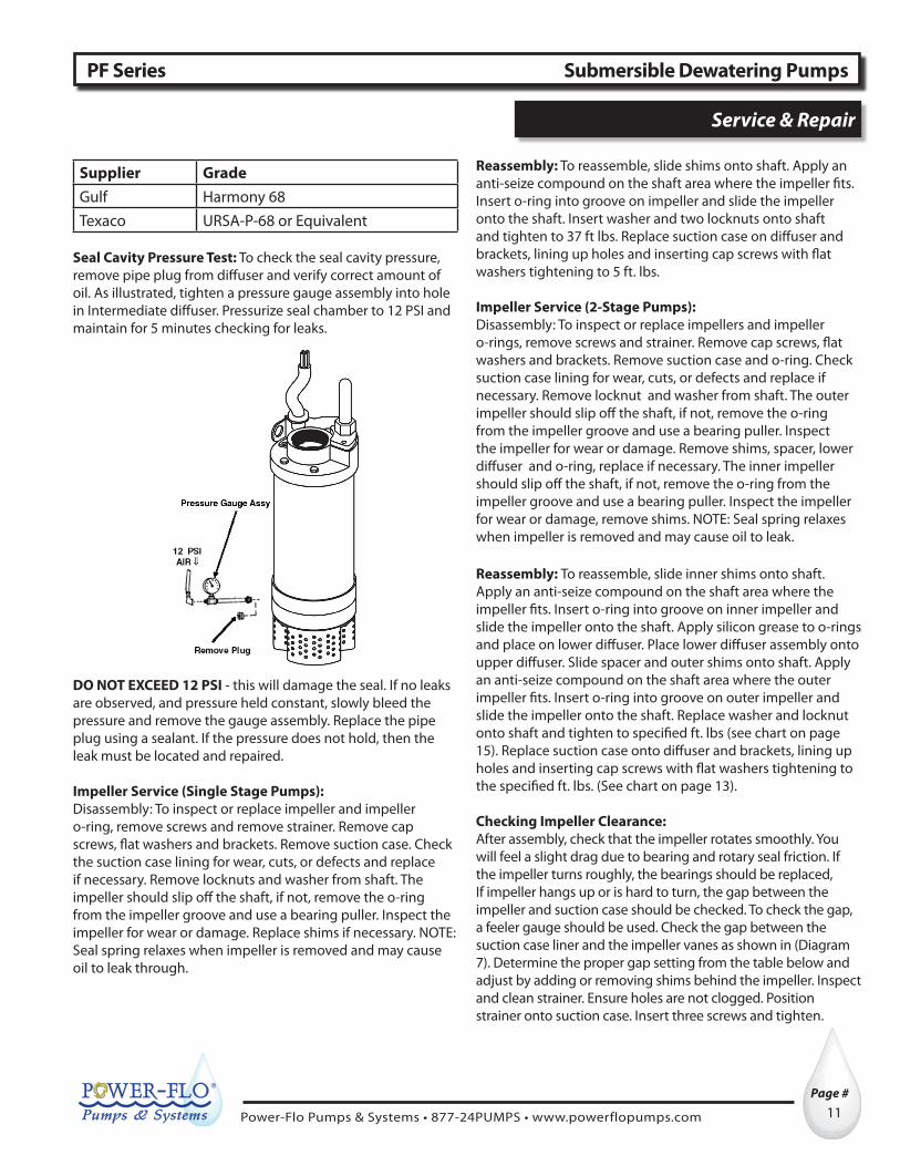
Repair Parts - 3/4HP & 1HP
PF01011, PF01311, PF01311SC Submersible Dewatering Pumps
For Repair Part Please supply: Model Number and MFG Date as shown on Name Plate, and Part Description and Part Number as shown on Parts List.
Capacitors For 01311 Self-Contained

Power-Flo Pumps & Systems • 877-24PUMPS • www.powerflopumps.com
Page # ®
18
Repair Parts - 3/4HP & 1HP For Repair Part Please supply: Model Number and MFG Date as shown on Name Plate, and Part Description and Part Number as shown on Parts List.
PF01011, PF01311, PF01311SC Submersible Dewatering Pumps
Item 3 Includes: 1, 2, 3A, 4 , 5, 6, 7, 8
Power-Flo Pumps & Systems • 877-24PUMPS • www.powerflopumps.com
®
19Page #
Parts List - 3/4HP & 1HP
PF01011, PF01311, PF01311SCV Submersible Dewatering Pumps
For Repair Part Please supply: Model Number and MFG Date as shown on Name Plate, and Part Description and Part Number as shown on Parts List.
NO. QTY. PART NO. DESCRIPTION1 1 V28003-2 Bushing, Strain Relief2 1 V112560 Bracket, Cable Support
3 1
V100723-14 Assembly, Cable & Gland 115v 25’ 14/4 SOOW
V100723-18 Assembly, Cable & Gland 230/460v 25’ 14/4 SOOW
V100723-14A Assembly, Cable & Gland, 25Ft, 115 w/plug 14/3 for, PF01311SCV
V100723-65 Assembly, Cable & Gland, 65Ft, 115 w/plug 14/3 for, PF01311SCV
3a 1
V100958-5 Cable 25 ft 3/4hp & 1hp 115v 14/4 SOOW
V100892-25 Cable 25 ft 3/4hp & 1hp 230v & 460v 14/4 SOOW
V100958-65 Cable 65 ft, 115v w/ plug 14/3, 1hp self contained model PF01311SCV
4 1 V21004-4 Washer, Cable Grip
5 1V12022-1 Bushing, 14/4V12022-3 Bushing, 14/3 (PF01311SCV)
6 1 V12061-1 Nut, Cable Grip7 1 V001900-2 Gland, Cable
8 1 V001902 Gasket, Terminal Box
9 1V100700-2 Discharge Head 3/4hp & 1hp
(Not for PF01311SCV model)
V100700-3 Discharge Head 1hp self contained model PF01311SCV
10 2 312000 Plug, Pipe 1/8 NPT11 1 303002 Screw, Rd. Hd. 10-32 x 1.25” Lg12 1 331004 Lockwasher #10
13 2 V31003-158 O-Ring, 129mm OD, 2.7mm CS
14 2 V31003-239 O-Ring, 100mm OD, 3.5mm CS
15 1 V30001 Spring, Bearing Load
16 2 V112543 Bearing 6203-2Z
17 1
V615017-001 * Outer Shell - 1 HP, PF01311A
V615017-002 Outer Shell - 3/4 HP & 1HP
V615017-003 Outer Shell - 1HP self contained model PF01311SCV
18 1
V615016-001 * Frame 1 hp, PF01311A
V615016-002 Frame 3/4 hp & 1hp
V615016-003 Frame 1hp self contained model PF01311SCV
19 1V088853 * Motor 1hp 115v/230v 1ph
(rotor “B” & stator “A”)
V088853-1SC Motor 1hp 115/230v 1ph, self contained model PF01311SCV
NO. QTY. PART NO. DESCRIPTION
19 1
V088854 * Motor 1hp 230/460v 3ph (rotor “B” & stator “A”)
V088856 Motor 3/4hp & 1hp, 115/230v 1ph (rotor & stator)
V088857 Motor 3/4hp & 1hp, 230/460v 3ph (rotor & stator)
20 1 V31036 Seal, shaft inboard, C/C/B
21 1 V31036C Seal, shaft outboard, S/S/B
22 1 V615171-2FK Diffuser 3/4 & 1hp23 1 V615172 Retainer, Seal
24 1V615170 Suction Case 3/4hp & 1hp
V615170A * Suction Case 1hp “A” & “SC”
25 13 330001 Washer, Flat, 1/4” SS26 8 300003 Screw, Cap, 1/4-20 x 3.25” Lg
27 1 V331005 Lockwasher, Impeller
28 1 V12015-2 Lock Nut, Impeller
29 1V100000-4 Strainer
V100000 Anti-Sludge Strainer, For PF01311SCV - OPTIONAL
30 2 V12014-1 Connector
31 1 V625-00163 Connector32 4 300002 Screw, Cap, 1/4-20 x 2” Lg33 1 V33241 Nameplate34 2 V28002-1 Rivet35 1 V2427493 Spiral Lubricator
36 1 V27002-50 Snap Rings37 1 V31003-026 O-ring, 35mm OD, 1.7mm CS38 2 303003 Screw, Rd. Hd, 6-31 x 1/2”
39 1 V21002-64 Shim .016”, 1 set of 31 V21002-65 Shim .032”, 1 set of 3
40 1 V353308-2 Key
41 1
V100200-2 Impeller 3/4hp - 3.58” OD, .48”V100200-3 Impeller 1hp - 3.58” OD, .55”
V100200-4 * Impeller 1hp “A” & “SCV”3.58” OD, .78”
42 2.6oz Purchase Locally #10, Non-Detergent Turbine, Seal Chamber Oil
43 2 V450001SC Capacitor, 25mfd 300v, 1hp for PF01311SCV
44 1 V64VP1001 2” CamLock Fitting for PF01311SCV
45 1 V62VP1001 2” Pipe Nipple for PF01311SCV
46 1 V90ROPE001 Rope, 30Ft, 1/4” Nylon for PF01311SCV
REPAIR KITS
V01000-OHK Overhaul Kit - 5, 8, 13, 14, 15, 16, 20, 21, 27, 28, 30, 31, 36, 37, 39, 40
IMPORTANT ! - 1Hp, Pump Models PF01311, PF01312, PF01332 & PF01334, Dated BEFORE December 2009 (Mfg Date on name plate “MC”), will use the parts indicated with (*). These items include #17, #18, #19, #24 & #41. These pumps Dated AFTER December 2009 (“AD”), will be labeled as Model Numbers PF01311A, PF01312A, PF01332A & PF01334A and will use the parts indicated with (*). Pump Models PF01311, PF01312, PF01332 & PF01334 Dated AFTER December 2009 (“AD”), will use the parts indicated with ().
Note: O-ring & snap ring sizes are Milimeters.

Power-Flo Pumps & Systems • 877-24PUMPS • www.powerflopumps.com
Page # ®
20
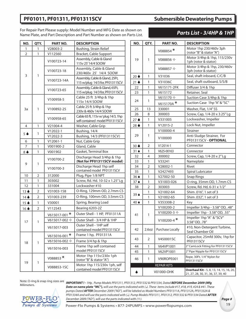
Repair Parts - 2, 2-1/2, 2-3/4, 3-1/2 & 5HPFor Repair Part Please supply: Model Number and MFG Date as shown on Name Plate, and Part Description and Part Number as shown on Parts List.
PF2000, PF25000, PF27000, PF35000, PF50000 Submersible Dewatering Pumps

Power-Flo Pumps & Systems • 877-24PUMPS • www.powerflopumps.com
®
21Page #
Repair Parts - 2, 2-1/2, 2-3/4, 3-1/2 & 5HPFor Repair Part Please supply: Model Number and MFG Date as shown on Name Plate, and Part Description and Part Number as shown on Parts List.
PF2000, PF25000, PF27000, PF35000, PF50000 Submersible Dewatering Pumps
Power-Flo Pumps & Systems • 877-24PUMPS • www.powerflopumps.com
Page # ®
22
Parts List - 2, 2-1/2, 2-3/4, 3-1/2 & 5HP For Repair Part Please supply: Model Number and MFG Date as shown on Name Plate, and Part Description and Part Number as shown on Parts List.
PF2000, PF25000, PF27000, PF35000, PF50000 Submersible Dewatering Pumps
NO. QTY. PART NO. DESCRIPTION1 11 330002 Washer, Flat2 5 301003 Screw, Hex Hd
3 1 V250700 Discharge Head 3” NPT w/ 2” NPT Adaptor V25009
4 2 V30001 Spring, Bearing Load5 1 V112543 Bearing 6203-2Z
61 V250555 Outer Shell
2hp, 2-1/2hp & 2-3/4hp 1 V500555 Outer Shell 3-1/2hp & 5hp 1 V511555 Outer Shell 5hp 230 1ph
71 V250500 Frame 2hp, 2-1/2hp & 2-3/4hp1 V500500 Frame 3-1/2hp & 5hp 1 V511500 Frame 5hp 230 1ph
8 1 V112544 Bearing 6205-2Z9 1 V27004-59 Snap Ring10 1 V501305 Wear Plate
11 1 V31003-035 O-Ring, 56mm ID, 1.8mm CS12 1 V500311 Retainer, Seal
13
1 V200200-6 Impeller 2hp 5.315”1 V250200-6 Impeller 2-1/2hp HH 5.315”
1 V275200-2 Impeller 2-1/2hp HV & 2-3/4hp 4.217”
1 V350200-7 Impeller 3-1/2hp 5.220”1 V500200-6 Impeller 5hp 5.315”
14 6 301000 Screw. Hex Hd15 2 V20002-38 Lock Nut, Impeller
16 1 V500000-1 Strainer
17
1 V250100-1 Suction Case 2hp, 2-1/2hp-HH
1 V500100-1 Suction Case 2-1/2hp-HV, 2-3/4hp & 5hp
1 V350100-1 Suction Case 3-1/2hp18 1 V500210 Lockwasher, Impeller19 1 V31003-117 O-Ring, 20.5mm ID, 2.6mm CS
20 1 V500407 Key, .093 x .13 x .688 Lg21 3 V500003 Bracket22 1 330003 Lockwasher23 3 302000 Screw, Pan Hd
24a 1 V21010-2 Shim .032”, 1 set of 4
24b 1 V21010-1 Shim .016”, 1 set of 425 4 303001 Screw, Rd. Hd
26 1 V500350 Seal, Outboard Shaft27 1 312001 Plug, Pipe NPT28 1 V500300-2 Diffuser
29 2 V31003-260 O-Ring, 175mm OD, 3.5mm CS
30 2 V31003-246 O-Ring, 113.9mm ID, 3.5mm CS
NO. QTY. PART NO. DESCRIPTION
31 4.6 oz Purchase Locally #10 Oil, Non-Detergent
Turbine, Seal Chamber
32
1 V250400 Rotor-2hp 115/230v 1Ph,2-1/2 & 2-3/4hp 230/460v 3Ph
1 V500400 Rotor-3-1/2hp 230v 1Ph5hp 230/460/575v 3Ph
1 V511400 Rotor 5hp 230v 1ph33 1 V27004-98 Retaining Ring
34
1 V250600 Stator-2-1/2hp, 230v/460v 3Ph1 V500600 Stator - 5hp 230/460v 3Ph1 V500635 Stator - 5hp 575v 3ph1 V200600 Stator 2hp 230v 1Ph1 V200600-15 Stator 2hp 115v 1Ph1 V200600-34 Stator 2-3/4hp 230v 1Ph1 V350612 Stator 3-1/2hp 230v 1Ph1 V511600 Stator 5hp 230v 1ph
35 1 V500750Stator Dam 2-1/2hp 230/460v 3Ph, 5hp 230/460/575v 3Ph
35 1 V500750-2Stator Dam 2hp 115v 1Ph, 2hp 230v 1Ph, 2-3/4hp & 3-1/2hp 230v 1Ph
36 1 303002 Screw, Rd. Hd37 1 331004 Lockwasher38 1 312000 Plug, Pipe NPT
39 2 V12026-1 Connector, 1 Phase6 V12026-2 Connector, 3 Phase
41 1 V2-31003-0025 Gasket
42 1 V31001 Seal, Inboard Shaft43 1 V500711-1 Gland, Cable
44 1 V12022-2 Bushing45 1 V12062 Nut, Cable Grip46 1 V350887-50 Cable - 50ft 12/4 SOOW47 1 V12020-2A Grip, Cable48 4 301001 Screw, Hex Hd.49 4 330001 Washer, Flat50 1 V33241 Nameplate51 4 V28002-3 Rivet52 1 V33012 Tag, Ground-Lead53 1 V2427494 Spiral Lubricator
54 1 V500710-2Assembly Cable & Gland 50ft, SOOW Includes Item #’s 43, 44, 45, 46, 47
V22527355-OHKOverhaul Kit - 4, 5, 8, 9, 11, 15, 18, 19, 20, 24a, 24b, 26, 29, 30, 35, 39, 41, 42, 44
Note: O-ring & snap ring sizes are Milimeters.

Power-Flo Pumps & Systems • 877-24PUMPS • www.powerflopumps.com
®
23Page #
Repair Parts - 5HP, 2 StageFor Repair Part Please supply: Model Number and MFG Date as shown on Name Plate, and Part Description and Part Number as shown on Parts List.
PF501322ST, PF501342ST Submersible Dewatering Pumps

Power-Flo Pumps & Systems • 877-24PUMPS • www.powerflopumps.com
Page # ®
24
For Repair Part Please supply: Model Number and MFG Date as shown on Name Plate, and Part Description and Part Number as shown on Parts List.Repair Parts - 5HP, 2 Stage
PF501322ST, PF501342ST Submersible Dewatering Pumps

Power-Flo Pumps & Systems • 877-24PUMPS • www.powerflopumps.com
®
25Page #
Repair Parts - 5HP, 2 StageFor Repair Part Please supply: Model Number and MFG Date as shown on Name Plate, and Part Description and Part Number as shown on Parts List.
PF501322ST, PF501342ST Submersible Dewatering Pumps
NO. QTY. PART NO. DESCRIPTION1 5 300009 Capscrew 5/16-18 x 2.5lg2 11 330005 Flat washer 5/163 1 V605012 Lockwasher4 5 V31009-011 Quad Ring
5 1 V250700 Discharge Head 3” NPT w/2” NPT Adaptor V25009
6 1 V30002-6 Bearing Loading Spring
7 1 V112543 Bearing 6203-2Z8 1 V500555 Outer Shell9 1 V550400 Rotor 5hp, 230v, 3ph9 1 V550400 Rotor 5hp, 460v, 3ph9 1 V550400 Rotor 5hp, 575v, 3ph
10 1 V500500 Frame11 1 V30009-4 Nilos Bearing Ring
12 1 V27006-244 Snap ring
13 1 112546 Bearing, Ball 6305-2Z
14 1 V31006 Shaft Seal, Inboard15 1 V550300-2 Upper Diffuser16 1 312001 Pipe Plug, 1/4”17 1 V501305 Wear Plate, Poly18 1 V815310 Seal Retainer
19 1 V31003-035 O-ring, 56 ID, 1.8 CS
20 2 V550200-2 Impeller, Stainless Upper and Lower 5.315”
21 2 V500407 Key, .093 x .13 x .688 lg
22 2 V31003-117 O-Ring, 20.5 ID, 2.6 CS23 3 302000 Pan Hd Screw24 3 V500003 Bracket25 1 V500000-1 Strainer26 1 V550100 Suction Case
27 1 V20002-43 Lock Nut, Impeller
28 1 V550211 Lockwasher, Impeller
29 2 V815210-1 Shim, 0.16”, 1 set of 10
30 2 V815210-2 Shim, .032”, 1 set of 1031 6 300010 Capscrew, 5/16-18 x6.532 1 V550209 Spacer
33 2 V31003-166 O-Ring, 171.12 ID, 2.6 CS34 1 V500600 Stator 5hp, 230v, 3ph34 1 V500600 Stator 5hp, 460v, 3ph34 1 V500635 Stator 5hp, 575v, 3ph
NO. QTY. PART NO. DESCRIPTION
35 1 V550303Lower Diffuser Assy Includes, Alum. Ring & Plastic Liner
36 4 303001 Rh. Hd Screw37 1 V815350 Shaft Seal, Outboard, S/S/B
38 1 V27002-87 Retaining Ring39 2 V31003-260 O-ring, 175 OD, 3.5 CS
40 2 V31003-246 O-ring, 113.9 ID, 3.5 CS41 1 V27004-98 Snap ring
42 1V500750 Stator dam 230/460 vV500750-1 Stator dam 575v
43 1 300002 Rd hd Screw44 1 312000 Pipe Plug
45 2 V12026-1 Connector, 1 Phase
6 V12026-2 Connector, 3 Phase
46 A/R Purchase Locally Epoxy
47 1 V2-31003-0025 Gasket48 1 V500711-1 Gland, cable
49 1 V12022-2 Bushing50 1 V12062 Cable Grip Nut51 1 V12020-2A Cable Grip52 1 V350887-50 Cable 50 ft 12/4 SOOW53 2 300008 Capscrew54 3 330001 Lockwasher55 4 V28002-1 Rivet56 1 V33241 Nameplate57 1 331004 Lockwasher
58 1 V500710-2Cable & Gland Assy Includes Item #’s 48, 49, 50, 51, 52
4.6 oz Purchase Locally #10 Oil, Non-Detergent Turbine, Seal Chamber
REPAIR KIT
V500002ST-OHK
Overhaul Kit - 6, 7, 12, 13, 14, 19, 21, 22, 27, 28, 29, 30, 33, 37, 39, 40, 42, 45, 47, 49
(*) - Item 58 includes: 48, 49, 50, 51, 52.Note: O-ring & snap ring sizes are Milimeters.

Power-Flo Pumps & Systems • 877-24PUMPS • www.powerflopumps.com
Page # ®
26
For Repair Part Please supply: Model Number and MFG Date as shown on Name Plate, and Part Description and Part Number as shown on Parts List.Repair Parts - 6HP, 10HP, 15HP
PF60112, PF81000, PF81500 Series Submersible Dewatering Pumps

Power-Flo Pumps & Systems • 877-24PUMPS • www.powerflopumps.com
®
27Page #
For Repair Part Please supply: Model Number and MFG Date as shown on Name Plate, and Part Description and Part Number as shown on Parts List. Repair Parts - 6HP, 10HP, 15HP
PF60112, PF81000, PF81500 Series Submersible Dewatering Pumps

Power-Flo Pumps & Systems • 877-24PUMPS • www.powerflopumps.com
Page # ®
28
For Repair Part Please supply: Model Number and MFG Date as shown on Name Plate, and Part Description and Part Number as shown on Parts List.Repair Parts - 6HP, 10HP, 15HP
PF60112, PF81000, PF81500 Series Submersible Dewatering Pumps
NO. QTY. PART NO. DESCRIPTION1 2 301004 Screw, Hex hd2 2 331002 Lock Washer3 2 310000 Nut, Hex4* 21 330004 Washer, Flat5 7 300005 Screw, Cap6 4 301007 Screw, Hex Hd7 1 V815720 Adapter, Discharge8 1 V31003-244 O-Ring, 115 OD, 3.5 CS9 1 V615700 Discharge Head
10 2 V31003-366 O-Ring, 197 OD, 5.3 CS11 2 V31003-448 O-Ring, 254 OD, 7 CS12 2 V30002-3 Spring, Bearing Load
131 V810555 Shell, Outer- 6 & 10hp1 V815555 Shell, Outer- 15hp
14 1 V34007 Bearing 6304-2Z
151 V610500-1 Frame - 6 & 10hp1 V615500-2 Frame - 15hp
16A 1 V610400 Rotor - 6 & 10hp , 460v/230v16A 1 V615400 Rotor - 15hp , 230v/460v16B 1 V600600 Stator - 6hp 230v, 1Ph16B 1 V810630 Stator - 10hp 460v/230v16B 1 V815630 Stator - 15hp 230v/460v17 1 312002 Plug, pipe 1/2” NPT18 1 V31003-273 O-Ring, 251.8 OD, 3.6 CS19 1 V815300 Diffuser
201 V810105 Suction Case 10hp-HH1 V815100 Suction Case 10hp & 15hp HV1 V815105 Suction Case 6 & 15hp-HH
21
1 V600200-6 Impeller 6hp, 7.154”1 V810203-3 Impeller 10hp-HH 7.795”1 V810200-2 Impeller 10hp-HV 7.154”1 V815203-2 Impeller 15hp-HH 7.795”1 V815200-2 Impeller 15hp-HV 7.146”
22 4 V815010 Bolt, Strainer23 4 301002 Screw, Hex hd24 4 330005 Washer, Flat25 1 V815000-1 Strainer26 1 V31003-122 O-Ring, 34 OD, 3.1 CS27 1 V815211 Lockwasher, impeller28 1 V20002-38 Lock Nut, impeller29 1 V815410 Key, .124 sq x .878 lg
30A 1 V815210-1 Shim .016”, 1 set of 1030B 1 V815210-2 Shim .032”, 1 set of 10
314 300006 Screw, Cap HH4 300007 Screw, Cap HV & 6hp
NO. QTY. PART NO. DESCRIPTION32 1 V815350 Shaft Seal, Outboard33 4 303001 Screw, Rd. Hd -4 per bag34 1 V815310 Retainer, Seal35 1 V31003-035 O-Ring, 56 ID, 1.8 CS36 1 V27002-87 Snap Ring, 20.5 ID, 1 Thk37 1 V31006 Shaft Seal, Inboard38 1 V34004 Bearing, 630739 4 301005 Screw, Hex Hd. Cap40 4 331000 Lock Washer41 1 V815311 Retainer, Bearing42 1 V840752 Stator Dam43 1 V31003-015 O-Ring, 13.2 ID, 1.9 CS44 1 V615758 Plug Assembly46 1 303000 Screw, Rd. Hd.47 1 331003 Lockwasher
483 V12029 Connector, 1 Phase4 V12029-1 Connector, 230V, 3 Ph6 V12029-2 Connector, 460V, 3 Ph
49* 2 V31003-138 O-Ring, 53.6 ID, 2.6 CS50* 1 V840760-4 Clamp, Cable51* 2 330005 Washer, Flat52* 2 301009 Screw, Hex Hd.53* 1 V840711 Gland, Cable54* 2 300004 Screw, Cap
55
1 V600710 Assembly, cable & gland, 6HP, 230V, 1Ph, 6/4
1 V840710-44 Assembly, cable & gland, 10 & 15HP, 230V, 6/4
1 V840710-5 Assembly, cable & gland, 10 & 15HP, 460V, 12/4
56*1 V840759-1 Grip, Cable Washer 230v1 V840759-2 Grip, Cable Washer 460v
57*1 V840751-3 Bushing 230v1 V840751-6 Bushing 460v
58* 1 V840755 Nut, Cable Grip
62*1 V600112-50 Cable -50ft 230/1, 6/4 SOOW1 V810893-50 Cable - 50ft 230v 6/4 SOOW1 V350887-50 Cable - 50ft 460v 12/4 SOOW
25.0 oz Purchase Locally #10 Oil, Non-Detergent
Turbine, Seal ChamberREPAIR KITS
V60112-OHK Overhaul Kit - 8, 10, 11, 12, 14, 18, 26, 27, 28, 29, 30A, 30B, 32, 35, 36, 37, 38, 42, 43, 48, 49, 57
V81000-OHK
(*) - Item 55 includes: 4 (Qty 2)`, 49, 50, 51, 52, 53, 54, 56, 57, 58, 62.Note: O-ring & snap ring sizes are Milimeters.

Power-Flo Pumps & Systems • 877-24PUMPS • www.powerflopumps.com
®
29Page #
For Repair Part Please supply: Model Number and MFG Date as shown on Name Plate, and Part Description and Part Number as shown on Parts List. Repair Parts - 25HP & 50HP
PF82500, PF85000 Series Submersible Dewatering Pumps

Power-Flo Pumps & Systems • 877-24PUMPS • www.powerflopumps.com
Page # ®
30
For Repair Part Please supply: Model Number and MFG Date as shown on Name Plate, and Part Description and Part Number as shown on Parts List.Repair Parts - 25HP & 50HP
PF82500, PF85000 Series Submersible Dewatering Pumps

Power-Flo Pumps & Systems • 877-24PUMPS • www.powerflopumps.com
®
31Page #
For Repair Part Please supply: Model Number and MFG Date as shown on Name Plate, and Part Description and Part Number as shown on Parts List. Parts List - 25HP & 50HP
PF82500, PF85000 Series Submersible Dewatering Pumps
NO. QTY. PART NO. DESCRIPTION1 1 V840732 Adapter, Discharge2 6 301007 Screw, Hex Hd.
3 † 1 V31003-260 O-Ring, 163 ID, 3.5 CS4 1 V840700 Discharge Head5 9 300000 Screw, Cap
6 † 2 V6458 O-Ring, 293.5 ID, 7 CS7 1 V840555-1 Shell, Outer 25hp7 1 V850555 Shell, Outer 50hp
81 V840500 Frame 25hp1 V850500 Frame 50hp
9 1 V840313 Retainer, Bearing10 4 301006 Screw, Hex Hd. Cap11 4 331001 Lockwasher
12 † 2 V31003-446 O-Ring, 218 ID, 7 CS13 1 V840300 Diffuser
14 † 1 V31003-038 O-Ring, 66.6 ID, 1.8 CS15 4 303001 Screw, Rd. Hd
16 † 1 V31003-277 O-Ring, 292.2 ID, 3 CS17A 1 set 10 V840210-2 Shim .010” x .79” ID, 25hp17B 1 set 10 V840210-3 Shim .020” x .79” ID, 25hp17A † 1 set 4 V21003-43 Shim .020” x 1.043 ID, 50hp17B † 1 set 4 V21003-44 Shim .010” x 1.043” ID, 50hp
184 300001 Screw, Cap HH4 300007 Screw, Hd HV
191 V840410 Key .15” sq x .80” lg, 25hp1 † V850410 Key .25” sq x 1” lg. 50hp
201 V840211 Lockwasher, Impeller 25hp1 † V21016 Lockwasher, Impeller 50hp
212 V20002-43 Lock Nut, Impeller 25hp
1 V850209 Lock Nut, Impeller 50hp22 1 V825000-1 Strainer23 5 301002 Screw, Hex Hd24 5 330005 Washer, Flat25 5 V825010 Bolt, Strainer26 25 330003 Washer, Flat
27 1 V31003-122 O-Ring, 34 OD, 3.1 CS, 25hp (for 25hp impeller only)
281 V840100-4 Suction Case
25hp & 50hp - HH1 V840100 Suction Case 25hp - HV1 V840100-8 Suction Case 50hp - HV
29 † 1 V840350 Seal, Outboard 25HP & 50HP30 1 V825203-1 Impeller 25hp HH 8.65”30 1 V825200-2 Impeller 25hp HV 8.02”30 1 V850203-2 Impeller 50hp HH 8.46”30 1 V850200-2 Impeller 50hp HV 8.02”
NO. QTY. PART NO. DESCRIPTION31 1 V840310 Retainer, Seal32 1 312002 Plug, Pipe NPT
33 † 1 V27002-125 Snap Ring, 29.6 ID, 1.2 Thk
34 32oz Purchase Locally
#10 Oil Non-Detergent Turbine, Seal Chamber
35 † 1 V31020 Shaft Seal, Inboard36 † 1 V34016 Bearing, Angular 5310A-2Z37 † 1 V27002-200 Snap Ring, 45.8 id, 2 CS
38 1 V825630 Stator 25hp, 230v38 1 V850634 Stator 50hp, 460v39 1 V825408 Rotor 25hp, 230v, 460v, 575v39 1 V850400 Rotor 50hp, 460v
40 † 1 V34013 Bearing 6306-2Z
411 V840750 Stator Dam 25 Hp1 † V840750-1 Stator Dam 50 hp
42 † 1 V30002-5 Spring, Bearing Load43 † 1 V840758 Plug Assembly
44 † 1 V31003-015 O-Ring, 13.2 ID, 1.9 CS(for air plug 25hp & 50hp)
46 1 303000 Screw, Rd Hd47 1 331003 Lockwasher
48 †4 V12026-1 Connector, 230V, 3 Ph6 V12026-2 Connector, 460V, 3 Ph
49* † 2 V31003-138 O-Ring, 53.6 ID, 2.6 CS50* 1 V840715 Gland, Cable51* 2 301008 Screw, Hec Hd.52* 2 330005 Washer, Flat53* 1 V825907-50 Cable - 50ft 4/4 SOOW54 1 Contact Factory Nameplate55* 2 300004 Screw, Cap56* 2 330004 Washer, Flat
57* † 1 V840749-2 Bushing58* 1 V840759-2 Grip, Cable Washer59* 1 V840748 Cable Grip Nut60 1 V850208-1 Bushing, taper lock 50hp61* 1 V840760-4 Clamp, Cable62 4 Contact Factory Rivets63 1 V840710-10 Assembly, Cable & Gland *
REPAIR KITS
V82500-OHKOverhaul Kit - 3, 6, 12, 14, 16, 17a, 17b, 19, 20, 21, 27, 29, 33, 35, 36, 37, 40, 41, 42, 43, 44, 48, 49, 57† V85000-OHK
(*) - Item 63 includes: 49, 50, 51, 52, 53, 55, 56, 57, 58, 59, 61.Note: O-ring & snap ring sizes are Milimeters.

Power-Flo Pumps & Systems • 877-24PUMPS • www.powerflopumps.com
Page # ®
32
PART NO. DESCRIPTION SIZE MATERIAL300000 Screw, Cap 1/2-13 x 3.75” lg Stainless Steel300001 Screw, Cap 1/2-13 x 5.00” lg Stainless Steel300002 Screw, Cap 1/4-20 x 2.00” lg Stainless Steel300003 Screw, Cap 1/4-20 x 3.25” lg Stainless Steel300004 Screw, Cap 3/8-16 x 1.00” lg Stainless Steel300005 Screw, Cap 3/8-16 x 3.25” lg Stainless Steel300006 Screw, Cap 3/8-16 x 5.00 lg Stainless Steel300007 Screw, Cap 3/8-16 x 5.50 lg Stainless Steel300008 Screw, Cap 1/4-20 x .875” lg Stainless Steel300009 Screw, Cap 5/16-18 x 2.50” lg Stainless Steel300010 Screw, Cap 5/16-18 x 6.50” lg Stainless Steel301000 Screw, Hex Hd. 5/16-18 x 3.50” lg Stainless Steel301001 Screw, Hex Hd. .25-20 x .875” lg Stainless Steel301002 Screw, Hex Hd. 5/16-18 x .50 lg Stainless Steel301003 Screw, Hex Hd. 5/16-18 x 2.25” lg Stainless Steel301004 Screw, Hex Hd. Cap 1/2-13 x 5.50” lg Stainless Steel301005 Screw, Hex Hd. Cap 10-24 x .625” lg Zinc Plated301006 Screw, Hex Hd. Cap 10-24 x .625” lg Stainless Steel301007 Screw, Hex Hd. Cap 3/8-16 x 1.125” lg Stainless Steel301008 Screw, Hex Hd. Cap 5/16-18 x 1.25 lg Stainless Steel301009 Screw, Hex Hd. Cap 5/16-18 x 1.50 lg Stainless Steel302000 Screw, Pan Hd. 1/2-20 x .50” lg Stainless Steel303000 Screw, Rd. Hd. 1/4-20 x .375” lg Bronze303001 Screw, Rd. Hd. 10-24 x .50” lg Stainless Steel303002 Screw, Rd. Hd. 10-32 x .25” lg Bronze303003 Screw, Rd. Hd. 6-31 x .50” lg Stainless Steel310000 Nut, Hex 1/2”-13 Stainless Steel312000 Plug, Pipe NPT .125 Stainless Steel312001 Plug, Pipe NPT .25 Stainless Steel312002 Plug, Pipe NPT 1/2” Stainless Steel330001 Washer, Flat .25 Stainless Steel330002 Washer, Flat .32 Stainless Steel330003 Washer, Flat 1/2” Stainless Steel330004 Washer, Flat 3/8” Stainless Steel330005 Washer, Flat 5/16” Stainless Steel330006 Washer, Flat .25 Zinc Plated331000 Lockwasher #10 Cad Plated331001 Lockwasher #10 Stainless Steel331002 Lockwasher 1/2” Stainless Steel331003 Lockwasher 1/4” Cad Plated331004 Lockwasher 10 Steel331005 Lockwasher, Impeller 3/8” Stainless Steel
PF Series Submersible Dewatering Pumps
Hardware Parts List

Power-Flo Pumps & Systems • 877-24PUMPS • www.powerflopumps.com
®
33Page #
Diagram 20
2.75, 3.5, 5 & 6HP Single Phase (ONLY)
Control Box Schematics
PF Series Submersible Dewatering Pumps

Power-Flo Pumps & Systems • 877-24PUMPS • www.powerflopumps.com
Page # ®
34
0.75 - 1HP 1Phase Control
2HP 1Phase Control
Item No.
Name Description Part No.
1 Enclosure7.59W x 8.66H x 4.80D NEMA 3R V4500500ENC
2 Cable w/ Plug 14/4 V4500404CA3 Connection Diagram See Page 33 ----
4Fuse, 115v/0.75hp 12A V4500200FFuse, 115v/1hp 15A V4500201FFuse, 230v/0.75-1hp 8A V4500202F
5 Run Capacitor 370V, 35MFD V4500002C6 Start Capacitor 250V, 64MFD V4500003C7 Ground Lug V4500400LUG
8Relay, 115v TI 4CR-1-758 V4500100RRelay, 230v TI 4CR-1-705 V4500101R
9 Fuse Clamp V4500401CLP
Control Box, 3/4 & 1HP, 115V P/N: V101811Control Box, 3/4 & 1HP, 230V P/N: V101812
Item No.
Name Description Part No.
1 Enclosure8.08W x 10.12H x 4.47D NEMA 3R V4500501ENC
2 Connection Diagram See Page 33 ----
3
Circuit Breaker115v 240V, 32A V4500300B
Circuit Breaker 230v 240V, 15A V4500301B
4
Start Capacitor 115v 800MFD/125V V4500004C
Start Capacitor 230v 200MFD/250V V4500005C
5Relay 115v HY-D2-165/40-11CU V4500102RRelay 230v MARS 169 #19169 V4500103R
6 Ground Lug V4500400LUG7 Connector V4500402CON
Control Box, 2HP, 115V P/N: V200811Control Box, 2HP, 230V P/N: V200812
PF Series Submersible Dewatering Pumps
Control Box Components
Power-Flo Pumps & Systems • 877-24PUMPS • www.powerflopumps.com
®
35Page #
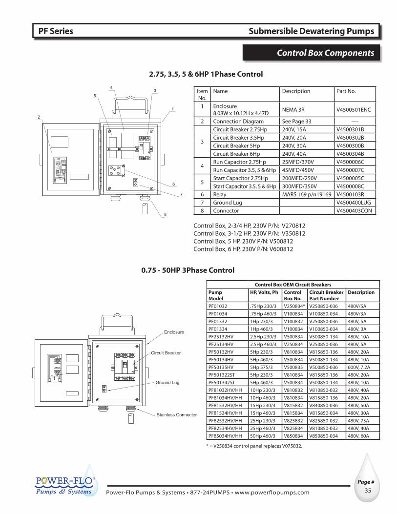
Control Box OEM Circuit BreakersPump Model
HP, Volts, Ph Control Box No.
Circuit Breaker Part Number
Description
PF01032 .75Hp 230/3 V250834* V250850-036 480V/5APF01034 .75Hp 460/3 V100834 V100850-034 480V/3APF01332 1Hp 230/3 V100832 V250850-036 480V, 5APF01334 1Hp 460/3 V100834 V100850-034 480V, 3APF25132HV 2.5Hp 230/3 V500834 V500850-134 480V, 10APF25134HV 2.5Hp 460/3 V250834 V250850-036 480V, 5APF50132HV 5Hp 230/3 V810834 V815850-136 480V, 20APF50134HV 5Hp 460/3 V500834 V500850-134 480V, 10APF50135HV 5Hp 575/3 V500835 V500850-036 600V, 7.2APF501322ST 5Hp 230/3 V810834 V815850-136 480V, 20APF501342ST 5Hp 460/3 V500834 V500850-134 480V, 10APF81032HV/HH 10Hp 230/3 V810832 V810850-032 480V, 40APF81034HV/HH 10Hp 460/3 V810834 V815850-136 480V, 20APF81532HV/HH 15Hp 230/3 V815832 V840850-036 480V, 50APF81534HV/HH 15Hp 460/3 V815834 V815850-034 480V, 30APF82532HV/HH 25Hp 230/3 V825832 V825850-032 480V, 75APF82534HV/HH 25Hp 460/3 V825834 V810850-032 480V, 40APF85034HV/HH 50Hp 460/3 V850834 V850850-034 480V, 60A
* = V250834 control panel replaces V075832.
0.75 - 50HP 3Phase Control
2.75, 3.5, 5 & 6HP 1Phase Control
Item No.
Name Description Part No.
1 Enclosure8.08W x 10.12H x 4.47D NEMA 3R V4500501ENC
2 Connection Diagram See Page 33 ----
3
Circuit Breaker 2.75Hp 240V, 15A V4500301BCircuit Breaker 3.5Hp 240V, 20A V4500302BCircuit Breaker 5Hp 240V, 30A V4500300BCircuit Breaker 6Hp 240V, 40A V4500304B
4Run Capacitor 2.75Hp 25MFD/370V V4500006CRun Capacitor 3.5, 5 & 6Hp 45MFD/450V V4500007C
5Start Capacitor 2.75Hp 200MFD/250V V4500005CStart Capacitor 3.5, 5 & 6Hp 300MFD/350V V4500008C
6 Relay MARS 169 p/n19169 V4500103R7 Ground Lug V4500400LUG8 Connector V4500403CON
Control Box, 2-3/4 HP, 230V P/N: V270812Control Box, 3-1/2 HP, 230V P/N: V350812Control Box, 5 HP, 230V P/N: V500812Control Box, 6 HP, 230V P/N: V600812
PF Series Submersible Dewatering Pumps
Control Box Components

Power-Flo Pumps & Systems • 877-24PUMPS • www.powerflopumps.com
Page # ®
36
PF Series Submersible Dewatering Pumps
LIMITED WARRANTY
Manufacturer warrants, to the immediate purchaser and subsequent initial owner during the warranty period, every new pump to be free from defects in material and workmanship under normal use and service, when properly used and maintained, for a period of eighteen (18) months from date of manufacture or twelve (12) months from date of installation (which ever comes first). Failure due to wear due to excessive abrasives is not covered. The initial owner is the purchaser who first uses the pump after its initial installation, or for non-permanent installation, the first owner who uses the pump. The date of installation shall be determined by a dated sales receipt noting the model and serial number of the pump. The dated sales receipt must accompany the returned pump. Product will be repaired, replaced or remanufactured at Manufacturer’s option. No allowance will be made for shipping charges, damages, labor or other charges that may occur due to product failure, repair or replacement. This warranty does not apply to and there shall be no warranty for any material or product that has been disassembled without prior approval of Manufacturer, subjected to misuse, misapplication, neglect, alteration, accident or act of God; that has not been installed, operated or maintained in accordance with Manufacturer’s installation instructions; that has been exposed to outside substances including but not limited to the following: sand, gravel, cement, mud, tar, hydrocarbons, hydrocarbon derivatives (oil, gasoline, solvents, etc.), or other abrasive or corrosive substances, wash towels or feminine sanitary products, etc. in all pumping applications. The warranty set out in the paragraph above is in lieu of all other warranties expressed or implied; and we do not authorize any representative or other person to assume for us any other liability in connection with our products. Contact Manufacturer at: 1-877-24PUMPS or www.powerflopumps.com, Attention: Customer Service Department, to obtain any needed repair or replacement of part(s) or additional information pertaining to our warranty.
MANUFACTURER EXPRESSLY DISCLAIMS LIABILITY FOR SPECIAL, CONSEQUENTIAL OR INCIDENTALDAMAGES OR BREACH OF EXPRESSED OR IMPLIED WARRANTY; AND ANY IMPLIED WARRANTY OF FITNESS FOR A PARTICULAR PURPOSE AND OF MERCHANTABILITY SHALL BE LIMITED TO THE DURATION OF THE EXPRESSED WARRANTY.
Some states do not allow limitations on the duration of an implied warranty, so the above limitation may not apply to you. Some states do not allow the exclusion or limitation of incidental or consequential damages, so the above limitation or exclusion may not apply to you. This warranty gives you specific legal rights and you may also have other rights which vary from state to state.