Embed Size (px)
Citation preview

Proudly Designed and Manufactured in New Zealand
Installation & Programming Guide
Alert Version
Arrowhead Alarm Products Ltd
8 Zone Control
PDF created with FinePrint pdfFactory trial version http://www.pdffactory.com

630 Great South Road Greenlane
AUCKLAND
PO Box 14 547 AUCKLAND 6
NEW ZEALAND
Designed & Manufactured in New Zealand to Meet NZS:4301/93
Copyright by Arrowhead Alarm Products Ltd July 2000 Alert V8.1 and above.
To the best of our knowledge the information contained in this manual is correct at the time of printing. Arrowhead Alarm Products Ltd reserve the right to make changes to
the features and specifications at any time without notice in the course of product development.
PHONE: (09) 579 7506 FAX: (09) 579 0891 FREEPHONE: 0800 700 123
Arrowhead Alarm Products Ltd
PDF created with FinePrint pdfFactory trial version http://www.pdffactory.com

Page 3
INTRODUCTION............................................................................................... 4 PACKAGE CONTENTS .................................................................................... 4 CONNECTION DIAGRAM................................................................................. 5 INPUTS ............................................................................................................. 6 OUTPUTS ......................................................................................................... 7 ALERT KEYPADS............................................................................................. 8 MEMORY VIEWING MODE.............................................................................. 9 KEYPAD INSTALLATION ............................................................................... 10 KEYPAD ADDRESS ASSIGNMENT............................................................... 10 KEYPAD FUNCTIONS.................................................................................... 11 INSTALLING RX-16 RADIO RECEIVER ........................................................ 11 ACCESSING & EXITING PROGRAM MODES .............................................. 12 USER CODE PROGRAMMING...................................................................... 13 USER CODE OPTIONS.................................................................. ............... 14 OUTPUT OPTION PROGRAMMING.............................................................. 14 ZONE ALARMS TO OUTPUTS ...................................................................... 15 MONITOR ALARMS TO OUTPUTS ............................................................... 16 24 HOUR ALARMS TO OUTPUTS................................................................. 16 DAY ZONES TO OUTPUTS ........................................................................... 16 RADIO PENDANTS TO OUTPUTS ................................................................ 16 AREA “A” OPTIONS ....................................................................................... 17 AREA “A” OUTPUT OPTIONS........................................................................ 17 AREA “B” OPTIONS........................................................................................ 18 AREA “B” OUTPUT OPTIONS........................................................................ 19 ZONE DOUBLING........................................................................................... 20 ZONE PROGRAM OPTIONS.......................................................................... 20 ENTRY DELAY TIMES.................................................................................... 21 EXIT DELAY TIMES...........................................................…......................... 21 TWO TRIGGER TIMER.........................................................…...................... 21 DAY MODE TIMER TO KEYPAD BUZZER.................................................... 22 OUTPUT TIMING OPTIONS........................................................................... 22 LOADING RADIO ZONES............................................................................... 23 RADIO ZONE OPTIONS................................................................................. 23 LOADING RADIO PENDANTS ....................................................................... 24 RADIO PENDANT OPTIONS “A”.................................................................... 24 RADIO PENDANT OPTIONS “B”.................................................................... 25 KEYPAD PARTITION ASSIGNMENT........................................................…. 26 KEYPAD PANIC BUTTON ENABLE............................................................... 26 MISCELLANEOUS PANEL OPTIONS............................................................ 26 DURESS DIGIT ............................................................................................... 27 RESET DEFAULTS......................................................................................... 27 CLEAR MEMORY EVENT BUFFER............................................................... 27 WALK-TEST MODE ENABLE......................................................................... 27 PROGRAM SUMMARY................................................................................... 28
CONTENTS
PDF created with FinePrint pdfFactory trial version http://www.pdffactory.com

Page 4
INTRODUCTION This Arrowhead Alert Version V8 alarm control panel has been designed to provide the most requested features for both the installer & the end-user. These features include ease of installation, ease of programming and user friendly operation all in a package which is reliable, functional and attractive. Utilising many years of experience in the security industry and implementing valuable feedback, we are proud to provide you with a new generation of alarm controller. The Alert V8 is a New Zealand designed and built product which brings you the quality and features which you deserve at an affordable price. In addition to the the advanced design, only the highest quality components have been used in the production of this Alert panel to ensure the highest degree of reliability. This manual will guide you through the installation and programming of your Alert alarm panel. For additional information regarding the operation instructions and options, please refer to the enclosed “Alert User’s Guide”.
PACKAGE CONTENTS
This Arrowhead Alert package should contain the following items; 1 x Alert controller PCB 1 x Alert new generation backlit keypad 1 x Alert keypad zone list 1 x Alert Users Guide 1 x Alert cabinet & lid 1 x 17 volt 1.4a Telepermitted mains transformer 1 x Cabinet hardware accessory pack including, 1 x Alert installation & programming guide 1 x Spare 1.5a fuse 1 x Cabinet tamper switch 1 x Cabinet tamper bracket 1 x Tamper switch wire set 2 x Cabinet lid screws 8 x 2k2 (red, red, red) end of line resistors 6 x 4k7 (yellow, purple, red) end of line resistors 6 x 8k2 (grey, red, red) end of line resistors If any of these items are missing from this package, please contact the Arrowhead branch where you placed your order.
PDF created with FinePrint pdfFactory trial version http://www.pdffactory.com

Page 5
+ _
0V
17V
Dat
Clk
Neg
Pos
0V
12V
1&5
0V
2&6
3&7
4&8
0V
Tmp
0V
12V 1 2 3
AC
AC
Heatsink
F1
1.5A
F2 3A
Alert V8.0
230V AC Input
RED
BLK
+ _
Battery
Mains Earth
Alert Keypad Pos
Neg
Gnd Ant
Clock
Data
RX-16/303 Receiver
0v 12v
2k2
Non-Latching Smoke Detector with Normally Open Contacts
+ _
Passive Infra- Red Detector
0v
12v
Tmp
Tmp
Com
N/C
2k2
2k2
2k2
Ext Alarm-MET-SP
Internal Alarm-Piezo
+ _
2k2
CONNECTION DIAGRAM
PDF created with FinePrint pdfFactory trial version http://www.pdffactory.com

Page 6
2k2
Tamper Alarm Contact
n/c or n/o
4k7
Alarm Contact n/c or n/o
8k2 Tamper
2k2
Tamper Alarm Contact
n/c or n/o
4k7
INPUTS The Alert V8 has 5 separate programmable monitored analogue inputs, 4 x Programmable, multi-state detection inputs 1 x Programmable tamper circuit
Each input must be terminated with the appropriate value or combination of end-of-line resistors, even if the input is unused.
ZONE INPUTS - Each of the 4 zone inputs can be assigned one of the following configuration options; Type 1(4Z) Single-End-of-Line (EOL) zone with no tamper (4 zones). Type 2(8Z) Double-End-of-Line (EOL) zones with open/short circuit tamper per input (8 zones) . The following table shows end-of-line resistor configurations.
Zone Type
Low Zone Resistor
Hi Zone Resistor
Tamper End-of-line
4Z (No Tampers) 2k2 - -
8Z (with 8 Tampers) 4k7 8k2 2k2
Type 4Z - 4 Zones, no tamper Type 8Z - 4 Zones with tamper
Type 8Z - 8 Zones with tampers
Option 1
NOTE: The Single EOL option requires only one 2K2
resistor per input. The Dual EOL option
needs one 2K2 per input to seal the zone tamper and a 4K7 plus an 8K2 for the two zones (Low & High). The default setting for Dual EOL is the alarm contact shorts out the Resistor
(4K7 or 8K2).
n/c
n/o 2k2
PDF created with FinePrint pdfFactory trial version http://www.pdffactory.com

Page 7
INPUTS cont. TAMPER - A 24Hr tamper circuit is available for monitoring tamper status of detectors, junction boxes, cabinets and satellite sirens etc. This Tamper circuit is programmable with 2 options (P170E1E) either normally closed loop or 2k2 EOL supervision (the default is normally closed loop). The tamper circuit must be terminated with an end-of-line resistor if 2k2 EOL supervision is selected. The activation events and outputs for this tamper circuit are mapped in the same manner as for detection zones 1-8. In addition to the Analogue monitoring inputs, you will find the following system inputs on your Alert V8 control PCB; AC - Connect the two low voltage wires (no polarity) from the transformer to the terminals marked AC on the Alert PCB. The Alert includes a mains transformer rated at 1.4 amps at 17 volts. EARTH - Always connect the mains earth to the appropriate terminal on the mains terminal block in the control box cabinet. Also connect a lead from this earth point to the terminal marked with the Earth symbol (next to the AC terminals) on the Alert PCB. BATTERY - Connect a sealed lead acid rechargeable 12V d.c. battery to these red and black battery leads. Be careful to observe correct polarity as damage may occur from incorrect connection. The minimum recommended battery capacity is 7 amp hours. Battery charge current at these terminals is limited to 350mA maximum. The battery connection is fuse protected by fuse F2 ( 3A). To test the battery, disconnect the AC supply for about 60 seconds. The system Led will flash after about 5-10 seconds of removing the AC supply. The battery voltage is checked every 5 seconds. After the 60 seconds re-connect the AC supply and view the event memory (Press the “Memory” button). Refer to the “View Memory “ chart on page 9 to see if the battery failed during the test.
OUTPUTS 12 VOLT OUTPUTS - There are two 12 volt dc outputs available on the Alert PCB. These 12 volt outputs are all regulated and fuse protected. These outputs are marked 12v and 0v, and are supplied by fuses F1. A maximum total load of 1 amp may be drawn from these terminals. OUTPUTS 1 & 2 - These fully programmable, high current, open collector (high-going-low) type FET outputs are capable of switching up to 1.5A @ 12V d.c.These 2 outputs are set as switched outputs,providing power for 12v sirens or piezos. OUTPUTS 3 - This is a low current, open collector (high-going-low) type output capable of switching no more than 100mA. Like Outputs 1 & 2 it is fully programmable.
NOTE: - Connecting devices which draw current in excess of 100mA to output 3 will cause permanent damage to the Alert controller.
KEYPAD PORT - The terminals marked POS, NEG, CLOCK, & DATA make up the communications port which the keypads and other intelligent field devices use to talk to the Alert controller. The terminals are connected to corresponding terminals on the remote devices. The keypad 12v output I(POS,NEG) is also protected by fuse F1.
PDF created with FinePrint pdfFactory trial version http://www.pdffactory.com
Page 8
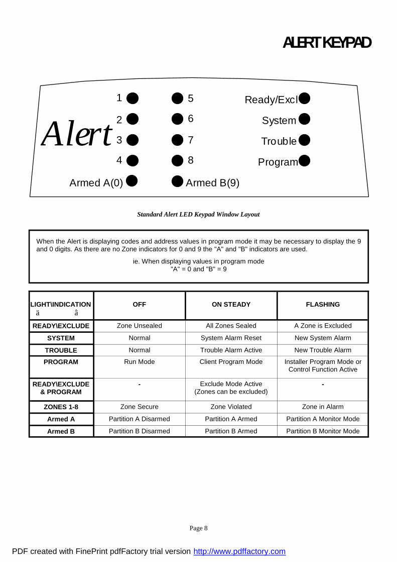
ALERT KEYPAD
When the Alert is displaying codes and address values in program mode it may be necessary to display the 9 and 0 digits. As there are no Zone indicators for 0 and 9 the "A" and "B" indicators are used.
ie. When displaying values in program mode "A" = 0 and "B" = 9
LIGHT\INDICATION ä â
OFF
ON STEADY
FLASHING
READY\EXCLUDE Zone Unsealed All Zones Sealed A Zone is Excluded
SYSTEM Normal System Alarm Reset New System Alarm
TROUBLE Normal Trouble Alarm Active New Trouble Alarm
PROGRAM Run Mode Client Program Mode Installer Program Mode or Control Function Active
READY\EXCLUDE & PROGRAM
- Exclude Mode Active (Zones can be excluded)
-
ZONES 1-8 Zone Secure Zone Violated Zone in Alarm
Armed A Partition A Disarmed Partition A Armed Partition A Monitor Mode
Armed B Partition B Disarmed Partition B Armed Partition B Monitor Mode
1
2
3
4
5
6
7
8
Ready/Excl
System
Trouble
Program
Alert
Armed A(0) Armed B(9)
Standard Alert LED Keypad Window Layout
PDF created with FinePrint pdfFactory trial version http://www.pdffactory.com
Page 9
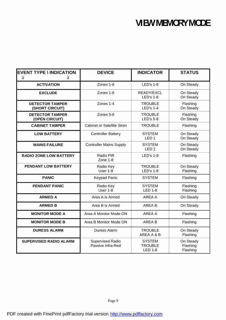
EVENT TYPE \ INDICATION ä â
DEVICE INDICATOR STATUS
ACTIVATION Zones 1-8 LED's 1-8 On Steady
EXCLUDE
Zones 1-8 READY/EXCL LED's 1-8
On Steady On Steady
DETECTOR TAMPER (SHORT CIRCUIT)
Zones 1-4 TROUBLE LED's 1-4
Flashing On Steady
DETECTOR TAMPER (OPEN CIRCUIT)
Zones 5-8 TROUBLE LED's 5-8
Flashing On Steady
CABINET TAMPER Cabinet or Satellite Siren TROUBLE Flashing
LOW BATTERY Controller Battery SYSTEM LED 1
On Steady On Steady
MAINS FAILURE Controller Mains Supply SYSTEM LED 2
On Steady On Steady
RADIO ZONE LOW BATTERY Radio PIR Zone 1-8
LED's 1-8 Flashing
PENDANT LOW BATTERY Radio Key User 1-8
TROUBLE LED's 1-8
On Steady Flashing
PANIC Keypad Panic SYSTEM Flashing
PENDANT PANIC Radio Key User 1-8
SYSTEM LED 1-8
Flashing Flashing
ARMED A Area A is Armed AREA A On Steady
ARMED B Area B is Armed AREA B On Steady
MONITOR MODE A Area A Monitor Mode ON AREA A Flashing
MONITOR MODE B Area B Monitor Mode ON AREA B Flashing
DURESS ALARM Duress Alarm TROUBLE AREA A & B
On Steady Flashing
SUPERVISED RADIO ALARM Supervised Radio Passive Infra-Red
SYSTEM TROUBLE LED 1-8
On Steady Flashing Flashing
VIEW MEMORY MODE
PDF created with FinePrint pdfFactory trial version http://www.pdffactory.com
Page 10
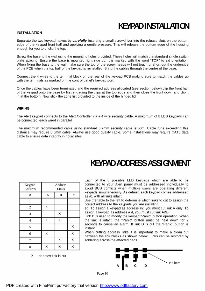
KEYPAD INSTALLATION INSTALLATION Separate the two keypad halves by carefully inserting a small screwdriver into the release slots on the bottom edge of the keypad front half and applying a gentle pressure. This will release the bottom edge of the housing enough for you to unclip the top. Screw the base to the wall using the mounting holes provided. These holes will match the standard single switch plate spacing. Ensure the base is mounted right side up. It is marked with the word "TOP" to aid orientation. When fixing the base to the wall make sure the top of the screw heads will not touch or short out the underside of the PCB when the top half of the keypad is reinstalled. Bring the cables through the centre of the base. Connect the 4 wires to the terminal block on the rear of the keypad PCB making sure to match the cables up with the terminals as marked on the control panel's keypad port. Once the cables have been terminated and the required address allocated (see section below) clip the front half of the keypad onto the base by first engaging the clips at the top edge and then close the front down and clip it in at the bottom. Now stick the zone list provided to the inside of the hinged lid. WIRING The Alert keypad connects to the Alert Controller via a 4 wire security cable. A maximum of 8 LED keypads can be connected, each wired in parallel. The maximum recommended cable using standard 0.2mm security cable is 50m. Cable runs exceeding this distance may require 0.5mm cable. Always use good quality cable. Some installations may require CAT5 data cable to ensure data integrity in noisy sites.
Keypad Address
Address Links
# A B C
1
2 X
3 X
4 X X
5 X
6 X X
7 X X
8 X X X
X denotes link is cut
Each of the 8 possible LED keypads which are able to be connected to your Alert panel must be addressed individually to avoid BUS conflicts when multiple users are operating different keypads simultaneously. As default, each keypad comes addressed as #1 with all links intact. Use the table to the left to determine which links to cut to assign the correct address to the keypads you are installing. eg. To assign a keypad as address #2, you must cut link A only. To assign a keypad as address # 4, you must cut link A&B. Link D is used to modify the keypad “Panic” button operation. When the link is intact, the “Panic” button must be held down for 2 seconds to cause an alarm. If link D is cut the “Panic” button is instant. When cutting address links it is important to make a clean cut between the link blocks as shown below. Links can be restored by soldering across the effected pads.
A B C D cut here
KEYPAD ADDRESS ASSIGNMENT
PDF created with FinePrint pdfFactory trial version http://www.pdffactory.com

Page 11
KEYPAD FUNCTIONS The Alert LED Keypad consists of; an 18 button, backlit silicone rubber keypad, 14 LED indicators and an internal piezo buzzer housed in a modern white plastic housing. The plastic housing has a hinged front lid to cover and protect the rubber buttons when not in use. All the electronics are contained on a single circuit board inside the housing. Because the keypads communicate with the controller using data, the cable run from panel to keypads is secure against tampering. For this reason there is no tamper switch on the keypad assembly. Access to the keypad electronics will not disarm the panel. BUTTONS The 18 silicone rubber buttons are used for the following functions. In normal operating mode the numeric keys are used for entering Access Codes. In Program Mode the numeric keys are used for entering options & new values. The buttons with text labels are used as function buttons and select the options indicated by the text and normally precede other button presses, e.g. to enter Exclude Mode press <EXCLUDE> and the numeric key corresponding to the zone number you wish to be excluded. The PROGRAM Key is used to prefix option selections in the program modes e.g.<PROGRAM> 4 <ENTER> selects User Code 4. The PROGRAM key is also used prior to a Master Code to enter user program mode from normal operating mode. The ENTER Key is used to enter access or program codes. It is normally used at the end of a button sequence. The CONTROL button, if enabled, is used to isolate Day zone audible Alarms if temporarily not required. LED INDICATORS The LED indicators are used to display system conditions including Zone status, Battery state, Tamper etc. Please refer to the LED tables on pages 8 & 9 for a full explanation of the conditional displays.
INSTALLING RX-16 RADIO RECEIVER The Alert V8 is fully high level compatible with the new RX-16 radio receiver. The addition of this receiver will add wireless capability to your system in the form of wireless PIR detectors, Wireless Radiokey transmitters and wireless reed switch transmitters. The RX-16 receiver connects to the same communications port as the keypads and can be installed , either inside the cabinet, or if preferred, may be installed at a remote location. The RX-16 is available in 3 frequencies,303.875mhz ,433.92mhz or 27mhz. The RX-16 receiver requires 4 cores and can successfully be run in 0.2mm unscreened cable over a distance of up to 100metres. Like the keypads the RX-16 has 12v connections labelled POS and NEG which are wired to the 12v supply and CLK and DATA terminals for connection to the communications bus. The green LED fitted to the RX-16 receiver will indicate when the unit is in "Learn" mode (Flashing - see P601E) or when it is receiving an actual radio transmission (On Steady)
PDF created with FinePrint pdfFactory trial version http://www.pdffactory.com

Page 12
PROGRAMMING YOUR ALERT HOW TO PROGRAM The programming sequence always follows this pattern;
<PROGRAM> - <1,2 or 3 digit address> - <ENTER> 3 short beeps if OK - 1 long beep if error The leds will display current value or status
Enter the new value or option <New Value> - <ENTER>
3 short beeps if OK - 1 long beep if error Throughout this manual you will see program instructions expressed as
P 10 E 5 E as an example.
In this example the <P> represents the PROGRAM key and <E>represents the ENTER key. ACCESS TO PROGRAMMING ON POWER UP (INSTALLER MODE) When power is applied to the controller for the first time, with the panel tamper input open, the panel will inhibit tamper alarms and ready the panel to enter INSTALLER PROGRAM Mode (unless the Installer Lock-out option P170E2E has previously been enabled). At this point you can go to any keypad which is connected to the panel and press “PROGRAM” “ENTER” which will automatically put that keypad into full Program mode.(NOTE:Only one keypad can be in Program mode at any time) ACCESS TO INSTALLER PROGRAM MODE FROM RUN MODE Before you can enter Installer program mode, the panel must not be set or in monitor mode.
Press <PROGRAM> - <Code 11(Installer Code)> - <ENTER> Program light will Flash
Note: Default Installer Code (Code 11) is 000000. You are now in Installer Program Mode. Any program addresses may be viewed or changed in this mode. ACCESS TO CLIENT PROGRAM MODE FROM RUN MODE
Press <PROGRAM> - <User Code> - <ENTER> Program light On Steady
Note: Default User Code (P1) is 123.
You are now in Client Program Mode. Only User Codes 1-10 can be viewed or changed in this mode. Codes may be denied access to Client mode, allowed access to change their code only or allowed access to view & change all user codes. RESETTING BACK TO FACTORY DEFAULT SETTINGS (From Install Mode Only) This address allows you to reset the panel back to the factory defaults (Reset todefaults). e.g.To reset All System defaults including User Codes (P620 E)
Press <PROGRAM> - 620 - <ENTER> 3 beeps - Program light flashing
After the system configuration has been reset back to defaults, all values, options & Codes will be set to the values shown in the Program Option Summary as defaults. These value & option selections have been chosen as the most common set-up for the majority of systems.
PDF created with FinePrint pdfFactory trial version http://www.pdffactory.com

Page 13
TO EXIT PROGRAM MODES To exit program modes when you have finished programming:
Press <PROGRAM> - <ENTER> Program light goes out
The panel is now back in Run Mode, any program changes you have made will have replaced previous values and be in effect. Note: During programming Tampers and 24 hour alarms are disabled which allows quiet access to the panel, detectors and satellite siren units etc. On exiting program mode, all inputs are scanned and if any tampers or 24Hr alarms are present an activation will occur.
PROGRAMMING USER CODES
USER CODES - (P1E to P10E) & (P11E) There are 11 codes available in the Alert, 10 user codes and 1 install code. The user codes are located in addresses 1-10. As default, Code 1 has Master Code permissions and must be used to enter Client program mode. The Installer code is stored at address 11 and is used to access Installer Program mode. Codes 1-10 may be varied in length from 1 to 6 digits.Code 11 must be 3-6 digits. To program a User Code you must first be in client or installer program mode, then select the address from 1-10. (If there is already a code programmed at this address, it will be flashed back to you) Now enter the code then press the ENTER key.
eg. P 1 E 1234 E 3 beeps - program light On Steady or flashing
In this example we have set Code 1 ( Master Code ) to be 1234.
eg. P 5 E 567 E 3 beeps - program light On Steady or flashing
In this example we have set code 5 to be 567 To replace a code simply enter the new code in the same address as the old code. This will overwrite the previous code but maintain the user permissions as mapped to that user number. To clear or delete a code simply enter the EXCLUDE button at the address where the old code is stored.
eg. P 3 E <EXCLUDE> E 3 beeps - Program light On Steady or flashing
When flashing back codes and values Zone indicators 1-8 are used to indicate digits 1-8. The digit 0 is indicated by the "A" light and 9 is indicated by the "B" light.
USER CODE OPTIONS
Note: Where there are multiple options at one address, options 0 & 9 have been reserved. Entering a 0 at the address will turn all options off whereas entering a 9 will turn all options on.
PDF created with FinePrint pdfFactory trial version http://www.pdffactory.com

Page 14
USER CODE PERMISSIONS (Code Options) - P21E-P30E Option 1 - Code has Area A permissions Option 2 - Code has Area B permissions Option 3 - Code can Arm Area Option 4 - Code can Disarm Area Option 5 - Code can turn Monitor on Option 6 - Code can turn Monitor off Option 7 - Code can Program their own code Option 8 - Code can Program Other Codes NOTE: Options 3,4, 5 & 6 are used in conjunction with options 1 & 2 whereby options 3,4, 5 & 6 determine the functions and options 1 & 2 determine the area of operation. INSTALLER CODE - P11E This code is used to enter full Installer Program mode (Program light flashing). The default installer code is 000000. To change this code enter your new installer code at the P11E address. The new code will be flashed back to you automatically.The Program code may vary from 3-6 digits in length
PROGRAMMING OUTPUT OPTIONS (NOTE:ALL OF THE FOLLOWING OUTPUT PROGRAMMING ADDRESSES REFER TO OUTPUTS 1-4 BUT ONLY OUTPUTS 1-3 ARE FITTED ON THE NON-DIALER VERSION OF THE PANEL) OUTPUT OPTIONS A- P31E-P34E This block of addresses (P31E - P34E) are used to map output modifiers to each of the outputs available on the Alert. P31E 1E Invert output #1 - Default off 2E Flash output #1 - Default off 3E Single pulse to output #1 - Default off 4E Lockout output #1 once reset - Default off 5E Spare 6E Spare 7E Output flashes on a 24 hour zone alarm - Default off 8E Day zones linked to pulse timer - Default off Option 1 Invert Output - This option is used to invert the normal state of the output. The Alert uses open collector
type transistor switches and the default state of all outputs is off or high. When in alarm the transistor switch is turned on and the output is switched low. The invert option reverses this function.
Option 2 Flash Output - This option causes the output to turn on and off at a rate set by the pulse timer for this
output (P231E) when in alarm and is normally used to flash a lamp during an activation. Option 3 Single Pulse to Output - This option, when applied, produces a single pulse at the output during an
alarm (the pulse time is the value programmed at the output pulse timer address,P231E). Option 4 Lockout Once Reset - This option is used to limit the output to one operation per arming period. Option 5 Spare Option 6 Spare Option 7 Flash 24 hour alarm - If a 24 hour zone activates the alarm this option will cause the output to flash at
a rate equal to the value set for the pulse timer(P231E). Option 8 Day Zones Linked to Pulse Timer - Day Zones programmed to this output will pulse at the pulse timer
rate (P231E) for the duration of the day zone to output timer (P221E) P32E - P34E As per P31E above for Outputs 2-4
PROGRAMMING OUTPUT OPTIONS cont.
PDF created with FinePrint pdfFactory trial version http://www.pdffactory.com
Page 15
OUTPUT OPTIONS B - P41E - P44E In this block of addresses P41E relates to output #1, P42E relates to output #2 etc P41E 1E Pendant Panic to Output #1 2E Keypad Panic to Output #1 3E Cabinet Tamper to Output #1 4E Zone Tampers to Output #1 5E Duress Alarm to Output #1 6E Mains Fail to Output #1 7E Battery Low to Output #1 8E Spare Option 1 Pendant Panic to Output - This option is used to map the operation of the Radio Pendant panic
button to an output i.e. when the Panic button is pressed any output with this option enabled will turn on.
Option 2 Keypad Panic to Output - This option is used to map the Keypad Panic Button to an output.
Keypad Panics are generated when a user presses the Panic Button at the keypad. Option 3 Cabinet Tamper to Output - This option is used to map activations of the common Tamper Input
to an output. This common tamper input is normally used to monitor the panel cabinet and satellite tamper switches.
Option 4 Zone Tampers to Output - Where dual end-of-line resistors are being used to provide individual
zone tampers, this address is used to map the Zone Tampers to an output. Option 5 Duress Alarm to Output - This option will map the Duress Alarm to an output. Programming of the
Duress Digit is at address P240E. Option 6 Mails Fail To Output - A mains failure will be indicated at this output when option 6 is enabled at
this address. The Alarm Reset Timer must be set to “0” when be this option is used. Option 7 Low Battery - A battery Low condition will be indicated at this output when option 7 is enabled at
this address. The alarm reset timer must be set to “0” when this option is used. Option 8 - Spare P42E - P44E As per P41E above for Outputs 2-4
MAPPING ZONE ALARMS TO OUTPUTS ZONE ALARM MAPPING TO OUTPUTS - P51E - P54E When a zone is in alarm (during the ARMED state only) this block of addresses allows individual
zones to be mapped to selected outputs. The default setting is that zones 1-8 will turn on all outputs 1-4 when in alarm.
P51E Zone Alarms to Output #1. Options=Zones 1-8 (Default=1-8) P52E Zone Alarms to Output #2. Options=Zones 1-8 (Default=1-8) P53E Zone Alarms to Output #3. Options=Zones 1-8 (Default=1-8) P54E Zone Alarms to Output #4. Options=Zones 1-8 (Default=1-8)
MAPPING MONITOR ZONE ALARMS TO OUTPUTS MONITOR ZONE ALARM MAPPING TO OUTPUTS - P61E - P64E
PDF created with FinePrint pdfFactory trial version http://www.pdffactory.com

Page 16
When a Monitor Mode zone is in alarm (during the MONITOR state only) this block of addresses allows individual zones to be mapped to selected outputs. The default setting is that zones 1-8 will turn on output 2 only when a monitor mode alarm occurs.
P61E Monitor Mode Zone Alarms to Output #1. Options=Zones 1-8 (Default=None) P62E Monitor Mode Zone Alarms to Output #2. Options=Zones 1-8 (Default=1-8) P63E Monitor Mode Zone Alarms to Output #3. Options=Zones 1-8 (Default=None) P64E Monitor Mode Zone Alarms to Output #4. Options=Zones 1-8 Default=None)
MAPPING 24 HOUR ZONE ALARMS TO OUTPUT 24 HOUR ZONE ALARM MAPPING TO OUTPUTS - P71E - P74E When a 24 Hour zone is in alarm this block of addresses allows individual zones to be mapped to
selected outputs. The default setting is that zones 1-8 will turn on output 2 only when a 24 Hour alarm occurs.
P71E 24 Hour Zone Alarms to Output #1. Options=Zones 1-8 (Default=None) P72E 24 Hour Zone Alarms to Output #2. Options=Zones 1-8 (Default=1-8) P73E 24 Hour Zone Alarms to Output #3. Options=Zones 1-8 (Default=None) P74E 24 Hour Zone Alarms to Output #4. Options=Zones 1-8 Default=None)
MAPPING DAY ZONES TO OUTPUTS
DAY ZONES TO OUTPUTS - P81E - P84E When a Day zone is unsealed this block of addresses allows individual zones to be mapped to
selected outputs. The default setting is that no Day zones are mapped to any of the 4 outputs. P81E Day Zone to Output #1. Options=Zones 1-8 (Default=None) P82E Day Zone to Output #2. Options=Zones 1-8 (Default=None) P83E Day Zone to Output #3. Options=Zones 1-8 (Default=None) P84E Day Zone to Output #4. Options=Zones 1-8 Default=None)
MAPPING RADIO KEYS TO OUTPUTS RADIO KEY(PENDANT) MAPPING TO OUTPUTS - P91E - P94E When a Radio Key is to be used to operate a garage door or similar function this block of addresses
allows individual Radio Keys to be mapped to selected outputs. The default setting is that none of the 8 Radio Keys are mapped to any outputs.
P91E Radio Key to Output #1. Options=Pendant 1-8 (Default=None) P92E Radio Key to Output #2. Options=Pendant 1-8 (Default=None) P93E Radio Key to Output #3. Options=Pendant 1-8 (Default=None) P94E Radio Key to Output #4. Options=Pendant 1-8 Default=None)
PARTITION “A” OPTIONS
PARTITION “A” OPTIONS - P100E This address allows modification of how Partition “A” arming, monitor and control keys work at the keypad.
PDF created with FinePrint pdfFactory trial version http://www.pdffactory.com

Page 17
P100E 1E “ARM” button required before code to set 2E “MONITOR” button required before code to turn on Monitor Mode 3E “CODE” required to arm 4E “ARM” button can disarm system during exit delay 5E “MONITOR” button can disarm Monitor Mode at any time 6E “CONTROL” function disables day zones 7E No Exit Beeps to keypads in Monitor Mode 8E Spare Option 1 “ARM” button required before code to set - This option determines if the “ARM” button must be
pressed before a code is entered to set Area “A”. If a keypad is assigned to both Partitions, this option should be set to allow individual arming of each area. This option disables the Arm button from disarming during the exit delay.
Option 2 “MONITOR” button required before code to set - This option determines if the “MONITOR” button
must be pressed before a code is entered to set Area “A” Monitor Mode. If a keypad is assigned to both Partitions, this option should be set to allow individual arming of Monitor Mode for each area.
Option 3 “CODE” required to set - If this option is set, the “ARM” button is disabled and the panel requires a
code to arm as well as disarm. Option 4 “ARM” button can disarm during exit delay - If this option is on then the “arm” button can disarm
Partition “A” during the exit delay time with a single press of the button. If the option is off then the alarm can only be unset by a valid code, even during the exit delay time.
Option 5 “MONITOR” button can disarm Monitor Mode - This option allows the “Monitor” button to disarm
monitor mode at any time (including when Monitor Mode is fully set). If the option is off then Monitor Mode can only be unset by a valid code. This feature is only valid for keypad addresses 1 & 4 (4 being the default address for the monitor key station)
Option 6 “CONTROL” function disables day zones - This option will disable the day zone monitoring when
“Control” is on. It is used to stop day zone beeps from occurring at the keypad or an output when not needed. When the “Control” function is On the Program LED will Flash.
Option 7 No Exit Beeps to keypads in Monitor Mode - This option stops the exit beeps from occurring at all
keypads when Monitor Mode is set. Normally used for silent night arming. Option 8 Spare
PARTITION “A” OUTPUT OPTIONS PARTITION “A” OUTPUT OPTIONS - P101E - P104E This block of addresses sets a number of output options which are specific and unique to the operation of partition or Area "A". Activity in Areas "B" will have no direct effect on the options set at these addresses. P101E 1E Arm/Disarm status to output #1 2E Pendant chirps for Arm/Disarm to output #1 3E Pendant chirps for Monitor Mode On/Off to output #1 4E Pulse on Arming to output #1 5E Pulse on Disarming to output #1 6E Spare 7E Spare 8E Spare Option 1 Arm/Disarm indication to output #1 - This option will turn output #1 on when Area "A" is armed and
turn output #1 off when Area "A" is disarmed. This change of state occurs at the start of the exit delay and when the Area is disarmed. Output reset time should be set to zero.
PDF created with FinePrint pdfFactory trial version http://www.pdffactory.com

Page 18
Option 2 Pendant Chirps for Arm/Disarm to output #1 - This option will map two short pulses (Chirps) to output #1 when Area "A" is armed via a radio key (Pendant) and four short pulses to output #1 when Area "A" is disarmed again. (The length of the pulses is set by the pulse timer P231E).
Option 3 Pendant Chirps for Monitor Mode On/Off to output #1 - This option will map two short pulses
(Chirps) to output #1 when Area "A" Monitor Mode is set via a radio key (Pendant) and four short pulses to output #1 when Area "A" Monitor Mode is unset again. (The length of the pulses is set by the pulse timer P231E).
Option 4 Pulse on Arming to output #1 - This option will map a pulse to Output #1 each time Area"A" is
armed. (The length of the pulse is set by the pulse timer P231E). Option 5 Pulse on Disarming to output #1 - This option will map a pulse to Output #1 each time Area"A" is
disarmed. (The length of the pulse is set by the pulse timer P231E). Option 6 Spare Option 7 Spare Option 8 Spare
Note: P102E through P104E are as above but applied to outputs 2-4
PARTITION “B” OPTIONS PARTITION “B” OPTIONS - P110E This address allows modification of how Partition “B” arming, monitor and control keys work at the keypad. P110E 1E “ARM” button required before code to set 2E “MONITOR” button required before code to turn on Monitor Mode 3E “CODE” required to arm 4E “ARM” button can disarm system during exit delay 5E “MONITOR” button can disarm Monitor Mode at any time 6E “CONTROL” function disables day zones 7E No Exit Beeps to keypads in Monitor Mode 8E Spare Option 1 “ARM” button required before code to set - This option determines if the “ARM” button must be
pressed before a code is entered to set Area “A”. If a keypad is assigned to both Partitions, this option should be set to allow individual arming of each area. This option disables the Arm button from disarming during the exit delay.
Option 2 “MONITOR” button required before code to set - This option determines if the “MONITOR” button
must be pressed before a code is entered to set Area “A” Monitor Mode. If a keypad is assigned to both Partitions, this option should be set to allow individual arming of Monitor Mode for each area.
Option 3 “CODE” required to set - If this option is set, the “ARM” button is disabled and the panel requires a
code to arm as well as disarm. Option 4 “ARM” button can disarm during exit delay - If this option is on then the “arm” button can disarm
Partition “A” during the exit delay time with a single press of the button. If the option is off then the alarm can only be unset by a valid code, even during the exit delay time.
Option 5 “MONITOR” button can disarm Monitor Mode - This option allows the “Monitor” button to disarm
monitor mode at any time (including when Monitor Mode is fully set). If the option is off then Monitor Mode can only be unset by a valid code. This feature is only valid for keypad addresses 1 & 4 (4 being the default address for the monitor key station)
Option 6 “CONTROL” function disables day zones - This option will disable the day zone monitoring when
“Control” is on. It is used to stop day zone beeps from occurring at the keypad or an output when not needed. When the “Control” function is On the Program LED will Flash.
PDF created with FinePrint pdfFactory trial version http://www.pdffactory.com

Page 19
Option 7 No Exit Beeps to keypads in Monitor Mode - This option stops the exit beeps from occurring at all keypads when Monitor Mode is set. Normally used for silent night arming.
Option 8 Spare
PARTITION “B” OUTPUT OPTIONS PARTITION “B” OUTPUT OPTIONS - P111E - P114E This block of addresses sets a number of output options which are specific and unique to the operation of partition or Area "B". Activity in Areas "A" will have no direct effect on the options set at these addresses. P111E 1E Arm/Disarm status to output #1 2E Pendant chirps for Arm/Disarm to output #1 3E Pendant chirps for Monitor Mode On/Off to output #1 4E Pulse on Arming to output #1 5E Pulse on Disarming to output #1 6E Spare 7E Spare 8E Spare Option 1 Arm/Disarm indication to output #1 - This option will turn output #1 on when Area "B" is armed and
turn output #1 off when Area "B" is disarmed. This change of state occurs at the start of the exit delay and when the Area is disarmed. Output reset time should be set to zero.
Option 2 Pendant Chirps for Arm/Disarm to output #1 - This option will map two short pulses (Chirps) to
output #1 when Area "B" is armed via a radio key (Pendant) and four short pulses to output #1 when Area "B" is disarmed again. (The length of the pulses is set by the pulse timer P231E).
Option 3 Pendant Chirps for Monitor Mode On/Off to output #1 - This option will map two short pulses
(Chirps) to output #1 when Area "B" Monitor Mode is set via a radio key (Pendant) and four short pulses to output #1 when Area "B" Monitor Mode is unset again. (The length of the pulses is set by the pulse timer P231E).
Option 4 Pulse on Arming to output #1 - This option will map a pulse to Output #1 each time Area"B" is
armed. (The length of the pulse is set by the pulse timer P231E). Option 5 Pulse on Disarming to output #1 - This option will map a pulse to Output #1 each time Area"B" is
disarmed. (The length of the pulse is set by the pulse timer P231E). Option 6 Spare Option 7 Spare Option 8 Spare
Note: P112E through P114E are as above but applied to outputs 2-4
PROGRAMMING ZONE DOUBLING SINGLE OR DUAL ZONE INPUT (4 or 8 zones) - P120E
PDF created with FinePrint pdfFactory trial version http://www.pdffactory.com

Page 20
P120E 1-4E Single or dual zone input - This option is used to define the Alert as a 4 or 8 zone panel where options 1-4 represent zone inputs 1-4. If a zone is optioned on at this address it means that zone has been assigned "Zone Doubling" whereby the one zone input is used for both a low (1-4)and a high (5-8) zone. When zone doubling is used, zone 1 input is used for zones 1 & 5, zone 2 input is used for zones 2 & 6, zones 3 input is used for zones 3 & 7 and zone 4 input is used for zones 4 & 8 . Zone doubling is assigned on a zone-by-zone basis. Enabling zone doubling automatically enables tamper monitoring for the input.
PROGRAMMING ZONE OPTIONS
PROGRAMMING ZONE OPTIONS- P121E-P134E This block of addresses (P121E - P134E) are used to select the desired functions for Zones 1-8 P121E Partition “A” Zones Zones 1-8. (Default = All 8 zones) (This option allows programming of which zones will be assigned to Partition A. If a zone is in Both A & B then it becomes common to both Areas) P122E Partition “B” Zones Zones 1-8. (Default = No zones) (This option allows programming of which zones will be assigned to Partition B. If a zone is in Both A & B then it becomes common to both Areas) P123E Zone is NC or NO Zones 1-8. (Default = All Zones NC, Normally Closed) (This option only applies to a zone that has been doubled e.g. P120E 1E doubling zone 1 input turning zone 5 on. In this example, the panel is looking to see a normally closed relay contact across the low (4K7) and high (8K2) resistors in the sealed state. By turning the LED off for zone 1, the panel is now looking for a Normally Open (NO) contact on the low zone (4K7).) P124E Radio Zone Input Zones 1-8. (Default = No zones) (This option allows programming of which zones will be radio zones. If a zone is a radio zone, the panel ignores the state of the hardwired input for that zone). If the zone input has been set to Zone doubling, the tampers are still active even if both the low & high zones are set for Radio operation. P125E Manually excludable Zone Zones 1-8. (Default = All 8 zones) (This option allows programming of which zones can be manually excluded prior to Arming. If a zone has this option turned off, then that zone cannot be excluded manually). Zones are excluded during the disarm state and normal zones which are excluded become re-included once the alarm has been set then unset. 24 hour zones, however remain excluded until manually re-included again. Every time the alarm is set or unset with zones excluded, the keypad will respond with a long beep instead of the normal 3 short beeps to indicate that excludes are present. When excluding zones, the READY\EXCL & PROGRAM leds are on to indicate that you have entered exclude mode. After excluding zones the READY\EXCL led will flash when all zones are sealed to indicate that zones are excluded. P126E Auto-excludable Zone Zones 1-8. (Default = All 8 zones) (This option allows programming of which zones can be automatically excluded at the end of the exit delay if unsealed at that time. If a zone has this option turned off, then that zone will not auto-exclude and will go into alarm if not sealed) P127E Handover Zone Zones 1-8. (Default = No zones) This option allows programming of which zones will be handover zones. If a zone is a handover zone then it’s entry delay time will apply provided a non-handover zone is triggered before the handover zone. If no other entry delays are active when the handover zone is triggered, the zone will activate immediately) P128E Two Trigger Zone Zones 1-8. (Default = No zones) (This option allows programming of which zones will require two triggers before they activate. To cause an activation a two trigger zone must alarm twice within the 2 trigger time period, P239E, or 2 two trigger zones can alarm once each within the two trigger time period before the alarm is generated. If a two trigger zone is unsealed and remains unsealed for a period longer than the two trigger time period, an alarm will also be generated)
PDF created with FinePrint pdfFactory trial version http://www.pdffactory.com

Page 21
P129E Monitor Mode Zone Zones 1-8. (Default = Zone 1) (This option allows programming of which zones can be assigned as Monitor Mode Zones. Only zones programmed at this address will be active when monitor mode is armed) P130E 24 Hour Zone Zones 1-8. (Default = No zones) (This option allows programming of which zones can be assigned as 24 Hour Zones. Only zones programmed at this address will be active at all times. If a 24 hour zone has an entry delay assigned to it, the entry delay acts as an abort timer e.g. the zone must be in alarm longer than the entry delay time before the alarm is activated. If the zone is sealed before the entry delay expires, no alarm is generated) P131E Lockout Zone Zones 1-8. (Default = No zones) (This option allows programming of which zones can be assigned as Lockout Zones. A Lockout Zone will only cause the alarm output to sound once during an armed period. If the lockout function is not programmed then the zone can cause the audible alarms to sound on every zone alarm) P132E Day Zone when Disarmed Zones 1-8. (Default = No zones) (This option allows programming of which zones can be assigned as Day Zones. A Day Zone can be used as a door minder in a shop to warn when a customer has entered the premises. A day zone has the day zone function when the alarm is disarmed, but becomes a normal security zone when armed). Day zones can be temporarily disabled with the “Control” button if programmed to do so. P133E Permanent Day Zone Zones 1-8. (Default = No zones) This option allows programming of which zones can be assigned as Permanent Day Zones. A Permanent Day Zone can be used as a door minder in a shop to warn when a customer has entered the premises. A Permanent day zone will never cause an activation when the alarm is armed). Day zones can be temporarily disabled with the “Control” button if programmed to do so. P134E Can Arm if not Sealed Zones 1-8. (Default = No zones) This option allows programming of which zones can be unsealed and still allow the panel to arm. Option 4 at P170E must be on before this address has any effect. This option allows setting of the panel if low security areas are not sealed at the time of arming)
PROGRAMMING ENTRY DELAYS P201E Zone 1 Entry Delay Time - 0-99 Seconds (Default = 20 Sec) P202E Zone 2 Entry Delay Time - 0-99 Seconds (Default = 0 Sec) P203E Zone 3 Entry Delay Time - 0-99 Seconds (Default = 0 Sec) P204E Zone 4 Entry Delay Time - 0-99 Seconds (Default = 0 Sec) P205E Zone 5 Entry Delay Time - 0-99 Seconds (Default = 0 Sec) P206E Zone 6 Entry Delay Time - 0-99 Seconds (Default = 0 Sec) P207E Zone 7 Entry Delay Time - 0-99 Seconds (Default = 0 Sec) P208E Zone 8 Entry Delay Time - 0-99 Seconds (Default = 0 Sec)
PROGRAMMING EXIT DELAYS P209E Partition “A” Exit Delay Time - 0-99 Seconds (Default = 20 Sec) P210E Partition “B” Exit Delay Time - 0-99 Seconds (Default = 20 Sec)
PROGRAMMING TWO TRIGGER TIMER P239E Two Trigger Timer - 0-99 Seconds (Default = 60 Sec)
DAY MODE TO KEYPAD BUZZER TIMER These addresses can be programmed to have a value from 0 to 99 but the value is in 1/10 of a
second increments. This means the default of 20 at addresses P219E & P220E is equal to 2 seconds. This gives a much greater control on the duration of the day zone beep to the keypad.
PDF created with FinePrint pdfFactory trial version http://www.pdffactory.com

Page 22
P219E Area “A” Day Mode to Keypad Buzzer Timer - 0-99 (Default = 20 1/10th sec) P220E Area “B” Day Mode to Keypad Buzzer Timer - 0-99 (Default = 20 1/10th sec)
OUTPUT TIMING OPTIONS OUTPUT RESET TIME-P301E-P304E (0-600 Seconds) The output reset time is how long an output will stay on following an alarm condition. P301E Output 1 Alarm Reset Time - (Default = 600 Sec) P302E Output 2 Alarm Reset Time - (Default = 600 Sec) P303E Output 3 Alarm Reset Time - (Default = 600 Sec) P304E Output 4 Alarm Reset Time - (Default = 600 Sec) OUTPUT DELAY ON TIME-P211E-P214E (0-600 Seconds) The output delay ON time is how long an output will be delayed before turning on following an alarm
condition. P211E Output 1 Delay On Time - (Default = 0 Sec) P212E Output 2 Delay On Time - (Default = 0 Sec) P213E Output 3 Delay On Time - (Default = 0 Sec) P214E Output 4 Delay On Time - (Default = 0 Sec) OUTPUT DAY MODE TIME-P221E-P224E (0-99 1/10th Second) The output day mode timer is how long an output will turn on following a day zone unsealing. The
Day Mode Timer is in 1/10th Sec intervals eg 20=2 Seconds P221E Output 1 Day Mode Time - (Default = 20) P222E Output 2 Day Mode Time - (Default = 20) P223E Output 3 Day Mode Time - (Default = 20) P224E Output 4 Day Mode Time - (Default = 20) OUTPUT PULSE TIMER-P231E-P234E (0-99 1/10th Second) The output pulse timer is how long an output will turn on when the pulse timer is used. The Pulse
Timer is in 1/10th Sec intervals eg 20=2 Seconds P231E Output 1 Pulse Timer - (Default = 20) P232E Output 2 Pulse Timer - (Default = 20) P233E Output 3 Pulse Timer - (Default = 20) P234E Output 4 Pulse Timer - (Default = 20)
RADIO ZONE CODE LOAD
To load a radio device as a zone input on the panel, press the appropriate address number (eg P604E for Zone 4). The keypad buzzer will beep once a second to indicate learn mode has been initiated and the Led on the RX-16 board will flash. The radio device you wish to load must transmit a signal within 30 seconds of entering learning mode otherwise the panel will time out and no code will be loaded. If a valid code is received within the 30 seconds the keypad will give 3 short beeps and
PDF created with FinePrint pdfFactory trial version http://www.pdffactory.com

Page 23
exit learn mode. To remove a loaded radio code at a single address only, enter in the code load address as above eg P604E, then without operating the transmitter and before the 30 second timer expires press the “Enter” button. This will remove the code loaded against this address (in this case radio zone 4).
P601E Load Radio Code for Zone 1 P602E Load Radio Code for Zone 2 P603E Load Radio Code for Zone 3 P604E Load Radio Code for Zone 4 P605E Load Radio Code for Zone 5 P606E Load Radio Code for Zone 6 P607E Load Radio Code for Zone 7 P608E Load Radio Code for Zone 8
RADIO ZONE DETECTOR OPTIONS
RADIO ZONE DETECTOR OPTIONS- P141E-P148E This block of addresses (P141E - P148E) are used to select the type of detector to be used on the radio zone input and allow functions such as battery low, tamper and normal alarm to be correctly recognized. To make the radio zone work you must also tell the zone input that it is a radio zone (P124E-zones 1-8). P141E-Zone 1 Options 1E Ness Battery Low 2E Ness Radio Reed Switch 3E Crow Battery Low 4E Crow Radio Reed Switch 5E Visonic Radio PIR 6E Electronics Line Radio PIR 7E Crow Supervised Detectors 8E Spare Option 1 Ness Battery Low - If a Ness radio pendant or PIR is used on the Alert radio zone input, setting
this bit allows the panel to correctly recognize the battery low signal from Ness devices. Option 2 Ness Radio Reed Switch - If a Ness radio reed switch is used on the Alert radio zone input, setting
this bit allows the panel to correctly recognize the battery low signal from the Ness device. This bit also recognizes the open and closed signals from the reed switch so the zone Led can follow the correct state of the reed switch (ie open or closed)
Option 3 Crow Battery Low - If a Crow radio pendant or PIR is used on the Alert radio zone input, setting
this bit allows the panel to correctly recognize the battery low signal from Crow devices. Option 4 Crow Radio Reed Switch - If a Crow radio reed switch is used on the Alert radio zone input,
setting this bit allows the panel to correctly recognize the battery low signal from the Crow device. This bit also recognizes the open and closed signals from the reed switch so the zone Led can follow the correct state of the reed switch (ie open or closed)
Option 5 Visonic Radio PIR - If a Visonic radio PIR is used on the Alert radio zone input, setting this bit
allows the panel to correctly recognize the alarm, tamper & battery low signal from the Visonic device.
Option 6 Electronics Line Radio PIR- If an Electronics Line radio PIR is used on the Alert radio zone input,
setting this bit allows the panel to correctly recognize the alarm, tamper & battery low signal from the EL device.
Option 7 Crow Supervised Devices- If a Supervised Crow radio PIR or smoke detector is used on the
Alert radio zone input, setting this bit allows the panel to correctly recognize the alarm, tamper & battery low signal from Crow supervised devices. The Crow supervised devices automatically transmit a supervision signal every 5 minutes. If the panel does not see at least one supervision signal from each device connected to the Alert within a 20 minute period, an alarm is generated.
PDF created with FinePrint pdfFactory trial version http://www.pdffactory.com

Page 24
The alarm will cause the System Led to flash and the alarm will go into memory for displaying at a later time.
Option 8 Spare
Note: P142E through P148E are as above but applied to zones 2-8
RADIO PENDANT CODE LOAD To load a radio pendant on the panel, press the appropriate address number (e.g. P614E for
Pendant 4). The keypad buzzer will beep once a second to indicate learn mode has been initiated and the Led on the RX-16 board will flash. The radio pendant you wish to load must transmit a signal within 30 seconds of entering learning mode otherwise the panel will time out and no code will be loaded. If a valid code is received within the 30 seconds the keypad will give 3 short beeps and exit learn mode. To remove a loaded radio pendant at a single address only, enter in the code load address as above eg P614E, then without operating the transmitter and before the 30 second timer expires press the “Enter” button. This will remove the code loaded against this address (in this case radio pendant 4).
P611E Load Radio Pendant # 1 P612E Load Radio Pendant # 2 P613E Load Radio Pendant # 3 P614E Load Radio Pendant # 4 P615E Load Radio Pendant # 5 P616E Load Radio Pendant # 6 P617E Load Radio Pendant # 7 P618E Load Radio Pendant # 8
RADIO PENDANT OPTIONS “A” RADIO PENDANT OPTIONS “A”- P151E-P158E This block of addresses (P151E - P158E) are used to select the operational settings for each of the 8 radio pendants. Functions such as arm only, disarm only or both can be selected for each pendant independently. P151E-Pendant #1 Options 1E Assigned to Partition “A” 2E Assigned to Partition “B” 3E Pendant can Arm the system 4E Pendant can Disarm the system 5E Pendant can turn Monitor Mode On 6E Pendant can turn Monitor Mode Off 7E Spare 8E Pendant is disabled if panel is in alarm Option 1 Assigned to Partition “A” - This option assigns the pendant to partition “A”. The pendant must be
assigned to at least one partition to allow it to perform arm/disarm functions. The pendant can be assigned to both partitions if required.
Option 2 Assigned to Partition “B” - This option assigns the pendant to partition “B”. The pendant must be
assigned to at least one partition to allow it to perform arm/disarm functions. The pendant can be assigned to both partitions if required.
Option 3 Pendant can Arm - This option assigns the Arm function to a pendant. The partition/s it will arm has
to be selected at options 1 & 2. Option 4 Pendant can Disarm - This option assigns the Disarm function to a pendant. The partition/s it will
disarm has to be selected at options 1 & 2. Option 5 Pendant can turn Monitor Mode On - This option assigns the Monitor Mode Arm function to a
pendant. The partition/s it will arm has to be selected at options 1 & 2. If Monitor Mode arming is to be used for this pendant then Options 2 & 3 should be turned off.
Option 6 Pendant can turn Monitor Mode Off - This option assigns the Monitor Mode Disarm function to a
PDF created with FinePrint pdfFactory trial version http://www.pdffactory.com

Page 25
pendant. The partition/s it will disarm has to be selected at options 1 & 2. If Monitor Mode disarming is to be used for this pendant then Options 2 & 3 should be turned off.
Option 7 Spare Option 8 Pendant Disabled if panel is in Alarm - This option stops the pendant from working while the panel
is in alarm. This feature should only be set if you feel that a pendant with disarming functions could be prone to misuse in an alarm condition.
Note: P152E through P158E are as above but applied to pendants 2-8
RADIO PENDANT OPTIONS “B” RADIO PENDANT OPTIONS “B”- P161E-P168E This block of addresses (P161E - P168E) are used to select output control and Panic options for each of the 8 radio pendants. To prevent confusion, if a pendant is set to control an output or provide instant Panic, then you should turn off any Arm or Disarm options at addresses P151E-P158E. P161E-Pendant #1 Options 1E Turn output ON 2E Turn output OFF 3E Spare 4E Spare 5E Spare 6E Immediate Panic Alarm 7E Delayed Panic Alarm (1.5 Seconds) 8E Ness Battery Low Option 1 Turn Output On - This option allows the pendant to turn an output on. The output the pendant will
turn On is programmed at address P91E-P94E. If the output reset time is set to Latched operation (set to “0”) then you must also program Option 2 to the pendant to allow for turning the output Off.
Option 2 Turn Output Off - This option allows the pendant to turn an output off. The output the pendant will
turn Off is programmed at address P91E-P94E. For this option to work, option 1 above must also be assigned to the pendant to allow the pendant to first turn the output on before it can turn it off.
Option 3 Spare Option 4 Spare Option 5 Spare Option 6 Immediate Panic Alarm - If this option is on, pressing the pendant button will produce a pendant
panic alarm. Option 7 Delayed Panic Alarm- If this option is on, the pendant button must be pressed continuously 1.5
seconds or longer to produce a pendant panic alarm. Option 8 Ness Battery Low - If using a Ness pendant with battery low reporting, this option must be turned on
to allow the battery low signal to be recognized properly.,
Note: P152E through P158E are as above but applied to pendants 2-8
KEYPAD PARTITION OPTIONS A keypad must be assigned to a Partition before it can control the Partition (ie to allow Arm/Disarm facilities). P171E Keypads Assigned to Partition “A” - Option Keypad 1-8 P172E Keypads Assigned to Partition “B” - Option keypad 1-8
PDF created with FinePrint pdfFactory trial version http://www.pdffactory.com

Page 26
KEYPADS WITH PANIC BUTTON ENABLED The panic button on all keypads can be set to an instant operation or a 2 second delayed operation (see
page 10). As well as the keypad options, the panel can enable or disable the panic button at each of the potential 8 keypad. This option may be useful where a keypad has to be installed in a public area.
P173E Keypads with the Panic Button Enabled - Option keypad 1-8
MISCELLANEOUS PANEL OPTIONS This address (P170E) is used to select optional miscellaneous panel functions. P170E 1E Panel Tamper NC or EOL 2E Installer Lockout 3E Disable Mains Fail Test 4E Arm only if Sealed 5E No audible keypad beep on supervised radio fault 6E Spare 7E Spare 8E Spare Option 1 Panel Tamper NC or EOL - The Tamper input on the Alert control board (Tmp) requires sealing to clear
the panel tamper alarm. If option 1 is on the panel must see a 2k2 resistor (EOL) across the Tmp & 0V terminals to ensure the tamper is sealed. If this option is turned off the a simple short circuit (NC) is all that is required to seal the panel tamper.
Option 2 Installer Lockout - Normally, if the panel is unset and powered up with the panel tamper open (in
alarm) then the panel will allow access to installer program mode by pressing the “Program” then “enter” buttons at any keypad connected to the system. If this option is on, the panel will not allow access to program mode and the only valid method of accessing program mode is via the installer code.
Option 3 Disable Mains Fail Test - If the panel must be run off a DC supply but the supply is too low to be wired
into the AC terminals then this option completely disables the mains fail monitoring so the panel will not give a continuous system alarm.
Option 4 Arm only if Sealed - If this option is on then the panel can only be armed if all zones are sealed
( excluding those zones which can be ignored at address P134E) Option 5 No audible keypad beep on supervised radio fault - If a supervised radio detector fails to send a test
signal within a 20 minute period, an alarm will be generated in the form of the system LED on the keypad will flash. If this option is off then all keypad buzzers will also sound continuously to warn of the problem. If this option is on, the buzzers will not sound on a supervised alarm but the system LED will still flash.
Option 6 Spare Option 7 Spare Option 8 Spare
DURESS DIGIT
This address (P240E) is used to program the duress digit. The duress digit is a number from 1-9 (“0” means the duress function is disabled) .To create a duress alarm the duress digit must be entered before a valid user code (eg If the code was “123” and the duress number was “4”, then entering a code of “4123” “Enter” would create a duress alarm).
PDF created with FinePrint pdfFactory trial version http://www.pdffactory.com

Page 27
P240E Duress Digit - Value 1-9 (Default = 0, Disabled)
RESTORE FACTORY DEFAULTS This address (P620E) is used to return the panel back to factory default settings. P620E Restore Factory Defaults
CLEAR ALARM MEMORY BUFFER This address (P621E) is used to clear the panels alarm memory buffer. P621E Clear Alarm Memory Buffer
WALK TEST MODE This address (P622E) is used to enable walk-test mode while in installer program mode. By pressing
P622E at the keypad, the keypad buzzer will beep at 1 second intervals to indicate walk-test mode is active. By walking past all of the detectors connected to the system and activating them, the associated zone light will latch up at the keypad to allow verification that all zones are working properly. By pressing the “Program” or “Enter” buttons, walk-test mode can be terminated and normal programming resumed.
P622E Walk-test Mode
ALERT PROGRAM SUMMARY GUIDE The following program summary is an abbreviated version of all the Alert program addresses. This is intended as a quick guide to finding a program address. The program addresses are in numerical order with page references beside them so you can get more detailed information if required.
Programming User Codes
PDF created with FinePrint pdfFactory trial version http://www.pdffactory.com

Page 28
P1E User Code # 1 - Default = 123 Page 13 P2E User Code # 2 Page 13 P3E User Code # 3 Page 13 P4E User Code # 4 Page 13 P5E User Code # 5 Page 13 P6E User Code # 6 Page 13 P7E User Code # 7 Page 13 P8E User Code # 8 Page 13 P9E User Code # 9 Page 13 P10E User Code # 10 Page 13 P11E Installer Code. Code # 11 - Installer Code ( Default = 000000) Page 13
User Code Options P21E User Options Code # 1 (Default 1-8) P21E-P30E Options Page 14 P22E User Options Code # 2 (Default 1-6) 1 = Assigned to Area “A” Page 14 P23E User Options Code # 3 (Default 1-6) 2 = Assigned to Area “B” Page 14 P24E User Options Code # 4 (Default 1-6) 3 = Code can Arm Area Page 14 P25E User Options Code # 5 (Default 1-6) 4 = Code can Disarm Area Page 14 P26E User Options Code # 6 (Default 1-6) 5 = Code can arm Monitor Mode Page 14 P27E User Options Code # 7 (Default 1-6) 6 = Code can disarm Monitor Mode Page 14 P28E User Options Code # 8 (Default 1-6) 7 = User can Change their Code Page 14 P29E User Options Code # 9 (Default 1-6) 8 = User can Change Codes 1-10 Page 14 P30E User Options Code # 10 (Default 1-6) Page 14
Programming Output Options “A” P31E Options for Output # 1 (Default None) P31E-P34E Options Page 14 P32E Options for Output # 2 (Default None) 1 = Invert Output Page 14 P33E Options for Output # 3 (Default None) 2 = Flash Output Page 14 P34E Options for Output # 4 (Default None) 3 = Single Pulse to Output Page 14 4 = Lockout Output 5 = Spare 6 = Spare 7 = Output Flashes on 24 Hour Alarm 8 = Day zones linked to Pulse Timer
Programming Output Options “B” P41E Options for Output # 1 (Default 1-4) P41E-P44E Options Page 15 P42E Options for Output # 2 (Default 1-4) 1 = Pendant Panic to Output Page 15 P43E Options for Output # 3 (Default 1-4) 2 = Keypad Panic to Output Page 15 P44E Options for Output # 4 (Default 1-4) 3 = Cabinet Tamper to Output Page 15 4 = Zone Tampers to output 5 = Duress Alarm to Output 6 = Mains Fail to Output 7 = Battery Low to output 8 = Spare
Mapping Zone Alarms To Outputs P51E Normal Zone Alarms 1-8 to Output # 1 (Default= All Zones) Page 15 P52E Normal Zone Alarms 1-8 to Output # 2 (Default= All Zones) Page 15 P53E Normal Zone Alarms 1-8 to Output # 3 (Default= All Zones) Page 15 P54E Normal Zone Alarms 1-8 to Output # 4 (Default= All Zones) Page 15
Mapping Monitor Zone Alarms To Outputs P61E Monitor Mode Zone Alarms 1-8 to Output # 1 (Default= None) Page 16 P62E Monitor Mode Zone Alarms 1-8 to Output # 2 (Default= All Zones) Page 16 P63E Monitor Mode Zone Alarms 1-8 to Output # 3 (Default= None) Page 16 P64E Monitor Mode Zone Alarms 1-8 to Output # 4 (Default= None) Page 16
Mapping 24 Hour Zone Alarms To Outputs
PDF created with FinePrint pdfFactory trial version http://www.pdffactory.com

Page 29
P71E 24 Hour Zone Alarms 1-8 to Output # 1 (Default= None) Page 16 P72E 24 Hour Zone Alarms 1-8 to Output # 2 (Default= All Zones) Page 16 P73E 24 Hour Zone Alarms 1-8 to Output # 3 (Default= None) Page 16 P74E 24 Hour Zone Alarms 1-8 to Output # 4 (Default= None) Page 16
Mapping Day Zones To Outputs P81E Day Zones 1-8 to Output # 1 (Default= None) Page 16 P82E Day Zones 1-8 to Output # 2 (Default= None) Page 16 P83E Day Zones 1-8 to Output # 3 (Default= None) Page 16 P84E Day Zones 1-8 to Output # 4 (Default= None) Page 16
Mapping Radio Keys To Outputs P91E Radio Key 1-8 to Output # 1 (Default= None) Page 16 P92E Radio Key 1-8 to Output # 2 (Default= None) Page 16 P93E Radio Key 1-8 to Output # 3 (Default= None) Page 16 P94E Radio Key 1-8 to Output # 4 (Default= None) Page 16
Partition “A” Options P100E Partition “A” Options P100E Options Page 17 (Default= 4 & 5) 1 = Arm Button Required Before Code to Set 2 = Monitor Button Required Before Code to Set Monitor Mode 3 = Code required to Set 4 = Arm Button can disarm during Exit Delay 5 = Monitor Button can disarm Monitor Mode at any time 6 = Control Function disables day Zones 7 = No Exit beeps to Keypads in Monitor Mode 8 = Spare
Partition “A” Output Options P101E Area “A” Opt. O/P # 1 (Default= None) P101E-P104E Options Page 17 P102E Area “A” Opt. O/P # 2 (Default= None) 1 = Arm/Disarm Status to Output Page 17 P103E Area “A” Opt. O/P # 3 (Default= None) 2 = Pendant Chirps on Arm/Disarm Page 17 P104E Area “A” Opt. O/P # 4 (Default= None) 3 = Pendant Chirps on Monitor Mode Arm/Disarm Page 17 4 = Pulse on Arming to Output 5 = Pulse on Disarming to Output 6 = Spare 7 = Spare 8 = Spare
Partition “B” Options P110E Partition “B” Options P110E Options Page 18 (Default= 4 & 5) 1 = Arm Button Required Before Code to Set 2 = Monitor Button Required Before Code to Set Monitor Mode 3 = Code required to Set 4 = Arm Button can disarm during Exit Delay 5 = Monitor Button can disarm Monitor Mode at any time 6 = Control Function disables day Zones 7 = No Exit beeps to Keypads in Monitor Mode 8 = Spare
Partition “B” Output Options P111E Area “B” Opt. O/P # 1 (Default= None) P111E-P114E Options Page 19 P112E Area “B” Opt. O/P # 2 (Default= None) 1 = Arm/Disarm Status to Output Page 19 P113E Area “B” Opt. O/P # 3 (Default= None) 2 = Pendant Chirps on Arm/Disarm Page 19 P114E Area “B” Opt. O/P # 4 (Default= None) 3 = Pendant Chirps on Monitor Mode Arm/Disarm Page 19 4 = Pulse on Arming to Output 5 = Pulse on Disarming to Output 6 = Spare
PDF created with FinePrint pdfFactory trial version http://www.pdffactory.com
Page 30
7 = Spare 8 = Spare
Programming Zone Doubling P120E Zone Doubling - Value 1-4 (Default = All Off, ie set as a 4 zone panel only) Page 20
Programming Zone Options
P121E Partition “A” Zones Zones 1-8 ( Default = All zones) Page 20 P122E Partition “B” Zones Zones 1-8 ( Default = No zones) Page 20 P123E Zone is NC or NO Zones 1-8 ( Default = All zones are NC) Page 20 P124E Radio Zone Input Zones 1-8 ( Default = No zones) Page 20 P125E Manually excludable Zone Zones 1-8 ( Default = All zones) Page 20 P126E Auto-excludable Zone Zones 1-8 ( Default = All zones) Page 20 P127E Handover Zone Zones 1-8 ( Default = No zones) Page 20 P128E Two Trigger Zone Zones 1-8 ( Default = No zones) Page 20 P129E Monitor Mode Zone Zones 1-8 ( Default = Zone 1,2) Page 20 P130E 24 Hour Zone Zones 1-8 ( Default = No zones) Page 20 P131E Lockout Zone Zones 1-8 ( Default = No zones) Page 20 P132E Day Zone Zones 1-8 ( Default = No zones) Page 20 P133E Permanent Day Zone Zones 1-8 ( Default = No zones) Page 20 P134E Can Arm if not Sealed Zones 1-8 ( Default = No zones) Page 20
Radio Zone Detector Options P141E Options for Zone # 1 (Default= None) P141E-P148E Options Page 23 P142E Options for Zone # 2 (Default= None) 1 = Ness Battery Low Page 23 P143E Options for Zone # 3 (Default= None) 2 = Ness Radio Reed Switch Page 23 P144E Options for Zone # 4 (Default= None) 3 = Crow Battery low Page 23 P145E Options for Zone # 5 (Default= None) 4 = Crow Radio Reed Switch Page 23 P146E Options for Zone # 6 (Default= None) 5 = Visonic Radio PIR Page 23 P147E Options for Zone # 7 (Default= None) 6 = Electronics Line Radio PIR Page 23 P148E Options for Zone # 8 (Default= None) 7 = Crow Supervised Detectors Page 23 8 = Spare Page 23
Radio Pendant Options “A” P151E Radio Key # 1 Opt (Default= 1,2,3,4&8) P151E-P158E Options Page 24 P152E Radio Key # 2 Opt (Default= 1,2,3,4&8) 1 = Assigned to Area “A” Page 24 P153E Radio Key # 3 Opt (Default= 1,2,3,4&8) 2 = Assigned to Area “B” Page 24 P154E Radio Key # 4 Opt (Default= 1,2,3,4&8) 3 = Can Arm Area Page 24 P155E Radio Key # 5 Opt (Default= 1,2,3,4&8) 4 = Can Disarm Area Page 24 P156E Radio Key # 6 Opt (Default= 1,2,3,4&8) 5 = Can arm Monitor Mode Page 24 P157E Radio Key # 7 Opt (Default= 1,2,3,4&8) 6 = Can disarm Monitor Mode Page 24 P158E Radio Key # 8 Opt (Default= 1,2,3,4&8) 7 = Spare Page 24 8 = Disabled if Panel is in Alarm
Radio Pendant Options “B” P161E Radio Key # 1 Options (Default= None) P161E-P168E Options Page 25 P162E Radio Key # 2 Options (Default= None) 1 = Pendant Can Turn Output On Page 25 P163E Radio Key # 3 Options (Default= None) 2 = Pendant Can Turn Output Off Page 25 P164E Radio Key # 4 Options (Default= None) 3 = Spare Page 25 P165E Radio Key # 5 Options (Default= None) 4 = Spare Page 25 P166E Radio Key # 6 Options (Default= None) 5 = Spare Page 25 P167E Radio Key # 7 Options (Default= None) 6 = Causes Immediate Panic Page 25
PDF created with FinePrint pdfFactory trial version http://www.pdffactory.com

Page 31
P168E Radio Key # 8 Options (Default= None) 7 = Causes Delayed Panic ( 1.5 Sec) Page 25 8 = Ness Battery Low
Miscellaneous Panel Options P170E Miscellaneous Panel Options P170E Options Page 26 (Default= 5) 1 = Panel Tamper NC or EOL 2 = Installer Lockout 3 = Disable Mains Fail Test 4 = Arm only if Sealed 5 = No audible keypad beep on supervised radio fault 6 = Spare 7 = Spare 8 = Spare
Keypad Partition Options P171E Keypads Assigned To Partition “A” - Value Keypad 1-8 (Default= All Keypads) Page 26 P172E Keypads Assigned To Partition “B” - Value Keypad 1-8 (Default= No Keypads) Page 26
Keypads with Panic Button Enabled P173E Keypads with Panic Button Enabled - Value Keypad 1-8 (Default= All Keypads) Page 26
Programming Entry/Exit Delays P201E Zone 1 Entry Delay Time - Value 0-99 Seconds (Default = 20 Sec) Page 21 P202E Zone 2 Entry Delay Time - Value 0-99 Seconds (Default = 0 Sec) Page 21 P203E Zone 3 Entry Delay Time - Value 0-99 Seconds (Default = 0 Sec) Page 21 P204E Zone 4 Entry Delay Time - Value 0-99 Seconds (Default = 0 Sec) Page 21 P205E Zone 5 Entry Delay Time - Value 0-99 Seconds (Default = 0 Sec) Page 21 P206E Zone 6 Entry Delay Time - Value 0-99 Seconds (Default = 0 Sec) Page 21 P207E Zone 7 Entry Delay Time - Value 0-99 Seconds (Default = 0 Sec) Page 21 P208E Zone 8 Entry Delay Time - Value 0-99 Seconds (Default = 0 Sec) Page 21 P209E Partition “A” Exit Delay Time - Value 0-99 Seconds (Default = 20 Sec) Page 21 P210E Partition “B” Exit Delay Time - Value 0-99 Seconds (Default = 20 Sec) Page 21
Output Delay ON time P211E Output 1 Delay ON Time - Value 0-99 Seconds (Default = 0 Sec) Page 22 P212E Output 2 Delay ON Time - Value 0-99 Seconds (Default = 0 Sec) Page 22 P213E Output 3 Delay ON Time - Value 0-99 Seconds (Default = 0 Sec) Page 22 P214E Output 4 Delay ON Time - Value 0-99 Seconds (Default = 0 Sec) Page 22
Day Mode to Keypad Buzzer Timer P219E Partition “A” Day Mode to KP Buzzer Time - Value 0-99 1/10 Seconds (Default ; 20 =2 Sec) Page 22 P220E Partition “B” Day Mode to KP Buzzer Time - Value 0-99 1/10 Seconds (Default ; 20 =2 Sec) Page 22
Output Day Mode Time P221E Output 1 Day Mode ON Time - Value 0-99 1/10 Seconds (Default ; 20 =2 Sec) Page 22 P222E Output 2 Day Mode ON Time - Value 0-99 1/10 Seconds (Default ; 20 =2 Sec) Page 22 P223E Output 3 Day Mode ON Time - Value 0-99 1/10 Seconds (Default ; 20 =2 Sec) Page 22 P224E Output 4 Day Mode ON Time - Value 0-99 1/10 Seconds (Default ; 20 =2 Sec) Page 22
Output Pulse Time
PDF created with FinePrint pdfFactory trial version http://www.pdffactory.com

Page 32
P231E Output 1 Pulse Time - Value 0-99 1/10 Seconds (Default ; 20 =2 Sec) Page 22 P232E Output 2 Pulse Time - Value 0-99 1/10 Seconds (Default ; 20 =2 Sec) Page 22 P233E Output 3 Pulse Time - Value 0-99 1/10 Seconds (Default ; 20 =2 Sec) Page 22 P234E Output 4 Pulse Time - Value 0-99 1/10 Seconds (Default ; 20 =2 Sec) Page 22
Two Trigger Timer P239E Two Trigger Timer - Value 0-99 Seconds (Default = 60 Sec) Page 21
Duress Digit P240E Duress Digit - Value 1-9 (Default = 0 Duress Function Disabled) Page 27
Output Reset Time P301E Output 1 Reset Time - Value 0-9999 Seconds (Default = 600 Sec) Page 22 P302E Output 2 Reset Time - Value 0-9999 Seconds (Default = 600 Sec) Page 22 P303E Output 3 Reset Time - Value 0-9999 Seconds (Default = 600 Sec) Page 22 P304E Output 4 Reset Time - Value 0-9999 Seconds (Default = 600 Sec) Page 22
Radio Zone Code Loading P601E Load Radio Code for Zone # 1 Page 23 P602E Load Radio Code for Zone # 2 Page 23 P603E Load Radio Code for Zone # 3 Page 23 P604E Load Radio Code for Zone # 4 Page 23 P605E Load Radio Code for Zone # 5 Page 23 P606E Load Radio Code for Zone # 6 Page 23 P607E Load Radio Code for Zone # 7 Page 23 P608E Load Radio Code for Zone # 8 Page 23
Radio Pendant Code Loading P611E Load Radio Pendant Code # 1 Page 24 P612E Load Radio Pendant Code # 2 Page 24 P613E Load Radio Pendant Code # 3 Page 24 P614E Load Radio Pendant Code # 4 Page 24 P615E Load Radio Pendant Code # 5 Page 24 P616E Load Radio Pendant Code # 6 Page 24 P617E Load Radio Pendant Code # 7 Page 24 P618E Load Radio Pendant Code # 8 Page 24
Restore Factory Defaults P620E Restore Panel to Factory Defaults Page 27
Clear Alarm Memory Buffer P621E Clear Alarm Memory Buffer Page 27
Walk-Test Mode P622E Walk-Test Mode Page 27
PDF created with FinePrint pdfFactory trial version http://www.pdffactory.com

Page 33
PDF created with FinePrint pdfFactory trial version http://www.pdffactory.com

Page 34
PDF created with FinePrint pdfFactory trial version http://www.pdffactory.com

Page 35
PDF created with FinePrint pdfFactory trial version http://www.pdffactory.com