Embed Size (px)
Citation preview

SCXF-SVX01B-EN
Installation, Owner, andDiagnostic Manual
IntelliPak®
Commercial Self-ContainedSignature Series, 20-80 Ton
Models
“BO” and later Design Sequence
SCWF -020, -022, -025, -029, -032, -035, -038, -042, -046, -052, -058, -065, -072, -080SIWF -020, -022, -025, -029, -032, -035, -038, -042, -046, -052, -058, -065, -072, -080SCRF -020, -025, -029, -030, -035, -040, -050, -060SIRF -020, -025, -029, -030, -035, -040, -050, -060
May 2000
©American Standard Inc. 2000 SCXF-SVX01B-EN
GeneralInformation
About This Manual
Literature Change History
Use this manual for commercial self-contained models SCWF, SIWF, SCRF, andSIRF. This is the first revision of thismanual. It provides specific installation,owner maintenance, and diagnostictroubleshooting instructions for “BO” andlater design sequences. The “BO” designsequence includes the VFD change fromSquare D Altivar 66 to Altivar 58. Forprevious design sequences, contact yourlocal Trane representative.
Warnings and Cautions
Warnings in this manual indicate potentialhazardous situations that can result indeath or serious injury.
Cautions in this manual indicate potentialhazardous situations that may result inminor or moderate injury and/orequipment damage.
Examples:
Disconnect electrical powersource before servicing unit toprevent injury or death fromelectrical shock.
Use only copper conductors forelectrical unit connections toprevent equipment damage.
Common HVAC AcronymsFor convenience, a number of acronymsand abbreviations are used throughoutthis manual. These acronyms arealphabetically listed and defined below.
BAS = Building automation systemsCFM = Cubic-feet-per-minuteCKT. = CircuitCV = Constant volumeCW = ClockwiseCCW = CounterclockwiseE/A = Exhaust airECEM = Exhaust/comparative enthalpy
����� CAUTION!
moduleF/A = Fresh airGBAS = Generic building automationsystemHGBP = Hot gas bypassHI = Human InterfaceHVAC = Heating, ventilation and airconditioningIGV = Inlet guide vanesI/O = Inputs/outputsIOD= Installation/owner/diagnosticmanualIPC = Interprocessor communicationsIPCB = Interprocessor communicationsbridgeLH = Left-handMCM = Multiple compressor moduleMWU = Morning warmupNSB = Night setbackO/A = Outside airpsig = Pounds-per-square-inch, gaugepressureR/A = Return airRH = Right-handRPM = Revolutions-per-minuteRTM = Rooftop moduleS/A = Supply airSCM = Single circuit moduleSZ = Single-zone (unit airflow)TCI = Tracer® communications moduleUCM = Unit control modulesVAV = Variable air volumeVCM = Ventilation control moduleVOM = Ventilation override modulew.c. = Water columnWSM = Waterside moduleZSM = Zone sensor module
Special Note on RefrigerationEmissions
World environmental scientists haveconcluded that ozone in our upperatmosphere is being reduced due to therelease of CFC fully halogenatedcompounds.
The Trane Company urges all HVACservice personnel to make every effort toprevent any refrigerant emissions whileinstalling, operating, or servicing equip-ment. Always conserve refrigerants forcontinued use.
WARNING!
SCXF-SVX01B-EN 3
Contents
Cross reference to related publications/information:IntelliPak® Self-Contained Programming Guide, PKG-SVP01B-ENRemote Air-Cool-Condenser Installation, Owner, and Diagnostic Manual, CXRC-SVX01A-ENFor units with a VFD: Instruction Bulletin Altivar 58 Adjustable Speed Drive ControllersInstallation Guide, Type H Controllers Keypad Display
Installation
General InformationPre-installation ConsiderationsDimensions/WeightsMechanical RequirementsElectrical RequirementsPre-Startup Requirements
ProgrammingStartup
Owner
General InformationSequence of OperationMaintenance
Diagnostic Troubleshooting
TroubleshootingDiagnostics
4
49
1322
95
57
9695
817460
60
472826
4 SCXF-SVX01B-EN
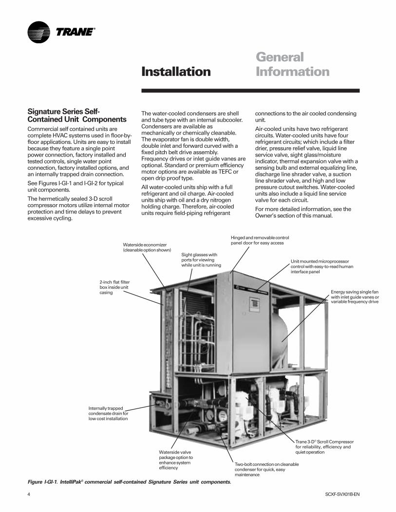
Figure I-GI-1. IntelliPak® commercial self-contained Signature Series unit components.
Installation
Signature Series Self-Contained Unit Components
Commercial self contained units arecomplete HVAC systems used in floor-by-floor applications. Units are easy to installbecause they feature a single pointpower connection, factory installed andtested controls, single water pointconnection, factory installed options, andan internally trapped drain connection.
See Figures I-GI-1 and I-GI-2 for typicalunit components.
The hermetically sealed 3-D scrollcompressor motors utilize internal motorprotection and time delays to preventexcessive cycling.
The water-cooled condensers are shelland tube type with an internal subcooler.Condensers are available asmechanically or chemically cleanable.The evaporator fan is double width,double inlet and forward curved with afixed pitch belt drive assembly.Frequency drives or inlet guide vanes areoptional. Standard or premium efficiencymotor options are available as TEFC oropen drip proof type.
All water-cooled units ship with a fullrefrigerant and oil charge. Air-cooledunits ship with oil and a dry nitrogenholding charge. Therefore, air-cooledunits require field-piping refrigerant
2-inch flat filterbox inside unitcasing
Waterside economizer(cleanable option shown)
Sight glasses withports for viewingwhile unit is running
Hinged and removable controlpanel door for easy access
Unit mounted microprocessorcontrol with easy-to-read humaninterface panel
Energy saving single fanwith inlet guide vanes orvariable frequency drive
Internally trappedcondensate drain forlow cost installation
Waterside valvepackage option toenhance systemefficiency
Two-bolt connection on cleanablecondenser for quick, easymaintenance
Trane 3-D® Scroll Compressorfor reliability, efficiency andquiet operation
GeneralInformation
connections to the air cooled condensingunit.
Air-cooled units have two refrigerantcircuits. Water-cooled units have fourrefrigerant circuits; which include a filterdrier, pressure relief valve, liquid lineservice valve, sight glass/moistureindicator, thermal expansion valve with asensing bulb and external equalizing line,discharge line shrader valve, a suctionline shrader valve, and high and lowpressure cutout switches. Water-cooledunits also include a liquid line servicevalve for each circuit.
For more detailed information, see theOwner’s section of this manual.
SCXF-SVX01B-EN 5
Installation
Standard ControlsStandard controls supplied with the unitinclude the human interface (HI) panelwith unit control module (UCM). All set-upparameters are preset from the factory.
Human Interface PanelThe HI is unit mounted and accessiblewithout opening the unit’s front panel. Itallows easy setpoint adjustment usingthe HI keypad. In addition, the HI displaysall unit operating parameters andconditions in a clear language display,which can be configured for eitherEnglish, French, or Spanish.
The optional remote human interface(RHI) will control up to four self-containedunits, each containing an interprocessorcommunications bridge (IPCB). It has allthe same features as the unit-mounted HIexcept for the service mode.
For more information on setpoint defaultsand ranges and unit programming, seethe IntelliPak® Self-Contained Program-ming Guide, PKG-SVP01B-EN. A copyships with each unit.
Unit Control ModuleThe UCM provides “smart” unit controlwith safety features and control relaysfor pumps, dampers, etc. The SignatureSeries IntelliPak® self-contained unit iscontrolled by a microelectronic controlsystem that consists of a network ofmodules. These modules are referred toas unit control modules (UCM). In thismanual, the acronym UCM refers to theentire control system network.
These modules perform specific unitfunctions using proportional/integralcontrol algorithms. They are mounted inthe unit control panel and are factorywired to their respective internal compo-nents. Each module receives andinterprets information from other unitmodules, sensors, remote panels, andcustomer binary contacts to satisfy theapplicable request; i.e., economizing,mechanical cooling, heating, ventilation.See the Owner’s section of this manualfor a detailed description of eachmodule’s function.
Optional ControlsOptional controls include a disconnectswitch, dirty filter switch, water flowswitch (water-cooled only), supply airtemperature reset, or external setpoint
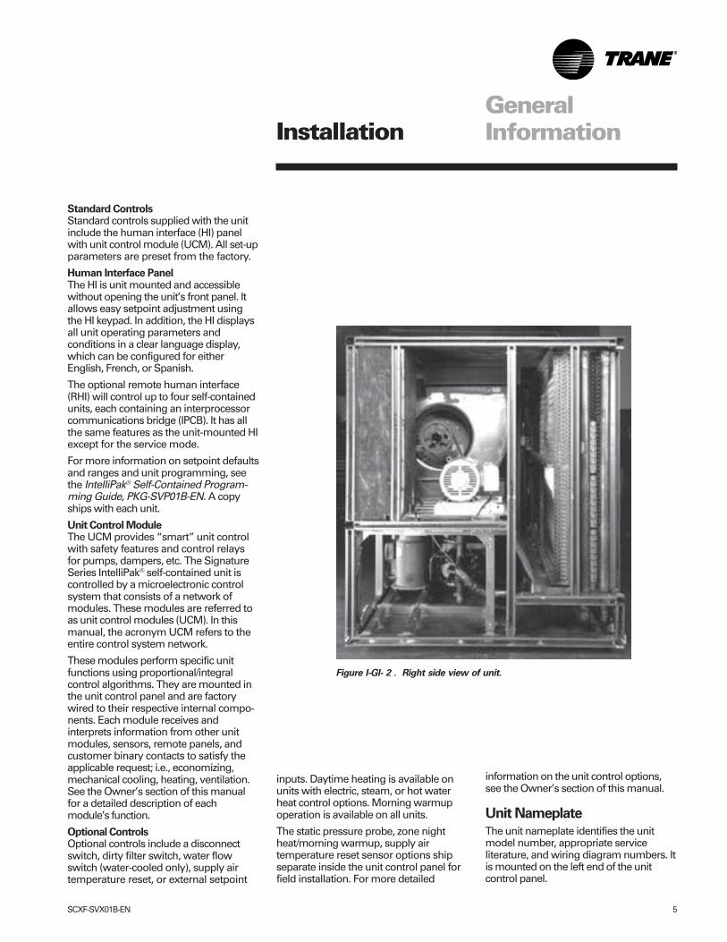
Figure I-GI- 2 . Right side view of unit.
GeneralInformation
inputs. Daytime heating is available onunits with electric, steam, or hot waterheat control options. Morning warmupoperation is available on all units.
The static pressure probe, zone nightheat/morning warmup, supply airtemperature reset sensor options shipseparate inside the unit control panel forfield installation. For more detailed
information on the unit control options,see the Owner’s section of this manual.
Unit Nameplate
The unit nameplate identifies the unitmodel number, appropriate serviceliterature, and wiring diagram numbers. Itis mounted on the left end of the unitcontrol panel.
6 SCXF-SVX01B-EN
Installation
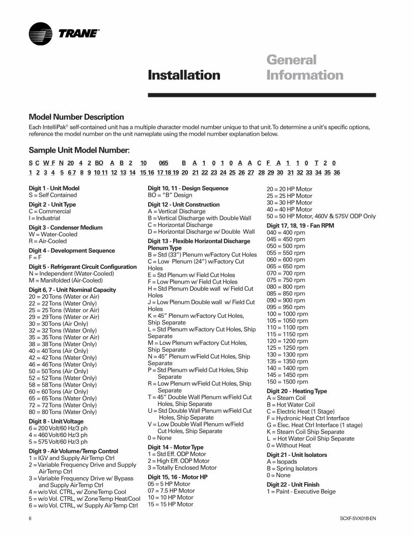
Sample Unit Model Number:
S C W F N 20 4 2 BO A B 2 10 065 B A 1 0 1 0 A A C F A 1 1 0 T 2 0
1 2 3 4 5 6 7 8 9 10 11 12 13 14 15 16 17 18 19 20 21 22 23 24 25 26 27 28 29 30 31 32 33 34 35 36
Model Number Description
Each IntelliPak® self-contained unit has a multiple character model number unique to that unit. To determine a unit’s specific options,reference the model number on the unit nameplate using the model number explanation below.
Digit 1 - Unit ModelS = Self Contained
Digit 2 - Unit TypeC = CommercialI = Industrial
Digit 3 - Condenser MediumW = Water-CooledR = Air-Cooled
Digit 4 - Development SequenceF = F
Digit 5 - Refrigerant Circuit ConfigurationN = Independent (Water-Cooled)M = Manifolded (Air-Cooled)
Digit 6, 7 - Unit Nominal Capacity20 = 20 Tons (Water or Air)22 = 22 Tons (Water Only)25 = 25 Tons (Water or Air)29 = 29 Tons (Water or Air)30 = 30 Tons (Air Only)32 = 32 Tons (Water Only)35 = 35 Tons (Water or Air)38 = 38 Tons (Water Only)40 = 40 Tons (Air Only)42 = 42 Tons (Water Only)46 = 46 Tons (Water Only)50 = 50 Tons (Air Only)52 = 52 Tons (Water Only)58 = 58 Tons (Water Only)60 = 60 Tons (Air Only)65 = 65 Tons (Water Only)72 = 72 Tons (Water Only)80 = 80 Tons (Water Only)
Digit 8 - Unit Voltage6 = 200 Volt/60 Hz/3 ph4 = 460 Volt/60 Hz/3 ph5 = 575 Volt/60 Hz/3 ph
Digit 9 - Air Volume/Temp Control1 = IGV and Supply Air Temp Ctrl2 = Variable Frequency Drive and Supply Air Temp Ctrl3 = Variable Frequency Drive w/ Bypass and Supply Air Temp Ctrl4 = w/o Vol. CTRL, w/ Zone Temp Cool5 = w/o Vol. CTRL, w/ Zone Temp Heat/Cool6 = w/o Vol. CTRL, w/ Supply Air Temp Ctrl
Digit 10, 11 - Design SequenceBO = “B” Design
Digit 12 - Unit ConstructionA = Vertical DischargeB = Vertical Discharge with Double WallC = Horizontal DischargeD = Horizontal Discharge w/ Double Wall
Digit 13 - Flexible Horizontal DischargePlenum TypeB = Std (33”) Plenum w/Factory Cut HolesC = Low Plenum (24”) w/Factory CutHolesE = Std Plenum w/ Field Cut HolesF = Low Plenum w/ Field Cut HolesH = Std Plenum Double wall w/ Field CutHolesJ = Low Plenum Double wall w/ Field CutHolesK = 45” Plenum w/Factory Cut Holes,Ship SeparateL = Std Plenum w/Factory Cut Holes, ShipSeparateM = Low Plenum w/Factory Cut Holes,Ship SeparateN = 45” Plenum w/Field Cut Holes, ShipSeparateP = Std Plenum w/Field Cut Holes, Ship SeparateR = Low Plenum w/Field Cut Holes, Ship SeparateT = 45” Double Wall Plenum w/Field Cut Holes, Ship SeparateU = Std Double Wall Plenum w/Field Cut Holes, Ship SeparateV = Low Double Wall Plenum w/Field Cut Holes, Ship Separate0 = None
Digit 14 - Motor Type1 = Std Eff. ODP Motor2 = High Eff. ODP Motor3 = Totally Enclosed Motor
Digit 15, 16 - Motor HP05 = 5 HP Motor07 = 7.5 HP Motor10 = 10 HP Motor15 = 15 HP Motor
20 = 20 HP Motor25 = 25 HP Motor30 = 30 HP Motor40 = 40 HP Motor50 = 50 HP Motor, 460V & 575V ODP Only
Digit 17, 18, 19 - Fan RPM040 = 400 rpm045 = 450 rpm050 = 500 rpm055 = 550 rpm060 = 600 rpm065 = 650 rpm070 = 700 rpm075 = 750 rpm080 = 800 rpm085 = 850 rpm090 = 900 rpm095 = 950 rpm100 = 1000 rpm105 = 1050 rpm110 = 1100 rpm115 = 1150 rpm120 = 1200 rpm125 = 1250 rpm130 = 1300 rpm135 = 1350 rpm140 = 1400 rpm145 = 1450 rpm150 = 1500 rpm
Digit 20 - Heating TypeA = Steam CoilB = Hot Water CoilC = Electric Heat (1 Stage)F = Hydronic Heat Ctrl InterfaceG = Elec. Heat Ctrl Interface (1 stage)K = Steam Coil Ship SeparateL = Hot Water Coil Ship Separate0 = Without Heat
Digit 21 - Unit IsolatorsA = IsopadsB = Spring Isolators0 = None
Digit 22 - Unit Finish1 = Paint - Executive Beige
GeneralInformation
SCXF-SVX01B-EN 7
2 = Protective Coating3 = Protective Coating w/ Finish Coat
Digit 23 - Future Use0 = None
Digit 24 - Unit Connection1 = Disconnect Switch2 = Terminal Block3 = Dual Point Power (2 Blocks)
Digit 25 - Industrial OptionsA = Protective Coated Evaporator CoilB = Silver SolderC = Stainless Steel ScrewsD = A and BE = A and CF = B and CG = A, B, and C0 = None
Digit 26 - Drain Pan TypeA = Galvanized SlopedB = Stainless Steel Sloped
Digit 27 - Waterside EconomizerA = Mechanical Clean Full Capacity (4-row)B = Mechanical Clean Low Capacity (2-row)C = Chemical Clean Full Capacity (4-row)D = Chemical Clean Low Capacity (2-row)0 = None
Digit 28 - Ventilation ControlB = Airside Econ w/ Traq™ Damper
(Top O/A)C = Airside Econ w/ Standard
Damper (Top O/A)E = Airside Econ w/ Traq™ Damper and
Comparative Enthalpy (Top O/A)F = Airside Econ w/ Standard Damperand Comparative Enthalpy (Top O/A)H = 2-Position Damper Ventilation
InterfaceJ = Airside Economizer InterfaceK = Airside Economizer Interface w/ Comparative Enthalpy
Digit 29 - Water PipingD = Left Hand Basic PipingF = Left Hand Intermediate PipingK = Left Hand Basic w/ Flow SwitchM = Left Hand Intermediate w/ Flow Switch0 = None
Digit 30 - Condenser Tube TypeA = Standard Condenser TubesB = 90/10 CuNi Condenser Tubes0 = None (Air-cooled Only)
Digit 31 - Compressor Service Valves1 = With Service Valves0 = None
Digit 32 - Miscellaneous System Control1 = Timeclock2 = Interface for Remote HI (IPCB)3 = Dirty Filter Switch4 = 1 and 25 = 1 and 36 = 2 and 37 = 1, 2 and 30 = None
Digit 33 - Control Interface OptionsA = Generic BAS Module (GBAS)B = Ventilation Override Module (VOM)C = Tracer Comm. Interface Module (TCI)D= Remote Human Interface (RHI)E= GBAS and TCIF= VOM and TCIG = GBAS and VOMH = GBAS and RHIJ = VOM and RHIK = TCI and RHIL = GBAS, VOM, and TCIM = GBAS, VOM, and RHIN = GBAS, TCI, and RHIP = VOM, TCI, and RHIR = GBAS, VOM, TCI, and RHI0 = None
Digit 34 - AgencyT = UL Agency Listing0 = None
Digit 35 - Filter Type1 = Construction Throwaway2 = Med Eff. Throwaway
Digit 36 - Miscellaneous Control OptionA = Low Entering Air Temp. Protect Device (LEATPD)B = High Duct Temp T-Stat (Ship Separate)C = Plenum High Static Switch (Ship Separate)E = A and BF = A and CH = B and CL = A, B, and C0 = None
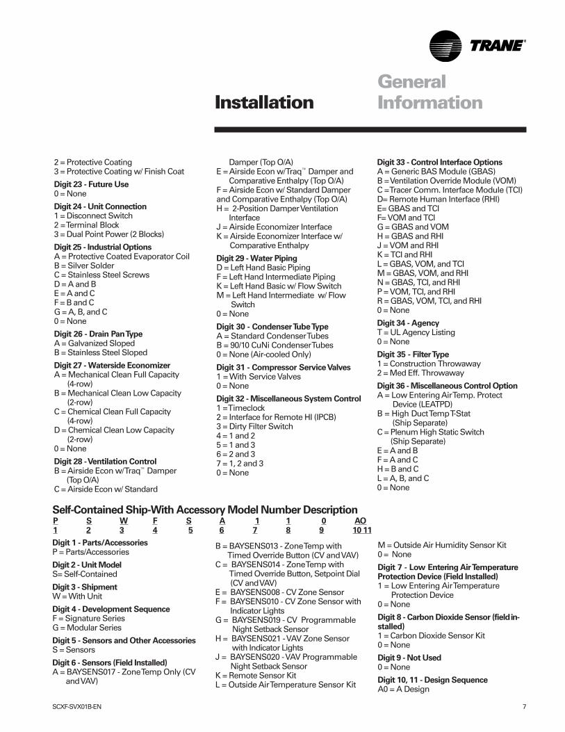
P S W F S A 1 1 0 AO1 2 3 4 5 6 7 8 9 10 11
Self-Contained Ship-With Accessory Model Number Description
Digit 1 - Parts/AccessoriesP = Parts/Accessories
Digit 2 - Unit ModelS= Self-Contained
Digit 3 - ShipmentW = With Unit
Digit 4 - Development SequenceF = Signature SeriesG = Modular Series
Digit 5 - Sensors and Other AccessoriesS = Sensors
Digit 6 - Sensors (Field Installed)A = BAYSENS017 - Zone Temp Only (CV and VAV)
B = BAYSENS013 - Zone Temp with Timed Override Button (CV and VAV)C = BAYSENS014 - Zone Temp with Timed Override Button, Setpoint Dial (CV and VAV)E = BAYSENS008 - CV Zone SensorF = BAYSENS010 - CV Zone Sensor with Indicator LightsG = BAYSENS019 - CV Programmable Night Setback SensorH = BAYSENS021 - VAV Zone Sensor with Indicator LightsJ = BAYSENS020 - VAV Programmable Night Setback SensorK = Remote Sensor KitL = Outside Air Temperature Sensor Kit
M = Outside Air Humidity Sensor Kit0 = None
Digit 7 - Low Entering Air TemperatureProtection Device (Field Installed)1 = Low Entering Air Temperature Protection Device0 = None
Digit 8 - Carbon Dioxide Sensor (fieldin-stalled)1 = Carbon Dioxide Sensor Kit0 = None
Digit 9 - Not Used0 = None
Digit 10, 11 - Design SequenceA0 = A Design
InstallationGeneralInformation
8 SCXF-SVX01B-EN
Installation
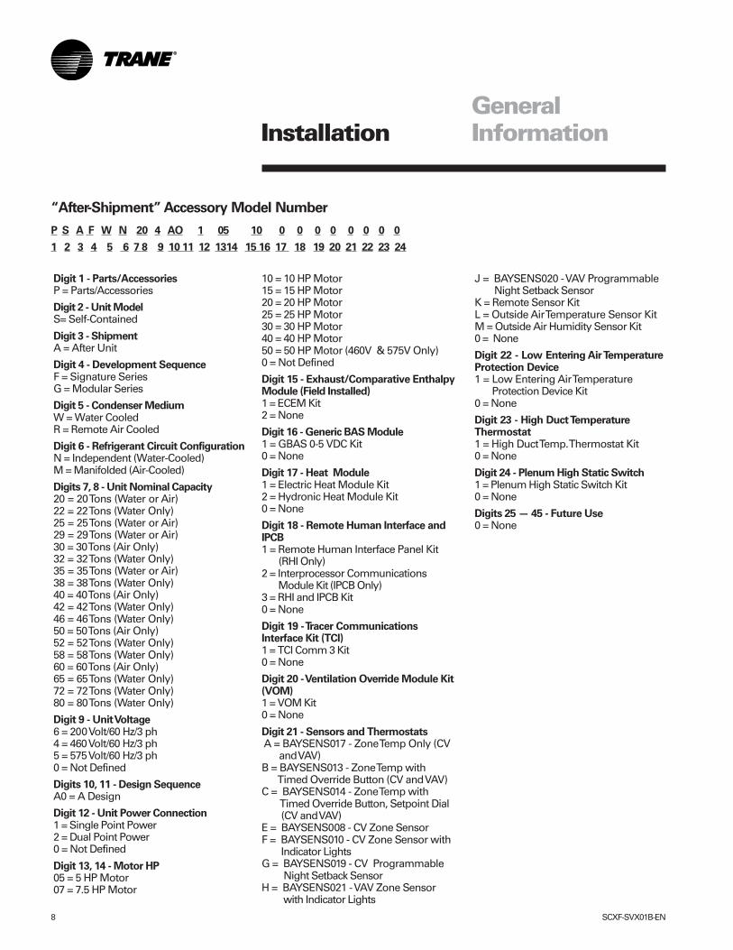
“After-Shipment” Accessory Model Number
P S A F W N 20 4 AO 1 05 10 0 0 0 0 0 0 0 0
1 2 3 4 5 6 7 8 9 10 11 12 1314 15 16 17 18 19 20 21 22 23 24
Digit 1 - Parts/AccessoriesP = Parts/Accessories
Digit 2 - Unit ModelS= Self-Contained
Digit 3 - ShipmentA = After Unit
Digit 4 - Development SequenceF = Signature SeriesG = Modular Series
Digit 5 - Condenser MediumW = Water CooledR = Remote Air Cooled
Digit 6 - Refrigerant Circuit ConfigurationN = Independent (Water-Cooled)M = Manifolded (Air-Cooled)
Digits 7, 8 - Unit Nominal Capacity20 = 20 Tons (Water or Air)22 = 22 Tons (Water Only)25 = 25 Tons (Water or Air)29 = 29 Tons (Water or Air)30 = 30 Tons (Air Only)32 = 32 Tons (Water Only)35 = 35 Tons (Water or Air)38 = 38 Tons (Water Only)40 = 40 Tons (Air Only)42 = 42 Tons (Water Only)46 = 46 Tons (Water Only)50 = 50 Tons (Air Only)52 = 52 Tons (Water Only)58 = 58 Tons (Water Only)60 = 60 Tons (Air Only)65 = 65 Tons (Water Only)72 = 72 Tons (Water Only)80 = 80 Tons (Water Only)
Digit 9 - Unit Voltage6 = 200 Volt/60 Hz/3 ph4 = 460 Volt/60 Hz/3 ph5 = 575 Volt/60 Hz/3 ph0 = Not Defined
Digits 10, 11 - Design SequenceA0 = A Design
Digit 12 - Unit Power Connection1 = Single Point Power2 = Dual Point Power0 = Not Defined
Digit 13, 14 - Motor HP05 = 5 HP Motor07 = 7.5 HP Motor
10 = 10 HP Motor15 = 15 HP Motor20 = 20 HP Motor25 = 25 HP Motor30 = 30 HP Motor40 = 40 HP Motor50 = 50 HP Motor (460V & 575V Only)0 = Not Defined
Digit 15 - Exhaust/Comparative EnthalpyModule (Field Installed)1 = ECEM Kit2 = None
Digit 16 - Generic BAS Module1 = GBAS 0-5 VDC Kit0 = None
Digit 17 - Heat Module1 = Electric Heat Module Kit2 = Hydronic Heat Module Kit0 = None
Digit 18 - Remote Human Interface andIPCB1 = Remote Human Interface Panel Kit (RHI Only)2 = Interprocessor Communications Module Kit (IPCB Only)3 = RHI and IPCB Kit0 = None
Digit 19 - Tracer CommunicationsInterface Kit (TCI)1 = TCI Comm 3 Kit0 = None
Digit 20 - Ventilation Override Module Kit(VOM)1 = VOM Kit0 = None
Digit 21 - Sensors and Thermostats A = BAYSENS017 - Zone Temp Only (CV and VAV)B = BAYSENS013 - Zone Temp with Timed Override Button (CV and VAV)C = BAYSENS014 - Zone Temp with Timed Override Button, Setpoint Dial (CV and VAV)E = BAYSENS008 - CV Zone SensorF = BAYSENS010 - CV Zone Sensor with Indicator LightsG = BAYSENS019 - CV Programmable Night Setback SensorH = BAYSENS021 - VAV Zone Sensor with Indicator Lights
J = BAYSENS020 - VAV Programmable Night Setback SensorK = Remote Sensor KitL = Outside Air Temperature Sensor KitM = Outside Air Humidity Sensor Kit0 = None
Digit 22 - Low Entering Air TemperatureProtection Device1 = Low Entering Air Temperature Protection Device Kit0 = None
Digit 23 - High Duct TemperatureThermostat1 = High Duct Temp. Thermostat Kit0 = None
Digit 24 - Plenum High Static Switch1 = Plenum High Static Switch Kit0 = None
Digits 25 — 45 - Future Use0 = None
GeneralInformation
SCXF-SVX01B-EN 9
Installation
Receiving and Handling
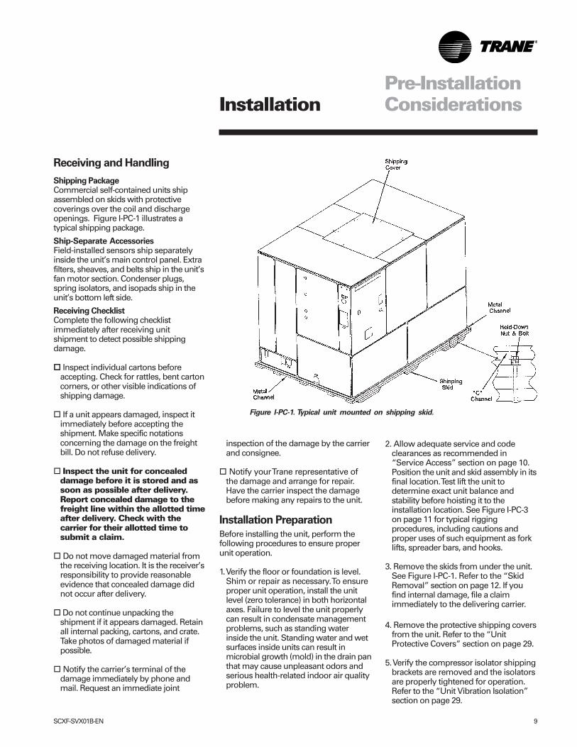
Shipping PackageCommercial self-contained units shipassembled on skids with protectivecoverings over the coil and dischargeopenings. Figure I-PC-1 illustrates atypical shipping package.
Ship-Separate AccessoriesField-installed sensors ship separatelyinside the unit’s main control panel. Extrafilters, sheaves, and belts ship in the unit’sfan motor section. Condenser plugs,spring isolators, and isopads ship in theunit’s bottom left side.
Receiving ChecklistComplete the following checklistimmediately after receiving unitshipment to detect possible shippingdamage.
�� Inspect individual cartons beforeaccepting. Check for rattles, bent cartoncorners, or other visible indications ofshipping damage.
� If a unit appears damaged, inspect itimmediately before accepting theshipment. Make specific notationsconcerning the damage on the freightbill. Do not refuse delivery.
� Inspect the unit for concealeddamage before it is stored and assoon as possible after delivery.Report concealed damage to thefreight line within the allotted timeafter delivery. Check with thecarrier for their allotted time tosubmit a claim.
� Do not move damaged material fromthe receiving location. It is the receiver’sresponsibility to provide reasonableevidence that concealed damage didnot occur after delivery.
� Do not continue unpacking theshipment if it appears damaged. Retainall internal packing, cartons, and crate.Take photos of damaged material ifpossible.
� Notify the carrier’s terminal of thedamage immediately by phone andmail. Request an immediate joint
Figure I-PC-1. Typical unit mounted on shipping skid.
inspection of the damage by the carrierand consignee.
� Notify your Trane representative ofthe damage and arrange for repair.Have the carrier inspect the damagebefore making any repairs to the unit.
Installation Preparation
Before installing the unit, perform thefollowing procedures to ensure properunit operation.
1. Verify the floor or foundation is level.Shim or repair as necessary. To ensureproper unit operation, install the unitlevel (zero tolerance) in both horizontalaxes. Failure to level the unit properlycan result in condensate managementproblems, such as standing waterinside the unit. Standing water and wetsurfaces inside units can result inmicrobial growth (mold) in the drain panthat may cause unpleasant odors andserious health-related indoor air qualityproblem.
2. Allow adequate service and codeclearances as recommended in“Service Access” section on page 10.Position the unit and skid assembly in itsfinal location. Test lift the unit todetermine exact unit balance andstability before hoisting it to theinstallation location. See Figure I-PC-3on page 11 for typical riggingprocedures, including cautions andproper uses of such equipment as forklifts, spreader bars, and hooks.
3. Remove the skids from under the unit.See Figure I-PC-1. Refer to the “SkidRemoval” section on page 12. If youfind internal damage, file a claimimmediately to the delivering carrier.
4. Remove the protective shipping coversfrom the unit. Refer to the “UnitProtective Covers” section on page 29.
5. Verify the compressor isolator shippingbrackets are removed and the isolatorsare properly tightened for operation.Refer to the “Unit Vibration Isolation”section on page 29.
Pre-InstallationConsiderations
10 SCXF-SVX01B-EN
The compressor, condenser, and fanmotor access panels are secured withquick acting fasteners. Fast threadscrews secure access panels foreconomizer coils, evaporator coilsexpansion valves, water valves, and leftfan bearing. Access to other componentsrequires removal of semipermanentpanels secured with sheet metal screws.During operation, sight glasses areviewable through the portholes on theunit’s left upper panel.
Disconnect electrical powersource before servicing the unit.Failure to do so may result ininjury or death from electricalshock or entanglement in movingparts.
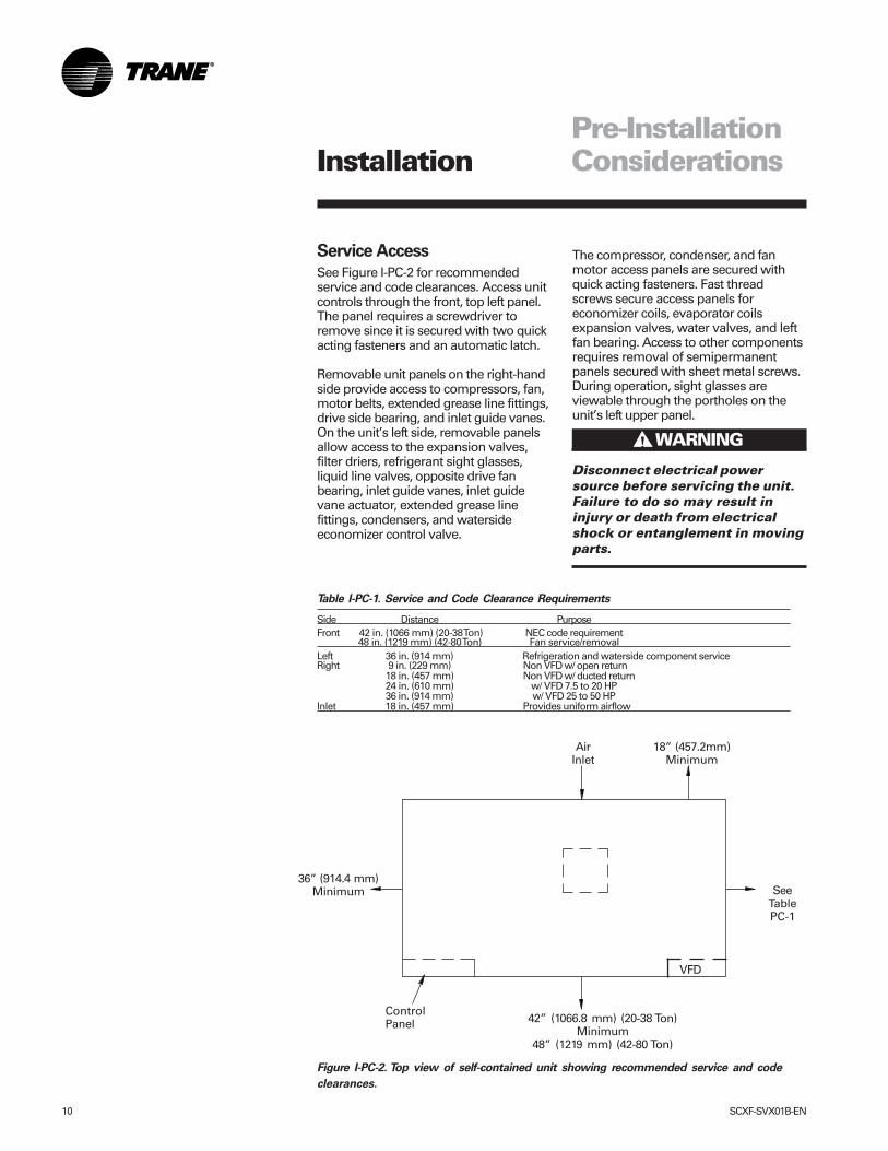
Table I-PC-1. Service and Code Clearance Requirements
Side Distance PurposeFront 42 in. (1066 mm) (20-38 Ton) NEC code requirement
48 in. (1219 mm) (42-80 Ton) Fan service/removalLeft 36 in. (914 mm) Refrigeration and waterside component serviceRight 9 in. (229 mm) Non VFD w/ open return
18 in. (457 mm) Non VFD w/ ducted return24 in. (610 mm) w/ VFD 7.5 to 20 HP36 in. (914 mm) w/ VFD 25 to 50 HP
Inlet 18 in. (457 mm) Provides uniform airflow
Service Access
See Figure I-PC-2 for recommendedservice and code clearances. Access unitcontrols through the front, top left panel.The panel requires a screwdriver toremove since it is secured with two quickacting fasteners and an automatic latch.
Removable unit panels on the right-handside provide access to compressors, fan,motor belts, extended grease line fittings,drive side bearing, and inlet guide vanes.On the unit’s left side, removable panelsallow access to the expansion valves,filter driers, refrigerant sight glasses,liquid line valves, opposite drive fanbearing, inlet guide vanes, inlet guidevane actuator, extended grease linefittings, condensers, and watersideeconomizer control valve.
����� WARNING!
Figure I-PC-2. Top view of self-contained unit showing recommended service and code
clearances.
AirInlet
18” (457.2mm)Minimum
SeeTablePC-1
ControlPanel 42” (1066.8 mm) (20-38 Ton)
Minimum48” (1219 mm) (42-80 Ton)
Pre-InstallationConsiderations
36” (914.4 mm)Minimum
Installation
VFD
SCXF-SVX01B-EN 11
Pre-InstallationConsiderations
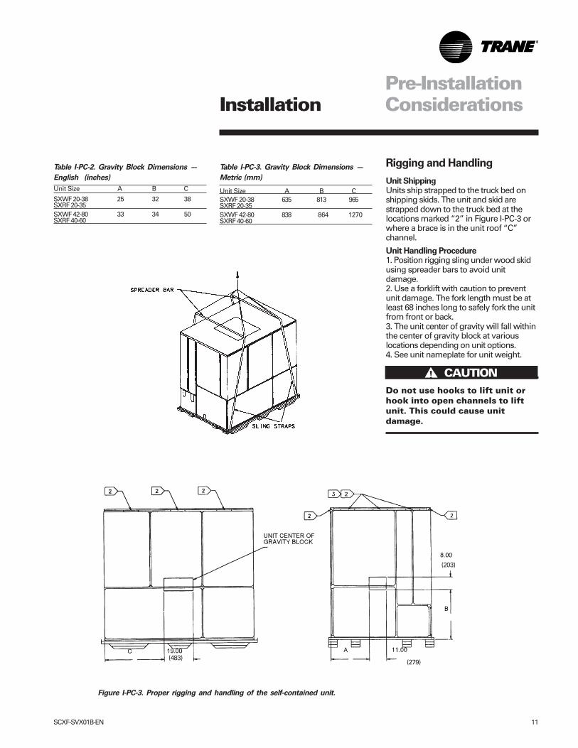
Figure I-PC-3. Proper rigging and handling of the self-contained unit.
Table I-PC-2. Gravity Block Dimensions —
English (inches)
Unit Size A B C
SXWF 20-38 25 32 38SXRF 20-35SXWF 42-80 33 34 50SXRF 40-60
Rigging and Handling
Unit ShippingUnits ship strapped to the truck bed onshipping skids. The unit and skid arestrapped down to the truck bed at thelocations marked “2” in Figure I-PC-3 orwhere a brace is in the unit roof “C”channel.
Unit Handling Procedure1. Position rigging sling under wood skidusing spreader bars to avoid unitdamage.2. Use a forklift with caution to preventunit damage. The fork length must be atleast 68 inches long to safely fork the unitfrom front or back.3. The unit center of gravity will fall withinthe center of gravity block at variouslocations depending on unit options.4. See unit nameplate for unit weight.
Do not use hooks to lift unit orhook into open channels to liftunit. This could cause unitdamage.
(483)(279)
(203)
Table I-PC-3. Gravity Block Dimensions —
Metric (mm)
Unit Size A B CSXWF 20-38 635 813 965SXRF 20-35SXWF 42-80 838 864 1270SXRF 40-60
Installation
����� CAUTION!
12 SCXF-SVX01B-EN
Pre-InstallationConsiderations
Skid Removal
The unit ships on skids to provide forkliftlocations from the front or rear. The skidallows easy maneuverability of the unitduring storage and transportation.Remove the skids before placing the unitin its permanent location.
Remove the skids using a forklift or jack.Lift one end of the unit off of the skids.See Figure I-PC-3 on page 11. Slide theskids out and lower the unit at theinstallation location. If using vibrationisolators for external isolation, refer to the“Vibration Isolator Unit Option” sectionon page 29.
Note: External isolation is not necessarysince units are internally isolated. Consult avibration specialist before externallyisolating the unit.
Pre-Installation Checklist
Complete the following checklist beforebeginning unit installation.
� Verify the unit size and tagging with theunit nameplate.
� Make certain the floor or foundation islevel, solid, and sufficient to support theunit and accessory weights. See TableI-DW-1 on page 13. Level or repair thefloor before positioning the unit ifneccesary.
� Allow minimum recommendedclearances for routine maintenance andservice. Refer to unit submittals fordimensions.
� Allow three fan diameters above theunit for the discharge ductwork. Returnair enters the rear of the unit andconditioned supply air dischargesthrough the top.
� Electrical connection knockouts are onthe top, left side of the unit.
� Allow adequate space for pipingaccess and panel removal. Condenserwater piping, refrigerant piping, andcondensate drain connections are onthe lower left end panel.
Note: Unit height and connection locationswill change if using vibration isolators. Theunit height may increase up to 5 7/8” withspring type isolators.
� Electrical supply power must meetspecific balance and voltagerequirements as described in the“Electrical Requirements” section onpage 26.
� Water-cooled units only: The installeris responsible for providing a condensermain, standby water pump, coolingtower, pressure gauges, strainers, andall components for waterside piping.See the “Water Piping” section on page23 for general watersiderecommendations.
� Air-cooled units only: The installer isresponsible for providing and installingthe remote air-cooled condenser andrefrigerant piping, including filter driers.
Installation
SCXF-SVX01B-EN 13
Dimensionsand Weights
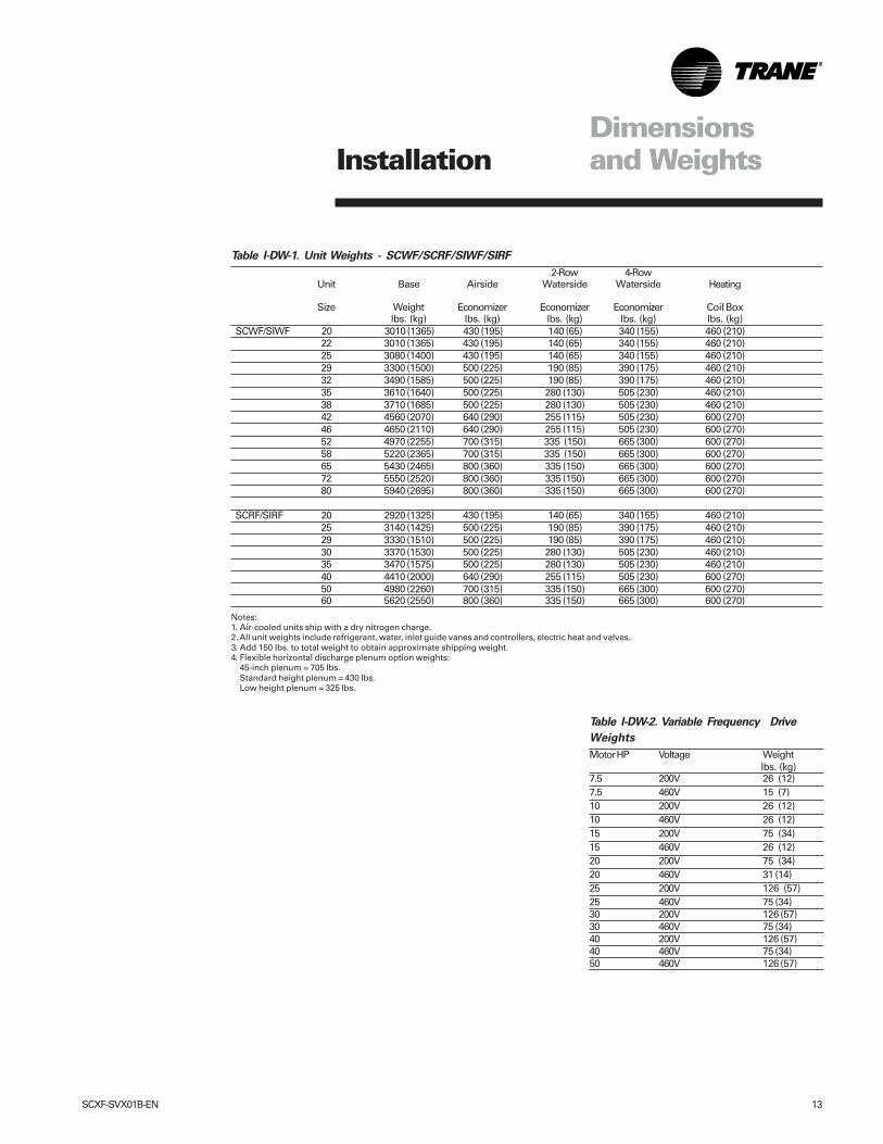
Table I-DW-1. Unit Weights - SCWF/SCRF/SIWF/SIRF
2-Row 4-RowUnit Base Airside Waterside Waterside Heating
Size Weight Economizer Economizer Economizer Coil Boxlbs. (kg) lbs. (kg) lbs. (kg) lbs. (kg) lbs. (kg)
SCWF/SIWF 20 3010 (1365) 430 (195) 140 (65) 340 (155) 460 (210)22 3010 (1365) 430 (195) 140 (65) 340 (155) 460 (210)25 3080 (1400) 430 (195) 140 (65) 340 (155) 460 (210)29 3300 (1500) 500 (225) 190 (85) 390 (175) 460 (210)32 3490 (1585) 500 (225) 190 (85) 390 (175) 460 (210)35 3610 (1640) 500 (225) 280 (130) 505 (230) 460 (210)38 3710 (1685) 500 (225) 280 (130) 505 (230) 460 (210)42 4560 (2070) 640 (290) 255 (115) 505 (230) 600 (270)46 4650 (2110) 640 (290) 255 (115) 505 (230) 600 (270)52 4970 (2255) 700 (315) 335 (150) 665 (300) 600 (270)58 5220 (2365) 700 (315) 335 (150) 665 (300) 600 (270)65 5430 (2465) 800 (360) 335 (150) 665 (300) 600 (270)72 5550 (2520) 800 (360) 335 (150) 665 (300) 600 (270)80 5940 (2695) 800 (360) 335 (150) 665 (300) 600 (270)
SCRF/SIRF 20 2920 (1325) 430 (195) 140 (65) 340 (155) 460 (210)25 3140 (1425) 500 (225) 190 (85) 390 (175) 460 (210)29 3330 (1510) 500 (225) 190 (85) 390 (175) 460 (210)30 3370 (1530) 500 (225) 280 (130) 505 (230) 460 (210)35 3470 (1575) 500 (225) 280 (130) 505 (230) 460 (210)40 4410 (2000) 640 (290) 255 (115) 505 (230) 600 (270)50 4980 (2260) 700 (315) 335 (150) 665 (300) 600 (270)60 5620 (2550) 800 (360) 335 (150) 665 (300) 600 (270)
Notes:1. Air-cooled units ship with a dry nitrogen charge.2. All unit weights include refrigerant, water, inlet guide vanes and controllers, electric heat and valves.3. Add 150 lbs. to total weight to obtain approximate shipping weight.4. Flexible horizontal discharge plenum option weights:
45-inch plenum = 705 lbs.Standard height plenum = 430 lbs.Low height plenum = 325 lbs.
Installation
Table I-DW-2. Variable Frequency Drive
Weights
Motor HP Voltage Weight lbs. (kg)
7.5 200V 26 (12)7.5 460V 15 (7)10 200V 26 (12)10 460V 26 (12)15 200V 75 (34)15 460V 26 (12)20 200V 75 (34)20 460V 31 (14)25 200V 126 (57)25 460V 75 (34)30 200V 126 (57)30 460V 75 (34)40 200V 126 (57)40 460V 75 (34)50 460V 126 (57)
14 SCXF-SVX01B-EN
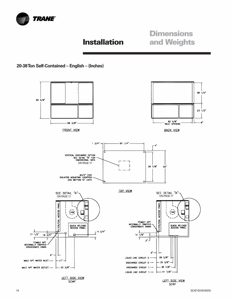
Dimensionsand Weights
20-38 Ton Self-Contained – English – (Inches)
ON PAGE 17ON PAGE 17
ON PAGE 17
Installation
SCXF-SVX01B-EN 15
ON PAGE 17ON PAGE 17
ON PAGE 17
Dimensionsand WeightsInstallation
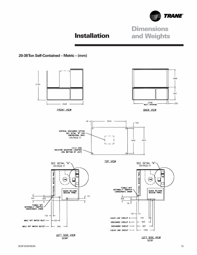
20-38 Ton Self-Contained – Metric – (mm)
16 SCXF-SVX01B-EN
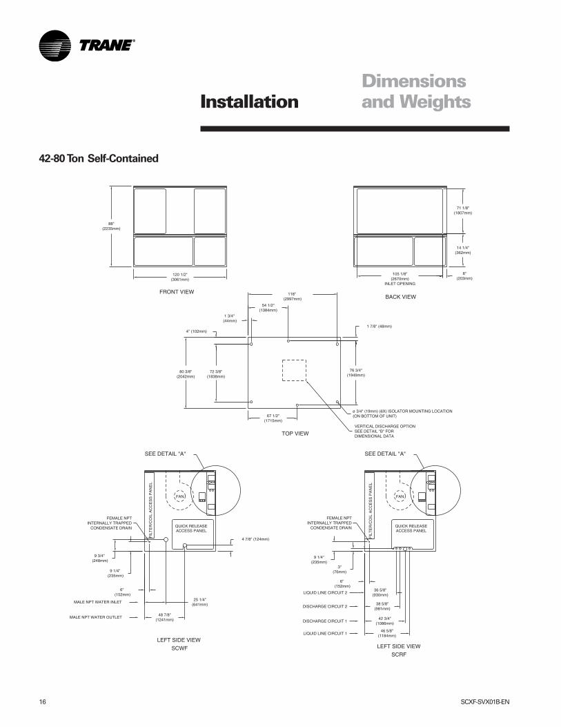
42-80 Ton Self-Contained
Dimensionsand WeightsInstallation
SCXF-SVX01B-EN 17
Dimensionsand WeightsInstallation
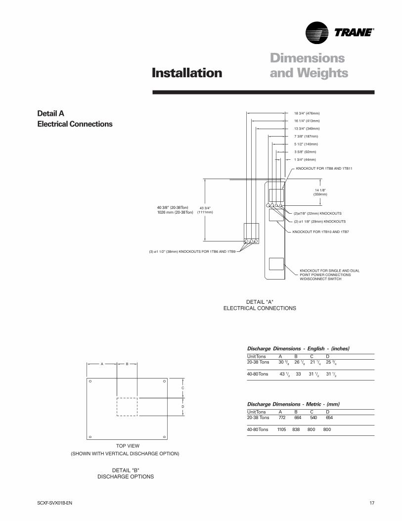
Detail A
Electrical Connections
Discharge Dimensions - English - (inches)
Unit Tons A B C D20-38 Tons 30 3/8 26 1/8 21 1/4 25 3/4
40-80 Tons 43 1/2 33 31 1/2 31 1/2
Discharge Dimensions - Metric - (mm)
Unit Tons A B C D20-38 Tons 772 664 540 654
40-80 Tons 1105 838 800 800
40 3/8” (20-38 Ton)1026 mm (20-38 Ton)
18 SCXF-SVX01B-EN
Dimensionsand Weights
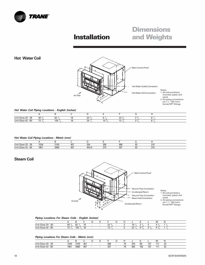
Hot Water Coil Piping Locations - English (inches)
A B C D E F G H
Unit Sizes 20 - 38 60 3/8 82 7/8 18 20 5/8 8 1/8 22 3/8 3 5/8 8 1/4Unit Sizes 42 - 80 72 7/8 105 1/4 18 24 1/2 10 3/4 13 1/4 3 5/8 8 1/4
Hot Water Coil Piping Locations - Metric (mm)
A B C D E F G HUnit Sizes 20 - 38 1534 2105 457 524 206 568 92 210Unit Sizes 42 - 80 1851 2680 457 404.9 273 337 92 210
Piping Locations For Steam Coils - English (inches)
A B C D E F G H J K L M NUnit Sizes 20 - 38 60 3/8 82 7/8 18 - - 22 3/8 - 3 18 1/2 3 7/8 5 4 3/8 1 1/4Unit Sizes 42 - 80 72 7/8 105 1/4 18 - - 13 1/4 - 3 22 1/8 6 3/8 5 3/8 4 3/8 1 1/4
Piping Locations For Steam Coils - Metric (mm)
A B C D E F G H J K L M NUnit Sizes 20 - 38 1534 2105 457 - - 568 - 76 470 98 127 111 32Unit Sizes 42 - 80 1851 2680 457 - - 337 - 76 562 162 137 111 32
Notes:1. All coils are factory
mounted, piped, andwired.
2. All piping connectionsare 1-1/2” (38.1mm)female NPT fittings.
Hot Water Coil
Notes:1. All coils are factory
mounted, piped, andwired.
2. All piping connectionsare 1-1/2” (38.1mm)female NPT fittings.
Steam Coil
Main Control Panel
Main Control Panel
Air Inlet
Hot Water Outlet Connection
Hot Water Inlet Connection
HF
G
A
B
E
D
C
Air Inlet
C
A
M
F
H
J
KL
B
Condensate Return
Steam Inlet ConnectionVacuum Trap Connection
Condensate Return
Vacuum Trap Connection
N
Installation
SCXF-SVX01B-EN 19
Dimensionsand Weights
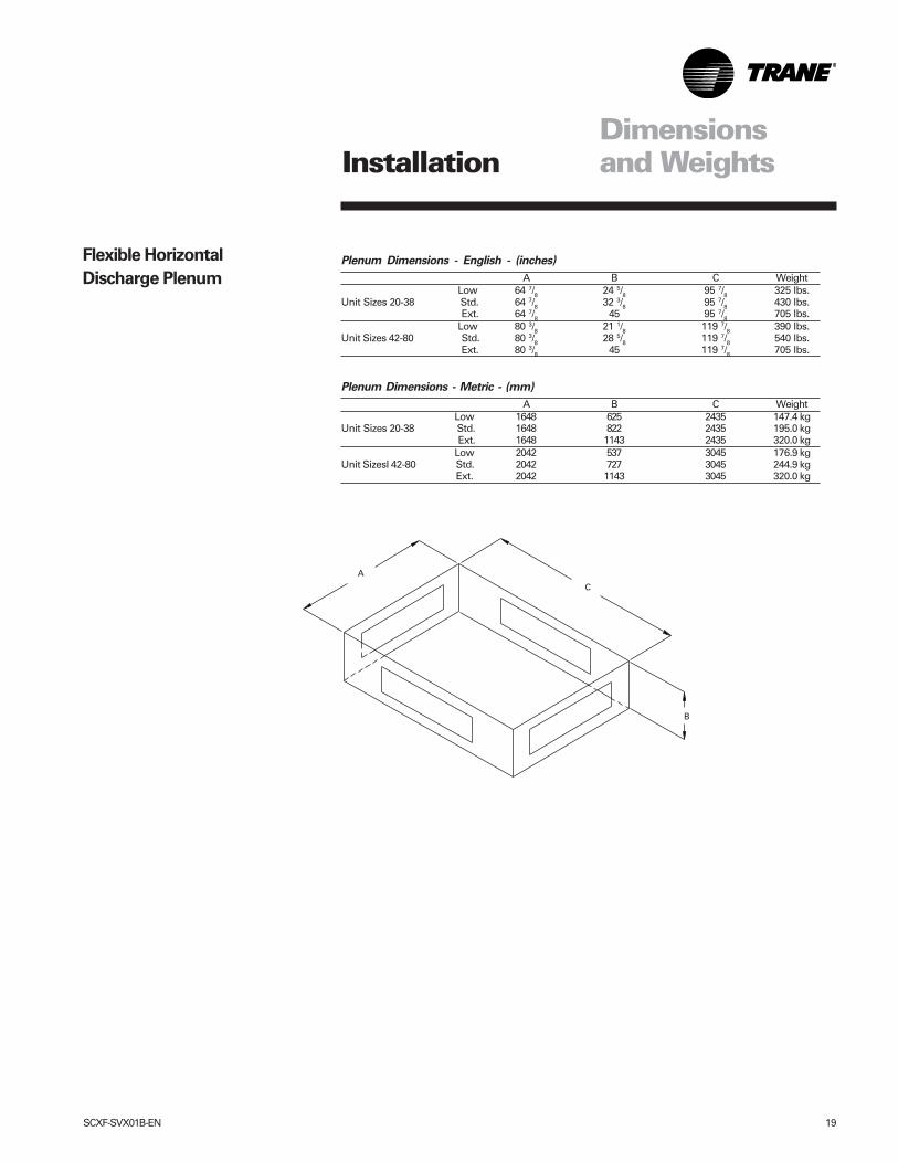
Plenum Dimensions - English - (inches)
A B C Weight Low 64 7/8 24 5/8 95 7/8 325 lbs.
Unit Sizes 20-38 Std. 64 7/8 32 3/8 95 7/8 430 lbs. Ext. 64 7/8 45 95 7/8 705 lbs. Low 80 3/8 21 1/8 119 7/8 390 lbs.
Unit Sizes 42-80 Std. 80 3/8 28 5/8 119 7/8 540 lbs. Ext. 80 3/8 45 119 7/8 705 lbs.
Plenum Dimensions - Metric - (mm)
A B C Weight Low 1648 625 2435 147.4 kg
Unit Sizes 20-38 Std. 1648 822 2435 195.0 kg Ext. 1648 1143 2435 320.0 kg Low 2042 537 3045 176.9 kg
Unit SizesI 42-80 Std. 2042 727 3045 244.9 kg Ext. 2042 1143 3045 320.0 kg
B
C
A
Flexible Horizontal
Discharge Plenum
Installation
20 SCXF-SVX01B-EN
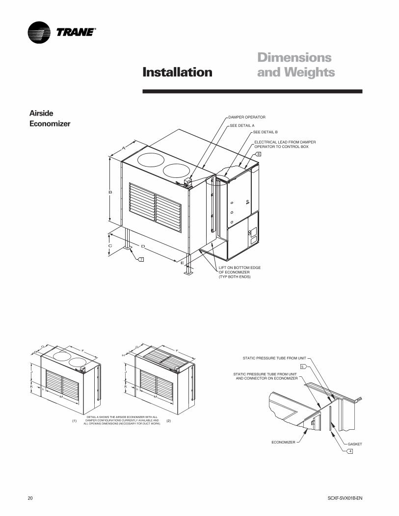
Airside
Economizer
Dimensionsand WeightsInstallation
SCXF-SVX01B-EN 21
Dimensionsand Weights
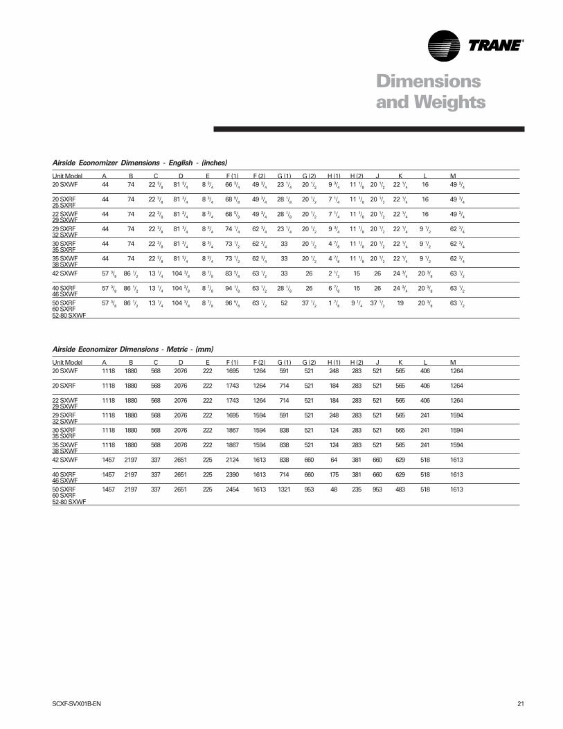
Airside Economizer Dimensions - English - (inches)
Unit Model A B C D E F (1) F (2) G (1) G (2) H (1) H (2) J K L M20 SXWF 44 74 22 3/8 81 3/4 8 3/4 66 3/4 49 3/4 23 1/4 20 1/2 9 3/4 11 1/8 20 1/2 22 1/4 16 49 3/4
20 SXRF 44 74 22 3/8 81 3/4 8 3/4 68 5/8 49 3/4 28 1/8 20 1/2 7 1/4 11 1/8 20 1/2 22 1/4 16 49 3/425 SXRF22 SXWF 44 74 22 3/8 81 3/4 8 3/4 68 5/8 49 3/4 28 1/8 20 1/2 7 1/4 11 1/8 20 1/2 22 1/4 16 49 3/429 SXWF29 SXRF 44 74 22 3/8 81 3/4 8 3/4 74 1/4 62 3/4 23 1/4 20 1/2 9 3/4 11 1/8 20 1/2 22 1/4 9 1/2 62 3/432 SXWF30 SXRF 44 74 22 3/8 81 3/4 8 3/4 73 1/2 62 3/4 33 20 1/2 4 7/8 11 1/8 20 1/2 22 1/4 9 1/2 62 3/435 SXRF35 SXWF 44 74 22 3/8 81 3/4 8 3/4 73 1/2 62 3/4 33 20 1/2 4 7/8 11 1/8 20 1/2 22 1/4 9 1/2 62 3/438 SXWF42 SXWF 57 3/8 86 1/2 13 1/4 104 3/8 8 7/8 83 5/8 63 1/2 33 26 2 1/2 15 26 24 3/4 20 3/8 63 1/2
40 SXRF 57 3/8 86 1/2 13 1/4 104 3/8 8 7/8 94 1/8 63 1/2 28 1/8 26 6 7/8 15 26 24 3/4 20 3/8 63 1/246 SXWF50 SXRF 57 3/8 86 1/2 13 1/4 104 3/8 8 7/8 96 5/8 63 1/2 52 37 1/2 1 7/8 9 1/4 37 1/2 19 20 3/8 63 1/260 SXRF52-80 SXWF
Airside Economizer Dimensions - Metric - (mm)
Unit Model A B C D E F (1) F (2) G (1) G (2) H (1) H (2) J K L M20 SXWF 1118 1880 568 2076 222 1695 1264 591 521 248 283 521 565 406 1264
20 SXRF 1118 1880 568 2076 222 1743 1264 714 521 184 283 521 565 406 1264
22 SXWF 1118 1880 568 2076 222 1743 1264 714 521 184 283 521 565 406 126429 SXWF29 SXRF 1118 1880 568 2076 222 1695 1594 591 521 248 283 521 565 241 159432 SXWF30 SXRF 1118 1880 568 2076 222 1867 1594 838 521 124 283 521 565 241 159435 SXRF35 SXWF 1118 1880 568 2076 222 1867 1594 838 521 124 283 521 565 241 159438 SXWF42 SXWF 1457 2197 337 2651 225 2124 1613 838 660 64 381 660 629 518 1613
40 SXRF 1457 2197 337 2651 225 2390 1613 714 660 175 381 660 629 518 161346 SXWF50 SXRF 1457 2197 337 2651 225 2454 1613 1321 953 48 235 953 483 518 161360 SXRF52-80 SXWF
22 SCXF-SVX01B-EN
MechanicalRequirements
Duct Connections
Disconnect electrical powersource before servicing the unit.Failure to do so may result ininjury or death from electricalshock or entanglement in movingparts.
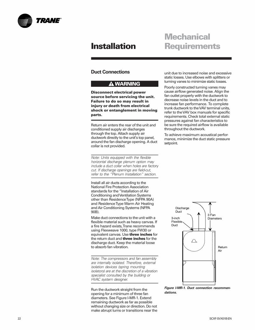
Return air enters the rear of the unit andconditioned supply air dischargesthrough the top. Attach supply airductwork directly to the unit’s top panel,around the fan discharge opening. A ductcollar is not provided.
Note: Units equipped with the flexiblehorizontal discharge plenum option mayinclude a duct collar when holes are factorycut. If discharge openings are field-cut,refer to the “Plenum Installation” section.
Install all air ducts according to theNational Fire Protection Associationstandards for the “Installation of AirConditioning and Ventilation Systemsother than Residence Type (NFPA 90A)and Residence Type Warm Air Heatingand Air Conditioning Systems (NFPA90B).
Make duct connections to the unit with aflexible material such as heavy canvas. Ifa fire hazard exists, Trane recommendsusing Flexweave 1000, type FW30 orequivalent canvas. Use three inches forthe return duct and three inches for thedischarge duct. Keep the material looseto absorb fan vibration.
Note: The compressors and fan assemblyare internally isolated. Therefore, externalisolation devices (spring mountingisolators) are at the discretion of a vibrationspecialist consulted by the building orHVAC system designer.
Run the ductwork straight from theopening for a minimum of three fandiameters. See Figure I-MR-1. Extendremaining ductwork as far as possiblewithout changing size or direction. Do notmake abrupt turns or transitions near the
unit due to increased noise and excessivestatic losses. Use elbows with splitters orturning vanes to minimize static losses.
Poorly constructed turning vanes maycause airflow generated noise. Align thefan outlet properly with the ductwork todecrease noise levels in the duct and toincrease fan performance. To completetrunk ductwork to the VAV terminal units,refer to the VAV box manuals for specificrequirements. Check total external staticpressures against fan characteristics tobe sure the required airflow is availablethroughout the ductwork.
To achieve maximum acoustical perfor-mance, minimize the duct static pressuresetpoint.
Figure I-MR-1. Duct connection recommen-
dations.
3 FanDiameters
DischargeDuct
3-inchFlexibleDuct
ReturnAir
����� WARNING!
Installation
SCXF-SVX01B-EN 23
MechanicalRequirements
Water Piping
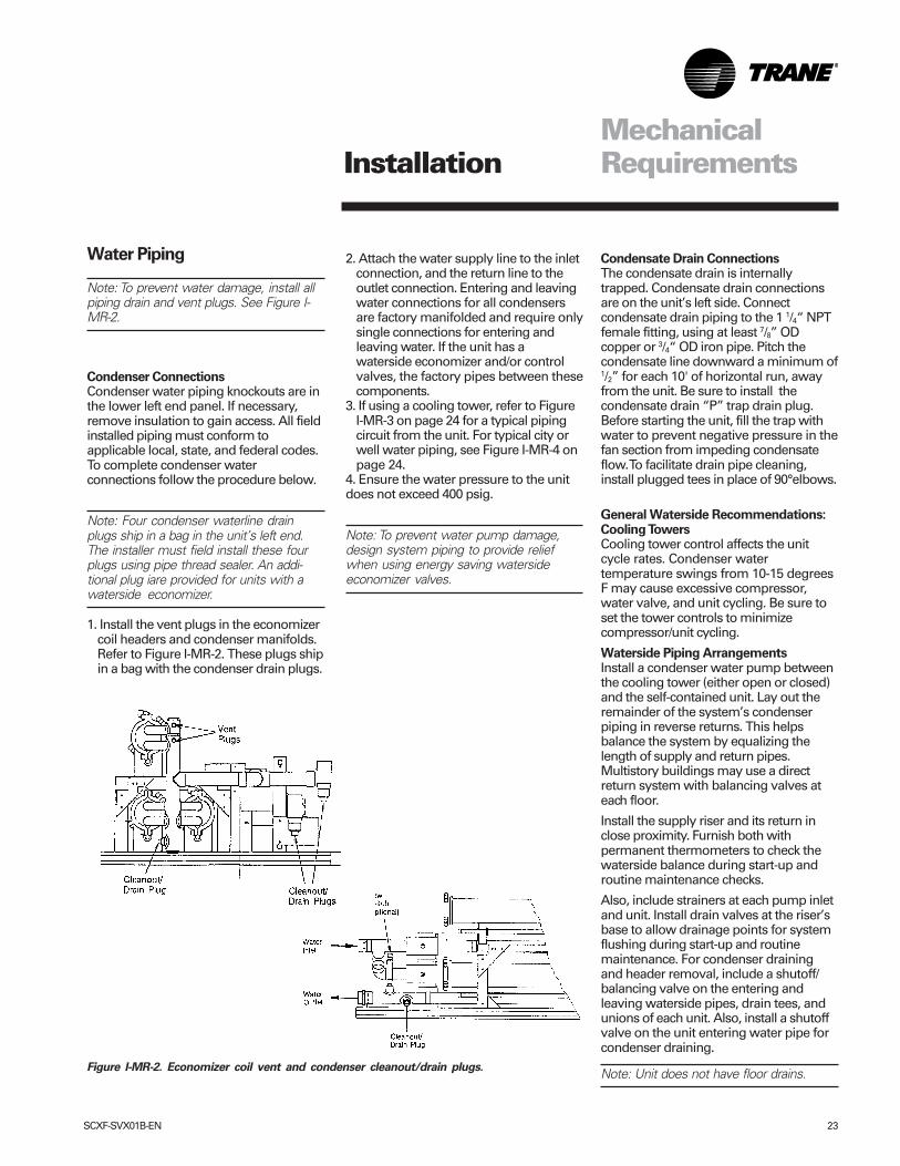
Note: To prevent water damage, install allpiping drain and vent plugs. See Figure I-MR-2.
Condenser ConnectionsCondenser water piping knockouts are inthe lower left end panel. If necessary,remove insulation to gain access. All fieldinstalled piping must conform toapplicable local, state, and federal codes.To complete condenser waterconnections follow the procedure below.
Note: Four condenser waterline drainplugs ship in a bag in the unit’s left end.The installer must field install these fourplugs using pipe thread sealer. An addi-tional plug iare provided for units with awaterside economizer.
1. Install the vent plugs in the economizercoil headers and condenser manifolds.Refer to Figure I-MR-2. These plugs shipin a bag with the condenser drain plugs.
2. Attach the water supply line to the inletconnection, and the return line to theoutlet connection. Entering and leavingwater connections for all condensersare factory manifolded and require onlysingle connections for entering andleaving water. If the unit has awaterside economizer and/or controlvalves, the factory pipes between thesecomponents.
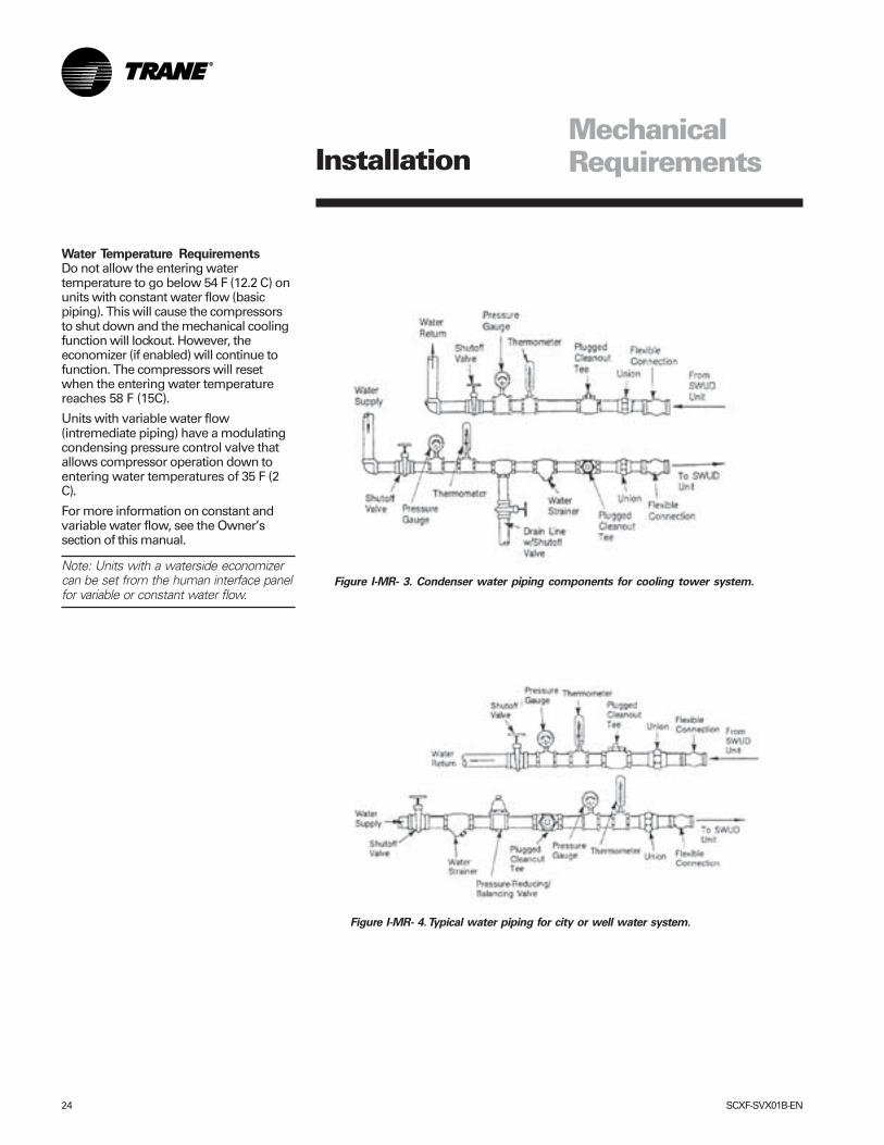
3. If using a cooling tower, refer to FigureI-MR-3 on page 24 for a typical pipingcircuit from the unit. For typical city orwell water piping, see Figure I-MR-4 onpage 24.
4. Ensure the water pressure to the unitdoes not exceed 400 psig.
Note: To prevent water pump damage,design system piping to provide reliefwhen using energy saving watersideeconomizer valves.
Figure I-MR-2. Economizer coil vent and condenser cleanout/drain plugs.
Installation
Condensate Drain ConnectionsThe condensate drain is internallytrapped. Condensate drain connectionsare on the unit’s left side. Connectcondensate drain piping to the 1 1/4“ NPTfemale fitting, using at least 7/8” ODcopper or 3/4“ OD iron pipe. Pitch thecondensate line downward a minimum of1/2” for each 10' of horizontal run, awayfrom the unit. Be sure to install thecondensate drain “P” trap drain plug.Before starting the unit, fill the trap withwater to prevent negative pressure in thefan section from impeding condensateflow. To facilitate drain pipe cleaning,install plugged tees in place of 90°elbows.
General Waterside Recommendations:Cooling TowersCooling tower control affects the unitcycle rates. Condenser watertemperature swings from 10-15 degreesF may cause excessive compressor,water valve, and unit cycling. Be sure toset the tower controls to minimizecompressor/unit cycling.
Waterside Piping ArrangementsInstall a condenser water pump betweenthe cooling tower (either open or closed)and the self-contained unit. Lay out theremainder of the system’s condenserpiping in reverse returns. This helpsbalance the system by equalizing thelength of supply and return pipes.Multistory buildings may use a directreturn system with balancing valves ateach floor.
Install the supply riser and its return inclose proximity. Furnish both withpermanent thermometers to check thewaterside balance during start-up androutine maintenance checks.
Also, include strainers at each pump inletand unit. Install drain valves at the riser’sbase to allow drainage points for systemflushing during start-up and routinemaintenance. For condenser drainingand header removal, include a shutoff/balancing valve on the entering andleaving waterside pipes, drain tees, andunions of each unit. Also, install a shutoffvalve on the unit entering water pipe forcondenser draining.
Note: Unit does not have floor drains.
24 SCXF-SVX01B-EN
Figure I-MR- 3. Condenser water piping components for cooling tower system.
MechanicalRequirements
Figure I-MR- 4. Typical water piping for city or well water system.
Installation
Water Temperature RequirementsDo not allow the entering watertemperature to go below 54 F (12.2 C) onunits with constant water flow (basicpiping). This will cause the compressorsto shut down and the mechanical coolingfunction will lockout. However, theeconomizer (if enabled) will continue tofunction. The compressors will resetwhen the entering water temperaturereaches 58 F (15C).
Units with variable water flow(intremediate piping) have a modulatingcondensing pressure control valve thatallows compressor operation down toentering water temperatures of 35 F (2C).
For more information on constant andvariable water flow, see the Owner’ssection of this manual.
Note: Units with a waterside economizercan be set from the human interface panelfor variable or constant water flow.
SCXF-SVX01B-EN 25
Refrigerant Piping (Air-CooledUnits Only)
The maximum line pressure design ofeach refrigerant circuit is 3 psig. Includethe following items when designingrefrigerant piping: oil traps, dual risers, oilreturn, etc. Refer to the TraneReciprocating Refrigeration Manual forproper line sizing and layout.See the “Start Up” section of page 57 ofthis manual for instructions on refrigerantevacuation, charging, and superheatmeasurement. Leak-test the entirerefrigeration system after all piping iscomplete.
Leak Test (Remote Air-cooled UnitsOnly)Units ship with a holding charge of drynitrogen. Before installing the unitrefrigerant piping, momentarily depresseither the suction or discharge line accessvalve to verify the holding charge has notbeen lost. If no nitrogen escapes theaccess valve, leak-test the entirerefrigerant system to determine the leaksource. Use a halogen leak detector, ahalide torch, or soap bubbles to leak test.After finding a leak, remove the testpressure and repair the leak. Retest theunit to ensure all leaks are repaired.
Brazing ProceduresProper brazing techniques are essentialwhen installing refrigerant piping. Thefollowing factors should be kept in mindwhen forming sweat connections:
1. When heating copper in the presenceof air, copper oxide forms. To preventcopper oxide from forming inside thetubing during brazing, sweep an inertgas, such as dry nitrogen, through thetubing. A nitrogen flow of 1 to 3 cubicfeet per minute is sufficient to displacethe air in the tubing and preventoxidation of the interior surfaces. Use apressure regulating valve or flow meterto control the flow.
2. Ensure that the tubing surfacesrequiring brazing are clean, and that thetube ends are carefully reamed toremove any burrs.
3. Make sure the inner and outer tubes ofthe joint are symmetrical and have aclose clearance, providing an easy ‘slip’
fit. If the joint is too loose, theconnection’s tensile strength issignificantly reduced. Ensure theoverlap distance is equal to the innertube diameter.
4. Wrap each refrigerant line componentwith a wet cloth to keep it cool duringbrazing. Excessive heat can damagethe internal components.
5. If using flux, apply it sparingly to thejoint. Excess flux will contaminate therefrigerant system.
6. Apply heat evenly over the length andcircumference of the joint.
7. Begin brazing when the joint is hotenough to melt the brazing rod. The hotcopper tubing, not the flame, shouldmelt the rod.
8. Continue to apply heat evenly aroundthe joint circumference until the brazingmaterial is drawn into the joint bycapillary action, making a mechanicallysound and gas-tight connection.
9. Visually inspect the connection afterbrazing to locate any pinholes orcrevices in the joint. Use a mirror if jointlocations are difficult to see.
10. Reference Tables O-M-3 and O-M-4on page 88 for the correct amount ofrefrigerant required for charging theunit.
MechanicalRequirementsInstallation
26 SCXF-SVX01B-EN
ElectricalRequirements
Unit Wiring Diagrams
Specific unit wiring diagrams areprovided on the inside of the controlpanel door. Use these diagrams forconnections or trouble analysis.
Supply Power Wiring
It is the installer’s responsibility to providepower supply wiring to the unit terminalblock or the non-fused disconnect switchoption. Wiring should conform to NEC andall applicable code requirements.
Bring supply wiring through the knockoutin the lower left side of the unit controlpanel. Connect the three phase wires tothe power terminal block or the non-fused disconnect switch in the control boxterminals. Refer to specific wiringdiagrams and fuse information in theunit’s control panel.
Disconnect electrical powersource to prevent injury or deathfrom electrical shock.
Use only copper conductors forelectrical unit connections toprevent equipment damage.
Correct phase sequence iscritical. If phase sequence of theincoming line voltage is notcorrect, it may result in motordamage.
Voltage RangeVoltages must be within +- 10% thenameplate voltage. Ensure the unitvoltage is balanced by measuring at thecompressor terminals. Voltage imbalanceon three phase systems can cause motoroverheating and premature failure.Maximum allowable imbalance is 2.0percent.
Voltage ImbalanceRead the voltage at the compressorterminals to determine if it is balanced.Voltage imbalance on three phasesystems can cause motor overheatingand premature failure. The maximumallowable imbalance is 2.0%. Voltageimbalance is defined as 100 times thesum of the deviation of the three voltagesfrom the average (without regard to sign)divided by the average voltage. Forexample, if the three measured voltagesare 221, 230, and 227, the averagevoltage would be:
(221 + 230 + 227) = 226 volts 3
The percentage of voltage imbalance isthen:
100 * (226-221) = 2.2%226
Control PowerIn this example, 2.2% imbalance is notacceptable. Whenever a voltageimbalance of more than 2.0% exists,check the voltage at the unit disconnectswitch. If the imbalance at the unitdisconnect switch does not exceed 2.0%,faulty unit wiring is causing theimbalance. Conduct a thoroughinspection of the unit electrical wiringconnections to locate the fault, and makeany repairs necessary.
Access the connection terminal blockthrough the control panel on the unit’supper left side. All wiring should conformto NEC and applicable local coderequirements.
Be sure all wiring connections are secure.Reference the unit specific diagramsinside the control panel.
Unit transformers IT1, IT3, 1T4,and IT5 are sized to providepower to the unit only. Do notuse these transformers to supplypower to field equipment. Fieldconnections to thesetransformers may createimmediate or prematurecomponent failures.
����� CAUTION!
����� CAUTION!
����� CAUTION!
����� CAUTION!
Installation
SCXF-SVX01B-EN 27
ElectricalRequirements
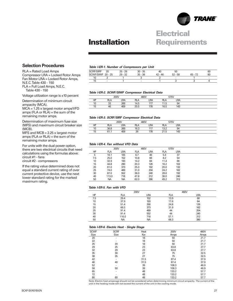
Table I-ER-6. Electric Heat - Single Stage
SCWF SCRF Heat 200V 460VSize Size Kw Amps Amps20 - 18 50 21.722 - 18 50 21.725 20 18 50 21.729 25 23 63.8 27.732 29 23 63.8 27.735 30 27 75 32.538 35 27 75 32.542 - 31.5 87.4 37.946 40 31.5 87.4 37.952 - 39 108.3 46.958 50 39 108.3 46.965 - 48 133.2 57.772 - 48 133.2 57.780 60 48 133.2 57.7
Note: Electric heat amperage should not be considered when determining minimum circuit ampacity. The current of theunit in the heating mode will not exceed the current of the unit in the cooling mode.
Selection Procedures
RLA = Rated Load AmpsCompressor LRA = Locked Rotor AmpsFan Motor LRA = Locked Rotor Amps,N.E.C. Table 430 - 150FLA = Full Load Amps, N.E.C.
Table 430 - 150
Voltage utilization range is ±10 percent
Determination of minimum circuitampacity (MCA).MCA = 1.25 x largest motor amps/VFDamps (FLA or RLA) + the sum of theremaining motor amps.
Determination of maximum fuse size(MFS) and maximum circuit breaker size(MCB).MFS and MCB = 2.25 x largest motoramps (FLA or RLA) + the sum of theremaining motor amps.
For units with the dual power option,there are two electrical circuits that needcalculations using the formulas above:circuit #1 - fanscircuit #2 - compressors
If the rating value determined does notequal a standard current rating of overcurrent protective device, use the nextlower standard rating for the markedmaximum rating.
Table I-ER-1. Number of Compressors per Unit
SCRF/SIRF 20 25 - 29 30 - 35 40 50 60SCWF/SIWF 20 - 25 29 - 32 35 - 38 42 - 46 52 - 58 65 - 72 80
10 2 1 3 2 - 1 -15 - 1 - 1 3 3 4
Table I-ER-2. SCWF/SIWF Compressor Electrical Data
200V 460V 575VHP RLA LRA RLA LRA RLA LRA10 33 269 14.5 117 11.5 9415 46 409 20.5 178 16.5 143
Table I-ER-3. SCRF/SIRF Compressor Electrical Data
200V 460V 575VHP RLA LRA RLA LRA RLA LRA10 36.8 269 16.3 117 13.2 9415 61.1 409 26 178 21.5 143
Table I-ER-4. Fan without VFD Data
200V 460V 575VHP FLA LRA FLA LRA FLA LRA5 16.1 105 6.7 46 5.4 37
7.5 25.0 152 10.8 66 8.2 5410 32.9 193 14.2 84 11.4 6615 44.8 290 20.3 126 16.2 10220 61.0 373 25.0 162 20.0 13225 74.0 469 31.0 204 24.2 16230 87.0 552 36.0 240 28.6 19240 113.0 718 47.8 312 38.0 24650 NA NA 62.0 390 49.2 312
Table I-ER-5. Fan with VFD
200V 460VHP FLA LRA FLA LRA7.5 29.4 152 13.9 6610 37.9 193 17.6 8415 51.4 290 24.8 12620 66.5 373 31.9 16225 91.4 469 44 20430 91.4 552 44 24040 116.0 718 57.1 31250 NA NA 68.3 390
Installation
28 SCXF-SVX01B-EN
Pre-StartupRequirements
Pre-Startup Procedures
Before starting up units perform thefollowing procedures to ensure properunit operation.
Unit Protective CoversRemove the shipping protectioncoverings from the human interfacepanel (HI) at the control panel, the filterbox (or air inlet opening), the dischargeair opening, and optional variablefrequency drive (VFD).
Compressor IsolatorsLoosen compressor isolator mountingbolts and remove shipping bracket frombeneath the compressor feet. Retightenisolator mounting bolts. Torque to 18 ft.lbs. (+ 2 ft. Lbs.)
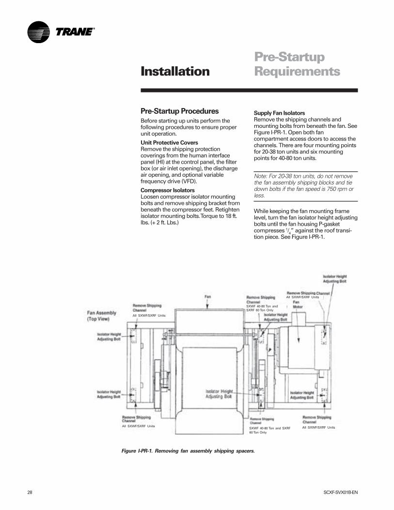
Supply Fan IsolatorsRemove the shipping channels andmounting bolts from beneath the fan. SeeFigure I-PR-1. Open both fancompartment access doors to access thechannels. There are four mounting pointsfor 20-38 ton units and six mountingpoints for 40-80 ton units.
Note: For 20-38 ton units, do not removethe fan assembly shipping blocks and tiedown bolts if the fan speed is 750 rpm orless.
While keeping the fan mounting framelevel, turn the fan isolator height adjustingbolts until the fan housing P-gasketcompresses 1/4” against the roof transi-tion piece. See Figure I-PR-1.
Installation
Figure I-PR-1. Removing fan assembly shipping spacers.
SXWF 40-80 Ton and SXRF60 Ton Only
SXWF 40-80 Ton andSXRF 60 Ton Only
All SXWF/SXRF Units All SXWF/SXRF Units
All SXWF/SXRF Units
All SXWF/SXRF Units
SCXF-SVX01B-EN 29
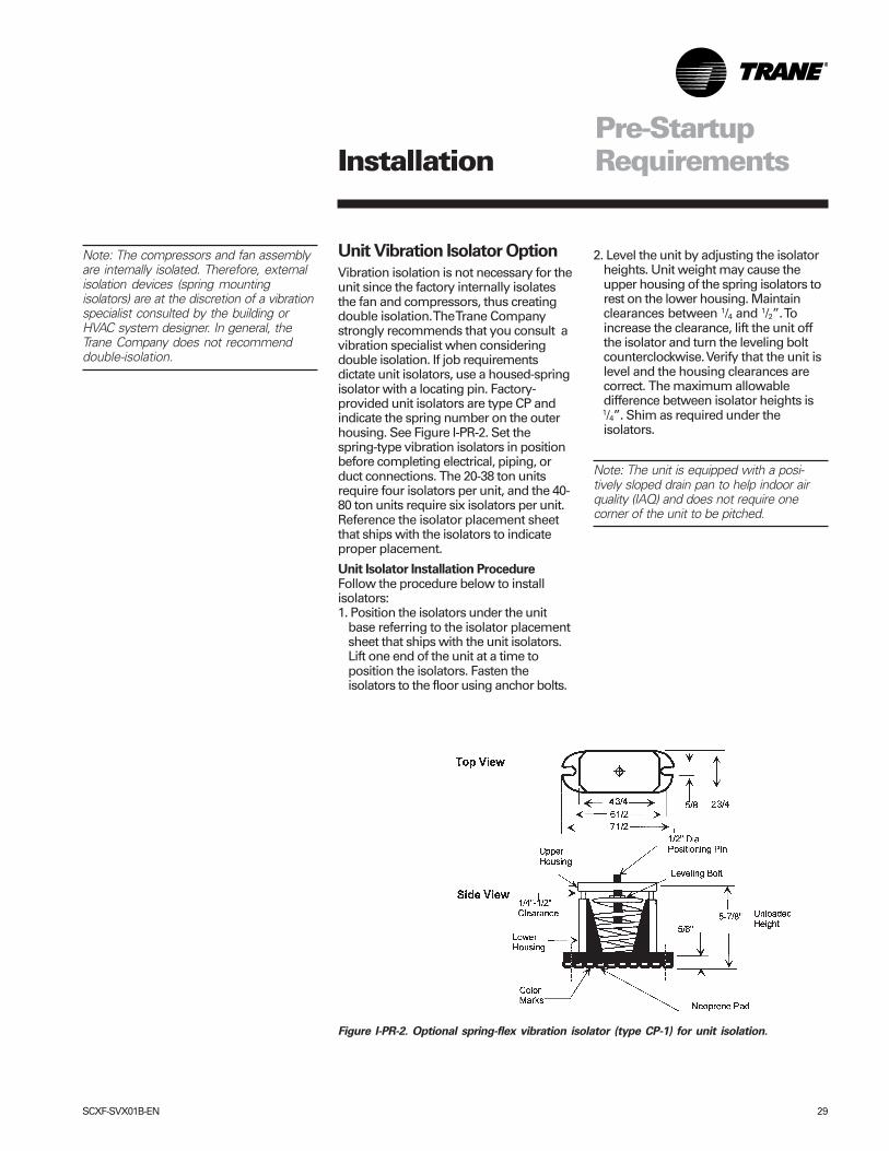
Unit Vibration Isolator Option
Vibration isolation is not necessary for theunit since the factory internally isolatesthe fan and compressors, thus creatingdouble isolation. The Trane Companystrongly recommends that you consult avibration specialist when consideringdouble isolation. If job requirementsdictate unit isolators, use a housed-springisolator with a locating pin. Factory-provided unit isolators are type CP andindicate the spring number on the outerhousing. See Figure I-PR-2. Set thespring-type vibration isolators in positionbefore completing electrical, piping, orduct connections. The 20-38 ton unitsrequire four isolators per unit, and the 40-80 ton units require six isolators per unit.Reference the isolator placement sheetthat ships with the isolators to indicateproper placement.
Unit Isolator Installation ProcedureFollow the procedure below to installisolators:1. Position the isolators under the unit
base referring to the isolator placementsheet that ships with the unit isolators.Lift one end of the unit at a time toposition the isolators. Fasten theisolators to the floor using anchor bolts.
2. Level the unit by adjusting the isolatorheights. Unit weight may cause theupper housing of the spring isolators torest on the lower housing. Maintainclearances between 1/4 and 1/2”. Toincrease the clearance, lift the unit offthe isolator and turn the leveling boltcounterclockwise. Verify that the unit islevel and the housing clearances arecorrect. The maximum allowabledifference between isolator heights is
1/4”. Shim as required under theisolators.
Note: The unit is equipped with a posi-tively sloped drain pan to help indoor airquality (IAQ) and does not require onecorner of the unit to be pitched.
Figure I-PR-2. Optional spring-flex vibration isolator (type CP-1) for unit isolation.
Note: The compressors and fan assemblyare internally isolated. Therefore, externalisolation devices (spring mountingisolators) are at the discretion of a vibrationspecialist consulted by the building orHVAC system designer. In general, theTrane Company does not recommenddouble-isolation.
Pre-StartupRequirementsInstallation
30 SCXF-SVX01B-EN
Pre-StartupRequirements
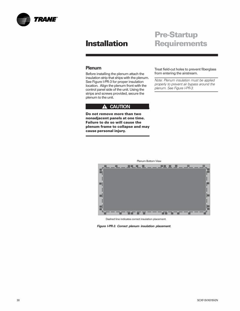
Plenum
Before installing the plenum attach theinsulation strip that ships with the plenum.See Figure I-PR-3 for proper insulationlocation. Align the plenum front with thecontrol panel side of the unit. Using thestrips and screws provided, secure theplenum to the unit.
Do not remove more than twononadjacent panels at one time.Failure to do so will cause theplenum frame to collapse and maycause personal injury.
Treat field-cut holes to prevent fiberglassfrom entering the airstream.
Note: Plenum insulation must be appliedproperly to prevent air bypass around theplenum. See Figure I-PR-3.
Figure I-PR-3. Correct plenum insulation placement.
Plenum Bottom View
Dashed line indicates correct insulation placement.
����� CAUTION!
Installation
SCXF-SVX01B-EN 31
Pre-StartupRequirements
Hydronic Coil Installation
Steam and Hot Water Coil
Note: The hydronic coil options are alsoavailable factory mounted.
1. Position the coil box behind the unitwith open side facing the unit inlet.
2. An envelope containing the gasket andmounting screws to attach the coil tothe unit ships in the bottom of the unit.Install the pressure sensitive gasket tothe unit side of the vertical flange on thecoil box in two places.
3. Remove the six two-inch filter adaptersfrom filter rack when using four-inchfilters.
4. Before attaching the coil box, connectthe coil duct static pressure tube. Thismust be done before the coil box isbolted to the unit. If the unit connectiondoes not have a static pressure tube,
then no connection is required.5. Apply the edge protector to the flange
on the unit. Remove knockout on theunit filter cover and install the bushingin the plastic bag. Run the wires throughthe bushing and connect wires to theunit.
6. After connecting wires and the staticpressure tube, raise the coil box upagainst the unit and install the mountingscrews. Recommended lifting pointsare at each end of the coil box.
7. Avoid routing wires over devices andsharp edges. Use wire ties about every12 inches to secure wires to other wireharnesses.
8. Move the entering air temperaturesensor upsteam of the coil to ensureproper operation.
Installation
32 SCXF-SVX01B-EN
Pre-StartupRequirements
Airside Economizer Installation
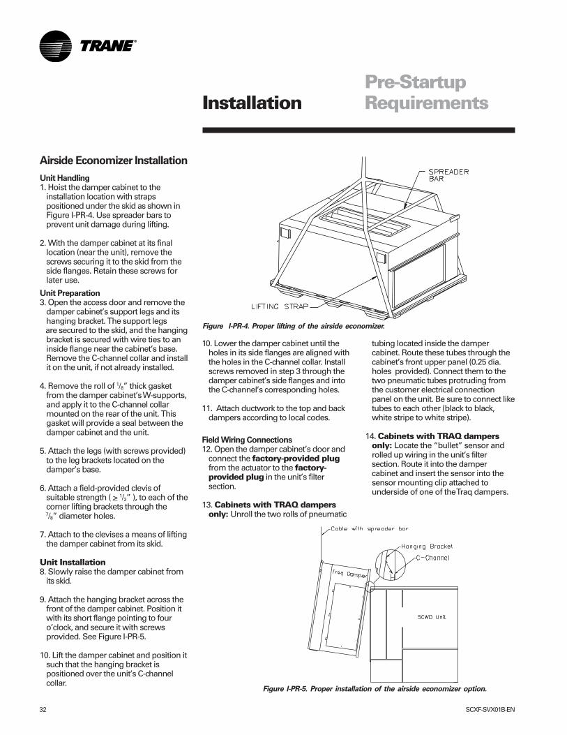
Unit Handling1. Hoist the damper cabinet to the
installation location with strapspositioned under the skid as shown inFigure I-PR-4. Use spreader bars toprevent unit damage during lifting.
2. With the damper cabinet at its finallocation (near the unit), remove thescrews securing it to the skid from theside flanges. Retain these screws forlater use.
Unit Preparation3. Open the access door and remove the
damper cabinet’s support legs and itshanging bracket. The support legs
are secured to the skid, and the hangingbracket is secured with wire ties to aninside flange near the cabinet’s base.Remove the C-channel collar and installit on the unit, if not already installed.
4. Remove the roll of 1/8” thick gasketfrom the damper cabinet’s W-supports,and apply it to the C-channel collarmounted on the rear of the unit. Thisgasket will provide a seal between thedamper cabinet and the unit.
5. Attach the legs (with screws provided)to the leg brackets located on thedamper’s base.
6. Attach a field-provided clevis ofsuitable strength ( > 1/2” ), to each of thecorner lifting brackets through the
7/8” diameter holes.
7. Attach to the clevises a means of liftingthe damper cabinet from its skid.
Unit Installation8. Slowly raise the damper cabinet from
its skid.
9. Attach the hanging bracket across thefront of the damper cabinet. Position itwith its short flange pointing to fouro’clock, and secure it with screwsprovided. See Figure I-PR-5.
10. Lift the damper cabinet and position itsuch that the hanging bracket ispositioned over the unit’s C-channelcollar.
Figure I-PR-4. Proper lifting of the airside economizer.
10. Lower the damper cabinet until theholes in its side flanges are aligned withthe holes in the C-channel collar. Installscrews removed in step 3 through thedamper cabinet’s side flanges and intothe C-channel’s corresponding holes.
11. Attach ductwork to the top and backdampers according to local codes.
Field Wiring Connections12. Open the damper cabinet’s door and
connect the factory-provided plugfrom the actuator to the factory-provided plug in the unit’s filtersection.
13. Cabinets with TRAQ dampersonly: Unroll the two rolls of pneumatic
Figure I-PR-5. Proper installation of the airside economizer option.
tubing located inside the dampercabinet. Route these tubes through thecabinet’s front upper panel (0.25 dia.holes provided). Connect them to thetwo pneumatic tubes protruding fromthe customer electrical connectionpanel on the unit. Be sure to connect liketubes to each other (black to black,white stripe to white stripe).
14. Cabinets with TRAQ dampersonly: Locate the “bullet” sensor androlled up wiring in the unit’s filtersection. Route it into the dampercabinet and insert the sensor into thesensor mounting clip attached tounderside of one of the Traq dampers.
Installation
SCXF-SVX01B-EN 33
Pre-StartupRequirements
Static Pressure TransducerInstallation (VAV units only)
Supply air static pressure controls theinlet guide vane and inverter options. Astatic pressure head assembly shipsseparate in the control panel for fieldinstallation in the supply air duct work.The installer is responsible for providingpneumatic tubing.
Transducer LocationPlace the head assembly in an area of theductwork that will provide an averageand evenly distributed airflow pattern.Use the following guidelines to determinean appropriate installation location.
1. Locate the static head assembly abouttwo-thirds to three- fourths of the waydown the longest duct run, in an areaapproximately 10 duct diametersdownstream and 2 duct diametersupstream of any major interferences,turns, or changes in duct diameter.
2. When installing pneumatic tubingbetween the head assembly andtransducer in the control panel, do notexceed 250 feet for 1/4” OD tubing or500 feet for 3/8” OD tubing.
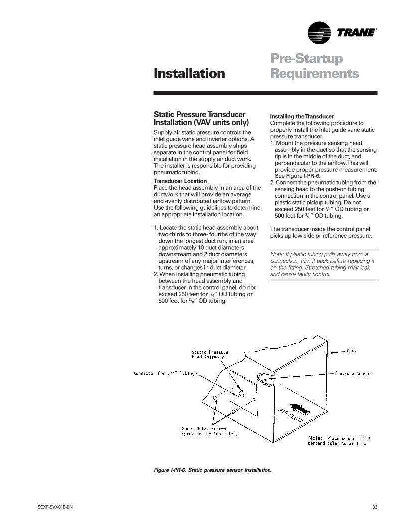
Installing the TransducerComplete the following procedure toproperly install the inlet guide vane staticpressure transducer.1. Mount the pressure sensing head
assembly in the duct so that the sensingtip is in the middle of the duct, andperpendicular to the airflow. This willprovide proper pressure measurement.See Figure I-PR-6.
2. Connect the pneumatic tubing from thesensing head to the push-on tubingconnection in the control panel. Use aplastic static pickup tubing. Do notexceed 250 feet for 1/4“ OD tubing or500 feet for 3/8” OD tubing.
The transducer inside the control panelpicks up low side or reference pressure.
Note: If plastic tubing pulls away from aconnection, trim it back before replacing iton the fitting. Stretched tubing may leakand cause faulty control.
Figure I-PR-6. Static pressure sensor installation.
Installation
34 SCXF-SVX01B-EN
Pre-StartupRequirements
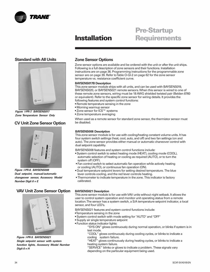
Figure I-PR-7. BAYSENS017
Zone Temperature Sensor Only
Standard with All Units Zone Sensor Options
Zone sensor options are available and be ordered with the unit or after the unit ships.Following is a full description of zone sensors and their functions. Installationinstructions are on page 36. Programming instructions for the programmable zonesensor are on page 39. Refer to Table O-GI-2 on page 62 for the zone sensortemperature vs. resistance coefficient curve.
BAYSENS017B DescriptionThis zone sensor module ships with all units, and can be used with BAYSENS019,BAYSENS020, or BAYSENS021 remote sensors. When this sensor is wired to one ofthese remote zone sensors, wiring must be 18 AWG shielded twisted pair (Belden 8760or equivalent). Refer to the specific zone sensor for wiring details. It provides thefollowing features and system control functions:• Remote temperature sensing in the zone• Morning warmup sensor• Zone sensor for ICS™ systems• Zone temperature averaging
When used as a remote sensor for standard zone sensor, the thermistor sensor mustbe disabled.
Figure I-PR-9. BAYSENS021
Single setpoint sensor with system
function lights, Accessory Model Number
Digit 6 = H
BAYSENS021 DescriptionThis zone sensor module is for use with VAV units without night setback. It allows theuser to control system operation and monitor unit operating status from a remotelocation. The sensor has a system switch, a S/A temperature setpoint indicator, a localsensor, and four LED’s.
BAYSENS021 features and system control functions include:• Temperature sensing in the zone• System control switch with mode setting for "AUTO" and "OFF"• Supply air single temperature setpoint• Function status indicator lights:
“SYS ON” glows continuously during normal operation, or blinks if system is intest mode.“COOL” glows continuously during cooling cycles, or blinks to indicate acooling system failure.“HEAT” glows continuously during heating cycles, or blinks to indicate aheating system failure.“SERVICE” blinks or glows to indicate a problem. These signals varydepending on the particular equipment being used.
VAV Unit Zone Sensor Option
CV Unit Zone Sensor Option
Figure I-PR-8. BAYSENS008
Dual setpoint, manual/automatic
changeover sensor, Accessory Model
Number Digit 6 = E
BAYSENS008 DescriptionThis zone sensor module is for use with cooling/heating constant volume units. It hasfour system switch settings (heat, cool, auto, and off) and two fan settings (on andauto). The zone sensor provides either manual or automatic chaneover control withdual setpoint capability.
BAYSENS008 features and system control functions include:• System control switch to select heating mode (HEAT), cooling mode (COOL),
automatic selection of heating or cooling as required (AUTO), or to turn thesystem off (OFF).
• Fan control switch to select automatic fan operation while actively heatingor cooling (AUTO), or continuous fan operation (ON).
• Dual temperature setpoint levers for setting desired temperature. The bluelever controls cooling, and the red lever controls heating.
• Thermometer to indicate temperature in the zone. This indicator is factorycalibrated.
Installation
SCXF-SVX01B-EN 35
Pre-StartupRequirements
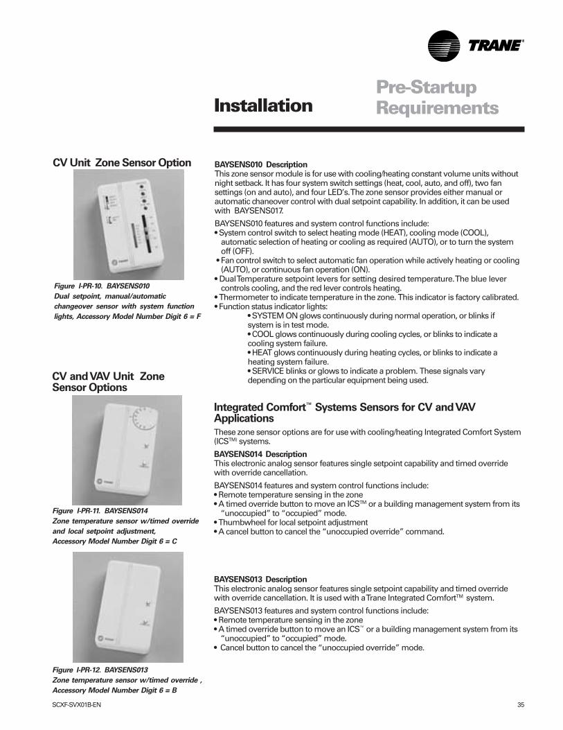
Figure I-PR-12. BAYSENS013
Zone temperature sensor w/timed override ,
Accessory Model Number Digit 6 = B
Figure I-PR-11. BAYSENS014
Zone temperature sensor w/timed override
and local setpoint adjustment,
Accessory Model Number Digit 6 = C
Figure I-PR-10. BAYSENS010
Dual setpoint, manual/automatic
changeover sensor with system function
lights, Accessory Model Number Digit 6 = F
CV Unit Zone Sensor Option BAYSENS010 DescriptionThis zone sensor module is for use with cooling/heating constant volume units withoutnight setback. It has four system switch settings (heat, cool, auto, and off), two fansettings (on and auto), and four LED’s. The zone sensor provides either manual orautomatic chaneover control with dual setpoint capability. In addition, it can be usedwith BAYSENS017.
BAYSENS010 features and system control functions include:• System control switch to select heating mode (HEAT), cooling mode (COOL),
automatic selection of heating or cooling as required (AUTO), or to turn the systemoff (OFF).
• Fan control switch to select automatic fan operation while actively heating or cooling(AUTO), or continuous fan operation (ON).
• Dual Temperature setpoint levers for setting desired temperature. The blue levercontrols cooling, and the red lever controls heating.
• Thermometer to indicate temperature in the zone. This indicator is factory calibrated.• Function status indicator lights:
• SYSTEM ON glows continuously during normal operation, or blinks ifsystem is in test mode.• COOL glows continuously during cooling cycles, or blinks to indicate acooling system failure.• HEAT glows continuously during heating cycles, or blinks to indicate aheating system failure.• SERVICE blinks or glows to indicate a problem. These signals varydepending on the particular equipment being used.
Integrated Comfort™ Systems Sensors for CV and VAVApplications
These zone sensor options are for use with cooling/heating Integrated Comfort System(ICSTM) systems.
BAYSENS014 DescriptionThis electronic analog sensor features single setpoint capability and timed overridewith override cancellation.
BAYSENS014 features and system control functions include:• Remote temperature sensing in the zone• A timed override button to move an ICSTM or a building management system from its
“unoccupied” to “occupied” mode.• Thumbwheel for local setpoint adjustment• A cancel button to cancel the “unoccupied override” command.
BAYSENS013 DescriptionThis electronic analog sensor features single setpoint capability and timed overridewith override cancellation. It is used with a Trane Integrated ComfortTM system.
BAYSENS013 features and system control functions include:• Remote temperature sensing in the zone• A timed override button to move an ICS™ or a building management system from its
“unoccupied” to “occupied” mode.• Cancel button to cancel the “unoccupied override” mode.
CV and VAV Unit ZoneSensor Options
Installation
36 SCXF-SVX01B-EN
Note: Guidelines for wire sizes andlengths are shown in Table PS-1. The totalresistance of these low voltage wiresmust not exceed 2.5 ohms per conductor.Any resistance greater than 2.5 ohms maycause the control to malfunction due toexcessive voltage drop.
Note: Do not run low-voltage controlwiring in same conduit with high-voltagepower wiring.
1. Run wires between the unit controlpanel and the zone sensor subbase. Todetermine the number of wiresrequired, refer to the unit wiringdiagrams.
2. Connect the wiring to the appropriateterminals at the unit control panel andat the zone sensor subbase. In general,zone sensor connections to the unit usethe convention of connecting zonesensor terminals to like numbered unitterminals (1 to 1, 2 to 2, etc.). Theconnection detail is shown on the unitwiring diagrams, which are located inthe unit control panel.
3. Replace the zone sensor cover backon the subbase and snap securely intoplace.
Standard Remote Sensor(BAYSENS017)When using the remote sensor,BAYSENS017, mount it in the space thatis to be controlled. Wire according to theinterconnecting wiring diagrams on theunit.
Table I-PR-1. Zone Sensor Maximum
Lengths and Wire Size
Distance from RecommendedUnit to Controller Wiring Size0-150 feet 22 gauge151--240 feet 20 gauge241-385 feet 18 gauge386- 610 feet 16 gauge611-970 feet 14 gauge
Pre-StartupRequirements
Zone Sensor Installation
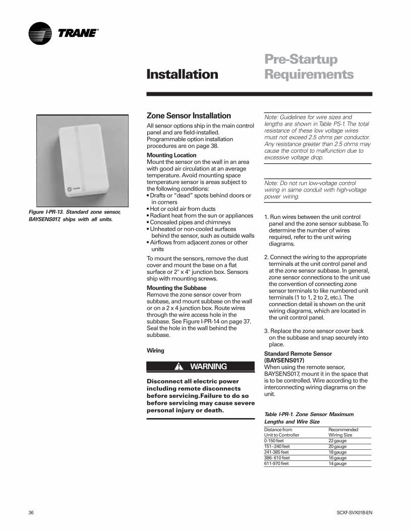
All sensor options ship in the main controlpanel and are field-installed.Programmable option installationprocedures are on page 38.
Mounting LocationMount the sensor on the wall in an areawith good air circulation at an averagetemperature. Avoid mounting spacetemperature sensor is areas subject tothe following conditions:• Drafts or “dead” spots behind doors or
in corners• Hot or cold air from ducts• Radiant heat from the sun or appliances• Concealed pipes and chimneys• Unheated or non-cooled surfaces
behind the sensor, such as outside walls• Airflows from adjacent zones or other
units
To mount the sensors, remove the dustcover and mount the base on a flatsurface or 2" x 4" junction box. Sensorsship with mounting screws.
Mounting the SubbaseRemove the zone sensor cover fromsubbase, and mount subbase on the wallor on a 2 x 4 junction box. Route wiresthrough the wire access hole in thesubbase. See Figure I-PR-14 on page 37.Seal the hole in the wall behind thesubbase.
Wiring
Disconnect all electric powerincluding remote disconnectsbefore servicing.Failure to do sobefore servicing may cause severepersonal injury or death.
Figure I-PR-13. Standard zone sensor,
BAYSENS017, ships with all units.
����� WARNING!
Installation
SCXF-SVX01B-EN 37
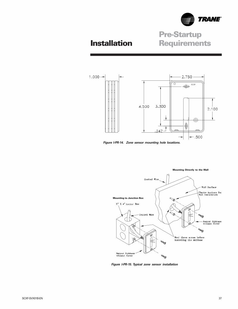
Figure I-PR-15. Typical zone sensor installation
Pre-StartupRequirements
Figure I-PR-14. Zone sensor mounting hole locations.
Junction
Installation
Mounting to Junction Box
Mounting Directly to the Wall
38 SCXF-SVX01B-EN
Pre-StartupRequirements
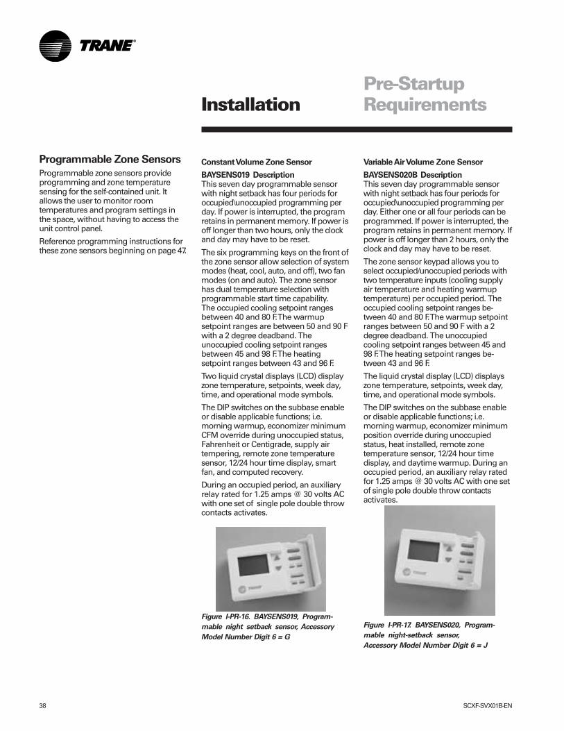
Constant Volume Zone Sensor
BAYSENS019 DescriptionThis seven day programmable sensorwith night setback has four periods foroccupied\unoccupied programming perday. If power is interrupted, the programretains in permanent memory. If power isoff longer than two hours, only the clockand day may have to be reset.
The six programming keys on the front ofthe zone sensor allow selection of systemmodes (heat, cool, auto, and off), two fanmodes (on and auto). The zone sensorhas dual temperature selection withprogrammable start time capability.The occupied cooling setpoint rangesbetween 40 and 80 F. The warmupsetpoint ranges are between 50 and 90 Fwith a 2 degree deadband. Theunoccupied cooling setpoint rangesbetween 45 and 98 F. The heatingsetpoint ranges between 43 and 96 F.
Two liquid crystal displays (LCD) displayzone temperature, setpoints, week day,time, and operational mode symbols.
The DIP switches on the subbase enableor disable applicable functions; i.e.morning warmup, economizer minimumCFM override during unoccupied status,Fahrenheit or Centigrade, supply airtempering, remote zone temperaturesensor, 12/24 hour time display, smartfan, and computed recovery.
During an occupied period, an auxiliaryrelay rated for 1.25 amps @ 30 volts ACwith one set of single pole double throwcontacts activates.
Figure I-PR-16. BAYSENS019, Program-
mable night setback sensor, Accessory
Model Number Digit 6 = G
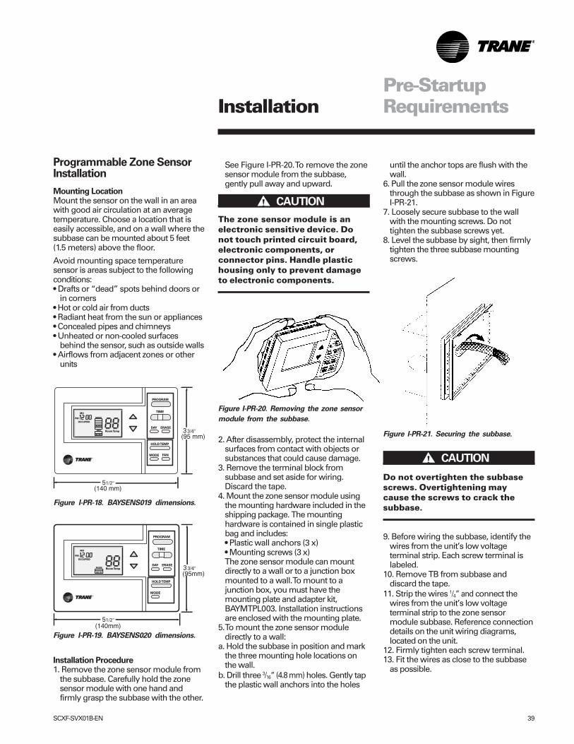
Variable Air Volume Zone Sensor
BAYSENS020B DescriptionThis seven day programmable sensorwith night setback has four periods foroccupied\unoccupied programming perday. Either one or all four periods can beprogrammed. If power is interrupted, theprogram retains in permanent memory. Ifpower is off longer than 2 hours, only theclock and day may have to be reset.
The zone sensor keypad allows you toselect occupied/unoccupied periods withtwo temperature inputs (cooling supplyair temperature and heating warmuptemperature) per occupied period. Theoccupied cooling setpoint ranges be-tween 40 and 80 F. The warmup setpointranges between 50 and 90 F with a 2degree deadband. The unoccupiedcooling setpoint ranges between 45 and98 F. The heating setpoint ranges be-tween 43 and 96 F.
The liquid crystal display (LCD) displayszone temperature, setpoints, week day,time, and operational mode symbols.
The DIP switches on the subbase enableor disable applicable functions; i.e.morning warmup, economizer minimumposition override during unoccupiedstatus, heat installed, remote zonetemperature sensor, 12/24 hour timedisplay, and daytime warmup. During anoccupied period, an auxiliary relay ratedfor 1.25 amps @ 30 volts AC with one setof single pole double throw contactsactivates.
Figure I-PR-17. BAYSENS020, Program-
mable night-setback sensor,
Accessory Model Number Digit 6 = J
Programmable Zone Sensors
Programmable zone sensors provideprogramming and zone temperaturesensing for the self-contained unit. Itallows the user to monitor roomtemperatures and program settings inthe space, without having to access theunit control panel.
Reference programming instructions forthese zone sensors beginning on page 47.
Installation
SCXF-SVX01B-EN 39
until the anchor tops are flush with thewall.
6. Pull the zone sensor module wiresthrough the subbase as shown in FigureI-PR-21.
7. Loosely secure subbase to the wallwith the mounting screws. Do nottighten the subbase screws yet.
8. Level the subbase by sight, then firmlytighten the three subbase mountingscrews.
Do not overtighten the subbasescrews. Overtightening maycause the screws to crack thesubbase.
9. Before wiring the subbase, identify thewires from the unit’s low voltageterminal strip. Each screw terminal islabeled.
10. Remove TB from subbase anddiscard the tape.
11. Strip the wires 1/4” and connect thewires from the unit’s low voltageterminal strip to the zone sensormodule subbase. Reference connectiondetails on the unit wiring diagrams,located on the unit.
12. Firmly tighten each screw terminal.13. Fit the wires as close to the subbase
as possible.
Pre-StartupRequirements
Programmable Zone SensorInstallation
Mounting LocationMount the sensor on the wall in an areawith good air circulation at an averagetemperature. Choose a location that iseasily accessible, and on a wall where thesubbase can be mounted about 5 feet(1.5 meters) above the floor.
Avoid mounting space temperaturesensor is areas subject to the followingconditions:• Drafts or “dead” spots behind doors or
in corners• Hot or cold air from ducts• Radiant heat from the sun or appliances• Concealed pipes and chimneys• Unheated or non-cooled surfaces
behind the sensor, such as outside walls• Airflows from adjacent zones or other
units
(140 mm)
(95 mm)
(140mm)
(95mm)
Installation Procedure1. Remove the zone sensor module from
the subbase. Carefully hold the zonesensor module with one hand andfirmly grasp the subbase with the other.
See Figure I-PR-20. To remove the zonesensor module from the subbase,gently pull away and upward.
The zone sensor module is anelectronic sensitive device. Donot touch printed circuit board,electronic components, orconnector pins. Handle plastichousing only to prevent damageto electronic components.
2. After disassembly, protect the internalsurfaces from contact with objects orsubstances that could cause damage.
3. Remove the terminal block fromsubbase and set aside for wiring.Discard the tape.
4. Mount the zone sensor module usingthe mounting hardware included in theshipping package. The mountinghardware is contained in single plasticbag and includes:• Plastic wall anchors (3 x)• Mounting screws (3 x)The zone sensor module can mountdirectly to a wall or to a junction boxmounted to a wall. To mount to ajunction box, you must have themounting plate and adapter kit,BAYMTPL003. Installation instructionsare enclosed with the mounting plate.
5. To mount the zone sensor moduledirectly to a wall:
a. Hold the subbase in position and markthe three mounting hole locations onthe wall.
b. Drill three 3/16” (4.8 mm) holes. Gently tapthe plastic wall anchors into the holes
Figure I-PR-21. Securing the subbase.
Figure I-PR-20. Removing the zone sensor
module from the subbase.
����� CAUTION!
����� CAUTION!
Installation
Figure I-PR-18. BAYSENS019 dimensions.
Figure I-PR-19. BAYSENS020 dimensions.
40 SCXF-SVX01B-EN
Pre-StartupRequirements
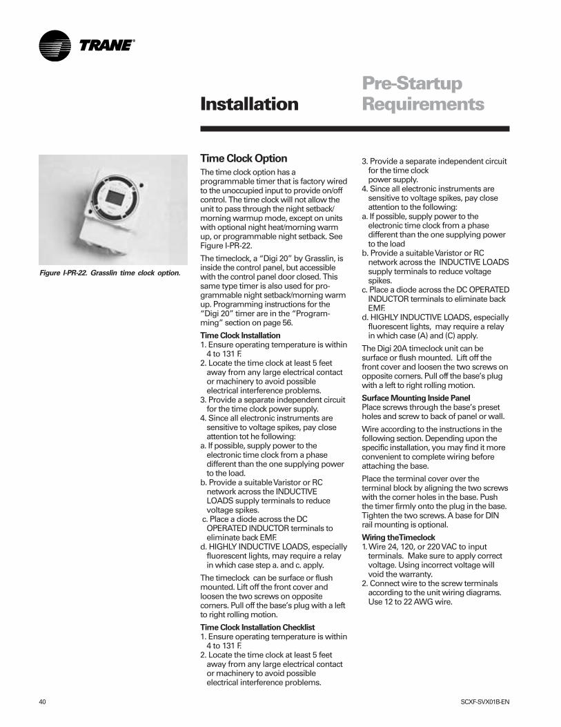
Time Clock Option
The time clock option has aprogrammable timer that is factory wiredto the unoccupied input to provide on/offcontrol. The time clock will not allow theunit to pass through the night setback/morning warmup mode, except on unitswith optional night heat/morning warmup, or programmable night setback. SeeFigure I-PR-22.
The timeclock, a “Digi 20” by Grasslin, isinside the control panel, but accessiblewith the control panel door closed. Thissame type timer is also used for pro-grammable night setback/morning warmup. Programming instructions for the“Digi 20” timer are in the “Program-ming” section on page 56.
Time Clock Installation1. Ensure operating temperature is within
4 to 131 F.2. Locate the time clock at least 5 feet
away from any large electrical contactor machinery to avoid possibleelectrical interference problems.
3. Provide a separate independent circuitfor the time clock power supply.
4. Since all electronic instruments aresensitive to voltage spikes, pay closeattention tot he following:
a. If possible, supply power to theelectronic time clock from a phasedifferent than the one supplying powerto the load.
b. Provide a suitable Varistor or RCnetwork across the INDUCTIVELOADS supply terminals to reducevoltage spikes.
c. Place a diode across the DCOPERATED INDUCTOR terminals toeliminate back EMF.
d. HIGHLY INDUCTIVE LOADS, especiallyfluorescent lights, may require a relayin which case step a. and c. apply.
The timeclock can be surface or flushmounted. Lift off the front cover andloosen the two screws on oppositecorners. Pull off the base’s plug with a leftto right rolling motion.
Time Clock Installation Checklist1. Ensure operating temperature is within
4 to 131 F.2. Locate the time clock at least 5 feet
away from any large electrical contactor machinery to avoid possibleelectrical interference problems.
3. Provide a separate independent circuitfor the time clockpower supply.
4. Since all electronic instruments aresensitive to voltage spikes, pay closeattention to the following:
a. If possible, supply power to theelectronic time clock from a phasedifferent than the one supplying powerto the load
b. Provide a suitable Varistor or RCnetwork across the INDUCTIVE LOADSsupply terminals to reduce voltagespikes.
c. Place a diode across the DC OPERATEDINDUCTOR terminals to eliminate backEMF.
d. HIGHLY INDUCTIVE LOADS, especiallyfluorescent lights, may require a relayin which case (A) and (C) apply.
The Digi 20A timeclock unit can besurface or flush mounted. Lift off thefront cover and loosen the two screws onopposite corners. Pull off the base’s plugwith a left to right rolling motion.
Surface Mounting Inside PanelPlace screws through the base’s presetholes and screw to back of panel or wall.
Wire according to the instructions in thefollowing section. Depending upon thespecific installation, you may find it moreconvenient to complete wiring beforeattaching the base.
Place the terminal cover over theterminal block by aligning the two screwswith the corner holes in the base. Pushthe timer firmly onto the plug in the base.Tighten the two screws. A base for DINrail mounting is optional.
Wiring theTimeclock1. Wire 24, 120, or 220 VAC to input
terminals. Make sure to apply correctvoltage. Using incorrect voltage willvoid the warranty.
2. Connect wire to the screw terminalsaccording to the unit wiring diagrams.Use 12 to 22 AWG wire.
Figure I-PR-22. Grasslin time clock option.
Installation
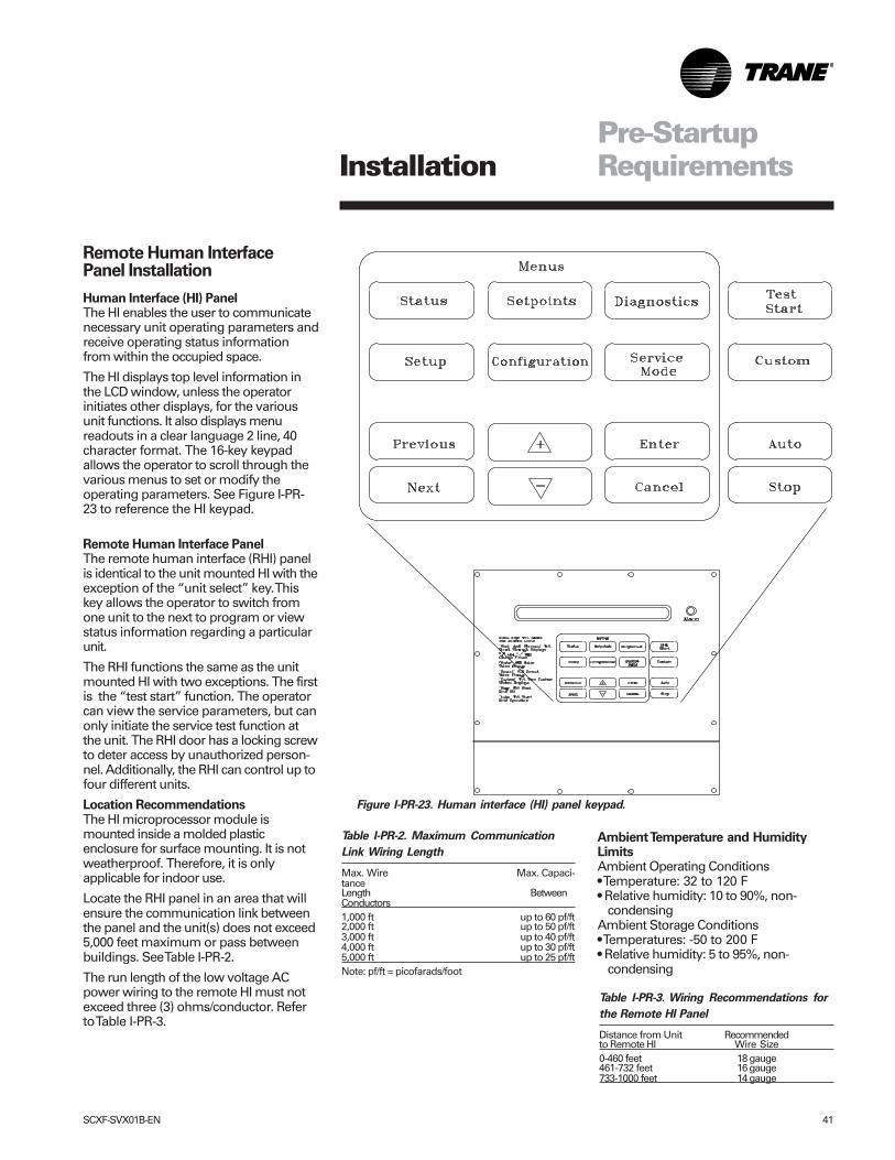
SCXF-SVX01B-EN 41
Pre-StartupRequirements
Figure I-PR-23. Human interface (HI) panel keypad.
Remote Human InterfacePanel Installation
Human Interface (HI) PanelThe HI enables the user to communicatenecessary unit operating parameters andreceive operating status informationfrom within the occupied space.
The HI displays top level information inthe LCD window, unless the operatorinitiates other displays, for the variousunit functions. It also displays menureadouts in a clear language 2 line, 40character format. The 16-key keypadallows the operator to scroll through thevarious menus to set or modify theoperating parameters. See Figure I-PR-23 to reference the HI keypad.
Remote Human Interface PanelThe remote human interface (RHI) panelis identical to the unit mounted HI with theexception of the “unit select” key. Thiskey allows the operator to switch fromone unit to the next to program or viewstatus information regarding a particularunit.
The RHI functions the same as the unitmounted HI with two exceptions. The firstis the “test start” function. The operatorcan view the service parameters, but canonly initiate the service test function atthe unit. The RHI door has a locking screwto deter access by unauthorized person-nel. Additionally, the RHI can control up tofour different units.
Location RecommendationsThe HI microprocessor module ismounted inside a molded plasticenclosure for surface mounting. It is notweatherproof. Therefore, it is onlyapplicable for indoor use.
Locate the RHI panel in an area that willensure the communication link betweenthe panel and the unit(s) does not exceed5,000 feet maximum or pass betweenbuildings. See Table I-PR-2.
The run length of the low voltage ACpower wiring to the remote HI must notexceed three (3) ohms/conductor. Referto Table I-PR-3.
Ambient Temperature and HumidityLimitsAmbient Operating Conditions• Temperature: 32 to 120 F• Relative humidity: 10 to 90%, non-
condensingAmbient Storage Conditions• Temperatures: -50 to 200 F• Relative humidity: 5 to 95%, non-
condensing
Table I-PR-2. Maximum Communication
Link Wiring Length
Max. Wire Max. Capaci-tanceLength BetweenConductors1,000 ft up to 60 pf/ft2,000 ft up to 50 pf/ft3,000 ft up to 40 pf/ft4,000 ft up to 30 pf/ft5,000 ft up to 25 pf/ftNote: pf/ft = picofarads/foot
Table I-PR-3. Wiring Recommendations for
the Remote HI Panel
Distance from Unit Recommendedto Remote HI Wire Size0-460 feet 18 gauge461-732 feet 16 gauge733-1000 feet 14 gauge
Installation
42 SCXF-SVX01B-EN
Pre-StartupRequirements
Mounting the Remote HumanInterface (RHI) Panel
The installer must provide all mountinghardware such as; hand tools, electricalboxes, conduit, screws, etc. Refer toFigure I-PR-24 on page 43 for themounting hole and knockout locations.
ProcedureRefer to Figure I-PR-24 on page 43 andfollow the procedure below for mountingthe remote HI panel on a 4” by 4”electrical junction box. Place themicroprocessor in a clean dry locationduring the enclosure mountingprocedures to prevent damage.
1. Mount an electrical junction box in thewall so that the front edge of the boxwill be flush with the finished wallsurface.
2. Prior to mounting the panel, themicroprocessor module must becarefully removed from the enclosure.To remove the module:
a. Lay the remote panel face up on a flatsurface and remove the locking screwfrom the right hand bottom end of thepanel.
b. Remove the recessed hinge screwfrom the left hand bottom end of thepanel.
c. Unlatch the door of the enclosure as ifto open it, and slide the left hand side ofthe door upward away from the hinge.Lay it aside.
d. With the key pad visible, remove thetwo (2) screws located on the righthand side of the key pad.
e. Carefully slide the key pad plateupward from the bottom, releasing theextruded hinge pin from its socket atthe top.
f. Set the microprocessor aside untilmounting is complete.
3. Remove the junction box knockout inthe back of the enclosure.
Note: The top of the enclosure is marked“TOP.”
4. With the enclosure in the correctposition; align the mounting holesaround the knockout in the enclosurewith the screw holes in the electricalhandy box and secure with theappropriate screws.
5. Replace the microprocessor within theenclosure as follows:
a. Verify that the terminal block jumpersare connected properly.
b. Slide the extruded hinge pin at the topleft of the key pad plate into the holelocated at the top left hand side of theenclosure.
c. Slide the bottom of the plate into place,aligning the two (2) clearance holeswith the screw holes on the right. Installthe screws but do not tighten at thistime.
Note: If the two screws are not installed ascalled out in the previous step, holdagainst the key pad plate while installingthe door in the next step, to prevent it fromfalling out.
d. Slide the extruded hinge pin at the topleft of the door into the hole locatedunder the bottom left side of the display.
e. Install and tighten the hinge screwlocated at the bottom left side of theenclosure.
Wall Mounting the RHI Panel1. Prior to mounting the panel, the
microprocessor module must beremoved from the enclosure. Completestep 2 in the previous discussion,“Mounting on a 4 in. x 4 in. ElectricalBox,” before proceeding.
2. With the microprocessor removed,refer to Figure I-PR-24 for the location ofthe mounting holes to be used for wallmounting.
3. Place the enclosure against themounting surface and mark themounting holes.
Note: The top of the enclosure is markedwith “TOP.”
4. With the enclosure in the correctposition, remove the enclosure anddrill the necessary holes in the surfacefor the appropriate fasteners, (plasticanchors, molly bolts, screws, etc.)
5. Remove the necessary knockouts forthe wire or conduit entry beforemounting the panel.
6. Place the enclosure back onto thesurface and secure it with theappropriate screws.
7. Follow step 5 in the previous section,“Mounting on a 4” by 4” ElectricalBox,” to replace the microprocessorwithin the enclosure.
Installation
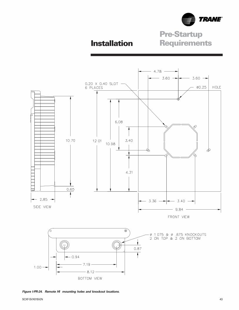
SCXF-SVX01B-EN 43
Pre-StartupRequirements
Figure I-PR-24. Remote HI mounting holes and knockout locations.
Installation
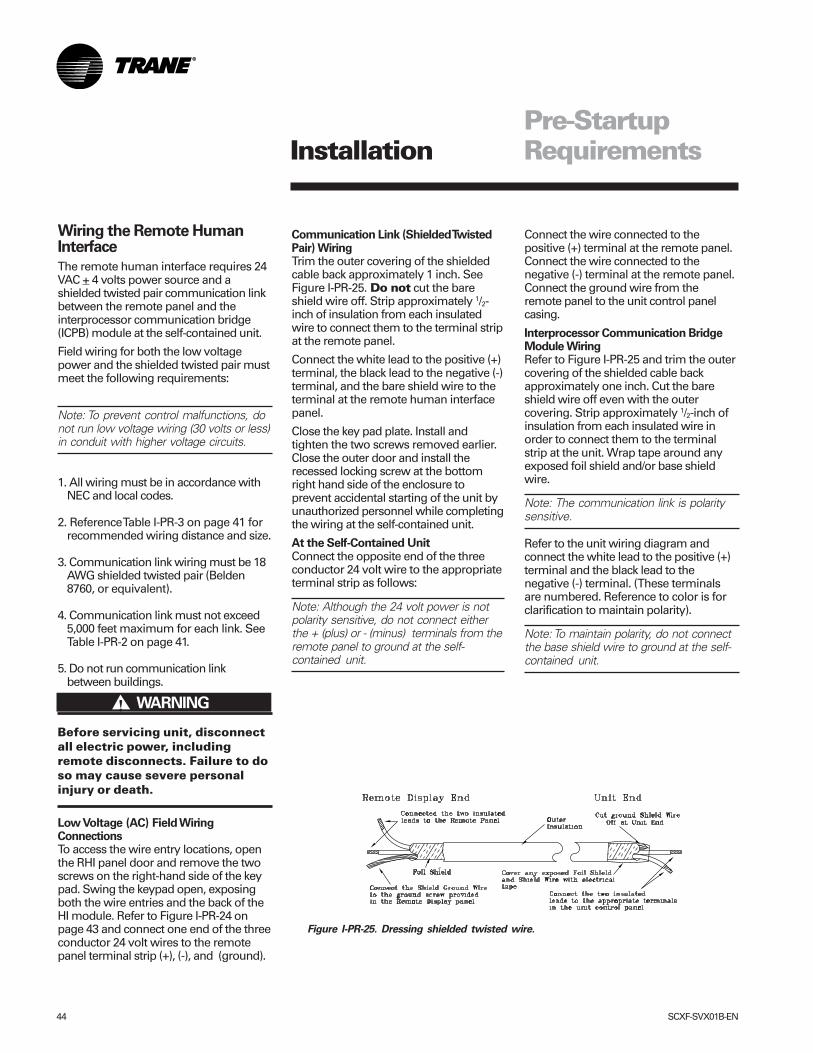
44 SCXF-SVX01B-EN
Wiring the Remote HumanInterface
The remote human interface requires 24VAC + 4 volts power source and ashielded twisted pair communication linkbetween the remote panel and theinterprocessor communication bridge(ICPB) module at the self-contained unit.
Field wiring for both the low voltagepower and the shielded twisted pair mustmeet the following requirements:
Note: To prevent control malfunctions, donot run low voltage wiring (30 volts or less)in conduit with higher voltage circuits.
1. All wiring must be in accordance withNEC and local codes.
2. Reference Table I-PR-3 on page 41 forrecommended wiring distance and size.
3. Communication link wiring must be 18AWG shielded twisted pair (Belden8760, or equivalent).
4. Communication link must not exceed5,000 feet maximum for each link. SeeTable I-PR-2 on page 41.
5. Do not run communication linkbetween buildings.
Before servicing unit, disconnectall electric power, includingremote disconnects. Failure to doso may cause severe personalinjury or death.
Low Voltage (AC) Field WiringConnectionsTo access the wire entry locations, openthe RHI panel door and remove the twoscrews on the right-hand side of the keypad. Swing the keypad open, exposingboth the wire entries and the back of theHI module. Refer to Figure I-PR-24 onpage 43 and connect one end of the threeconductor 24 volt wires to the remotepanel terminal strip (+), (-), and (ground).
Communication Link (Shielded TwistedPair) WiringTrim the outer covering of the shieldedcable back approximately 1 inch. SeeFigure I-PR-25. Do not cut the bareshield wire off. Strip approximately 1/2-inch of insulation from each insulatedwire to connect them to the terminal stripat the remote panel.
Connect the white lead to the positive (+)terminal, the black lead to the negative (-)terminal, and the bare shield wire to theterminal at the remote human interfacepanel.
Close the key pad plate. Install andtighten the two screws removed earlier.Close the outer door and install therecessed locking screw at the bottomright hand side of the enclosure toprevent accidental starting of the unit byunauthorized personnel while completingthe wiring at the self-contained unit.
At the Self-Contained UnitConnect the opposite end of the threeconductor 24 volt wire to the appropriateterminal strip as follows:
Note: Although the 24 volt power is notpolarity sensitive, do not connect eitherthe + (plus) or - (minus) terminals from theremote panel to ground at the self-contained unit.
Connect the wire connected to thepositive (+) terminal at the remote panel.Connect the wire connected to thenegative (-) terminal at the remote panel.Connect the ground wire from theremote panel to the unit control panelcasing.
Interprocessor Communication BridgeModule WiringRefer to Figure I-PR-25 and trim the outercovering of the shielded cable backapproximately one inch. Cut the bareshield wire off even with the outercovering. Strip approximately 1/2-inch ofinsulation from each insulated wire inorder to connect them to the terminalstrip at the unit. Wrap tape around anyexposed foil shield and/or base shieldwire.
Note: The communication link is polaritysensitive.
Refer to the unit wiring diagram andconnect the white lead to the positive (+)terminal and the black lead to thenegative (-) terminal. (These terminalsare numbered. Reference to color is forclarification to maintain polarity).
Note: To maintain polarity, do not connectthe base shield wire to ground at the self-contained unit.
����� WARNING!
Figure I-PR-25. Dressing shielded twisted wire.
Pre-StartupRequirementsInstallation
SCXF-SVX01B-EN 45
Connecting to Tracer Summit®
IntelliPak® self-contained units operatewith Trane building automation software,Tracer Summit® version 10.0.4 or later orany OS2 operating system.
Tape the non-insulated end of theshield on shielded wire at theunit. Any connection between theshield and ground will cause amalfunction. If daisy-chained inthe unit, splice and tape theshields to prevent contact withground.
����� CAUTION!
Pre-StartupRequirements
Communication Wiring
Note: Communication link wiring is ashielded, twisted pair of wire and mustcomply with applicable electrical codes.
An optional communication link providesa serial communication interface (SCI)between Tracer Summit® and eachcommercial self-contained (CSC) unit inthe system. The CSC system can have amaximum of 12 CSC units per connectionlink to Summit®. Use a single 18 AWGshielded, twisted pair wire with stranded,thinned copper conductors to establisheach communication link betweenSummit® and each unit.
Installation
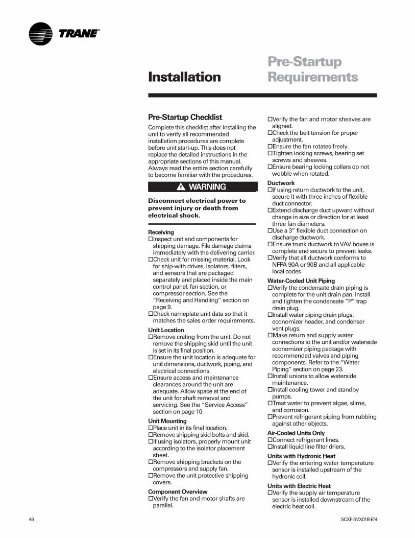
46 SCXF-SVX01B-EN
Pre-Startup Checklist
Complete this checklist after installing theunit to verify all recommendedinstallation procedures are completebefore unit start-up. This does notreplace the detailed instructions in theappropriate sections of this manual.Always read the entire section carefullyto become familiar with the procedures.
Disconnect electrical power toprevent injury or death fromelectrical shock.
Receiving�Inspect unit and components for
shipping damage. File damage claimsimmediately with the delivering carrier.
�Check unit for missing material. Lookfor ship-with drives, isolators, filters,and sensors that are packagedseparately and placed inside the maincontrol panel, fan section, orcompressor section. See the“Receiving and Handling” section onpage 9.
�Check nameplate unit data so that itmatches the sales order requirements.
Unit Location�Remove crating from the unit. Do not
remove the shipping skid until the unitis set in its final position.
�Ensure the unit location is adequate forunit dimensions, ductwork, piping, andelectrical connections.
�Ensure access and maintenanceclearances around the unit areadequate. Allow space at the end ofthe unit for shaft removal andservicing. See the “Service Access”section on page 10.
Unit Mounting�Place unit in its final location.�Remove shipping skid bolts and skid.�If using isolators, properly mount unit
according to the isolator placementsheet.
�Remove shipping brackets on thecompressors and supply fan.
�Remove the unit protective shippingcovers.
Component Overview�Verify the fan and motor shafts are
parallel.
Pre-StartupRequirements
�Verify the fan and motor sheaves arealigned.
�Check the belt tension for properadjustment.
�Ensure the fan rotates freely.�Tighten locking screws, bearing set
screws and sheaves.�Ensure bearing locking collars do not
wobble when rotated.
Ductwork�If using return ductwork to the unit,
secure it with three inches of flexibleduct connector.
�Extend discharge duct upward withoutchange in size or direction for at leastthree fan diameters.
�Use a 3” flexible duct connection ondischarge ductwork.
�Ensure trunk ductwork to VAV boxes iscomplete and secure to prevent leaks.
�Verify that all ductwork conforms toNFPA 90A or 90B and all applicablelocal codes
Water-Cooled Unit Piping�Verify the condensate drain piping is
complete for the unit drain pan. Installand tighten the condensate “P” trapdrain plug.
�Install water piping drain plugs,economizer header, and condenservent plugs.
�Make return and supply waterconnections to the unit and/or watersideeconomizer piping package withrecommended valves and pipingcomponents. Refer to the “WaterPiping” section on page 23.
�Install unions to allow watersidemaintenance.
�Install cooling tower and standbypumps.
�Treat water to prevent algae, slime,and corrosion.
�Prevent refrigerant piping from rubbingagainst other objects.
Air-Cooled Units Only�Connect refrigerant lines.�Install liquid line filter driers.
Units with Hydronic Heat�Verify the entering water temperature
sensor is installed upstream of thehydronic coil.
Units with Electric Heat�Verify the supply air temperature
sensor is installed downstream of theelectric heat coil.
����� WARNING!
Installation
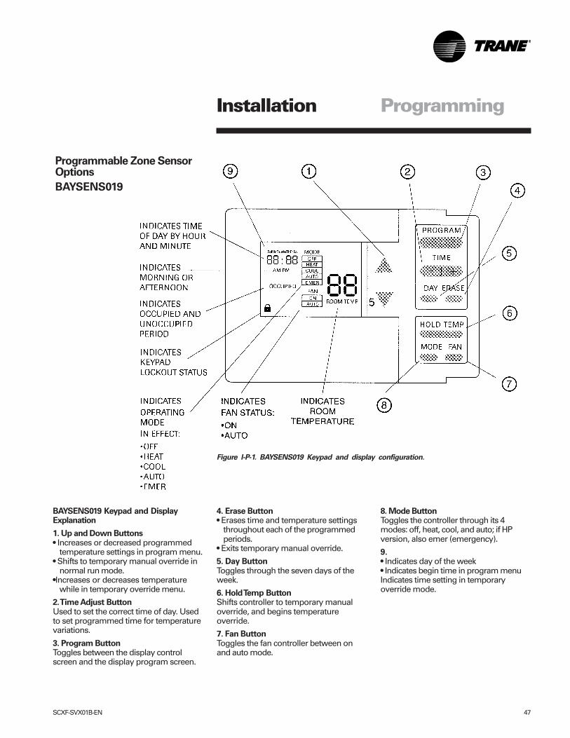
SCXF-SVX01B-EN 47
ProgrammingInstallation
Figure I-P-1. BAYSENS019 Keypad and display configuration.
BAYSENS019 Keypad and DisplayExplanation
1. Up and Down Buttons• Increases or decreased programmed
temperature settings in program menu.• Shifts to temporary manual override in
normal run mode.•Increases or decreases temperature
while in temporary override menu.
2. Time Adjust ButtonUsed to set the correct time of day. Usedto set programmed time for temperaturevariations.
3. Program ButtonToggles between the display controlscreen and the display program screen.
4. Erase Button• Erases time and temperature settings
throughout each of the programmedperiods.
• Exits temporary manual override.
5. Day ButtonToggles through the seven days of theweek.
6. Hold Temp ButtonShifts controller to temporary manualoverride, and begins temperatureoverride.
7. Fan ButtonToggles the fan controller between onand auto mode.
8. Mode ButtonToggles the controller through its 4modes: off, heat, cool, and auto; if HPversion, also emer (emergency).
9.• Indicates day of the week• Indicates begin time in program menuIndicates time setting in temporaryoverride mode.
Programmable Zone SensorOptions
BAYSENS019
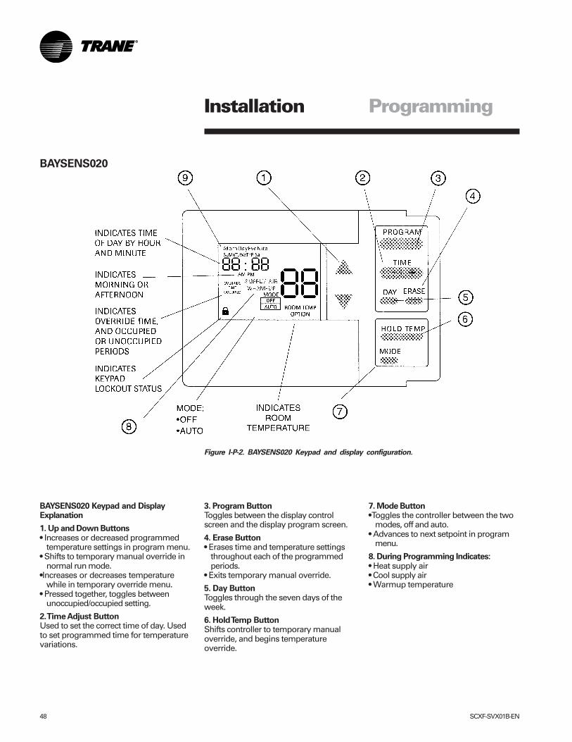
48 SCXF-SVX01B-EN
ProgrammingInstallation
Figure I-P-2. BAYSENS020 Keypad and display configuration.
BAYSENS020
BAYSENS020 Keypad and DisplayExplanation
1. Up and Down Buttons• Increases or decreased programmed
temperature settings in program menu.• Shifts to temporary manual override in
normal run mode.•Increases or decreases temperature
while in temporary override menu.• Pressed together, toggles between
unoccupied/occupied setting.
2. Time Adjust ButtonUsed to set the correct time of day. Usedto set programmed time for temperaturevariations.
3. Program ButtonToggles between the display controlscreen and the display program screen.
4. Erase Button• Erases time and temperature settings
throughout each of the programmedperiods.
• Exits temporary manual override.
5. Day ButtonToggles through the seven days of theweek.
6. Hold Temp ButtonShifts controller to temporary manualoverride, and begins temperatureoverride.
7. Mode Button• Toggles the controller between the two
modes, off and auto.• Advances to next setpoint in program
menu.
8. During Programming Indicates:• Heat supply air• Cool supply air• Warmup temperature
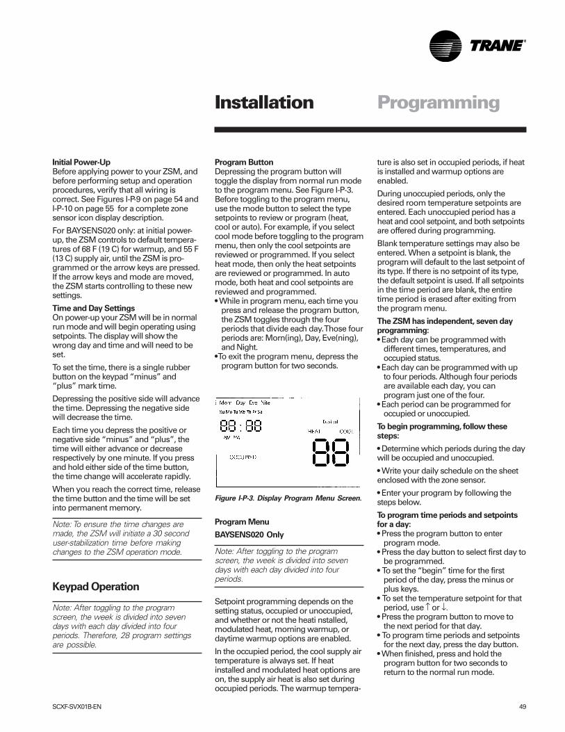
SCXF-SVX01B-EN 49
Program ButtonDepressing the program button willtoggle the display from normal run modeto the program menu. See Figure I-P-3.Before toggling to the program menu,use the mode button to select the typesetpoints to review or program (heat,cool or auto). For example, if you selectcool mode before toggling to the programmenu, then only the cool setpoints arereviewed or programmed. If you selectheat mode, then only the heat setpointsare reviewed or programmed. In automode, both heat and cool setpoints arereviewed and programmed.• While in program menu, each time you
press and release the program button,the ZSM toggles through the fourperiods that divide each day. Those fourperiods are: Morn(ing), Day, Eve(ning),and Night.
• To exit the program menu, depress theprogram button for two seconds.
Program Menu
BAYSENS020 Only
Note: After toggling to the programscreen, the week is divided into sevendays with each day divided into fourperiods.
Setpoint programming depends on thesetting status, occupied or unoccupied,and whether or not the heati nstalled,modulated heat, morning warmup, ordaytime warmup options are enabled.
In the occupied period, the cool supply airtemperature is always set. If heatinstalled and modulated heat options areon, the supply air heat is also set duringoccupied periods. The warmup tempera-
ProgrammingInstallation
Initial Power-UpBefore applying power to your ZSM, andbefore performing setup and operationprocedures, verify that all wiring iscorrect. See Figures I-P-9 on page 54 andI-P-10 on page 55 for a complete zonesensor icon display description.
For BAYSENS020 only: at initial power-up, the ZSM controls to default tempera-tures of 68 F (19 C) for warmup, and 55 F(13 C) supply air, until the ZSM is pro-grammed or the arrow keys are pressed.If the arrow keys and mode are moved,the ZSM starts controlling to these newsettings.
Time and Day SettingsOn power-up your ZSM will be in normalrun mode and will begin operating usingsetpoints. The display will show thewrong day and time and will need to beset.
To set the time, there is a single rubberbutton on the keypad “minus” and“plus” mark time.
Depressing the positive side will advancethe time. Depressing the negative sidewill decrease the time.
Each time you depress the positive ornegative side “minus” and “plus”, thetime will either advance or decreaserespectively by one minute. If you pressand hold either side of the time button,the time change will accelerate rapidly.
When you reach the correct time, releasethe time button and the time will be setinto permanent memory.
Note: To ensure the time changes aremade, the ZSM will initiate a 30 seconduser-stabilization time before makingchanges to the ZSM operation mode.
Keypad Operation
Note: After toggling to the programscreen, the week is divided into sevendays with each day divided into fourperiods. Therefore, 28 program settingsare possible.
ture is also set in occupied periods, if heatis installed and warmup options areenabled.
During unoccupied periods, only thedesired room temperature setpoints areentered. Each unoccupied period has aheat and cool setpoint, and both setpointsare offered during programming.
Blank temperature settings may also beentered. When a setpoint is blank, theprogram will default to the last setpoint ofits type. If there is no setpoint of its type,the default setpoint is used. If all setpointsin the time period are blank, the entiretime period is erased after exiting fromthe program menu.
The ZSM has independent, seven dayprogramming:• Each day can be programmed with
different times, temperatures, andoccupied status.
• Each day can be programmed with upto four periods. Although four periodsare available each day, you canprogram just one of the four.
• Each period can be programmed foroccupied or unoccupied.
To begin programming, follow thesesteps:
• Determine which periods during the daywill be occupied and unoccupied.
• Write your daily schedule on the sheetenclosed with the zone sensor.
• Enter your program by following thesteps below.
To program time periods and setpointsfor a day:• Press the program button to enter
program mode.• Press the day button to select first day to
be programmed.• To set the “begin” time for the first
period of the day, press the minus orplus keys.
• To set the temperature setpoint for thatperiod, use ↑ or ↓.
• Press the program button to move tothe next period for that day.
• To program time periods and setpointsfor the next day, press the day button.
• When finished, press and hold theprogram button for two seconds toreturn to the normal run mode.
Figure I-P-3. Display Program Menu Screen.
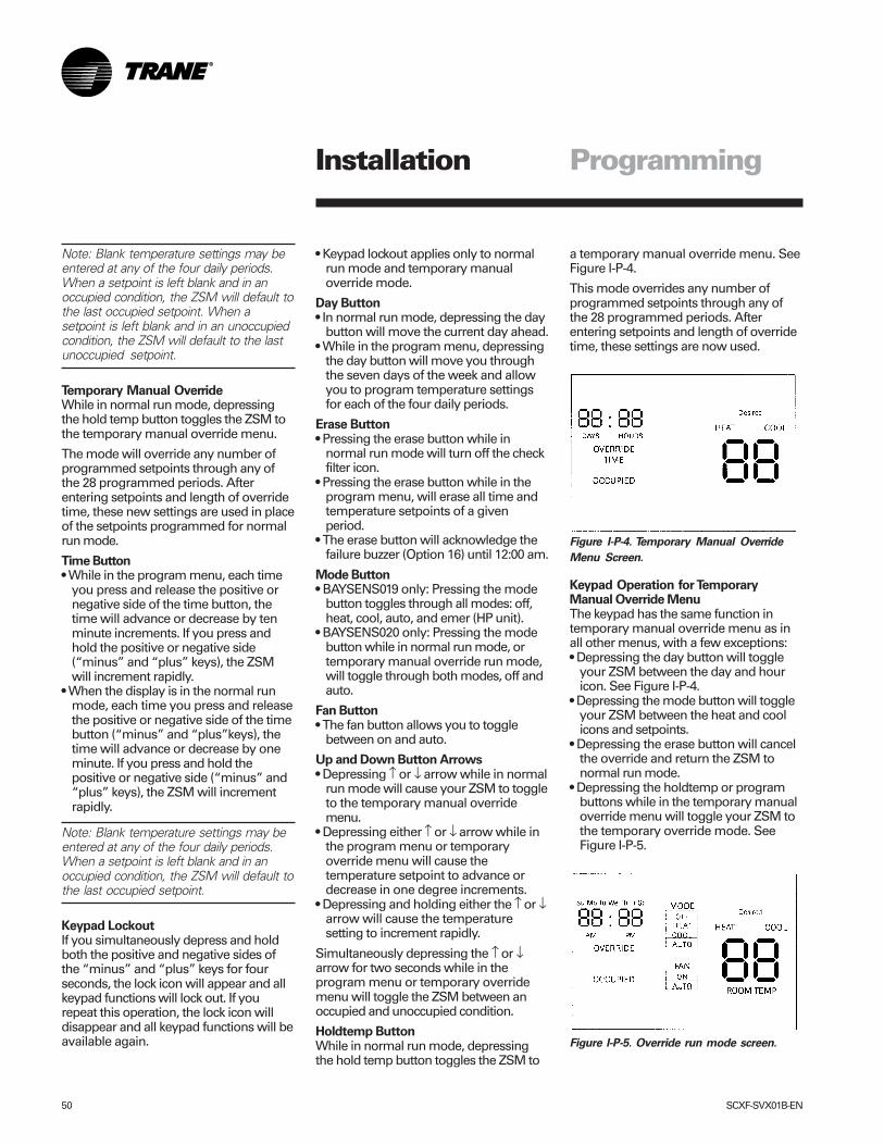
50 SCXF-SVX01B-EN
a temporary manual override menu. SeeFigure I-P-4.
This mode overrides any number ofprogrammed setpoints through any ofthe 28 programmed periods. Afterentering setpoints and length of overridetime, these settings are now used.
Keypad Operation for TemporaryManual Override MenuThe keypad has the same function intemporary manual override menu as inall other menus, with a few exceptions:• Depressing the day button will toggle
your ZSM between the day and houricon. See Figure I-P-4.
• Depressing the mode button will toggleyour ZSM between the heat and coolicons and setpoints.
• Depressing the erase button will cancelthe override and return the ZSM tonormal run mode.
• Depressing the holdtemp or programbuttons while in the temporary manualoverride menu will toggle your ZSM tothe temporary override mode. SeeFigure I-P-5.
ProgrammingInstallation
Note: Blank temperature settings may beentered at any of the four daily periods.When a setpoint is left blank and in anoccupied condition, the ZSM will default tothe last occupied setpoint. When asetpoint is left blank and in an unoccupiedcondition, the ZSM will default to the lastunoccupied setpoint.
Temporary Manual OverrideWhile in normal run mode, depressingthe hold temp button toggles the ZSM tothe temporary manual override menu.
The mode will override any number ofprogrammed setpoints through any ofthe 28 programmed periods. Afterentering setpoints and length of overridetime, these new settings are used in placeof the setpoints programmed for normalrun mode.
Time Button• While in the program menu, each time
you press and release the positive ornegative side of the time button, thetime will advance or decrease by tenminute increments. If you press andhold the positive or negative side(“minus” and “plus” keys), the ZSMwill increment rapidly.
• When the display is in the normal runmode, each time you press and releasethe positive or negative side of the timebutton (“minus” and “plus”keys), thetime will advance or decrease by oneminute. If you press and hold thepositive or negative side (“minus” and“plus” keys), the ZSM will incrementrapidly.
Note: Blank temperature settings may beentered at any of the four daily periods.When a setpoint is left blank and in anoccupied condition, the ZSM will default tothe last occupied setpoint.
Keypad LockoutIf you simultaneously depress and holdboth the positive and negative sides ofthe “minus” and “plus” keys for fourseconds, the lock icon will appear and allkeypad functions will lock out. If yourepeat this operation, the lock icon willdisappear and all keypad functions will beavailable again.
• Keypad lockout applies only to normalrun mode and temporary manualoverride mode.
Day Button• In normal run mode, depressing the day
button will move the current day ahead.• While in the program menu, depressing
the day button will move you throughthe seven days of the week and allowyou to program temperature settingsfor each of the four daily periods.
Erase Button• Pressing the erase button while in
normal run mode will turn off the checkfilter icon.
• Pressing the erase button while in theprogram menu, will erase all time andtemperature setpoints of a givenperiod.
• The erase button will acknowledge thefailure buzzer (Option 16) until 12:00 am.
Mode Button• BAYSENS019 only: Pressing the mode
button toggles through all modes: off,heat, cool, auto, and emer (HP unit).
• BAYSENS020 only: Pressing the modebutton while in normal run mode, ortemporary manual override run mode,will toggle through both modes, off andauto.
Fan Button• The fan button allows you to toggle
between on and auto.
Up and Down Button Arrows• Depressing ↑ or ↓ arrow while in normal
run mode will cause your ZSM to toggleto the temporary manual overridemenu.
• Depressing either ↑ or ↓ arrow while inthe program menu or temporaryoverride menu will cause thetemperature setpoint to advance ordecrease in one degree increments.
• Depressing and holding either the ↑ or ↓arrow will cause the temperaturesetting to increment rapidly.
Simultaneously depressing the ↑ or ↓arrow for two seconds while in theprogram menu or temporary overridemenu will toggle the ZSM between anoccupied and unoccupied condition.
Holdtemp ButtonWhile in normal run mode, depressingthe hold temp button toggles the ZSM to
Figure I-P-4. Temporary Manual Override
Menu Screen.
Figure I-P-5. Override run mode screen.
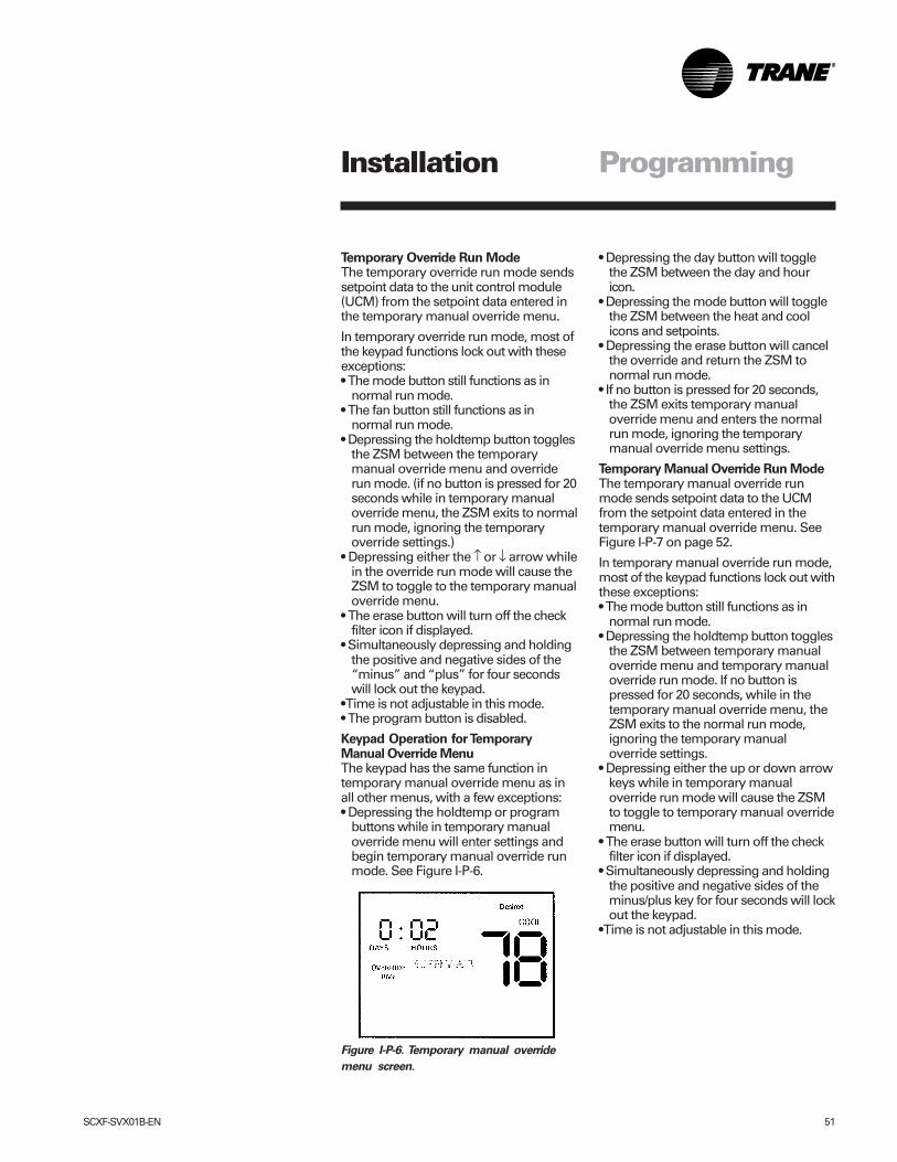
SCXF-SVX01B-EN 51
Temporary Override Run ModeThe temporary override run mode sendssetpoint data to the unit control module(UCM) from the setpoint data entered inthe temporary manual override menu.
In temporary override run mode, most ofthe keypad functions lock out with theseexceptions:• The mode button still functions as in
normal run mode.• The fan button still functions as in
normal run mode.• Depressing the holdtemp button toggles
the ZSM between the temporarymanual override menu and overriderun mode. (if no button is pressed for 20seconds while in temporary manualoverride menu, the ZSM exits to normalrun mode, ignoring the temporaryoverride settings.)
• Depressing either the ↑ or ↓ arrow whilein the override run mode will cause theZSM to toggle to the temporary manualoverride menu.
• The erase button will turn off the checkfilter icon if displayed.
• Simultaneously depressing and holdingthe positive and negative sides of the“minus” and “plus” for four secondswill lock out the keypad.
• Time is not adjustable in this mode.• The program button is disabled.
Keypad Operation for TemporaryManual Override MenuThe keypad has the same function intemporary manual override menu as inall other menus, with a few exceptions:• Depressing the holdtemp or program
buttons while in temporary manualoverride menu will enter settings andbegin temporary manual override runmode. See Figure I-P-6.
ProgrammingInstallation
• Depressing the day button will togglethe ZSM between the day and houricon.
• Depressing the mode button will togglethe ZSM between the heat and coolicons and setpoints.
• Depressing the erase button will cancelthe override and return the ZSM tonormal run mode.
• If no button is pressed for 20 seconds,the ZSM exits temporary manualoverride menu and enters the normalrun mode, ignoring the temporarymanual override menu settings.
Temporary Manual Override Run ModeThe temporary manual override runmode sends setpoint data to the UCMfrom the setpoint data entered in thetemporary manual override menu. SeeFigure I-P-7 on page 52.
In temporary manual override run mode,most of the keypad functions lock out withthese exceptions:• The mode button still functions as in
normal run mode.• Depressing the holdtemp button toggles
the ZSM between temporary manualoverride menu and temporary manualoverride run mode. If no button ispressed for 20 seconds, while in thetemporary manual override menu, theZSM exits to the normal run mode,ignoring the temporary manualoverride settings.
• Depressing either the up or down arrowkeys while in temporary manualoverride run mode will cause the ZSMto toggle to temporary manual overridemenu.
• The erase button will turn off the checkfilter icon if displayed.
• Simultaneously depressing and holdingthe positive and negative sides of theminus/plus key for four seconds will lockout the keypad.
• Time is not adjustable in this mode.
Figure I-P-6. Temporary manual override
menu screen.
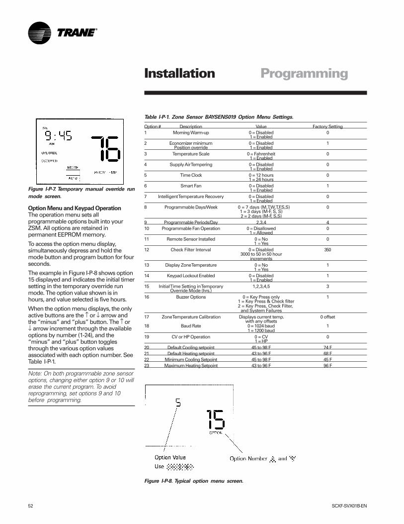
52 SCXF-SVX01B-EN
Table I-P-1. Zone Sensor BAYSENS019 Option Menu Settings.
Option # Description Value Factory Setting1 Morning Warm-up 0 = Disabled 0
1 = Enabled2 Economizer minimum 0 = Disabled 1
Position override 1 = Enabled3 Temperature Scale 0 = Fahrenheit 0
1 = Enabled4 Supply Air Tempering 0 = Disabled 0
1 = Enabled5 Time Clock 0 = 12 hours 0
1 = 24 hours6 Smart Fan 0 = Disabled 1
1 = Enabled7 Intelligent Temperature Recovery 0 = Disabled 0
1 = Enabled8 Programmable Days/Week 0 = 7 days (M,T,W,T,F,S,S) 0
1 = 3 days (M-F, S, S)2 = 2 days (M-F, S,S)
9 Programmable Periods/Day 2,3,4 410 Programmable Fan Operation 0 = Disallowed 0
1 = Allowed11 Remote Sensor Installed 0 = No 0
1 = Yes12 Check Filter Interval 0 = Disabled 350
3000 to 50 in 50 hourincrements
13 Display Zone Temperature 0 = No 11 = Yes
14 Keypad Lockout Enabled 0 = Disabled 11 = Enabled
15 Initial Time Setting in Temporary 1,2,3,4,5 3Override Mode (hrs.)
16 Buzzer Options 0 = Key Press only 11 = Key Press & Check filter2 = Key Press, Check Filter,
and System Failures17 Zone Temperature Calibration Displays current temp. 0 offset
with any offsets18 Baud Rate 0 = 1024 baud 1
1 = 1200 baud19 CV or HP Operation 0 = CV 0
1 = HP20 Default Cooling setpoint 45 to 98 F 74 F21 Default Heating setpoint 43 to 96 F 68 F22 Minimum Cooling Setpoint 45 to 98 F 45 F23 Maximum Heating Setpoint 43 to 96 F 96 F
ProgrammingInstallation
Figure I-P-8. Typical option menu screen.
Option Menu and Keypad OperationThe operation menu sets allprogrammable options built into yourZSM. All options are retained inpermanent EEPROM memory.
To access the option menu display,simultaneously depress and hold themode button and program button for fourseconds.
The example in Figure I-P-8 shows option15 displayed and indicates the initial timersetting in the temporary override runmode. The option value shown is inhours, and value selected is five hours.
When the option menu displays, the onlyactive buttons are the ↑ or ↓ arrow andthe “minus” and “plus” button. The ↑ or↓ arrow increment through the availableoptions by number (1-24), and the“minus” and “plus” button togglesthrough the various option valuesassociated with each option number. SeeTable I-P-1.
Note: On both programmable zone sensoroptions, changing either option 9 or 10 willerase the current program. To avoidreprogramming, set options 9 and 10before programming.
Figure I-P-7. Temporary manual override run
mode screen.
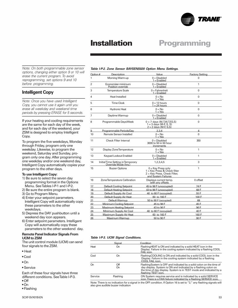
SCXF-SVX01B-EN 53
ProgrammingInstallation
Table I-P-2. Zone Sensor BAYSENS020 Option Menu Settings.
Option # Description Value Factory Setting1 Morning Warm-up 0 = Disabled 0
1 = Enabled2 Economizer minimum 0 = Disabled 1
Position override 1 = Enabled3 Temperature Scale 0 = Fahrenheit 0
1 = Enabled4 Heat Installed 0 = No 0
1 = Yes5 Time Clock 0 = 12 hours 0
1 = 24 hours6 Hydronic Heat 0 = No 0
1 = Yes7 Daytime Warmup 0 = Disabled 0
1 = Enabled8 Programmable Days/Week 0 = 7 days (M,T,W,T,F,S,S) 0
1 = 3 days (M-F, S, S)2 = 2 days (M-F, S,S)
9 Programmable Periods/Day 2,3,4 410 Remote Sensor Installed 0 = No 0
1 = Yes11 Check Filter Interval 0 = Disabled 350
3000 to 50 in 50 hourincrements
12 Display Zone Temperature 0 = No 11 = Yes
13 Keypad Lockout Enabled 0 = Disabled 11 = Enabled
14 Initial Time Setting in Temporary 1,2,3,4,5 3Override Mode (hrs.)
15 Buzzer Options 0 = Key Press only 11 = Key Press & Check filter2 = Key Press, Check Filter,
and System Failures16 Zone Temperature Calibration Displays current temp. 0 offset
with any offsets17 Default Cooling Setpoint 45 to 98 F (unoccupied) 74 F18 Default Heating Setpoint 43 to 96 F (unoccupied) 68 F19 Default Supply Air Cool 40 to 80 F (occupied) 55 F20 Default Supply Air Heat 60 to 160 F 100 F21 Default Warmup 50 to 90 F (occupied) 6822 Minimum Cooling Setpoint 45 to 98 F 45 F23 Maximum Heating Setpoint 43 to 96 F 96 F24 Minimum Supply Air Cool 40 to 80 F (occupied) 40 F25 Maximum Supply Air Heat 60 to 160 F 160 F26 Maximum Warmup 50 to 90 F 90 F
Note: On both programmable zone sensoroptions, changing either option 9 or 10 willerase the current program. To avoidreprogramming, set options 9 and 10before programming.
Intelligent Copy
Note: Once you have used IntelligentCopy, you cannot use it again until youerase all weekday and weekend timeperiods by pressing ERASE for 5 seconds.
If your heating and cooling requirementsare the same for each day of the week,and for each day of the weekend, yourZSM is designed to employ IntelligentCopy.
To program the five weekdays, Mondaythrough Friday, program only oneweekday. Likewise, to program theweekend, Saturday and Sunday, pro-gram only one day. After programmingone weekday and/or one weekend day,Intelligent Copy automatically copies yourprogram to the other days.
To use Intelligent Copy:1) Be sure to select the seven day
programming format in the OptionsMenu. See Tables I-P-1 and I-P-2.
2) Be sure the entire program is blank.3) Go to Program Menu.4) Enter your setpoint parameters.
Intelligent Copy will automatically copythese parameters to the otherweekdays.
5) Depress the DAY pushbutton until aweekend day icon appears.
6) Enter setpoint parameters. IntelligentCopy will automatically copy theseparameters to the other weekend day.
Remote Panel Indicator Signals FromUCM to ZSMThe unit control module (UCM) can sendfour signals to the ZSM.
• Heat
• Cool
• On
• Service
Each of these four signals have threedifferent conditions. See Table I-P-3.• Off• On• Flashing
Table I-P-3. UCM Signal Conditions.
Signal ConditionHeat On FlashingHEAT is ON and indicated by a solid HEAT icon in the
Display. Failure in the cooling system indicated by a flashing COOL FAIL icon.
Cool On FlashingCOOLING is ON and indicated by a solid COOL icon in the Display. Failure in the cooling system indicated by a flashing COOL FAIL icon.
On Off FlashingSystem is OFF and indicated by a solid colon on the time ofOn day display. System is ON and indicated by a flashing colon on
the time of day display. System is in TEST mode and indicated by a flashing TEST icon.
Service Flashing ON System requires service and is indicated by a solid SERVICE icon. There is a FAN failure indicated by a flashing SERVICE icon.
Note: There is no indication for a signal in the OFF condition. If Option 16 is set to “2,” any flashing signals willalso give audible buzzer indication
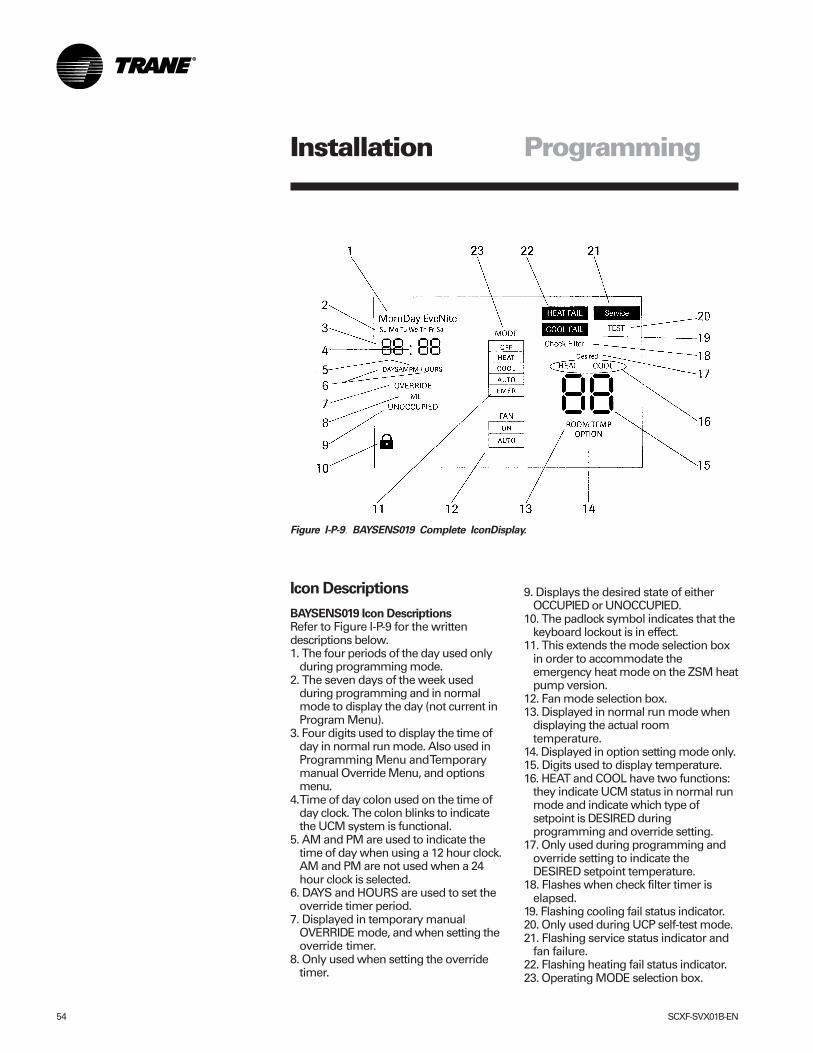
54 SCXF-SVX01B-EN
ProgrammingInstallation
Icon Descriptions
BAYSENS019 Icon DescriptionsRefer to Figure I-P-9 for the writtendescriptions below.1. The four periods of the day used only
during programming mode.2. The seven days of the week used
during programming and in normalmode to display the day (not current inProgram Menu).
3. Four digits used to display the time ofday in normal run mode. Also used inProgramming Menu and Temporarymanual Override Menu, and optionsmenu.
4. Time of day colon used on the time ofday clock. The colon blinks to indicatethe UCM system is functional.
5. AM and PM are used to indicate thetime of day when using a 12 hour clock.AM and PM are not used when a 24hour clock is selected.
6. DAYS and HOURS are used to set theoverride timer period.
7. Displayed in temporary manualOVERRIDE mode, and when setting theoverride timer.
8. Only used when setting the overridetimer.
Figure I-P-9. BAYSENS019 Complete IconDisplay.
9. Displays the desired state of eitherOCCUPIED or UNOCCUPIED.
10. The padlock symbol indicates that thekeyboard lockout is in effect.
11. This extends the mode selection boxin order to accommodate theemergency heat mode on the ZSM heatpump version.
12. Fan mode selection box.13. Displayed in normal run mode when
displaying the actual roomtemperature.
14. Displayed in option setting mode only.15. Digits used to display temperature.16. HEAT and COOL have two functions:
they indicate UCM status in normal runmode and indicate which type ofsetpoint is DESIRED duringprogramming and override setting.
17. Only used during programming andoverride setting to indicate theDESIRED setpoint temperature.
18. Flashes when check filter timer iselapsed.
19. Flashing cooling fail status indicator.20. Only used during UCP self-test mode.21. Flashing service status indicator and
fan failure.22. Flashing heating fail status indicator.23. Operating MODE selection box.
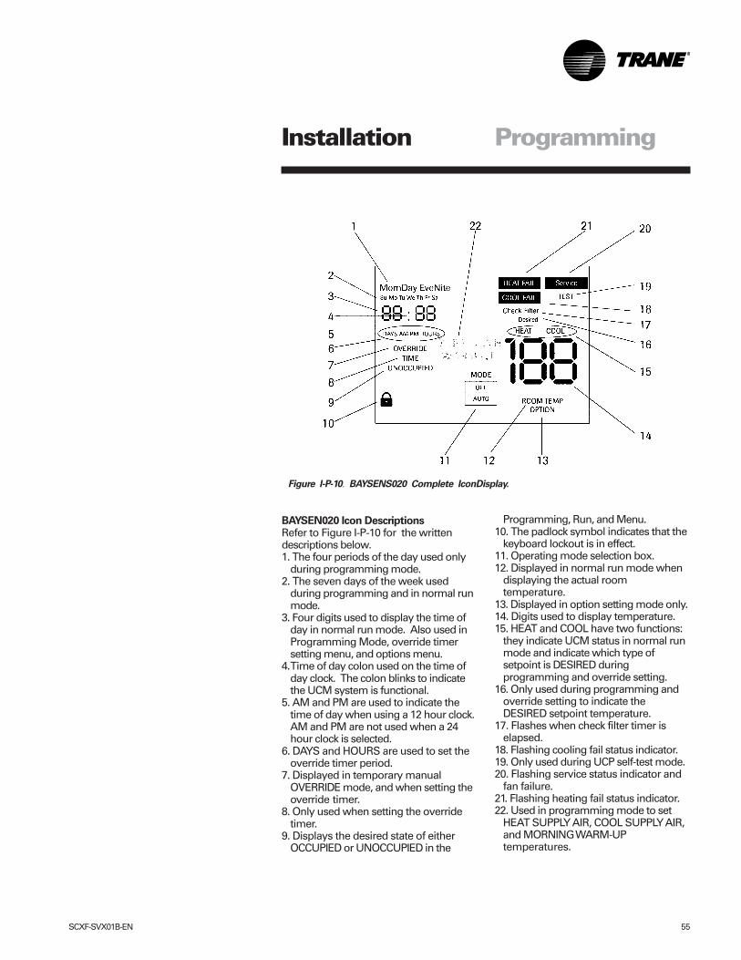
SCXF-SVX01B-EN 55
ProgrammingInstallation
Figure I-P-10. BAYSENS020 Complete IconDisplay.
BAYSEN020 Icon DescriptionsRefer to Figure I-P-10 for the writtendescriptions below.1. The four periods of the day used only
during programming mode.2. The seven days of the week used
during programming and in normal runmode.
3. Four digits used to display the time ofday in normal run mode. Also used inProgramming Mode, override timersetting menu, and options menu.
4. Time of day colon used on the time ofday clock. The colon blinks to indicatethe UCM system is functional.
5. AM and PM are used to indicate thetime of day when using a 12 hour clock.AM and PM are not used when a 24hour clock is selected.
6. DAYS and HOURS are used to set theoverride timer period.
7. Displayed in temporary manualOVERRIDE mode, and when setting theoverride timer.
8. Only used when setting the overridetimer.
9. Displays the desired state of eitherOCCUPIED or UNOCCUPIED in the
Programming, Run, and Menu.10. The padlock symbol indicates that the
keyboard lockout is in effect.11. Operating mode selection box.12. Displayed in normal run mode when
displaying the actual roomtemperature.
13. Displayed in option setting mode only.14. Digits used to display temperature.15. HEAT and COOL have two functions:
they indicate UCM status in normal runmode and indicate which type ofsetpoint is DESIRED duringprogramming and override setting.
16. Only used during programming andoverride setting to indicate theDESIRED setpoint temperature.
17. Flashes when check filter timer iselapsed.
18. Flashing cooling fail status indicator.19. Only used during UCP self-test mode.20. Flashing service status indicator and
fan failure.21. Flashing heating fail status indicator.22. Used in programming mode to set
HEAT SUPPLY AIR, COOL SUPPLY AIR,and MORNING WARM-UPtemperatures.
56 SCXF-SVX01B-EN
Programming the Time ClockOption
Setting the TimeImportant: Depress reset key beforebeginning to set time and program.1. Select military (24:00 hr.) or AM/PM
(12:00 hr.) time mode by depressingand holding the “h” key while pressing“+ 1h” key to toggle between militaryand AM/PM. (AM appears in the displaywhen in AM/PM mode.)
2. Press and hold down “�” key.3. If setting the time when daylight
savings time is in effect, press “+ 1h”key once (+ 1h will appear in display).
4. Set hour with “h” key. If AM or PMdoes not appear in display, the unit is inmilitary time. See note above tochange display.
5. Set minutes with “m” key.6. Press “Day” key repeatedly to the day
of the week. (1 is Monday, 7 is Sunday)7. Release “�” key, colon will begin
flashing.
Note: If keys h + or m + are kept de-pressed for longer than 2 seconds, arapid advance of figures will result.
The “Digi 20” electronic time switch isfreely programmable for each day of theweek in one minute increments. For easyand quick programming, the following 4block programs are available:• Monday through Sunday• Monday through Saturday• Monday through Friday• Saturday and Sunday
ProgrammingFollow the instructions below forprogramming the time clock.1. Press “Prog.” key. 1234567 AM—:—
will appear in display. (Pressing “Prog.”key again, display will show thenumber of free programs “Fr 20”).Press again to RETURN to 1st program.
2. Press “�” key, “�” ON symbol willappear. Pressing the key again willtoggle to OFF “�”. Select ON or OFFfor the program.
3. Press “h+” to select hour for switchingtime.
4. Press “m+” to select minute forswitching time.
5. If the program is to occur every day ofthe week, (24 hour time control) ignore
“Day” key and press “Prog.” key toadvance to program.
6. For 7 day time control, press “Day”key. 1 2 3 4 5 6 (Monday throughSaturday) block of days appears indisplay. Pressing “Day” key again, 1 2 34 5 (Monday through Friday) appears indisplay. Repeated presses will cyclethrough all days of the week and backto 1 through 7 (Monday throughSunday). Select day or block of days desired.
7. Press “Prog.” key and repeat steps 2through 6a to enter additionalprograms of ON and OFF times. (Notethat more than one OFF time may beprogrammed, enabling automaticcontrol or manual overrides.)
8. Press “�” key to enter run mode.
To review and change programs:1. To review a program at any time, press
“Prog.” key. Programs display in thesequence they were entered withrepeated presses of “Prog.” key.
2. To change a program, select thatprogram as outlined in step 1. Enter thetime of day and days of week just as inthe programming steps above. The oldprogram is overwritten with the newselections. Press “Prog.” to store thenew program.
3. To delete an individual program, selectthe program as in step 1 and press “h”and “m” keys until “—:—” appears inthe display. Press either “Prog.” or “¹”key until “—:—” flashes. The programis deleted after a few seconds.
Manual OverrideWhile in the “run” mode (“�” symbol isdisplayed), pressing the “�” key willreverse the load status (switch load off ifit is on, or switch it on if it is off). A handsymbol appears in the display to indicatethe override is active. At the nextscheduled switching time, automatic timecontrol resumes, eliminating the override.
Pressing the “�” key a second time“[�]” appears in the display indicatingthe load is permanently on.
Pressing the “�” key a third time “[�]”appears in the display indicating the load
is permanently off.
Pressing the “�” key a fourth timereturns to automatic, “�” appears in thedisplay.
All days shown in the respective blockswill switch on (or off) at the selected hourand minute.
ProgrammingInstallation
SCXF-SVX01B-EN 57
Unit Start-Up Procedures
1. Check all electrical connections fortightness.
2. For water-cooled units: gain access tothe liquid line service valves in the unit’sleft lower section.
Note: Verify the liquid line service valve isopen at unit start-up. Each compressorsuction line contains a low pressuresensor that will shut the compressor downin low pressure situations. See Table O-SO-2 on page 80.
Never manually or automaticallypump down below 7 psig. Thiswill cause the compressor tooperate in a vacuum and causecompressor damage.
1. Be sure all system components areproperly set and installed.
2. Inspect all ductwork and ductconnections.
3. Remove compressor and fanassembly tie down bolts. However, on20-38 ton units, do not remove the fanassembly shipping blocks and tie downbolts if the fan speed is 750 rpm or less.
To start the unit, complete the followinglist in order:1. Apply power to the unit. Close the unit
disconnect switch option.2. Make sure that the liquid line service
valves are open on water cooled units.3. Adjust setpoints at the HI.
See the IntelliPak ® Self-ContainedProgramming Guide, PKG-SVP01B-EN,for available unit operating setpoints.Refer to the job specifications for propersetpoints.
Note: A sufficient cooling load must bevisible to refrigerant circuit controls for themechanical refrigeration to operate. Ifnecessary, temporarily reduce the dis-charge air setpoint to verify the refrigera-tion cycle operation.
1. Ensure the fan rotation is in thedirection of the arrow on the fanhousing. If rotation is incorrect, firstverify the incoming power phasing iscorrect. If it is correct, switch wires onthe fan contact so the fan is properlyphased.
2. Check the fan belt condition andtension. Adjust the tension if belts arefloppy or squeal continually. Replaceworn or fraying belts in matched sets.
3. Check voltage at all compressorterminals. Actual voltage should bewithin 10 percent of nameplate voltage.
4. Check voltage imbalance from thesethree voltage readings, at eachcompressor. Maximum allowablevoltage imbalance, phase to phase, is2%.
5. Check amp draw at compressorterminals. RLA and LRA is on the unitnameplate.
6. Measure amp draw at evaporator fanmotor terminals. FLA data is on themotor nameplate.
7. After the system has stabilized (15 to30 minutes), check and recordoperating pressures and temperaturesfor all circuits.
When checking the operating pressuresand conditions, establish nominalconditions for consistent measurementsas follows:•Leaving air greater than 60 F•Entering air temperature between 70
and 90 F•Entering water temperature greater
than 60 F•Inlet guide vanes at least halfway open
With all compressors running at full load:1. Compute superheat from the suction
line pressure and temperature at thecompressor on each circuit. Adjust thethermal expansion valve settings ifnecessary. Superheat should bebetween 12 and 17 F.
2. Inspect refrigerant flow in the liquid linesight glass. Flow should be smooth andeven, with no bubbles once the systemhas stabilized.
Normal start-up can occur provided thatTracer Summit® is not controlling themodule outputs or the generic BAS is notkeeping the unit off.
To ensure that Tracer Summit® has noaffect on unit operation, remove Tracer®
wiring and make required changes tosetpoint and sensor sources. See theIntelliPak ® Self-Contained ProgrammingGuide, PKG-SVP01B-EN, for moreinformation.
Unit Start-Up
Reference the IntelliPak ® Self-ContainedProgramming Guide, PKG-SVP01B-EN,for unit operating instructions. A copyships with each unit.
For units with the VFD option, referenceInstruction Bulletin, Altivar 58 AdjustableDrive Controllers and/or InstallationGuide, Type H Controllers KeypadDisplay. A copy ships with each VFD.����� CAUTION!
Start-UpInstallation
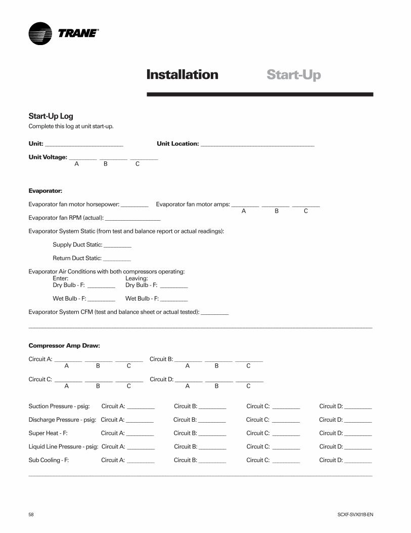
58 SCXF-SVX01B-EN
Installation
Start-Up Log
Complete this log at unit start-up.
Unit: ____________________________ Unit Location: _________________________________________
Unit Voltage: __________ __________ __________ A B C
Evaporator:
Evaporator fan motor horsepower: __________ Evaporator fan motor amps: __________ __________ __________ A B C
Evaporator fan RPM (actual): ____________________
Evaporator System Static (from test and balance report or actual readings):
Supply Duct Static: __________
Return Duct Static: __________
Evaporator Air Conditions with both compressors operating:Enter: Leaving:Dry Bulb - F: __________ Dry Bulb - F: __________
Wet Bulb - F: __________ Wet Bulb - F: __________
Evaporator System CFM (test and balance sheet or actual tested): __________
___________________________________________________________________________________________________________________________
Compressor Amp Draw:
Circuit A: __________ __________ __________ Circuit B: __________ __________ __________ A B C A B C
Circuit C: __________ __________ __________ Circuit D: __________ __________ __________ A B C A B C
Suction Pressure - psig: Circuit A: __________ Circuit B: __________ Circuit C: __________ Circuit D: __________
Discharge Pressure - psig: Circuit A: __________ Circuit B: __________ Circuit C: __________ Circuit D: __________
Super Heat - F: Circuit A: __________ Circuit B: __________ Circuit C: __________ Circuit D: __________
Liquid Line Pressure - psig: Circuit A: __________ Circuit B: __________ Circuit C: __________ Circuit D: __________
Sub Cooling - F: Circuit A: __________ Circuit B: __________ Circuit C: __________ Circuit D: __________
___________________________________________________________________________________________________________________________
Start-Up
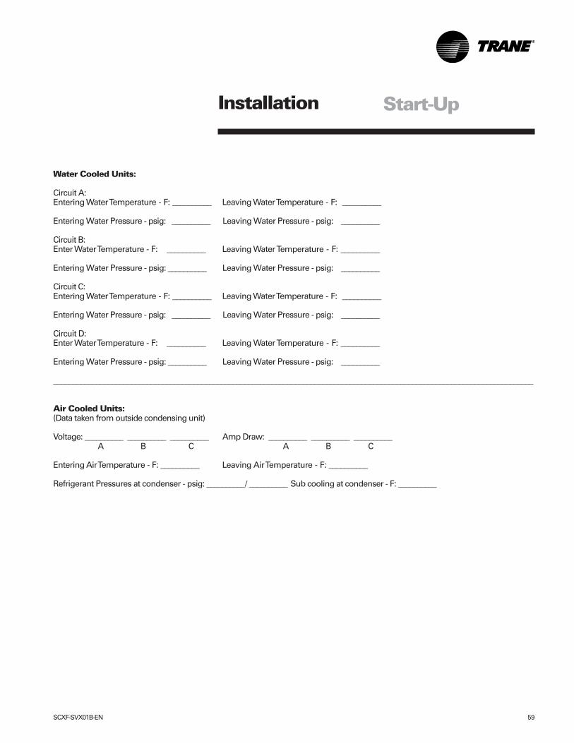
SCXF-SVX01B-EN 59
Installation Start-Up
Water Cooled Units:
Circuit A:Entering Water Temperature - F: __________ Leaving Water Temperature - F: __________
Entering Water Pressure - psig: __________ Leaving Water Pressure - psig: __________
Circuit B:Enter Water Temperature - F: __________ Leaving Water Temperature - F: __________
Entering Water Pressure - psig: __________ Leaving Water Pressure - psig: __________
Circuit C:Entering Water Temperature - F: __________ Leaving Water Temperature - F: __________
Entering Water Pressure - psig: __________ Leaving Water Pressure - psig: __________
Circuit D:Enter Water Temperature - F: __________ Leaving Water Temperature - F: __________
Entering Water Pressure - psig: __________ Leaving Water Pressure - psig: __________
___________________________________________________________________________________________________________________________
Air Cooled Units:(Data taken from outside condensing unit)
Voltage: __________ __________ __________ Amp Draw: __________ __________ __________ A B C A B C
Entering Air Temperature - F: __________ Leaving Air Temperature - F: __________
Refrigerant Pressures at condenser - psig: __________/ __________ Sub cooling at condenser - F: __________
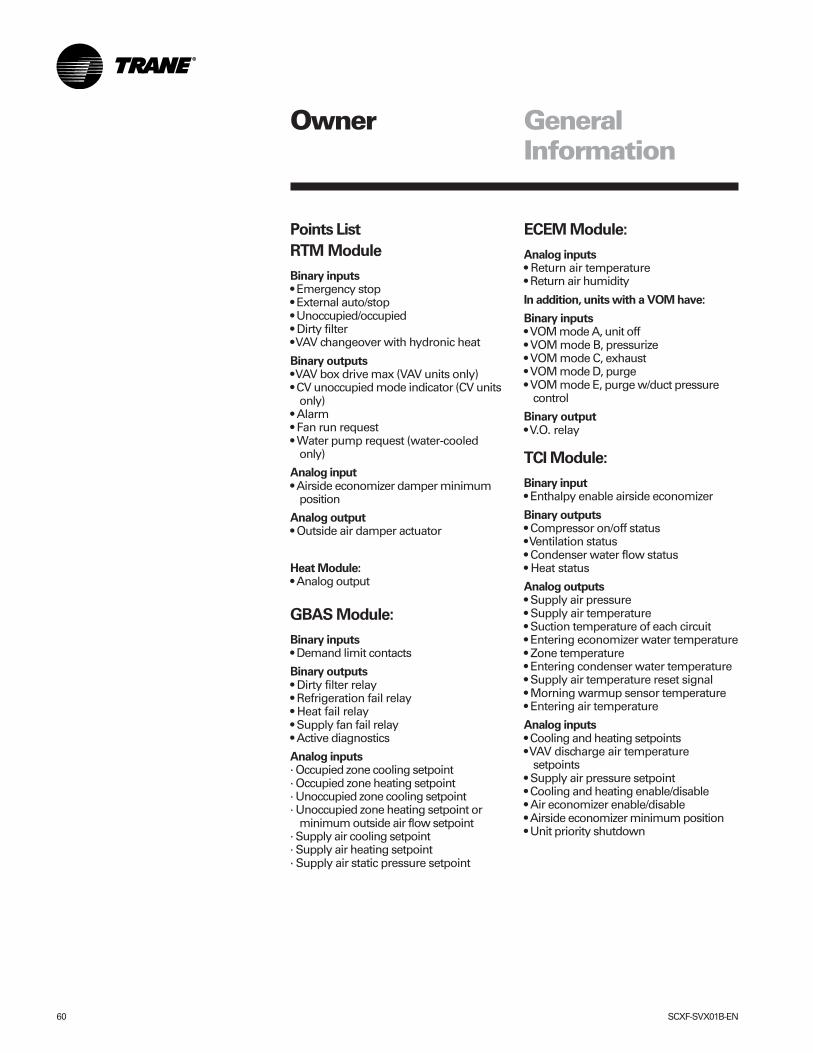
60 SCXF-SVX01B-EN
Owner GeneralInformation
Points List
RTM Module
Binary inputs• Emergency stop• External auto/stop• Unoccupied/occupied• Dirty filter• VAV changeover with hydronic heat
Binary outputs• VAV box drive max (VAV units only)• CV unoccupied mode indicator (CV units
only)• Alarm• Fan run request• Water pump request (water-cooled
only)
Analog input• Airside economizer damper minimum
position
Analog output• Outside air damper actuator
Heat Module:• Analog output
GBAS Module:
Binary inputs• Demand limit contacts
Binary outputs• Dirty filter relay• Refrigeration fail relay• Heat fail relay• Supply fan fail relay• Active diagnostics
Analog inputs· Occupied zone cooling setpoint· Occupied zone heating setpoint· Unoccupied zone cooling setpoint· Unoccupied zone heating setpoint or
minimum outside air flow setpoint· Supply air cooling setpoint· Supply air heating setpoint· Supply air static pressure setpoint
ECEM Module:
Analog inputs• Return air temperature• Return air humidity
In addition, units with a VOM have:
Binary inputs• VOM mode A, unit off• VOM mode B, pressurize• VOM mode C, exhaust• VOM mode D, purge• VOM mode E, purge w/duct pressure
control
Binary output• V.O. relay
TCI Module:
Binary input• Enthalpy enable airside economizer
Binary outputs• Compressor on/off status• Ventilation status• Condenser water flow status• Heat status
Analog outputs• Supply air pressure• Supply air temperature• Suction temperature of each circuit• Entering economizer water temperature• Zone temperature• Entering condenser water temperature• Supply air temperature reset signal• Morning warmup sensor temperature• Entering air temperature
Analog inputs• Cooling and heating setpoints• VAV discharge air temperature
setpoints• Supply air pressure setpoint• Cooling and heating enable/disable• Air economizer enable/disable• Airside economizer minimum position• Unit priority shutdown
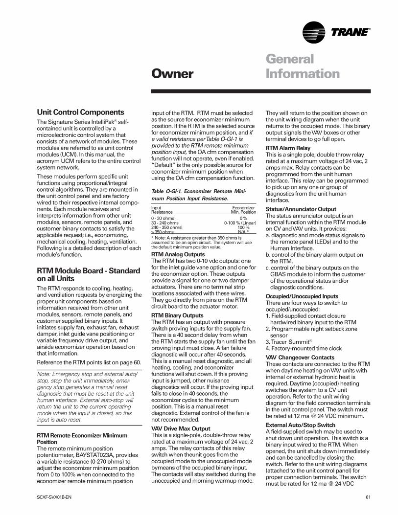
SCXF-SVX01B-EN 61
Unit Control Components
The Signature Series IntelliPak® self-contained unit is controlled by amicroelectronic control system thatconsists of a network of modules. Thesemodules are referred to as unit controlmodules (UCM). In this manual, theacronym UCM refers to the entire controlsystem network.
These modules perform specific unitfunctions using proportional/integralcontrol algorithms. They are mounted inthe unit control panel and are factorywired to their respective internal compo-nents. Each module receives andinterprets information from other unitmodules, sensors, remote panels, andcustomer binary contacts to satisfy theapplicable request; i.e., economizing,mechanical cooling, heating, ventilation.Following is a detailed description of eachmodule’s function.
RTM Module Board - Standardon all Units
The RTM responds to cooling, heating,and ventilation requests by energizing theproper unit components based oninformation received from other unitmodules, sensors, remote panels, andcustomer supplied binary inputs. Itinitiates supply fan, exhaust fan, exhaustdamper, inlet guide vane positioning orvariable frequency drive output, andairside economizer operation based onthat information.
Reference the RTM points list on page 60.
Note: Emergency stop and external auto/stop, stop the unit immediately, emer-gency stop generates a manual resetdiagnostic that must be reset at the unithuman interface. External auto-stop willreturn the unit to the current operatingmode when the input is closed, so thisinput is auto reset.
RTM Remote Economizer MinimumPositionThe remote minimum positionpotentiometer, BAYSTAT023A, providesa variable resistance (0-270 ohms) toadjust the economizer minimum positionfrom 0 to 100% when connected to theeconomizer remote minimum position
input of the RTM. RTM must be selectedas the source for economizer minimumposition. If the RTM is the selected sourcefor economizer minimum position, and ifa valid resistance per Table O-GI-1 isprovided to the RTM remote minimumposition input, the OA cfm compensationfunction will not operate, even if enabled.“Default” is the only possible source foreconomizer minimum position whenusing the OA cfm compensation function.
Table O-GI-1. Economizer Remote Mini-
mum Position Input Resistance.
Input EconomizerResistance Min. Position0 - 30 ohms 0 %30 - 240 ohms 0-100 % (Linear)240 - 350 ohmsI 100 %> 350 ohms N/A ** Note: A resistance greater than 350 ohms isassumed to be an open circuit. The system will usethe default minimum position value.
RTM Analog OutputsThe RTM has two 0-10 vdc outputs: onefor the inlet guide vane option and one forthe economizer option. These outputsprovide a signal for one or two damperactuators. There are no terminal striplocations associated with these wires.They go directly from pins on the RTMcircuit board to the actuator motor.
RTM Binary OutputsThe RTM has an output with pressureswitch proving inputs for the supply fan.There is a 40 second delay from whenthe RTM starts the supply fan until the fanproving input must close. A fan failurediagnostic will occur after 40 seconds.This is a manual reset diagnostic, and allheating, cooling, and economizerfunctions will shut down. If this provinginput is jumped, other nuisancediagnostics will occur. If the proving inputfails to close in 40 seconds, theeconomizer cycles to the minimumposition. This is a manual resetdiagnostic. External control of the fan isnot recommended.
VAV Drive Max OutputThis is a signle-pole, double-throw relayrated at a maximum voltage of 24 vac, 2amps. The relay contacts of this relayswitch when theunit goes from theoccupied mode to the unoccupied modebymeans of the occupied binary input.The contacts will stay switched during theunoccupied and morning warmup mode.
They will return to the position shown onthe unit wiring diagram when the unitreturns to the occupied mode. This binaryoutput signals the VAV boxes or otherterminal devices to go full open.
RTM Alarm RelayThis is a single pole, double throw relayrated at a maximum voltage of 24 vac, 2amps max. Relay contacts can beprogrammed from the unit humaninterface. This relay can be programmedto pick up on any one or group ofdiagnostics from the unit humaninterface.
Status/Annunciator OutputThe status annunciator output is aninternal function within the RTM moduleon CV and VAV units. It provides:a. diagnostic and mode status signals to
the remote panel (LEDs) and to theHuman Interface.
b. control of the binary alarm output onthe RTM.
c. control of the binary outputs on theGBAS module to inform the customerof the operational status and/ordiagnostic conditions.
Occupied/Unoccupied InputsThere are four ways to switch tooccupied/unoccupied:1. Field-supplied contact closure
hardwired binary input to the RTM2. Programmable night setback zone
sensor3. Tracer Summit®
4. Factory-mounted time clock
VAV Changeover ContactsThese contacts are connected to the RTMwhen daytime heating on VAV units withinternal or external hydronic heat isrequired. Daytime (occupied) heatingswitches the system to a CV unitoperation. Refer to the unit wiringdiagram for the field connection terminalsin the unit control panel. The switch mustbe rated at 12 ma @ 24 VDC minimum.
External Auto/Stop SwitchA field-supplied switch may be used toshut down unit operation. This switch is abinary input wired to the RTM. Whenopened, the unit shuts down immediatelyand can be cancelled by closing theswitch. Refer to the unit wiring diagrams(attached to the unit control panel) forproper connection terminals. The switchmust be rated for 12 ma @ 24 VDC
OwnerGeneralInformation
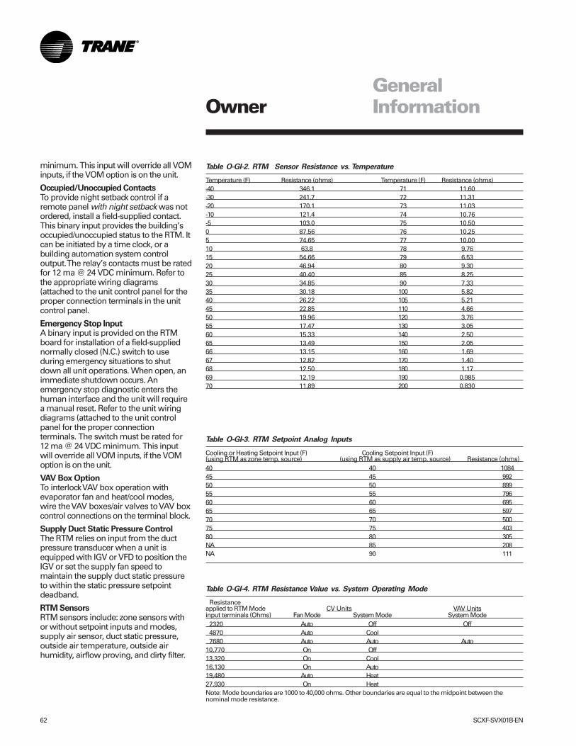
62 SCXF-SVX01B-EN
Table O-GI-2. RTM Sensor Resistance vs. Temperature
Temperature (F) Resistance (ohms) Temperature (F) Resistance (ohms)-40 346.1 71 11.60-30 241.7 72 11.31-20 170.1 73 11.03-10 121.4 74 10.76-5 103.0 75 10.500 87.56 76 10.255 74.65 77 10.0010 63.8 78 9.7615 54.66 79 6.5320 46.94 80 9.3025 40.40 85 8.2530 34.85 90 7.3335 30.18 100 5.8240 26.22 105 5.2145 22.85 110 4.6650 19.96 120 3.7655 17.47 130 3.0560 15.33 140 2.5065 13.49 150 2.0566 13.15 160 1.6967 12.82 170 1.4068 12.50 180 1.1769 12.19 190 0.98570 11.89 200 0.830
OwnerGeneralInformation
Table O-GI-4. RTM Resistance Value vs. System Operating Mode
Resistanceapplied to RTM Mode CV Units VAV Unitsinput terminals (Ohms) Fan Mode System Mode System Mode 2320 Auto Off Off 4870 Auto Cool 7680 Auto Auto Auto10,770 On Off13,320 On Cool16,130 On Auto19,480 Auto Heat27,930 On HeatNote: Mode boundaries are 1000 to 40,000 ohms. Other boundaries are equal to the midpoint between thenominal mode resistance.
Table O-GI-3. RTM Setpoint Analog Inputs
Cooling or Heating Setpoint Input (F) Cooling Setpoint Input (F)(using RTM as zone temp. source) (using RTM as supply air temp. source) Resistance (ohms)40 40 108445 45 99250 50 89955 55 79660 60 69565 65 59770 70 50075 75 40380 80 305NA 85 208NA 90 111
minimum. This input will override all VOMinputs, if the VOM option is on the unit.
Occupied/Unoccupied ContactsTo provide night setback control if aremote panel with night setback was notordered, install a field-supplied contact.This binary input provides the building’soccupied/unoccupied status to the RTM. Itcan be initiated by a time clock, or abuilding automation system controloutput. The relay’s contacts must be ratedfor 12 ma @ 24 VDC minimum. Refer tothe appropriate wiring diagrams(attached to the unit control panel for theproper connection terminals in the unitcontrol panel.
Emergency Stop InputA binary input is provided on the RTMboard for installation of a field-suppliednormally closed (N.C.) switch to useduring emergency situations to shutdown all unit operations. When open, animmediate shutdown occurs. Anemergency stop diagnostic enters thehuman interface and the unit will requirea manual reset. Refer to the unit wiringdiagrams (attached to the unit controlpanel for the proper connectionterminals. The switch must be rated for12 ma @ 24 VDC minimum. This inputwill override all VOM inputs, if the VOMoption is on the unit.
VAV Box OptionTo interlock VAV box operation withevaporator fan and heat/cool modes,wire the VAV boxes/air valves to VAV boxcontrol connections on the terminal block.
Supply Duct Static Pressure ControlThe RTM relies on input from the ductpressure transducer when a unit isequipped with IGV or VFD to position theIGV or set the supply fan speed tomaintain the supply duct static pressureto within the static pressure setpointdeadband.
RTM SensorsRTM sensors include: zone sensors withor without setpoint inputs and modes,supply air sensor, duct static pressure,outside air temperature, outside airhumidity, airflow proving, and dirty filter.
SCXF-SVX01B-EN 63
Compressor Module (SCM andMCM - Standard on all Units
The compressor module, (single circuitand multiple circuit) energizes theappropriate compressors and condenserfans upon receiving a request formechanical cooling. It monitors thecompressor operation through feedbackinformation it receives from variousprotection devices.
Human Interface Module -Standard on all Units
The human interface (HI) module enablesthe operator to adjust the operatingparameters for the unit using it's 16-keykeypad on the human interface panel.The HI panel provides a 2 line, 40character, clear language (English,Spanish, or French) LCD screen with unitstatus information and menus to set ormodify operating parameters. It ismounted in the unit’s main control paneland accessible through the unit’s controlpanel door.
Remote Human InterfaceModule Option
The optional remote-mount humaninterface (RHI) panel has all the functionsof the unit-mounted version except forservice mode. To use a RHI, the unit mustbe equipped with an optionalinterprocessor communications bridge(IPCB). Model number digit 32 (=2)indicates if the ICPB was ordered with theunit. If not, contact your local Tranerepresentative to order an ICPB kit forfield installation. The RHI can be locatedup to 1,000 feet (304.8 m) from the unit. Asingle RHI can monitor and control up tofour self-contained units if each onecontains an IPCB. The IPCB switches mustbe set as SW1- off, SW2 - off, and SW3 -on.
Interprocessor Communications Board •Option used with RHIThe interprocessor communication boardexpands communications from therooftop unit's UCM network to a remotehuman interface panel. DIP switchsettings on the IPCB module for thisapplication are; switches 1 and 2 “off,”switch 3 “on.”
Waterside Module - Standardon all water-cooled units
The waterside module (WSM) controls allwater valves based on unit configuration.In addition, the WSM monitors waterflowproving and the following temperatures:• entering water• entering air low• mixed air• entering condenser water• refrigerant circuit 3:
• saturated condenser• evaporator frost• motor winding
• refrigerant circuit 4:• condenser• evaporator• motor winding
Cooling Tower InterlockTo interlock condenser pump/tower withcooling operation, wire the cooling towerto an external 115 volt control powersource, to ground, and to control terminalblock. Normally open/closed contacts areprovided.
Heat Module
The heat module is standard on all unitswith factory-installed heat. It controls theunit heater to stage up and down to bringthe temperature in the controlled spaceto within the applicable heating setpoint.Also, it includes a freezestat, morningwarmup, and heating outputs.
Ventilation Override Module(VOM) Option
The ventilation override module can befield-configured with up to five differnentoverride sequences for ventilationoverride control purpose. When any oneof the module’s five binary inputs areactivated, it will initiate specified functionssuch as; space pressurization, exhaust,purge, purge with duct pressure control,and unit off.
Once the ventilation sequences areconfigured, they can be changed unlessthey are locked using the HI. Once locked,the ventilation sequences cannot beunlocked.
The compressors and condenser fansdisable during the ventilation operation. Ifmore than one ventilation sequence
activates, the one with the highest priority(VOM “A”) begins first, with VOM “E”having lowest priority and beginning last.
A description of the VOM binary inputsfollows below.
UNIT OFF sequence “A”When complete system shut down isrequired, the following sequence can beused.• Supply fan – Off• Supply fan VFD – Off (0 Hz)• Inlet guide vanes – closed• Outside air dampers – Closed• Heat – all stages – Off, Modulating heat
output at 0 vdc• Occupied/Unoccupied output – De-
energized• VO relay – Energized• Exhaust fan (field-installed) - Off• Exhaust damper (field-installed) - Closed
PRESSURIZE sequence “B”This override sequence can be used if apositively pressured space is desiredinstead of a negatively pressurized space.• Supply fan – on• Supply fan VFD – on (60 Hz)• Inlet guide vanes/VAV boxes – open• Outside air dampers – open• Heat – all stages – off, hydronic heat
output at 0 vdc• Occupied/ unoccupied output -
energized• VO relay - energized• Exhaust fan (field-installed) - off• Exhaust damper (field-installed) - closed
EXHAUST sequence “C”With the building’s exhaust fans runningand the unit’s supply fan off, theconditioned space becomes negativelypressurized. This is desirable for clearingthe area of smoke when necessary; i.e.from an extinguished fire, to keep smokeout of areas that were not damaged.• Supply fan – off• Supply fan VFD – off (0 Hz)• Inlet guide vanes – closed• Outside air dampers – closed• Heat – all stages – Off, hydronic heat
output at 0 vdc• Occupied/Unoccupied output – de-
energized• VO relay – energized• Exhaust fan (field-installed) - on• Exhaust damper (field-installed) - open
OwnerGeneralInformation
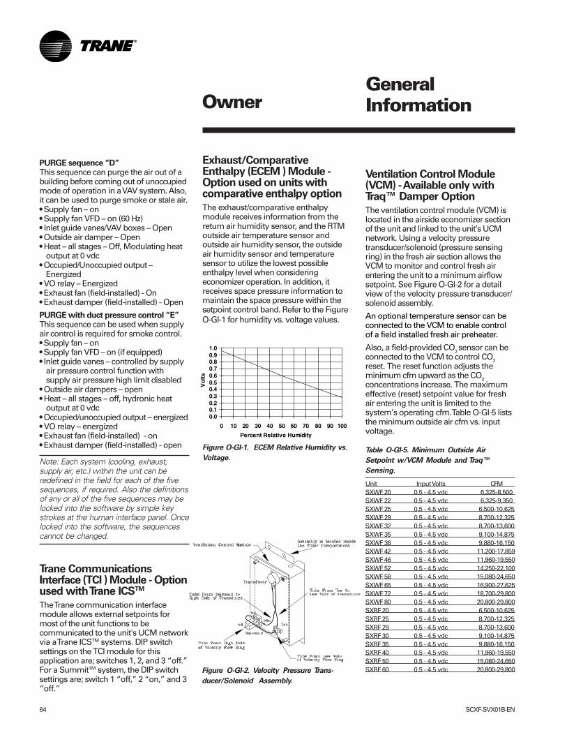
64 SCXF-SVX01B-EN
Figure O-GI-2. Velocity Pressure Trans-
ducer/Solenoid Assembly.
PURGE sequence “D”This sequence can purge the air out of abuilding before coming out of unoccupiedmode of operation in a VAV system. Also,it can be used to purge smoke or stale air.• Supply fan – on• Supply fan VFD – on (60 Hz)• Inlet guide vanes/VAV boxes – Open• Outside air damper – Open• Heat – all stages – Off, Modulating heat
output at 0 vdc• Occupied/Unoccupied output –
Energized• VO relay – Energized• Exhaust fan (field-installed) - On• Exhaust damper (field-installed) - Open
PURGE with duct pressure control “E”This sequence can be used when supplyair control is required for smoke control.• Supply fan – on• Supply fan VFD – on (if equipped)• Inlet guide vanes – controlled by supply
air pressure control function withsupply air pressure high limit disabled
• Outside air dampers – open• Heat – all stages – off, hydronic heat
output at 0 vdc• Occupied/unoccupied output – energized• VO relay – energized• Exhaust fan (field-installed) - on• Exhaust damper (field-installed) - open
Note: Each system (cooling, exhaust,supply air, etc.) within the unit can beredefined in the field for each of the fivesequences, if required. Also the definitionsof any or all of the five sequences may belocked into the software by simple keystrokes at the human interface panel. Oncelocked into the software, the sequencescannot be changed.
Trane CommunicationsInterface (TCI ) Module - Optionused with Trane ICSTM
The Trane communication interfacemodule allows external setpoints formost of the unit functions to becommunicated to the unit's UCM networkvia a Trane ICSTM systems. DIP switchsettings on the TCI module for thisapplication are; switches 1, 2, and 3 “off.”For a SummitTM system, the DIP switchsettings are; switch 1 “off,” 2 “on,” and 3“off.”
OwnerGeneralInformation
Exhaust/ComparativeEnthalpy (ECEM ) Module -Option used on units withcomparative enthalpy option
The exhaust/comparative enthalpymodule receives information from thereturn air humidity sensor, and the RTMoutside air temperature sensor andoutside air humidity sensor, the outsideair humidity sensor and temperaturesensor to utilize the lowest possibleenthalpy level when consideringeconomizer operation. In addition, itreceives space pressure information tomaintain the space pressure within thesetpoint control band. Refer to the FigureO-GI-1 for humidity vs. voltage values.
Ventilation Control Module(VCM) - Available only withTraq™ Damper Option
The ventilation control module (VCM) islocated in the airside economizer sectionof the unit and linked to the unit’s UCMnetwork. Using a velocity pressuretransducer/solenoid (pressure sensingring) in the fresh air section allows theVCM to monitor and control fresh airentering the unit to a minimum airflowsetpoint. See Figure O-GI-2 for a detailview of the velocity pressure transducer/solenoid assembly.
An optional temperature sensor can beconnected to the VCM to enable controlof a field installed fresh air preheater.
Also, a field-provided CO2 sensor can beconnected to the VCM to control CO2reset. The reset function adjusts theminimum cfm upward as the CO2concentrations increase. The maximumeffective (reset) setpoint value for freshair entering the unit is limited to thesystem’s operating cfm. Table O-GI-5 liststhe minimum outside air cfm vs. inputvoltage.
Table O-GI-5. Minimum Outside Air
Setpoint w/VCM Module and Traq™
Sensing.
Unit Input Volts CFMSXWF 20 0.5 - 4.5 vdc 6,325-8,500SXWF 22 0.5 - 4.5 vdc 6,325-9,350SXWF 25 0.5 - 4.5 vdc 6,500-10,625SXWF 29 0.5 - 4.5 vdc 8,700-12,325SXWF 32 0.5 - 4.5 vdc 8,700-13,600SXWF 35 0.5 - 4.5 vdc 9,100-14,875SXWF 38 0.5 - 4.5 vdc 9,880-16,150SXWF 42 0.5 - 4.5 vdc 11,200-17,859SXWF 46 0.5 - 4.5 vdc 11,960-19,550SXWF 52 0.5 - 4.5 vdc 14,250-22,100SXWF 58 0.5 - 4.5 vdc 15,080-24,650SXWF 65 0.5 - 4.5 vdc 16,900-27,625SXWF 72 0.5 - 4.5 vdc 18,700-29,800SXWF 80 0.5 - 4.5 vdc 20,800-29,800SXRF 20 0.5 - 4.5 vdc 6,500-10,625SXRF 25 0.5 - 4.5 vdc 8,700-12,325SXRF 29 0.5 - 4.5 vdc 8,700-13,600SXRF 30 0.5 - 4.5 vdc 9,100-14,875SXRF 35 0.5 - 4.5 vdc 9,880-16,150SXRF 40 0.5 - 4.5 vdc 11,960-19,550SXRF 50 0.5 - 4.5 vdc 15,080-24,650SXRF 60 0.5 - 4.5 vdc 20,800-29,800
Figure O-GI-1. ECEM Relative Humidity vs.
Voltage.
0.00.10.20.30.40.50.60.70.80.91.0
0 10 20 30 40 50 60 70 80 90 100
Percent Relative Humidity
Vo
lts
SCXF-SVX01B-EN 65
Generic Building AutomationSystem Module Option
The generic building automation systemmodule (GBAS) provides broad controlcapabilities for building automationsystems other than Trane’s Tracer®
system. A field provided potentiometeror a 0-5 vdc signal can be applied to anyof the inputs of the GBAS to provide thefollowing points:
GBAS Analog InputsFour analog inputs that can be configured
to be any of the following:(1) Occupied zone cooling(2) Unoccupied zone cooling(3) Occupied zone heating(4) Unoccupied zone heating(5) SA cooling setpoint(6) SA heating setpoint(7) Space static pressure setpoint(8) SA static pressure setpoint
GBAS Binary OutputsFive binary outputs to providediagnostics, signaling up to five alarms.Each of the five (5) relay outputs can bemapped to any/all of the availablediagnostics. Each output contains a dryN.O. and N.C. contact with a VA rating of 2amps at 24 VAC.
GBAS Binary inputOne binary input for the self-containedunit to utilize the demand limit function.This function is operational on units with aGBAS and is used to reduce electricalconsumption at peak load times. Demandlimiting can be set at either 50% or100%. When demand limiting is needed,mechanical cooling and heating (withfield-provided 2-stage electric heat only)operation are either partially (50%), orcompletely disabled (100%) to saveenergy. The demand limit definition isuser definable at the HI panel. Demandlimit binary input accepts a field suppliedswitch or contact closure. When the needfor demand limiting has beendiscontinued, the unit’s cooling/heatingfunctions will again become fully enabled.
GBAS Communication (Analog Inputs)The GBAS accepts external setpoints inthe form of analog inputs for cooling,heating, supply air pressure. Refer to theunit wiring diagram for GBAS inputwiring and the various desired setpointswith the corresponding DC voltageinputs.
OwnerGeneralInformation
Any of the setpoint or output controlparameters can be assigned to each ofthe four analog inputs on the GBASmodule. Also, any combination of thesetpoint and/or output control param-eters can be assigned to the analoginputs through the HI. To assign thesetpoints apply an external 0-5 vdcsignal:1. directly to the signal input terminals, or2. to the 5 vdc source at the GBAS
module with a 3-wire potentiometer.
Note: There is a regulated 5 vdc output onthe GBAS module that can be used with apotentiometer as a voltage divider. Therecommended potentiometer value is1000-100,000 ohms.
The setpoints are linear between thevalues shown in Table O-GI-6 on page 66.Reference Table O-GI-7 on age 66 forcorresponding input voltage setpoints.Following are formulas to calculate inputvoltage or setpoint. SP = setpoint, IPV =input voltage.
If the setpoint range is between 50-90 F:IPV = (SP - 50) (0.1) + 0.5SP = [(IPV - 0.5)/0.1] + 50
If the setpoint range is between 40-90 F:IPV = (SP - 40)(0.8) + 0.5SP = [(IPV - 0.5)/0.08] + 40
If the setpoint range is between 40-180F:IPV = (SP - 40)(0.029) + 0.5SP = [(IPV - 0.5)/0.029] + 40
If the static pressure range is between0.03-0.3 iwc:IPV = (SP - 0.03)(14.8) + 0.5SP = [(IPV - 0.5)/14.8] + 0.03
If the static pressure range is between0.0-5.0 iwc:IPV = (SP)(0.8) + 0.5SP = [IPV/(0.8 + 0.5)]
GBAS Demand Limit Relay (Binary Input)The GBAS allows the unit to utilize thedemand limit function by using anormally open (N.O.) switch to limit theelectrical power usage during peakperiods. Demand limit can initiate by atoggle switch closure, a time clock, or anICS™ control output. These contacts mustbe rated for 12 ma @ 24 VDC minimum.
When the GBAS module receives abinary input signal indicating demandlimiting is required, a command initiatesto either partially (50%) or fully (100%)inhibit compressor and heater operation.This can be set at the HI using the setupmenu, under the “demand limit definitioncooling” and “demand limit definitionheating” screens. A toggle switch, timeclock, or building automation systemcontrol output can initiate demandlimiting.
If the cooling demand limit is set to 50%,half of the cooling capacity will disablewhen the demand limit binary inputcloses. The heating demand limit defini-tion can only be set at 100%, unless theunit has field-provided two-stage electricheat. In that case, if the heating demandlimit is set to 50%, half or one stage ofheating disables when the demand limitbinary input closes. If the demand limitdefinition is set to 100%, then all coolingand/or heating will disable when thedemand limit input closes.
GBAS Diagnostics (Binary Outputs)The GBAS can signal up to 5 alarmdiagnostics, which are fully mappablethrough the setup menu on the HI. Thesediagnostics, along with the alarm outputon the RTM, allow up to six fullymappable alarm outputs.
Each binary output has a NO and NCcontact with a rating of 2 amps at 24 VAC.The five binary outputs are factory presetas shown on the unit wiring diagram (onthe unit control panel door). However,these outputs can be field defined in avariety of configurations, assigning singleor multiple diagnostics to any output.
For a complete listing of possible diagnos-tics, see the IntelliPak® Self-ContainedProgramming Guide, PKG-SVP01B-EN.For terminal strip locations, refer to theunit wiring diagram for the GBAS.
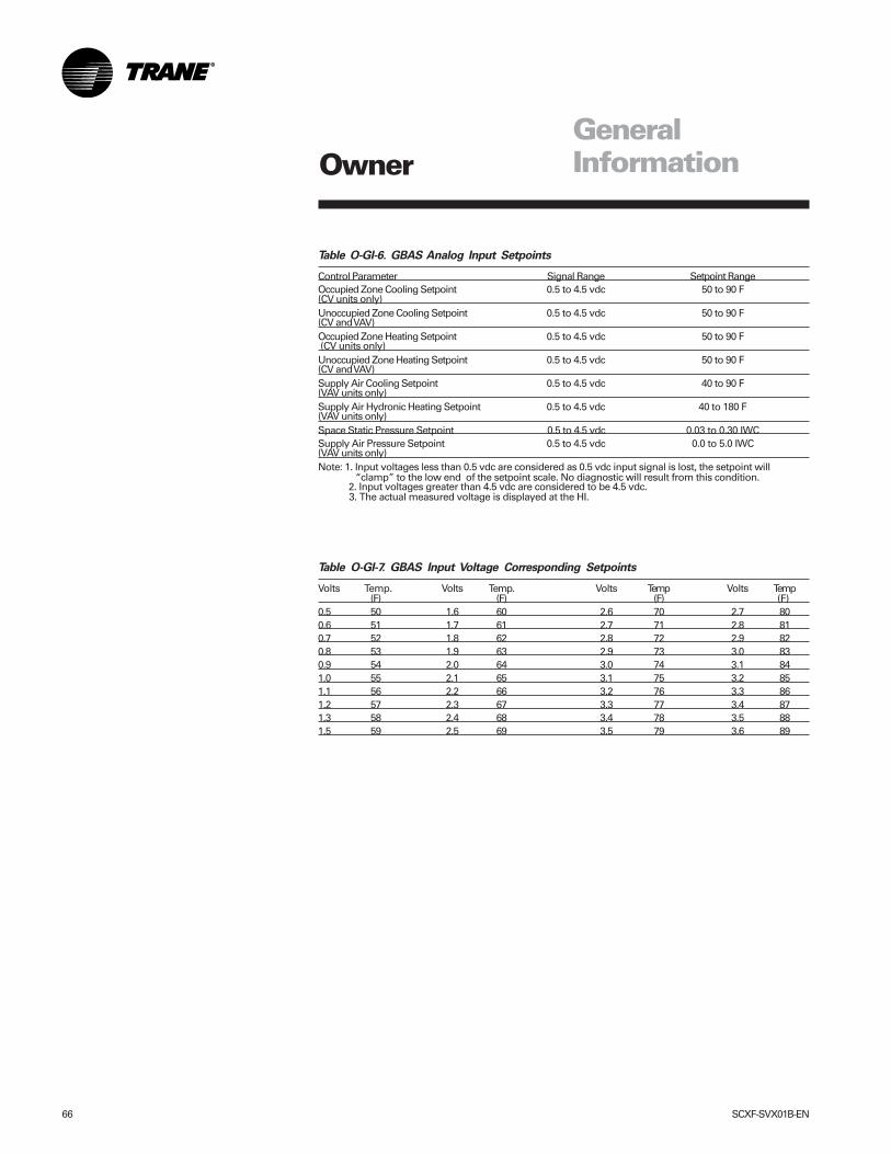
66 SCXF-SVX01B-EN
Table O-GI-6. GBAS Analog Input Setpoints
Control Parameter Signal Range Setpoint RangeOccupied Zone Cooling Setpoint 0.5 to 4.5 vdc 50 to 90 F(CV units only)Unoccupied Zone Cooling Setpoint 0.5 to 4.5 vdc 50 to 90 F(CV and VAV)Occupied Zone Heating Setpoint 0.5 to 4.5 vdc 50 to 90 F (CV units only)Unoccupied Zone Heating Setpoint 0.5 to 4.5 vdc 50 to 90 F(CV and VAV)Supply Air Cooling Setpoint 0.5 to 4.5 vdc 40 to 90 F(VAV units only)Supply Air Hydronic Heating Setpoint 0.5 to 4.5 vdc 40 to 180 F(VAV units only)Space Static Pressure Setpoint 0.5 to 4.5 vdc 0.03 to 0.30 IWCSupply Air Pressure Setpoint 0.5 to 4.5 vdc 0.0 to 5.0 IWC(VAV units only)Note: 1. Input voltages less than 0.5 vdc are considered as 0.5 vdc input signal is lost, the setpoint will “clamp” to the low end of the setpoint scale. No diagnostic will result from this condition. 2. Input voltages greater than 4.5 vdc are considered to be 4.5 vdc. 3. The actual measured voltage is displayed at the HI.
Table O-GI-7. GBAS Input Voltage Corresponding Setpoints
Volts Temp. Volts Temp. Volts Temp Volts Temp(F) (F) (F) (F)
0.5 50 1.6 60 2.6 70 2.7 800.6 51 1.7 61 2.7 71 2.8 810.7 52 1.8 62 2.8 72 2.9 820.8 53 1.9 63 2.9 73 3.0 830.9 54 2.0 64 3.0 74 3.1 841.0 55 2.1 65 3.1 75 3.2 851.1 56 2.2 66 3.2 76 3.3 861.2 57 2.3 67 3.3 77 3.4 871.3 58 2.4 68 3.4 78 3.5 881.5 59 2.5 69 3.5 79 3.6 89
OwnerGeneralInformation
SCXF-SVX01B-EN 67
Waterside Components
Waterside components consist of waterpiping, water valves, water flow switchoption, water cooled condensers (SXWFonly), and the economizer option.
Water PurgeThis user-definable feature allows theuser to select a purge schedule toautomatically circulate water through theeconomizer and condensers periodicallyduring non-operational times. This allowsfresh chemicals to circulate in watersideheat exchangers. This feature is on allunits and is defined at the HI.
Water Piping OptionsWater piping is factory-installed with left-hand connections. Units can be orderedwith either basic piping or intermediatepiping. Also, units with watersideeconomizers can be set for eithervariable or constant water flow at the HI.See Figures O-GI-3, O-GI-4, and O-GI-5 onpage 68 for detailed piping configurationinformation.
With compatible piping configurations,the unit can be configured to provide:1) Constant water flow with basic orintermediate piping or 2) Variable waterflow (head pressure control) withintermediate piping only.
Constant water flow is for condenserpumping systems that are not capable ofunloading the water-pumping system.Variable water flow maximizes energysaving by unloading the water pumpingsystem.
• Basic Water PipingThis option is available on units without awaterside economizer and withcondenser water applications above 54 F(12.2 C) that do not require condensingpressure control. Left hand waterconnections and piping are extended tothe unit exterior. Manifold piping isfactory installed.
• Intermediate Water PipingThis option provides condensingtemperature control when the unit isconfigured (user defined at the HI) forvariable water flow with or without awaterside economizer. A two-waymodulating control valve is wired andinstalled in the unit to maintains a specificrange of water temperature rise throughthe condenser when entering fluid
temperature is less than 58 F (15 C). Thisoption allows the compressor to operatewith entering fluid temperature down to35 F (2 C). The minimum valve position tomaintain minimum condenser flow ratesis user-defined at the HI. This valve drivesclosed if the unit shuts down or if a powerfailure occurs.
• Water Flow Switch OptionA water flow switch is factory installed inthe condenser water pipe within the unit.Whenever the flow switch detects awater flow loss prior to or duringmechanical cooling, compressoroperation locks out and a diagnostic codedisplays. If water flow is restored, thecompressor operation automaticallyrestores.
To prevent injury or death due toinstantaneous release of highpressure water, provide reliefvalves on system water piping.This will also help prevent waterpump damage or stoppage due toexcessive system pressure.
Water-Cooled CondensersUnits that are set up for variable waterflow will modulate a water valve tomaintain a user-defined condensingtemperature setpoint. Condensingtemperature will be referenced utilizingfactory installed sensors located at eachcondenser.
Table O-GI-8. Water Condenser Connection
Sizes
Unit Size Inlet Pipe Outlet PipeSXWF 20, 22, 25, 2 1/2 NPT 2 1/2 NPT29, 32, 35, 38SXWF 42, 46, 52, 3 NPT 3 NPT58, 65, 72, 80
Waterside Economizer OptionThe waterside economizer option takesadvantage of cooling tower water toeither precool the entering air to aid themechanical cooling process or, if thewater temperature is low enough,provide total system cooling. Watersideeconomizing enables when the unit’sentering water temperature is below theunit’s entering mixed air temperature by
OwnerGeneralInformation
����� WARNING!
a minimum of 4 F plus the economizer’sapproach temperature. The approachtemperature default is 4 F. Watersideeconomizing disables when the unit’sentering water temperature is not belowthe unit’s entering mixed air temperatureby at least the water economizerapproach temperature. The approachtemperature defaults to 4 F. Theeconomizer acts as the first stage ofcooling. If the economizer is unable tomaintain the supply air setpoint, the unitcontrol module brings on compressors asrequired to meet the setpoint.
The waterside economizer includes a coil,modulating valves, controls, and pipingwith cleanouts. The coil construction is ½-inch (13 mm) OD seamless copper tubesexpanded into aluminum fins. Theevaporator and economizer coils share acommon sloped (IAQ) drain pan. Drainpan options are either galvanized orstainless steel, and are insulated andinternally trapped.
The waterside economizer coil is avail-able with either a two or four row coil,with no more than 12 fins per inch. Thetubes are arranged in a staggeredpattern to maximize heat transfer. Thecoil has round copper supply and returnheaders with removable cleanout andvent plugs. The optional mechanicalcleanable economizer has removablecast iron headers to allow easy mechani-cal cleaning of the tubes. The watersideworking pressure is rated for 400 psig(2758 kPa).
Waterside Economizer Flow ControlUnits equipped with a watersideeconomizer can be set from the humaninterface panel for variable or constantwater flow.
• Constant Water FlowTwo-way modulating control shutoffvalves are wired, controlled, and installedin the unit. One valve is located in theeconomizer’s water inlet, and the other isin the condenser bypass water inlet.When the waterside economizer enables,the two-way valves modulate to maintainthe discharge air temperature setpoint.As the economizer valve opens, thecondenser bypass valve closes, and viceversa. Full water flow is alwaysmaintained through the condensers. Bothvalves will close in the event of a powerfailure.
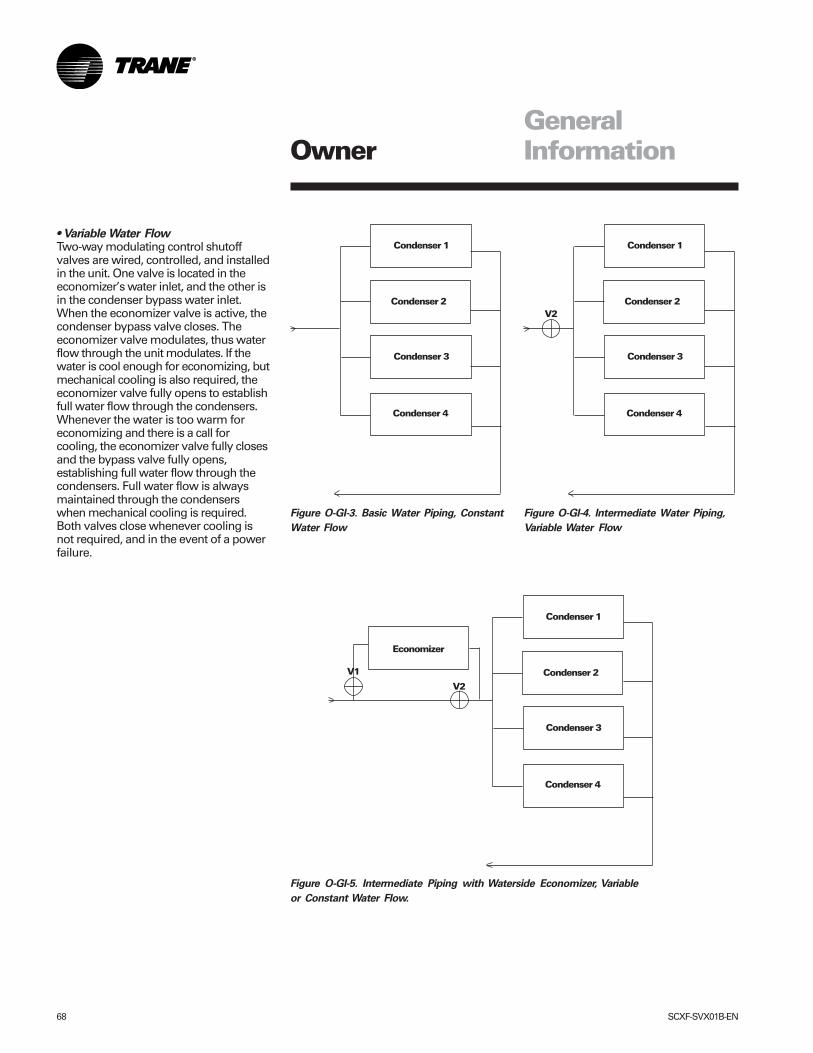
68 SCXF-SVX01B-EN
Owner
Condenser 1
Condenser 2
Condenser 3
Condenser 4
V2
Condenser 1
Condenser 2
Condenser 3
Condenser 4
V1
Economizer
Condenser 1
Condenser 2
Condenser 3
Condenser 4
V2
Figure O-GI-3. Basic Water Piping, Constant
Water Flow
Figure O-GI-4. Intermediate Water Piping,
Variable Water Flow
Figure O-GI-5. Intermediate Piping with Waterside Economizer, Variable
or Constant Water Flow.
GeneralInformation
• Variable Water FlowTwo-way modulating control shutoffvalves are wired, controlled, and installedin the unit. One valve is located in theeconomizer’s water inlet, and the other isin the condenser bypass water inlet.When the economizer valve is active, thecondenser bypass valve closes. Theeconomizer valve modulates, thus waterflow through the unit modulates. If thewater is cool enough for economizing, butmechanical cooling is also required, theeconomizer valve fully opens to establishfull water flow through the condensers.Whenever the water is too warm foreconomizing and there is a call forcooling, the economizer valve fully closesand the bypass valve fully opens,establishing full water flow through thecondensers. Full water flow is alwaysmaintained through the condenserswhen mechanical cooling is required.Both valves close whenever cooling isnot required, and in the event of a powerfailure.
SCXF-SVX01B-EN 69
Owner
Unit Airside Components
The unit’s air delivery system consists ofcondensers, dampers, enthalpy switchoption, airside economizer option, filters,low ambient sensors, and factorymounted single or double wall plenums.
Supply Air FanThe unit has a single supply fan that runsat a constant speed. However, the fanmay have the IGV or VFD option thatmodulates airflow based on supply airtemperature control. Pressing the stopkey on the HI will turn the supply fan off.The fan is on continuously when a CV unitis in occupied mode and except when aunit is in the night heat/morning warmupmode. During the night heat and setbackmode the fan cycles on and off inresponse to a call for heat. See Table O-GI-9 for available fan horsepower.
Low Entering Air Temperature SensorThis is standard on all units with ahydronic coil or waterside economizer. Itcan also be ordered as an option.
A thermostat limit switch is factorymounted on the unit’s entering air sidewith a capillary tube serpentine acrossthe coil face. If the temperature fallsbelow 35 F (2 C), the fan shuts down andthe waterside economizer and/orhydronic heat valve options open to allowfull water flow. The heat output alsoenergizes. A manual reset is required.The low entering air temperaturesetpoint is adjustable at the HI.
High Duct Temperature ThermostatA factory-supplied temperature limitswitch with reset element detects thesupply air duct temperature. This sensorshould be field-installed downstreamfrom the unit’s discharge in the supply airduct. If the supply air duct temperatureexceeds 240 F (115.6 C), the unit shutsdown and displays a diagnostic. Amanual reset is required at the unit. Thehigh duct temperature can be adjusted atthe thermostat.
Dirty Filter Sensor OptionA factory installed pressure switchsenses the pressure differential acrossthe filters. When the differential pressureexceeds 0.9-inches (23 mm) WG, contactclosure occurs and the HI will display adiagnostic. The unit will continue to rununtil you replace the air filters.
A field installed indicator device may bewired to relay terminals to indicate whenfilter service is required. Contacts arerated at 115 VAC and are powered by afield supplied transformer.
Low Ambient Sensor (Air-Cooled Units)The low ambient sensor is field-installedon air-cooled units. Position it in a locationsubject to ambient temperatures onlyand not exposed to direct sunlight orexhaust fans.
The low pressure cutout initiates basedon the ambient temperature. A timedelay on the low pressure cutout initiatesfor ambient temperatures between 50(zero minutes) and 0 F (10 minutes). Thishelps to prevent nuisance low pressurecutout trips.
Inlet Guide Vane OptionInlet guide vanes (IGV’s) are driven by amodulating 0-10 vdc signal from the RTMmodule. A pressure transducermeasures duct static pressure, and theIGV’s modulate to maintain the supply airstatic pressure within an adjustable user-defined range. The range is determinedby the supply air pressure setpoint andsupply air pressure deadband, which areset through the HI panel.
IGV assemblies installed on the supplyfan inlet regulate fan capacity and limithorsepower at lower system air require-ments. When in any position other thanfull open, the vanes pre-spin the air in thesame direction as the supply fan rotation.As the vanes approach the full-closedposition, the amount of “spin” induced bythe vanes increases at the same timethat intake airflow and fan horsepowerdiminish. The IGV’s will close when thesupply fan is off.
Supply Air Static Pressure LimitThe opening of the IGV’s and VAV boxescoordinate during unit startup andtransition to/from occupied/unoccupied
modes to prevent supply air ductoverpressurization. However, if for anyreason the supply air pressure exceedsthe user-defined supply air staticpressure limit set at the HI panel, thesupply fan/VFD shuts down and the IGV’sclose. The unit will attempt to restart, upto three times. If the overpressurizationcondition still occurs on the third restart,the unit shuts down and a manual resetdiagnostic sets and displays at the HI.
Variable Frequency Drive OptionThe variable frequency drive (VFD) isdriven by a modulating 0-10 vdc signalfrom the RTM module. A pressuretransducer measures duct staticpressure, and the VFD adjusts the fanspeed to maintain the supply air staticpressure within an adjustable user-defined range. The range is determinedby the supply air pressure setpoint andsupply air pressure deadband, which areset at the HI panel.
VFD’s provide supply fan motor speedmodulation. The drives will accelerate ordecelerate as required to maintain thesupply air static pressure setpoint.
VFD with BypassBypass control is an option that providesfull nominal airflow in the event of drivefailure. The user must initiate the bypassmode at the HI panel. When in bypassmode, VAV boxes need to be fully open.The self-contained unit will controlheating and cooling functions to maintainsetpoint from a user-defined zone sensor.Supply air static pressure limit is active inthis mode.
For more detailed information on VFDoperation, reference the Square D VFDtechnical manual that ships with the unit.
Airside Economizer OptionUnits with the airside economizer optionare equipped with the necessary controlsequences to use outside air for the first
Table O-GI-9. Supply Fan Horsepower Selections.
Unit Model HPSXRF SXWF 5 7.5 10 15 25 30 40 5020 20, 22, 25 X X X X X25, 29 29, 32 X X X X30, 35 35, 38 X X X X40 42, 46 X X X X X50 52, 58, 65 X X X X X X60 72, 80 X X X X X X
GeneralInformation
70 SCXF-SVX01B-EN
Owner
stage of cooling, in occupied orunoccupied mode and when ambientconditions are favorable for economizing.Inherent in the unit controller is the abilityto suppress the setpoint below thenormal unit setpoint. This allows thebuilding to improve comfort levels whenpossible, and at the same time, optimizebuilding mechanical cooling operation forpeak operating efficiency. An outside airtemperature and relative humiditysensor are provided to allow monitoringof reference enthalpy and are fieldinstalled.
If the unit has the ECEM board, econo-mizer operation enables when theoutside air enthalpy is less than 25 BTU’s/lb. default (adjustable 19-28 BTU’s/lb).During occupied mode, the outside airdamper opens to 15% (adjustable 0-100% at the HI) for ventilation purposes.Also, the ability to alter the outside airdamper position to compensate for VAVsupply air modulation is inherent in theunit controls, and can be enabled by theoperator.
If the unit does not have an ECEM board,it will economize when the O/A tempera-ture falls below the O/A economizersetpoint.
The mixing box fabrication is 16-gaugegalvanized steel. Opposed low leakdamper blades are fabricated from 16-gauge galvanized steel and rotate onrustproof nylon bushings. A factoryinstalled 24V modulating spring returnactuator controls both damper positions.
When outdoor conditions are not suitablefor economizer cooling, the enthalpycontrol disables the economizer functionand permits the outdoor air damper toopen only to the minimum position.
On water-cooled units, compressoroperation lockout will not occur at lowambient air temperatures. However,lockout will still occur via low condenserwater temperature.
The outdoor air dampers drive fullyclosed whenever the supply air fan is off,provided there is power to the unit.
Comparative Enthalpy ControlComparative enthalpy controls theeconomizer operation and measurestemperature and humidity of both returnair and outside air to determine which
GeneralInformation
source has lower enthalpy. This allowstrue comparison of outdoor air and returnair enthalpy by measurement of outdoorair and return air temperatures andhumidities. A factory-installed controlboard, with field-installed outside andreturn air temperature and relativehumidity sensors, allows monitoring ofoutside and return air.
Note: If comparative enthalpy is notordered, the standard method is tocompare outdoor air enthalpy with thefixed reference enthalpy. The referenceenthalpy is set through the humaninterface panel.
Units with comparative enthalpy controlare equipped with the necessary controlsequences to allow using outside air forthe first stage of cooling, in occupied orunoccupied mode and when ambientconditions are favorable for economizing.Inherent in the unit controller is the abilityto suppress the setpoint below thenormal unit setpoint. This allows thebuilding to improve comfort levels whenpossible, and at the same time, optimizebuilding mechanical cooling operation forpeak operating efficiency.
Economizer operation enables when theoutside air enthalpy is 3 BTU’s/lb. lessthan the return air enthalpy. Duringoccupied mode, the outside air damperopens to 15% (adjustable 0-100%) forventilation purposes. Also, the ability toalter the outside air damper position tocompensate for VAV supply air modula-tion is inherent in the unit controls, andcan be enabled by the operator.
The mixing box fabrication is 16-gaugegalvanized steel. Opposed low leakdamper blades are fabricated from 16-gauge galvanized steel and rotate onrustproof nylon bushings. A factoryinstalled 24V modulating spring returnactuator controls both damper positions.
Airside Economizers with TraqTM DamperOutside air enters the unit through theTraqTM damper assembly and ismeasured by velocity pressure flowrings. The velocity pressure flow ringsare connected to a pressure transducer/solenoid assembly, which compensatesfor temperature swings that could affectthe transducer. The ventilation control
module (VCM) utilizes the velocitypressure input, the RTM outdoor airtemperature input, and the minimumoutside air CFM setpoint to modify thevolume (CFM) of fresh air entering theunit as the measured airflow deviatesfrom setpoint.
When the optional preheat temperaturesensor is installed at the auxiliarytemperature on the VCM and the preheatfunction is enabled, the sensor willmonitor the combined (averaged) freshair and return air temperatures. As thismixed air temperature falls below thepreheat actuate temperature setpoint,the VCM activates the preheat binaryoutput to control a field-installed heater.The output deactivates when the tem-perature rises 5 F above the preheatactuate temperature setpoint.
Using a field-installed CO2 sensor withCO2 reset enabled, as the CO2 concentra-tion increases above the CO2 reset startvalue, the VCM modifies the minimumoutside air CFM setpoint to increase theamount of fresh air entering the unit. Thesetpoint adjusts upward until reaching theCO2 maximum reset value. The maxi-mum effective (reset) setpoint value forfresh air is limited to the system’soperating CFM. As the CO2 concentrationdecreases, the effective (reset) setpointvalue adjusts downward toward theminimum outside air CFM setpoint. SeeFigure O-GI-6 on page 71 for an airflowcfm vs. CO2 concentration curve.
Standard Two-Position Damper InterfaceUnits with the two-position damperinterface are provided with a 0-10 VDCcontrol output suitable for controlling afield-provided modulating actuator. Inoccupied mode, the output drives to themaximum position.
Airside Economizer InterfaceUnits with airside economizer interfaceare equipped with the necessary controlsequences to allow using outside air forthe first stage of cooling, in occupied orunoccupied mode and when ambientconditions are favorable for economizing.Inherent in the unit controller is the abilityto suppress the setpoint below thenormal unit setpoint. This allows thebuilding to improve comfort levels whenpossible, and at the same time, optimizebuilding mechanical cooling operation for
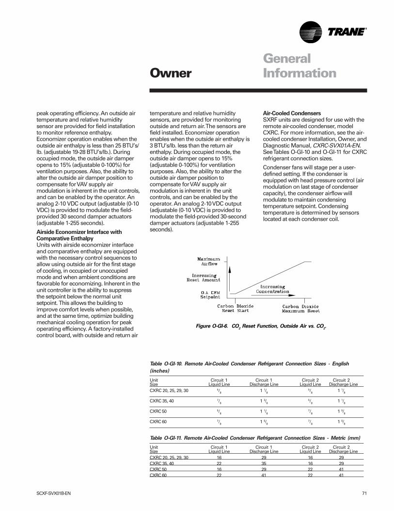
SCXF-SVX01B-EN 71
Table O-GI-10. Remote Air-Cooled Condenser Refrigerant Connection Sizes - English
(inches)
Unit Circuit 1 Circuit 1 Circuit 2 Circuit 2Size Liquid Line Discharge Line Liquid Line Discharge LineCXRC 20, 25, 29, 30 5/8 1 1/8
5/8 1 1/8
CXRC 35, 40 7/8 1 3/85/8 1 1/8
CXRC 50 5/8 1 1/87/8 1 5/8
CXRC 60 7/8 1 5/87/8 1 5/8
Table O-GI-11. Remote Air-Cooled Condenser Refrigerant Connection Sizes - Metric (mm)
Unit Circuit 1 Circuit 1 Circuit 2 Circuit 2Size Liquid Line Discharge Line Liquid Line Discharge LineCXRC 20, 25, 29, 30 16 29 16 29CXRC 35, 40 22 35 16 29CXRC 50 16 29 22 41CXRC 60 22 41 22 41
peak operating efficiency. An outside airtemperature and relative humiditysensor are provided for field installationto monitor reference enthalpy.Economizer operation enables when theoutside air enthalpy is less than 25 BTU’s/lb. (adjustable 19-28 BTU’s/lb.). Duringoccupied mode, the outside air damperopens to 15% (adjustable 0-100%) forventilation purposes. Also, the ability toalter the outside air damper position tocompensate for VAV supply airmodulation is inherent in the unit controls,and can be enabled by the operator. Ananalog 2-10 VDC output (adjustable (0-10VDC) is provided to modulate the field-provided 30 second damper actuators(adjustable 1-255 seconds).
Airside Economizer Interface withComparative EnthalpyUnits with airside economizer interfaceand comparative enthalpy are equippedwith the necessary control sequences toallow using outside air for the first stageof cooling, in occupied or unoccupiedmode and when ambient conditions arefavorable for economizing. Inherent in theunit controller is the ability to suppressthe setpoint below the normal unitsetpoint. This allows the building toimprove comfort levels when possible,and at the same time, optimize buildingmechanical cooling operation for peakoperating efficiency. A factory-installedcontrol board, with outside and return air
temperature and relative humiditysensors, are provided for monitoringoutside and return air. The sensors arefield installed. Economizer operationenables when the outside air enthalpy is3 BTU’s/lb. less than the return airenthalpy. During occupied mode, theoutside air damper opens to 15%(adjustable 0-100%) for ventilationpurposes. Also, the ability to alter theoutside air damper position tocompensate for VAV supply airmodulation is inherent in the unitcontrols, and can be enabled by theoperator. An analog 2-10 VDC output(adjustable (0-10 VDC) is provided tomodulate the field-provided 30-seconddamper actuators (adjustable 1-255seconds).
Figure O-GI-6. CO2 Reset Function, Outside Air vs. CO
2.
OwnerGeneralInformation
Air-Cooled CondensersSXRF units are designed for use with theremote air-cooled condenser, modelCXRC. For more information, see the air-cooled condenser Installation, Owner, andDiagnostic Manual, CXRC-SVX01A-EN.See Tables O-GI-10 and O-GI-11 for CXRCrefrigerant connection sizes.
Condenser fans will stage per a user-defined setting. If the condenser isequipped with head pressure control (airmodulation on last stage of condensercapacity), the condenser airflow willmodulate to maintain condensingtemperature setpoint. Condensingtemperature is determined by sensorslocated at each condenser coil.
72 SCXF-SVX01B-EN
Input Devices and SystemFunctions
Following are basic input device andsystem function descriptions used withinthe UCM network on IntelliPak® self-contained units. Refer to the unit wiringdiagrams for specific connections.
Water PurgeDuring the unoccupied mode, water-cooled units will periodically circulatewater through the condensers andwaterside economizer if the user hasenabled the purge function at the HI.
The water purge function circulateswater to introduce fresh water-treatmentchemicals and help prevent waterstagnation. The number of hours be-tween each periodic purge, or purgeduration, is user-defined at the HIbetween 1-999 hours. If the periodicpurge timer expires while the unit is inoccupied mode, it will wait for the nextavailable unoccupied time beforeinitiating water purge. Contrary, if arequest for cooling occurs during a purgesequence, purge will terminate andcooling will commence.
Compressor Circuit BreakersThe compressors are protected by circuitbreakers that interrupt the compressorpower supply if the current exceeds thebreakers “must trip” value. During arequest for compressor operation, if thecompressor module (MCM or SCM)detects a problem outside of it’s normalparameters, it turns any operatingcompressor(s) on that circuit off, locks outall compressor operation for that circuit,and initiates a manual reset diagnostic.
Compressor Motor WindingThermostatsA thermostat is embedded in the motorwindings of each compressor. Eachthermostat opens if the motor windingsexceed approximately 221 F. Thethermostat resets automatically whenthe winding temperature decreases toapproximately 181 F. Rapid cycling, lossof charge, abnormally high suctiontemperatures, or the compressor runningbackwards could cause the thermostat toopen. During a request for compressoroperation, if the compressor moduledetects a problem outside of it's normalparameters, it turns any operatingcompressor(s) on that circuit off, locks out
all compressor operation for that circuit,and initiates a manual reset diagnostic.
Low Pressure ControlLow pressure (LP) control isaccomplished using a binary input device.LP cutouts are mounted on the suctionlines near the compressors.
The LP control contacts close when thesuction pressure exceeds 27 ± 4 psig. Ifthe LP control is open when a compres-sor starts, none of the compressors onthat circuit will operate. They are lockedout and a manual reset diagnosticinitiates.
The LP cutouts open if the suctionpressure approaches 7 ± 4 psig. If the LPcutout opens after a compressor starts,all compressors operating on that circuitwill turn off immediately and will remainoff for a minimum of three minutes.
If the LP cutout trips four consecutivetimes during the first three minutes ofoperation, the compressors on that circuitwill lock out and a manual reset diagnos-tic initiates.
Evaporator Temperature SensorFrostat™The evaporator temperature sensor is ananalog input device used to monitorrefrigerant temperature inside theevaporator coil to prevent coil freezing. Itis attached to the suction line near theevaporator coil with circuits 1 and 2connected to the SCM/MCM and circuits3 and 4 connected to the WSM. The coilfrost cutout temperature is factory set at30 F. It is adjustable at the HI from 25-35 F.The compressors stage off as necessaryto prevent icing. After the lastcompressor stages off, the compressorswill restart when the evaporatortemperature rises 10 F above the coilfrost cutout temperature and theminimum three minute “off” timeelapses.
Saturated Condenser TemperatureSensorsThe saturated condenser temperaturesensors are analog input devices. Theyare mounted inside a temperature welllocated on a condenser tube bend on air-cooled units, and in the condenser shellon water-cooled units. The sensorsmonitor the saturated refrigeranttemperature inside the condenser coil
and are connected to the SCM/MCM forcircuits 1 and 2 (air or water cooled), andWSM for circuits 3 and 4 (only water-cooled).
Head Pressure ControlHead pressure control is accomplishedusing two saturated refrigeranttemperature sensors on air-cooled unitsand up to four sensors on water-cooledunits.
• Air-cooled units: During a request forcompressor operation when the con-densing temperature rises above thelower limit of the control band, thecompressor module (SCM/MCM)sequences condenser fans on. If theoperating fans cannot bring the condens-ing temperature to within the controlband, more fans turn on. As the satu-rated condensing temperature ap-proaches the lower limit of the controlband, fans sequence off. The minimumon/off time for condenser fan staging is5.2 seconds. If the system is operating ata given fan stage below 100% for 30minutes he saturated condensingtemperature is above the efficiencycheck point setting, a fan stage will beadded. If the saturated condensingtemperature falls below the efficiencycheck point setting, fan control remains atthe present operating stage. If the fanstage cycles four times within a 10minute period, the lower limit tempera-ture is redefined as being equal to thelower limit minus the temporary low limitsuppression setting. The unit will utilizethis new low limit temperature for onehour to reduce condenser fan shortcycling.
• Water-cooled: Units without WSE, thecondenser valve modulates to maintainan average saturated condensertemperature. Units with WSE, if econo-mizing and mechanical cooling is neces-sary the economize valve will sacrificefree cooling and modulate to maintaincondensing saturated temperature. If noteconomizing, the condenser valve willmodulate to maintain condensingsaturated temperature.
Water-cooled units without head pres-sure control will lock out mechanicalcooling at entering condenser watertemperatures below 54 F. Mechanicalcooling will resume when the entering
OwnerGeneralInformation
SCXF-SVX01B-EN 73
condenser water temperature exceeds58 F.
Low Ambient Control (Air-Cooled UnitsOnly)The low ambient modulating output onthe compressor module is functional onall units with or without the low ambientoption. When the compressor modulestages up to it's highest stage (stage 2 or3 depending on unit size), the modulatingoutput is 100% (10 VDC). When thecontrol is at stage 1, the modulatingoutput (0 to 10 VDC) controls thesaturated condensing temperature towithin the programmable condensingtemperature low ambient control point.
Low Ambient Compressor Lockout (Air-Cooled Units Only)The low ambient compressor lockoututilizes an analog input device. When thesystem is configured for low ambientcompressor lockout, the compressors willnot operate if the temperature of theoutside air falls below the lockoutsetpoint. When the temperature rises 5 Fabove the lockout setpoint, thecompressors will operate. The setpointfor units without the low ambient option is50 F. For units with the low ambientoption, the setpoint is 0 F. The setpointsare adjustable at the human interfacepanel.
Return Air Temperature SensorThe return air temperature sensor is ananalog input device used with a returnhumidity sensor on units with thecomparative enthalpy option. The sensormonitors the return air temperature andcompares it to the outdoor temperatureto establish which temperature is bestsuited to maintain cooling requirements.It is mounted in the return air path andconnected to the ECEM.
Supply Fan Circuit Breaker, Fuses, andOverloadsThe supply fan motor is protected byeither circuit breakers fuses or acombination of fuses and overloads,dependent upon unit configuration. Circuitbreakers are used on units without VFD’s.They will trip and interrupt the motorpower supply if the current exceeds thebreaker trip value. The RTM shuts allsystem functions off when detecting anopen fan proving switch. Units with VFD’shave fuses to protect the VFD and motor.
Units with VFD w/bypass have fuses toprotect VFD circuit and overloads toprotect the motor when in bypass.
Supply Air Temperature Low LimitThe supply air temperature low limitfunction uses the supply air temperaturesensor input to modulate the economizerdamper to the minimum position if thesupply air temperature falls below theoccupied heating setpoint temperature.
Supply Air Temperature SensorThe supply air temperature sensor is ananalog input device. It monitors thesupply air temperature for supply airtemperature control, supply airtemperature reset, supply airtemperature low limiting, and supply airtempering. It is mounted in the supply airdischarge section of the unit andconnected to the RTM.
Supply Airflow Proving SwitchesThis is binary input device used on unitsto signal the RTM when the supply fan isoperating. It is mounted in the supply fansection and is connected to the RTM.During a request for fan operation and ifthe differential switch opens for 40consecutive seconds, compressoroperation turns off, heat operation turnsoff, the request for supply fan operation isturns off and locks out, IGV option closes,economizer damper option closes, and amanual reset diagnostic initiates.
Low Entering Air Protection Device(LEATPD)The low entering air protection device(LEATPD) is a binary input on units withhydronic heat or a waterside economizer.It is optional on water-cooled units.
If the LEATPD is on a unit with factory-installed heat, it is mounted in the heatsection and connected to the heatmodule. If the entering air temperature tothe heating coil falls to 40 F, the normallyopen contacts on the LEATPD close andcause the following events:a. the hydronic heat actuator fully opens.b. the supply fan turns offc. the outside air damper closesd. the SERVICE light at the remote zone
sensor option turns on.e. a LEATPD diagnostic displays at the
human interface panel.
If the LEATPD is on a water-cooled unitwithout factory-installed heat, it is wired
to the WSM. It will trip if the enteringwater temperature falls to 34 F, open theeconomizer valve, and energize thepump output.
High Duct Temp Thermostat Option OnUnits with a TCIThe high duct temperature thermostatsare binary input devices used on unitswith a Trane communication interfacemodule (TCI). They provide a high limitunit shutdown and require a manualreset. The thermostats are factory set toopen if the supply air temperaturereaches 240 F, or the return airtemperature reaches 135 F. Once tripped,the thermostat requires a manual reset.Reset by pressing the sensor’s resetbutton when the air temperaturedecreases approximately 25 F below thecutout point.
Filter SwitchThe filter switch is a binary input devicethat measures the pressure differentialacross the unit filters. It is mounted in thefilter section and connected to the RTM. Adiagnostic SERVICE signal displays at theremote panel if the pressure differentialacross the filters is at least 0.5” w.c. Thecontacts automatically open when thepressure differential across the filtersdecrease to 0.4” w.c. The switchdifferential is field adjustable between0.17” to 5.0” w.c. ± 0.05 “.
High Duct Static Switch OptionThe high duct static switch is field-mounted in the ductwork or plenums withsmoke dampers. It will cause a manualreset diagnostic if the duct static exceedsthe pre-set static limit. The static limit isadjustable at the HI.
OwnerGeneralInformation
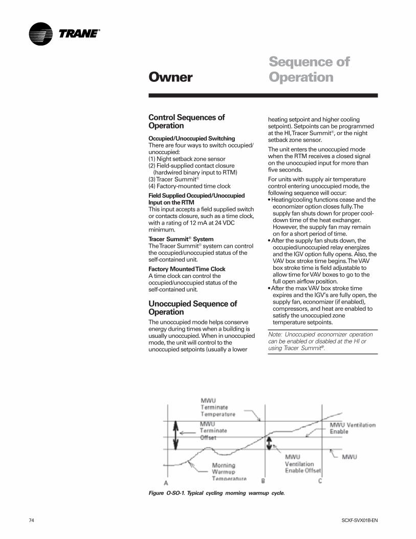
74 SCXF-SVX01B-EN
Owner
Control Sequences ofOperation
Occupied/Unoccupied SwitchingThere are four ways to switch occupied/unoccupied:(1) Night setback zone sensor(2) Field-supplied contact closure
(hardwired binary input to RTM)(3) Tracer Summit®
(4) Factory-mounted time clock
Field Supplied Occupied/UnoccupiedInput on the RTMThis input accepts a field supplied switchor contacts closure, such as a time clock,with a rating of 12 mA at 24 VDCminimum.
Tracer Summit® SystemThe Tracer Summit® system can controlthe occupied/unoccupied status of theself-contained unit.
Factory Mounted Time ClockA time clock can control theoccupied/unoccupied status of theself-contained unit.
Unoccupied Sequence ofOperation
The unoccupied mode helps conserveenergy during times when a building isusually unoccupied. When in unoccupiedmode, the unit will control to theunoccupied setpoints (usually a lower
Figure O-SO-1. Typical cycling morning warmup cycle.
Sequence ofOperation
heating setpoint and higher coolingsetpoint). Setpoints can be programmedat the HI, Tracer Summit®, or the nightsetback zone sensor.
The unit enters the unoccupied modewhen the RTM receives a closed signalon the unoccupied input for more thanfive seconds.
For units with supply air temperaturecontrol entering unoccupied mode, thefollowing sequence will occur:• Heating/cooling functions cease and the
economizer option closes fully. Thesupply fan shuts down for proper cool-down time of the heat exchanger.However, the supply fan may remainon for a short period of time.
• After the supply fan shuts down, theoccupied/unoccupied relay energizesand the IGV option fully opens. Also, theVAV box stroke time begins. The VAVbox stroke time is field adjustable toallow time for VAV boxes to go to thefull open airflow position.
• After the max VAV box stroke timeexpires and the IGV’s are fully open, thesupply fan, economizer (if enabled),compressors, and heat are enabled tosatisfy the unoccupied zonetemperature setpoints.
Note: Unoccupied economizer operationcan be enabled or disabled at the HI orusing Tracer Summit®.
SCXF-SVX01B-EN 75
OwnerSequence ofOperation
is reached. Next a 60 minute timerbegins. If the building load reaches theMWU ventilation setpoint, or the the 60minutes expire, whichever is first, theairside economizer will control to theminimum position. MWU will end whenthe zone temperature rises above theMWU terminate setpoint.
Timed Override Activation - ICS™This function is operational whenever theunit’s RTM module is used as the zonetemperature sensor source, which can beset at the HI panel. When this function isinitiated by the push of the overridebutton on the zone sensor, the unit willswitch to the occupied mode. Unitoperation (occupied mode) during timedoverride is terminated by a signal fromTracer®.
Timed Override Activation - Non-ICSThis function is active whenever the unit’sRTM module board is selected as thezone temperature source, which can beset at the human interface panel. Whenthis function is initiated by the push of theoverride button on the zone sensor, theunit will switch to the occupied mode.Automatic cancellation of the timedoverride mode occurs after three hoursof operation.
VAV Drive Max OutputThis is a single-pole, double-throw relayrated at a maximum voltage of 24 vac, 2amps max. The relay contacts of thisrelay switch when the unit goes from theoccupied mode to the unoccupied modeby means of the unoccupied binary input,night setback zone sensor, or TracerSummit®. The contacts will stay switchedduring the unoccupied and morningwarmup mode. They will return to theposition shown on the unit wiringdiagram when the unit returns to theoccupied mode. The intent of this binaryoutput is to signal the VAV boxes or otherterminal devices to go to a full openairflow position.
For units without volume control enteringunoccupied mode, the following se-quence will occur:
• The occupied/unoccupied relay ener-gizes and the economizer option fullycloses.• The fan mode is set to auto and the unit
will control to the unoccupied zonetemperature setpoints.
With MWU enabled at the HI, if the zonetemperature is below the MWU setpoint,the unit enters the MWU mode.
Morning WarmupThis feature can be enabled at the HI, andcan be used with factory or field-installedheat. If MWU is not required disable thefunction in the setup menu at the HI.MWU transitions the zone fromunoccupied to occupied. It will heat untilthe MWU setpoint is met. The unit is thenreleased to occupied mode. Supply ductstatic pressure is maintained during thissequence. MWU can be set (at the HI) tofunction as either full or cycling capacity.
Full Capacity Morning Warmup (MWU)Full capacity morning warmup uses fullheating capacity to heat the zone asquickly as possible. Full heating capacityis provided until the morning warmupsetpoint is met. At this point, the unit isreleased to daytime mode.
Cycling Capacity Morning Warmup(MWU)Cycling capacity morning warmupprovides a more gradual heating toovercome “building sink” as the zone isheated. Normal zone temperature controlwith varying capacity is used to raise thezone temperature to the MWU zonetemperature setpoint. This method ofwarmup is used to overcome the“building sink” effect.
Reference Figure O-SO-1 on page 74 fora pictorial explanation of the cyclingMWU sequence. Cycling capacity MWUwill heat until MWU temperature setpoint
76 SCXF-SVX01B-EN
OwnerSequence ofOperation
Occupied Sequence OfOperation
All setpoints can be adjusted using the HIpanel. Also, cooling/heating setpoints canbe adjusted in the zone, if using one of thezone sensor options (BAYSENS020,BAYSENS021, BAYSENS008,BAYSENS010, BAYSENS019, orBAYSENS014). For a complete list of unitsetpoint default values and ranges, seethe IntelliPak® Self-ContainedProgramming Guide, PKG-SVP01B-EN.
Occupied Zone Temperature - CoolingThe unit transitions from unoccupied tooccupied when the occupied/unoccupiedinput on the RTM is open for more thanfive seconds after having been closed.This input can be received from TracerSummit®, the remote NSB zone sensor,the timed override function, or a fieldsupplied contact. Dependent on unitoptions and the HI programming, thefollowing sequence will occur:• The unit will begin MWU and then
switch to the occupied mode after theMWU setpoint is met.
• Purge will be enabled by TracerSummit®. Then Tracer Summit® willenable the occupied mode.
• The unit will switch from unoccupied tooccupied control immediately.
Upon entering occupied mode,the IGVoption will close while the supply fanremains on. The occupied/unoccupiedrelay will de-energize.
Zone Temperature Control(Unit Model Number Digit 9 = 4 or 5)A zone sensor located directly in thespace sends input to the RTM while theCV unit is in occupied cooling mode.When the unit is in occupied cooling, theRTM controls the zone temperaturewithin the cooling setpoint deadband bymodulating the economizer option and/orstaging mechanical cooling on and off asrequired.
Supply Air Temperature Control(Unit Model Number Digit 9 = 1, 2, 3, or 6)When the VAV unit is in occupied cooling,the RTM controls the supply airtemperature to the specified supply aircooling setpoint by modulating theeconomizer option and/or stagingmechanical cooling on and off asrequired. The changeover relay contacts(field supplied) must be open on units
with hydronic heat for cooling to operate.
CoolingUpon entering occupied mode, the RTMreceives an input from either the HI, RHI,Tracer Summit®, or the GBAS to start thesupply fan. The RTM supply fan contactsclose and energize the supply fancontactor. On VAV units with IGV, the fandelays until the IGV fully close. When thesupply fan starts, the fan proving switchcloses, signaling the RTM that airflow isestablished. Depending on unit options,either the IGV will begin to drive open, theVFD will ramp the fan, and/or the airsideeconomizer dampers will open to theuser-defined minimum position.
When a cooling request is sent to theRTM from the zone sensor, the RTMevaluates the system operating condi-tions using the supply air and outdoortemperature input before sending therequest to the MCM for mechanicalcooling. If outdoor conditions (tempera-ture and humidity) are suitable or theEWT is within specified setpoints, theRTM will attempt to use “free cooling”without using any compressors. The RTMwill use either the airside or watersideeconomizer option. When outdoor airconditions are not suitable, only mechani-cal cooling will function and outside airdampers will remain at their minimumposition. If the unit does not have aneconomizer, mechanical cooling willoperate to satisfy cooling requirements.
Units With EconomizerIf the entering condenser watertemperature (units with a WSE) or theoutside air enthalpy (units with an ASE) isappropriate to use “free cooling,” theeconomizer will attempt to satisfy thecooling zone temperature setpoint.
Note: When using an ASE with econo-mizer enabled, O/A temperature enablecan be used instead of comparativeenthalpy if the O/A temperature falls belowthe economizer setpoint.
Then compressors will stage on asnecessary to maintain supply air tem-perature setpoint, which is user-definedat the HI. Minimum on/off timing ofcompressors prevents rapid cycling.
When both airside and watersideeconomizers are on a single unit, priority
must be set at the HI. The economizerwith the highest priority attempts coolingfirst. Once it is operating at its maximum,and if additional cooling is necessary, theother economizer enables beforemechanical cooling begins.
Cooling/Waterside EconomizerWaterside economizing enables whenthe unit’s entering water temperature isbelow the unit’s entering mixed airtemperature by 4 F plus the useradjustable economizer approachtemperature. The approach temperaturedefault is 4 F.
Waterside economizing disables whenthe unit’s entering water temperature isnot below the unit’s entering mixed airtemperature by at least the watereconomizer approach temperature(default value of 4 F). The economizeracts as the first stage of cooling. If theeconomizer is unable to maintain thezone (CV units) or supply air (VAV units)temperature setpoint, the compressormodule will bring on compressors asrequired to meet the setpoint.
Cooling/Airside EconomizerOn units with an airside economizer, a callfor cooling will modulate the fresh airdampers open. The rate of economizermodulation is based on deviation of thezone temperature from setpoint; i.e., thefurther away from setpoint, the faster thefresh air damper will open. The first stageof cooling will start after the economizerreaches full open.
Note: The airside economizer will onlyfunction freely if ambient conditions arebelow the enthalpy control settings orbelow the return air enthalpy if unit hascomparative enthalpy installed. If outsideair is not suitable for “economizing,” thefresh air dampers drive to the minimumopen position. A field adjustable, factorydefault setting at the HI panel or TracerSummit® can provide the input to establishthe minimum damper position.
When outdoor air conditions are abovethe setpoint or comparative enthalpycontrol setting, only mechanical coolingwill function and outside air dampers willremain at their minimum position.
SCXF-SVX01B-EN 77
OwnerSequence ofOperation
Mechanical CoolingIf the zone temperature cannot bemaintained within the setpoint deadbandusing the economizer option or if there isno economizer, the RTM sends a coolingrequest to the MCM. The compressormodule checks the compressorprotection circuit before closing stageone. After the first functional stage starts,the compressor module monitors thesaturated refrigerant temperature andcloses the condenser fan output contactwhen the saturated refrigeranttemperature rises above the lower limitsetpoint.
Air-Cooled Units OnlyThe compressor module closes thecondenser fan output contact when thesaturated refrigerant temperature risesabove the lower limit setpoint.
Water-Cooled Units OnlyThe WSM modulates the condenser coilwater valves to maintain condensertemperature, if applicable. Otherwise, itwill check the entering condenser watertemperature to ensure it is greater than54 F or if not, it will lock out cooling.
Auto Changeover (Units with Heat Only)When the system mode is in auto, themode will change to cooling or heating asnecessary to satisfy the zone coolingandheating setpoints. The zone coolingand heating setpoints can be as close as 2F (1.1C).
Occupied Zone Temperature - HeatingRelies on input from a sensor directly inthe space, while a system is in occupiedheating mode or an unoccupied period, tostage electric heat on and off or modulatethe hydronic heating valve as required tomaintain the zone temperature within theheating setpoint deadband. The supplyfan will operate when there is a requestfor heat.
Electric HeatOn units with electric heat, the zonetemperature can be controlled to aheating setpoint during the occupiedmode by cycling a single stage electricheater. An interface is provided for fieldsupplied single stage electric heat. Thezone temperature heating setpoint anddeadband are user defined at the HIpanel.
Hydronic Heat: Hot Water or SteamOn units with hot water or steam heating,the zone temperature can be controlledto a heating setpoint during the occupiedmode. The zone temperature heatingsetpoint and deadband are user definedat the HI panel or zone sensor. VAVoccupied heating initiates by closing afield-supplied switch or relay contactsconnected to the changeover input on theRTM. Supply air static pressure ismaintained.
Supply Air Setpoint Reset (VAV UnitsOnly)Supply air reset can be used to adjust thesupply air temperature setpoint on thebasis of a zone temperature or outdoorair temperature. Supply air resetadjustment is available at the HI panel forsupply air heating and supply air coolingcontrol.
Reset based on outdoor air temperatureOutdoor air cooling reset is sometimesused in applications where the outdoortemperature has a large effect onbuilding load. When the outside airtemperature is low and the buildingcooling load is low, the supply air setpointcan be raised, thereby preventingsubcooling of critical zones. This reset canlower usage of mechanical cooling, thussavings in compressor kW, but anincrease in supply fan kW may occur.
Outdoor air heating reset is the inverse ofcooling, with the same principles applied.
For both outdoor air cooling reset andheating reset, there are three userdefined parameters that are adjustablethrough the human interface panel.•Beginning reset temperature•Ending reset temperature•Maximum amount of temperature reset
Reset based on zone temperatureZone reset is applied to the zone(s) in abuilding that tends to overcool oroverheat. The supply air temperaturesetpoint is adjusted based on thetemperature of the critical zone(s). Thiscan have the effect of improving comfortand/or lowering energy usage. The user-defined parameters are the same as foroutdoor air reset.
Supply Air Tempering (Hot Water andSteam VAV Units Only)When supply air temperature falls belowthe supply air temperature deadband lowend, the heating valve modulates open tomaintain the minimum supply airtemperature setpoint.
Daytime Warmup (Units with Supply AirTemperature Control Only)During occupied mode, if the zonetemperature falls to a preset, user-defined zone low limit temperaturesetpoint, the unit is put into daytimewarmup. The system changes over to CVheating, the VAV boxes drive full open.However, unit airflow modulation controloperates to maintain duct static setpoint,and full heating capacity is provided untilthe daytime warmup setpoint is reached.The unit is then returned to normaloccupied mode.
Supply Air TemperingSupply air tempering is available on unitswithout volume control and with hotwater, steam, or electric heat or units withsupply air temperature control withsteam or electric heat. When the unit is inheat mode but not actively heating, if thesupply air temperature drops to 10 F(5.5 C) below the occupied zone heatingtemperature setpoint, electric heat willstage on or the hydronic valve willmodulate to maintain a minimum supplyair temperature. The unit transitions outof heat mode if the supply airtemperature rises to 10 F (5.5 C) abovethe occupied zone heating temperaturesetpoint.
ChangeoverThis mode only functions on units withsupply air temperature control withhydronic heat. When the changeoverbinary input is closed the unit will controlto a discharge air heating setpoint. Thissetpoint is entered from the HI, and canbe a higher temperature than the supplyair cooling setpoint. This functionmaintains duct static pressure.
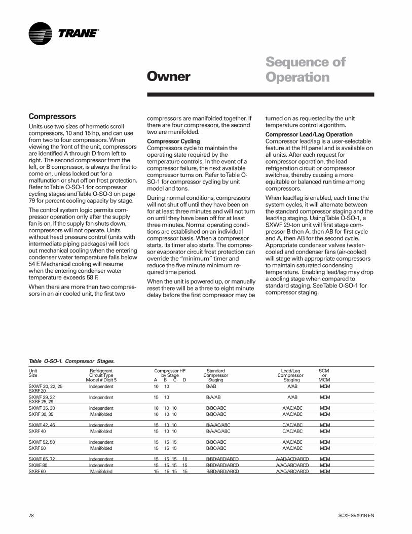
78 SCXF-SVX01B-EN
Table O-SO-1. Compressor Stages.
Unit Refrigerant Compressor HP Standard Lead/Lag SCMSize Circuit Type by Stage Compressor Compressor or
Model # Digit 5 A B C D Staging Staging MCMSXWF 20, 22, 25 Independent 10 10 B/AB A/AB MCMSXRF 20SXWF 29, 32 Independent 15 10 B/A/AB A/AB MCMSXRF 25, 29SXWF 35, 38 Independent 10 10 10 B/BC/ABC A/AC/ABC MCMSXRF 30, 35 Manifolded 10 10 10 B/BC/ABC A/AC/ABC MCM
SXWF 42, 46 Independent 15 10 10 B/A/AC/ABC C/AC/ABC MCMSXRF 40 Manifolded 15 10 10 B/A/AC/ABC C/AC/ABC MCM
SXWF 52, 58 Independent 15 15 15 B/BC/ABC A/AC/ABC MCMSXRF 50 Manifolded 15 15 15 B/BC/ABC A/AC/ABC MCM
SXWF 65, 72 Independent 15 15 15 10 B/BD/ABD/ABCD A/AD/ACD/ABCD MCMSXWF 80 Independent 15 15 15 15 B/BD/ABD/ABCD A/AC/ABC/ABCD MCMSXRF 60 Manifolded 15 15 15 15 B/BD/ABD/ABCD A/AC/ABC/ABCD MCM
Owner
Compressors
Units use two sizes of hermetic scrollcompressors, 10 and 15 hp, and can usefrom two to four compressors. Whenviewing the front of the unit, compressorsare identified A through D from left toright. The second compressor from theleft, or B compressor, is always the first tocome on, unless locked out for amalfunction or shut off on frost protection.Refer to Table O-SO-1 for compressorcycling stages and Table O-SO-3 on page79 for percent cooling capacity by stage.
The control system logic permits com-pressor operation only after the supplyfan is on. If the supply fan shuts down,compressors will not operate. Unitswithout head pressure control (units withintermediate piping packages) will lockout mechanical cooling when the enteringcondenser water temperature falls below54 F. Mechanical cooling will resumewhen the entering condenser watertemperature exceeds 58 F.
When there are more than two compres-sors in an air cooled unit, the first two
Sequence ofOperation
compressors are manifolded together. Ifthere are four compressors, the secondtwo are manifolded.
Compressor CyclingCompressors cycle to maintain theoperating state required by thetemperature controls. In the event of acompressor failure, the next availablecompressor turns on. Refer to Table O-SO-1 for compressor cycling by unitmodel and tons.
During normal conditions, compressorswill not shut off until they have been onfor at least three minutes and will not turnon until they have been off for at leastthree minutes. Normal operating condi-tions are established on an individualcompressor basis. When a compressorstarts, its timer also starts. The compres-sor evaporator circuit frost protection canoverride the “minimum” timer andreduce the five minute minimum re-quired time period.
When the unit is powered up, or manuallyreset there will be a three to eight minutedelay before the first compressor may be
turned on as requested by the unittemperature control algorithm.
Compressor Lead/Lag OperationCompressor lead/lag is a user-selectablefeature at the HI panel and is available onall units. After each request forcompressor operation, the leadrefrigeration circuit or compressorswitches, thereby causing a moreequitable or balanced run time amongcompressors.
When lead/lag is enabled, each time thesystem cycles, it will alternate betweenthe standard compressor staging and thelead/lag staging. Using Table O-SO-1, aSXWF 29-ton unit will first stage com-pressor B then A, then AB for first cycleand A, then AB for the second cycle.Appropriate condenser valves (water-cooled and condenser fans (air-cooled)will stage with appropriate compressorsto maintain saturated condensingtemperature. Enabling lead/lag may dropa cooling stage when compared tostandard staging. See Table O-SO-1 forcompressor staging.
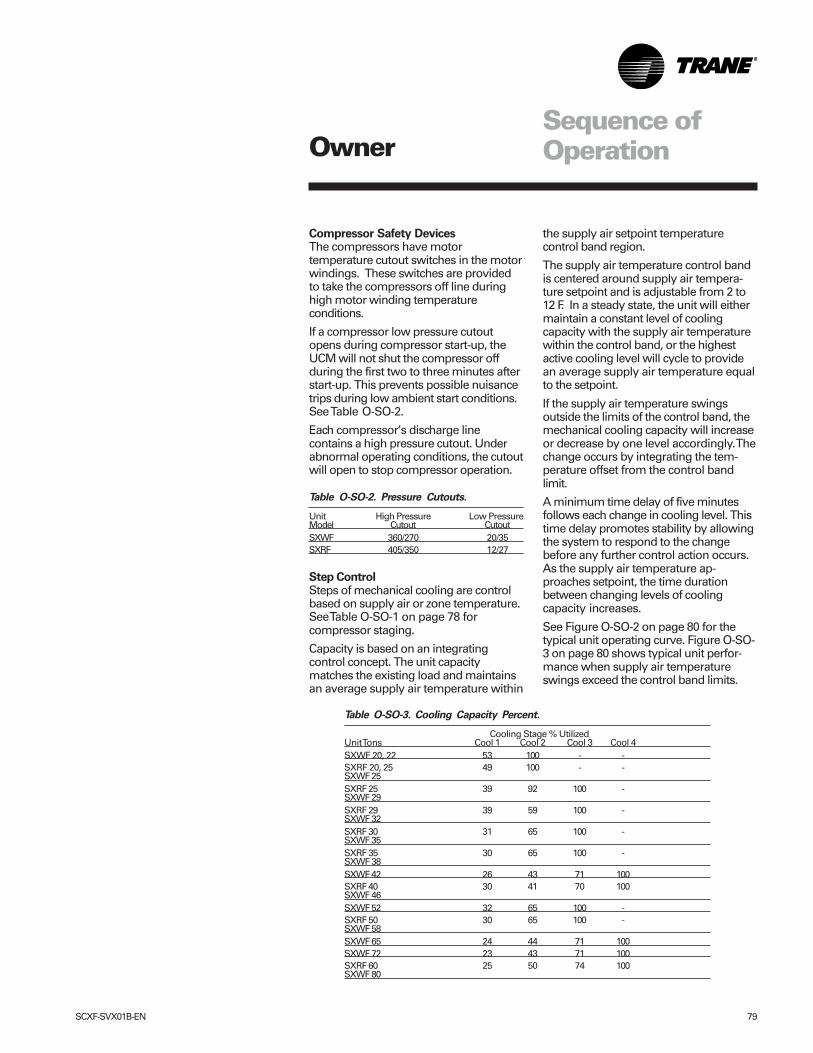
SCXF-SVX01B-EN 79
OwnerSequence ofOperation
Compressor Safety DevicesThe compressors have motortemperature cutout switches in the motorwindings. These switches are providedto take the compressors off line duringhigh motor winding temperatureconditions.
If a compressor low pressure cutoutopens during compressor start-up, theUCM will not shut the compressor offduring the first two to three minutes afterstart-up. This prevents possible nuisancetrips during low ambient start conditions.See Table O-SO-2.
Each compressor’s discharge linecontains a high pressure cutout. Underabnormal operating conditions, the cutoutwill open to stop compressor operation.
Table O-SO-2. Pressure Cutouts.
Unit High Pressure Low PressureModel Cutout CutoutSXWF 360/270 20/35SXRF 405/350 12/27
Step ControlSteps of mechanical cooling are controlbased on supply air or zone temperature.See Table O-SO-1 on page 78 forcompressor staging.
Capacity is based on an integratingcontrol concept. The unit capacitymatches the existing load and maintainsan average supply air temperature within
the supply air setpoint temperaturecontrol band region.
The supply air temperature control bandis centered around supply air tempera-ture setpoint and is adjustable from 2 to12 F. In a steady state, the unit will eithermaintain a constant level of coolingcapacity with the supply air temperaturewithin the control band, or the highestactive cooling level will cycle to providean average supply air temperature equalto the setpoint.
If the supply air temperature swingsoutside the limits of the control band, themechanical cooling capacity will increaseor decrease by one level accordingly. Thechange occurs by integrating the tem-perature offset from the control bandlimit.
A minimum time delay of five minutesfollows each change in cooling level. Thistime delay promotes stability by allowingthe system to respond to the changebefore any further control action occurs.As the supply air temperature ap-proaches setpoint, the time durationbetween changing levels of coolingcapacity increases.
See Figure O-SO-2 on page 80 for thetypical unit operating curve. Figure O-SO-3 on page 80 shows typical unit perfor-mance when supply air temperatureswings exceed the control band limits.
Table O-SO-3. Cooling Capacity Percent.
Cooling Stage % UtilizedUnit Tons Cool 1 Cool 2 Cool 3 Cool 4SXWF 20, 22 53 100 - -SXRF 20, 25 49 100 - -SXWF 25SXRF 25 39 92 100 -SXWF 29SXRF 29 39 59 100 -SXWF 32SXRF 30 31 65 100 -SXWF 35SXRF 35 30 65 100 -SXWF 38SXWF 42 26 43 71 100SXRF 40 30 41 70 100SXWF 46SXWF 52 32 65 100 -SXRF 50 30 65 100 -SXWF 58SXWF 65 24 44 71 100SXWF 72 23 43 71 100SXRF 60 25 50 74 100SXWF 80
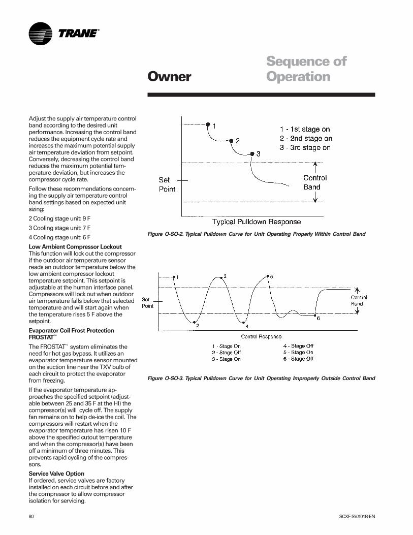
80 SCXF-SVX01B-EN
OwnerSequence ofOperation
Figure O-SO-2. Typical Pulldown Curve for Unit Operating Properly Within Control Band
Figure O-SO-3. Typical Pulldown Curve for Unit Operating Improperly Outside Control Band
Adjust the supply air temperature controlband according to the desired unitperformance. Increasing the control bandreduces the equipment cycle rate andincreases the maximum potential supplyair temperature deviation from setpoint.Conversely, decreasing the control bandreduces the maximum potential tem-perature deviation, but increases thecompressor cycle rate.
Follow these recommendations concern-ing the supply air temperature controlband settings based on expected unitsizing:
2 Cooling stage unit: 9 F
3 Cooling stage unit: 7 F
4 Cooling stage unit: 6 F
Low Ambient Compressor LockoutThis function will lock out the compressorif the outdoor air temperature sensorreads an outdoor temperature below thelow ambient compressor lockouttemperature setpoint. This setpoint isadjustable at the human interface panel.Compressors will lock out when outdoorair temperature falls below that selectedtemperature and will start again whenthe temperature rises 5 F above thesetpoint.
Evaporator Coil Frost ProtectionFROSTAT™
The FROSTAT™ system eliminates theneed for hot gas bypass. It utilizes anevaporator temperature sensor mountedon the suction line near the TXV bulb ofeach circuit to protect the evaporatorfrom freezing.
If the evaporator temperature ap-proaches the specified setpoint (adjust-able between 25 and 35 F at the HI) thecompressor(s) will cycle off. The supplyfan remains on to help de-ice the coil. Thecompressors will restart when theevaporator temperature has risen 10 Fabove the specified cutout temperatureand when the compressor(s) have beenoff a minimum of three minutes. Thisprevents rapid cycling of the compres-sors.
Service Valve OptionIf ordered, service valves are factoryinstalled on each circuit before and afterthe compressor to allow compressorisolation for servicing.
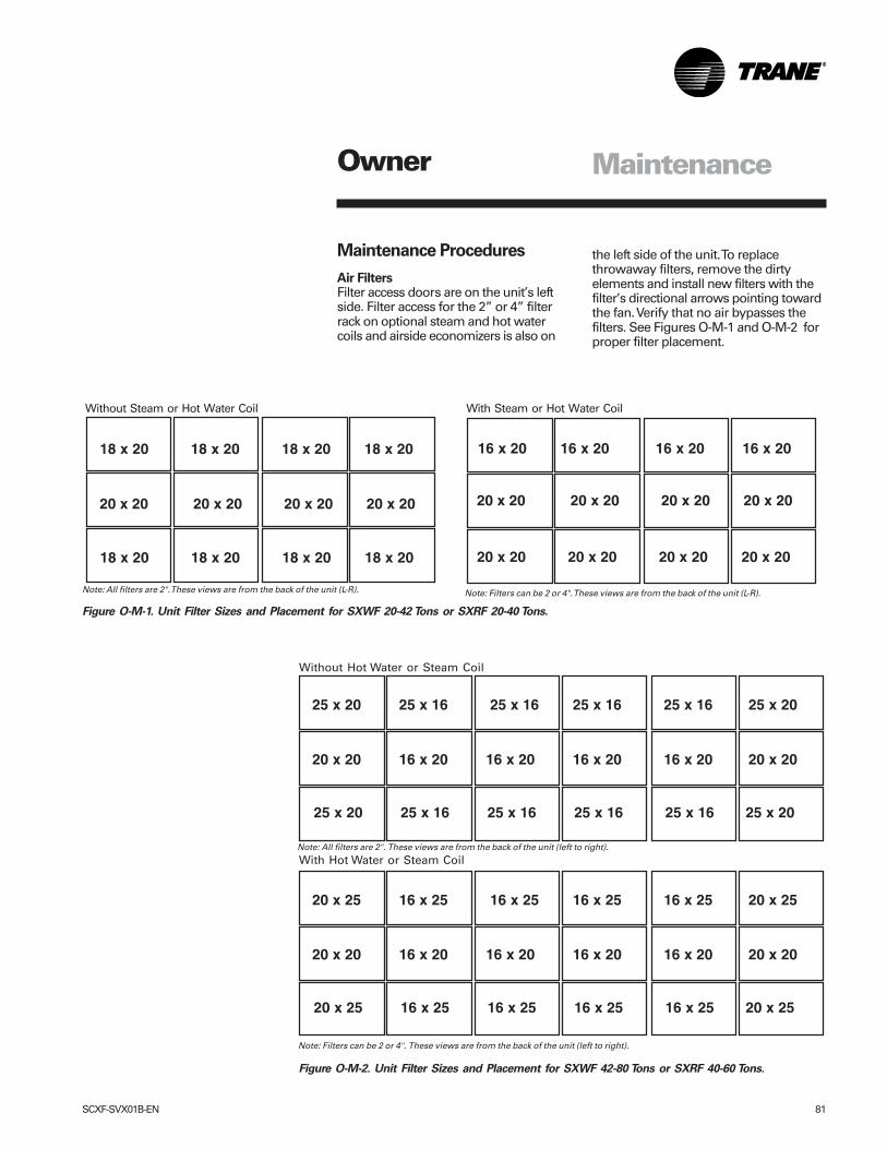
SCXF-SVX01B-EN 81
Owner
Maintenance Procedures
Air FiltersFilter access doors are on the unit’s leftside. Filter access for the 2” or 4” filterrack on optional steam and hot watercoils and airside economizers is also on
Figure O-M-1. Unit Filter Sizes and Placement for SXWF 20-42 Tons or SXRF 20-40 Tons.
Without Steam or Hot Water Coil With Steam or Hot Water Coil
Note: Filters can be 2 or 4". These views are from the back of the unit (L-R).Note: All filters are 2". These views are from the back of the unit (L-R).
18 x 20 18 x 20 18 x 20 18 x 20
20 x 20 20 x 20 20 x 20 20 x 20
18 x 20 18 x 20 18 x 20 18 x 20
16 x 20 16 x 20 16 x 20 16 x 20
20 x 20 20 x 20 20 x 20 20 x 20
20 x 20 20 x 20 20 x 20 20 x 20
Without Hot Water or Steam Coil
Note: Filters can be 2 or 4". These views are from the back of the unit (left to right).
With Hot Water or Steam CoilNote: All filters are 2". These views are from the back of the unit (left to right).
25 x 20 25 x 16 25 x 16 25 x 16 25 x 16 25 x 20
20 x 20 16 x 20 16 x 20 16 x 20 16 x 20 20 x 20
25 x 20 25 x 16 25 x 16 25 x 16 25 x 16 25 x 20
20 x 25 16 x 25 16 x 25 16 x 25 16 x 25 20 x 25
20 x 20 16 x 20 16 x 20 16 x 20 16 x 20 20 x 20
20 x 25 16 x 25 16 x 25 16 x 25 16 x 25 20 x 25
the left side of the unit. To replacethrowaway filters, remove the dirtyelements and install new filters with thefilter’s directional arrows pointing towardthe fan. Verify that no air bypasses thefilters. See Figures O-M-1 and O-M-2 forproper filter placement.
Maintenance
Figure O-M-2. Unit Filter Sizes and Placement for SXWF 42-80 Tons or SXRF 40-60 Tons.
82 SCXF-SVX01B-EN
Inspecting and Cleaning theDrain Pan
Check the condensate drain pan anddrain line to ensure that the condensatedrains properly at least every six monthsor as dictated by operating experience.
If evidence of standing water orcondensate overflow exists, take steps toidentify and remedy the causeimmediately. Refer to the troubleshooting section of this manual forpossible causes and solutions. If microbialgrowth is evident in the drain pan,remove and clean it immediately. Cleandrain pans using the following procedure:
1. Disconnect all electrical power to theunit.
2. Don the appropriate personalprotective equipment (PPE).
3. Remove all standing water.4. Use a scraper or other tools to remove
and solid matter. Remove solid matterwith a vacuum device that utilizes highefficiency particulate arrestance (HEPA)filters with a minimum efficiency of99.97% at 0.3 micron particle size.
5. Thoroughly clean the contaminatedarea(s) with a mild bleach and watersolution or an EPA-approved sanitizerspecifically designed for HVAC use.Carefully follow the sanitizermanufacturer’s instructions regardingproduct use.
6. Immediately rinse the drain panthoroughly with fresh water to preventpotential corrosion from the cleaningsolution.
7. Allow the unit to dry thoroughly beforeputting the system back into service.
8. Determine and correct the cause ofany microbial contamination.
9. Be careful that the contaminatedmaterial does not contact other areas ofthe unit or building. Properly dispose ofall contaminated materials and cleaningsolution.
Note: Standing water in drain pans canpromote microbial growth (mold) whichmay cause unpleasant odors and serioushealth-related indoor air quality problems. Ifmicrobial growth is found, it must beremoved immediately and that portion ofthe unit properly cleaned and sanitized.
Inspecting and Cleaning theFan
Inspect the fan section every six monthsor more frequently if operatingexperience dictates. Clean accumulateddirt and organic matter on the fan interiorsurfaces following the procedure below:
1. Disconnect all electrical power to theunit.
2. Don the appropriate personalprotective equipment (PPE).
3. Use a portable vacuum with HEPAfiltration to remove the loose dirt andorganic matter. The filter should be99.97% efficient at 0.3 micron particlesize.
4. If no microbial growth (mold) exists,thoroughly clean the fan and associatedcomponents with an industrial cleaningsolution. Carefully follow the cleaningsolution manufacturer’s instructionsregarding personal protection andventilation when using their product.
5. If microbial growth is present, removethe contamination (Step 2) andthoroughly clean the affected area withan EPA-approved sanitizer specificallydesigned for HVAC use. Carefully followthe sanitizer manufacturer’s instructionsregarding the product usage.
6. Rinse the affected surfaces thoroughlywith fresh water and a fresh sponge toprevent potential corrosion of metalsurfaces.
7. Allow the unit to dry completely beforeputting it back into service.
8. Ensure that contaminated materialdoes not contact other areas of the unitor building. Properly dispose of allcontaminated materials and cleaningsolution.
Determine the cause of any microbialgrowth (mold) and take action to ensure itdoes not reoccur.
Owner Maintenace
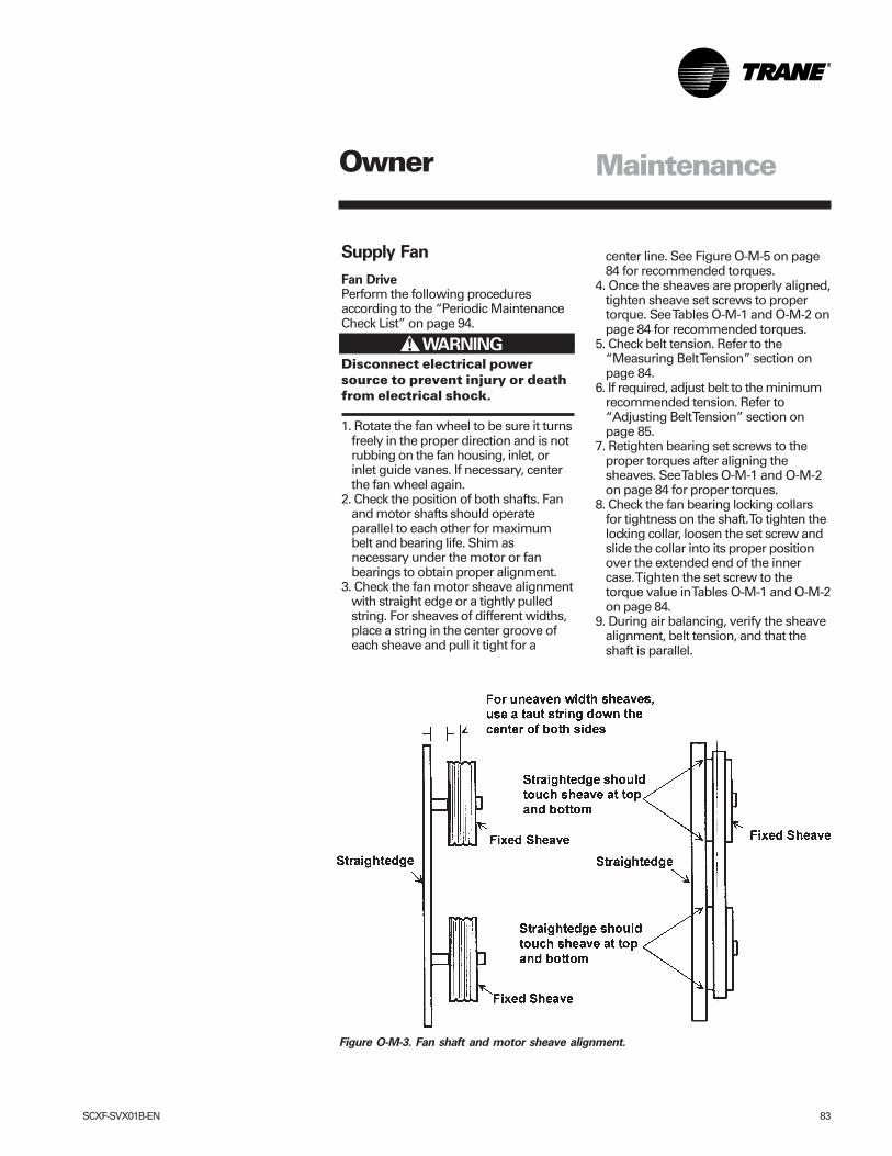
SCXF-SVX01B-EN 83
Supply Fan
Fan DrivePerform the following proceduresaccording to the “Periodic MaintenanceCheck List” on page 94.
Disconnect electrical powersource to prevent injury or deathfrom electrical shock.
1. Rotate the fan wheel to be sure it turnsfreely in the proper direction and is notrubbing on the fan housing, inlet, orinlet guide vanes. If necessary, centerthe fan wheel again.
2. Check the position of both shafts. Fanand motor shafts should operateparallel to each other for maximumbelt and bearing life. Shim asnecessary under the motor or fanbearings to obtain proper alignment.
3. Check the fan motor sheave alignmentwith straight edge or a tightly pulledstring. For sheaves of different widths,place a string in the center groove ofeach sheave and pull it tight for a
! WARNING
center line. See Figure O-M-5 on page84 for recommended torques.
4. Once the sheaves are properly aligned,tighten sheave set screws to propertorque. See Tables O-M-1 and O-M-2 onpage 84 for recommended torques.
5. Check belt tension. Refer to the“Measuring Belt Tension” section onpage 84.
6. If required, adjust belt to the minimumrecommended tension. Refer to“Adjusting Belt Tension” section onpage 85.
7. Retighten bearing set screws to theproper torques after aligning thesheaves. See Tables O-M-1 and O-M-2on page 84 for proper torques.
8. Check the fan bearing locking collarsfor tightness on the shaft. To tighten thelocking collar, loosen the set screw andslide the collar into its proper positionover the extended end of the innercase. Tighten the set screw to thetorque value in Tables O-M-1 and O-M-2on page 84.
9. During air balancing, verify the sheavealignment, belt tension, and that theshaft is parallel.
Figure O-M-3. Fan shaft and motor sheave alignment.
Owner Maintenance
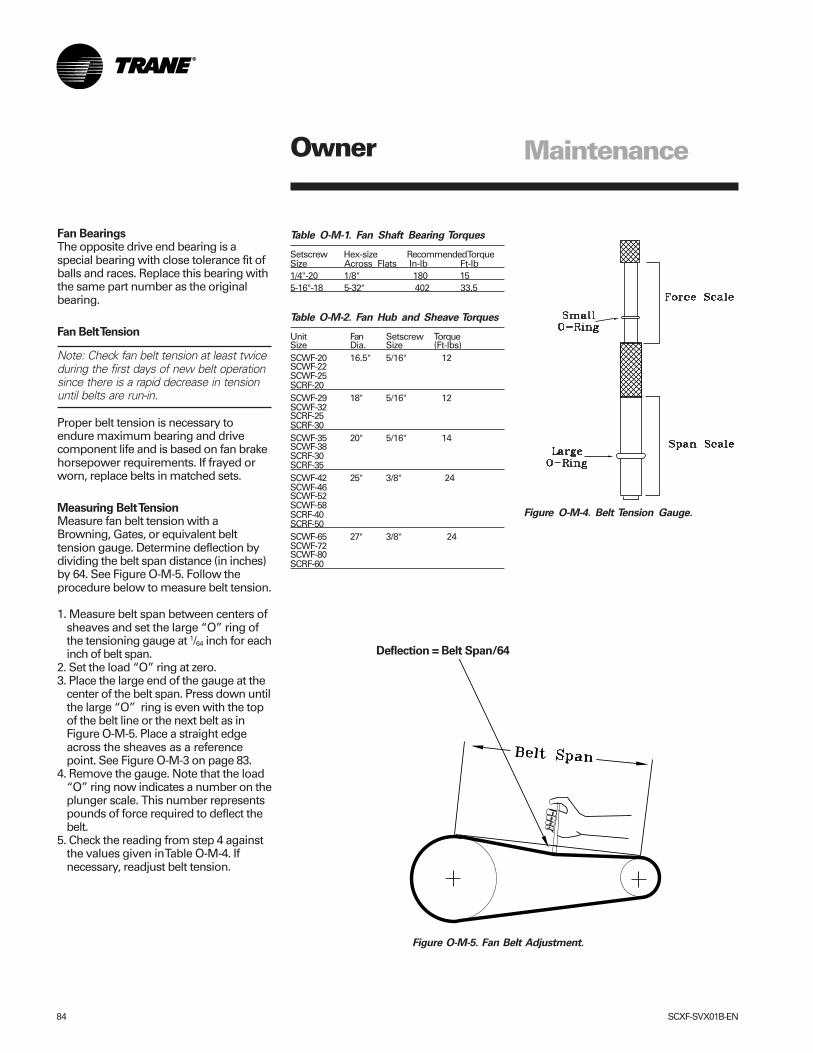
84 SCXF-SVX01B-EN
Table O-M-1. Fan Shaft Bearing Torques
Setscrew Hex-size Recommended TorqueSize Across Flats In-lb Ft-lb1/4"-20 1/8" 180 155-16"-18 5-32" 402 33.5
Table O-M-2. Fan Hub and Sheave Torques
Unit Fan Setscrew TorqueSize Dia. Size (Ft-lbs)SCWF-20 16.5" 5/16" 12SCWF-22SCWF-25SCRF-20SCWF-29 18" 5/16" 12SCWF-32SCRF-25SCRF-30SCWF-35 20" 5/16" 14SCWF-38SCRF-30SCRF-35SCWF-42 25" 3/8" 24SCWF-46SCWF-52SCWF-58SCRF-40SCRF-50SCWF-65 27" 3/8" 24SCWF-72SCWF-80SCRF-60
Figure O-M-5. Fan Belt Adjustment.
Figure O-M-4. Belt Tension Gauge.
Fan BearingsThe opposite drive end bearing is aspecial bearing with close tolerance fit ofballs and races. Replace this bearing withthe same part number as the originalbearing.
Fan Belt Tension
Note: Check fan belt tension at least twiceduring the first days of new belt operationsince there is a rapid decrease in tensionuntil belts are run-in.
Proper belt tension is necessary toendure maximum bearing and drivecomponent life and is based on fan brakehorsepower requirements. If frayed orworn, replace belts in matched sets.
Measuring Belt TensionMeasure fan belt tension with aBrowning, Gates, or equivalent belttension gauge. Determine deflection bydividing the belt span distance (in inches)by 64. See Figure O-M-5. Follow theprocedure below to measure belt tension.
1. Measure belt span between centers ofsheaves and set the large “O” ring ofthe tensioning gauge at 1/64 inch for eachinch of belt span.
2. Set the load “O” ring at zero.3. Place the large end of the gauge at the
center of the belt span. Press down untilthe large “O” ring is even with the topof the belt line or the next belt as inFigure O-M-5. Place a straight edgeacross the sheaves as a referencepoint. See Figure O-M-3 on page 83.
4. Remove the gauge. Note that the load“O” ring now indicates a number on theplunger scale. This number representspounds of force required to deflect thebelt.
5. Check the reading from step 4 againstthe values given in Table O-M-4. Ifnecessary, readjust belt tension.
Deflection = Belt Span/64
Owner Maintenance
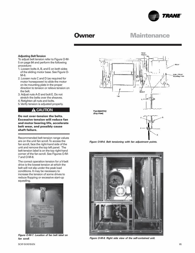
SCXF-SVX01B-EN 85
Adjusting Belt TensionTo adjust belt tension refer to Figure O-M-5 on page 84 and perform the followingprocedure:1. Loosen bolts A, B, and E on both sides
of the sliding motor base. See Figure O-M-6.
2. Loosen nuts C and D (as required formotor horsepower) to slide the motoron its mounting plate in the properdirection to tension or relieve tension onthe belt.
3. Adjust nuts A-D and bolt E. Do notstretch the belts over the sheaves.
4. Retighten all nuts and bolts.5. Verify tension is adjusted properly.
Do not over-tension the belts.Excessive tension will reduce fanand motor bearing life, acceleratebelt wear, and possibly causeshaft failure.
Recommended belt tension range valuesare on the unit fan scroll. To access thefan scroll, face the right-hand side of theunit and remove the top left panel. Thebelt tension label is on the top right-handcorner of the fan scroll. See Figures O-M-7 and O-M-8.
The correct operation tension for a V-beltdrive is the lowest tension at which thebelt will not slip under the peak loadconditions. It may be necessary toincrease the tension of some drives toreduce flopping or excessive start-upsquealing.
Figure O-M-6. Belt tensioning with fan adjustment points.
Figure O-M-7. Location of fan belt label on
fan scroll. Figure O-M-8. Right side view of the self-contained unit.
CAUTION!
Owner Maintenance
86 SCXF-SVX01B-EN
Follow specific manufacturer’sguidelines for conversion of existingsystems.
• To assist in reducing power generationemissions, always attempt to improveequipment performance with improvedmaintenance and operations that willhelp conserve energy resources.
WARNING: Do not work in aclosed area where refrigerant ornitrogen gases may be leaking. Asufficient quantity of vapors maybe present and cause injury.
WARNING: Do not use oxygen,acetylene, or air in place ofrefrigerant and dry nitrogen forleak testing. A violent explosionmay result causing injury ordeath.
WARNING: Always use a pressureregulator, valves, and gauges tocontrol drum and line pressureswhen pressure testing thesystem. Excessive pressures maycause line ruptures, equipmentdamage, or an explosion whichmay result in injury or death.
WARNING: Do not exceed 200psig when leak testing thesystem. Damage to the unit couldresult, or an explosion may occurcausing injury or death
In the event of required system repair,leak test the liquid line, evaporator coil,and suction line at pressures dictated bylocal codes, and using the followingguidelines.
Owner
����� WARNING!
����� WARNING!
����� WARNING!
����� WARNING!
Maintenance
Refrigerant System
Special Note on Refrigerant EmissionsFollow the Trane recommendedprocedures on operation, maintenance,and service to ensure refrigerantconservation and emission reduction.Also, pay specific attention to thefollowing:• Whenever removing refrigerant from
air conditioning or refrigeratingequipment, recover for reuse, recycle,reprocess (reclaim), or properlydestroy it.
• Always determine possible refrigerantrecycling or reclaiming requirementsbefore beginning recovery. Questionsabout recovered refrigerants andacceptable refrigerant qualitystandards are addressed in ARIStandard 700.
• Use approved containment vesselsand safety standards. Comply with allapplicable transportation standardswhen shipping refrigerant containers.
• To minimize emissions whilerecovering refrigerant, use recyclingequipment. Always attempt to usemethods which will pull the lowestpossible system vacuum whilerecovering and condensing refrigerantinto containment.
• When leak checking with tracerefrigerant and nitrogen, use HCFC22(R22) rather than CFC12 (R12) or anyother fully halogenated refrigerants.Be aware of any new leak testmethods which eliminate refrigerantas a trace gas.
• When cleaning system components orparts, do not use CFC11 (R11) orCFC113 (R113). Refrigeration systemclean up methods using filters anddryers are recommended. Do not usesolvents which have ozone depletionfactors. Properly dispose of usedmaterials.
• Take extra care to properly maintain allservice equipment directly supportingrefrigerant service work such asgauges, hoses, vacuum pumps, andrecycling equipment.
• Stay aware of unit enhancements,conversion refrigerants, compatibleparts, and manufacturer’srecommendations that will reducerefrigerant emissions and increaseequipment operating efficiencies.
SCXF-SVX01B-EN 87
service equipment directly supportingrefrigerant service work such asgauges, hoses, vacuum pumps, andrecycling equipment.
• Stay aware of unit enhancements,conversion refrigerants, compatibleparts, and manufacturer’srecommendations that will reducerefrigerant emissions and increaseequipment operating efficiencies.Follow specific manufacturer’sguidelines for conversion of existingsystems.
• To assist in reducing power generationemissions, always attempt to improveequipment performance with improvedmaintenance and operations that willhelp conserve energy resources.
Refrigerant Leak Testing
Do not work in a closed areawhere refrigerant or nitrogengases may be leaking. Asufficient quantity of vapors maybe present and cause injury ordeath.
Do not use oxygen, acetylene, orair in place of refrigerant and drynitrogen for leak testing. Aviolent explosion may resultcausing injury or death.
Always use a pressure regulator,valves, and gauges to controldrum and line pressures whenpressure testing the system.Excessive pressures may causeline ruptures, equipment damage,or an explosion which may resultin injury or death.
compressors running.
Caution: Do not operate thecompressors without somerefrigerant in each circuit. Failureto do so may damage thecompressors.
Charge refrigerant into the system byRefrigerant System
Special Note on Refrigerant EmissionsFollow the Trane recommendedprocedures on operation, maintenance,and service to endure refrigerantconservation and emission reduction.Also, pay specific attention to thefollowing:• When removing refrigerant from air
conditioning or refrigerating equipmentrecover for reuse, recycling,reprocessing (reclaim), or properlydestroy it.
• Always determine possible refrigerantrecycling or reclaiming requirementsbefore beginning recovery. Questionsabout recovered refrigerants andacceptable refrigerant qualitystandards are addressed in ARIStandard 700.
• Use approved containment vessels andsafety standards when shippingrefrigerant containers.
• To minimize emissions while recoveringrefrigerant, use recycling equipment.Always attempt to use methods thatwill pull the lowest possible systemvacuum while recovering andcondensing refrigerant intocontainment.
• When leak checking with tracerefrigerant and nitrogen, use HCFC22(R22) rather than CFC12 (R12) or anyother fully halogenated refrigerants. Beaware of any new leak test methodswhich eliminate refrigerant as a tracegas.
• When cleaning system components orparts, do not use CFC11 (R11) or CFC113 (R113). Refrigeration system clean-up methods using filters and dryers arerecommended. Do not use solventswhich have ozone depletion factors.Properly dispose of used materials.
• Take extra care to properly maintain all
Owner Maintenance
1. Charge enough refrigerant and drynitrogen into the system to raise thepressure to 100 psig.
2. Use a halogen leak detector, halidetorch, or soap bubbles to check forleaks. Check interconnecting pipingjoints, the evaporator coil connections,and all accessory connections.
3. If a leak is detected, release the testpressure, break the connections andreassemble it as a new joint, usingproper brazing techniques.
4. If no leak is detected, use nitrogen toincrease the test pressure to 150 psigand repeat the leak test. Also, use soapbubbles to check for leaks whennitrogen is added.
5. Retest the system to make sure newconnections are solid.
6. If a leak is suspected after the systemhas been fully charged with refrigerant,use a halogen leak detector, halidetorch, or soap bubbles to check forleaks.
Refrigerant EvacuationFor field evacuation, use a rotary stylevacuum pump capable of pulling avacuum of 100 microns or less.
When connecting the vacuum pump to arefrigeration system, it is important tomanifold the pump to both the high andlow side of the system. Follow the pumpmanufacturer’s directions.
Do not use a Meg ohm meter orapply power to the winding of acompressor while it is under adeep vacuum. This may damagethe motor windings.
Refrigerant ChargingAfter leak testing and evacuating thesystem, charge liquid refrigerant into thesystem through the liquid line valve. Aftersome refrigerant has entered eachcircuit, charge gaseous refrigerant intothe suction line shrader valve with the
����� CAUTION!
����� CAUTION!
����� WARNING!
����� WARNING!
����� WARNING!
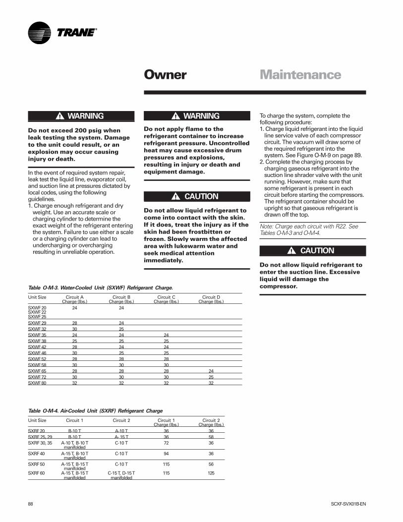
88 SCXF-SVX01B-EN
Do not exceed 200 psig whenleak testing the system. Damageto the unit could result, or anexplosion may occur causinginjury or death.
In the event of required system repair,leak test the liquid line, evaporator coil,and suction line at pressures dictated bylocal codes, using the followingguidelines.1. Charge enough refrigerant and dry
weight. Use an accurate scale orcharging cylinder to determine theexact weight of the refrigerant enteringthe system. Failure to use either a scaleor a charging cylinder can lead toundercharging or overchargingresulting in unreliable operation.
Owner Maintenance
����� WARNING!Do not apply flame to therefrigerant container to increaserefrigerant pressure. Uncontrolledheat may cause excessive drumpressures and explosions,resulting in injury or death andequipment damage.
Do not allow liquid refrigerant tocome into contact with the skin.If it does, treat the injury as if theskin had been frostbitten orfrozen. Slowly warm the affectedarea with lukewarm water andseek medical attentionimmediately.
To charge the system, complete thefollowing procedure:1. Charge liquid refrigerant into the liquid
line service valve of each compressorcircuit. The vacuum will draw some ofthe required refrigerant into thesystem. See Figure O-M-9 on page 89.
2. Complete the charging process bycharging gaseous refrigerant into thesuction line shrader valve with the unitrunning. However, make sure thatsome refrigerant is present in eachcircuit before starting the compressors.The refrigerant container should beupright so that gaseous refrigerant isdrawn off the top.
Note: Charge each circuit with R22. SeeTables O-M-3 and O-M-4.
Do not allow liquid refrigerant toenter the suction line. Excessiveliquid will damage thecompressor.
����� WARNING!
����� CAUTION!
����� CAUTION!
Table O-M-3. Water-Cooled Unit (SXWF) Refrigerant Charge.
Unit Size Circuit A Circuit B Circuit C Circuit DCharge (lbs.) Charge (lbs.) Charge (lbs.) Charge (lbs.)
SXWF 20 24 24SXWF 22SXWF 25SXWF 29 28 24SXWF 32 30 25SXWF 35 24 24 24SXWF 38 25 25 25SXWF 42 28 24 24SXWF 46 30 25 25SXWF 52 28 28 28SXWF 58 30 30 30SXWF 65 28 28 28 24SXWF 72 30 30 30 25SXWF 80 32 32 32 32
Table O-M-4. Air-Cooled Unit (SXRF) Refrigerant Charge
Unit Size Circuit 1 Circuit 2 Circuit 1 Circuit 2Charge (lbs.) Charge (lbs.)
SXRF 20 B-10 T A-10 T 36 36SXRF 25, 29 B-10 T A- 15 T 36 58SXRF 30, 35 A-10 T, B-10 T C-10 T 72 36
manifoldedSXRF 40 A-15 T, B-10 T C-10 T 94 36
manifoldedSXRF 50 A-15 T, B-15 T C-10 T 115 56
manifoldedSXRF 60 A-15 T, B-15 T C-15 T, D-15 T 115 125
manifolded manifolded
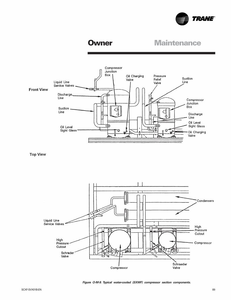
SCXF-SVX01B-EN 89
Figure O-M-9. Typical water-cooled (SXWF) compressor section components.
MaintenanceOwner
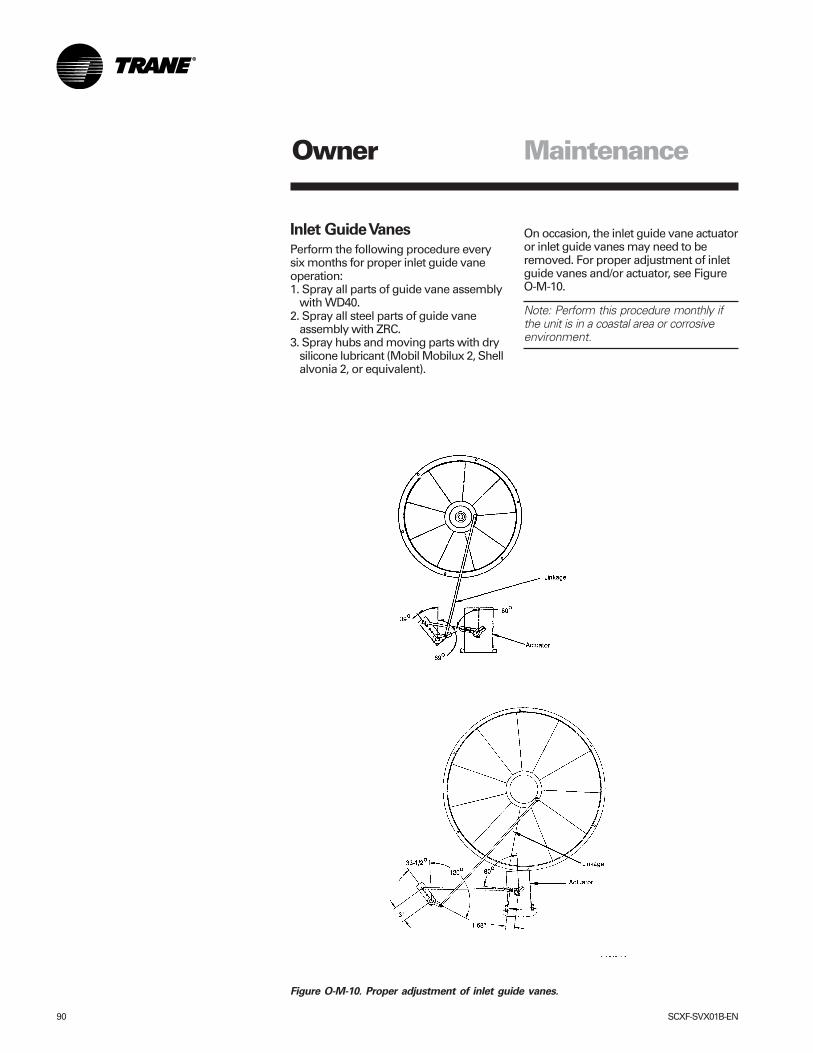
90 SCXF-SVX01B-EN
Inlet Guide Vanes
Perform the following procedure everysix months for proper inlet guide vaneoperation:1. Spray all parts of guide vane assembly
with WD40.2. Spray all steel parts of guide vane
assembly with ZRC.3. Spray hubs and moving parts with dry
silicone lubricant (Mobil Mobilux 2, Shellalvonia 2, or equivalent).
Maintenance
On occasion, the inlet guide vane actuatoror inlet guide vanes may need to beremoved. For proper adjustment of inletguide vanes and/or actuator, see FigureO-M-10.
Note: Perform this procedure monthly ifthe unit is in a coastal area or corrosiveenvironment.
Figure O-M-10. Proper adjustment of inlet guide vanes.
Owner
SCXF-SVX01B-EN 91
Coil Fin Cleaning
Keep coils clean to maintain maximumperformance. For operation at its highestefficiency, clean the refrigerant coil oftenduring periods of high cooling demand orwhen dirty conditions prevail. Clean thecoil a minimum of once per year toprevent dirt buildup in the coil fins, whereit may not be visible.
Remove large debris from the coils andstraighten fins before cleaning. Removefilters before cleaning.
Clean refrigerant coils with cold waterand detergent, or with one of the com-mercially available chemical coil clean-ers. Rinse coils thoroughly after cleaning.
Economizer and evaporator coils areinstalled so the evaporator is directlybehind the economizer. To clean betweenthe coils, remove the sheet metal blockoff. Access the block off by removing thecorner panels on the unit’s left or rightrear side.
Do not clean the refrigerant coilwith hot water or steam. The useof hot water or steam as arefrigerant coil-cleaner agent willcause high pressure inside thecoil tubing and subsequentdamage to the coil.
To prevent damage to the unit, donot use acidic chemical coilcleaners. Also, do not usealkaline chemical coil cleanerswith a pH value greater then 8.5(after mixing) without using analuminum corrosion inhibitor inthe cleaning solution.
Some chemical coil cleaningcompounds are caustic or toxic.Use these substances only inaccordance with themanufacturer’s instructions.Failure to do so may result ininjury, death, or equipmentdamage.
If the refrigerant coil is installed back toback with the waterside economizer coil,use a cleaner that is acceptable forcleaning both types of coils.
Inspecting and Cleaning CoilsCoils become externally fouled as a resultof normal operation. Dirt on the coilsurface reduces it’s ability to transfer heatthat can result in comfort problems,increased airflow resistance and thusincreased operating energy costs. If thecoil surface dirt becomes wet, whichcommonly occurs with cooling coils,microbial growth (mold) may result,causing unpleasant odors and serioushealth-related indoor air qualityproblems.
Inspect coils at least every six months ormore frequently as dictated by operatingexperience. Cleaning frequently isdependent upon system operating hours,filter maintenance, and efficiency and dirtload. Follow is the suggested methodbelow:
Steam and Hot Water Coils1. Disconnect all electrical power to the
unit.2. Don the appropriate personal
protective equipment (PPE).3. Gain access to both sides of the coil
section.4. Use a soft brush to remove loose
debris from both sides of the coil.5. Use a steam cleaning machine, starting
from the top of the coil and workingdownward. Clean the leaving air side ofthe coil first, then the entering air side.Use a block-off to prevent steam fromblowing through the coil and into a drysection of the unit.
6. Repeat step 5 as necessary. Confirmthat the drain line is open followingcompletion of the cleaning process.
7. Allow the unit to dry thoroughly beforeputting the system back into service.
8. Straighten any coil fins that may bedamaged with a fin rake.
9. Replace all panels and parts andrestore electrical power to the unit.
10. Ensure that contaminated materialdoes not contact other areas of the unitor building. Properly dispose of allcontaminated materials and cleaningsolutions.
Refrigerant Coils1. Disconnect all electrical power to the
unit.2. Don the appropriate personal
protective equipment (PPE).3. Gain access to the coil section of the
unit (both sides).4. Use a soft brush to remove loose
debris from both sides of the coil.5. Mix a high quality coil cleaning
detergent with water according to themanufacturer’s instructions. If thedetergent is strongly alkaline aftermixing (pH 8.5 or higher), it mustcontain an inhibitor. Carefully follow thecleaning solution manufacturer’sinstructions regarding product use.
6. Place the mixed solution in a gardenpump-up sprayer or high pressuresprayer. If using a high pressuresprayer note the following:
• Maintain a minimum nozzle sprayangle of 15 degrees
• Spray perpendicular to the coil face • Protect other areas of the unit and
internal controls from contact withmoisture or the cleaning solution
• Keep the nozzle at least 6 inches fromthe coil
• Do not exceed 600 psig
Draining the Coil
Failure to properly drain and ventcoils when not in use duringfreezing temperatures may resultin coil freeze-up damage.
Drain plugs are in the piping below eachcoil’s supply and return header. Use theseplugs to drain the coil and piping. Whendraining the coil, open the vents at the topof the supply and return headers.
Maintenance
����� CAUTION!
����� CAUTION!
����� WARNING!
����� CAUTION!
Owner
92 SCXF-SVX01B-EN
Maintenance
Also, a drain plug is at the bottom of theinlet condenser manifold and in the outletpipe near the unit’s left side. Removethese plugs to drain the condensers. Besure to open the vent plugs at the top ofthe condenser inlet and outlet manifold.See Figure O-M-9 on page 89.
When refilling the condenser/watersideeconomizer coil system with water,provide adequate water treatment toprevent the formation of scale orcorrosion.
Failure to provide adequate watertreatment in condenser systemsmay result in coil and condenserfouling or undue metal damage.
Cleaning the Condenser
Note: Using improperly treated or un-treated water in this equipment may resultin scaling, erosion, corrosion, algae, orslime. Engage the services of a qualifiedwater treatment specialist to determinewhat treatment is advisable. The TraneCompany warranty specifically excludesliability for corrosion, erosion, or deteriora-tion of Trane equipment. Trane assumesno responsibilities for the results of theuse of untreated or improperly treatedwater, saline, or brackish water.
Condensing water contains minerals thatcollect on the condenser tube walls.Cooling towers also collect dust andforeign materials that deposit in thecondenser tube. The formation of scale orsludge in the condenser is indicated by adecreased water flow, low temperaturedifference between inlet and outlet water,and abnormally high condensing tem-peratures. To maintain maximumcondenser efficiency, the condenser mustremain free of built-up scale and sludge.Clean the condenser either mechanicallyor chemically.
Mechanical Cleaning of Condenser andEconomizer Coils1. Turn off the condenser supply water.
Remove drain plugs discussed in the“Draining the Coil” section on page 91.
2. Remove the condenser’s left side to
expose the condenser tubes.3. Rotate a round brush through the tubes
to loosen contaminant.4. Flush tubes with water to push the
sludge out through the drain opening inthe bottom of the supply header andthe return pipe.
5. To clean the economizer tubes, removethe cast iron header plates at the coil’sright end between the inlet and outletheaders (4-row coils; 2-row coils do nothave cover plates at right end). Rotateround brush through tubes from leftend to loosen contaminants. Flushtubes with water.
6. Replace condenser end plates andclamps. The end plates must becentered when tightening the clamp.
7. Replace coil headers with gaskets andtorque bolts to 50 ft.-lb.
8. Replace drain and vent plugs.
Chemical Cleaning of Condenser andEconomizer CoilChemical cleaning removes scaledeposits built up by minerals in the water.For a suitable chemical solution, consult awater treatment specialist. Thecondenser water circuit is composed ofcopper, steel, and cast iron.
The chemical supply house shouldapprove or provide all materials used inthe external circulating system, alongwith the quantity of cleaning material,duration of cleaning time, and safetyprecautions necessary for handling thecleaning agent.
����� CAUTION!
Owner
SCXF-SVX01B-EN 93
Piping Components
Water ValvesWater valves have a stern packing nut. Ifthere is evidence of water leakage at thevalve stem, proceed as follows:1. Remove actuator motor from support
plate. (Remove four mount bolts)2. Remove shaft coupling.3. Torque the packing nut to 10-ft.-lbs. of
torque.4. Replace shaft coupling.5. Replace actuator motor (reinstall the
four mount bolts).
Note: If it is necessary to remove the fourvalve body bolts for valve cleaning orservice, torque to 45 ft-lb.
Flow Switch MaintenanceFlow switches have a magnet on thevane assembly that attracts ferrousparticulate may build up on the magnet tothe point that the vane will wedge so thatit will not operate.
When the flow switch does not operate,remove and replace it or disassembleand clean it.
Cleaning the Flow SwitchIf ferrous particulate contaminates towerwater, the ferrous particles will cling tothe magnet on the switch paddleassembly. A buildup of the ferrousparticles over a period os time will causethe paddle to stick and cease to functionproperly.
To avoid this problem, remove the switchand clean each time you clean thecondensers, or clean as needed to keepthe switch operational.
To clean the paddle assembly, remove itfollowing the procedure below:1. Remove the switch from the unit.2. The paddle assembly and wire retainer
Maintenance
clip holds the paddle assembly in theswitch body.
3. Remove the wire retainer clip byreaching down past the paddle with apair of slim nosed pliers and grippingthe end of the wire. Pull up on the wireclip and remove it.
4. After removing the wire clip, use thepliers to pull the paddle assembly out ofthe switch barrel. Clamp the pliers ontothe end of the paddle and remove thepaddle assembly. It will slide straightout.
5. Clean the ferrous particulate from themagnet using a rag or tack cloth. Theparticulate is attracted to the magnet,so it is necessary to pull it off. It will notsimply wipe off.
6. After cleaning the magnet, replace thepaddle assembly into the switch body’sbarrel. However, it is important toposition the paddle perpendicular to thearrow on the switch’s side and place thepaddle’s flat side facing the oppositedirection or the arrow. Push the paddleassembly in until it hits the barrel cavitybottom.
7. Place the spring clip into the switchbarrel and push it down with a small,flat blade screwdriver until the springclip engages the groove in the switchbarrel.
8. When replacing the paddle assembly,check the operation by pushing on thepaddle’s flat side. The paddle shouldswing freely in the direction of thearrow. This action confirms that thepaddle assembly is properly installed.
9. Replace the switch into the unit pipingusing a good pipe thread sealer. Tightenthe switch so that its final position hasthe arrow parallel to the water pipe andpointing toward the left end of the unit(arrow is pointing in the direction of thewater flow).
Owner
94 SCXF-SVX01B-EN
Maintenance PeriodicChecklists
Monthly ChecklistThe following check list provides therecommended maintenance schedule tokeep the unit running efficiently.
Disconnect power source andallow all rotating equipment tostop completely before servicingor inspecting the unit. Failure todo so may result in injury ordeath.
1. Inspect unit air filters. Clean or replaceif airflow is blocked or if filters are dirty.
2. Inspect coils for excess moisture oricing. Icing on the coils may indicate lowairflow supply, restricted airflow fromdirty fins, evaporator frost protectionsensor problems, or a shortage ofrefrigerant flowing through the coil.
3. Check that condensate from theevaporator and economizer coils flowsfreely through the condensate piping,traps, drain pan, and drainage holes.Remove algae and or any airflowobstructions.
4. Check the condition and tension of fanbelts. Adjust tension if belts are floppyor squeal continually. Replace worn orfraying belts in matched sets.
Note: Check and adjust belt tension atleast twice daily the first days of new beltoperation. Belt tension will rapidly de-crease until the belts are run in.
Maintenance
5. Check the liquid line sight glassesduring operation. Bubbles in the sightglasses indicate a possible shortage ofrefrigerant or an obstruction in theliquid lines, e.g. dirty liquid line filterdriers.
6. Inspect filter driers for leaks, flowobstructions, or temperature dropacross the filter drier. A noticeabletemperature differential, e.g. 5 F, in theliquid line may indicate an obstruction.Replace the filter drier if it appearsclogged.
7. Inspect the optional watersideeconomizer coil. Clean the coil toprevent airflow restrictions through thefins.
8. Check and record operating pressures.
Semi-Annual Maintenance1. Verify the fan motor is properly
lubricated. Follow lubricationrecommendations on the motor tag ornameplate. Contact the motormanufacturer for more information.
2. Lubricate fan bearings. For best results,lubricate bearings during unit operation.Refer to the “Fan Bearings” section onpage 84.
3. With power disconnected, manuallyrotate the fan wheel to check forobstructions in the housing orinterference with fan blades or inletguide vane option. Removeobstructions and debris. Center the fanwheel if necessary.
4. Check the fan assembly sheavealignment. Tighten set screws to theirproper torques.
5. Check water valves for leakage atvalve stem packing nut.
6. Inspect the inlet vane assembly andperform maintenance procedures inthe IGV maintenance section on page90.
Note: Perform this procedure monthly ifthe unit is in a coastal or corrosive environ-ment.
Annual MaintenanceCheck and tighten all set screws, bolts,locking collars and sheaves.1. Inspect, clean, and tighten all electrical
connections.2. Visually inspect the entire unit casing
for chips or corrosion. Remove rust orcorrosion and repaint surfaces.
3. Visually check for leaks in refrigerantpiping.
4. Inspect fan, motor, and control contacts.Replace badly worn or eroded contacts.
5. Inspect the thermal expansion valvesensing bulbs for cleanliness, goodcontact with the suction line, andadequate insulation from ambient air.
6. Verify the superheat setting is between12 and 17 F at the compressor.
When checking operating pressures andconditions, establish the followingnominal conditions for consistent mea-surements.1. Leaving air temperature greater than
60 F2. Entering air temperature between 80
and 90 F3. Entering water temperature greater
than 65 F4. Inlet vanes at least halfway open5. Compressors running at full load6. Drain the condensing water system
and inspect it thoroughly for fouling.Clean the condensers if necessary.
����� WARNING!
Owner
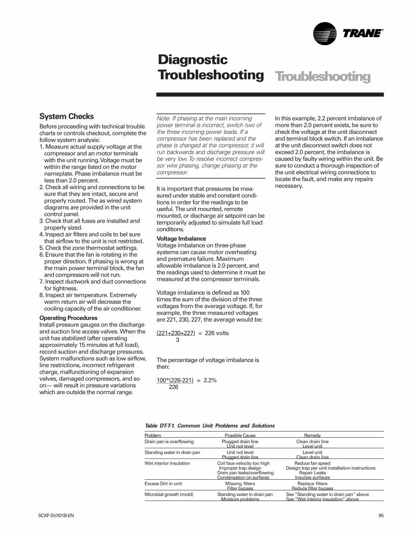
SCXF-SVX01B-EN 95
Table DT-T-1. Common Unit Problems and Solutions
Problem Possible Cause RemedyDrain pan is overflowing Plugged drain line Clean drain line
Unit not level Level unitStanding water in drain pan Unit not level Level unit
Plugged drain line Clean drain lineWet interior insulation Coil face velocity too high Reduce fan speed
Improper trap design Design trap per unit installation instructionsDrain pan leaks/overflowing Repair LeaksCondensation on surfaces Insulate surfaces
Excess Dirt in unit Missing filters Replace filtersFilter bypass Reduce filter bypass
Microbial growth (mold) Standing water in drain pan See “Standing water in drain pan” aboveMoisture problems See “Wet interior insulation” above
System Checks
Before proceeding with technical troublecharts or controls checkout, complete thefollow system analysis:1. Measure actual supply voltage at the
compressor and an motor terminalswith the unit running. Voltage must bewithin the range listed on the motornameplate. Phase imbalance must beless than 2.0 percent.
2. Check all wiring and connections to besure that they are intact, secure andproperly routed. The as wired systemdiagrams are provided in the unitcontrol panel.
3. Check that all fuses are installed andproperly sized.
4. Inspect air filters and coils to bel surethat airflow to the unit is not restricted.
5. Check the zone thermostat settings.6. Ensure that the fan is rotating in the
proper direction. If phasing is wrong atthe main power terminal block, the fanand compressors will not run.
7. Inspect ductwork and duct connectionsfor tightness.
8. Inspect air temperature. Extremelywarm return air will decrease thecooling capacity of the air conditioner.
Operating ProceduresInstall pressure gauges on the dischargeand suction line access valves. When theunit has stabilized (after operatingapproximately 15 minutes at full load),record suction and discharge pressures.System malfunctions such as low airflow,line restrictions, incorrect refrigerantcharge, malfunctioning of expansionvalves, damaged compressors, and soon— will result in pressure variationswhich are outside the normal range.
DiagnosticTroubleshooting
Note: If phasing at the main incomingpower terminal is incorrect, switch two ofthe three incoming power leads. If acompressor has been replaced and thephase is changed at the compressor, it willrun backwards and discharge pressure willbe very low. To resolve incorrect compres-sor wire phasing, change phasing at thecompressor.
It is important that pressures be mea-sured under stable and constant condi-tions in order for the readings to beuseful. The unit mounted, remotemounted, or discharge air setpoint can betemporarily adjusted to simulate full loadconditions.
Voltage ImbalanceVoltage imbalance on three-phasesystems can cause motor overheatingand premature failure. Maximumallowable imbalance is 2.0 percent, andthe readings used to determine it must bemeasured at the compressor terminals.
Voltage imbalance is defined as 100times the sum of the division of the threevoltages from the average voltage. If, forexample, the three measured voltagesare 221, 230, 227, the average would be:
(221+230+227) = 226 volts 3
The percentage of voltage imbalance isthen:
100*(226-221) = 2.2% 226
In this example, 2.2 percent imbalance ofmore than 2.0 percent exists, be sure tocheck the voltage at the unit disconnectand terminal block switch. If an imbalanceat the unit disconnect switch does notexceed 2.0 percent, the imbalance iscaused by faulty wiring within the unit. Besure to conduct a thorough inspection ofthe unit electrical wiring connections tolocate the fault, and make any repairsnecessary.
Troubleshooting
96 SCXF-SVX01B-EN
DiagnosticTroubleshooting
Diagnostics
Refer to the IntelliPak® Self-ContainedProgramming Guide, PKG-SVP01B-EN,for specific unit programming andtroubleshooting information. In particular,reference the “Service Mode Menu” and“Diagnostic Menu”sections in theprogramming guide. Refer to thefollowing text for general diagnostic andtroubleshooting procedures. Commondiagnostics and troubleshootingprocedures follow below.
A
Auto Reset S/A Static Pressure LimitProblem: The supply air static pressurewent too high.
Reason for Diagnostic: The S/A staticpressure exceeded the S/A staticpressure limit setpoint for at least onesecond continuously.
UCM’s Reaction: A "supply air pressureshutdown" signal is sent to the followingfunctions:a. Compressor staging control,b. Economizer actuator control,c. Heat operation,d. Supply fan control,e. IGV/VFD control,f. Exhaust fan control,g. Exhaust actuator control
Reset Required: (PAR) An automatic resetoccurs after the IGV close. The supply fanis not allowed to restart for 15 secondsafter the diagnostic occurs. An auto resetwill also occur if the unit cycles out ofoccupied mode and back.
C
CO2 Sensor Failure
Problem: The VCM CO2 sensor inputsignal is out of range.
Check: Check field/unit wiring betweensensor and VCM.
Reason for Diagnostic: The unit is readinga signal that is out of range for the CO2sensor transducer input.
UCM’s Reaction: The CO2 reset functiondisables.
Reset Required: (PAR) An automatic resetoccurs after the CO2 sensor transducerinput receives a signal that is within rangefor ten continuous seconds.
Compressor Contactor Fail - Circuit 1, 2,3, or 4Problem: The compressor contactor forCkt. 1, 2, 3, or 4 has malfunctioned.
Reason for Diagnostic: The circuitcompressor proving input is detectedclosed continuously for more than threeseconds while neither compressor outputon that circuit closes.
UCM’s Reaction: A "lockout ckt #1, 2, 3, or4 request is issued to the compressorstaging control function.
Reset Required: (PMR) A manual reset isrequired after the disgnostic is set. It canbe reset by the HI, Tracer Summit®, or bycycling power to the RTM.
Compressor Trip - Ckt 1, 2, 3, or 4Problem: The compressor ckt #1, 2, 3, or 4has tripped.
Reason for Diagnostic: The ckt #1, 2, 3, or4 compressor proving input is detectedopen continuously for more than 3seconds when either or both compressoroutputs on that circuit energize (asdescribed in the compressor protectionfunction).
Reason for Diagnostic: The circuitcompressor proving input is detectedopen continuously for more than 3seconds when either or both compressoroutputs on that circuit energize (asdescribed in the compressor protectionfunction).
UCM’ Reaction: A “lockout ckt #1, 2, 3, or4” request is issued to the compressorstaging control function.
Reset Required: (PMR) A manual reset isrequired after this diagnostic occurs. Thediagnostic can be reset by the unitmounted HI module, Tracer Summit®, orby cycling power to the RTM.
Condenser Temp Sensor Failure - Circuit 1,2, 3, or 4Problem: The saturated condensertemperature input is out of range for circuit#1, 2, 3, or 4.
Check: Sensor resistance should bebetween 830 ohms (200 F) and345.7Kohms (-40 F). If so, check field/unitwiring between sensor and MCM/SCM.
Reason for Diagnostic: The unit is reading asignal that is out of range for the circuit #1,2, 3, or 4 saturated condenser temperaturesensor. (temp < -55 F or temp > 209 F).
UCM’s Reaction: A “Lockout Ckt # 1, 2, 3,or 4” request is issued to the compressorstaging control function.
Reset Required: (PAR) An automatic resetoccurs after the circuit 1, 2, 3, or 4condenser temp input returns to itsallowable range within 10 seconds.
D
Dirty FilterProblem: There is a dirty filter.
Reason for Diagnostic: The filter switchinput on the RTM is closed for more than60 seconds continuously.
UCM’s Reaction: An information onlydiagnostic is set.
Reset Required: (INFO) An automatic resetoccurs after the dirty filter input reopensfor 60 continuous seconds.
E
ECEM Communications FailureProblem: The RTM has lost communicationwith the ECEM.
Check: Field/unit wiring between RTM andECEM module.
Reason for Diagnostic: The RTM has lostcommunication with the ECEM.UCM’s Reaction: If the unit has thecomparative enthalpy option, theeconomizer enable r.e. enthalpy functionwill revert to level 2 enthalpy comparison.
Diagnostics
SCXF-SVX01B-EN 97
DiagnosticTroubleshooting
Reset Required: (PAR) An automatic resetoccurs after communication has beenrestored.
Emergency StopProblem: The emergency top input isopen.
Reason for Diagnostic: An open circuithas occurred on the emergency stopinput caused either by a high duct temp t-stat trip, or the opening of field-providedcontacts, switch, etc.
UCM’s Reaction: Off or close requests areissued as appropriate to the followingfunctions;a. Compressor staging/chilled water
cooling controlb. Heat operationc. Supply fan control and proof of
operationd. Exhaust fan control and proof of
operation.e. Exhaust actuator controlf. Outside air damper controlg. On VAV units, IGV/VFD control
Reset Required: (PMR) A manual reset isrequired after the emergency stop inputrecloses. The diagnostic can be reset bythe HI, Tracer Summit®, or by cyclingpower to the RTM.
Entering Cond Water Temp Sensor FailProblem:Activation Conditions: temperature < -50F or temperature > 209 F, and unitconfigured for water cooledcondenserc. Time to React: 10 sec < T < 20 secd. Diagnostic Text (Human InterfaceDisplay) “ENT COND WATER TEMPSENSOR FAIL”e. Actions to be Initiated: A “Lockout AllCkts ” request is issued to the“Compressor Staging Function”f. Reset: An automatic reset occurs afterthe entering condenser watertemperature input returns to within rangecontinuously for 15 seconds.
Entering Water Temp Sensor Faila. Data used (module,packet,byte,bit):WSM, 01,18,05b. Activation Conditions: temperature < -
50 F or temperature > 209 F, and unitconfigured with water cooledcondenser and/or economizerc. Time to React: 10 sec < T < 20 secd. Diagnostic Text (Human InterfaceDisplay) “ENTERING WATER TEMPSENSOR FAIL”e. Actions to be Initiated: A “DisableWater Side Economizer” request isissued to “Water Side EconomizerTemperature Enable Function”f. Reset: An automatic reset occurs afterthe Entering Water Temp. input returns towithin range continuously for 10 seconds.
Evap Temp Sensor Failure - Circuit 1, 2, 3,or 4Problem: The evaporator temperaturesensor (ckt #1, 2, 3, or 4) is out of range.
Check: Sensor resistance should bebetween 830 ohms (200 F) and345.7Kohms (-40 F). If so, check field/unitwiring between sensor and MCM/SCM.
Reason for Diagnostic: The unit is readinga signal that is out of range for the circuit#1 evaporator temperature sensor input(temp < -55 F or temp > 209 F).
UCM’s Reaction: The coil frost protectionfunction for the refrigeration circuit (#1,2,3, or 4) only is disabled.
Reset Required: (PAR) An automatic resetoccurs after the #1, 2, 3, or 4 evap tempinput returns to its allowable range for 10seconds.
G
GBAS 0-5 VDC Module Comm FailureProblem: The RTM has lostcommunication with the GBAS module.
Check: Field/unit wiring between RTMand GBAS.
Reason for Diagnostic: The RTM has lostcommunication with the GBAS module.
UCM’s Reaction: The UCM will initiate thefollowing actions;a. If the demand limit input was closed
prior to the communications loss, thenthe demand limit commands issued tothe heat operation function (if
applicable) and the compressor staging/chilled water cooling function will becancelled.
b. If any of the GBAS setpoint controlparameters are the HI-selected setpointsources, then those setpoints will revertto the default HI setpoints.
c. Any active GBAS output controlparameters will be ignored.
d. A failsafe function in the GBAS modulewill cause all GBAS outputs to bezeroed and deenergized.
Reset Required: (PAR) An automatic resetoccurs after communication has beenrestored.
H
Heat FailureProblem: The heat has failed.(Electric heat unit) Typically, this isbecause the electric heat section becametoo hot.
Reason for Diagnostic: The heat fail inputon the heat module was closed:a. for more than 80 seconds,b. for ten consecutive occurrances (each
lasting five seconds or more) within a210 second period.
UCM’s Reaction: An information onlydiagnostic is set.
Reset Required: (INFO) An automaticreset occurs after the heat fail inputremains open for 210 secondscontinuously.
Heat Module Auxilliary TemperatureSensor FailProblem: The heat mod aux temp sensorinput is out of range.
Check: Sensor resistance should bebetween 830 ohms (200 F) and345.7Kohms (-40 F). If so, check field/unitwiring between sensor and heat module.
Reason for Diagnostic: At least oneenabled unit function has the heatmodule auxillary temperature inputdesignated as its sensor, and the unit isreading a signal that is out of range forthis input (temp < -55 F or temp > 209 F).
Diagnostics
98 SCXF-SVX01B-EN
DiagnosticTroubleshooting
UCM’s Reaction: The functions thatdesignated the heat module auxillarytemperature input as their input aredisabled.
Reset Required: (PAR) An automatic resetoccurs after the heat module auxillarytemperature input returns to its allowablerange for 10 seconds.
Heat Module Comm FailureProblem: The RTM has lostcommunication with the heat module.
Check: Check field/unit wiring betweenRTM and heat module.
Reason for Diagnostic: The RTM has lostcommunication with the heat module.
UCM’s Reaction: An “all heat off” requestis sent to the heat operation function.
If the unit has staged gas or electric heat,all heat module outputs will be zeroedand deenergized.
If the unit has hydronic heat or chilledwater installed, the unit will turn off thesupply fan and close the outside airdamper upon the occurrance of a heatmodule comm failure. A failsafe functionin the heat module will cause all watervalves to be set to 100% to provide fullwater flow. Unless used for switchingpurposes (air handlers with chilled waterand mod gas, or chilled water andhydronic heat) all binary outputs will bedeenergized.
Reset Required: (PAR) An automatic resetoccurs after communication has beenrestored.
L
Low Air Temp Limit TripProblem: The low air temp limit hastripped. (Units with steam or hot waterheating, or air handlers with chilled watercooling)
Reason for Diagnostic: A low air templimit trip is detected continuously formore than one second. This can occur ifthe hydronic heat low air temp limit inputcloses for > 1 second, or if the chilled
water low air temp limit trip input opensfor > 1 second. On units with bothhydronic heat and chilled water, both lowair temp limit inputs are active, and theunit will respond in the same mannerregardless of which input is used.
UCM’s Reaction: The UCM will initiate thefollowing actions;a. An “open all water valves”request is
issued to the heat module function,causing any steam, hot water, or chilledwater valves on the unit to open.
b. An “all heat off” request is issued tothe heat control function.
c. A “fan off” request is sent to the supplyfan control function.
d. A “close damper” request is sent tothe economizer actuator controlfunction.
Reset Required: (PMR) A manual reset isrequired after the low air temp limit tripcondition clears. The diagnostic can bereset at the unit mounted humaninterface, by Tracer Summit®, or bycycling power to the RTM.
Low Pressure Control Open - Circuit 1, 2,3, or 4Problem: The Low Pressure Control (LPC)for Ckt #1, 2, 3, or 4 is open.
Check: State of refrigerant charge for ckt#1, 2, 3, or 4.
Reason for Diagnostic: The Ckt # 1 LPCinput is detected open as described in thecompressor protection function.
UCM’s Reaction: A “Lockout Ckt # 1, 2, 3,or 4” request is issued to the compressorstaging control function.
Reset Required: (PMR) A manual reset isrequired anytime after the diagnostic isset. The diagnostic can be reset by thehuman interface, Tracer Summit®, or bycycling power to the RTM.
M
Manual Reset SA Static Press LimitProblem: The supply air static pressurewent too high for the third consecutivetime.
Reason for Diagnostic: The auto resetsupply air static pressure limit diagnostichas occurred for the third time while theunit is operating in occupied mode.
UCM’s Reaction: A "supply air pressureshutdown" signal is sent to the followingfunctions;a. Compressor staging control,b. Economizer actuator control,c. Heat operation,d. Supply fan control,e. IGV/VFD control,f. Exhaust fan controlg. Exhaust actuator control
Reset Required: (PMR) A manual reset isrequired and can be accomplished at theHI, Tracer Summit®, or by cycling power tothe RTM.
MCM Communications FailureProblem: The RTM has lost communicationwith the MCM.
Check: Check field/unit wiring betweenRTM and MCM.
Reason for Diagnostic: The RTM has lostcommunications with the MCM.
UCM’s Reaction: A “Lockout” request issent to the compressor staging controlfunction. And a failsafe function in theMCM will cause all MCM outputs to bezeroed and deenergized.
Reset Required: (PAR) An automatic resetoccurs after communication has beenrestored.
Mode Input FailureProblem: The RTM mode input is out ofrange.
Check: Sensor resistance should bebetween 1 ohm and 40 Kohms. If so, checkfield/unit wiring between sensor and RTM.
Reason for Diagnostic: The mode inputsignal on the RTM is out of range(resistance < 1k ohm or resistance > 40kohms).
UCM’s Reaction: The system mode revertsto the default (HI set) system mode.
Diagnostics
SCXF-SVX01B-EN 99
DiagnosticTroubleshooting
Reset Required: (INFO) An automaticreset occurs after the mode input returnsto its allowable range for 10 seconds.
N
NSB Panel Zone Temperature SensorFailureProblem: The NSB panel's zone tempsensor input is out of range. (This input isat the NSB panel, not on the unit itself).
Check: If have an external sensorconnected to the NSB panel zone sensorinput, then the internal NSB panel zonesensor should be disabled. Verify sensorresistance. If in valid range, check wiringbetween the sensor and NSB panel.
NSB Panel Comm FailureProblem: The RTM has lostcommunications with the night setbackpanel (programmable zone sensor).
Check: Field/unit wiring between RTMand NSB Panel.
Reason for Diagnostic: The RTM has lostcommunication with the NSB panel.
UCM’s Reaction: The unit reverts to thenext lower priority mode switchingsource (typically the HI default mode). Ifthe NSB panel zone sensor is thedesignated sensor source for anyfunctions, those functions are disabled.
Reset Required: (PAR) An automatic resetoccurs after communication has beenrestored.
O
O/A Humidity Sensor FailureProblem: The outside air humidity sensordata is out of range.
Check: Check field/unit wiring betweenthe sensor and RTM.
Reason for Diagnostic: The unit is readinga signal that is out of range for the outsideair humidity sensor (humidity < 5% orhumidity > 100%).
UCM’s Reaction: The economizer enable
r.e enthalpy function reverts to dry-bulbtemperature changeover (“Level 1”)control.
Reset Required: (PAR) An automatic resetoccurs after the OA humidity inputreturns to its allowable range for 10seconds.
O/A Temp. Sensor FailureProblem: The outside air temperaturesensor input is out of range.
Check: Sensor resistance should bebetween 830 ohms (200 F)and 345.7Kohms (-40 F). If so, check field/unit wiringbetween sensor and RTM.
Reason for Diagnostic: The unit is readinga signal that is out of range for the outsideair temperature input on the RTM (temp.< -55 F or temp > 209 F).
UCM’s Reaction: These unit functionsoccur:• low ambient compressor lockout
disables• O/A damper drives to minimum position• on VAV units with S/A temp. reset type
selected as O/A temp. reset, the resettype reverts to “none” for the durationof the failure
Reset Required: (PAR) an automatic resetoccurs after the O/A temperature inputreturns to its allowable range. To preventrapid cycling of the diagnostic, there is a10 second delay before the automaticreset.
Occupied Zone Heat Setpoint FailureProblem: The occupied zone heat setpointinput is out of range.
Reason for Diagnostic: The inputdesignated as occupied zone heatingsetpoint source is out of range for theoutside air temperature input on the RTM(temp. < 45 F or temp > 94 F).
UCM’s Reaction: The active occupiedzone heating setpoint reverts to thedefault value.
Reset Required: (PAR) an automatic resetoccurs after the occupied zone heating
setpoint input returns to its allowablerange for 10 continuous seconds, or aftera different occupied zone heating setpointselection source is user-defined.
R
Return Air Humidity Sensor FailureProblem: On units with both airsideeconomizer and comparative enthalpyinstalled, the return air humidity sensorinput is out of range.
Check: Check field/unit wiring betweenthe sensor and ECEM.
Reason for Diagnostic: The unit is readinga signal that is out of range for the returnair humidity sensor (humidity < 5% orhumidity > 100%).
UCM’s Reaction: The economizer enabler.e. enthalpy function reverts to referenceenthalpy changeover (“Level 2”) control.
Reset Required: (PMR) An automaticreset occurs after the RA humidity inputreturns to its allowable rangecontinuously for 10 seconds.
Return Air Temp Sensor FailureProblem: On units with the comparativeenthalpy option, the return airtemperature sensor input is out of range.
Check: Sensor resistance should bebetween 830 ohms (200 F) and345.7Kohms (-40 F). If so, check field/unitwiring between the sensor and ECEM.
Reason for Diagnostic: The unit is readinga signal that is out of range for the returnair humidity sensor (temp < -55 F ortemp > 209 F).
UCM’s Reaction: The economizer enabler.e. enthalpy function reverts to referenceenthalpy changeover (“Level 2”) control.
Reset Required: (PAR) An automatic resetoccurs after the RA temp input returns toits allowable range continuously for 10seconds.
Diagnostics
100 SCXF-SVX01B-EN
DiagnosticTroubleshooting
RTM Aux. Temp. Sensor FailureProblem: The RTM auxillary temperaturesensor data is out of range.
Check: Sensor resistance should bebetween 830 ohms (200 F)and 345.7Kohms (-40 F). If so, check field/unit wiringbetween sensor and RTM.
Reason for Diagnostic: At least oneenabled unit function has the RTMauxillary temperature input designatedas its sensor, and the unit is reading asignal that is out of range for this input(temp. < -55 F or temp > 209 F).
UCM’s Reaction: The functions with theRTM auxillliary temperataure inputdeignated as their sensor are disabled.
Reset Required: (PAR) an automatic resetoccurs after the designated zonetemperature signal returns to itsallowable range. To prevent rapid cyclingof the diagnostic, there is a 10 seconddelay before the automatic reset.
RTM Data Storage ErrorProblem: There was a data transmissionerror.
Check: This can be caused by anintermittant power loss. Turn the unit offfor 1-2 minutes, then back on again. Ifdiagnostic persists, then the RTM mayneed to be replaced.
Reason for Diagnostic: An error occurredwhile the RTM was writing data to itsinternal non-volitile memory (EEPROM).
UCM’s Reaction: An information onlydiagnostic will be displayed at the HumanInterface.
Reset Required: (INFO) A manual resetmay be made at the Human Interface, atTracer Summit®, or by cycling power tothe RTM.
RTM Zone Sensor FailureProblem: The RTM zone temperaturesensor input is out of range.
Check: Sensor resistance should bebetween 830 ohms (200 F)and 345.7
Kohms (-40 F). If so, check field/unit wiringbetween sensor and RTM.
Reason for Diagnostic: At least oneenabled unit function has the RTM zonetemperature input designated as itssensor, and the unit is reading a signalthat is out of range for this input (temp. < -55 F or temp > 150 F).
UCM’s Reaction: The functions with theRTM zone temperataure input deignatedas their sensor are disabled.
Reset Required: (PAR) an automatic resetoccurs after the designated zonetemperature signal returns to itsallowable range. To prevent rapid cyclingof the diagnostic, there is a 10 seconddelay before the automatic reset.
S
SCM Communication FailureProblem: The RTM has lostcommunication with the SCM.
Check: Check field/unit wiring betweenthe RTM and SCM.
Reason for Diagnostic: The RTM has lostcommunication with the SCM.
UCM’s Reaction: A “Lockout” request issent to the compressor staging controlfunction. A failsafe function in the SCMwill cause all SCM outputs to be zeroedand deenergized.
Reset Required: (PAR) An automatic resetoccurs after communication has beenrestored.
Space Static Press Setpt FailureProblem: The active space static pressuresetpoint is out of range.
Check: Check setpoint value. Also, ifspace pressure setpoint source is GBAS,but this setpoint has not been assigned toany of the 4 analog inputs on GBAS, thismessage will occur.
Reason for Diagnostic: The unit is readinga signal that is out of range for the spacestatic pressure setpoint (input < 0.03 IWCor input > 0.20 IWC).
UCM’s Reaction: The default spacepressure setpoint will become the activespace pressure setpoint.
Reset Required: (PAR) An automatic resetoccurs after the designated spacepressure setpoint source sends a signalwithin range for 10 continuous seconds,or after a different space pressuresetpoint source is user-defined.
Supply Air Pressure Sensor FailureProblem: The supply air pressure sensorvoltage input is out of range.
Check: Check field/unit wiring betweenthe sensor and RTM.
Reason for Diagnostic: The unit is readinga signal that is out of range for the supplyair pressure sensor voltage input (Input <40mV or Input > 4.75V)
UCM’s Reaction: The IGV’s will driveclosed, and the following functions aredisabled;a. SA pressure controlb. SA static pressure limit
Reset Required: (PAR) An automatic resetoccurs after the SA temp heating setpointinput returns to within range for 10continuous seconds, or after a differentSA temp heating setopint selectionsource is user-defined.
Supply Air Pressure Setpoint FailureProblem: The SA pressure input signal isout of range.
Reason for Diagnostic: The SA pressuresetpoint input is sending a signal that isout of range (Input < 1.0 IWC or Input > 4.3IWC)
UCM’s Reaction: The default SA pressuresetpoint will become the active SApressure setpoint.
Reset Required: (PAR) An automatic resetoccurs after the designated SA pressuresetpoint source sends a signal withinrange for 10 continuous seconds, or aftera different SA pressure setpoint source isuser-defined.
Diagnostics
SCXF-SVX01B-EN 101
DiagnosticTroubleshooting
Supply Air Temp Cool Setpoint FailProblem: The active supply airtemperature cooling setpoint is out ofrange.
Reason for Diagnostic: The inputdesignated as the SA temp coolingsetpoint is out is out of range (temp < 35 For temp > 95 F).
UCM’s Reaction: The default HI-set SAtemp cooling setpoint becomes the activeSA temp cooling setpoint.
Reset Required: (PAR) An automatic resetoccurs after the SA temp cooling setpointinput returns to within range for 10continuous seconds, or after a differentSA temp cooling setopint selectionsource is user-defined.
Supply Air Temp Heat Setpoint FailProblem: The active supply airtemperature cooling setpoint is out ofrange.
Reason for Diagnostic: The inputdesignated as the SA temp heatingsetpoint is out is out of range (Temp < 35F or Temp > 185 F).
UCM’s Reaction: The default HI-set SAtemp heating setpoint becomes theactive SA temp heating setpoint.
Reset Required: (PAR) An automatic resetoccurs after the SA temp heating setpointinput returns to within range for 10continuous seconds, or after a differentSA temp heating setopint selectionsource is user-defined.
Supply Air Temperature FailureProblem: The supply air temperaturesensor input is out of range.
Check: Sensor resistance should bebetween 830 ohms (200 F) and 345.7Kohms (-40 F). If so, check field/unit wiringbetween sensor and RTM.
Reason for Diagnostic: The unit is readinga signal that is out of range for the supplyair temperature input on the RTM (temp.< -55 F or temp > 209 F).
UCM’s Reaction: These unit functions aredisabled:• supply air tempering• economizing• supply air temperature low limit function
(CV units)• supply air temperature control heating
and cooling functions (VAV units)
Reset Required: (PAR) an automatic resetoccurs after the designated S/Atemperature input returns to its allowablerange. To prevent rapid cycling of thediagnostic, there is a 10 second delaybefore the automatic reset.
Supply Fan FailureProblem: There is no supply airflowindication after the supply fan has beenrequested on.
Check: Check belts, linkages, etc. on theSupply Fan assembly. If these are ok,check field/unit wiring between RTM andsupply fan. If the supply fan will run inservice mode, then verify airflow provingswitch and wiring.
Reason for Diagnostic: The supply airflowinput is detected OPEN for 40 continuousseconds during any period of time inwhich the supply fan binary output is ON.between 830 ohms (200 F) and345.7Kohms (-40 F). If so, check field/unitwiring between the sensor and MCM.
This input is ignored for up to 5 minutesafter the supply fan is first started, untilairflow is first detected.
UCM’s Reaction: “OFF or “Close”requests are issued as appropriate to thefollowing functions;a. Compressor staging/chilled water
controlb. Heat operationc. Supply fan control and proof of
operation.d. Exhaust fan control and proof of
operatione. Exhaust actuator controlf. Economizer actuator controlg. IGV / VFD control
Reset Required: (PMR) A manual reset isrequired anytime after the diagnostic isset. The diagnostic can be reset at the HI,
Tracer Summit®, or by cycling power tothe RTM.
Supply Fan VFD Bypass Enableda. Data used (module,packet,byte,bit):RTMb. Activation conditions: supply fan VFDbypass has been activated and supplyfan vfd bypass is installed.c. Time to React: 10 sec < T < 20 secd. Diagnostic text (human interfacedisplay)SUPPLY FAN VFD BYPASS ENABLED”e. Actions to be Initiated: NONEf. Reset: The INFO diagnostic is clearedwhen the supply fan VFD bypass isdeactivated.
T
TCI Module Comm FailureProblem: The RTM has lostcommunication with the TCI.
Check: Check field/unit wiring betweenRTM and TCI module.
Reason for Diagnostic: The RTM has lostcommunication with the TCI module.
UCM’s Reaction: All active commandsand setpoints provided by TracerSummit® through the TCI will becancelled and/or ignored. And whereTracer Summit® has been designated assetpoint source, local HI default setpointswill be used.
Reset Required: (PAR) An automatic resetoccurs after communication has beenrestored.
Tracer Communications FailureProblem: The TCI has lostcommunications with Tracer Summit®.
Check: Tracer Summit®(building controlpanel) is powered up and runningproperly. If so, check unit wiring betweenTCI and Tracer Summit® (building controlpanel).
Reason for Diagnostic: The TCI has lostcommunications with Tracer Summit® for> 15 minutes.
Diagnostics
102 SCXF-SVX01B-EN
DiagnosticTroubleshooting
UCM’s Reaction: All active commandsand setpoints provided by TracerSummit® through the TCI will becancelled and/or ignored. And whereTracer vSummit® has been designated asthe setpoint source, local HI defaultsetpoints are used.
Reset Required: (PAR) An automatic resetoccurs after communication betweenTracer Summit® and the TCI is restored.
U
Unit HI Communications FailureProblem: The RTM has lostcommunication with the unit mounted(local) human interface (HI).
Check: Field/unit wiring between RTMhand local HI.
Reason for Diagnostic: The RTM has lostcommunication with the unit-mountedhuman interface.
UCM’s Reaction: A fail-safe function in theHI will cause the following sequence:a. disallow any interaction between the HI
and the RTM (or any other modules),b. render all HI keystrokes ineffectivec. cause the following message to display
on the unit-mounted HI display: “LocalHI communications loss. Check commlink wiring between modules.” If theunit has a remote HI option, then thisdiagnostic will display as any otherautomatic reset diagnostic.
Reset Required: (INFO) An automaticreset occurs after communication isrestored between the RTM and the HI.When the failure screen clears, thegeneral display restores to allow the HI tointeract with the RTM again.
Unoccupied Zone Cool Setpoint FailureProblem: The unoccupied zone coolingsetpoint input is out of range.
Reason for Diagnostic: The inputdesignated as the unoccupied zonecooling setpoint source is out of range(Temp < 45 F or Temp > 94 F).
UCM’s Reaction: The active unoccupied
zone cooling setpoint reverts to thedefault value.
Reset Required: (PAR) An automatic resetoccurs after the designated unoccupiedzone cool setpoint input returns to itsallowable range for 10 continuousseconds, or after the user defines adifferent, valid unoccupied zone coolsetpoint selection source.
Unoccupied Zone Heat Setpoint FailureProblem: The unoccupied zone heatingsetpoint input is out of range.
Reason for Diagnostic: The inputdesignated as unoccupied zone heatingsetpoint source is out of range (temp < 45F or temp > 94 F).
UCM’s Reaction: The active unoccupiedzone heating setpoint reverts to thedefault value.
Reset Required: (PAR) An automatic resetoccurs after the designated unoccupiedzone heat setpoint input returns to itsallowable range for 10 continuousseconds, or after the user defines adifferent, valid unoccupied zone heatingsetpoint selection source.
V
VCM Communication FailureProblem: The RTM has lostcommunication with the VCM.
Verify: Check field/unit wiring betweenRTM and VCM.
Reason for Diagnostic: The RTM has lostcommunication with the VCM.
UCM’s Reaction: All active commandsand setpoints provided by the VCM arecanceled and/or ignored. A fail-safefunction in the VCM will cause all outputsto deenergize and/or set to zero. Theoutside air damper minimum positionfunction will revert to using the O/A flowcompensation function if O/A flowcompensation is enabled or set to thedefault minimum position function if O/Aflow compensation is disabled or notavailable.
Reset Required: (PAR) An automatic resetoccurs after communication is restored.communications with the VOM.
Velocity Pressure Sensor FailureProblem: The velocity pressure input signalis out of range.
Check: Check field/unit wiring betweensensor and VCM.
Reason for Diagnostic: The unit is reading asignal that is out of range for the velocitypressure transducer input (duringcalibration: V < 40 mV or V > 420 mV,during operation: V < 40 mV or V > 0.75 V).
UCM’s Reaction: The minimum airflowcontrol function is disabled. The outside airdamper minimum position function revertsto using the O/A flow compensationfunction if O/A flow compensation isenabled or to the default minimum positionfunction if O/A flow compensation isdisabled or not available.
Reset Required: (PAR) An automatic resetoccurs after the designated space pressuretransducer sends a signal within range for10 continuous seconds.
VOM Communications FailureProblem: The RTM has lost communicationwith the VCM.
Check: Field/unit wiring between RTM andVCM.
Reason for Diagnostic: The RTM has lostcommunications with the VOM.
UCM’s Reaction: Ventilation overrideactions will not be allowed, and the VOOutput relay will be deenergized.
Reset Required: (PAR) An automatic resetoccurs after communication has beenrestored.
W
WSM Communications FailProblem: The RTM has lost communicationwith the WSM.
Diagnostics
SCXF-SVX01B-EN 103
DiagnosticTroubleshooting
Check: Field/unit wiring between RTMand WSM.
Reason for Diagnostic: The RTM has lostcommunication with the WSM.UCM’s Reaction: The UCM will react as ifa freezestat has occurred by issuing:• An “All Heat On” or “Mod Output Full
Open” request to “Heat Control”• A “Fan off” request to “Supply Fan
Control”• A “Close Damper” request to
“Economizer Actuator Control”• The water pump to turn on and position
all water valves to provide maximumflow through all water source heatexchangers
• Disables preheat function if WSM MixedAir Temp Sensor is selected as PreheatSensor
Reset Required: An automatic resetoccurs after one complete set of IPCpackets is received.
WSM Mixed Air Temp Sensor Failb. Activation Conditions: temperature < -50 F or temperature > 209 F, and sensoris selected for use by “Water SideEconomizer Temperature EnableFunction” or “Preheat Function”c. Time to React: 10 sec < T < 20 sece. Actions to be Initiated: “Water SideEconomizer Temperature EnableFunction” uses Supply Air CoolingSetpoint instead of Mixed AirTemperature. If Mixed Air Temperature isbeing used for “Preheat Function”, issuea “Disable” request to “PreheatFunction”.f. Reset: An automatic reset occurs afterthe Mixed Air Temp. input returns towithin range continuously for 10 seconds.
Water Flow Faila. Data used (module,packet,byte,bit):WSM, 01,19,05b. Activation Conditions: The Water Flowinput is detected open ;1. at the end of Precool Water FlowInitiation State, or2. continuously for five minutes while:·water side economizer is open 100%,· presetting of a Head Pressure Valve, or· demand for mechanical cooling.Unit must be: a. configured with watercooled condenser and/or water
Diagnostics
economizer and b. have water flowswitch installed.c. Time to React: immediatee. Actions to be Initiated: A “Lockout AllCkts” request is issued to the“Compressor Staging Function”f. Reset: An automatic reset occurs afterthe Water Flow input returns to withinrange continuously for 3 seconds, thewater pump is requested OFF, or thewater flow switch becomes not installed.
Z
Zone Cool Setpoint FailureProblem: The occupied zone coolingsetpoint is out of range.
Reason for Diagnostic: The inputdesignated as occupied zone coolingsetpoint source is out of range (temp. <45 F or temp > 94 F).
UCM’s Reaction: The active occupiedzone cooling setpoint reverts to thedefault occupied zone cooling setpoint.
Reset Required: (PAR) an automatic resetoccurs after the designated occupiedzone CSP input returns to its allowablerange for 10 continuous seconds, or aftera different valid occupied zone CSPselection source is user-defined.
104 SCXF-SVX01B-EN
A
accessory model number description 7acronyms 2air filters 81air-cooled condensers 71airside components 69airside economizer installation 32airside economizer interface 70airside economizer interface with
comparative enthalpy 71airside economizer option 69annual maintenance 94auto changeover 77auto reset S/A static pressure limit 96
B
BAYSENS019A 38brazing procedures 25
C
cautions 42changeover 77cleaning the condenser 92cleaning the drain pan 82CO2 sensor failure 96coil fin cleaning 91communication wiring 45comparative enthalpy control 70compressor circuit breakers 72compressor contactor fail 96compressor cycling 78compressor isolators 28compressor lead/lag 78compressor module 63compressor module (SCM) detects a
problem 72compressor motor winding thermo-
stats 72compressor safety devices 79compressor stages 78compressor trip 96compressors 78condensate drain connections 23condenser connections 23condenser temp sensor failure 96condensing temperature rises above
the "lower limit” 72constant water flow 67control power 26control sequences of operation 74
cooling tower interlock 63cooling towers 23cooling/airside economizer 76cooling/waterside economizer 76cycling capacity morning warmup 75
D
day button 50demand limit relay 65dirty filter 96dirty filter sensor 69draining the coil 91duct connections 22
E
ECEM 64ECEM communications failure 96economizer minimum position 61electric heat 77emergency stop 97entering cond water temp sensor fail
97entering water temp sensor fail 97erase button 50evap temp sensor failure 97evaporator coil frost protection 80evaporator temperature sensor 72EXHAUST sequence 63exhaust/comparative enthalpy 64external auto/stop switch 61
F
fan bearings 84fan belt tension 84fan button 50filter switch 73flow switch maintenance 93FROSTAT 72, 80full capacity morning warmup 75
G
GBAS 65GBAS 0-5 VDC module comm failure
97GBAS analog input setpoints 66GBAS analog inputs 65GBAS binary input 65GBAS binary outputs 65GBAS communication 65GBAS diagnostics 65
GBAS input voltage correspondingsetpoints 66
general waterside recommendations23
generic building automation systemmodule 65
H
head pressure control 72heat failure 97heat module 63heat module auxilliary temperature
sensor fail 98heat module comm failure 98heating coil falls to 40 F 73high duct static switch 73high duct temp thermostat 73high duct temperature thermostat 69high duct thermostat can be reset 73holdtemp button 51human interface module 63human interface panel 4, 5, 8,
28, 44, 63, 64, 67, 70, 73, 75, 77, 80hydronic coil installation 31hydronic heat 77
I
icon descriptions 54, 55IGV 69initial power-up 49inlet guide vane option 69inlet guide vanes 90input devices and system functions 72installation preparation 9intelligent copy 53interprocessor communication bridge
44, 63isolator installation procedure 29isolator option 29
K
keypad lockout 50keypad operation 49
L
leak test 25LEATPD 73literature change history 2low air temp limit trip 98low ambient compressor lockout
73, 80
Index
SCXF-SVX01B-EN 105
low ambient control 72, 73low ambient sensor 69low entering air protection device 73low entering air temperature sensor
69low pressure control 72low pressure control open 98
M
maintenance periodic checklists 94maintenance procedures 81manual override 56manual reset SA static press limit 98MCM 63MCM communications failure 98mechanical cooling 77mode button 50model number description 6, 7morning warmup 75motor winding temperature decreases
to approximate 72motor windings exceeds approximately
221 F 72MWU 75
N
NSB panel comm failure 99NSB panel zone temperature sensor
failure 99
O
O/A humidity sensor failure 99O/A temp. sensor failure 99occupied sequence of operation 76occupied zone heat setpoint failure 99occupied zone temperature - cooling
76occupied zone temperature - heating
77occupied/unoccupied contacts 62occupied/unoccupied input 74occupied/unoccupied inputs 61occupied/unoccupied switching 74operating procedures 95option menu and keypad operation 52optional controls 5
P
piping components 93plenum 30
points list 60pre-installation checklist 12pre-startup checklist 46pre-startup procedures 28PRESSURIZE sequence 63program menu 49programmable zone sensor 47programmable zone sensor installation
39programmable zone sensor options 47programming the time clock 56PURGE sequence 64
R
receiving and handling 9receiving checklist 9refrigerant charge 88refrigerant charging 87refrigerant emissions 2, 86, 87refrigerant evacuation 87refrigerant leak testing 87refrigerant piping 25refrigerant system 86remote human interface module 63remote human interface panel installa-
tion 41remote panel indicator signals 53request for supply fan operation 73reset based on outdoor air temperature
77reset based on zone temperature 77return air humidity sensor failure 99return air temp sensor failure 100return air temperature reaches 135 F
73return air temperature sensor 73rigging and handling 11RTM alarm relay 61RTM analog outputs 61RTM aux. temp. sensor failure 100RTM binary outputs 61RTM data storage error 100RTM module board 61RTM zone sensor failure 100
S
saturated condenser temperaturesensors 72
SCM 63SCM communication failure 100selection procedures 27semi-annual maintenance 94
service access 10service valve option 80ship-separate accessories 9shipping package 9skid removal 12space static press setpt failure 100standard controls 5standard two-position damper interface
70start-up log 58static pressure transducer 33status/annunciator output 61step control 79suction pressure approaches 7 ± 4 psig
72suction pressure exceeds 22 ± 4 psig
72supply air fan 69supply air pressure sensor failure 100supply air pressure setpoint failure 101supply air setpoint reset 77supply air static pressure limit 69supply air temp cool setpoint fail 101supply air temp heat setpoint fail 101supply air temperature control 76supply air temperature failure 101supply air temperature low limit 73supply air temperature reaches 240 F
73supply air temperature sensor 73supply air tempering 77supply airflow proving switches 73supply and exhaust fan circuit breakers
73supply fan failure 101supply fan isolators 28supply fan VFD bypass enabled 101supply power wiring 26system checks 95
T
TCI 64TCI module comm failure 102temporary manual override 50temporary override run mode 51time and day settings 49time button 50time clock installation 40time clock option 40timed override activation 75Tracer communications failure 102Tracer Summit 45
Index
106 SCXF-SVX01B-EN
Trane communications interface 64
U
UCM signal conditions 53unit components 4unit control components 61unit control module 5, 51, 53, 61, 67unit handling procedure 11unit HI communications failure 102unit nameplate 5, 6, 11, 12, 57UNIT OFF sequence 63unit protective covers 28unit start-up procedures 57unit wiring diagrams 26unoccupied sequence of operation 74unoccupied zone cool setpoint failure
102unoccupied zone heat setpoint failure
102up and down button arrows 50
V
variable frequency drive option 69variable water flow 68VAV changeover contacts 61VAV drive max output 61, 75VCM 64VCM vommunication failure 102velocity pressure sensor failure 102ventilation control module 64ventilation override module 63VFD 69VFD with bypass 69voltage imbalance 26, 95voltage range 26VOM 63VOM communications failure 103
W
warnings and cautions 2water flow fail 103water flow switch 67water piping 23water piping options 67, 70water purge 67, 72water temperature requirements 24waterside components 67waterside economizer 67waterside economizer flow control 67waterside module 63
waterside piping arrangements 23WSM communications fail 103WSM mixed air temp sensor fail 103
Z
zone cool setpoint failure 103zone sensor installation 36zone sensor options 34zone temperature - heating 77zone temperature control 76
Index
SCXF-SVX01B-EN 107
The Trane CompanyA Division of American Standard Inc.www.trane.com
For more information contactyour local district office ore-mail us at [email protected]
An American Standard Company
Literature Order Number
File Number
Supersedes
Stocking Location
Since The Trane Company has a policy of continuous product improvement, it reserves the right to change designand specifications without notice.
SCXF-SVX01B-EN
PL-UN-SCXF-SVX01B-EN 200
SCXF-SVX01A-EN
LaCrosse - Inland


![CONTENTS · D8568 Pres CPR Class 17 - Clayton Type 1 'Bo-Bo' Class 15 - British Thomson-Houston Type 1 'Bo-Bo' D8233 [968001] Pres ELR Class 20/0 - English Electric Type 1 'Bo-Bo](https://img.pdfslide.us/doc/110x75/60b354169d5fc910fc2ec584/d8568-pres-cpr-class-17-clayton-type-1-bo-bo-class-15-british-thomson-houston.jpg)