Embed Size (px)
Citation preview
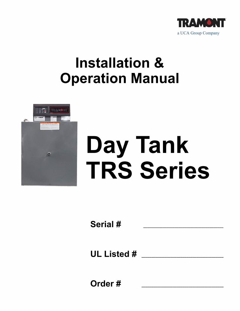
Serial # _________________________________________
UL Listed # __________________________________________
Order # __________________________________________
a UCA Group Company
Installation & Operation Manual
Day Tank TRS Series
Tramont Manufacturing TRS Series Day Tank
Installation and Operation
Table of Contents
Warnings .................................................................................................................. 1
TRS Series Day Tanks ............................................................................................ 2
System 2000PLUS™ ECM ...................................................................................... 3
Installation Diagram: Main Tank Above Day Tank .................................................. 4
Installation Diagram: Main Tank Below Day Tank ................................................... 5
Installation Diagram: Main Tank Below Day Tank, Piping Above Day Tank ........... 6
TRS Series Start-up and Test Procedures .............................................................. 7
Tramont Standard Day Tank Diagrams ................................................................. 12
Tramont Day Tank Specifications .......................................................................... 13
System 2000PLUS ECM Specifications ................................................................ 14
Standard Pump and Motor Specifications ............................................................. 17
Design Considerations of a Day Tank Fuel Transfer system ................................ 18
Mechanical and Plumbing Guide ........................................................................... 21
Sequence of Operation - TRS Day Tank ............................................................... 23
Trouble-shooting Tips: ECM Functional Light Flashing ........................................ 24
System 2000PLUS Problem Report ...................................................................... 25
Common Day Tank Parts....................................................................................... 26
Tramont Manufacturing LLC Product Warranty ..................................................... 27
Tramont Manufacturing LLC 3701 N. Humboldt Blvd.
Milwaukee, Wisconsin, USA 53212 Phone: 414-967-8800 Fax: 414-967-8811 [email protected] www.tramont.com
TRS Series Day Tank
Tramont Manufacturing 3701 N. Humboldt Blvd. Milwaukee, WI 53212
Phone: 414-967-8800 Fax: 414-967-8811 [email protected] www.tramont.com © Tramont Manufacturing June 2017
1.
WARNINGS This Day Tank has been pressure tested to 5 psi for weld integrity. However, IT IS NOT DESIGNED
TO BE A PRESSURE VESSEL.
This tank is designed, manufactured and intended for DIESEL FUEL ONLY.
This tank is intended for STATIONARY INSTALLATIONS ONLY.
Installation of solenoid valves, check valves, or other devices may be required to ensure tank does
not overflow due to fuel draining from pipes that are situated higher than the Day Tank.
The overflow fitting of this atmospheric Day Tank must be plumbed without downsizing in a
CONTINUOUS DOWNWARD PATH to the main tank. If you are unable to plumb in a continuous
downward path, A REVERSE PUMP IS REQUIRED. Consult factory for more information.
If a continuous downward path is impossible, consult the installation guide or factory for overflow
safety requirements. (Installation for Main Tank Above Day Tank).
OPTIONAL EPOXY LINING
To prevent fuel contamination and deterioration of the epoxy lining, this tank must be allowed
to properly cure. The curing time is seven (7) days from the time of application.
This tank lining was applied on ____________________________________
TRS Series Day Tank
Tramont Manufacturing 3701 N. Humboldt Blvd. Milwaukee, WI 53212
Phone: 414-967-8800 Fax: 414-967-8811 [email protected] www.tramont.com © Tramont Manufacturing June 2017
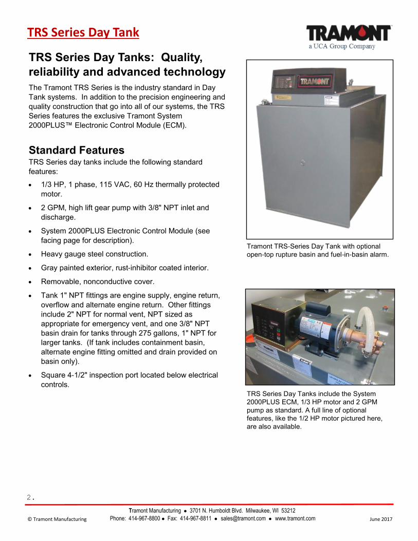
TRS Series Day Tanks: Quality,
reliability and advanced technology
The Tramont TRS Series is the industry standard in Day
Tank systems. In addition to the precision engineering and
quality construction that go into all of our systems, the TRS
Series features the exclusive Tramont System
2000PLUS™ Electronic Control Module (ECM).
Standard Features TRS Series day tanks include the following standard
features:
• 1/3 HP, 1 phase, 115 VAC, 60 Hz thermally protected
motor.
• 2 GPM, high lift gear pump with 3/8" NPT inlet and
discharge.
• System 2000PLUS Electronic Control Module (see
facing page for description).
• Heavy gauge steel construction.
• Gray painted exterior, rust-inhibitor coated interior.
• Removable, nonconductive cover.
• Tank 1" NPT fittings are engine supply, engine return,
overflow and alternate engine return. Other fittings
include 2" NPT for normal vent, NPT sized as
appropriate for emergency vent, and one 3/8" NPT
basin drain for tanks through 275 gallons, 1" NPT for
larger tanks. (If tank includes containment basin,
alternate engine fitting omitted and drain provided on
basin only).
• Square 4-1/2" inspection port located below electrical
controls.
TRS Series Day Tanks include the System
2000PLUS ECM, 1/3 HP motor and 2 GPM
pump as standard. A full line of optional
features, like the 1/2 HP motor pictured here,
are also available.
Tramont TRS-Series Day Tank with optional
open-top rupture basin and fuel-in-basin alarm.
2.

© Tramont Manufacturing June 2017
Tramont Manufacturing 3701 N. Humboldt Blvd. Milwaukee, WI 53212
Phone: 414-967-8800 Fax: 414-967-8811 [email protected] www.tramont.com
TRS Series Day Tank
The System 2000PLUS ECM:
The leading performer in Day
Tank monitoring and control
The System 2000PLUS™ Electronic Control Module
(ECM) gives you state-of-the-art control of your Day
Tank system. The System 2000PLUS is standardly
included on all Tramont TRS Series day tanks. This UL
Listed, microprocessor-based ECM represents a
significant advance in fuel system control. Old-style
controllers utilize individual, electro-mechanical float
switches for each monitoring function. A malfunction
can go undetected for months or years until there is a
crisis. The System 2000PLUS is self-diagnostic, and
features a single sensor for main monitoring functions.
It lets you know immediately if there is a problem. You
have time to react, avoiding a costly disruption. The
System 2000PLUS gives you fast, accurate,
comprehensive monitoring, and is available exclusively
from Tramont.
Standard Features
The System 2000PLUS ECM offers the following
standard features:
• UL 508 Listed.
• Operates on standard 120 VAC, 1 phase system,
50/60 Hz.
• LED indicators for all functions.
• Fuel level sensor.
• Motor control relay with LED signal, rated up to 1/2
HP.
• High and low fuel level warnings.
• Critical low fuel level warning for engine shutoff.
• Fuel-in-rupture-basin warning interface.
• ECM functional signal.
• Manual control with On, Off and Test buttons.
• Secure internal test button for testing warning LEDs
and remote annunciation of warnings.
3.
Tramont Manufacturing LLC
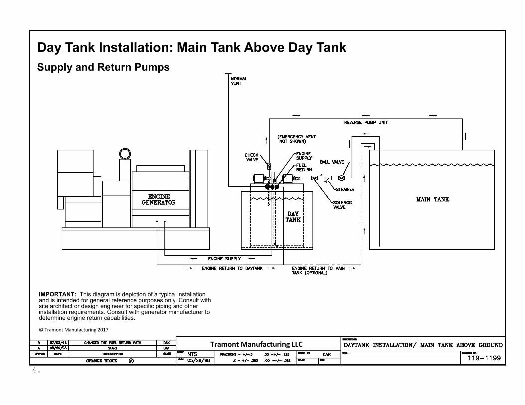
IMPORTANT: This diagram is depiction of a typical installation and is intended for general reference purposes only. Consult with site architect or design engineer for specific piping and other installation requirements. Consult with generator manufacturer to determine engine return capabilities. © Tramont Manufacturing 2017
Day Tank Installation: Main Tank Above Day Tank
Supply and Return Pumps
4.
Tramont Manufacturing LLC
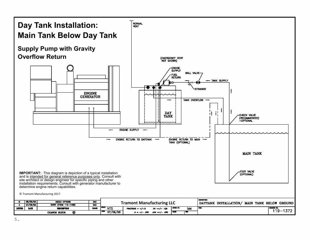
Day Tank Installation:
Main Tank Below Day Tank
Supply Pump with Gravity
Overflow Return
5.
IMPORTANT: This diagram is depiction of a typical installation and is intended for general reference purposes only. Consult with site architect or design engineer for specific piping and other installation requirements. Consult with generator manufacturer to determine engine return capabilities. © Tramont Manufacturing 2017
Tramont Manufacturing LLC
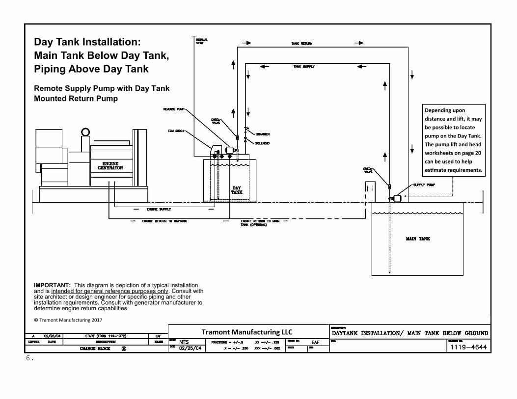
Day Tank Installation:
Main Tank Below Day Tank,
Piping Above Day Tank
Remote Supply Pump with Day Tank
Mounted Return Pump
6.
Depending upon
distance and lift, it may
be possible to locate
pump on the Day Tank.
The pump lift and head
worksheets on page 20
can be used to help
estimate requirements.
IMPORTANT: This diagram is depiction of a typical installation and is intended for general reference purposes only. Consult with site architect or design engineer for specific piping and other installation requirements. Consult with generator manufacturer to determine engine return capabilities. © Tramont Manufacturing 2017
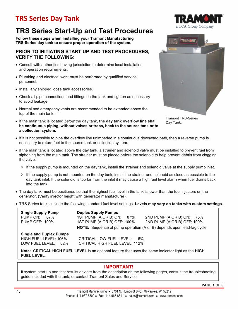
TRS Series Start-Up and Test Procedures
Follow these steps when installing your Tramont Manufacturing TRS-Series day tank to ensure proper operation of the system.
PRIOR TO INITIATING START-UP AND TEST PROCEDURES,
VERIFY THE FOLLOWING:
• Consult with authorities having jurisdiction to determine local installation
and operation requirements.
• Plumbing and electrical work must be performed by qualified service
personnel.
• Install any shipped loose tank accessories.
• Check all pipe connections and fittings on the tank and tighten as necessary
to avoid leakage.
• Normal and emergency vents are recommended to be extended above the
top of the main tank.
• If the main tank is located below the day tank, the day tank overflow line shall
be continuous piping, without valves or traps, back to the source tank or to
a collection system.
• If it is not possible to pipe the overflow line unimpeded in a continuous downward path, then a reverse pump is
necessary to return fuel to the source tank or collection system.
• If the main tank is located above the day tank, a strainer and solenoid valve must be installed to prevent fuel from
siphoning from the main tank. The strainer must be placed before the solenoid to help prevent debris from clogging
the valve:
If the supply pump is mounted on the day tank, install the strainer and solenoid valve at the supply pump inlet.
If the supply pump is not mounted on the day tank, install the strainer and solenoid as close as possible to the
day tank inlet. If the solenoid is too far from the inlet it may cause a high fuel level alarm when fuel drains back
into the tank.
• The day tank must be positioned so that the highest fuel level in the tank is lower than the fuel injectors on the
generator. (Verify injector height with generator manufacturer).
• TRS Series tanks include the following standard fuel level settings. Levels may vary on tanks with custom settings.
Single Supply Pump Duplex Supply Pumps
PUMP ON: 87% 1ST PUMP (A OR B) ON: 87% 2ND PUMP (A OR B) ON: 75%
PUMP OFF: 100% 1ST PUMP (A OR B) OFF: 100% 2ND PUMP (A OR B) OFF: 100%
NOTE: Sequence of pump operation (A or B) depends upon lead-lag cycle.
Single and Duplex Pumps
HIGH FUEL LEVEL: 106% CRITICAL LOW FUEL LEVEL: 6%
LOW FUEL LEVEL: 62% CRITICAL HIGH FUEL LEVEL: 112%
Note: CRITICAL HIGH FUEL LEVEL is an optional feature that uses the same indicator light as the HIGH
FUEL LEVEL.
IMPORTANT! If system start-up and test results deviate from the description on the following pages, consult the troubleshooting
guide included with the tank, or contact Tramont Sales and Service.
TRS Series Day Tank
Tramont Manufacturing 3701 N. Humboldt Blvd. Milwaukee, WI 53212
Phone: 414-967-8800 Fax: 414-967-8811 [email protected] www.tramont.com 7.
PAGE 1 OF 5
Tramont TRS-Series
Day Tank.
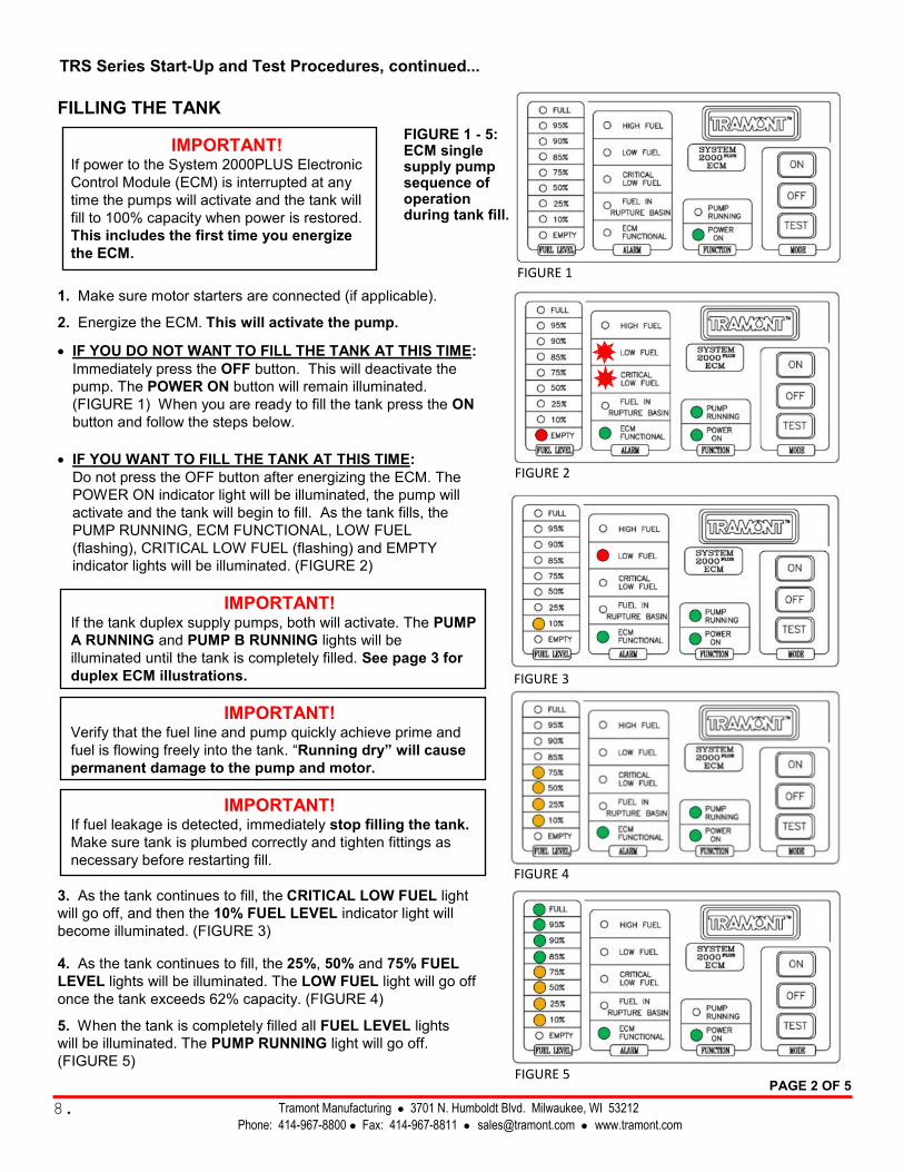
FILLING THE TANK
IMPORTANT! If power to the System 2000PLUS Electronic
Control Module (ECM) is interrupted at any
time the pumps will activate and the tank will
fill to 100% capacity when power is restored.
This includes the first time you energize
the ECM.
1. Make sure motor starters are connected (if applicable).
2. Energize the ECM. This will activate the pump.
• IF YOU DO NOT WANT TO FILL THE TANK AT THIS TIME:
Immediately press the OFF button. This will deactivate the
pump. The POWER ON button will remain illuminated.
(FIGURE 1) When you are ready to fill the tank press the ON
button and follow the steps below.
• IF YOU WANT TO FILL THE TANK AT THIS TIME:
Do not press the OFF button after energizing the ECM. The
POWER ON indicator light will be illuminated, the pump will
activate and the tank will begin to fill. As the tank fills, the
PUMP RUNNING, ECM FUNCTIONAL, LOW FUEL
(flashing), CRITICAL LOW FUEL (flashing) and EMPTY
indicator lights will be illuminated. (FIGURE 2)
IMPORTANT! If the tank duplex supply pumps, both will activate. The PUMP
A RUNNING and PUMP B RUNNING lights will be
illuminated until the tank is completely filled. See page 3 for
duplex ECM illustrations.
IMPORTANT! Verify that the fuel line and pump quickly achieve prime and
fuel is flowing freely into the tank. “Running dry” will cause
permanent damage to the pump and motor.
IMPORTANT! If fuel leakage is detected, immediately stop filling the tank.
Make sure tank is plumbed correctly and tighten fittings as
necessary before restarting fill.
3. As the tank continues to fill, the CRITICAL LOW FUEL light
will go off, and then the 10% FUEL LEVEL indicator light will
become illuminated. (FIGURE 3)
4. As the tank continues to fill, the 25%, 50% and 75% FUEL
LEVEL lights will be illuminated. The LOW FUEL light will go off
once the tank exceeds 62% capacity. (FIGURE 4)
5. When the tank is completely filled all FUEL LEVEL lights
will be illuminated. The PUMP RUNNING light will go off.
(FIGURE 5)
Tramont Manufacturing 3701 N. Humboldt Blvd. Milwaukee, WI 53212
Phone: 414-967-8800 Fax: 414-967-8811 [email protected] www.tramont.com
TRS Series Start-Up and Test Procedures, continued...
FIGURE 1 - 5: ECM single supply pump sequence of operation during tank fill.
FIGURE 1
FIGURE 3
FIGURE 2
FIGURE 4
FIGURE 5 PAGE 2 OF 5
8.
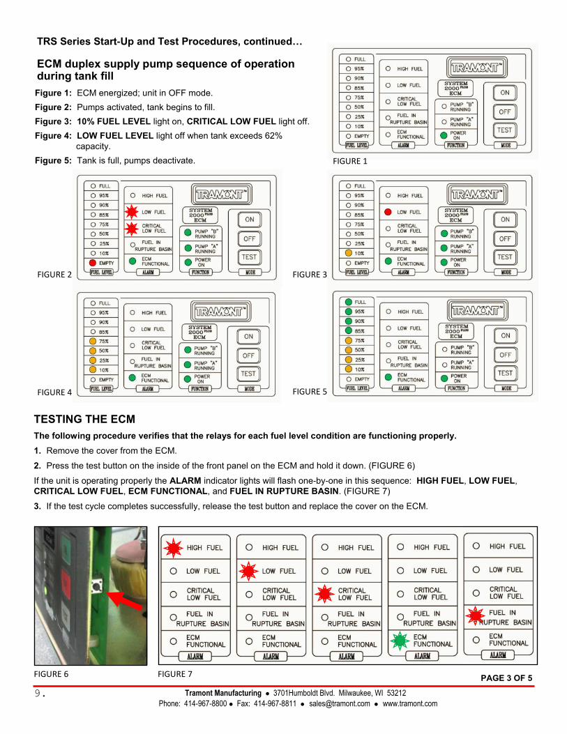
TESTING THE ECM
The following procedure verifies that the relays for each fuel level condition are functioning properly.
1. Remove the cover from the ECM.
2. Press the test button on the inside of the front panel on the ECM and hold it down. (FIGURE 6)
If the unit is operating properly the ALARM indicator lights will flash one-by-one in this sequence: HIGH FUEL, LOW FUEL,
CRITICAL LOW FUEL, ECM FUNCTIONAL, and FUEL IN RUPTURE BASIN. (FIGURE 7)
3. If the test cycle completes successfully, release the test button and replace the cover on the ECM.
FIGURE 6
FIGURE 2 FIGURE 3
FIGURE 4 FIGURE 5
FIGURE 1
FIGURE 7
Tramont Manufacturing 3701Humboldt Blvd. Milwaukee, WI 53212
Phone: 414-967-8800 Fax: 414-967-8811 [email protected] www.tramont.com
Figure 1: ECM energized; unit in OFF mode.
Figure 2: Pumps activated, tank begins to fill.
Figure 3: 10% FUEL LEVEL light on, CRITICAL LOW FUEL light off.
Figure 4: LOW FUEL LEVEL light off when tank exceeds 62%
capacity.
Figure 5: Tank is full, pumps deactivate.
TRS Series Start-Up and Test Procedures, continued…
ECM duplex supply pump sequence of operation during tank fill
PAGE 3 OF 5
9.
TRS Series Start-Up and Test Procedures, continued...
TESTING THE OVERFILL LINE
For tanks with a gravity fed return line The purpose of this test is to verify that the overfill line is plumbed in
a continuous downward path with no obstructions so that excess fuel
flows unimpeded back to the main tank.
IMPORTANT! Carefully monitor the fuel level while performing these steps. If the
overfill line is not plumbed correctly and fuel continues to enter the
day tank a fuel spill may occur.
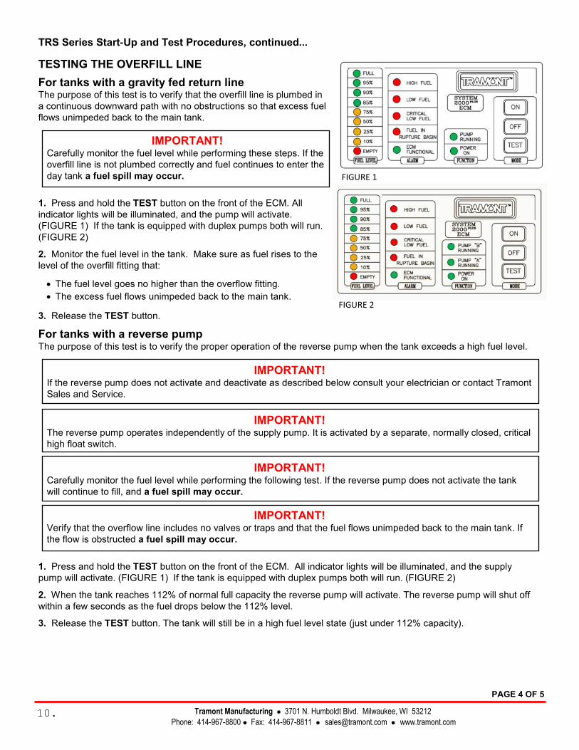
1. Press and hold the TEST button on the front of the ECM. All
indicator lights will be illuminated, and the pump will activate.
(FIGURE 1) If the tank is equipped with duplex pumps both will run.
(FIGURE 2)
2. Monitor the fuel level in the tank. Make sure as fuel rises to the
level of the overfill fitting that:
• The fuel level goes no higher than the overflow fitting.
• The excess fuel flows unimpeded back to the main tank.
3. Release the TEST button.
For tanks with a reverse pump The purpose of this test is to verify the proper operation of the reverse pump when the tank exceeds a high fuel level.
IMPORTANT! If the reverse pump does not activate and deactivate as described below consult your electrician or contact Tramont
Sales and Service.
IMPORTANT! The reverse pump operates independently of the supply pump. It is activated by a separate, normally closed, critical
high float switch.
IMPORTANT! Carefully monitor the fuel level while performing the following test. If the reverse pump does not activate the tank
will continue to fill, and a fuel spill may occur.
IMPORTANT! Verify that the overflow line includes no valves or traps and that the fuel flows unimpeded back to the main tank. If
the flow is obstructed a fuel spill may occur.
1. Press and hold the TEST button on the front of the ECM. All indicator lights will be illuminated, and the supply
pump will activate. (FIGURE 1) If the tank is equipped with duplex pumps both will run. (FIGURE 2)
2. When the tank reaches 112% of normal full capacity the reverse pump will activate. The reverse pump will shut off
within a few seconds as the fuel drops below the 112% level.
3. Release the TEST button. The tank will still be in a high fuel level state (just under 112% capacity).
FIGURE 1
FIGURE 2
PAGE 4 OF 5
Tramont Manufacturing 3701 N. Humboldt Blvd. Milwaukee, WI 53212
Phone: 414-967-8800 Fax: 414-967-8811 [email protected] www.tramont.com 10.
TRS Series Start-Up and Test Procedures, continued...
TESTING THE FUEL-IN-BASIN SWITCH
The fuel-in-basin switch, also referred to as a “leak detection switch,” is designed
to detect the presence of fuel in the containment basin. The switch is installed and
connected to the ECM. Follow the steps below if you would like to test the switch
to verify it has not been damaged in shipping and is working properly.
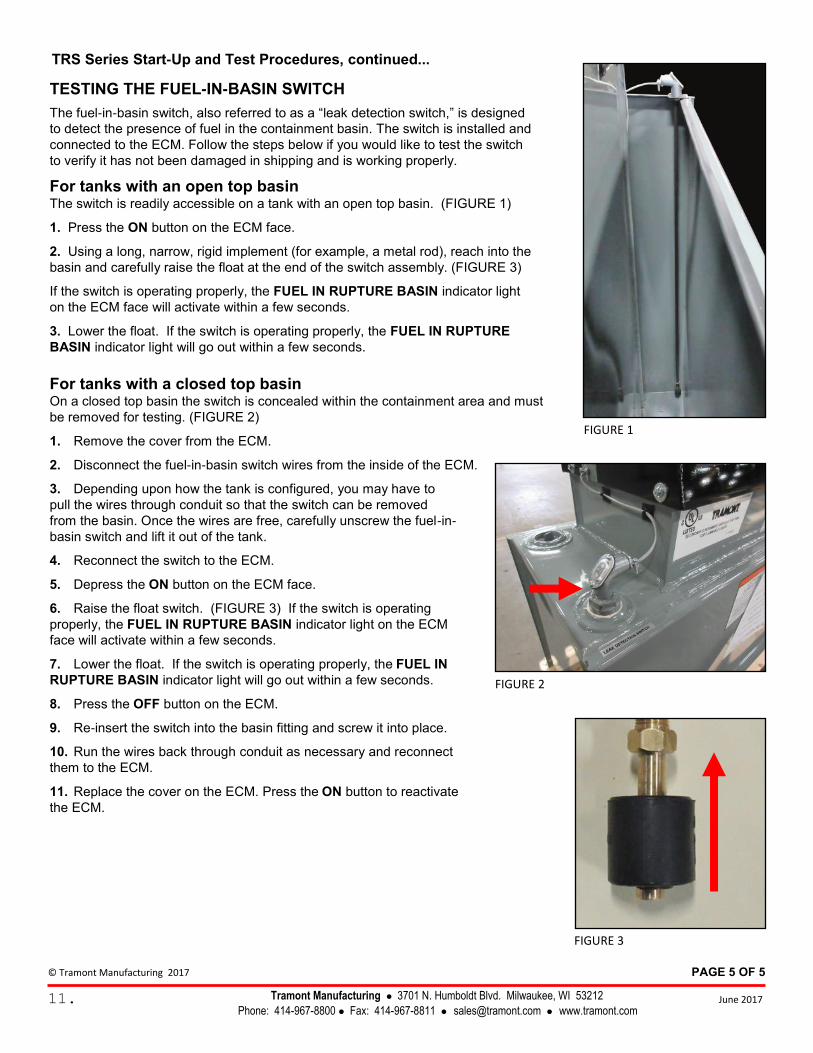
For tanks with an open top basin The switch is readily accessible on a tank with an open top basin. (FIGURE 1)
1. Press the ON button on the ECM face.
2. Using a long, narrow, rigid implement (for example, a metal rod), reach into the
basin and carefully raise the float at the end of the switch assembly. (FIGURE 3)
If the switch is operating properly, the FUEL IN RUPTURE BASIN indicator light
on the ECM face will activate within a few seconds.
3. Lower the float. If the switch is operating properly, the FUEL IN RUPTURE
BASIN indicator light will go out within a few seconds.
For tanks with a closed top basin On a closed top basin the switch is concealed within the containment area and must
be removed for testing. (FIGURE 2)
1. Remove the cover from the ECM.
2. Disconnect the fuel-in-basin switch wires from the inside of the ECM.
3. Depending upon how the tank is configured, you may have to
pull the wires through conduit so that the switch can be removed
from the basin. Once the wires are free, carefully unscrew the fuel-in-
basin switch and lift it out of the tank.
4. Reconnect the switch to the ECM.
5. Depress the ON button on the ECM face.
6. Raise the float switch. (FIGURE 3) If the switch is operating
properly, the FUEL IN RUPTURE BASIN indicator light on the ECM
face will activate within a few seconds.
7. Lower the float. If the switch is operating properly, the FUEL IN
RUPTURE BASIN indicator light will go out within a few seconds.
8. Press the OFF button on the ECM.
9. Re-insert the switch into the basin fitting and screw it into place.
10. Run the wires back through conduit as necessary and reconnect
them to the ECM.
11. Replace the cover on the ECM. Press the ON button to reactivate
the ECM.
PAGE 5 OF 5
June 2017 Tramont Manufacturing 3701 N. Humboldt Blvd. Milwaukee, WI 53212
Phone: 414-967-8800 Fax: 414-967-8811 [email protected] www.tramont.com
FIGURE 1
FIGURE 2
FIGURE 3
11.
© Tramont Manufacturing 2017

Day Tank
Tramont Manufacturing 3701 N. Humboldt Blvd. Milwaukee, WI 53212
Phone: 414-967-8800 Fax: 414-967-8811 [email protected] www.tramont.com © Tramont Manufacturing June 2017
12.
Drain is 1” NPT on tanks 300 gallons and above.
On tanks with basin:
• Drain is on basin only
• Alternate engine fitting is eliminated
• Engine supply fitting is moved to top of tank
with 2” vent, overflow and fuel return fitting.
Tramont Standard Day Tank Diagrams
IMPORTANT: These diagrams depict standard Tramont Manufacturing Day Tanks.
The appearance and configuration of a Day Tank may vary due to special customer requests.
2” NPT VENT
Day Tank
Tramont Manufacturing 3701 N. Humboldt Blvd. Milwaukee, WI 53212
Phone: 414-967-8800 Fax: 414-967-8811 [email protected] www.tramont.com © Tramont Manufacturing June 2017
13.
Tramont Day Tank System Specifications
TRS Series Day Tank
Tramont Manufacturing 3701 N. Humboldt Blvd. Milwaukee, WI 53212
Phone: 414-967-8800 Fax: 414-967-8811 [email protected] www.tramont.com © Tramont Manufacturing June 2017
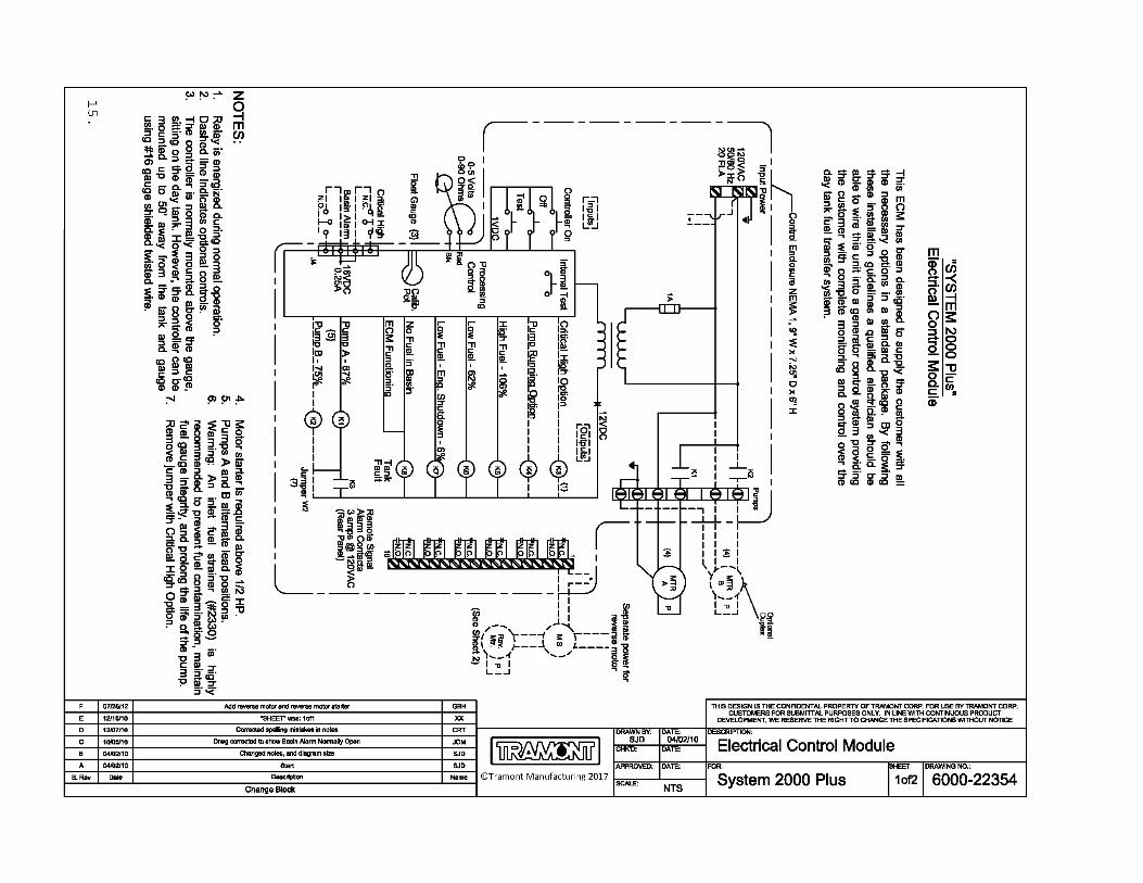
Day Tank Control Specification: System 2000PLUS™ ECM GENERAL This section covers the electrical description and installation of the Tramont standard System 2000PLUS™ electronic control module (ECM). Installation of the ECM should be performed by a qualified electrician. These specifications provide information on standard System 2000PLUS features.
DESCRIPTION The heart of the “SYSTEM 2000” ECM is an electrical analog float gauge providing signals to the ECM for:
Fuel level indication Pump control High fuel level warning Low fuel level warning Low fuel level shut off ECM functional signal All signals and warnings are provided with N.O. and N.C. contacts for remote annunciation. The ECM can be manually controlled by ON, OFF, and TEST push buttons. In addition, an internal test button allows for a periodic test of all warning LEDs and remote annunciation relays.
FUNCTIONS The purpose of the ECM is to maintain the fuel level of the Day Tank by controlling a pump/motor. The pump is off at the normal fuel level and is activated at 87% full. A “pump running” indicator LED is on when the pump is activated. Motor relay is prewired to pump motor.
WARNING: When ECM “OFF” push button is engaged the unit is disabled, however, 120 VAC power is still present within the ECM, indicated by the “power on” LED.
OPTIONS 1920 Duplex pumping system. Adds 2nd pump and motor for safety redundancy. Control alternates lead pump.
1930 Controls are available for 12 VDC operation. Single or duplex. Consult factory for specifications.
3240 Pump running contacts for remote annunciation.
3250 Critical high shutdown. Separate float switch senses critical high fuel level, disengaging motor and optional solenoid valve. Warning relay supplied for remote annunciation.
INCOMING POWER The ECM is powered by a customer-supplied 120 VAC line. Power terminals are accessible by removing four cover screws on the ECM and removing the ECM cover exposing the terminal strip. Wires should be run through knockout provided.
LEVEL SENSOR The day tank’s level is determined by an electrical analog float sender located below the ECM on the inspection plate cover. The sensor provides a 0 – 90-ohm signal to the ECM, which converts it to a precise fuel level. Fuel level is indicated by nine incremental LEDs on the ECM from EMPTY to FULL.
ALARMS The ECM has five standard alarm conditions. Each alarm is indicated locally by an LED and remotely by wiring to supplied relays. A normally open and normally closed contact is provided for customer connections. Contacts are rated at 3 amps, 120 VAC or 24 VDC.
High fuel: Activates at 106% of normal fuel level with a two second change of state time delay.
Low fuel: Activates at 62% of normal fuel level. This enables user time to react to a potential problem before low fuel shutdown occurs.
Low fuel shutdown: Activates at 6% of normal fuel level. This enables user to shut down engine generator before fuel runs out, preventing loss of prime or engine damage.
Fuel in rupture basin: With a rupture basin float switch, (option #2930) the ECM will signal if fuel is in the rupture basin.
ECM functional: The ECM performs many internal checks (including float gauge) to ensure proper operation. If a fault occurs, this LED will go from constant to flashing and de-energize the relay. It is suggested that the customer wire to the normally closed contact thereby providing a signal if a fault does occur.
MODE There are four modes of operation on the ECM:
Off: This pushbutton disables the ECM for routine maintenance to the tank system.
Caution: ECM functional de-energizes, which can activate a customer alarm wired to this relay.
On: This pushbutton activates the ECM after the Off pushbutton has been depressed. On any initial power-up condition, after a power outage, the ECM will automatically turn on.
Test: This pushbutton will test all front panel LEDs and activate pump/motor for as long as the button is depressed. All alarm relays will not activate, but will maintain their original state.
Internal test: This pushbutton, located inside the ECM, will test each LED and remote annunciation relay in sequential order for three seconds, high fuel to ECM functional.
NOTE: It is recommended that both the external and internal test switch be activated as part of a periodic maintenance program to ensure reliable operation of the Day Tank.
14.
Day Tank
17.
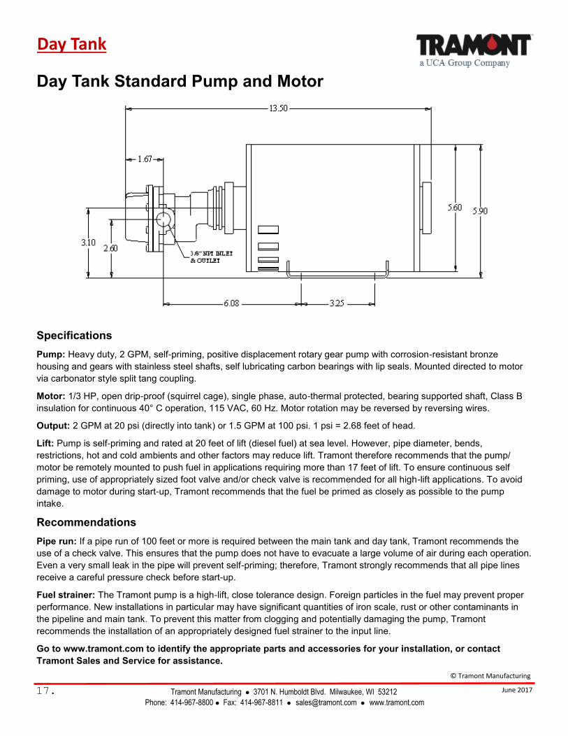
Day Tank Standard Pump and Motor
Specifications
Pump: Heavy duty, 2 GPM, self-priming, positive displacement rotary gear pump with corrosion-resistant bronze
housing and gears with stainless steel shafts, self lubricating carbon bearings with lip seals. Mounted directed to motor
via carbonator style split tang coupling.
Motor: 1/3 HP, open drip-proof (squirrel cage), single phase, auto-thermal protected, bearing supported shaft, Class B
insulation for continuous 40° C operation, 115 VAC, 60 Hz. Motor rotation may be reversed by reversing wires.
Output: 2 GPM at 20 psi (directly into tank) or 1.5 GPM at 100 psi. 1 psi = 2.68 feet of head.
Lift: Pump is self-priming and rated at 20 feet of lift (diesel fuel) at sea level. However, pipe diameter, bends,
restrictions, hot and cold ambients and other factors may reduce lift. Tramont therefore recommends that the pump/
motor be remotely mounted to push fuel in applications requiring more than 17 feet of lift. To ensure continuous self
priming, use of appropriately sized foot valve and/or check valve is recommended for all high-lift applications. To avoid
damage to motor during start-up, Tramont recommends that the fuel be primed as closely as possible to the pump
intake.
Recommendations
Pipe run: If a pipe run of 100 feet or more is required between the main tank and day tank, Tramont recommends the
use of a check valve. This ensures that the pump does not have to evacuate a large volume of air during each operation.
Even a very small leak in the pipe will prevent self-priming; therefore, Tramont strongly recommends that all pipe lines
receive a careful pressure check before start-up.
Fuel strainer: The Tramont pump is a high-lift, close tolerance design. Foreign particles in the fuel may prevent proper
performance. New installations in particular may have significant quantities of iron scale, rust or other contaminants in
the pipeline and main tank. To prevent this matter from clogging and potentially damaging the pump, Tramont
recommends the installation of an appropriately designed fuel strainer to the input line.
Go to www.tramont.com to identify the appropriate parts and accessories for your installation, or contact
Tramont Sales and Service for assistance.
© Tramont Manufacturing
June 2017 Tramont Manufacturing 3701 N. Humboldt Blvd. Milwaukee, WI 53212
Phone: 414-967-8800 Fax: 414-967-8811 [email protected] www.tramont.com
DAY TANKS
Design Considerations of a Day Tank Fuel Transfer System
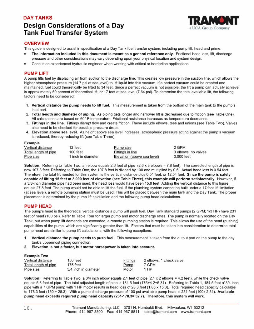
OVERVIEW This guide is designed to assist in specification of a Day Tank fuel transfer system, including pump lift, head and prime.
• The information included in this document is meant as a general reference only. Frictional head loss, lift, discharge
pressure and other considerations may vary depending upon your physical location and system design.
• Consult an experienced hydraulic engineer when working with critical or borderline applications.
PUMP LIFT A pump lifts fuel by displacing air from suction to the discharge line. This creates low pressure in the suction line, which allows the
higher atmospheric pressure (14.7 psi at sea level) to lift liquid into this vacuum. If a perfect vacuum could be created and
maintained, fuel could theoretically be lifted to 34 feet. Since a perfect vacuum is not possible, the lift a pump can actually achieve
is approximately 50 percent of theoretical lift, or 17 feet at sea level (7.64 psi). To determine the total available lift, the following
factors need to be considered:
1. Vertical distance the pump needs to lift fuel. This measurement is taken from the bottom of the main tank to the pump’s
inlet port.
2. Total length and diameter of piping. As piping gets longer and narrower lift is decreased due to friction (see Table One).
All calculations are based on 60° F temperature. Frictional resistance increases as temperature decreases.
3. Fittings in the line. Fittings disrupt flow and create friction. These include elbows, tees and unions (see Table Two). Valves
also need to be checked for possible pressure drops.
4. Elevation above sea level. As height above sea level increases, atmospheric pressure acting against the pump’s vacuum
is reduced, thereby reducing lift (see Table Three).
Example
Vertical distance 12 feet Pump size 2 GPM
Total length of pipe 100 feet Fittings in line 3 elbows, no valves
Pipe size 1 inch in diameter Elevation (above sea level) 3,000 feet
Solution: Referring to Table Two, an elbow equals 2.6 feet of pipe (2.6 x 3 elbows = 7.8 feet). The corrected length of pipe is
now 107.8 feet. Referring to Table One, the 107.8 feet is divided by 100 and multiplied by 0.5. Actual head loss is 0.54 feet.
Therefore, the total lift needed for this system is the vertical distance plus 0.54 feet, or 12.54 feet. Since the pump is safely
capable of lifting 15 feet at 3,000 feet of elevation (see Table Three), this example will perform satisfactorily. However, if
a 3/8-inch diameter pipe had been used, the head loss would have been 15.8 feet. Adding the vertical distance to this figure
equals 27.8 feet. The pump would not be able to lift the fuel. If the plumbing system cannot be built under a 17-foot lift limitation
(at sea level), a remote pumping station must be used. This will be placed between the main tank and the Day Tank. The proper
placement is determined by the pump lift calculation and the following pump head calculations.
PUMP HEAD The pump’s head is the theoretical vertical distance a pump will push fuel. Day Tank standard pumps (2 GPM; 1/3 HP) have 231
feet of head (100 psi). Refer to Table Four for larger pump and motor discharge rates. The pump is normally located on the Day
Tank, but when pump lift demands are exceeded, a remote pumping station is required. This allows the use of the head (pushing)
capabilities of the pump, which are significantly greater than lift. Factors that must be taken into consideration to determine total
pump head are similar to pump lift calculations, with the following exceptions:
1. Vertical distance the pump needs to push fuel: This measurement is taken from the output port on the pump to the day
tank’s uppermost piping connection.
2. Elevation is not a factor, but motor horsepower is taken into account.
Example Two
Vertical distance 150 feet Fittings 2 elbows, 1 check valve
Total length of pipe 175 feet Pump 7 GPM
Pipe size 3/4 inch in diameter Motor 1 HP
Solution: Referring to Table Two, a 3/4 inch elbow equals 2.1 feet of pipe (2.1 x 2 elbows = 4.2 feet), while the check valve
equals 5.3 feet of pipe. The total adjusted length of pipe is 184.5 feet (175+4.2+5.31). Referring to Table 1, 184.5 feet of 3/4 inch
pipe with a 7 GPM pump with 1 HP motor results in head loss of 28.3 feet (1.85 x 15.3). Total required head capacity calculates
to 178.3 feet (150 + 28.3). With a pump discharge pressure of 100 psi available pump head is 231 feet (100x 2.31). Available
pump head exceeds required pump head capacity (231-178.3= 52.7). Therefore, this system will work.
_____________________________________________________________________________________________________________________________________________
Tramont Manufacturing, LLC 3701 N. Humboldt Blvd. Milwaukee, WI 53212 Phone: 414-967-8800 Fax: 414-967-8811 [email protected] www.tramont.com
18.
DAY TANKS Design Considerations of a Day Tank Fuel Transfer System, p. 2
PUMP PRIME Maintaining the prime on a pump is critical. Fuel must be maintained in the suction side pipe with no air pockets. Foot valves at
the main tank or check valves at the Day Tank can be used to prevent fuel flowing back to the main tank and losing prime.
Pump cavitation can occur when a pump is unable to properly discharge fuel. There are multiple causes, including:
Total equivalent lift too high for pump Improperly plumbed systems Air leaks
Total equivalent head too high for pump Restrictions in lines
Cavitation can occur gradually and will eventually ruin a pump. Vertical piping loops or “traps” should be avoided when designing
a pumping system. Air pockets can become trapped in the high point of the vertical loop, resulting in pump cavitation. A hand
pump is recommended for initial priming to avoid undue wear on the fuel pump. If the fuel pump must be used for initial priming,
do not run for more than 60 seconds. Fuel should be flowing within that time. A fuel strainer is also recommended on the inlet
side of the pump. Foreign particles entering the pump chamber will diminish its life expectancy. The strainer should be checked
periodically to avoid particle build-up, which limits pumping capabilities.
SUMMARY Proper engineering practices should always be used when calculating pump head and especially pump lift. By following these
guidelines, costly repairs due to improper installations can be avoided.
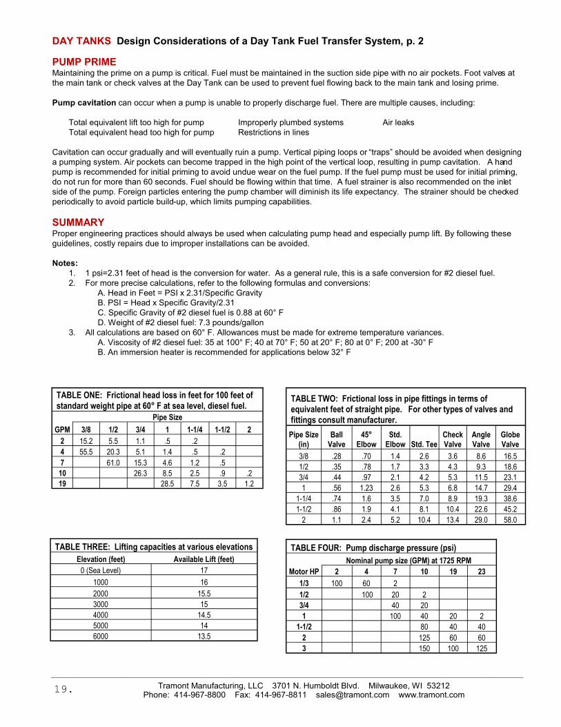
Notes:
1. 1 psi=2.31 feet of head is the conversion for water. As a general rule, this is a safe conversion for #2 diesel fuel.
2. For more precise calculations, refer to the following formulas and conversions:
A. Head in Feet = PSI x 2.31/Specific Gravity
B. PSI = Head x Specific Gravity/2.31
C. Specific Gravity of #2 diesel fuel is 0.88 at 60° F
D. Weight of #2 diesel fuel: 7.3 pounds/gallon
3. All calculations are based on 60° F. Allowances must be made for extreme temperature variances.
A. Viscosity of #2 diesel fuel: 35 at 100° F; 40 at 70° F; 50 at 20° F; 80 at 0° F; 200 at -30° F
B. An immersion heater is recommended for applications below 32° F
TABLE ONE: Frictional head loss in feet for 100 feet of standard weight pipe at 60° F at sea level, diesel fuel.
Pipe Size
GPM 3/8 1/2 3/4 1 1-1/4 1-1/2 2
2 15.2 5.5 1.1 .5 .2
4 55.5 20.3 5.1 1.4 .5 .2
7 61.0 15.3 4.6 1.2 .5
10 26.3 8.5 2.5 .9 .2
19 28.5 7.5 3.5 1.2
TABLE FOUR: Pump discharge pressure (psi)
Nominal pump size (GPM) at 1725 RPM
Motor HP 2 4 7 10 19 23
1/3 100 60 2
1/2 100 20 2
3/4 40 20
1 100 40 20 2
1-1/2 80 40 40
2 125 60 60
3 150 100 125
_____________________________________________________________________________________________________________________________________________
Tramont Manufacturing, LLC 3701 N. Humboldt Blvd. Milwaukee, WI 53212 Phone: 414-967-8800 Fax: 414-967-8811 [email protected] www.tramont.com
TABLE TWO: Frictional loss in pipe fittings in terms of equivalent feet of straight pipe. For other types of valves and fittings consult manufacturer.
Pipe Size
(in)
Ball
Valve
45°
Elbow
Std.
Elbow Std. Tee
Check
Valve
Angle
Valve
Globe
Valve
3/8 .28 .70 1.4 2.6 3.6 8.6 16.5
1/2 .35 .78 1.7 3.3 4.3 9.3 18.6
3/4 .44 .97 2.1 4.2 5.3 11.5 23.1
1 .56 1.23 2.6 5.3 6.8 14.7 29.4
1-1/4 .74 1.6 3.5 7.0 8.9 19.3 38.6
1-1/2 .86 1.9 4.1 8.1 10.4 22.6 45.2
2 1.1 2.4 5.2 10.4 13.4 29.0 58.0
TABLE THREE: Lifting capacities at various elevations
Elevation (feet) Available Lift (feet)
0 (Sea Level) 17
1000 16
2000 15.5
3000 15
4000 14.5
5000 14
6000 13.5
19.
20.
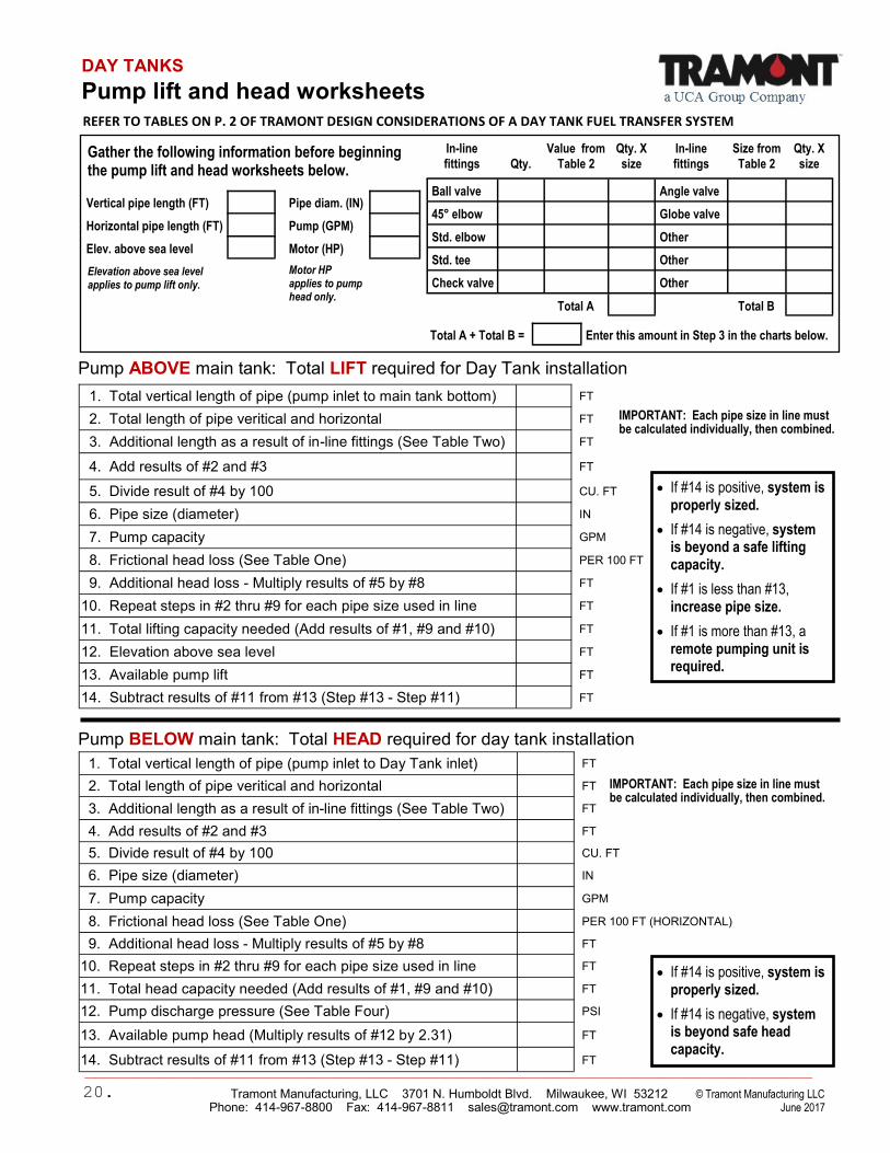
DAY TANKS
Pump lift and head worksheets
Gather the following information before beginning the pump lift and head worksheets below.
• If #14 is positive, system is properly sized.
• If #14 is negative, system is beyond a safe lifting capacity.
• If #1 is less than #13, increase pipe size.
• If #1 is more than #13, a remote pumping unit is required.
Pump BELOW main tank: Total HEAD required for day tank installation
Pump ABOVE main tank: Total LIFT required for Day Tank installation
REFER TO TABLES ON P. 2 OF TRAMONT DESIGN CONSIDERATIONS OF A DAY TANK FUEL TRANSFER SYSTEM
1. Total vertical length of pipe (pump inlet to main tank bottom) FT
2. Total length of pipe veritical and horizontal FT
3. Additional length as a result of in-line fittings (See Table Two) FT
4. Add results of #2 and #3 FT
5. Divide result of #4 by 100 CU. FT
6. Pipe size (diameter) IN
7. Pump capacity GPM
8. Frictional head loss (See Table One) PER 100 FT
9. Additional head loss - Multiply results of #5 by #8 FT
10. Repeat steps in #2 thru #9 for each pipe size used in line FT
11. Total lifting capacity needed (Add results of #1, #9 and #10) FT
12. Elevation above sea level FT
13. Available pump lift FT
14. Subtract results of #11 from #13 (Step #13 - Step #11) FT
IMPORTANT: Each pipe size in line must be calculated individually, then combined.
1. Total vertical length of pipe (pump inlet to Day Tank inlet) FT
2. Total length of pipe veritical and horizontal FT
3. Additional length as a result of in-line fittings (See Table Two) FT
4. Add results of #2 and #3 FT
5. Divide result of #4 by 100 CU. FT
6. Pipe size (diameter) IN
7. Pump capacity GPM
8. Frictional head loss (See Table One) PER 100 FT (HORIZONTAL)
9. Additional head loss - Multiply results of #5 by #8 FT
10. Repeat steps in #2 thru #9 for each pipe size used in line FT
11. Total head capacity needed (Add results of #1, #9 and #10) FT
12. Pump discharge pressure (See Table Four) PSI
13. Available pump head (Multiply results of #12 by 2.31) FT
14. Subtract results of #11 from #13 (Step #13 - Step #11) FT
• If #14 is positive, system is properly sized.
• If #14 is negative, system is beyond safe head capacity.
_________________________________________________________________________________________________________________________________________
Tramont Manufacturing, LLC 3701 N. Humboldt Blvd. Milwaukee, WI 53212 © Tramont Manufacturing LLC Phone: 414-967-8800 Fax: 414-967-8811 [email protected] www.tramont.com June 2017
IMPORTANT: Each pipe size in line must be calculated individually, then combined.
Total A + Total B = Enter this amount in Step 3 in the charts below.
Motor HP applies to pump head only.
Vertical pipe length (FT) Pipe diam. (IN)
Horizontal pipe length (FT) Pump (GPM)
Elev. above sea level Motor (HP)
Elevation above sea level applies to pump lift only.
In-line
fittings
Qty.
Value from
Table 2
Qty. X
size
In-line
fittings
Size from
Table 2
Qty. X
size
Ball valve Angle valve
45° elbow Globe valve
Std. elbow Other
Std. tee Other
Check valve Other
Total A Total B
Day Tank
Tramont Manufacturing 3701 N. Humboldt Blvd. Milwaukee, WI 53212
Phone: 414-967-8800 Fax: 414-967-8811 [email protected] www.tramont.com
21.
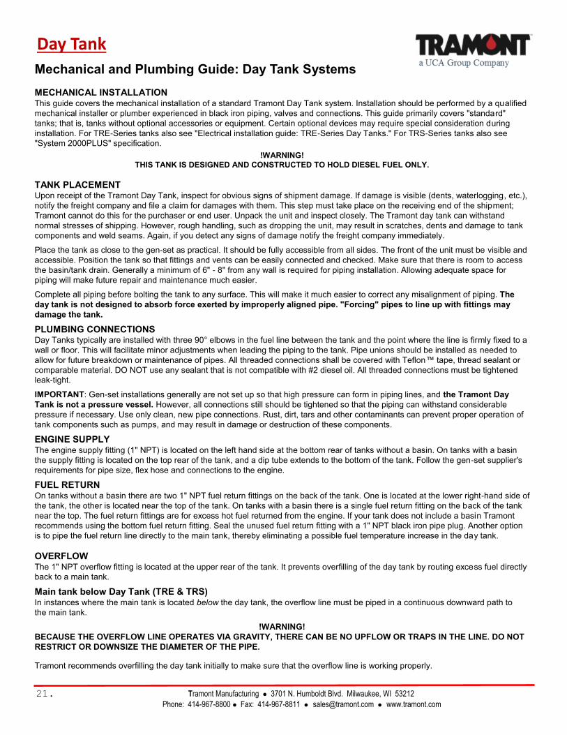
Mechanical and Plumbing Guide: Day Tank Systems
MECHANICAL INSTALLATION This guide covers the mechanical installation of a standard Tramont Day Tank system. Installation should be performed by a qualified
mechanical installer or plumber experienced in black iron piping, valves and connections. This guide primarily covers "standard"
tanks; that is, tanks without optional accessories or equipment. Certain optional devices may require special consideration during
installation. For TRE-Series tanks also see "Electrical installation guide: TRE-Series Day Tanks." For TRS-Series tanks also see
"System 2000PLUS" specification.
!WARNING!
THIS TANK IS DESIGNED AND CONSTRUCTED TO HOLD DIESEL FUEL ONLY.
TANK PLACEMENT Upon receipt of the Tramont Day Tank, inspect for obvious signs of shipment damage. If damage is visible (dents, waterlogging, etc.),
notify the freight company and file a claim for damages with them. This step must take place on the receiving end of the shipment;
Tramont cannot do this for the purchaser or end user. Unpack the unit and inspect closely. The Tramont day tank can withstand
normal stresses of shipping. However, rough handling, such as dropping the unit, may result in scratches, dents and damage to tank
components and weld seams. Again, if you detect any signs of damage notify the freight company immediately.
Place the tank as close to the gen-set as practical. It should be fully accessible from all sides. The front of the unit must be visible and
accessible. Position the tank so that fittings and vents can be easily connected and checked. Make sure that there is room to access
the basin/tank drain. Generally a minimum of 6" - 8" from any wall is required for piping installation. Allowing adequate space for
piping will make future repair and maintenance much easier.
Complete all piping before bolting the tank to any surface. This will make it much easier to correct any misalignment of piping. The
day tank is not designed to absorb force exerted by improperly aligned pipe. "Forcing" pipes to line up with fittings may
damage the tank.
PLUMBING CONNECTIONS Day Tanks typically are installed with three 90° elbows in the fuel line between the tank and the point where the line is firmly fixed to a
wall or floor. This will facilitate minor adjustments when leading the piping to the tank. Pipe unions should be installed as needed to
allow for future breakdown or maintenance of pipes. All threaded connections shall be covered with Teflon™ tape, thread sealant or
comparable material. DO NOT use any sealant that is not compatible with #2 diesel oil. All threaded connections must be tightened
leak-tight.
IMPORTANT: Gen-set installations generally are not set up so that high pressure can form in piping lines, and the Tramont Day
Tank is not a pressure vessel. However, all connections still should be tightened so that the piping can withstand considerable
pressure if necessary. Use only clean, new pipe connections. Rust, dirt, tars and other contaminants can prevent proper operation of
tank components such as pumps, and may result in damage or destruction of these components.
ENGINE SUPPLY The engine supply fitting (1" NPT) is located on the left hand side at the bottom rear of tanks without a basin. On tanks with a basin
the supply fitting is located on the top rear of the tank, and a dip tube extends to the bottom of the tank. Follow the gen-set supplier's
requirements for pipe size, flex hose and connections to the engine.
FUEL RETURN On tanks without a basin there are two 1" NPT fuel return fittings on the back of the tank. One is located at the lower right-hand side of
the tank, the other is located near the top of the tank. On tanks with a basin there is a single fuel return fitting on the back of the tank
near the top. The fuel return fittings are for excess hot fuel returned from the engine. If your tank does not include a basin Tramont
recommends using the bottom fuel return fitting. Seal the unused fuel return fitting with a 1" NPT black iron pipe plug. Another option
is to pipe the fuel return line directly to the main tank, thereby eliminating a possible fuel temperature increase in the day tank.
OVERFLOW The 1" NPT overflow fitting is located at the upper rear of the tank. It prevents overfilling of the day tank by routing excess fuel directly
back to a main tank.
Main tank below Day Tank (TRE & TRS) In instances where the main tank is located below the day tank, the overflow line must be piped in a continuous downward path to
the main tank.
!WARNING!
BECAUSE THE OVERFLOW LINE OPERATES VIA GRAVITY, THERE CAN BE NO UPFLOW OR TRAPS IN THE LINE. DO NOT
RESTRICT OR DOWNSIZE THE DIAMETER OF THE PIPE.
Tramont recommends overfilling the day tank initially to make sure that the overflow line is working properly.
© Tramont Manufacturing June 2017
Tramont Manufacturing 3701 N. Humboldt Blvd. Milwaukee, WI 53212
Phone: 414-967-8800 Fax: 414-967-8811 [email protected] www.tramont.com
22.
Mechanical and plumbing guide, continued...
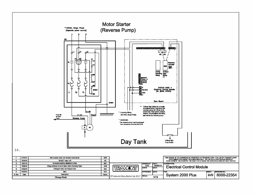
Main tank above Day Tank (TRS only) In instances where the main tank is above the Day Tank, the overflow line cannot be piped via gravity. The overflow line should not
be plugged. Instead, Tramont strongly recommends the use of a reverse pumping system to return excess fuel to the main
tank. Failure to use a reverse pumping system may result in a fuel spill should the Day Tank become overfilled. Reverse pumping
systems are available on Tramont TRS Series Day Tanks. See Tramont specification "Diesel Fuel Day Tank with Supply Pump and
Motor,” or contact Tramont Sales and Service for more information.
VENTS There is a 2” NPT normal vent fitting at the top rear of tank. This is an atmospheric vent and must be piped in a continuous upward
path with no traps. In installations with a main tank the normal vent must be piped higher than the main tank fuel level. The normal
vent should be vented outside any enclosed spaces. The appropriate vent cap is available from Tramont Manufacturing, or users may
provide their own.
!WARNING!
DO NOT PLUG THE NORMAL VENT. THIS IS AN ATMOSPHERIC TANK ONLY AND IS NOT TO BE OPERATED UNDER
PRESSURE.
The tank also includes an NPT fitting for an emergency vent. The fitting will range in size from 2" to 5". Tanks with a sealed rupture
basin also will include an emergency vent fitting on the containment area. The emergency vent fittings may not be plugged. The
appropriate vent cap is available from Tramont Manufacturing, or users may provide their own. This vent is designed to open should
the tank become suddenly pressurized (in a fire, for example). Requirements for piping the emergency vent may vary by location.
Consult local codes on piping, vent caps, vent location and other requirements.
DRAIN Day Tanks less than 300 gallons include a 3/8" NPT drain fitting. Tanks 300 gallons or larger include a 1" NPT drain fitting. On day
tanks without a basin the drain fitting connects directly to the tank. On tanks with a basin the drain is connected to the containment
area only. The tank is shipped with the drain fitting plugged. This plug may become loose during shipping. It is the installer's
responsibility to verify the integrity of the drain and all other connections. In installations with a main tank the drain may be plumbed
back to the main tank. An optional drain petcock or ball valve is available from Tramont.
FUEL INLET: TRE & TRS ONLY The fuel inlet to the Day Tank is located on the pump. The standard Tramont Day Tank pump includes a 3/8" NPT female threaded
fitting. This fitting size may vary on optional pumps. Plumb the fuel supply line from the main tank to the Day Tank pump suction port.
Properly align the piping so that stress is not exerted on the pump. IMPORTANT NOTE: Fuel contamination can decrease pump life,
cause leaking valves and erratic gauge readings. Tramont strongly recommends the installation of a 100 mesh fuel strainer on the
pump inlet.
PIPING (TRE & TRS) Tramont Day Tank pumps are rated for 17' of vertical lift at sea level. Long horizontal runs, small diameter pipe and restrictions such
as elbows and valves can reduce lift. (See worksheet in "Design Considerations”, p.18). Leaks in the pipe line will reduce or eliminate
lift. Running the pump/motor with no fuel in the line may damage or destroy the pump and motor. Tramont strongly recommends that
manifold fuel lines be avoided. Tramont also strongly recommends that the incoming fuel line be primed as close to the pump as
possible prior to start-up.
TESTING The tank has been factory leak-tested at 3 - 5 PSIG per UL-142 requirements. All lines to and from the day tank should be pressure
tested for leaks. If they are available, close shutoff valves at both ends of the piping and apply pressure to desired levels. Lines that
have only gravity flow should be tested to twice the head pressure that would exist if the lower end of the line were plugged and the
line was filled with oil. Note: 2.68' of head = 1 PSIG.
!WARNING!
WHEN TESTING THE FUEL LINES DO NOT ALLOW THE TANK ITSELF TO BECOME PRESSURIZED IN EXCESS OF 5 PSIG.
EXCESS PRESSURE MAY DAMAGE THE TANK.
MECHANICAL INSPECTION Verify that all valves are open and all lines are pressure tested and clear. Verify that the installation is in accordance with mechanical
specifications and all local building codes. Day Tank users, installers and specifying engineers should be familiar with NFPA 30 and
37, UL-142, local codes and any other applicable codes.
TRS Series Day Tank
Tramont Manufacturing 3701 N. Humboldt Blvd. Milwaukee, WI 53212
Phone: 414-967-8800 Fax: 414-967-8811 [email protected] www.tramont.com © Tramont Manufacturing June 2017
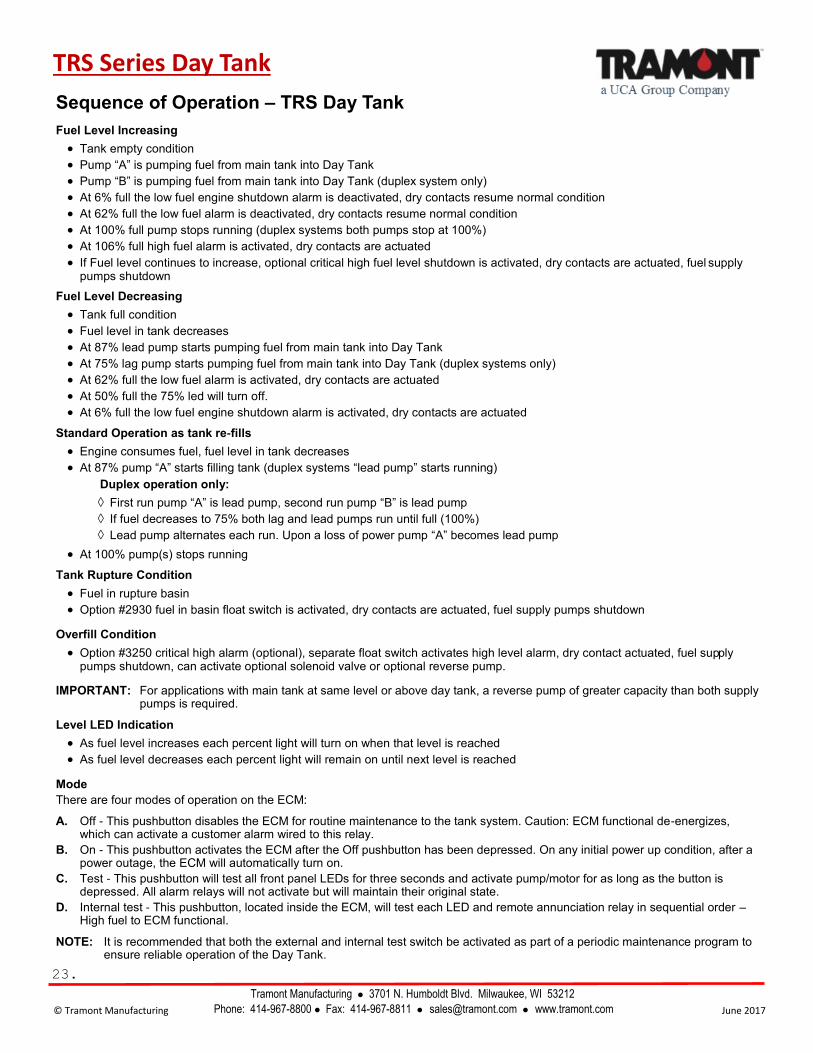
Sequence of Operation – TRS Day Tank
Fuel Level Increasing
• Tank empty condition
• Pump “A” is pumping fuel from main tank into Day Tank
• Pump “B” is pumping fuel from main tank into Day Tank (duplex system only)
• At 6% full the low fuel engine shutdown alarm is deactivated, dry contacts resume normal condition
• At 62% full the low fuel alarm is deactivated, dry contacts resume normal condition
• At 100% full pump stops running (duplex systems both pumps stop at 100%)
• At 106% full high fuel alarm is activated, dry contacts are actuated
• If Fuel level continues to increase, optional critical high fuel level shutdown is activated, dry contacts are actuated, fuel supply pumps shutdown
Fuel Level Decreasing
• Tank full condition
• Fuel level in tank decreases
• At 87% lead pump starts pumping fuel from main tank into Day Tank
• At 75% lag pump starts pumping fuel from main tank into Day Tank (duplex systems only)
• At 62% full the low fuel alarm is activated, dry contacts are actuated
• At 50% full the 75% led will turn off.
• At 6% full the low fuel engine shutdown alarm is activated, dry contacts are actuated
Standard Operation as tank re-fills
• Engine consumes fuel, fuel level in tank decreases
• At 87% pump “A” starts filling tank (duplex systems “lead pump” starts running)
Duplex operation only:
First run pump “A” is lead pump, second run pump “B” is lead pump
If fuel decreases to 75% both lag and lead pumps run until full (100%)
Lead pump alternates each run. Upon a loss of power pump “A” becomes lead pump
• At 100% pump(s) stops running
Tank Rupture Condition
• Fuel in rupture basin
• Option #2930 fuel in basin float switch is activated, dry contacts are actuated, fuel supply pumps shutdown
Overfill Condition
• Option #3250 critical high alarm (optional), separate float switch activates high level alarm, dry contact actuated, fuel supply pumps shutdown, can activate optional solenoid valve or optional reverse pump.
IMPORTANT: For applications with main tank at same level or above day tank, a reverse pump of greater capacity than both supply pumps is required.
Level LED Indication
• As fuel level increases each percent light will turn on when that level is reached
• As fuel level decreases each percent light will remain on until next level is reached
Mode
There are four modes of operation on the ECM:
A. Off - This pushbutton disables the ECM for routine maintenance to the tank system. Caution: ECM functional de-energizes, which can activate a customer alarm wired to this relay.
B. On - This pushbutton activates the ECM after the Off pushbutton has been depressed. On any initial power up condition, after a power outage, the ECM will automatically turn on.
C. Test - This pushbutton will test all front panel LEDs for three seconds and activate pump/motor for as long as the button is depressed. All alarm relays will not activate but will maintain their original state.
D. Internal test - This pushbutton, located inside the ECM, will test each LED and remote annunciation relay in sequential order – High fuel to ECM functional.
NOTE: It is recommended that both the external and internal test switch be activated as part of a periodic maintenance program to ensure reliable operation of the Day Tank.
23.

Troubleshooting Tips: ECM Functional Light Flashing
Tramont TRS Series Day Tanks include a System 2000PLUS™ Electronic Control
Module (ECM) that operates the pumps and motors and monitors fuel level conditions.
One of the indicators on the unit is the ECM Functional Light. During normal operation
this will be illuminated a steady green. (Arrow A)
When this light is flashing it means that the ECM is receiving an “out of range
reading” from the fuel level sensor inside the tank. The sensor is located under
the ECM and is mounted to a plate on the 4.5” X 4.5” inspection opening.
When the ECM Functional Light is flashing, power is cut off to
the supply pumps. When this occurs the other LEDs may or may
not light up, depending upon the problem. Either way, when the
ECM Functional Light is flashing, the other alarms may not be
functioning.
If the ECM Functional Light is flashing, follow these steps to
identify the source of the problem:
1. Remove the four mounting nuts on the corners of the ECM
base. (Arrow B)
2. Tilt the ECM back to expose the inspection plate, being
careful not to dislodge any wires inside the ECM. (Arrow C)
The top of the sensor is visible in the middle of the plate.
3. Disconnect the two wires on the sensor. (Arrow D)
4. Remove the five mounting screws on the sensor (Arrow E)
and carefully lift the sensor out of the tank.
5. Measure the resistance with an ohm meter across the two terminals
on the sensor. The ECM is set up to detect >0 and <90 ohms,
where close to 0 is “empty” and close to 90 is “full.” Move the float
on the sensor all the way from the down” (empty) position to the
“up” (full) position. Monitor the readings while swinging the float
from empty to full. Watch for opens, shorts and sticky spots.
Anything outside the 0 to 90 range will shut down the system and
flash the EMC Functional Light.
Cleaning the fuel level sensor will often solve the problem. Follow
these steps:
1. Swing the float arm all the way to “full” or “empty.”
2. Blast compressed air or non-residue contact cleaner into the pivot
point. (Arrow F)
3. Swing the float arm all the way to the other end of its travel and repeat
Step 2.
4. Swing the arm through its full length of travel 15 to 20 times.
5. Repeat Steps 2 and 3.
6. Retest with the ohm meter per the above instructions.
7. If the readings are correct, reinsert the float sensor into the tank, affix the
mounting screws and reconnect the two wires. Carefully move the ECM
back into place and attach it to the top of the tank with the mounting nuts.
8. If the readings are not correct, you likely need to replace the sensor.
Contact Tramont for assistance.
TRS Series Day Tank
Tramont Manufacturing 3701 N. Humboldt Blvd. Milwaukee, WI 53212
Phone: 414-967-8800 Fax: 414-967-8811 [email protected] www.tramont.com © Tramont Manufacturing June 2017
Tramont
TRS Series
Day Tank.
E
B
A
D
F
C
24.
TRS Series Day Tank
Tramont Manufacturing 3701 N. Humboldt Blvd. Milwaukee, WI 53212
Phone: 414-967-8800 Fax: 414-967-8811 [email protected] www.tramont.com © Tramont Manufacturing June 2017
25.
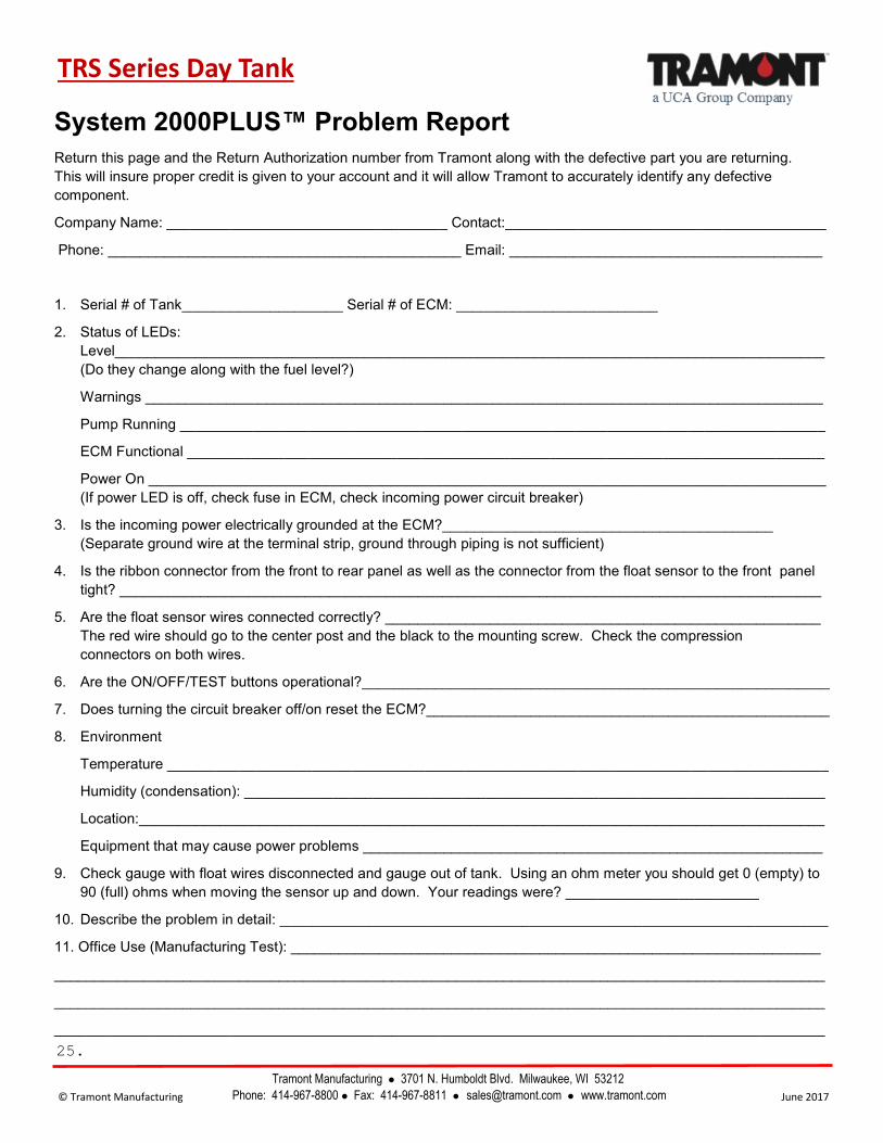
System 2000PLUS™ Problem Report
Return this page and the Return Authorization number from Tramont along with the defective part you are returning.
This will insure proper credit is given to your account and it will allow Tramont to accurately identify any defective
component.
Company Name: ___________________________________ Contact:________________________________________
Phone: ____________________________________________ Email: _______________________________________
1. Serial # of Tank____________________ Serial # of ECM: _________________________
2. Status of LEDs:
Level________________________________________________________________________________________
(Do they change along with the fuel level?)
Warnings ____________________________________________________________________________________
Pump Running ________________________________________________________________________________
ECM Functional _______________________________________________________________________________
Power On ____________________________________________________________________________________
(If power LED is off, check fuse in ECM, check incoming power circuit breaker)
3. Is the incoming power electrically grounded at the ECM?_________________________________________
(Separate ground wire at the terminal strip, ground through piping is not sufficient)
4. Is the ribbon connector from the front to rear panel as well as the connector from the float sensor to the front panel
tight? _______________________________________________________________________________________
5. Are the float sensor wires connected correctly? ______________________________________________________
The red wire should go to the center post and the black to the mounting screw. Check the compression
connectors on both wires.
6. Are the ON/OFF/TEST buttons operational?__________________________________________________________
7. Does turning the circuit breaker off/on reset the ECM?__________________________________________________
8. Environment
Temperature __________________________________________________________________________________
Humidity (condensation): ________________________________________________________________________
Location:_____________________________________________________________________________________
Equipment that may cause power problems _________________________________________________________
9. Check gauge with float wires disconnected and gauge out of tank. Using an ohm meter you should get 0 (empty) to
90 (full) ohms when moving the sensor up and down. Your readings were? ________________________
10. Describe the problem in detail: ____________________________________________________________________
11. Office Use (Manufacturing Test): __________________________________________________________________
________________________________________________________________________________________________
________________________________________________________________________________________________
________________________________________________________________________________________________
Day Tank
Tramont Manufacturing 3701 N. Humboldt Blvd. Milwaukee, WI 53212
Phone: 414-967-8800 Fax: 414-967-8811 [email protected] www.tramont.com © Tramont Manufacturing June 2017
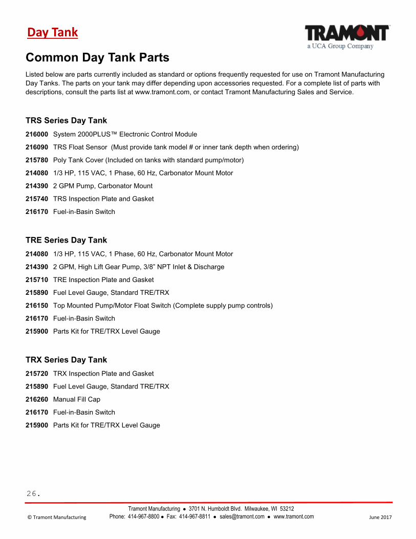
Common Day Tank Parts
Listed below are parts currently included as standard or options frequently requested for use on Tramont Manufacturing
Day Tanks. The parts on your tank may differ depending upon accessories requested. For a complete list of parts with
descriptions, consult the parts list at www.tramont.com, or contact Tramont Manufacturing Sales and Service.
TRS Series Day Tank
216000 System 2000PLUS™ Electronic Control Module
216090 TRS Float Sensor (Must provide tank model # or inner tank depth when ordering)
215780 Poly Tank Cover (Included on tanks with standard pump/motor)
214080 1/3 HP, 115 VAC, 1 Phase, 60 Hz, Carbonator Mount Motor
214390 2 GPM Pump, Carbonator Mount
215740 TRS Inspection Plate and Gasket
216170 Fuel-in-Basin Switch
TRE Series Day Tank
214080 1/3 HP, 115 VAC, 1 Phase, 60 Hz, Carbonator Mount Motor
214390 2 GPM, High Lift Gear Pump, 3/8” NPT Inlet & Discharge
215710 TRE Inspection Plate and Gasket
215890 Fuel Level Gauge, Standard TRE/TRX
216150 Top Mounted Pump/Motor Float Switch (Complete supply pump controls)
216170 Fuel-in-Basin Switch
215900 Parts Kit for TRE/TRX Level Gauge
TRX Series Day Tank
215720 TRX Inspection Plate and Gasket
215890 Fuel Level Gauge, Standard TRE/TRX
216260 Manual Fill Cap
216170 Fuel-in-Basin Switch
215900 Parts Kit for TRE/TRX Level Gauge
26.
Tramont Manufacturing ● 3701 N. Humboldt Blvd., Milwaukee WI 53212 ● P: 414-967-8800 ● F: 414-967-8811 ● www.tramont.com
© Tramont Manufacturing June 2017
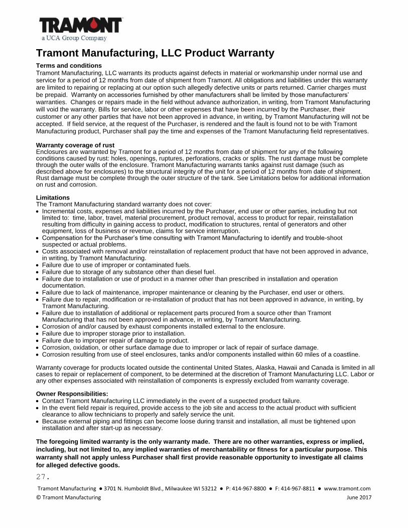
Tramont Manufacturing, LLC Product Warranty
Terms and conditions Tramont Manufacturing, LLC warrants its products against defects in material or workmanship under normal use and service for a period of 12 months from date of shipment from Tramont. All obligations and liabilities under this warranty are limited to repairing or replacing at our option such allegedly defective units or parts returned. Carrier charges must be prepaid. Warranty on accessories furnished by other manufacturers shall be limited by those manufacturers’ warranties. Changes or repairs made in the field without advance authorization, in writing, from Tramont Manufacturing will void the warranty. Bills for service, labor or other expenses that have been incurred by the Purchaser, their customer or any other parties that have not been approved in advance, in writing, by Tramont Manufacturing will not be accepted. If field service, at the request of the Purchaser, is rendered and the fault is found not to be with Tramont Manufacturing product, Purchaser shall pay the time and expenses of the Tramont Manufacturing field representatives. Warranty coverage of rust Enclosures are warranted by Tramont for a period of 12 months from date of shipment for any of the following conditions caused by rust: holes, openings, ruptures, perforations, cracks or splits. The rust damage must be complete through the outer walls of the enclosure. Tramont Manufacturing warrants tanks against rust damage (such as described above for enclosures) to the structural integrity of the unit for a period of 12 months from date of shipment. Rust damage must be complete through the outer structure of the tank. See Limitations below for additional information on rust and corrosion. Limitations The Tramont Manufacturing standard warranty does not cover: • Incremental costs, expenses and liabilities incurred by the Purchaser, end user or other parties, including but not
limited to: time, labor, travel, material procurement, product removal, access to product for repair, reinstallation resulting from difficulty in gaining access to product, modification to structures, rental of generators and other equipment, loss of business or revenue, claims for service interruption.
• Compensation for the Purchaser’s time consulting with Tramont Manufacturing to identify and trouble-shoot suspected or actual problems.
• Costs associated with removal and/or reinstallation of replacement product that have not been approved in advance, in writing, by Tramont Manufacturing.
• Failure due to use of improper or contaminated fuels. • Failure due to storage of any substance other than diesel fuel. • Failure due to installation or use of product in a manner other than prescribed in installation and operation
documentation. • Failure due to lack of maintenance, improper maintenance or cleaning by the Purchaser, end user or others. • Failure due to repair, modification or re-installation of product that has not been approved in advance, in writing, by
Tramont Manufacturing. • Failure due to installation of additional or replacement parts procured from a source other than Tramont
Manufacturing that has not been approved in advance, in writing, by Tramont Manufacturing. • Corrosion of and/or caused by exhaust components installed external to the enclosure. • Failure due to improper storage prior to installation. • Failure due to improper repair of damage to product. • Corrosion, oxidation, or other surface damage due to improper or lack of repair of surface damage. • Corrosion resulting from use of steel enclosures, tanks and/or components installed within 60 miles of a coastline. Warranty coverage for products located outside the continental United States, Alaska, Hawaii and Canada is limited in all cases to repair or replacement of component, to be determined at the discretion of Tramont Manufacturing LLC. Labor or any other expenses associated with reinstallation of components is expressly excluded from warranty coverage. Owner Responsibilities: • Contact Tramont Manufacturing LLC immediately in the event of a suspected product failure. • In the event field repair is required, provide access to the job site and access to the actual product with sufficient
clearance to allow technicians to properly and safely service the unit. • Because external piping and fittings can become loose during transit and installation, all must be tightened upon
installation and after start-up as necessary. The foregoing limited warranty is the only warranty made. There are no other warranties, express or implied,
including, but not limited to, any implied warranties of merchantability or fitness for a particular purpose. This
warranty shall not apply unless Purchaser shall first provide reasonable opportunity to investigate all claims
for alleged defective goods.
27.