Embed Size (px)
Citation preview
1
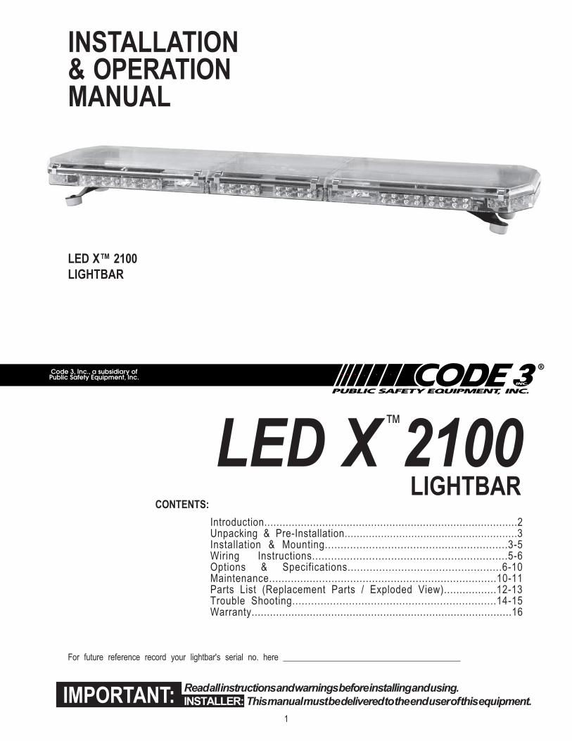
INSTALLATION& OPERATIONMANUAL
LED X™ 2100
LIGHTBAR
Read all instructions and warnings before installing and using.
INSTALLER: This manual must be delivered to the end user of this equipment.IMPORTANT:
Introduction...................................................................................2Unpacking & Pre-Installation.........................................................3Installation & Mounting..........................................................3-5Wiring Instructions..............................................................5-6Options & Specifications.................................................6-10Maintenance.........................................................................10-11Parts List (Replacement Parts / Exploded View).................12-13Trouble Shooting.................................................................14-15Warranty.....................................................................................16
CONTENTS:
For future reference record your lightbar's serial no. here __________________________________________
LED X
™
2100LIGHTBAR
2
IntroductionThe LED XTM 2100 Light Bar is a light bar that is approximately 2" high, yet delivers unobstructed 360° warning and more signal
power and versatility than any other light bar of its size.
The low profile and aerodynamic lines reduce air drag, which results in fuel savings and stability at high speeds. This light bar has a
strong extruded internal frame, shock-resistant polycarbonate lenses, and warning signals that exceed SAE standards.
The LED X 2100 is designed on a modular basis, which means that the light bar can be customized to meet any requirement. The
LED X 2100 has room for numerous halogen, incandescent and LED options. While we do not recommend a light installed in every
location, the design of the LED X 2100 offers the ultimate flexibility in the location of warning and auxiliary lights.
The use of this or any warning device does not ensure that all drivers can or will observe or react to an
emergency warning signal. Never take the right-of-way for granted. It is your responsibility to be sure you can
proceed safely before entering an intersection, driving against traffic, responding at a high rate of speed, or
walking on or around traffic lanes.
The effectiveness of this warning device is highly dependent upon correct mounting and wiring. Read and
follow the manufacturer’s instructions before installing or using this device. The vehicle operator should insure
daily that all features of the device operate correctly. In use, the vehicle operator should insure the projection
of the warning signal is not blocked by vehicle components (i.e.: open trunks or compartment doors), people,
vehicles, or other obstructions.
This equipment is intended for use by authorized personnel only. It is the user’s responsibility to understand
and obey all laws regarding emergency warning devices. The user should check all applicable city, state and
federal laws and regulations.
Code 3, Inc., assumes no liability for any loss resulting from the use of this warning device.
Proper installation is vital to the performance of this warning device and the safe operation of the emergency
vehicle. It is important to recognize that the operator of the emergency vehicle is under psychological and
physiological stress caused by the emergency situation. The warning device should be installed in such a
manner as to: A) Not reduce the output performance of the system, B) Place the controls within convenient
reach of the operator so that he can operate the system without losing eye contact with the roadway.
Emergency warning devices often require high electrical voltages and/or currents. Properly protect and use
caution around live electrical connections. Grounding or shorting of electrical connections can cause high
current arcing, which can cause personal injury and/or severe vehicle damage, including fire.
PROPER INSTALLATION COMBINED WITH OPERATOR TRAINING IN THE PROPER USE OF EMER-
GENCY WARNING DEVICES IS ESSENTIAL TO INSURE THE SAFETY OF EMERGENCY PERSONNEL
AND THE PUBLIC.
WARNING!
!
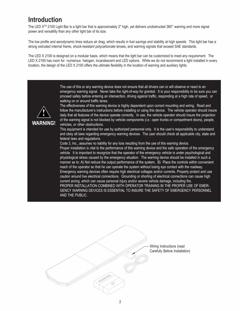
Wiring Instructions (read
Carefully Before Installation)
3
Unpacking & Pre-installationCarefully remove the light bar and place it on a flat surface, taking care not to scratch the lenses or damage the cable coming out of
the bottom. Examine the unit for transit damage, broken lamps, etc. Report any damage to the carrier and keep the shipping carton.
Standard light bars are built to operate on 12 volt D.C. negative ground (earth) vehicles. If you have an electrical system other than
12 volt D.C. negative ground (earth), and have not ordered a specially wired light bar, contact the factory for instructions.
Test the unit before installation. To test, touch the black wire to the ground (earth) and the other wires to +12 volts D.C., in
accordance with the instructions attached to the cable (an automotive battery is preferable for this test). A battery charger may be
used, but please note that some electronic options (flashers, stingrays, etc.) may not operate normally when powered by a battery
charger. If problems occur at this point, contact the factory.
Installation & Mounting
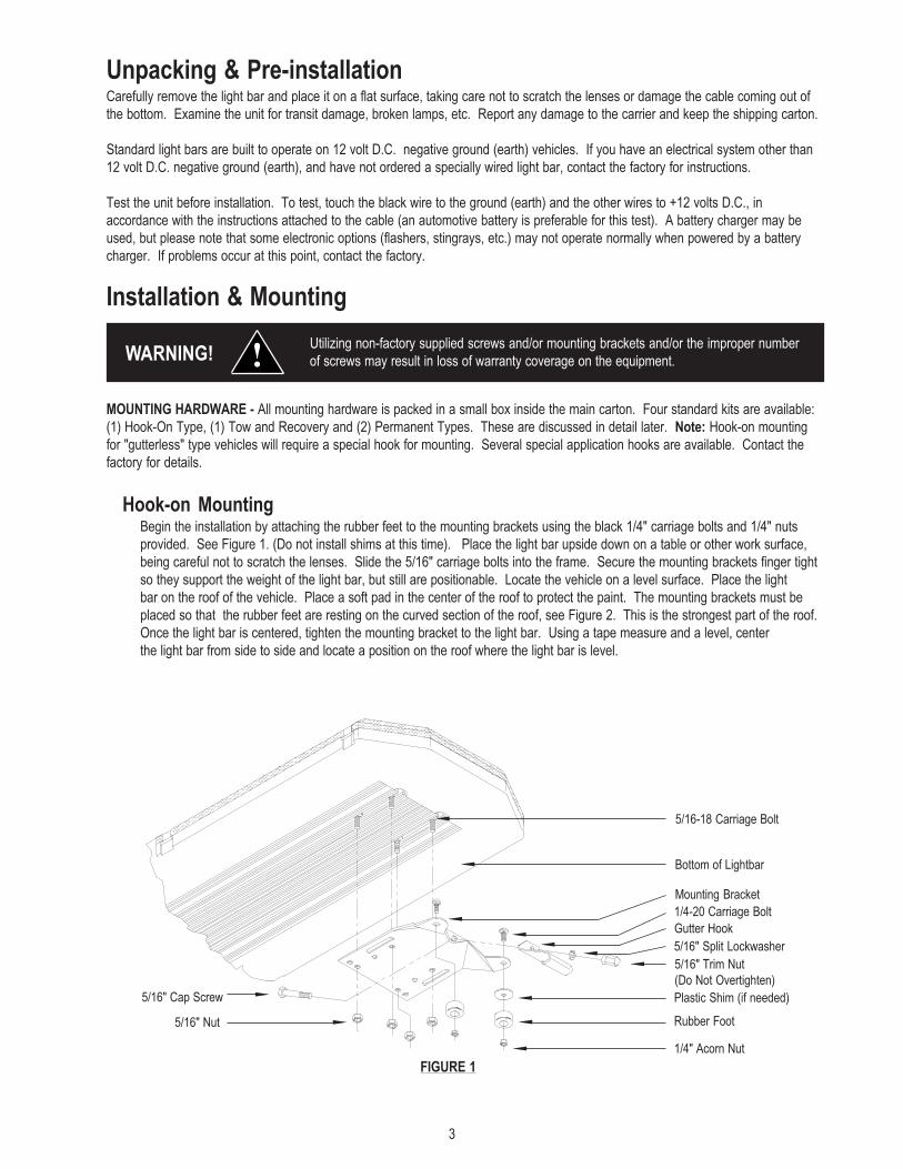
MOUNTING HARDWARE - All mounting hardware is packed in a small box inside the main carton. Four standard kits are available:
(1) Hook-On Type, (1) Tow and Recovery and (2) Permanent Types. These are discussed in detail later. Note: Hook-on mounting
for "gutterless" type vehicles will require a special hook for mounting. Several special application hooks are available. Contact the
factory for details.
Utilizing non-factory supplied screws and/or mounting brackets and/or the improper number
of screws may result in loss of warranty coverage on the equipment.WARNING! !
Mounting Bracket
Bottom of Lightbar
1/4-20 Carriage Bolt
5/16" Split Lockwasher
5/16" Trim Nut
(Do Not Overtighten)
Plastic Shim (if needed)
Rubber Foot
1/4" Acorn Nut
5/16" Cap Screw
5/16" Nut
FIGURE 1
Hook-on MountingBegin the installation by attaching the rubber feet to the mounting brackets using the black 1/4" carriage bolts and 1/4" nuts
provided. See Figure 1. (Do not install shims at this time). Place the light bar upside down on a table or other work surface,
being careful not to scratch the lenses. Slide the 5/16" carriage bolts into the frame. Secure the mounting brackets finger tight
so they support the weight of the light bar, but still are positionable. Locate the vehicle on a level surface. Place the light
bar on the roof of the vehicle. Place a soft pad in the center of the roof to protect the paint. The mounting brackets must be
placed so that the rubber feet are resting on the curved section of the roof, see Figure 2. This is the strongest part of the roof.
Once the light bar is centered, tighten the mounting bracket to the light bar. Using a tape measure and a level, center
the light bar from side to side and locate a position on the roof where the light bar is level.
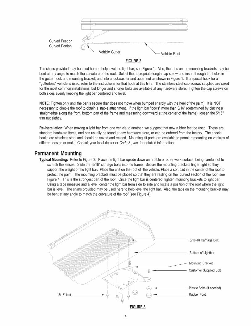
Gutter Hook
5/16-18 Carriage Bolt
4
Mounting Bracket
5/16-18 Carriage Bolt
Customer Supplied Bolt
Plastic Shim (if needed)
Rubber Foot5/16" Nut
FIGURE 3
Bottom of Lightbar
FIGURE 2
Vehicle RoofVehicle Gutter
Curved Feet on
Curved Portion
The shims provided may be used here to help level the light bar, see Figure 1. Also, the tabs on the mounting brackets may be
bent at any angle to match the curvature of the roof. Select the appropriate length cap screw and insert through the holes in
the gutter hook and mounting bracket, and into a lockwasher and acorn nut as shown in Figure 1. If a special hook for a
"gutterless" vehicle is used, refer to the instructions for that hook at this time. The stainless steel cap screws supplied are sized
for the most common installations, but longer and shorter bolts are available at any hardware store. Tighten the cap screws on
both sides evenly keeping the light bar centered and level.
NOTE: Tighten only until the bar is secure (bar does not move when bumped sharply with the heel of the palm). It is NOT
necessary to dimple the roof to obtain a stable attachment. If the light bar "bows" more than 3/16" (determined by placing a
straightedge along the front, bottom part of the frame and measuring downward at the center of the frame), loosen the 5/16"
trim nut sightly.
Re-Installation: When moving a light bar from one vehicle to another, we suggest that new rubber feet be used. These are
standard hardware items, and can usually be found at any hardware store, or can be ordered from the factory. The special
hooks are stainless steel and should be saved and reused. Mounting kit parts are available to permit remounting on vehicles of
different design or make. Consult your local dealer or Code 3 , Inc. for detailed information.
Permanent MountingTypical Mounting: Refer to Figure 3. Place the light bar upside down on a table or other work surface, being careful not to
scratch the lenses. Slide the 5/16" carriage bolts into the frame. Secure the mounting brackets finger tight so they
support the weight of the light bar. Place the unit on the roof of the vehicle. Place a soft pad in the center of the roof to
protect the paint. The mounting brackets must be placed so that they are resting on the curved section of the roof, see
Figure 4. This is the strongest part of the roof. Once the light bar is centered, tighten mounting brackets to light bar.
Using a tape measure and a level, center the light bar from side to side and locate a position of the roof where the light
bar is level. The shims provided may be used here to help level the light bar. Also, the tabs on the mounting bracket may
be bent at any angle to match the curvature of the roof (see Figure 4).
5
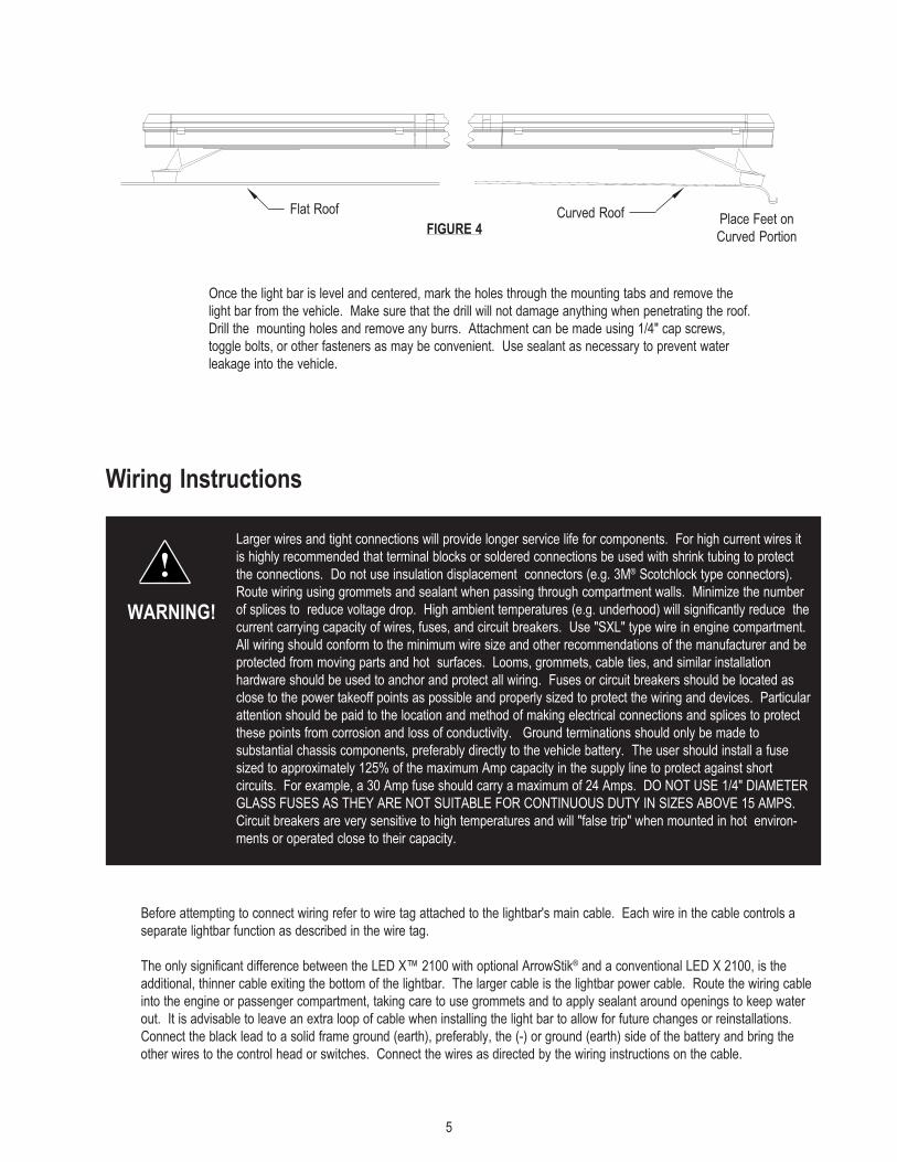
FIGURE 4
Once the light bar is level and centered, mark the holes through the mounting tabs and remove the
light bar from the vehicle. Make sure that the drill will not damage anything when penetrating the roof.
Drill the mounting holes and remove any burrs. Attachment can be made using 1/4" cap screws,
toggle bolts, or other fasteners as may be convenient. Use sealant as necessary to prevent water
leakage into the vehicle.
Wiring Instructions
Larger wires and tight connections will provide longer service life for components. For high current wires it
is highly recommended that terminal blocks or soldered connections be used with shrink tubing to protect
the connections. Do not use insulation displacement connectors (e.g. 3M® Scotchlock type connectors).
Route wiring using grommets and sealant when passing through compartment walls. Minimize the number
of splices to reduce voltage drop. High ambient temperatures (e.g. underhood) will significantly reduce the
current carrying capacity of wires, fuses, and circuit breakers. Use "SXL" type wire in engine compartment.
All wiring should conform to the minimum wire size and other recommendations of the manufacturer and be
protected from moving parts and hot surfaces. Looms, grommets, cable ties, and similar installation
hardware should be used to anchor and protect all wiring. Fuses or circuit breakers should be located as
close to the power takeoff points as possible and properly sized to protect the wiring and devices. Particular
attention should be paid to the location and method of making electrical connections and splices to protect
these points from corrosion and loss of conductivity. Ground terminations should only be made to
substantial chassis components, preferably directly to the vehicle battery. The user should install a fuse
sized to approximately 125% of the maximum Amp capacity in the supply line to protect against short
circuits. For example, a 30 Amp fuse should carry a maximum of 24 Amps. DO NOT USE 1/4" DIAMETER
GLASS FUSES AS THEY ARE NOT SUITABLE FOR CONTINUOUS DUTY IN SIZES ABOVE 15 AMPS.
Circuit breakers are very sensitive to high temperatures and will "false trip" when mounted in hot environ-
ments or operated close to their capacity.
WARNING!
!
Curved RoofFlat RoofPlace Feet on
Curved Portion
Before attempting to connect wiring refer to wire tag attached to the lightbar's main cable. Each wire in the cable controls a
separate lightbar function as described in the wire tag.
The only significant difference between the LED X™ 2100 with optional ArrowStik® and a conventional LED X 2100, is the
additional, thinner cable exiting the bottom of the lightbar. The larger cable is the lightbar power cable. Route the wiring cable
into the engine or passenger compartment, taking care to use grommets and to apply sealant around openings to keep water
out. It is advisable to leave an extra loop of cable when installing the light bar to allow for future changes or reinstallations.
Connect the black lead to a solid frame ground (earth), preferably, the (-) or ground (earth) side of the battery and bring the
other wires to the control head or switches. Connect the wires as directed by the wiring instructions on the cable.
6
This Product contains high intensity LED devices. To prevent eye damage, DO NOT stare
into light beam at close range.WARNING! !
L.E.D. Fusing Considerations
Although the average current draw per module is very low, due to the type of circuit used to power each module the instantaneous
peak current to a module can be significantly higher during low voltage conditions. To avoid prematurely blowing ATO style fuses
or tripping breakers it is recommended the following rule-of-thumb be used to size fuses or breakers. This is especially important in
lightbars with many LED modules running off a single fused source,
Minimum fuse size calculation:
1.5 x (number of modules being fused)
Example:
LED X 2100 Lightbar with 2 corner modules (2 per module) and 14 directional modules.
Minimum fuse requirement for single fuse - 1.5 (2+2+14) = 27A minimum
OPTIONS & SPECIFICATIONSMany options are available for the LED X 2100. This section is designed to describe the function of the various LED X 2100
options.
LED WARNING MODULES
Dim Operation
Lightbar LED modules are equipped with a low power "Dimming" mode. Dimming will be controlled by applying +12V by
way of the appropriate wire(color) in the wire harness/wire list. When DIM is engaged the LED's will operate in a
reduced power mode.
The Dim setting reduces the light output of emergency warning lights reducing the effectiveness of
them especially in brightly lit areas. Failure to use adequate light for the circumstances can cause
motorists to fail to see the emergency vehicle and lead to serious personal injury or death. Never
use the DIM setting in a brightly lit area. Use of the DIM setting may cause emergency lights to not
comply with applicable emergency warning light standards. Use caution when using the DIM setting
to assure that motorists can clearly see the emergency vehicle.
!
WARNING!
For safety purposes, the corner modules in lightbars are not connected to the dimming circuit.
This ensures that when corner modules are turned on, full 360 degree coverage and
compliance with SAE warning light standards is provided.
The DIM control wires(two white wires) located on each of the modules are connected from one module to
the next. To disable the dimming function on a particular module, disconnect the white wires. Then
reconnect the white wire to the white wire on another module that has dimming enabled.
- Refer to the control head manual packaged with the lightbar for control
head installation and operation instruction.
Arrowstik® / Narrowstik®OPTIONAL HALOGEN ARROWSTIK® (7-wire) / L.E.D. NARROWSTIK® (11-wire) WIRING AND CONTROL HEAD INSTALLATION -
After installation of the lightbar, route the smaller of the two power cables through the vehicle to the location chosen for the control
head. Cut the cable to length and strip back the outer insulation to expose the seven or eleven colored wires. Strip back 1/8” - 1/4” of
colored insulation from each of the wires in the cable. Connect these wires to the seven position / eleven position terminal plug
enclosed in the user parts bag, according to the diagram on the bottom of the control head.
7
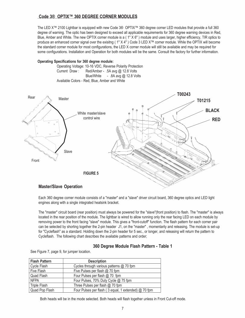
Code 3® OPTIX™ 360 DEGREE CORNER MODULES
The LED X™ 2100 Lightbar is equipped with new Code 3® OPTIX™ 360 degree corner LED modules that provide a full 360
degree of warning. The optic has been designed to exceed all applicable requirements for 360 degree warning devices in Red,
Blue, Amber and White. The new OPTIX corner module is a ( 1" X 6" ) module and uses larger, higher efficiency, TIR optics to
produce an enhanced corner signal over the exisitng ( 1" X 4" ) Code 3 LED X™ corner module. While the OPTIX will become
the standard corner module for most configurations, the LED X corner module will still be available and may be required for
some configurations. Installation and Operation for both modules will be the same. Consult the factory for further information.
Operating Specifications for 360 degree module:
Operating Voltage: 10-16 VDC, Reverse Polarity Protection
Current Draw : Red/Amber - .5A avg @ 12.8 Volts
Blue/White - .8A avg @ 12.8 Volts
Available Colors - Red, Blue, Amber and White
Rear
Front
Slave
Master
Master/Slave Operation
Each 360 degree corner module consists of a "master" and a "slave" driver circuit board, 360 degree optics and LED light
engines along with a single integrated heatsink bracket.
The "master" circuit board (rear position) must always be powered for the "slave"(front position) to flash. The "master" is always
located in the rear position of the module. The lightbar is wired to allow running only the rear facing LED on each module by
removing power to the front facing "slave" module. This gives a "front-cutoff" function. The flash pattern for each corner pair
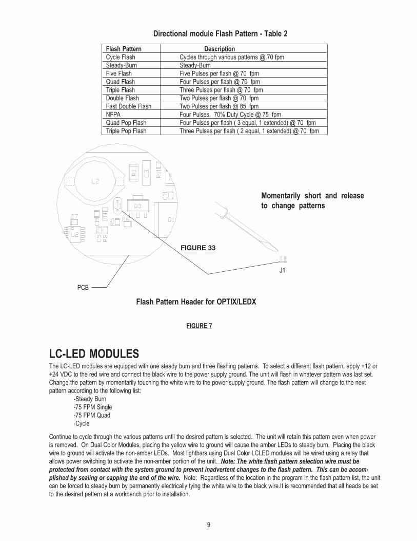
can be selected by shorting together the 2-pin header J1, on the "master" , momentarily and releasing. The module is set-up
for "Cycleflash" as a standard. Holding down the 2-pin header for 5 sec., or longer, and releasing will return the pattern to
Cycleflash. The following chart describes the available patterns and order;
White master/slave
control wire
360 Degree Module Flash Pattern - Table 1See Figure 7, page 9, for jumper location.
Flash Pattern Description
Cycle Flash Cycles through various patterns @ 70 fpm
Five Flash Five Pulses per flash @ 70 fpm
Quad Flash Four Pulses per flash @ 70 fpm
NFPA Four Pulses, 70% Duty Cycle @ 75 fpm
Triple Flash Three Pulses per flash @ 70 fpm
Quad Pop Flash Four Pulses per flash ( 3 equal, 1 extended) @ 70 fpm
Both heads will be in the mode selected. Both heads will flash together unless in Front Cut-off mode.
FIGURE 5
T00243
RED
BLACK
T01215
8
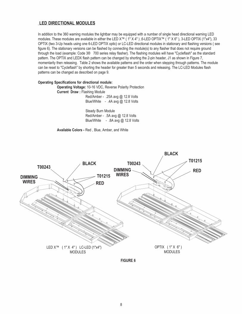
LED DIRECTIONAL MODULES
In addition to the 360 warning modules the lightbar may be equipped with a number of single head directional warning LED
modules. These modules are available in either the LED X™ ( 1" X 4" ) ,6-LED OPTIX™ ( 1" X 6" ), 3-LED OPTIX (1"x4"), 33
OPTIX (two 3-Up heads using one 6-LED OPTIX optic) or LC-LED directional modules in stationary and flashing versions ( see
figure 6). The stationary versions can be flashed by connecting the module(s) to any flasher that does not require ground
through the load (example: Code 3® 700 series relay flasher). The flashing modules will have "Cycleflash" as the standard
pattern. The OPTIX and LEDX flash pattern can be changed by shorting the 2-pin header, J1 as shown in Figure 7,
momentarily then releasing. Table 2 shows the available patterns and the order when stepping through patterns. The module
can be reset to "Cycleflash" by shorting the header for greater than 5 seconds and releasing. The LC-LED Modules flash
patterns can be changed as described on page 9.
Operating Specifications for directional module:
Operating Voltage: 10-16 VDC, Reverse Polarity Protection
Current Draw : Flashing Module
Red/Amber - .25A avg @ 12.8 Volts
Blue/White - .4A avg @ 12.8 Volts
Steady Burn Module
Red/Amber - .5A avg @ 12.8 Volts
Blue/White - .8A avg @ 12.8 Volts
Available Colors - Red , Blue, Amber, and White
BLACK
RED
T01215
T00243
FIGURE 6
BLACK
RED
T01215T00243
LED X™ ( 1" X 4" ) LC-LED (1"x4")
MODULES
OPTIX ( 1" X 6" )
MODULES
DIMMINGWIRES
DIMMINGWIRES
9
FIGURE 7
LC-LED MODULESThe LC-LED modules are equipped with one steady burn and three flashing patterns. To select a different flash pattern, apply +12 or
+24 VDC to the red wire and connect the black wire to the power supply ground. The unit will flash in whatever pattern was last set.
Change the pattern by momentarily touching the white wire to the power supply ground. The flash pattern will change to the next
pattern according to the following list:
-Steady Burn
-75 FPM Single
-75 FPM Quad
-Cycle
Continue to cycle through the various patterns until the desired pattern is selected. The unit will retain this pattern even when power
is removed. On Dual Color Modules, placing the yellow wire to ground will cause the amber LEDs to steady burn. Placing the black
wire to ground will activate the non-amber LEDs. Most lightbars using Dual Color LCLED modules will be wired using a relay that
allows power switching to activate the non-amber portion of the unit. Note: The white flash pattern selection wire must be
protected from contact with the system ground to prevent inadvertent changes to the flash pattern. This can be accom-
plished by sealing or capping the end of the wire. Note: Regardless of the location in the program in the flash pattern list, the unit
can be forced to steady burn by permanently electrically tying the white wire to the black wire.It is recommended that all heads be set
to the desired pattern at a workbench prior to installation.
Directional module Flash Pattern - Table 2
Flash Pattern Description
Cycle Flash Cycles through various patterns @ 70 fpm
Steady-Burn Steady-Burn
Five Flash Five Pulses per flash @ 70 fpm
Quad Flash Four Pulses per flash @ 70 fpm
Triple Flash Three Pulses per flash @ 70 fpm
Double Flash Two Pulses per flash @ 70 fpm
Fast Double Flash Two Pulses per flash @ 85 fpm
NFPA Four Pulses, 70% Duty Cycle @ 75 fpm
Quad Pop Flash Four Pulses per flash ( 3 equal, 1 extended) @ 70 fpm
Triple Pop Flash Three Pulses per flash ( 2 equal, 1 extended) @ 70 fpm
FIGURE 33
Flash Pattern Header for OPTIX/LEDX
J1
PCB
Momentarily short and release
to change patterns
10
WARNING!Lamps are extremely hot! Allow to cool completely before attempting to remove. Gloves and
eye protection should be worn when handling halogen lamps as they are pressurized and
accidental breakage can result in flying glass.!
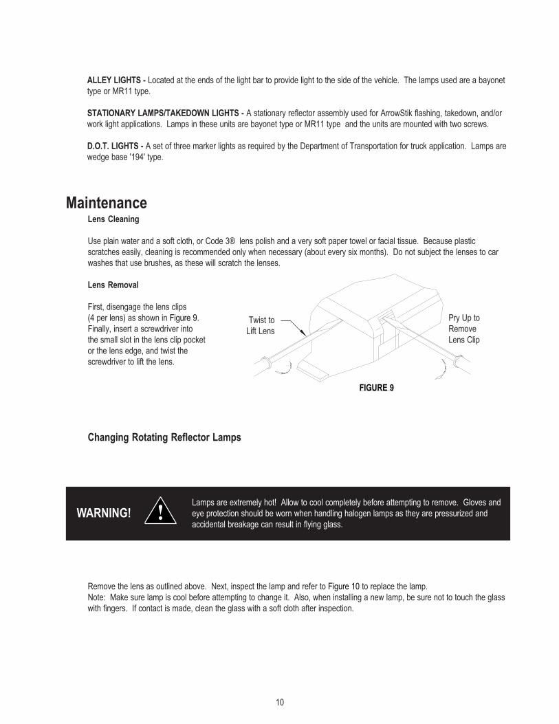
MaintenanceLens Cleaning
Use plain water and a soft cloth, or Code 3® lens polish and a very soft paper towel or facial tissue. Because plastic
scratches easily, cleaning is recommended only when necessary (about every six months). Do not subject the lenses to car
washes that use brushes, as these will scratch the lenses.
Lens Removal
First, disengage the lens clips
(4 per lens) as shown in Figure 9.
Finally, insert a screwdriver into
the small slot in the lens clip pocket
or the lens edge, and twist the
screwdriver to lift the lens.
Changing Rotating Reflector Lamps
FIGURE 9
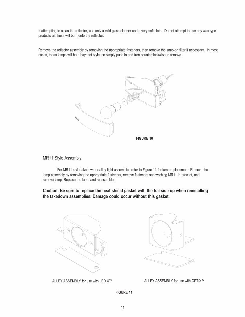
Remove the lens as outlined above. Next, inspect the lamp and refer to Figure 10 to replace the lamp.
Note: Make sure lamp is cool before attempting to change it. Also, when installing a new lamp, be sure not to touch the glass
with fingers. If contact is made, clean the glass with a soft cloth after inspection.
Twist to
Lift Lens
Pry Up to
Remove
Lens Clip
ALLEY LIGHTS - Located at the ends of the light bar to provide light to the side of the vehicle. The lamps used are a bayonet
type or MR11 type.
STATIONARY LAMPS/TAKEDOWN LIGHTS - A stationary reflector assembly used for ArrowStik flashing, takedown, and/or
work light applications. Lamps in these units are bayonet type or MR11 type and the units are mounted with two screws.
D.O.T. LIGHTS - A set of three marker lights as required by the Department of Transportation for truck application. Lamps are
wedge base '194' type.
11
FIGURE 10
If attempting to clean the reflector, use only a mild glass cleaner and a very soft cloth. Do not attempt to use any wax type
products as these will burn onto the reflector.
Remove the reflector assembly by removing the appropriate fasteners, then remove the snap-on filter if necessary. In most
cases, these lamps will be a bayonet style, so simply push in and turn counterclockwise to remove.
FIGURE 11
MR11 Style Assembly
For MR11 style takedown or alley light assemblies refer to Figure 11 for lamp replacement. Remove the
lamp assembly by removing the appropriate fasteners, remove fasteners sandwiching MR11 in bracket, and
remove lamp. Replace the lamp and reassemble.
Caution: Be sure to replace the heat shield gasket with the foil side up when reinstalling
the takedown assemblies. Damage could occur without this gasket.
ALLEY ASSEMBLY for use with OPTIX™ALLEY ASSEMBLY for use with LED X™
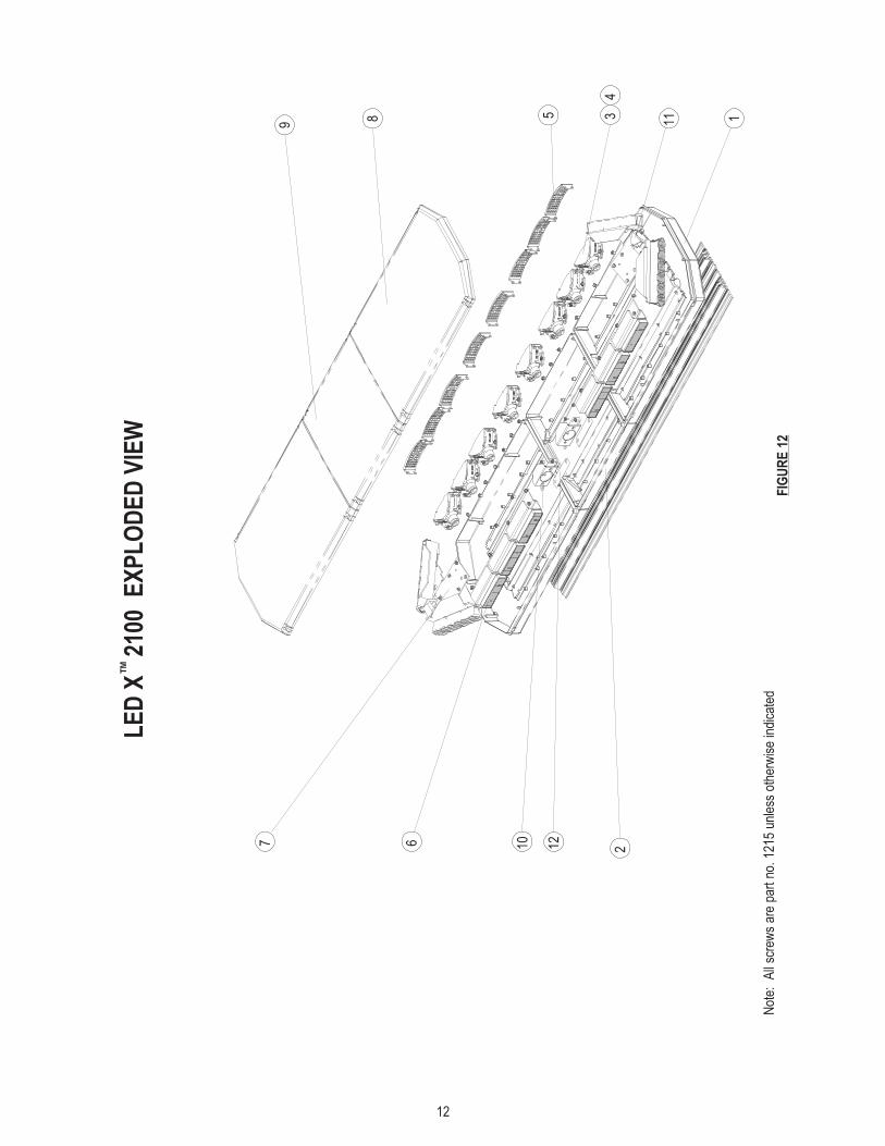
12
34
67 10 2
11 1
Not
e:
All
scre
ws
are
part
no.
121
5 un
less
oth
erw
ise
indi
cate
dF
IGU
RE
12
LE
D X
2
100
EX
PL
OD
ED
VIE
W
589
TM
12
13
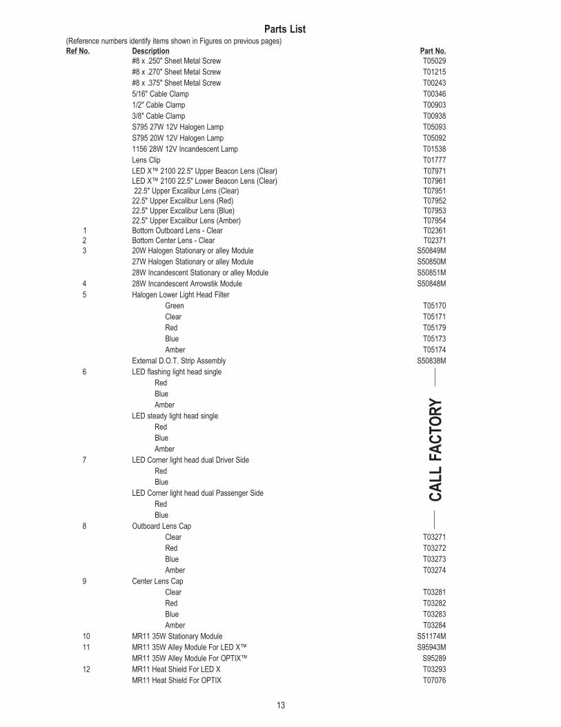
Parts List(Reference numbers identify items shown in Figures on previous pages)
Ref No. Description Part No.
#8 x .250" Sheet Metal Screw T05029
#8 x .270" Sheet Metal Screw T01215
#8 x .375" Sheet Metal Screw T00243
5/16" Cable Clamp T00346
1/2" Cable Clamp T00903
3/8" Cable Clamp T00938
S795 27W 12V Halogen Lamp T05093
S795 20W 12V Halogen Lamp T05092
1156 28W 12V Incandescent Lamp T01538
Lens Clip T01777
LED X™ 2100 22.5" Upper Beacon Lens (Clear) T07971
LED X™ 2100 22.5" Lower Beacon Lens (Clear) T07961
22.5" Upper Excalibur Lens (Clear) T07951
22.5" Upper Excalibur Lens (Red) T07952
22.5" Upper Excalibur Lens (Blue) T07953
22.5" Upper Excalibur Lens (Amber) T07954
1 Bottom Outboard Lens - Clear T02361
2 Bottom Center Lens - Clear T02371
3 20W Halogen Stationary or alley Module S50849M
27W Halogen Stationary or alley Module S50850M
28W Incandescent Stationary or alley Module S50851M
4 28W Incandescent Arrowstik Module S50848M
5 Halogen Lower Light Head Filter
Green T05170
Clear T05171
Red T05179
Blue T05173
Amber T05174
External D.O.T. Strip Assembly S50838M
6 LED flashing light head single
Red
Blue
Amber
LED steady light head single
Red
Blue
Amber
7 LED Corner light head dual Driver Side
Red
Blue
LED Corner light head dual Passenger Side
Red
Blue
8 Outboard Lens Cap
Clear T03271
Red T03272
Blue T03273
Amber T03274
9 Center Lens Cap
Clear T03281
Red T03282
Blue T03283
Amber T03284
10 MR11 35W Stationary Module S51174M
11 MR11 35W Alley Module For LED X™ S95943M
MR11 35W Alley Module For OPTIX™ S95289
12 MR11 Heat Shield For LED X T03293
MR11 Heat Shield For OPTIX T07076
CA
LL
FA
CT
OR
Y
14
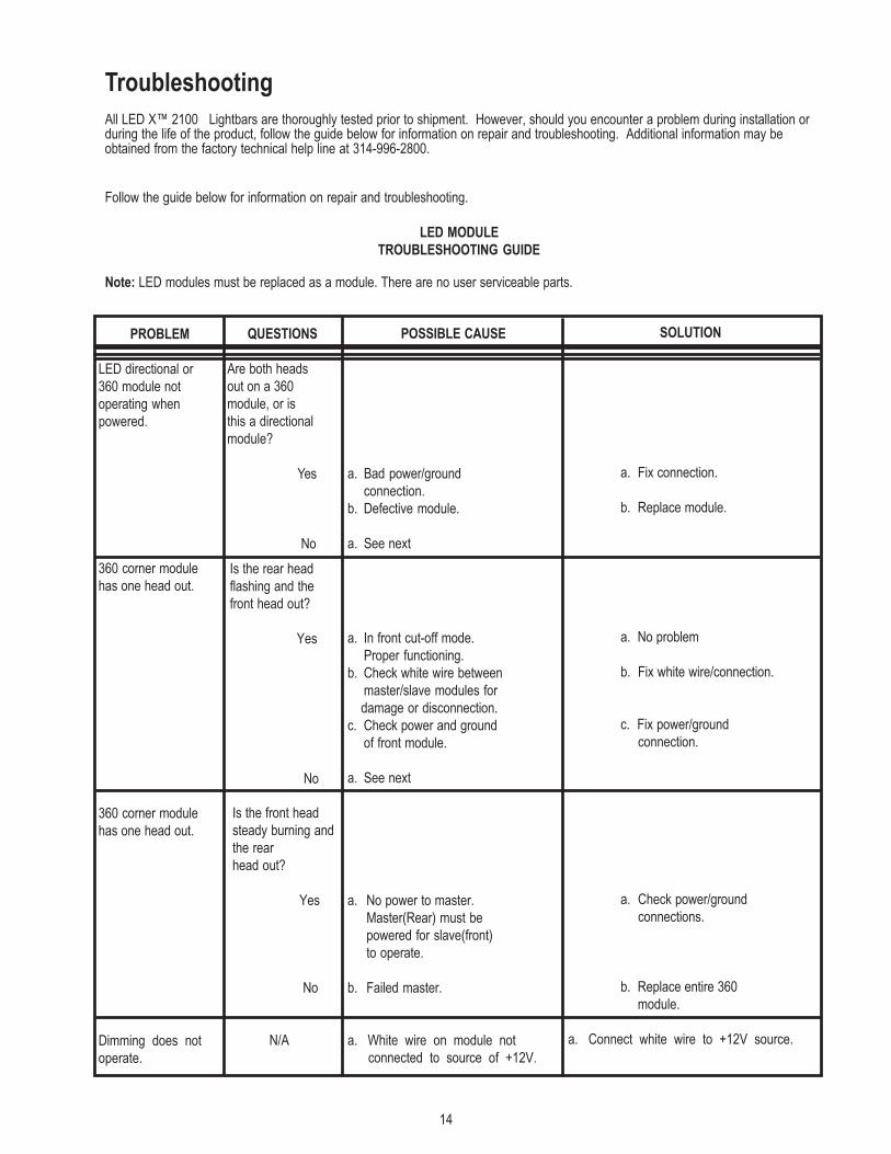
PROBLEM
LED directional or
360 module not
operating when
powered.
360 corner module
has one head out.
360 corner module
has one head out.
Dimming does not
operate.
POSSIBLE CAUSE
a. Bad power/ground
connection.
b. Defective module.
a. See next
a. In front cut-off mode.
Proper functioning.
b. Check white wire between
master/slave modules for
damage or disconnection.
c. Check power and ground
of front module.
a. See next
a. No power to master.
Master(Rear) must be
powered for slave(front)
to operate.
b. Failed master.
a. White wire on module not
connected to source of +12V.
SOLUTION
a. Fix connection.
b. Replace module.
a. No problem
b. Fix white wire/connection.
c. Fix power/ground
connection.
a. Check power/ground
connections.
b. Replace entire 360
module.
a. Connect white wire to +12V source.
Follow the guide below for information on repair and troubleshooting.
LED MODULE
TROUBLESHOOTING GUIDE
Troubleshooting
All LED X™ 2100 Lightbars are thoroughly tested prior to shipment. However, should you encounter a problem during installation orduring the life of the product, follow the guide below for information on repair and troubleshooting. Additional information may beobtained from the factory technical help line at 314-996-2800.
Note: LED modules must be replaced as a module. There are no user serviceable parts.
QUESTIONS
Are both heads
out on a 360
module, or is
this a directional
module?
Yes
No
Is the rear head
flashing and the
front head out?
Yes
No
Is the front head
steady burning and
the rear
head out?
Yes
No
N/A
15
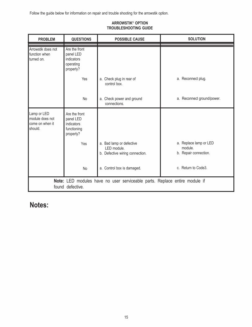
Follow the guide below for information on repair and trouble shooting for the arrowstik option.
ARROWSTIK® OPTION
TROUBLESHOOTING GUIDE
PROBLEM
Arrowstik does not
function when
turned on.
Lamp or LED
module does not
come on when it
should.
POSSIBLE CAUSE
a. Check plug in rear of
control box.
a. Check power and ground
connections.
a. Bad lamp or defective
LED module.
b. Defective wiring connection.
a. Control box is damaged.
SOLUTION
a. Reconnect plug.
a. Reconnect ground/power.
a. Replace lamp or LED
module.
b. Repair connection.
c. Return to Code3.
QUESTIONS
Are the front
panel LED
indicators
operating
properly?
Yes
No
Are the front
panel LED
indicators
functioning
properly?
Yes
No
Note: LED modules have no user serviceable parts. Replace entire module if
found defective.
Notes:
16
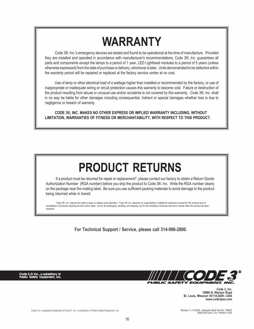
Revision 11, 01/2006 - Instruction Book Part No. T09453©2002-06 Code 3, Inc. Printed in USA
WARRANTYCode 3®, Inc.'s emergency devices are tested and found to be operational at the time of manufacture. Provided
they are installed and operated in accordance with manufacturer's recommendations, Code 3®, Inc. guarantees all
parts and components except the lamps to a period of 1 year, LED Lighthead modules to a period of 5 years (unless
otherwise expressed) from the date of purchase or delivery, whichever is later. Units demonstrated to be defective within
the warranty period will be repaired or replaced at the factory service center at no cost.
Use of lamp or other electrical load of a wattage higher than installed or recommended by the factory, or use of
inappropriate or inadequate wiring or circuit protection causes this warranty to become void. Failure or destruction of
the product resulting from abuse or unusual use and/or accidents is not covered by this warranty. Code 3®, Inc. shall
in no way be liable for other damages including consequential, indirect or special damages whether loss is due to
negligence or breach of warranty.
CODE 3®, INC. MAKES NO OTHER EXPRESS OR IMPLIED WARRANTY INCLUDING, WITHOUT
LIMITATION, WARRANTIES OF FITNESS OR MERCHANTABILITY, WITH RESPECT TO THIS PRODUCT.
PRODUCT RETURNSIf a product must be returned for repair or replacement*, please contact our factory to obtain a Return Goods
Authorization Number (RGA number) before you ship the product to Code 3®, Inc. Write the RGA number clearly
on the package near the mailing label. Be sure you use sufficient packing materials to avoid damage to the product
being returned while in transit.
*Code 3®, Inc. reserves the right to repair or replace at its discretion. Code 3®, Inc. assumes no responsibility or liability for expenses incurred for the removal and /or
reinstallation of products requiring service and/or repair.; nor for the packaging, handling, and shipping: nor for the handling of products returned to sender after the service has been
rendered.
Code 3, Inc.10986 N. Warson Road
St. Louis, Missouri 63114-2029—USAwww.code3pse.com
For Technical Support / Service, please call 314-996-2800.
Code 3 is a registered trademark of Code 3, Inc. a subsidiary of Public Safety Equipment, Inc.