Embed Size (px)
Citation preview

AccuFlowTM Vortex and AccuFlowTM HP+
Installation & Operation Manual
While every effort has been made to ensure the accuracy of this document, Raven Industries assumes no responsibility for omissions and errors. Nor is any liability assumed for damages resulting from the use of information contained herein.
Raven Industries shall not be responsible or liable for incidental or consequential damages or a loss of anticipated benefits or profits, work stoppage or loss, or impairment of data arising out of the use, or inability to use, this system or any of its components. Raven Industries shall not be held responsible for any modifications or repairs made outside our facilities, nor damages resulting from inadequate maintenance of this system.
As with all wireless and satellite signals, several factors may affect the availability and accuracy of wireless and satellite navigation and correction services (e.g. GPS, GNSS, SBAS, etc.). Therefore, Raven Industries cannot guarantee the accuracy, integrity, continuity, or availability of these services and cannot guarantee the ability to use Raven systems, or products used as components of systems, which rely upon the reception of these signals or availability of these services. Raven Industries accepts no responsibility for the use of any of these signals or services for other than the stated purpose.
Disclaimer
©Raven Industries, Inc. 2015
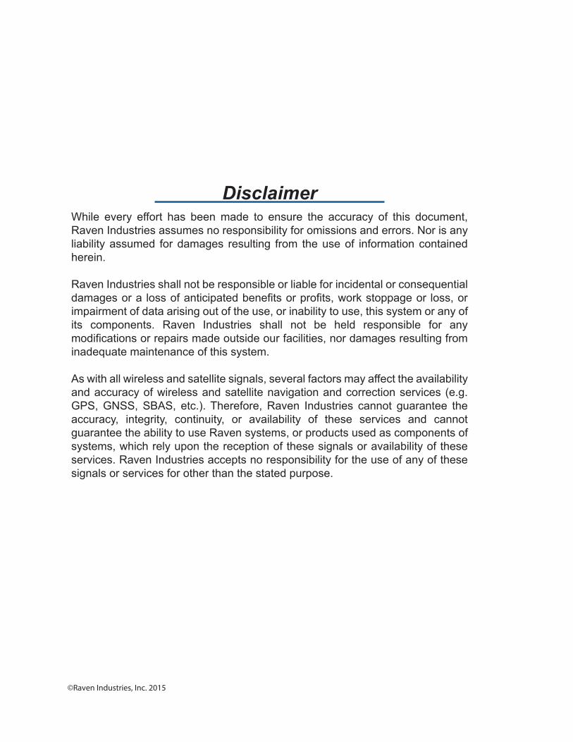
Table of Contents
Manual No. 016-0171-573 Rev. B i
Chapter 1 Important Safety Information................................................. 1
Instructions for Wire Routing ..................................................................................................... 3Instructions for Hose Routing .................................................................................................... 4Additional Safety Information .................................................................................................... 5
Electrical Safety ................................................................................................................... 5Discharging the AccuFlow™ System .................................................................................. 5
Before transporting the AccuFlow system or beginning service or maintenance: ............ 6
Chapter 2 Introduction............................................................................. 1
Overview ................................................................................................................................... 1AccuFlow™ Vortex and AccuFlow™ HP+ systems ............................................................. 1
Updates ..................................................................................................................................... 5
Chapter 3 AccuFlow™ Vortex and AccuFlow™ HP+ Installation ........ 7
Assembling the AccuFlow™ System ......................................................................................... 8Cooler Bracket Assembly .................................................................................................... 9Flow Meter and Outlet Manifold Assembly ........................................................................ 10Gauge Tree and Valve Assembly ...................................................................................... 12Attaching the Gauge Tree to the Cooler ............................................................................ 13Check Valve Assembly (For Multiple Section Valves Only) ............................................... 14Refrigerant Line Assembly ................................................................................................ 14
Inlet Manifold Assembly .......................................................................................................... 15Dual Inlet Manifold Assembly ............................................................................................ 15Dual Inlet Manifold Support Bracket Installation ................................................................ 16Single Inlet Manifold Assembly ......................................................................................... 17Single Inlet Manifold Support Bracket Installation ............................................................. 17
Installing a HP+ System .......................................................................................................... 18Installing Control Node: AccuFlow HP+ ............................................................................ 19Installing Pump Upgrade (Vortex to HP+ upgrade) ........................................................... 21Installing Hydraulic Valve ................................................................................................... 22Boost Pump Hydraulic Connections (HP+ System Only) .................................................. 23Mounting the AccuFlow™ System .................................................................................... 24Emergency Shut-off Rope Installation ............................................................................... 25
Vapor Port Assembly ............................................................................................................... 26AccuFlow™ Vapor and Applicator Plumbing Installation ......................................................... 26Bleed Line Hose Routing ........................................................................................................ 28Checking for System Leaks .................................................................................................... 30
Chapter 4 AccuFlow™ Vortex System (Non-Pump) Calibration and Operation ............................................................................... 31
Programming NH3 Rate Control ............................................................................................. 31Entering Boom Cal ............................................................................................................ 31
Table of Contents
ii AccuFlow™ Vortex and AccuFlow™ HP+ Installation & Operation Manual
Entering Speed Cal ...........................................................................................................31Entering Meter Cal .............................................................................................................32Adjusting Valve Cal ............................................................................................................33
Recommended Starting Valve Cals: ..............................................................................33Adjusting Rate Cal .............................................................................................................33
Calculating the Required Capacity .................................................................................33System Capacity Chart .................................................................................................. 34
AccuFlow NH3 Orifice Kit Instructions .....................................................................................35Overview ............................................................................................................................ 35Calculating the Required Capacity ....................................................................................35Installing and Orifice Hose Barb Fitting .............................................................................36
Charging the AccuFlow™ System ...........................................................................................36Verifying AccuFlow™ Operation .............................................................................................. 37
Chapter 5 AccuFlow™ HP+ Calibration and Operation...................... 39
Charging the AccuFlow™ HP+ System and Calibrating the Pressure Transducers (Pressure Cal) .......................................................................................................................................... 40Default Calibration Values (NH3 Pre-sets) .............................................................................. 41Programming HP+ Rate Control - Viper Pro ........................................................................... 42
Adjusting the Rate Cal .......................................................................................................46Calculating the Required Capacity .................................................................................46System Capacity Chart .................................................................................................. 47
Operating HP+ System in HP (NH3 Boost) Mode ...................................................................48Verifying AccuFlow HP+ Operation .........................................................................................49
Chapter 6 Service and Maintenance..................................................... 51
Discharging the AccuFlow™ System ................................................................................51Before transporting the AccuFlow system or beginning service or maintenance: .......... 52
Servicing and Storing the AccuFlow™ System .......................................................................54Maintaining the Vortex Cooler ...........................................................................................55
Strainer Maintenance Procedure .............................................................................................56Flow Meter Maintenance and Adjustment ...............................................................................57
Chapter 7 Troubleshooting ................................................................... 61
Pressure vs. Temperature .................................................................................................67Speed Sensor Extension Cable ...............................................................................................68
Testing the Speed Sensor Extension Cable ......................................................................68Flow Meter Extension Cable ...................................................................................................68
Testing the Flow Meter Cable ............................................................................................69
Chapter 8 System Diagram and Replacement Parts........................... 71
Standard AccuFlow™ Diagrams .............................................................................................71

Table of Contents
Manual No. 016-0171-573 Rev. B iii
Replacement Parts .................................................................................................................. 73

Table of Contents
iv AccuFlow™ Vortex and AccuFlow™ HP+ Installation & Operation Manual
CHAPTER
1
Manual No. 016-0171-573 Rev. B 1
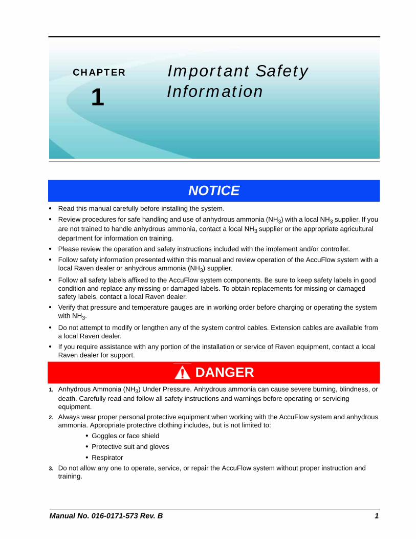
Chapter 1Important Safety Information
• Read this manual carefully before installing the system.
• Review procedures for safe handling and use of anhydrous ammonia (NH3) with a local NH3 supplier. If you are not trained to handle anhydrous ammonia, contact a local NH3 supplier or the appropriate agricultural department for information on training.
• Please review the operation and safety instructions included with the implement and/or controller.
• Follow safety information presented within this manual and review operation of the AccuFlow system with a local Raven dealer or anhydrous ammonia (NH3) supplier.
• Follow all safety labels affixed to the AccuFlow system components. Be sure to keep safety labels in good condition and replace any missing or damaged labels. To obtain replacements for missing or damaged safety labels, contact a local Raven dealer.
• Verify that pressure and temperature gauges are in working order before charging or operating the system with NH3.
• Do not attempt to modify or lengthen any of the system control cables. Extension cables are available from a local Raven dealer.
• If you require assistance with any portion of the installation or service of Raven equipment, contact a local Raven dealer for support.
1. Anhydrous Ammonia (NH3) Under Pressure. Anhydrous ammonia can cause severe burning, blindness, or death. Carefully read and follow all safety instructions and warnings before operating or servicing equipment.
2. Always wear proper personal protective equipment when working with the AccuFlow system and anhydrous ammonia. Appropriate protective clothing includes, but is not limited to:
• Goggles or face shield
• Protective suit and gloves
• Respirator
3. Do not allow any one to operate, service, or repair the AccuFlow system without proper instruction and training.
NOTICE
DANGER

Chapter 1
2 AccuFlow™ Vortex and AccuFlow™ HP+ Installation & Operation Manual
FIGURE 1. Danger Warning Decal Affixed to AccuFlow Vortex Cooler (P/N 039-0159-066)
1. Use caution when handling anhydrous ammonia (NH3) products.
a. Stand ‘up wind’ when working around anhydrous ammonia (NH3) and related equipment. Always keep anhydrous ammonia equipment away from buildings, livestock, and other people.
b. Anhydrous ammonia may cause sickness or death. Never work on NH3 equipment in confined spaces. Seek immediate medical attention if symptoms of illness occur during, or shortly after, use of anhydrous ammonia products.
c. Keep a source of clean water (at least five gallons) readily available while working with anhydrous ammonia. In case of exposure, flush exposed skin or eyes immediately with large quantities of water and seek immediate medical attention.
d. NH3 can be harmful to the environment if not used properly. Follow all local, state, and federal regulations regarding proper handling of anhydrous ammonia.
e. Always close nurse tank valve(s) when suspending field operation for any length of time.
2. Always remove the AccuFlow system from service before performing maintenance.
a. Thoroughly bleed all system lines and disconnect nurse tank hose before beginning service or maintenance.
b. Remove all NH3 from the system before disassembling or servicing. Verify gauge pressure is at zero, and no frost is present on any components before opening the system.
3. Use extreme caution when opening a previously pressurized system.
Before performing service or maintenance on the AccuFlow system, read and follow the instructions provided in the Discharging the AccuFlow™ System section on page 5 or page 51 to properly discharge the Vortex cooler and application lines.
• Remove rings and other jewelry to prevent electrical shorts or entanglement in moving parts.
CAUTION
REMOVE ALL AMMONIA FROM THESYSTEM BEFORE DISASSEMBLINGAND/OR SERVICING.
Manual No. 016-0171-573 Rev. B 3
Important Safety Information
1
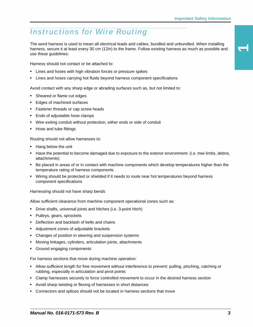
Instructions for Wire RoutingThe word harness is used to mean all electrical leads and cables, bundled and unbundled. When installing harness, secure it at least every 30 cm (12in) to the frame. Follow existing harness as much as possible and use these guidelines:
Harness should not contact or be attached to:
• Lines and hoses with high vibration forces or pressure spikes
• Lines and hoses carrying hot fluids beyond harness component specifications
Avoid contact with any sharp edge or abrading surfaces such as, but not limited to:
• Sheared or flame cut edges
• Edges of machined surfaces
• Fastener threads or cap screw heads
• Ends of adjustable hose clamps
• Wire exiting conduit without protection, either ends or side of conduit
• Hose and tube fittings
Routing should not allow harnesses to:
• Hang below the unit
• Have the potential to become damaged due to exposure to the exterior environment. (i.e. tree limbs, debris, attachments)
• Be placed in areas of or in contact with machine components which develop temperatures higher than the temperature rating of harness components
• Wiring should be protected or shielded if it needs to route near hot temperatures beyond harness component specifications
Harnessing should not have sharp bends
Allow sufficient clearance from machine component operational zones such as:
• Drive shafts, universal joints and hitches (i.e. 3-point hitch)
• Pulleys, gears, sprockets
• Deflection and backlash of belts and chains
• Adjustment zones of adjustable brackets
• Changes of position in steering and suspension systems
• Moving linkages, cylinders, articulation joints, attachments
• Ground engaging components
For harness sections that move during machine operation:
• Allow sufficient length for free movement without interference to prevent: pulling, pinching, catching or rubbing, especially in articulation and pivot points
• Clamp harnesses securely to force controlled movement to occur in the desired harness section
• Avoid sharp twisting or flexing of harnesses in short distances
• Connectors and splices should not be located in harness sections that move
Chapter 1
4 AccuFlow™ Vortex and AccuFlow™ HP+ Installation & Operation Manual
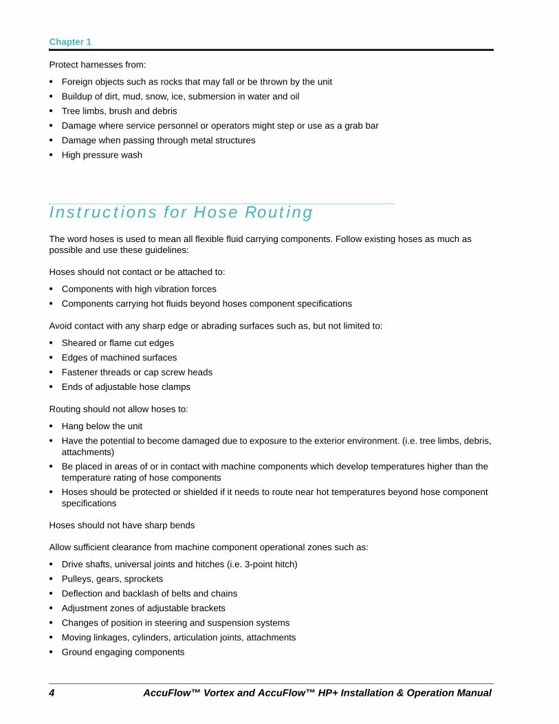
Protect harnesses from:
• Foreign objects such as rocks that may fall or be thrown by the unit
• Buildup of dirt, mud, snow, ice, submersion in water and oil
• Tree limbs, brush and debris
• Damage where service personnel or operators might step or use as a grab bar
• Damage when passing through metal structures
• High pressure wash
Instructions for Hose RoutingThe word hoses is used to mean all flexible fluid carrying components. Follow existing hoses as much as possible and use these guidelines:
Hoses should not contact or be attached to:
• Components with high vibration forces
• Components carrying hot fluids beyond hoses component specifications
Avoid contact with any sharp edge or abrading surfaces such as, but not limited to:
• Sheared or flame cut edges
• Edges of machined surfaces
• Fastener threads or cap screw heads
• Ends of adjustable hose clamps
Routing should not allow hoses to:
• Hang below the unit
• Have the potential to become damaged due to exposure to the exterior environment. (i.e. tree limbs, debris, attachments)
• Be placed in areas of or in contact with machine components which develop temperatures higher than the temperature rating of hose components
• Hoses should be protected or shielded if it needs to route near hot temperatures beyond hose component specifications
Hoses should not have sharp bends
Allow sufficient clearance from machine component operational zones such as:
• Drive shafts, universal joints and hitches (i.e. 3-point hitch)
• Pulleys, gears, sprockets
• Deflection and backlash of belts and chains
• Adjustment zones of adjustable brackets
• Changes of position in steering and suspension systems
• Moving linkages, cylinders, articulation joints, attachments
• Ground engaging components
Manual No. 016-0171-573 Rev. B 5
Important Safety Information
For hose sections that move during machine operation:
• Allow sufficient length for free movement without interference to prevent: pulling, pinching, catching or rubbing, especially in articulation and pivot points
• Clamp hoses securely to force controlled movement to occur in the desired hose section
• Avoid sharp twisting or flexing of hoses in short distances
Protect hoses from:
• Foreign objects such as rocks that may fall or be thrown by the unit
• Buildup of dirt, mud, snow, ice, submersion in water and oil
• Tree limbs, brush and debris
• Damage where service personnel or operators might step or use as a grab bar
• Damage when passing through metal structures
• High pressure wash
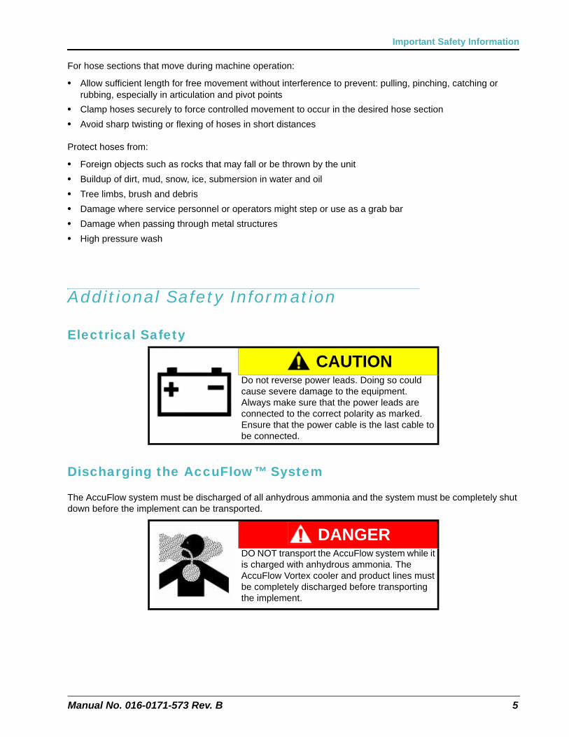
Additional Safety Information
Electrical Safety
Discharging the AccuFlow™ System
The AccuFlow system must be discharged of all anhydrous ammonia and the system must be completely shut down before the implement can be transported.
CAUTIONDo not reverse power leads. Doing so could cause severe damage to the equipment. Always make sure that the power leads are connected to the correct polarity as marked. Ensure that the power cable is the last cable to be connected.
DANGERDO NOT transport the AccuFlow system while it is charged with anhydrous ammonia. The AccuFlow Vortex cooler and product lines must be completely discharged before transporting the implement.
Chapter 1
6 AccuFlow™ Vortex and AccuFlow™ HP+ Installation & Operation Manual
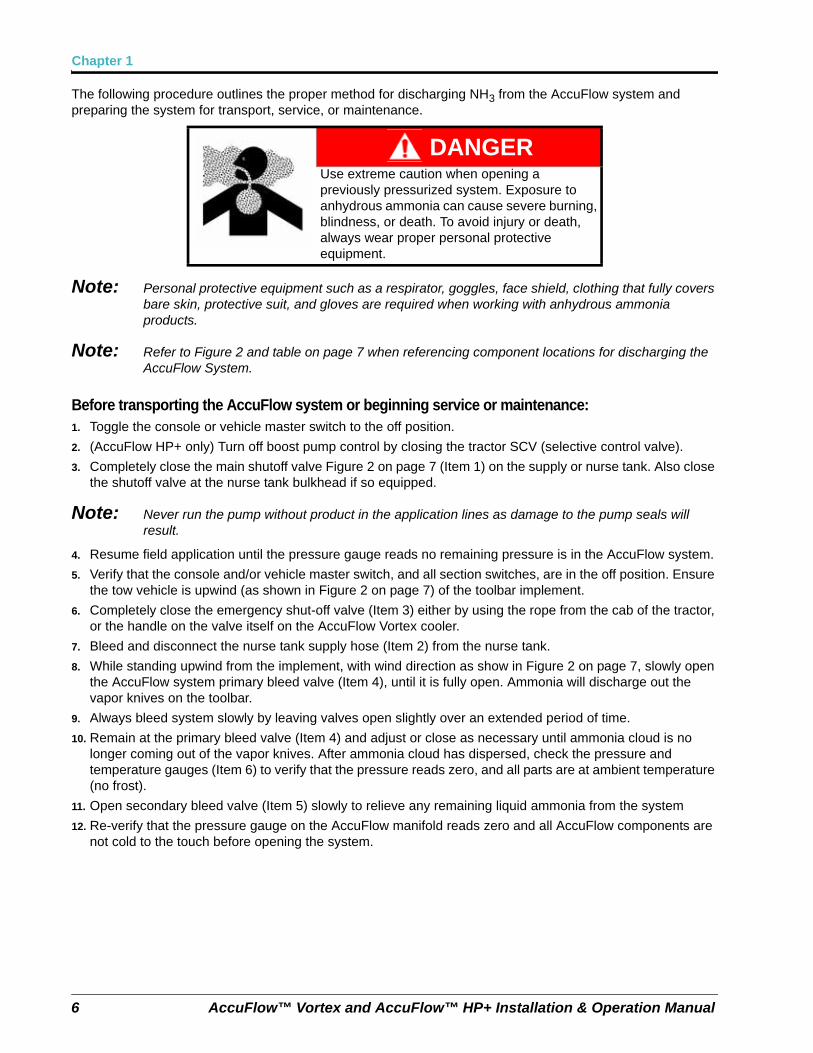
The following procedure outlines the proper method for discharging NH3 from the AccuFlow system and preparing the system for transport, service, or maintenance.
Note: Personal protective equipment such as a respirator, goggles, face shield, clothing that fully covers bare skin, protective suit, and gloves are required when working with anhydrous ammonia products.
Note: Refer to Figure 2 and table on page 7 when referencing component locations for discharging the AccuFlow System.
Before transporting the AccuFlow system or beginning service or maintenance:1. Toggle the console or vehicle master switch to the off position.
2. (AccuFlow HP+ only) Turn off boost pump control by closing the tractor SCV (selective control valve).
3. Completely close the main shutoff valve Figure 2 on page 7 (Item 1) on the supply or nurse tank. Also close the shutoff valve at the nurse tank bulkhead if so equipped.
Note: Never run the pump without product in the application lines as damage to the pump seals will result.
4. Resume field application until the pressure gauge reads no remaining pressure is in the AccuFlow system.
5. Verify that the console and/or vehicle master switch, and all section switches, are in the off position. Ensure the tow vehicle is upwind (as shown in Figure 2 on page 7) of the toolbar implement.
6. Completely close the emergency shut-off valve (Item 3) either by using the rope from the cab of the tractor, or the handle on the valve itself on the AccuFlow Vortex cooler.
7. Bleed and disconnect the nurse tank supply hose (Item 2) from the nurse tank.
8. While standing upwind from the implement, with wind direction as show in Figure 2 on page 7, slowly open the AccuFlow system primary bleed valve (Item 4), until it is fully open. Ammonia will discharge out the vapor knives on the toolbar.
9. Always bleed system slowly by leaving valves open slightly over an extended period of time.
10. Remain at the primary bleed valve (Item 4) and adjust or close as necessary until ammonia cloud is no longer coming out of the vapor knives. After ammonia cloud has dispersed, check the pressure and temperature gauges (Item 6) to verify that the pressure reads zero, and all parts are at ambient temperature (no frost).
11. Open secondary bleed valve (Item 5) slowly to relieve any remaining liquid ammonia from the system
12. Re-verify that the pressure gauge on the AccuFlow manifold reads zero and all AccuFlow components are not cold to the touch before opening the system.
DANGERUse extreme caution when opening a previously pressurized system. Exposure to anhydrous ammonia can cause severe burning, blindness, or death. To avoid injury or death, always wear proper personal protective equipment.
Manual No. 016-0171-573 Rev. B 7
Important Safety Information
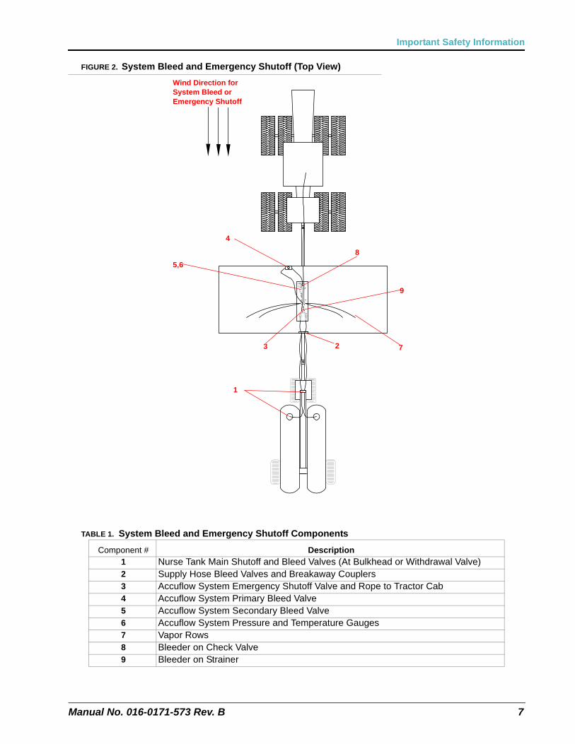
FIGURE 2. System Bleed and Emergency Shutoff (Top View)
TABLE 1. System Bleed and Emergency Shutoff Components
Component # Description1 Nurse Tank Main Shutoff and Bleed Valves (At Bulkhead or Withdrawal Valve)2 Supply Hose Bleed Valves and Breakaway Couplers3 Accuflow System Emergency Shutoff Valve and Rope to Tractor Cab4 Accuflow System Primary Bleed Valve5 Accuflow System Secondary Bleed Valve6 Accuflow System Pressure and Temperature Gauges7 Vapor Rows 8 Bleeder on Check Valve9 Bleeder on Strainer
Wind Direction for System Bleed or Emergency Shutoff
1
23
4
5,6
7
8
9
Chapter 1
8 AccuFlow™ Vortex and AccuFlow™ HP+ Installation & Operation Manual
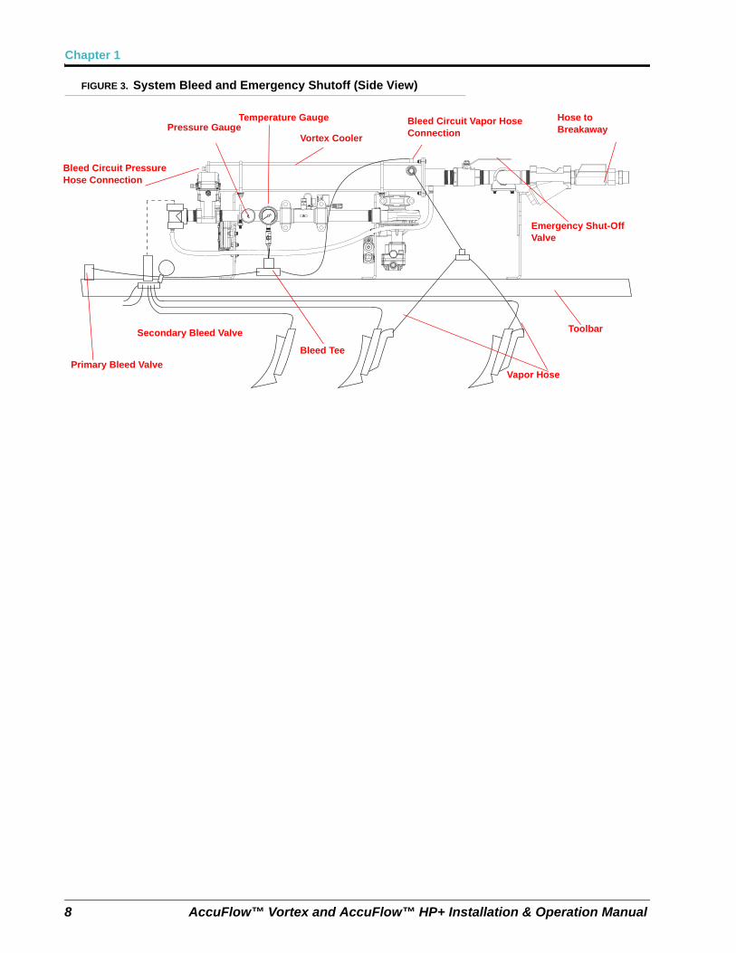
FIGURE 3. System Bleed and Emergency Shutoff (Side View)
Primary Bleed Valve
Secondary Bleed Valve
Bleed Tee
Vapor Hose
Toolbar
Hose to Breakaway
Bleed Circuit Pressure Hose Connection
Pressure GaugeTemperature Gauge
Vortex Cooler
Bleed Circuit Vapor Hose Connection
Emergency Shut-Off Valve
CHAPTER
2
Manual No. 016-0171-573 Rev. B 1
Chapter 2Introduction
OverviewThe Raven AccuFlow Vortex and HP+ system are designed to provide continuous and automatic control of anhydrous ammonia (NH3) applications via a Raven control system. The rate of application is monitored via a flow meter and controlled by the Raven console and control valve(s). The operator sets the target application rate in the Raven control console and the system automatically adjusts for vehicle speed and section status changes.
Note: To properly measure and control application, anhydrous ammonia must be in a liquid state when it passes through the flow meter. To remain liquid, anhydrous ammonia must be stored at a temperature of -28° F [-33° C] or kept under pressure at higher temperatures. To help ensure that the ammonia is in a liquid state as it passes through the flow meter the AccuFlow Vortex cooler uses a small amount of anhydrous ammonia from the system to reduce the temperature of the ammonia being applied.
The Raven AccuFlow Vortex system is available in two configurations to match the NH3 application needs:
• AccuFlow Vortex System
• AccuFlow HP+ High Performance System
AccuFlow™ Vortex and AccuFlow™ HP+ systems
The AccuFlow Vortex system is available in one or two valve configurations with a single Vortex cooler. The system is capable of applying anhydrous ammonia at rates up to 50 gallons per minute.
The AccuFlow HP+ system uses a boost pump to enhance the performance of the standard AccuFlow Vortex system to apply anhydrous ammonia in colder ambient temperatures, at higher rates, and at increased speeds. The AccuFlow HP+ system is only available in the single “fast valve” configuration. However, if a dual valve AccuFlow Vortex system is already present on the machine, the HP+ pump can be added to achieve rates over 50 gpm by using the pump to boost system pressure to the application lines. Refer to chapter 5 page 46 for operating Vortex system in NH3 Boost mode.
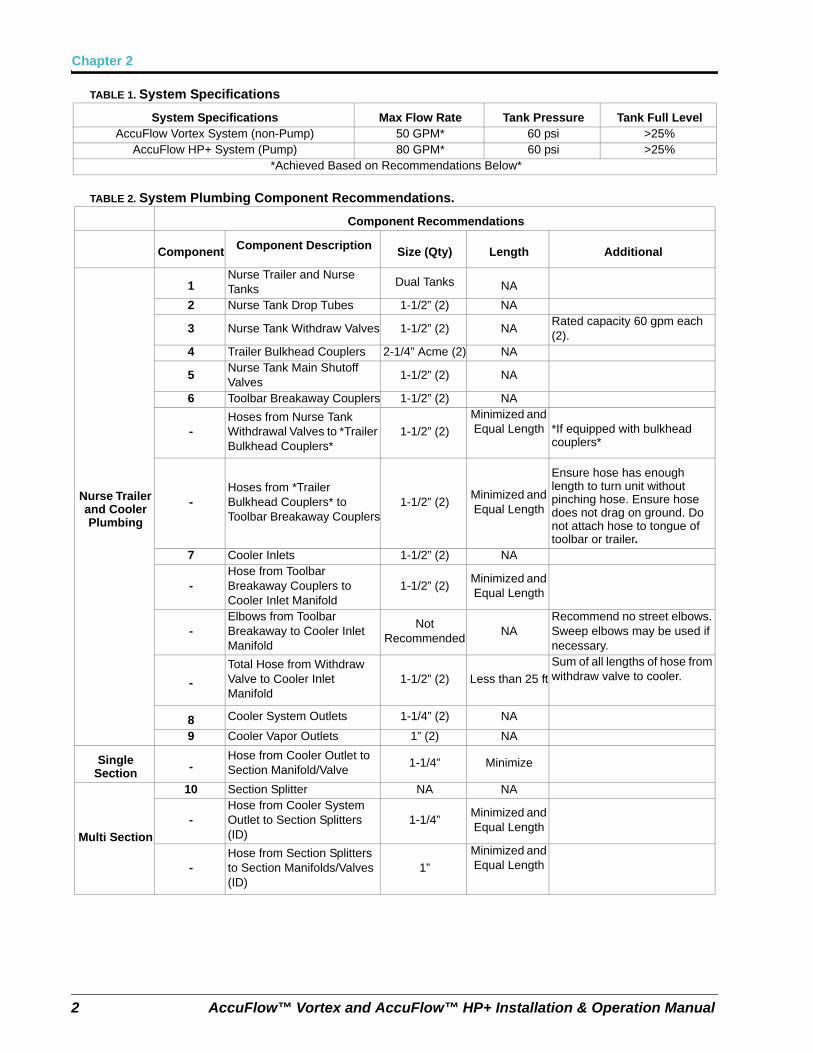
Note: System capacity will vary based upon ambient conditions and plumbing configurations of the overall system. Refer to the following Table 2 on page 2 for recommended best practices to achieve the specifications listed. For additional assistance, contact a local Raven dealer for more information.
Note: Tank levels less than 25% will also reduce capacity.
Chapter 2
2 AccuFlow™ Vortex and AccuFlow™ HP+ Installation & Operation Manual
TABLE 1. System Specifications
TABLE 2. System Plumbing Component Recommendations.
System Specifications Max Flow Rate Tank Pressure Tank Full LevelAccuFlow Vortex System (non-Pump) 50 GPM* 60 psi >25%
AccuFlow HP+ System (Pump) 80 GPM* 60 psi >25%*Achieved Based on Recommendations Below*
Component Recommendations
Component Component Description Size (Qty) Length Additional
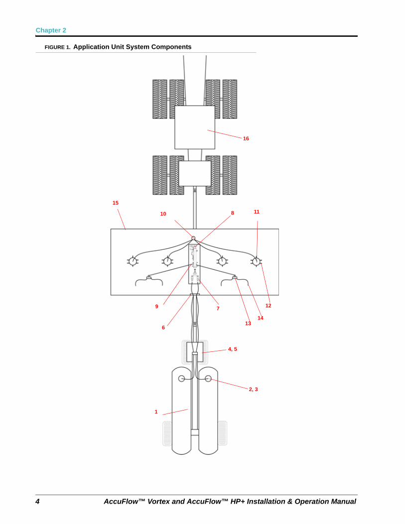
Nurse Trailer and Cooler Plumbing
1Nurse Trailer and Nurse Tanks
Dual Tanks NA
2 Nurse Tank Drop Tubes 1-1/2” (2) NA
3 Nurse Tank Withdraw Valves 1-1/2” (2) NARated capacity 60 gpm each (2).
4 Trailer Bulkhead Couplers 2-1/4” Acme (2) NA
5Nurse Tank Main Shutoff Valves
1-1/2” (2) NA
6 Toolbar Breakaway Couplers 1-1/2” (2) NA
-Hoses from Nurse Tank Withdrawal Valves to *Trailer Bulkhead Couplers*
1-1/2” (2)
Minimized and Equal Length *If equipped with bulkhead
couplers*
-Hoses from *Trailer Bulkhead Couplers* to Toolbar Breakaway Couplers
1-1/2” (2)Minimized and Equal Length
Ensure hose has enough length to turn unit without pinching hose. Ensure hose does not drag on ground. Do not attach hose to tongue of toolbar or trailer.
7 Cooler Inlets 1-1/2” (2) NA
-Hose from Toolbar Breakaway Couplers to Cooler Inlet Manifold
1-1/2” (2)Minimized and Equal Length
-Elbows from Toolbar Breakaway to Cooler Inlet Manifold
Not Recommended
NARecommend no street elbows. Sweep elbows may be used if necessary.
-
Total Hose from Withdraw Valve to Cooler Inlet Manifold
1-1/2” (2) Less than 25 ft
Sum of all lengths of hose from withdraw valve to cooler.
8 Cooler System Outlets 1-1/4” (2) NA
9 Cooler Vapor Outlets 1” (2) NA
Single Section -
Hose from Cooler Outlet to Section Manifold/Valve
1-1/4” Minimize
Multi Section
10 Section Splitter NA NA
-Hose from Cooler System Outlet to Section Splitters (ID)
1-1/4”Minimized and Equal Length
-Hose from Section Splitters to Section Manifolds/Valves (ID)
1”
Minimized and Equal Length
Manual No. 016-0171-573 Rev. B 3
Introduction
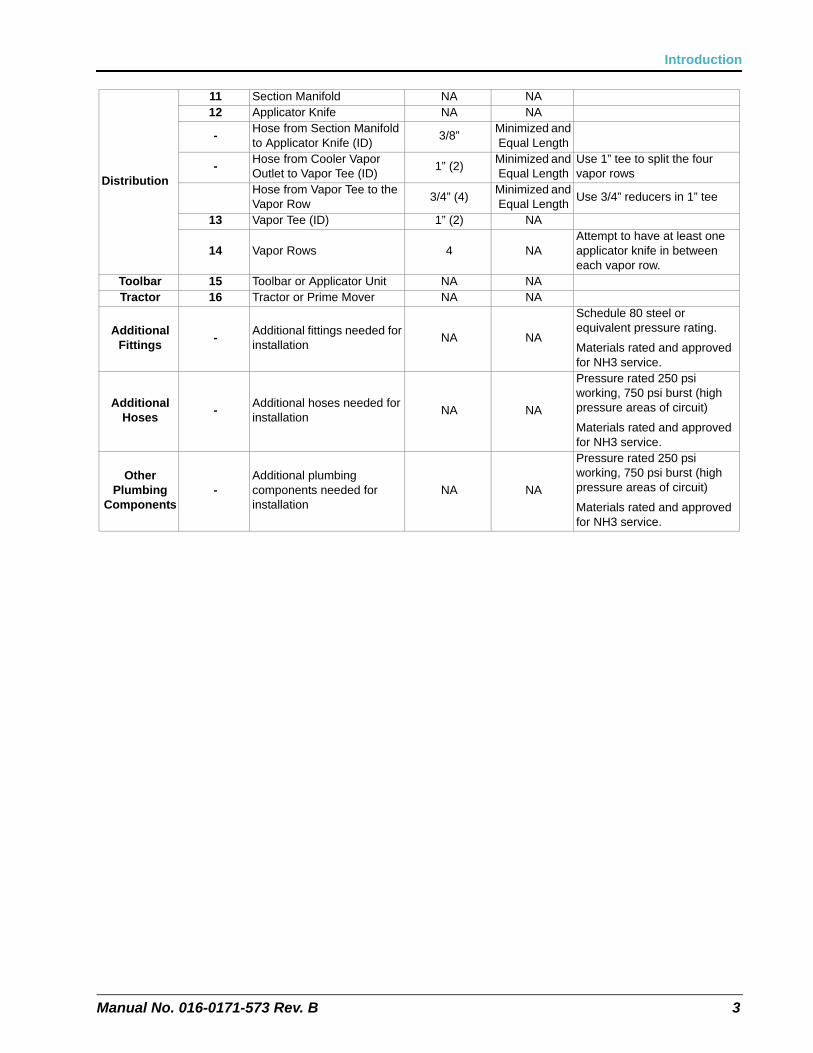
Distribution
11 Section Manifold NA NA12 Applicator Knife NA NA
-Hose from Section Manifold to Applicator Knife (ID)
3/8”Minimized and Equal Length
-Hose from Cooler Vapor Outlet to Vapor Tee (ID)
1” (2)Minimized and Equal Length
Use 1” tee to split the four vapor rows
Hose from Vapor Tee to the Vapor Row
3/4” (4)Minimized and Equal Length
Use 3/4” reducers in 1” tee
13 Vapor Tee (ID) 1” (2) NA
14 Vapor Rows 4 NAAttempt to have at least one applicator knife in between each vapor row.
Toolbar 15 Toolbar or Applicator Unit NA NATractor 16 Tractor or Prime Mover NA NA
Additional Fittings
-Additional fittings needed for installation
NA NA
Schedule 80 steel or equivalent pressure rating.
Materials rated and approved for NH3 service.
Additional Hoses
-Additional hoses needed for installation
NA NA
Pressure rated 250 psi working, 750 psi burst (high pressure areas of circuit)
Materials rated and approved for NH3 service.
Other Plumbing
Components-
Additional plumbing components needed for installation
NA NA
Pressure rated 250 psi working, 750 psi burst (high pressure areas of circuit)
Materials rated and approved for NH3 service.
Chapter 2
4 AccuFlow™ Vortex and AccuFlow™ HP+ Installation & Operation Manual
FIGURE 1. Application Unit System Components
1
2, 3
4, 5
6
7
8
9
10 11
12
1314
16
15

Manual No. 016-0171-573 Rev. B 5
Introduction
UpdatesUpdates for Raven manuals as well as software updates for Raven consoles are available at the Raven Applied Technology Division web site:
www.ravenhelp.com
At Raven Industries, we strive to make your experience with our products as rewarding aspossible. One way to improve this experience is to provide us with feedback on this manual.
Your feedback will help shape the future of our product documentation and the overall servicewe provide. We appreciate the opportunity to see ourselves as our customers see us and areeager to gather ideas on how we have been helping or how we can do better.
To serve you best, please send an email with the following information to
-Accuflow Vortex and Accuflow HP+ Installation & Operation Manual-Manual No. 016-0171-573 Rev. B-Any comments or feedback (include chapter or page numbers if applicable).-Let us know how long have you been using this or other Raven products.
We will not share your email or any information you provide with anyone else. Your feedbackis valued and extremely important to us.
Thank you for your time.

Chapter 2
6 AccuFlow™ Vortex and AccuFlow™ HP+ Installation & Operation Manual
CHAPTER
3
Manual No. 016-0171-573 Rev. B 7
Chapter 3AccuFlow™ Vortex and AccuFlow™ HP+ Installation
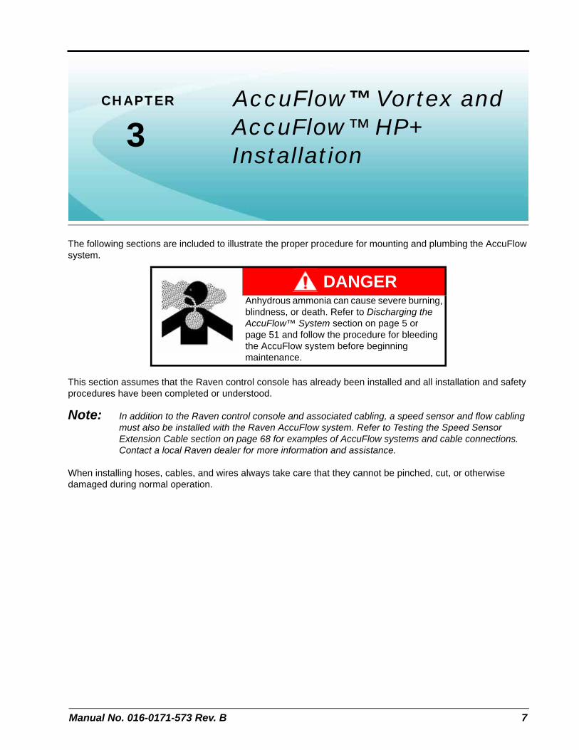
The following sections are included to illustrate the proper procedure for mounting and plumbing the AccuFlow
system.
This section assumes that the Raven control console has already been installed and all installation and safety procedures have been completed or understood.
Note: In addition to the Raven control console and associated cabling, a speed sensor and flow cabling must also be installed with the Raven AccuFlow system. Refer to Testing the Speed Sensor Extension Cable section on page 68 for examples of AccuFlow systems and cable connections. Contact a local Raven dealer for more information and assistance.
When installing hoses, cables, and wires always take care that they cannot be pinched, cut, or otherwise damaged during normal operation.
DANGERAnhydrous ammonia can cause severe burning, blindness, or death. Refer to Discharging the AccuFlow™ System section on page 5 or page 51 and follow the procedure for bleeding the AccuFlow system before beginning maintenance.
Chapter 3
8 AccuFlow™ Vortex and AccuFlow™ HP+ Installation & Operation Manual
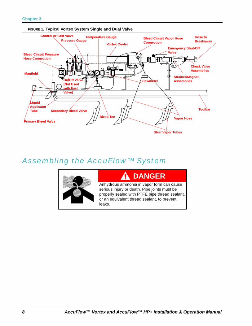
FIGURE 1. Typical Vortex System Single and Dual Valve
Assembling the AccuFlow™ System
DANGERAnhydrous ammonia in vapor form can cause serious injury or death. Pipe joints must be properly sealed with PTFE pipe thread sealant, or an equivalent thread sealant, to prevent leaks.
Primary Bleed Valve
Secondary Bleed Valve
Bleed Tee Vapor Hose
Toolbar
Hose to Breakaway
Bleed Circuit Pressure Hose Connection
Pressure GaugeTemperature Gauge
Vortex Cooler
Bleed Circuit Vapor Hose Connection
Emergency Shut-Off Valve
Manifold
Liquid Applicator Tube
Steel Vapor Tubes
Strainer/Magnet Assemblies
Check Valve Assemblies
Flowmeter
Control or Fast Valve
On/Off Valve (Not Used with Fast Valve)
3
Manual No. 016-0171-573 Rev. B 9
AccuFlow™ Vortex and AccuFlow™ HP+ Installation
Cooler Bracket Assembly
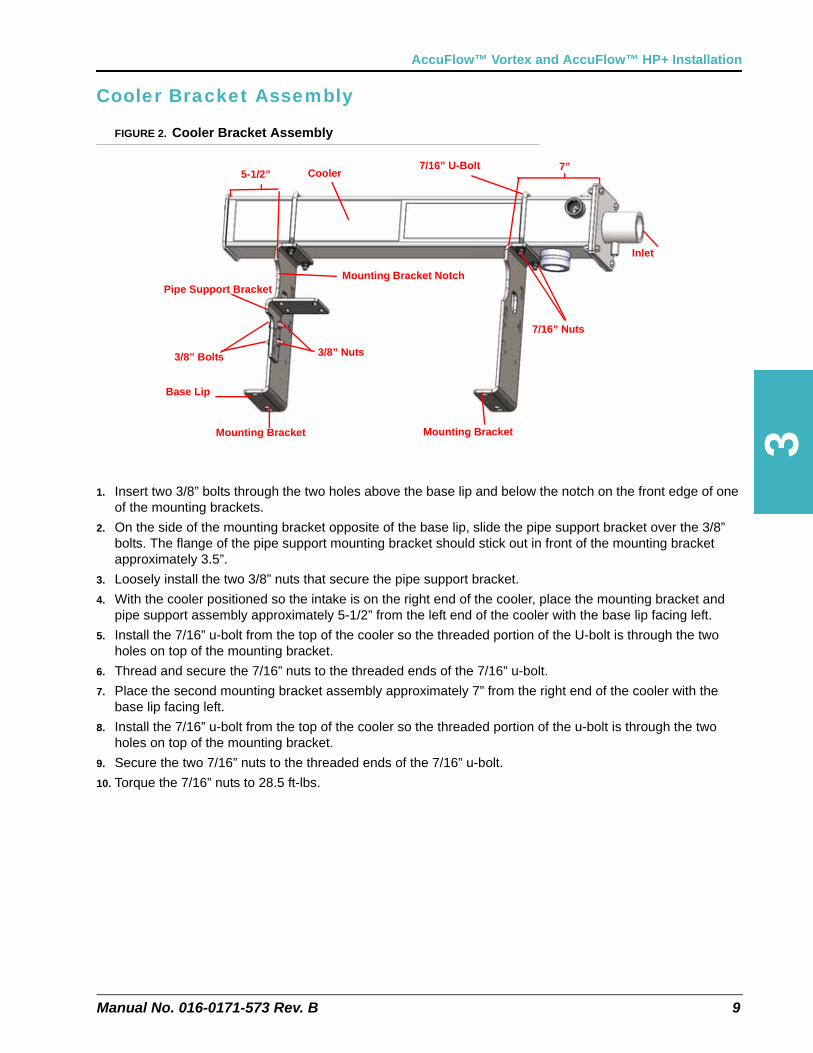
FIGURE 2. Cooler Bracket Assembly
1. Insert two 3/8” bolts through the two holes above the base lip and below the notch on the front edge of one of the mounting brackets.
2. On the side of the mounting bracket opposite of the base lip, slide the pipe support bracket over the 3/8” bolts. The flange of the pipe support mounting bracket should stick out in front of the mounting bracket approximately 3.5”.
3. Loosely install the two 3/8” nuts that secure the pipe support bracket.
4. With the cooler positioned so the intake is on the right end of the cooler, place the mounting bracket and pipe support assembly approximately 5-1/2” from the left end of the cooler with the base lip facing left.
5. Install the 7/16” u-bolt from the top of the cooler so the threaded portion of the U-bolt is through the two holes on top of the mounting bracket.
6. Thread and secure the 7/16” nuts to the threaded ends of the 7/16” u-bolt.
7. Place the second mounting bracket assembly approximately 7” from the right end of the cooler with the base lip facing left.
8. Install the 7/16” u-bolt from the top of the cooler so the threaded portion of the u-bolt is through the two holes on top of the mounting bracket.
9. Secure the two 7/16” nuts to the threaded ends of the 7/16” u-bolt.
10. Torque the 7/16” nuts to 28.5 ft-lbs.
Cooler
Mounting Bracket Mounting Bracket
7/16” U-Bolt
7/16” Nuts
Pipe Support Bracket
3/8” Bolts 3/8” Nuts
Mounting Bracket Notch
Base Lip
5-1/2”7”
Inlet
Chapter 3
10 AccuFlow™ Vortex and AccuFlow™ HP+ Installation & Operation Manual
Flow Meter and Outlet Manifold Assembly
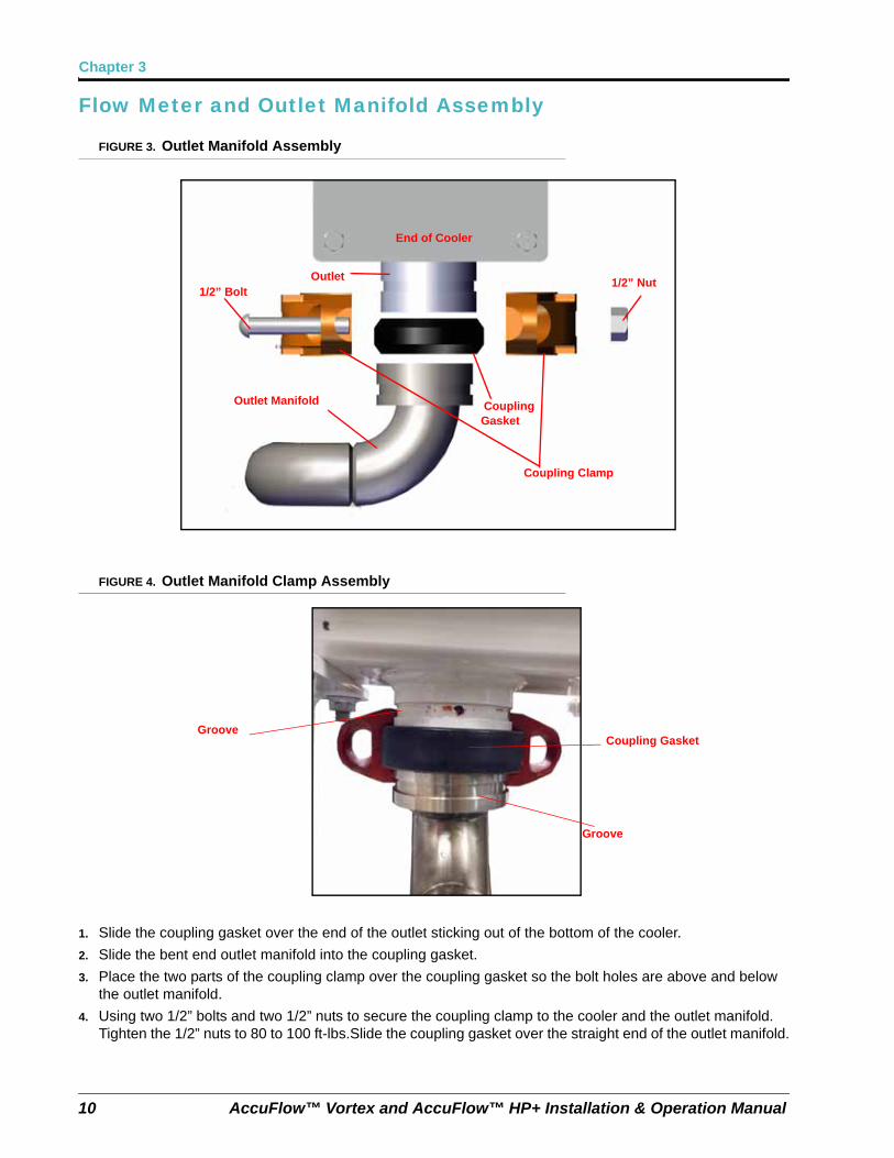
FIGURE 3. Outlet Manifold Assembly
FIGURE 4. Outlet Manifold Clamp Assembly
1. Slide the coupling gasket over the end of the outlet sticking out of the bottom of the cooler.
2. Slide the bent end outlet manifold into the coupling gasket.
3. Place the two parts of the coupling clamp over the coupling gasket so the bolt holes are above and below the outlet manifold.
4. Using two 1/2” bolts and two 1/2” nuts to secure the coupling clamp to the cooler and the outlet manifold. Tighten the 1/2” nuts to 80 to 100 ft-lbs.Slide the coupling gasket over the straight end of the outlet manifold.
1/2” Bolt
Coupling Clamp
1/2” Nut
End of Cooler
Coupling Gasket
Outlet
Outlet Manifold
Coupling GasketGroove
Groove
3
Manual No. 016-0171-573 Rev. B 11
AccuFlow™ Vortex and AccuFlow™ HP+ Installation
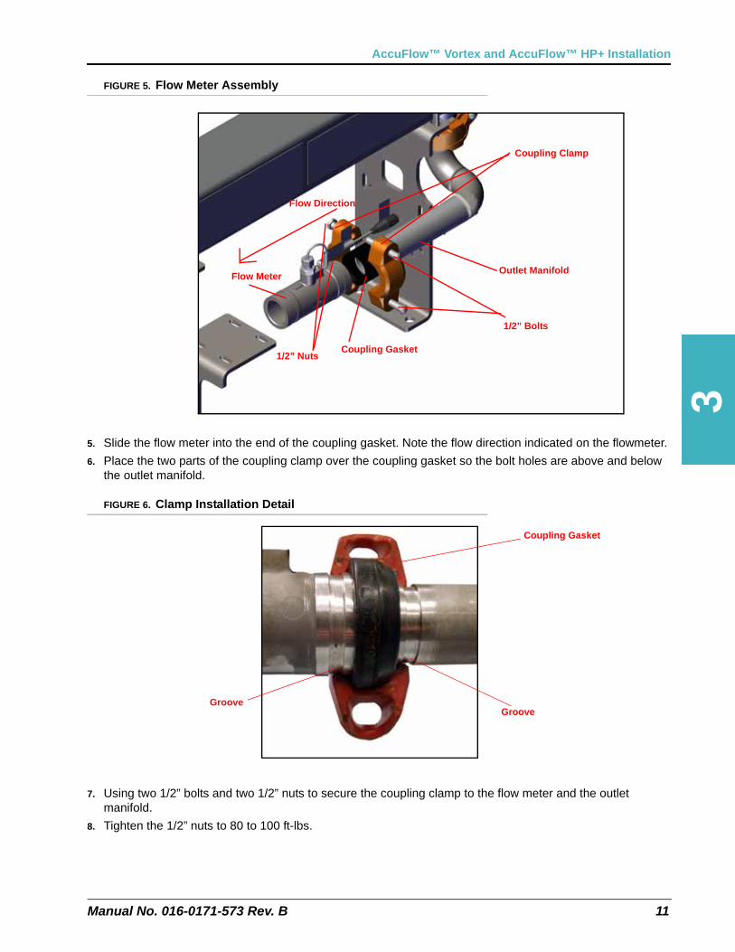
FIGURE 5. Flow Meter Assembly
5. Slide the flow meter into the end of the coupling gasket. Note the flow direction indicated on the flowmeter.
6. Place the two parts of the coupling clamp over the coupling gasket so the bolt holes are above and below the outlet manifold.
FIGURE 6. Clamp Installation Detail
7. Using two 1/2” bolts and two 1/2” nuts to secure the coupling clamp to the flow meter and the outlet manifold.
8. Tighten the 1/2” nuts to 80 to 100 ft-lbs.
1/2” Bolts
Outlet Manifold
Coupling Gasket1/2” Nuts
Coupling Clamp
Flow Meter
Flow Direction
Coupling Gasket
GrooveGroove
Chapter 3
12 AccuFlow™ Vortex and AccuFlow™ HP+ Installation & Operation Manual
Gauge Tree and Valve Assembly
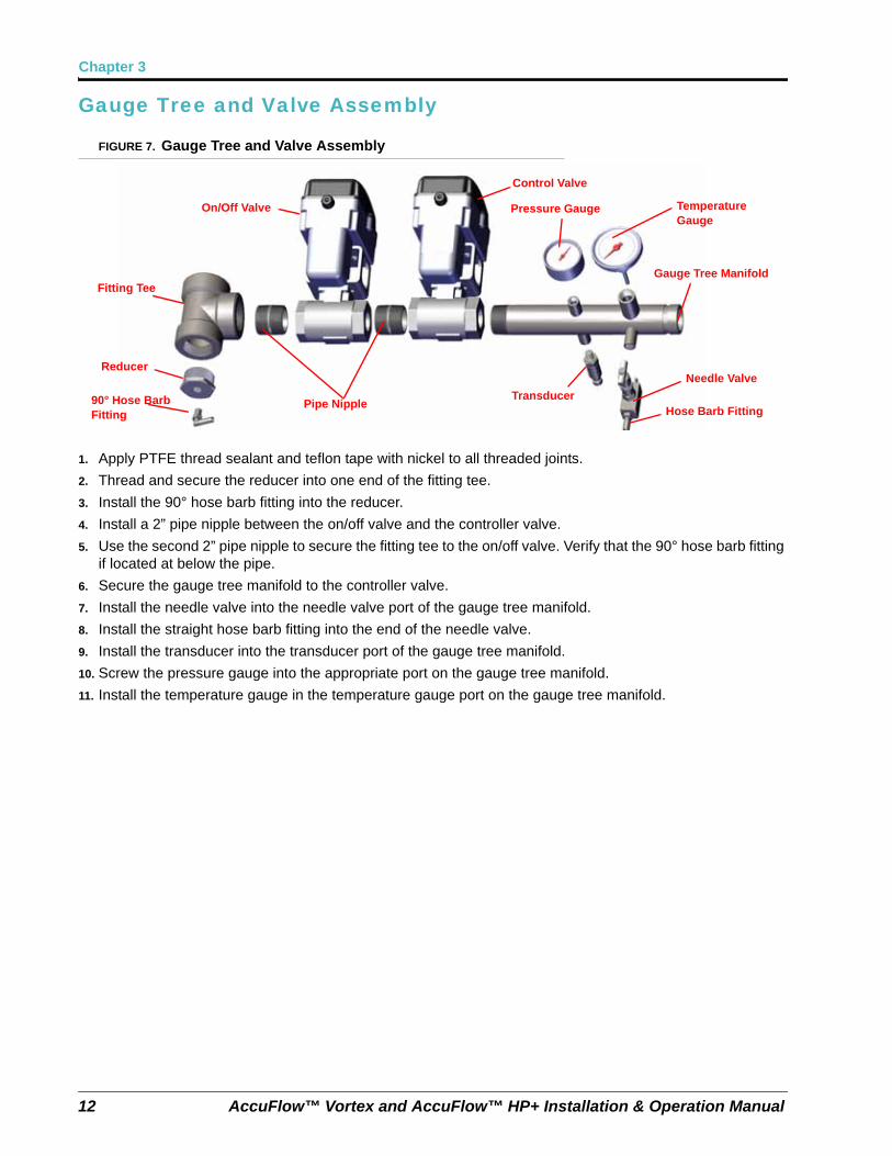
FIGURE 7. Gauge Tree and Valve Assembly
1. Apply PTFE thread sealant and teflon tape with nickel to all threaded joints.
2. Thread and secure the reducer into one end of the fitting tee.
3. Install the 90° hose barb fitting into the reducer.
4. Install a 2” pipe nipple between the on/off valve and the controller valve.
5. Use the second 2” pipe nipple to secure the fitting tee to the on/off valve. Verify that the 90° hose barb fitting if located at below the pipe.
6. Secure the gauge tree manifold to the controller valve.
7. Install the needle valve into the needle valve port of the gauge tree manifold.
8. Install the straight hose barb fitting into the end of the needle valve.
9. Install the transducer into the transducer port of the gauge tree manifold.
10. Screw the pressure gauge into the appropriate port on the gauge tree manifold.
11. Install the temperature gauge in the temperature gauge port on the gauge tree manifold.
90° Hose Barb Fitting
Reducer
Fitting Tee
Pipe Nipple
On/Off Valve
Control Valve
Temperature Gauge
Pressure Gauge
Transducer
Needle Valve
Hose Barb Fitting
Gauge Tree Manifold
Manual No. 016-0171-573 Rev. B 13
AccuFlow™ Vortex and AccuFlow™ HP+ Installation
Attaching the Gauge Tree to the Cooler
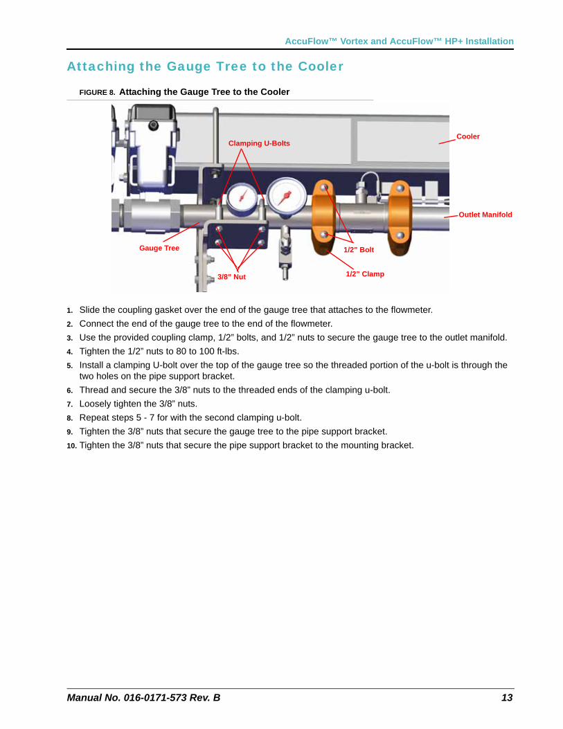
FIGURE 8. Attaching the Gauge Tree to the Cooler
1. Slide the coupling gasket over the end of the gauge tree that attaches to the flowmeter.
2. Connect the end of the gauge tree to the end of the flowmeter.
3. Use the provided coupling clamp, 1/2” bolts, and 1/2” nuts to secure the gauge tree to the outlet manifold.
4. Tighten the 1/2” nuts to 80 to 100 ft-lbs.
5. Install a clamping U-bolt over the top of the gauge tree so the threaded portion of the u-bolt is through the two holes on the pipe support bracket.
6. Thread and secure the 3/8” nuts to the threaded ends of the clamping u-bolt.
7. Loosely tighten the 3/8” nuts.
8. Repeat steps 5 - 7 for with the second clamping u-bolt.
9. Tighten the 3/8” nuts that secure the gauge tree to the pipe support bracket.
10. Tighten the 3/8” nuts that secure the pipe support bracket to the mounting bracket.
Clamping U-Bolts
1/2” Clamp3/8” Nut
1/2” BoltGauge Tree
Outlet Manifold
Cooler
Chapter 3
14 AccuFlow™ Vortex and AccuFlow™ HP+ Installation & Operation Manual
Check Valve Assembly (For Multiple Section Valves Only)
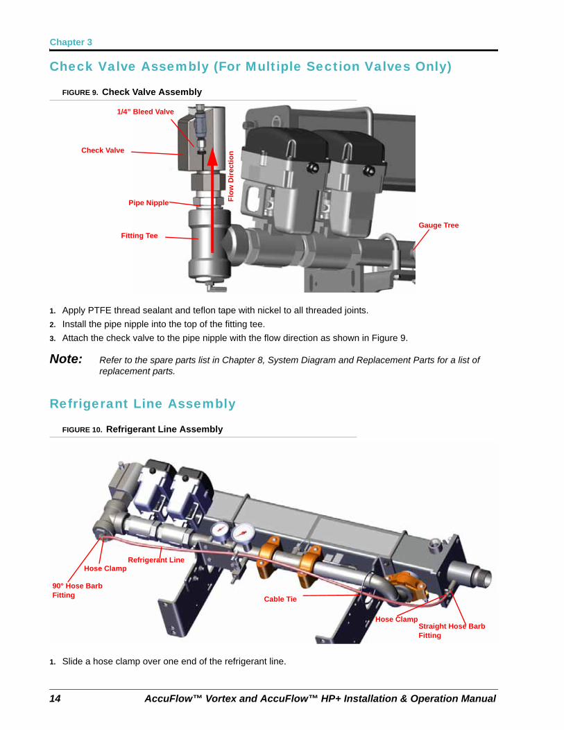
FIGURE 9. Check Valve Assembly
1. Apply PTFE thread sealant and teflon tape with nickel to all threaded joints.
2. Install the pipe nipple into the top of the fitting tee.
3. Attach the check valve to the pipe nipple with the flow direction as shown in Figure 9.
Note: Refer to the spare parts list in Chapter 8, System Diagram and Replacement Parts for a list of replacement parts.
Refrigerant Line Assembly
FIGURE 10. Refrigerant Line Assembly
1. Slide a hose clamp over one end of the refrigerant line.
Pipe Nipple
Check Valve
Fitting Tee
Gauge Tree
1/4” Bleed Valve
Flo
w D
irec
tio
n
90° Hose Barb Fitting
Straight Hose Barb Fitting
Hose Clamp
Hose ClampRefrigerant Line
Cable Tie
Manual No. 016-0171-573 Rev. B 15
AccuFlow™ Vortex and AccuFlow™ HP+ Installation
2. Slide the refrigerant line over the 90° hose barb fitting.
3. Secure the hose clamp over the 90° hose barb fitting.
4. Slide a hose clamp over the other end of the refrigerant line.
5. Slide the refrigerant line over the straight hose barb fitting.
6. Secure the hose clamp over the straight hose barb fitting.
7. Secure the refrigerant line to the outlet manifold with a cable tie.
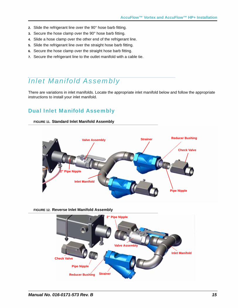
Inlet Manifold AssemblyThere are variations in inlet manifolds. Locate the appropriate inlet manifold below and follow the appropriate instructions to install your inlet manifold.
Dual Inlet Manifold Assembly
FIGURE 11. Standard Inlet Manifold Assembly
FIGURE 12. Reverse Inlet Manifold Assembly
Pipe Nipple
Check Valve
StrainerValve Assembly
Inlet Manifold
2” Pipe Nipple
Reducer Bushing
Pipe Nipple
Check Valve
Strainer
Valve Assembly
Inlet Manifold
2” Pipe Nipple
Reducer Bushing
Chapter 3
16 AccuFlow™ Vortex and AccuFlow™ HP+ Installation & Operation Manual
1. Apply PTFE thread sealant and teflon tape with nickel to all threaded joints.
2. Install the 2” pipe nipple into the end of the cooler.
3. Attach the valve assembly to the end of the valve assembly to the 2” pipe nipple.
4. Secure the inlet manifold to the other end of the valve assembly.
5. Attach a strainer to each end of the inlet manifold. Ensure both strainers are in the same position.
6. Install and tighten a reducer bushing and a pipe nipple into the end of each strainer.
7. Install and tighten a check valve on each pipe nipple.
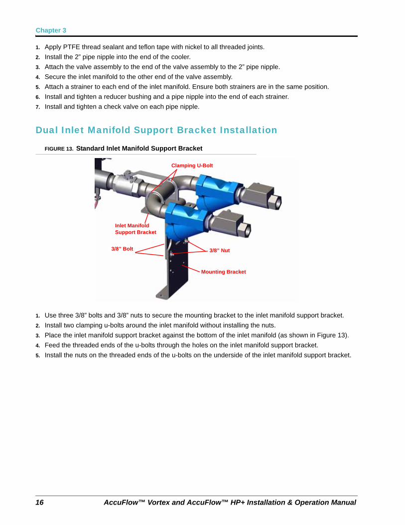
Dual Inlet Manifold Support Bracket Installation
FIGURE 13. Standard Inlet Manifold Support Bracket
1. Use three 3/8” bolts and 3/8” nuts to secure the mounting bracket to the inlet manifold support bracket.
2. Install two clamping u-bolts around the inlet manifold without installing the nuts.
3. Place the inlet manifold support bracket against the bottom of the inlet manifold (as shown in Figure 13).
4. Feed the threaded ends of the u-bolts through the holes on the inlet manifold support bracket.
5. Install the nuts on the threaded ends of the u-bolts on the underside of the inlet manifold support bracket.
Clamping U-Bolt
Inlet Manifold Support Bracket
3/8” Bolt 3/8” Nut
Mounting Bracket
Manual No. 016-0171-573 Rev. B 17
AccuFlow™ Vortex and AccuFlow™ HP+ Installation
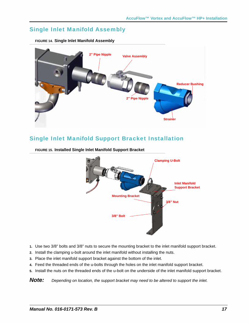
Single Inlet Manifold Assembly
FIGURE 14. Single Inlet Manifold Assembly
Single Inlet Manifold Support Bracket Installation
FIGURE 15. Installed Single Inlet Manifold Support Bracket
1. Use two 3/8” bolts and 3/8” nuts to secure the mounting bracket to the inlet manifold support bracket.
2. Install the clamping u-bolt around the inlet manifold without installing the nuts.
3. Place the inlet manifold support bracket against the bottom of the inlet.
4. Feed the threaded ends of the u-bolts through the holes on the inlet manifold support bracket.
5. Install the nuts on the threaded ends of the u-bolt on the underside of the inlet manifold support bracket.
Note: Depending on location, the support bracket may need to be altered to support the inlet.
2” Pipe Nipple
Strainer
Valve Assembly2” Pipe Nipple
Reducer Bushing
Clamping U-Bolt
Inlet Manifold Support Bracket
3/8” Bolt
3/8” Nut
Mounting Bracket
Chapter 3
18 AccuFlow™ Vortex and AccuFlow™ HP+ Installation & Operation Manual
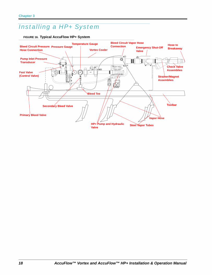
Installing a HP+ SystemFIGURE 16. Typical AccuFlow HP+ System
Primary Bleed Valve
Secondary Bleed Valve
Bleed Tee
Vapor Hose
Toolbar
Hose to Breakaway
Bleed Circuit Pressure Hose Connection
Pressure GaugeTemperature Gauge
Vortex Cooler
Bleed Circuit Vapor Hose Connection Emergency Shut-Off
Valve
HP+ Pump and Hydraulic Valve
Steel Vapor Tubes
Strainer/Magnet Assemblies
Check Valve Assemblies
Fast Valve (Control Valve)
Pump Inlet Pressure Transducer
Manual No. 016-0171-573 Rev. B 19
AccuFlow™ Vortex and AccuFlow™ HP+ Installation
Installing Control Node: AccuFlow HP+
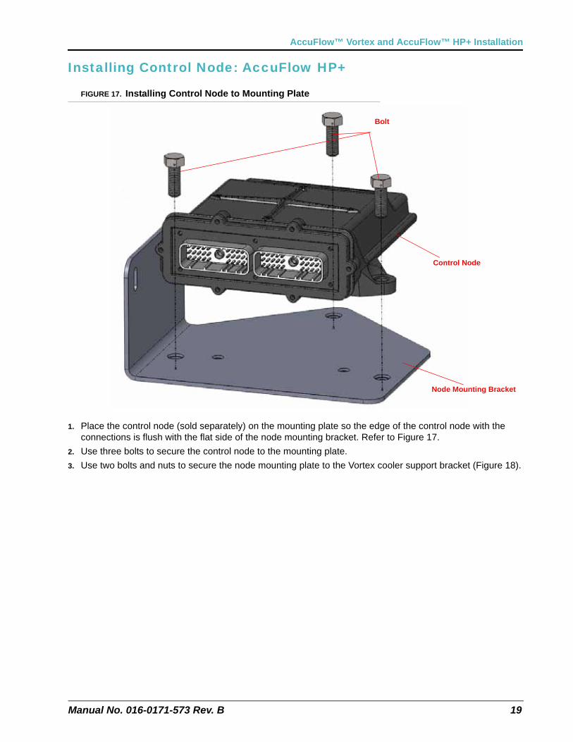
FIGURE 17. Installing Control Node to Mounting Plate
1. Place the control node (sold separately) on the mounting plate so the edge of the control node with the connections is flush with the flat side of the node mounting bracket. Refer to Figure 17.
2. Use three bolts to secure the control node to the mounting plate.
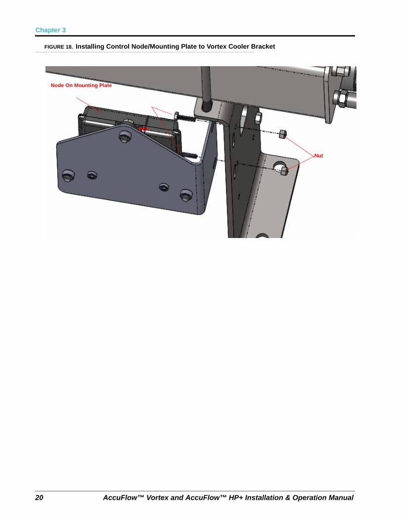
3. Use two bolts and nuts to secure the node mounting plate to the Vortex cooler support bracket (Figure 18).
Bolt
Control Node
Node Mounting Bracket
Chapter 3
20 AccuFlow™ Vortex and AccuFlow™ HP+ Installation & Operation Manual
FIGURE 18. Installing Control Node/Mounting Plate to Vortex Cooler Bracket
Node On Mounting Plate
Bolt
Nut
Manual No. 016-0171-573 Rev. B 21
AccuFlow™ Vortex and AccuFlow™ HP+ Installation
Installing Pump Upgrade (Vortex to HP+ upgrade)
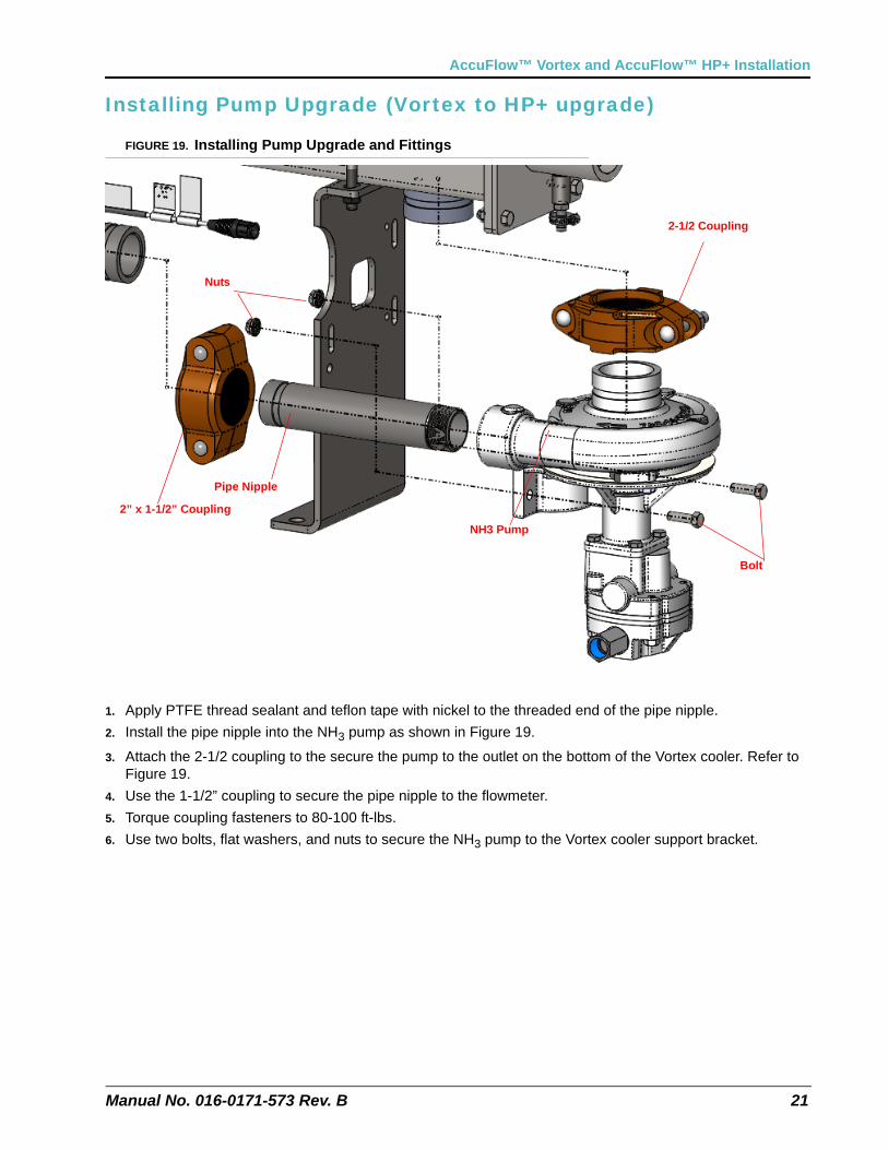
FIGURE 19. Installing Pump Upgrade and Fittings
1. Apply PTFE thread sealant and teflon tape with nickel to the threaded end of the pipe nipple.
2. Install the pipe nipple into the NH3 pump as shown in Figure 19.
3. Attach the 2-1/2 coupling to the secure the pump to the outlet on the bottom of the Vortex cooler. Refer to Figure 19.
4. Use the 1-1/2” coupling to secure the pipe nipple to the flowmeter.
5. Torque coupling fasteners to 80-100 ft-lbs.
6. Use two bolts, flat washers, and nuts to secure the NH3 pump to the Vortex cooler support bracket.
NH3 Pump
Pipe Nipple
2” x 1-1/2” Coupling
2-1/2 Coupling
Bolt
Nuts
Chapter 3
22 AccuFlow™ Vortex and AccuFlow™ HP+ Installation & Operation Manual
Installing Hydraulic Valve
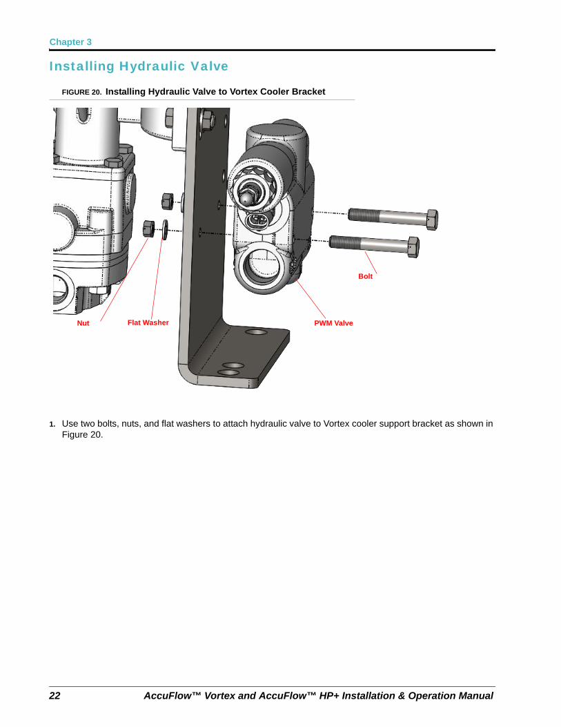
FIGURE 20. Installing Hydraulic Valve to Vortex Cooler Bracket
1. Use two bolts, nuts, and flat washers to attach hydraulic valve to Vortex cooler support bracket as shown in Figure 20.
PWM Valve
Bolt
Nut Flat Washer
Manual No. 016-0171-573 Rev. B 23
AccuFlow™ Vortex and AccuFlow™ HP+ Installation
Boost Pump Hydraulic Connections (HP+ System Only)
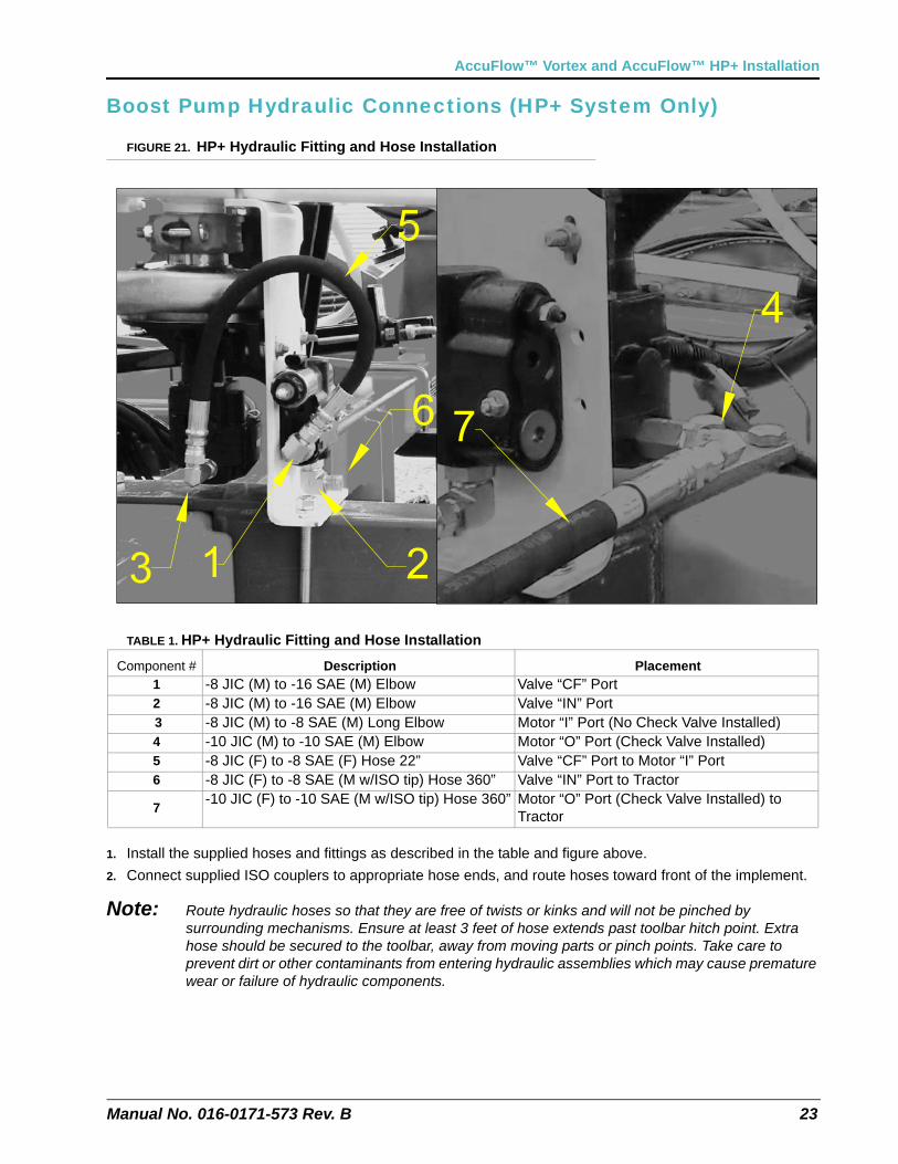
FIGURE 21. HP+ Hydraulic Fitting and Hose Installation
TABLE 1. HP+ Hydraulic Fitting and Hose Installation
1. Install the supplied hoses and fittings as described in the table and figure above.
2. Connect supplied ISO couplers to appropriate hose ends, and route hoses toward front of the implement.
Note: Route hydraulic hoses so that they are free of twists or kinks and will not be pinched by surrounding mechanisms. Ensure at least 3 feet of hose extends past toolbar hitch point. Extra hose should be secured to the toolbar, away from moving parts or pinch points. Take care to prevent dirt or other contaminants from entering hydraulic assemblies which may cause premature wear or failure of hydraulic components.
Component # Description Placement1 -8 JIC (M) to -16 SAE (M) Elbow Valve “CF” Port2 -8 JIC (M) to -16 SAE (M) Elbow Valve “IN” Port 3 -8 JIC (M) to -8 SAE (M) Long Elbow Motor “I” Port (No Check Valve Installed)4 -10 JIC (M) to -10 SAE (M) Elbow Motor “O” Port (Check Valve Installed)5 -8 JIC (F) to -8 SAE (F) Hose 22” Valve “CF” Port to Motor “I” Port6 -8 JIC (F) to -8 SAE (M w/ISO tip) Hose 360” Valve “IN” Port to Tractor
7-10 JIC (F) to -10 SAE (M w/ISO tip) Hose 360” Motor “O” Port (Check Valve Installed) to
Tractor
Chapter 3
24 AccuFlow™ Vortex and AccuFlow™ HP+ Installation & Operation Manual
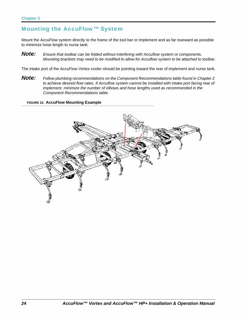
Mounting the AccuFlow™ System
Mount the AccuFlow system directly to the frame of the tool bar or implement and as far rearward as possible to minimize hose length to nurse tank.
Note: Ensure that toolbar can be folded without interfering with Accuflow system or components. Mounting brackets may need to be modified to allow for Accuflow system to be attached to toolbar.
The intake port of the AccuFlow Vortex cooler should be pointing toward the rear of implement and nurse tank.
Note: Follow plumbing recommendations on the Component Recommendations table found in Chapter 2 to achieve desired flow rates. If Accuflow system cannot be installed with intake port facing rear of implement, minimize the number of elbows and hose lengths used as recommended in the Component Recommendations table.
FIGURE 22. AccuFlow Mounting Example
Manual No. 016-0171-573 Rev. B 25
AccuFlow™ Vortex and AccuFlow™ HP+ Installation
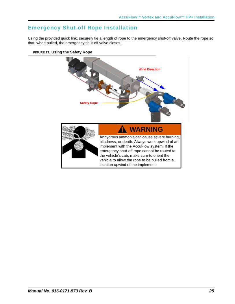
Emergency Shut-off Rope Installation
Using the provided quick link, securely tie a length of rope to the emergency shut-off valve. Route the rope so that, when pulled, the emergency shut-off valve closes.
FIGURE 23. Using the Safety Rope
WARNINGAnhydrous ammonia can cause severe burning, blindness, or death. Always work upwind of an implement with the AccuFlow system. If the emergency shut-off rope cannot be routed to the vehicle’s cab, make sure to orient the vehicle to allow the rope to be pulled from a location upwind of the implement.
Safety Rope
Wind Direction
Chapter 3
26 AccuFlow™ Vortex and AccuFlow™ HP+ Installation & Operation Manual
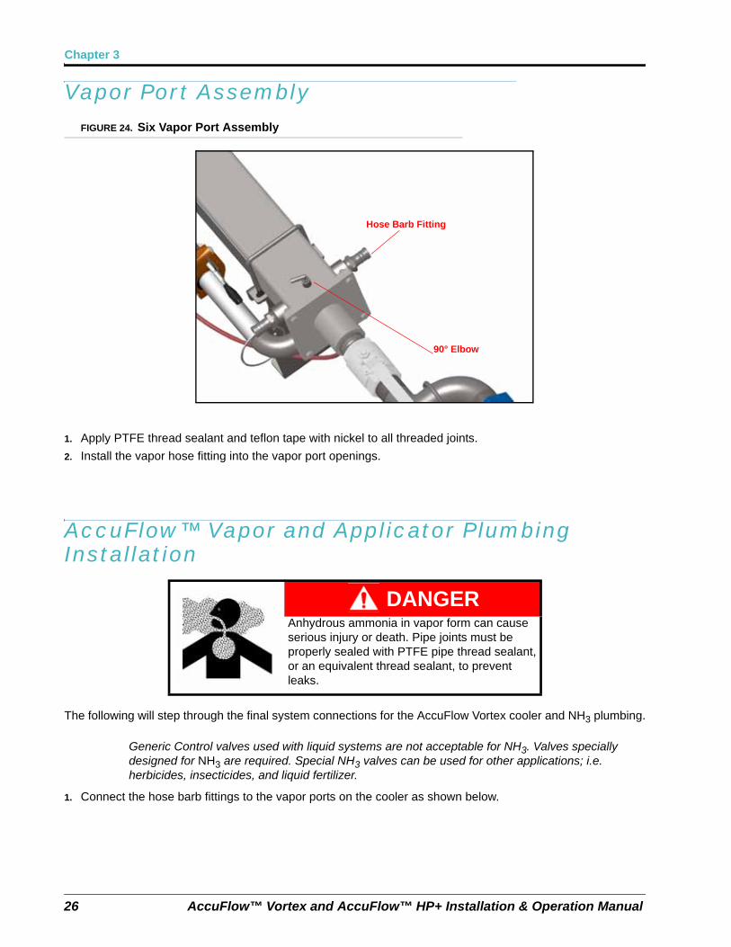
Vapor Port AssemblyFIGURE 24. Six Vapor Port Assembly
1. Apply PTFE thread sealant and teflon tape with nickel to all threaded joints.
2. Install the vapor hose fitting into the vapor port openings.
AccuFlow™ Vapor and Applicator Plumbing Installation
The following will step through the final system connections for the AccuFlow Vortex cooler and NH3 plumbing.
Generic Control valves used with liquid systems are not acceptable for NH3. Valves specially designed for NH3 are required. Special NH3 valves can be used for other applications; i.e. herbicides, insecticides, and liquid fertilizer.
1. Connect the hose barb fittings to the vapor ports on the cooler as shown below.
DANGERAnhydrous ammonia in vapor form can cause serious injury or death. Pipe joints must be properly sealed with PTFE pipe thread sealant, or an equivalent thread sealant, to prevent leaks.
Hose Barb Fitting
90° Elbow
Manual No. 016-0171-573 Rev. B 27
AccuFlow™ Vortex and AccuFlow™ HP+ Installation
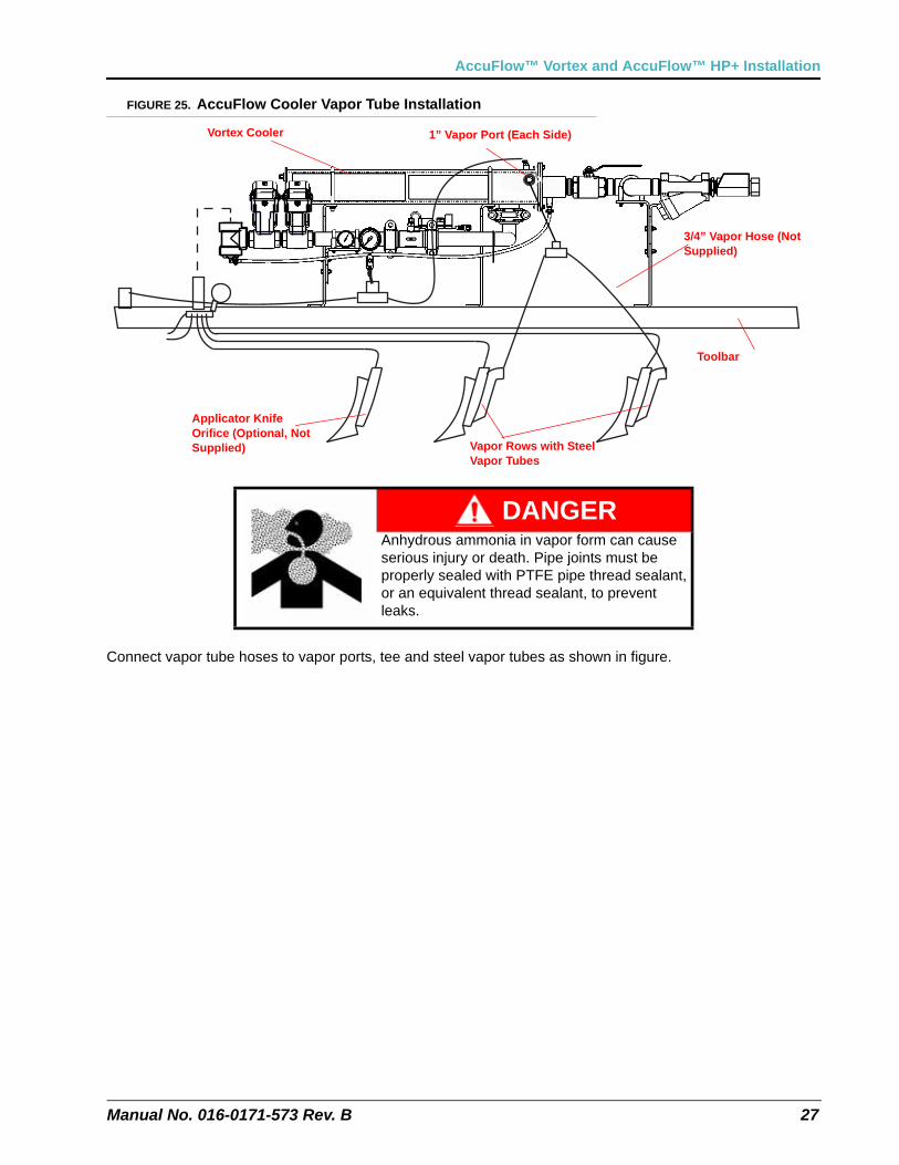
FIGURE 25. AccuFlow Cooler Vapor Tube Installation
Connect vapor tube hoses to vapor ports, tee and steel vapor tubes as shown in figure.
DANGERAnhydrous ammonia in vapor form can cause serious injury or death. Pipe joints must be properly sealed with PTFE pipe thread sealant, or an equivalent thread sealant, to prevent leaks.
Vortex Cooler 1” Vapor Port (Each Side)
3/4” Vapor Hose (Not Supplied)
Vapor Rows with Steel Vapor Tubes
Applicator Knife Orifice (Optional, Not Supplied)
Toolbar
Chapter 3
28 AccuFlow™ Vortex and AccuFlow™ HP+ Installation & Operation Manual
2. Weld vapor tubes provided with the kit to the back of liquid tubes. Vapor tubes should be spaced out evenly across the tool bar. Avoid connecting vapor tubes on wheel tracks and adjacent rows if possible.
3. Route 3/4” tubing from the 3/4” cooler vapor ports to the vapor tube tee as shown in figure. Cut tube lengths in equal lengths and allow enough hose to avoid kinking at any folding points. Connect one end of the vapor line to the hose barb on the cooler and secure using a supplied hose clamp. Connect the other end to the vapor tubes installed on the implement and secure using the supplied hose clamps.
Note: Consult a local NH3 supplier for appropriate hoses, breakaway fittings, manifolds, and orifices for use with the AccuFlow system. Always install breakaway fittings in the nurse tank supply lines to reduce NH3 discharge if the nurse tank accidentally disconnects from the implement.
Note: To reduce risk of uneven application, Raven recommends using equal length hose to all 4 vapor knives, placed at least 1 row apart.
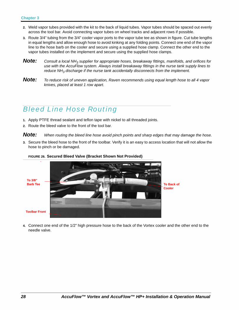
Bleed Line Hose Routing1. Apply PTFE thread sealant and teflon tape with nickel to all threaded joints.
2. Route the bleed valve to the front of the tool bar.
Note: When routing the bleed line hose avoid pinch points and sharp edges that may damage the hose.
3. Secure the bleed hose to the front of the toolbar. Verify it is an easy to access location that will not allow the hose to pinch or be damaged.
FIGURE 26. Secured Bleed Valve (Bracket Shown Not Provided)
4. Connect one end of the 1/2” high pressure hose to the back of the Vortex cooler and the other end to the needle valve.
To 3/8” Barb Tee To Back of
Cooler
Toolbar Front
Manual No. 016-0171-573 Rev. B 29
AccuFlow™ Vortex and AccuFlow™ HP+ Installation
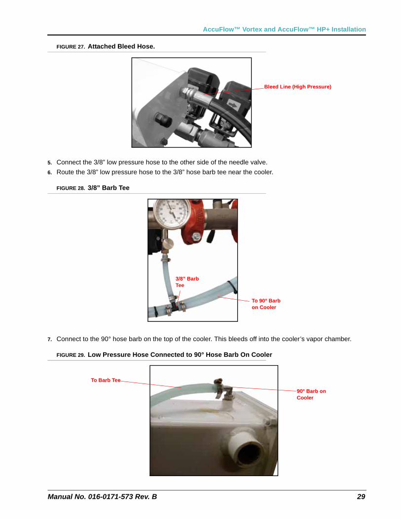
FIGURE 27. Attached Bleed Hose.
5. Connect the 3/8” low pressure hose to the other side of the needle valve.
6. Route the 3/8” low pressure hose to the 3/8” hose barb tee near the cooler.
FIGURE 28. 3/8” Barb Tee
7. Connect to the 90° hose barb on the top of the cooler. This bleeds off into the cooler’s vapor chamber.
FIGURE 29. Low Pressure Hose Connected to 90° Hose Barb On Cooler
Bleed Line (High Pressure)
3/8” Barb Tee
To 90° Barb on Cooler
To Barb Tee
90° Barb on Cooler
Chapter 3
30 AccuFlow™ Vortex and AccuFlow™ HP+ Installation & Operation Manual
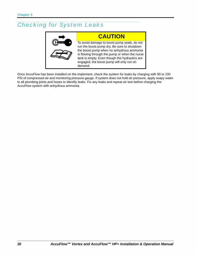
Checking for System Leaks
Once AccuFlow has been installed on the implement, check the system for leaks by charging with 90 to 100 PSI of compressed air and monitoring pressure gauge. If system does not hold air pressure, apply soapy water to all plumbing joints and hoses to identify leaks. Fix any leaks and repeat air test before charging the AccuFlow system with anhydrous ammonia.
CAUTIONTo avoid damage to boost pump seals, do not run the boost pump dry. Be sure to shutdown the boost pump when no anhydrous ammonia is flowing through the pump or when the nurse tank is empty. Even though the hydraulics are engaged, the boost pump will only run on demand.
CHAPTER
4
Manual No. 016-0171-573 Rev. B 31
Chapter 4AccuFlow™ Vortex System (Non-Pump) Calibration and Operation
This chapter contains information on calculating or adjusting calibration values for the AccuFlow system. These values must be programmed on the console providing product control. Refer to the control console Installation and Operation manual for detailed programming instructions.
Note: Before the AccuFlow system and connected console may be used to control anhydrous ammonia application, the following calibration values must be programmed on the Raven product control console:
• Boom Cal
• Speed Cal
• Meter Cal
• Valve Cal
• Rate Cal
Programming NH3 Rate Control
Entering Boom Cal
The boom cal for the AccuFlow system can be calculated with the following formula:
Number of Applicator Knives x Spacing in inches = Implement Width (EQ 1)
For Example:
If the implement has 16 knives spaced 30 inches apart, the calculated implement width is equal to 480 inches. Enter 480 as the boom cal on the control console. If a multi-section implement has 24 knives on 30” spacing and is divided into 3 equal sections, the calculated section width is 8 knives x 30” = 240”. Enter 240 as the boom cal for section 1, section 2 & section 3.
Entering Speed Cal
Calculate and enter the speed cal according to the console’s Installation and Operation manual. No adjustments to the speed cal are required for the AccuFlow system.
Chapter 4
32 AccuFlow™ Vortex and AccuFlow™ HP+ Installation & Operation Manual
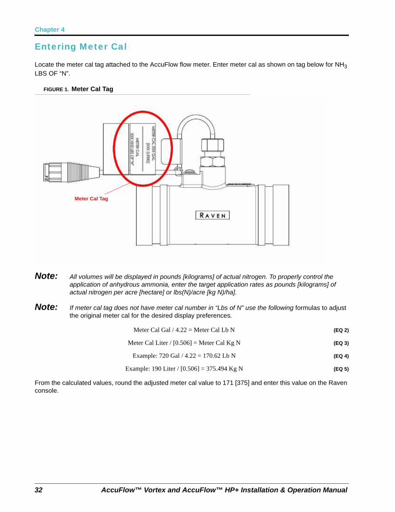
Entering Meter Cal
Locate the meter cal tag attached to the AccuFlow flow meter. Enter meter cal as shown on tag below for NH3 LBS OF “N”.
FIGURE 1. Meter Cal Tag
Note: All volumes will be displayed in pounds [kilograms] of actual nitrogen. To properly control the application of anhydrous ammonia, enter the target application rates as pounds [kilograms] of actual nitrogen per acre [hectare] or lbs(N)/acre [kg N)/ha].
Note: If meter cal tag does not have meter cal number in “Lbs of N” use the following formulas to adjust the original meter cal for the desired display preferences.
Meter Cal Gal / 4.22 = Meter Cal Lb N (EQ 2)
Meter Cal Liter / [0.506] = Meter Cal Kg N (EQ 3)
Example: 720 Gal / 4.22 = 170.62 Lb N (EQ 4)
Example: 190 Liter / [0.506] = 375.494 Kg N (EQ 5)
From the calculated values, round the adjusted meter cal value to 171 [375] and enter this value on the Raven console.
Meter Cal Tag
4
Manual No. 016-0171-573 Rev. B 33
AccuFlow™ Vortex System (Non-Pump) Calibration and Operation
Adjusting Valve Cal
Refer to the console Installation and Operation Manual for instructions on entering or adjusting the valve cal.
Note: The valve cal may need to be adjusted to speed up or slow down the valve to obtain desired results, particularly in applications using low flow rates.
Recommended Starting Valve Cals:
Vortex Fast Valve: 743 (If too slow try 643 or 543)
Vortex Two Valve: 2123 (If too slow try 2223 or 2323. If low-rate control is unstable, try 2133 or 2143)
Adjusting Rate Cal
Enter the target rate in actual pounds of nitrogen (N) per acre [kilograms per hectare].
Calculating the Required Capacity
To ensure that the desired application rate (in pounds [kilograms] of actual nitrogen per minute) does not exceed the AccuFlow system capacity, the required capacity of the application must be verified.
Using the following formula to calculate the required capacity:
Target Application Rate x Target Application Speed x Implement Width = lbs[kg](N)/min5940[60,000] (EQ 6)
Note: Be sure to enter the target application rate in pounds [kilograms] of nitrogen per acre [hectare] and the implement width as calculated in the “Entering Boom Cal” section on page 31.
For Example:(English Units) Given a target application rate of 150 lbs(N)/acre at an average of 5.5 mph and a calculated implement width of 480 inches, the required capacity is:
150 x 5.5 x 480 = 66.6 lbs(N)/min5940.......................... (EQ 7)
(SI Units) Given a target application rate of 68 kg(N)/ha at an average of 10 km/hr and a calculated implement width of 1220 centimeters, the required capacity is:
68 x 10 x 1220 = 13.8 kg(N)/min60,000........................ (EQ 8)
The maximum capacities of the various AccuFlow systems are shown below: Contact a local Raven dealer if the maximum rate is exceeded.
a. Single tank Vortex: 126 lbN/min [57 kgN/min].
b. Dual tank/dual hose Vortex: 210 lbN/min [95 kgN/min].
Chapter 4
34 AccuFlow™ Vortex and AccuFlow™ HP+ Installation & Operation Manual
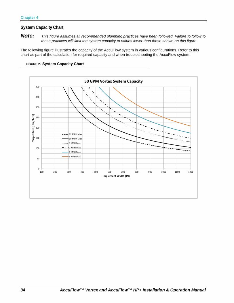
System Capacity Chart
Note: This figure assumes all recommended plumbing practices have been followed. Failure to follow to those practices will limit the system capacity to values lower than those shown on this figure.
The following figure illustrates the capacity of the AccuFlow system in various configurations. Refer to this chart as part of the calculation for required capacity and when troubleshooting the AccuFlow system.
FIGURE 2. System Capacity Chart
0
50
100
150
200
250
300
350
400
100 200 300 400 500 600 700 800 900 1000 1100 1200
Target
Rate
(LbN
/Acre)
Implement Width (IN)
50 GPM Vortex System Capacity
12 MPH Max
10 MPH Max
8 MPH Max
7 MPH Max
6 MPH Max
5 MPH Max
4
Manual No. 016-0171-573 Rev. B 35
AccuFlow™ Vortex System (Non-Pump) Calibration and Operation
AccuFlow NH3 Orifice Kit Instructions
Overview
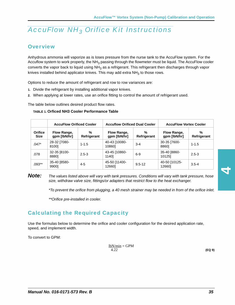
Anhydrous ammonia will vaporize as is loses pressure from the nurse tank to the AccuFlow system. For the Accuflow system to work properly, the NH3 passing through the flowmeter must be liquid. The AccuFlow cooler converts the vapor back to liquid using NH3 as a refrigerant. This refrigerant then discharges through vapor knives installed behind applicator knives. This may add extra NH3 to those rows.
Options to reduce the amount of refrigerant and row to row variances are:
1. Divide the refrigerant by installing additional vapor knives.
2. When applying at lower rates, use an orifice fitting to control the amount of refrigerant used.
The table below outlines desired product flow rates.
TABLE 1. Orficed NH3 Cooler Performance Table
Note: The values listed above will vary with tank pressures. Conditions will vary with tank pressure, hose size, withdraw valve size, fittings/or adapters that restrict flow to the heat exchanger.
*To prevent the orifice from plugging, a 40 mesh strainer may be needed in from of the orifice inlet.
**Orifice pre-installed in cooler.
Calculating the Required Capacity
Use the formulas below to determine the orifice and cooler configuration for the desired application rate, speed, and implement width.
To convert to GPM:
lbN/min = GPM 4.22......................... (EQ 9)
AccuFlow Orificed Cooler Accuflow Orificed Dual Cooler AccuFlow Vortex Cooler
Orifice Size
Flow Range, gpm [lbN/hr]
% Refrigerant
Flow Range, gpm [lbN/hr]
% Refrigerant
Flow Range, gpm [lbN/hr]
% Refrigerant
.047*28-32 [7080-8100]
1-1.540-43 [10080-10860]
3-430-35 [7600-8860]
1-1.5
.07832-35 [8100-8880]
2.5-343-45 [10860-1140]
6-935-40 [8860-10125]
2.5-3
.093**35-40 [8580-9900]
4-545-50 [11400-12660]
9.5-1240-50 [10125-12660]
3.5-4
Chapter 4
36 AccuFlow™ Vortex and AccuFlow™ HP+ Installation & Operation Manual
Target Rate (lbN per acre) x Speed (mph) x Implement Width (inches) = lbN/min5940.......................... (EQ 10)
To convert lbN/Hr:
lbN = lbN/min min x 60.......................... (EQ 11)
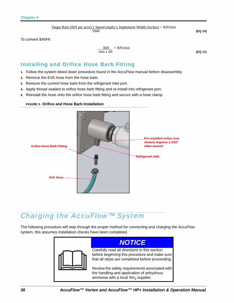
Installing and Orifice Hose Barb Fitting1. Follow the system bleed down procedure found in the AccuFlow manual before disassembly.
2. Remove the EVA hose from the hose barb.
3. Remove the current hose barb from the refrigerant inlet port.
4. Apply thread sealant to orifice hose barb fitting and re-install into refrigerant port.
5. Reinstall the hose onto the orifice hose barb fitting and secure with a hose clamp.
FIGURE 3. Orifice and Hose Barb Installation
Charging the AccuFlow™ SystemThe following procedure will step through the proper method for connecting and charging the AccuFlow system, this assumes installation checks have been completed.
NOTICECarefully read all directions in this section before beginning this procedure and make sure that all steps are completed before proceeding.
Review the safety requirements associated with the handling and application of anhydrous ammonia with a local NH3 supplier.
Orifice Hose Barb Fitting
EVA Hose
Pre-installed orifice (not shown) requires a 3/16” Allen wrench
Refrigerant Inlet
Manual No. 016-0171-573 Rev. B 37
AccuFlow™ Vortex System (Non-Pump) Calibration and Operation
1. Verify that all hoses, fittings, and mounting bolts are securely fastened or tightened.
2. Toggle the master switch to the off position.
3. Close bleed valves and all bleed ports.
4. Verify that the AccuFlow flow meter is connected to the flow meter connector on the product cable.
5. Verify that the AccuFlow control valve is connected to the product cable connector.
6. Verify the on/off valve(s) are connected to the on/off connectors on the product cable.
7. Verify that all motorized valves are in the ‘off’ position.
8. Turn the AccuFlow emergency shut-off valve(s) to the full open position.
9. Connect and secure the hose from the AccuFlow implement to the nurse tank.
10. Slightly open the nurse tank shut-off valve to allow NH3 to slowly pressurize the system.
Note: Opening the emergency shutoff valve or the nurse tank shutoff valves too quickly may result in the excess flow valves on the nurse tanks to close, and the system not to charge properly. Excess flow valves must be re-set before system can be charged.
11. Inspect the system for leaks.
a. If leaks are detected, close the nurse tank shutoff valve and proceed to step 12.
b. If no leaks are detected, skip to step 13.
12. If leaks are present:
a. Close the nurse tank shut-off valve.
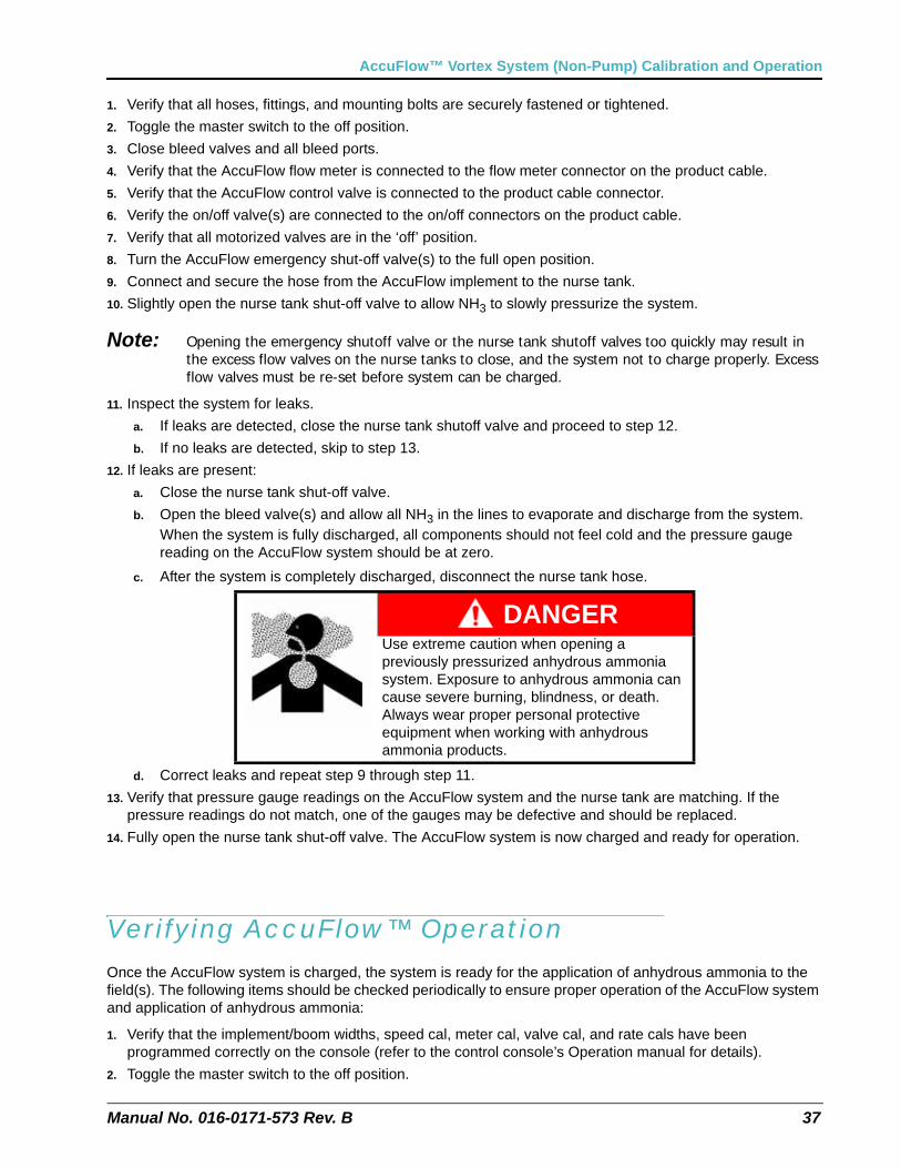
b. Open the bleed valve(s) and allow all NH3 in the lines to evaporate and discharge from the system. When the system is fully discharged, all components should not feel cold and the pressure gauge reading on the AccuFlow system should be at zero.
c. After the system is completely discharged, disconnect the nurse tank hose.
d. Correct leaks and repeat step 9 through step 11.
13. Verify that pressure gauge readings on the AccuFlow system and the nurse tank are matching. If the pressure readings do not match, one of the gauges may be defective and should be replaced.
14. Fully open the nurse tank shut-off valve. The AccuFlow system is now charged and ready for operation.
Verifying AccuFlow™ OperationOnce the AccuFlow system is charged, the system is ready for the application of anhydrous ammonia to the field(s). The following items should be checked periodically to ensure proper operation of the AccuFlow system and application of anhydrous ammonia:
1. Verify that the implement/boom widths, speed cal, meter cal, valve cal, and rate cals have been programmed correctly on the console (refer to the control console’s Operation manual for details).
2. Toggle the master switch to the off position.
DANGERUse extreme caution when opening a previously pressurized anhydrous ammonia system. Exposure to anhydrous ammonia can cause severe burning, blindness, or death. Always wear proper personal protective equipment when working with anhydrous ammonia products.
Chapter 4
38 AccuFlow™ Vortex and AccuFlow™ HP+ Installation & Operation Manual
3. Toggle the console to manual control mode.
4. Toggle the switch for section 1 (boom 1) on. If a multi-manifold system is in use, toggle all sections on. Toggle any section switches not in use to their off positions.
5. With the master switch in the off position, drive at the target application speed to verify the speed readout on the console.
6. With applicator knives in the ground, toggle the master switch to the on position.
7. While driving at the target application speed, manually adjust the flow with the INC/DEC switch until the target rate is achieved.
8. Toggle the console to automatic mode. In automatic mode, the console will adjust the control valve automatically to maintain the target rate regardless of vehicle speed. If the console is not capable of maintaining the target rate, refer Chapter 7, Troubleshooting.
For Example:Given an observed pressure reading 70 PSI and temperature reading 40° F. The point where these two readings intersect is within the non-vapor area. See Figure 1, “Pressure vs. Temperature Chart,” on page 67.
If an additive such as N-Serve (Dow Chemical) or another nitrogen stabilizer is used with the system, periodic cleaning of the AccuFlow flow meter may be required. Refer to Chapter 7, Troubleshooting, for instructions on performing maintenance on the AccuFlow cooler or flow meter.
Note: Due to the highly corrosive nature of many additives and nitrogen stabilizers, Raven recommends injection of the additive after the Vortex cooler, control valve, and vapor lines. This will help prevent corrosion of heat exchangers and other plumbing components. Corroded materials can cause system components such as strainers, flowmeters, and orifices to become obstructed, and can decrease service interval time and component life expectancy.
CHAPTER
5
Manual No. 016-0171-573 Rev. B 39
Chapter 5AccuFlow™ HP+ Calibration and Operation
This chapter contains information on calculating or adjusting calibration values for the AccuFlow HP+ system. These values must be programmed on the console providing product control. Refer to the console Installation and Operation manual for detailed programming instructions.
The HP+ system requires a CANbus system with a Raven product control node.
• The HP+ system uses a 2-stage control. Stage 1 opens the control valve as needed to achieve target rate. Once the valve reaches the full open position, stage 2 starts controlling the pump and ramps it to reach the target rate (assuming tractor hydraulics are on). The process is reversed as the flow demand decreases.
CAUTIONTo avoid damage to boost pump seals, do not run the boost pump dry. Be sure to shutdown the boost pump when no anhydrous ammonia is flowing through the pump or when the nurse tank is empty.
Chapter 5
40 AccuFlow™ Vortex and AccuFlow™ HP+ Installation & Operation Manual
Charging the AccuFlow™ HP+ System and Calibrating the Pressure Transducers (Pressure Cal)The following procedure will step through the proper method for connecting and charging the AccuFlow system.
1. Verify that all hoses, fittings, and mounting bolts are securely fastened or tightened.
2. Verify that the AccuFlow flow meter is connected to the flow meter connector on the flow meter cabling.
3. Verify that the AccuFlow control valve is connected to the flow or product cable connector.
4. Verify the on/off valve(s) are connected to the on/off connectors on the flow meter cabling.
5. Verify pressure transducer connections (P1 connected to transducer near pressure gauge, P2 connected to transducer on Vortex cooler).
6. Toggle the master switch to the off position.
7. Verify that the motorized control valves are in the ‘off’ position.
8. Close bleed valves and all bleed ports.
9. Turn the AccuFlow emergency shut-off valve(s) to the full open position.
10. Connect and secure the hose from the nurse tank to the AccuFlow implement.
11. Slightly open the nurse tank shut-off valve to allow NH3 to slowly pressurize the system.
Note: Opening the emergency shutoff valve or the nurse tank shutoff valves too quickly may result in the excess flow valves on the nurse tanks to close, and the system not to charge properly. Excess flow valves must be re-set before system can be charged.
12. Inspect the system for leaks.
a. If leaks are detected, proceed to step 13.
b. If no leaks are detected, skip to step 14.
13. If leaks are present:
a. Close the nurse tank shut-off valve.
b. Open the bleed valve(s) and allow all NH3 in the lines to evaporate and discharge from the system. When the system is fully discharged, the AccuFlow Vortex cooler should not feel cold and the pressure gauge reading on the AccuFlow system should be at zero.
NOTICECarefully read all directions in this section before beginning this procedure and make sure that all steps are completed before proceeding.
Review the safety requirements associated with the handling and application of anhydrous ammonia with a local NH3 supplier.
Manual No. 016-0171-573 Rev. B 41
AccuFlow™ HP+ Calibration and Operation
c. After the system is completely discharged, disconnect the nurse tank hose.
d. Correct leaks and repeat step 10 through step 12.
14. Once the system pressures have stabilized, verify that pressure gauge readings on the AccuFlow system and the nurse tank are matching. If the pressure readings do not match, one of the gauges may be defective and should be replaced.
15. Enter the pressure gauge reading on the AccuFlow system in the Pressure Cal field on the controlconsole (e.g.Viper Pro or other field computer for both P1 & P2 pressure transducers).
Important: In standby, (master off) P1 & P2 pressure readings should be the same.
Note: The Pressure Cal is typically only set once per application season to calibrate the transducer. The Pressure Cal value will revert to zero once entered and does not need to be set repeatedly during an application season. This value must be set to the gauge pressure of the AccuFlow system or tool bar, not the anhydrous tank pressure.
16. Turn the nurse tank main shut-off valve to fully open. The AccuFlow system is now charged and ready for operation.
Default Calibration Values (NH3 Pre-sets)
• Application Mode = HP+ PWM Close Valve
• Meter cal = 171 (LB N/Acre with RFM 60SG flow meter)
• Valve cal = 13; Valve cal2 = 323.
• Target rate cal = User defined.
• Rate bump = 25 LB/Acre
• PWM frequency = 122
• Min Pw = 75
• Preset Pw = 0
• Max Pw = 215
• Low Supply = 20
• Max Press = 200
• NH3 Config = 6
DANGERUse extreme caution when opening a previously pressurized anhydrous ammonia system. Exposure to anhydrous ammonia can cause severe burning, blindness, or death. Always wear proper personal protective equipment when working with anhydrous ammonia products.
Chapter 5
42 AccuFlow™ Vortex and AccuFlow™ HP+ Installation & Operation Manual
Programming HP+ Rate Control - Viper Pro1. Boom cal, meter cal, speed cal and rate cal are the same as AccuFlow Vortex. See chapter 4 to verify
settings.
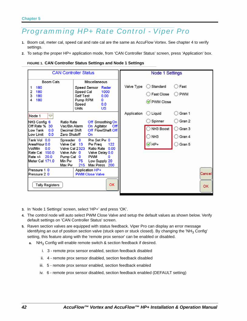
2. To setup the proper HP+ application mode, from ‘CAN Controller Status’ screen, press ‘Application’ box.
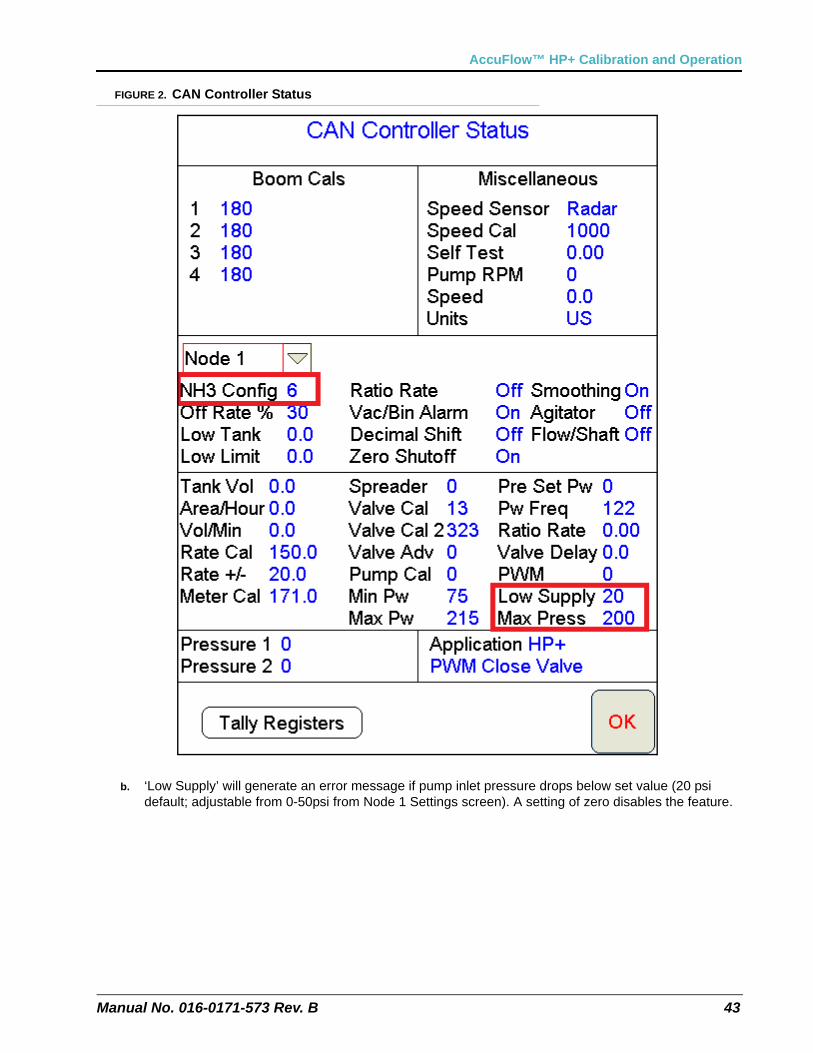
FIGURE 1. CAN Controller Status Settings and Node 1 Settings
3. In ‘Node 1 Settings’ screen, select ‘HP+’ and press ‘OK’.
4. The control node will auto select PWM Close Valve and setup the default values as shown below. Verify default settings on 'CAN Controller Status' screen.
5. Raven section valves are equipped with status feedback. Viper Pro can display an error message identifying an out of position section valve (stuck open or stuck closed). By changing the 'NH3 Config' setting, this feature along with the 'remote prox sensor' can be enabled or disabled.
a. NH3 Config will enable remote switch & section feedback if desired.
i. 3 - remote prox sensor enabled, section feedback disabled
ii. 4 - remote prox sensor disabled, section feedback disabled
iii. 5 - remote prox sensor enabled, section feedback enabled
iv. 6 - remote prox sensor disabled, section feedback enabled (DEFAULT setting)
Manual No. 016-0171-573 Rev. B 43
AccuFlow™ HP+ Calibration and Operation
FIGURE 2. CAN Controller Status
b. ‘Low Supply’ will generate an error message if pump inlet pressure drops below set value (20 psi default; adjustable from 0-50psi from Node 1 Settings screen). A setting of zero disables the feature.
Chapter 5
44 AccuFlow™ Vortex and AccuFlow™ HP+ Installation & Operation Manual
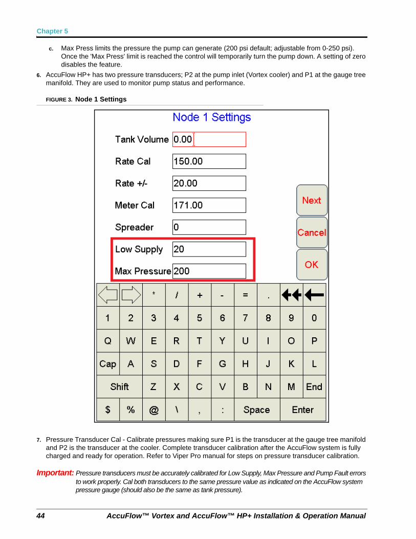
c. Max Press limits the pressure the pump can generate (200 psi default; adjustable from 0-250 psi). Once the 'Max Press' limit is reached the control will temporarily turn the pump down. A setting of zero disables the feature.
6. AccuFlow HP+ has two pressure transducers; P2 at the pump inlet (Vortex cooler) and P1 at the gauge tree manifold. They are used to monitor pump status and performance.
FIGURE 3. Node 1 Settings
7. Pressure Transducer Cal - Calibrate pressures making sure P1 is the transducer at the gauge tree manifold and P2 is the transducer at the cooler. Complete transducer calibration after the AccuFlow system is fully charged and ready for operation. Refer to Viper Pro manual for steps on pressure transducer calibration.
Important: Pressure transducers must be accurately calibrated for Low Supply, Max Pressure and Pump Fault errors to work properly. Cal both transducers to the same pressure value as indicated on the AccuFlow system pressure gauge (should also be the same as tank pressure).
Manual No. 016-0171-573 Rev. B 45
AccuFlow™ HP+ Calibration and Operation
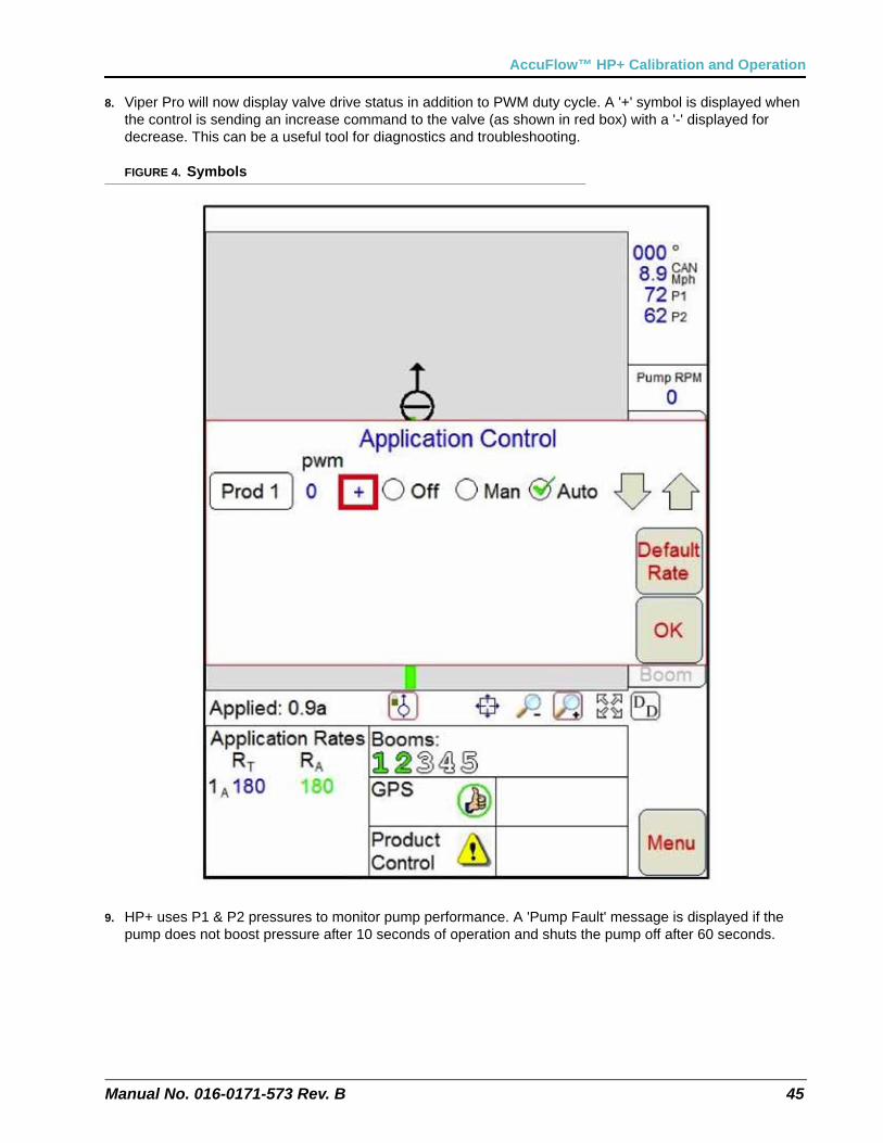
8. Viper Pro will now display valve drive status in addition to PWM duty cycle. A '+' symbol is displayed when the control is sending an increase command to the valve (as shown in red box) with a '-' displayed for decrease. This can be a useful tool for diagnostics and troubleshooting.
FIGURE 4. Symbols
9. HP+ uses P1 & P2 pressures to monitor pump performance. A 'Pump Fault' message is displayed if the pump does not boost pressure after 10 seconds of operation and shuts the pump off after 60 seconds.
Chapter 5
46 AccuFlow™ Vortex and AccuFlow™ HP+ Installation & Operation Manual
Adjusting the Rate Cal
Enter the target rate in actual pounds [kilograms] of nitrogen (N) per acre [hectare].
Calculating the Required Capacity
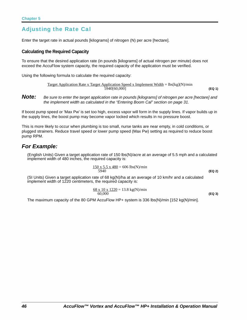
To ensure that the desired application rate (in pounds [kilograms] of actual nitrogen per minute) does not exceed the AccuFlow system capacity, the required capacity of the application must be verified.
Using the following formula to calculate the required capacity:
Target Application Rate x Target Application Speed x Implement Width = lbs[kg](N)/min5940[60,000] (EQ 1)
Note: Be sure to enter the target application rate in pounds [kilograms] of nitrogen per acre [hectare] and the implement width as calculated in the “Entering Boom Cal” section on page 31.
If boost pump speed or 'Max Pw' is set too high, excess vapor will form in the supply lines. If vapor builds up in the supply lines, the boost pump may become vapor locked which results in no pressure boost.
This is more likely to occur when plumbing is too small, nurse tanks are near empty, in cold conditions, or plugged strainers. Reduce travel speed or lower pump speed (Max Pw) setting as required to reduce boost pump RPM.
For Example:(English Units) Given a target application rate of 150 lbs(N)/acre at an average of 5.5 mph and a calculated implement width of 480 inches, the required capacity is:
150 x 5.5 x 480 = 606 lbs(N)/min5940.......................... (EQ 2)
(SI Units) Given a target application rate of 68 kg(N)/ha at an average of 10 km/hr and a calculated implement width of 1220 centimeters, the required capacity is:
68 x 10 x 1220 = 13.8 kg(N)/min60,000........................ (EQ 3)
The maximum capacity of the 80 GPM AccuFlow HP+ system is 336 lbs(N)/min [152 kg(N)/min].
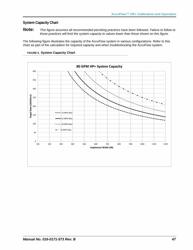
Manual No. 016-0171-573 Rev. B 47
AccuFlow™ HP+ Calibration and Operation
System Capacity Chart
Note: This figure assumes all recommended plumbing practices have been followed. Failure to follow to those practices will limit the system capacity to values lower than those shown on this figure.
The following figure illustrates the capacity of the AccuFlow system in various configurations. Refer to this chart as part of the calculation for required capacity and when troubleshooting the AccuFlow system.
FIGURE 5. System Capacity Chart
0
50
100
150
200
250
300
350
400
100 200 300 400 500 600 700 800 900 1000 1100 1200
Target
Rate
(LbN
/Acre)
Implement Width (IN)
80 GPM HP+ System Capacity
14 MPH Max
12 MPH Max
10 MPH Max
8 MPH Max
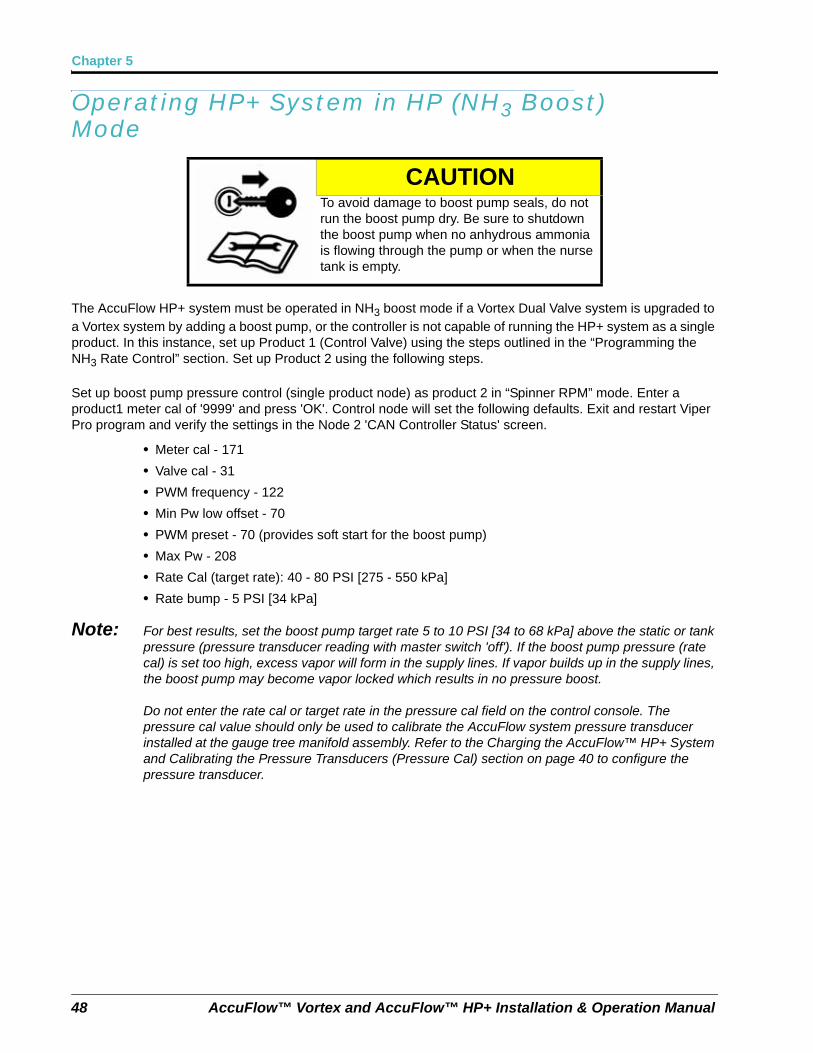
Chapter 5
48 AccuFlow™ Vortex and AccuFlow™ HP+ Installation & Operation Manual
Operating HP+ System in HP (NH3 Boost) Mode
The AccuFlow HP+ system must be operated in NH3 boost mode if a Vortex Dual Valve system is upgraded to a Vortex system by adding a boost pump, or the controller is not capable of running the HP+ system as a single product. In this instance, set up Product 1 (Control Valve) using the steps outlined in the “Programming the NH3 Rate Control” section. Set up Product 2 using the following steps.
Set up boost pump pressure control (single product node) as product 2 in “Spinner RPM” mode. Enter a product1 meter cal of '9999' and press 'OK'. Control node will set the following defaults. Exit and restart Viper Pro program and verify the settings in the Node 2 'CAN Controller Status' screen.
• Meter cal - 171
• Valve cal - 31
• PWM frequency - 122
• Min Pw low offset - 70
• PWM preset - 70 (provides soft start for the boost pump)
• Max Pw - 208
• Rate Cal (target rate): 40 - 80 PSI [275 - 550 kPa]
• Rate bump - 5 PSI [34 kPa]
Note: For best results, set the boost pump target rate 5 to 10 PSI [34 to 68 kPa] above the static or tank pressure (pressure transducer reading with master switch 'off'). If the boost pump pressure (rate cal) is set too high, excess vapor will form in the supply lines. If vapor builds up in the supply lines, the boost pump may become vapor locked which results in no pressure boost.
Do not enter the rate cal or target rate in the pressure cal field on the control console. The pressure cal value should only be used to calibrate the AccuFlow system pressure transducer installed at the gauge tree manifold assembly. Refer to the Charging the AccuFlow™ HP+ System and Calibrating the Pressure Transducers (Pressure Cal) section on page 40 to configure the pressure transducer.
CAUTIONTo avoid damage to boost pump seals, do not run the boost pump dry. Be sure to shutdown the boost pump when no anhydrous ammonia is flowing through the pump or when the nurse tank is empty.
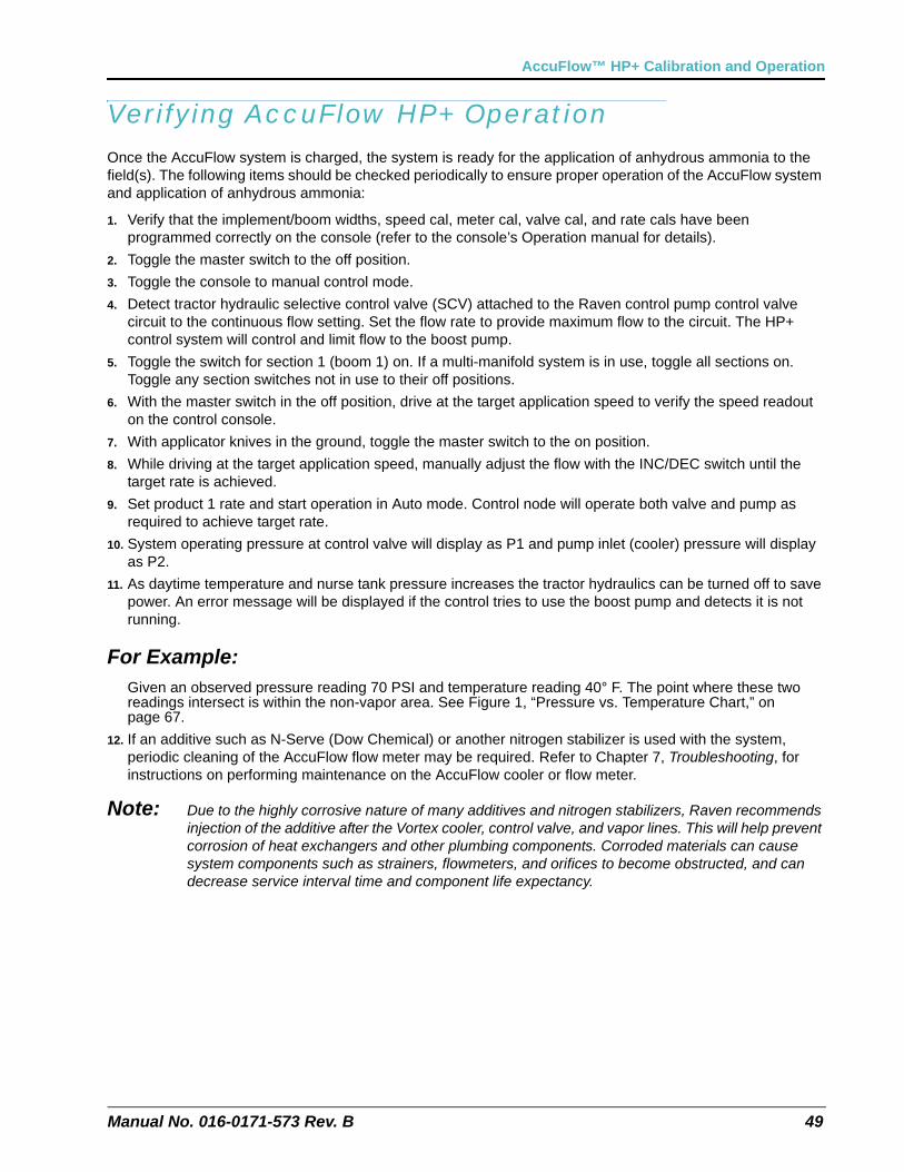
Manual No. 016-0171-573 Rev. B 49
AccuFlow™ HP+ Calibration and Operation
Verifying AccuFlow HP+ OperationOnce the AccuFlow system is charged, the system is ready for the application of anhydrous ammonia to the field(s). The following items should be checked periodically to ensure proper operation of the AccuFlow system and application of anhydrous ammonia:
1. Verify that the implement/boom widths, speed cal, meter cal, valve cal, and rate cals have been programmed correctly on the console (refer to the console’s Operation manual for details).
2. Toggle the master switch to the off position.
3. Toggle the console to manual control mode.
4. Detect tractor hydraulic selective control valve (SCV) attached to the Raven control pump control valve circuit to the continuous flow setting. Set the flow rate to provide maximum flow to the circuit. The HP+ control system will control and limit flow to the boost pump.
5. Toggle the switch for section 1 (boom 1) on. If a multi-manifold system is in use, toggle all sections on. Toggle any section switches not in use to their off positions.
6. With the master switch in the off position, drive at the target application speed to verify the speed readout on the control console.
7. With applicator knives in the ground, toggle the master switch to the on position.
8. While driving at the target application speed, manually adjust the flow with the INC/DEC switch until the target rate is achieved.
9. Set product 1 rate and start operation in Auto mode. Control node will operate both valve and pump as required to achieve target rate.
10. System operating pressure at control valve will display as P1 and pump inlet (cooler) pressure will display as P2.
11. As daytime temperature and nurse tank pressure increases the tractor hydraulics can be turned off to save power. An error message will be displayed if the control tries to use the boost pump and detects it is not running.
For Example:Given an observed pressure reading 70 PSI and temperature reading 40° F. The point where these two readings intersect is within the non-vapor area. See Figure 1, “Pressure vs. Temperature Chart,” on page 67.
12. If an additive such as N-Serve (Dow Chemical) or another nitrogen stabilizer is used with the system, periodic cleaning of the AccuFlow flow meter may be required. Refer to Chapter 7, Troubleshooting, for instructions on performing maintenance on the AccuFlow cooler or flow meter.
Note: Due to the highly corrosive nature of many additives and nitrogen stabilizers, Raven recommends injection of the additive after the Vortex cooler, control valve, and vapor lines. This will help prevent corrosion of heat exchangers and other plumbing components. Corroded materials can cause system components such as strainers, flowmeters, and orifices to become obstructed, and can decrease service interval time and component life expectancy.

Chapter 5
50 AccuFlow™ Vortex and AccuFlow™ HP+ Installation & Operation Manual
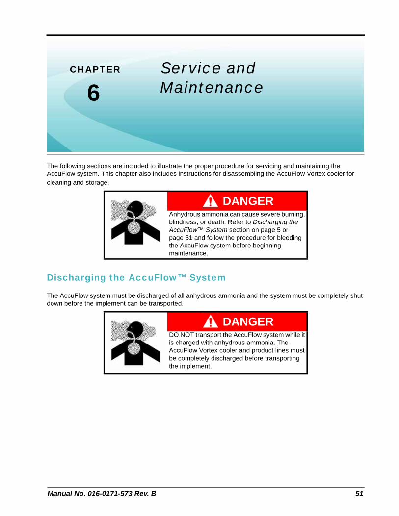
CHAPTER
6
Manual No. 016-0171-573 Rev. B 51
Chapter 6Service and Maintenance
The following sections are included to illustrate the proper procedure for servicing and maintaining the AccuFlow system. This chapter also includes instructions for disassembling the AccuFlow Vortex cooler for cleaning and storage.
Discharging the AccuFlow™ System
The AccuFlow system must be discharged of all anhydrous ammonia and the system must be completely shut down before the implement can be transported.
DANGERAnhydrous ammonia can cause severe burning, blindness, or death. Refer to Discharging the AccuFlow™ System section on page 5 or page 51 and follow the procedure for bleeding the AccuFlow system before beginning maintenance.
DANGERDO NOT transport the AccuFlow system while it is charged with anhydrous ammonia. The AccuFlow Vortex cooler and product lines must be completely discharged before transporting the implement.
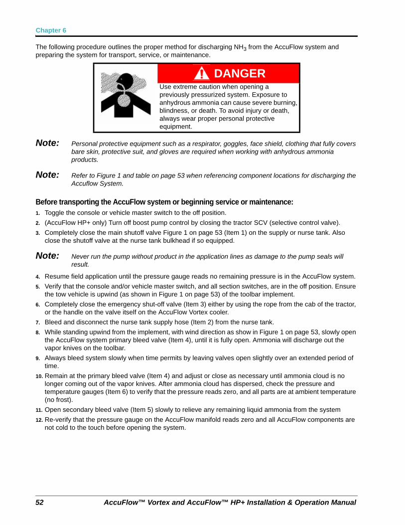
Chapter 6
52 AccuFlow™ Vortex and AccuFlow™ HP+ Installation & Operation Manual
The following procedure outlines the proper method for discharging NH3 from the AccuFlow system and preparing the system for transport, service, or maintenance.
Note: Personal protective equipment such as a respirator, goggles, face shield, clothing that fully covers bare skin, protective suit, and gloves are required when working with anhydrous ammonia products.
Note: Refer to Figure 1 and table on page 53 when referencing component locations for discharging the Accuflow System.
Before transporting the AccuFlow system or beginning service or maintenance:1. Toggle the console or vehicle master switch to the off position.
2. (AccuFlow HP+ only) Turn off boost pump control by closing the tractor SCV (selective control valve).
3. Completely close the main shutoff valve Figure 1 on page 53 (Item 1) on the supply or nurse tank. Also close the shutoff valve at the nurse tank bulkhead if so equipped.
Note: Never run the pump without product in the application lines as damage to the pump seals will result.
4. Resume field application until the pressure gauge reads no remaining pressure is in the AccuFlow system.
5. Verify that the console and/or vehicle master switch, and all section switches, are in the off position. Ensure the tow vehicle is upwind (as shown in Figure 1 on page 53) of the toolbar implement.
6. Completely close the emergency shut-off valve (Item 3) either by using the rope from the cab of the tractor, or the handle on the valve itself on the AccuFlow Vortex cooler.
7. Bleed and disconnect the nurse tank supply hose (Item 2) from the nurse tank.
8. While standing upwind from the implement, with wind direction as show in Figure 1 on page 53, slowly open the AccuFlow system primary bleed valve (Item 4), until it is fully open. Ammonia will discharge out the vapor knives on the toolbar.
9. Always bleed system slowly when time permits by leaving valves open slightly over an extended period of time.
10. Remain at the primary bleed valve (Item 4) and adjust or close as necessary until ammonia cloud is no longer coming out of the vapor knives. After ammonia cloud has dispersed, check the pressure and temperature gauges (Item 6) to verify that the pressure reads zero, and all parts are at ambient temperature (no frost).
11. Open secondary bleed valve (Item 5) slowly to relieve any remaining liquid ammonia from the system
12. Re-verify that the pressure gauge on the AccuFlow manifold reads zero and all AccuFlow components are not cold to the touch before opening the system.
DANGERUse extreme caution when opening a previously pressurized system. Exposure to anhydrous ammonia can cause severe burning, blindness, or death. To avoid injury or death, always wear proper personal protective equipment.
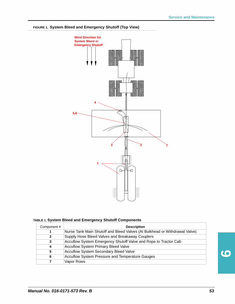
6
Manual No. 016-0171-573 Rev. B 53
Service and Maintenance
FIGURE 1. System Bleed and Emergency Shutoff (Top View)
TABLE 1. System Bleed and Emergency Shutoff Components
Component # Description1 Nurse Tank Main Shutoff and Bleed Valves (At Bulkhead or Withdrawal Valve)2 Supply Hose Bleed Valves and Breakaway Couplers3 Accuflow System Emergency Shutoff Valve and Rope to Tractor Cab4 Accuflow System Primary Bleed Valve5 Accuflow System Secondary Bleed Valve6 Accuflow System Pressure and Temperature Gauges7 Vapor Rows
Wind Direction for System Bleed or Emergency Shutoff
1
23
4
5,6
7
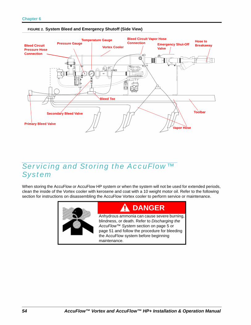
Chapter 6
54 AccuFlow™ Vortex and AccuFlow™ HP+ Installation & Operation Manual
FIGURE 2. System Bleed and Emergency Shutoff (Side View)
Servicing and Storing the AccuFlow™ SystemWhen storing the AccuFlow or AccuFlow HP system or when the system will not be used for extended periods, clean the inside of the Vortex cooler with kerosene and coat with a 10 weight motor oil. Refer to the following section for instructions on disassembling the AccuFlow Vortex cooler to perform service or maintenance.
DANGERAnhydrous ammonia can cause severe burning, blindness, or death. Refer to Discharging the AccuFlow™ System section on page 5 or page 51 and follow the procedure for bleeding the AccuFlow system before beginning maintenance.
Primary Bleed Valve
Secondary Bleed Valve
Bleed Tee
Vapor Hose
Toolbar
Hose to Breakaway
Pressure GaugeTemperature Gauge
Vortex Cooler
Bleed Circuit Vapor Hose Connection Emergency Shut-Off
ValveBleed Circuit Pressure Hose Connection
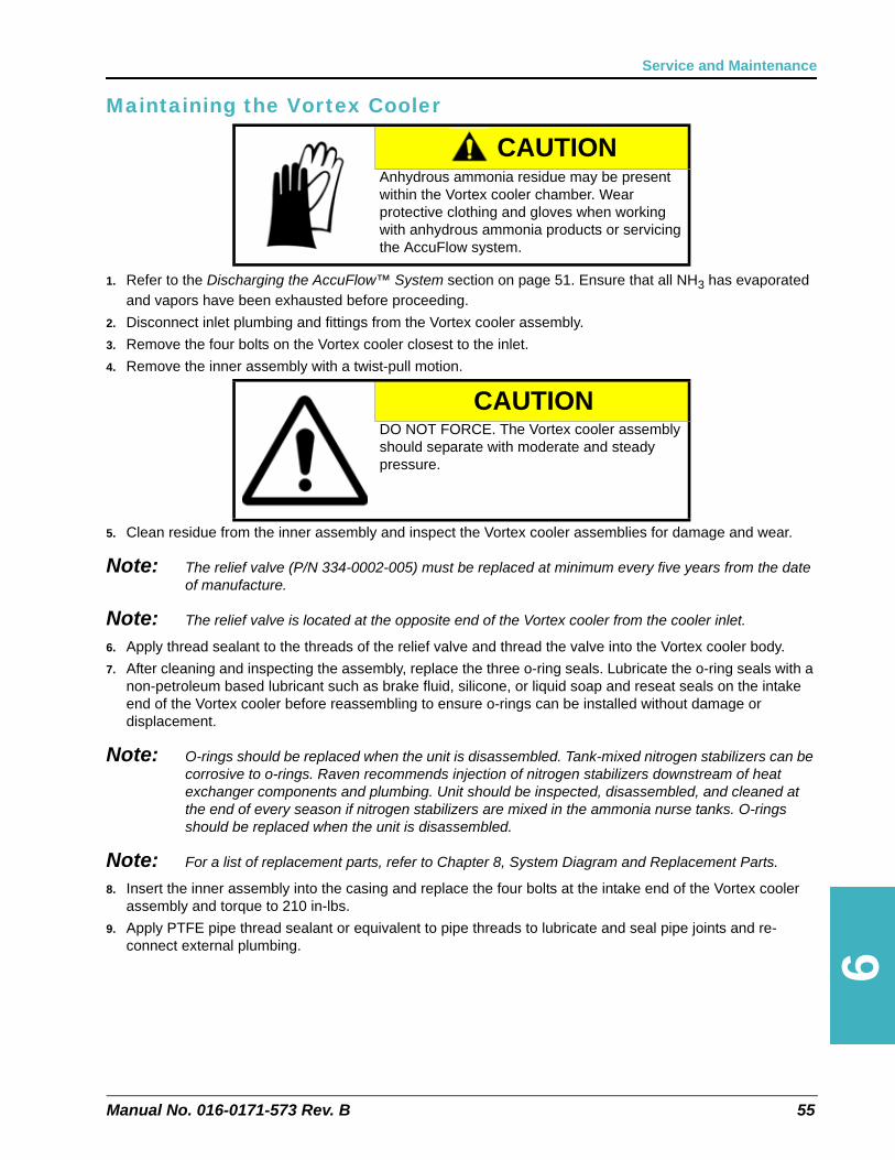
6
Manual No. 016-0171-573 Rev. B 55
Service and Maintenance
Maintaining the Vortex Cooler
1. Refer to the Discharging the AccuFlow™ System section on page 51. Ensure that all NH3 has evaporated and vapors have been exhausted before proceeding.
2. Disconnect inlet plumbing and fittings from the Vortex cooler assembly.
3. Remove the four bolts on the Vortex cooler closest to the inlet.
4. Remove the inner assembly with a twist-pull motion.
5. Clean residue from the inner assembly and inspect the Vortex cooler assemblies for damage and wear.
Note: The relief valve (P/N 334-0002-005) must be replaced at minimum every five years from the date of manufacture.
Note: The relief valve is located at the opposite end of the Vortex cooler from the cooler inlet.
6. Apply thread sealant to the threads of the relief valve and thread the valve into the Vortex cooler body.
7. After cleaning and inspecting the assembly, replace the three o-ring seals. Lubricate the o-ring seals with a non-petroleum based lubricant such as brake fluid, silicone, or liquid soap and reseat seals on the intake end of the Vortex cooler before reassembling to ensure o-rings can be installed without damage or displacement.
Note: O-rings should be replaced when the unit is disassembled. Tank-mixed nitrogen stabilizers can be corrosive to o-rings. Raven recommends injection of nitrogen stabilizers downstream of heat exchanger components and plumbing. Unit should be inspected, disassembled, and cleaned at the end of every season if nitrogen stabilizers are mixed in the ammonia nurse tanks. O-rings should be replaced when the unit is disassembled.
Note: For a list of replacement parts, refer to Chapter 8, System Diagram and Replacement Parts.
8. Insert the inner assembly into the casing and replace the four bolts at the intake end of the Vortex cooler assembly and torque to 210 in-lbs.
9. Apply PTFE pipe thread sealant or equivalent to pipe threads to lubricate and seal pipe joints and re-connect external plumbing.
CAUTIONAnhydrous ammonia residue may be present within the Vortex cooler chamber. Wear protective clothing and gloves when working with anhydrous ammonia products or servicing the AccuFlow system.
CAUTIONDO NOT FORCE. The Vortex cooler assembly should separate with moderate and steady pressure.
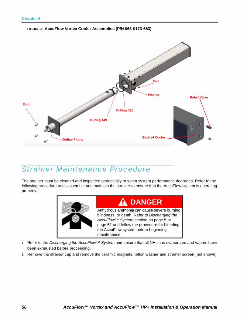
Chapter 6
56 AccuFlow™ Vortex and AccuFlow™ HP+ Installation & Operation Manual
FIGURE 3. AccuFlow Vortex Cooler Assemblies (P/N 063-0173-663)
Strainer Maintenance ProcedureThe strainer must be cleaned and inspected periodically or when system performance degrades. Refer to the following procedure to disassemble and maintain the strainer to ensure that the AccuFlow system is operating properly.
1. Refer to the Discharging the AccuFlow™ System and ensure that all NH3 has evaporated and vapors have been exhausted before proceeding.
2. Remove the strainer cap and remove the ceramic magnets, teflon washer and strainer screen (not shown).
DANGERAnhydrous ammonia can cause severe burning, blindness, or death. Refer to Discharging the AccuFlow™ System section on page 5 or page 51 and follow the procedure for bleeding the AccuFlow system before beginning maintenance.
Bolt
Orifice Fitting
O-Ring 421
O-Ring 149
Nut
Washer
Back of Cooler
Relief Valve
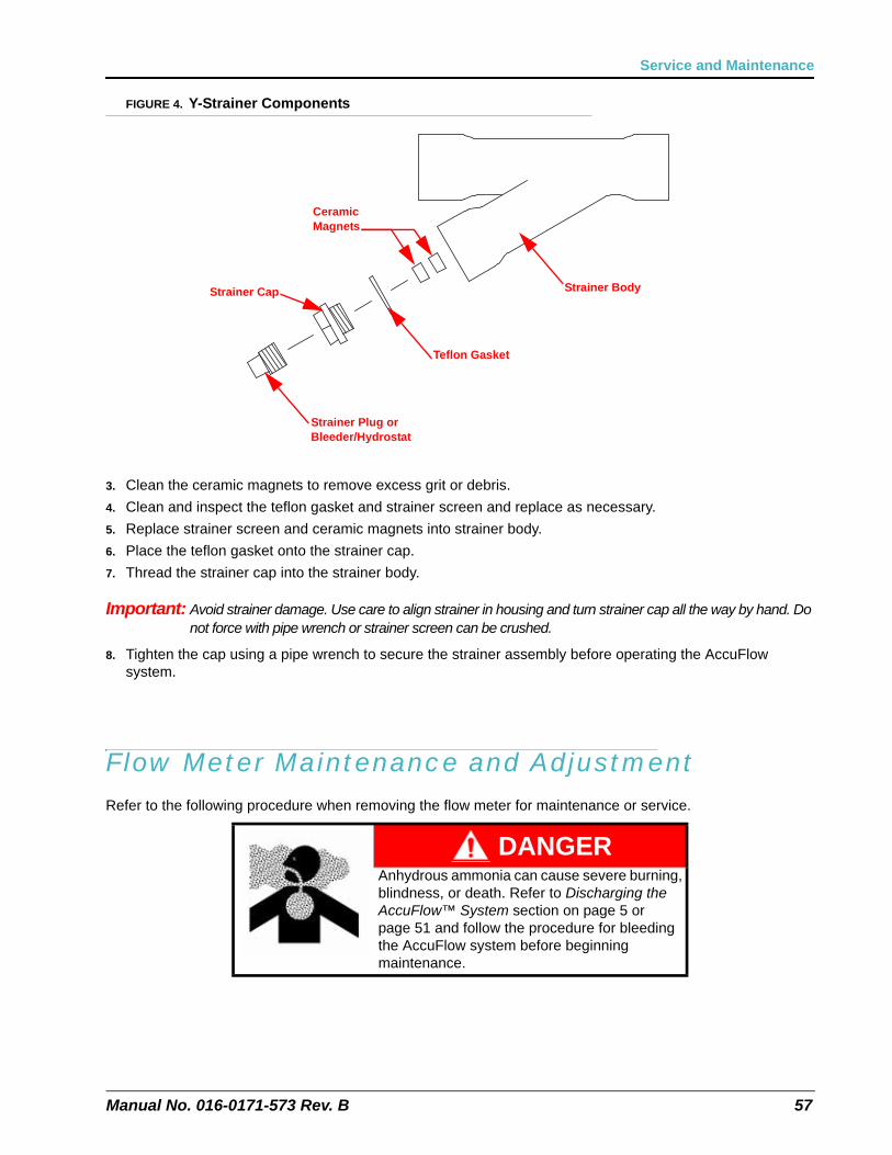
Manual No. 016-0171-573 Rev. B 57
Service and Maintenance
FIGURE 4. Y-Strainer Components
3. Clean the ceramic magnets to remove excess grit or debris.
4. Clean and inspect the teflon gasket and strainer screen and replace as necessary.
5. Replace strainer screen and ceramic magnets into strainer body.
6. Place the teflon gasket onto the strainer cap.
7. Thread the strainer cap into the strainer body.
Important: Avoid strainer damage. Use care to align strainer in housing and turn strainer cap all the way by hand. Do not force with pipe wrench or strainer screen can be crushed.
8. Tighten the cap using a pipe wrench to secure the strainer assembly before operating the AccuFlow system.
Flow Meter Maintenance and AdjustmentRefer to the following procedure when removing the flow meter for maintenance or service.
DANGERAnhydrous ammonia can cause severe burning, blindness, or death. Refer to Discharging the AccuFlow™ System section on page 5 or page 51 and follow the procedure for bleeding the AccuFlow system before beginning maintenance.
Strainer Body
Ceramic Magnets
Teflon Gasket
Strainer Cap
Strainer Plug or Bleeder/Hydrostat
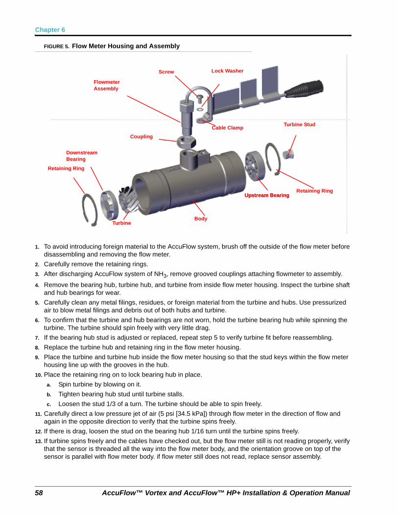
Chapter 6
58 AccuFlow™ Vortex and AccuFlow™ HP+ Installation & Operation Manual
FIGURE 5. Flow Meter Housing and Assembly
1. To avoid introducing foreign material to the AccuFlow system, brush off the outside of the flow meter before disassembling and removing the flow meter.
2. Carefully remove the retaining rings.
3. After discharging AccuFlow system of NH3, remove grooved couplings attaching flowmeter to assembly.
4. Remove the bearing hub, turbine hub, and turbine from inside flow meter housing. Inspect the turbine shaft and hub bearings for wear.
5. Carefully clean any metal filings, residues, or foreign material from the turbine and hubs. Use pressurized air to blow metal filings and debris out of both hubs and turbine.
6. To confirm that the turbine and hub bearings are not worn, hold the turbine bearing hub while spinning the turbine. The turbine should spin freely with very little drag.
7. If the bearing hub stud is adjusted or replaced, repeat step 5 to verify turbine fit before reassembling.
8. Replace the turbine hub and retaining ring in the flow meter housing.
9. Place the turbine and turbine hub inside the flow meter housing so that the stud keys within the flow meter housing line up with the grooves in the hub.
10. Place the retaining ring on to lock bearing hub in place.
a. Spin turbine by blowing on it.
b. Tighten bearing hub stud until turbine stalls.
c. Loosen the stud 1/3 of a turn. The turbine should be able to spin freely.
11. Carefully direct a low pressure jet of air (5 psi [34.5 kPa]) through flow meter in the direction of flow and again in the opposite direction to verify that the turbine spins freely.
12. If there is drag, loosen the stud on the bearing hub 1/16 turn until the turbine spins freely.
13. If turbine spins freely and the cables have checked out, but the flow meter still is not reading properly, verify that the sensor is threaded all the way into the flow meter body, and the orientation groove on top of the sensor is parallel with flow meter body. if flow meter still does not read, replace sensor assembly.
Turbine Stud
Retaining Ring
Upstream Bearing
Downstream Bearing
Retaining Ring
BodyTurbine
Flowmeter Assembly
Screw
Upstream Bearing
Cable Clamp
Coupling
Lock Washer

Manual No. 016-0171-573 Rev. B 59
Service and Maintenance
14. Re-connect the flowmeter to the system plumbing. Ensure gaskets on couplings slide over the piping and flowmeter body, centering gasket between components. Lubrication with soap may be required. Attach coupler clamp and re-torque hardware to 80-100 ft-lbs.
Note: For a list of replacement parts, refer to Chapter 8, System Diagram and Replacement Parts.

Chapter 6
60 AccuFlow™ Vortex and AccuFlow™ HP+ Installation & Operation Manual
CHAPTER
7
Manual No. 016-0171-573 Rev. B 61
Chapter 7Troubleshooting
WARNINGAnhydrous ammonia may be under pressure. Before disconnecting any fittings or hoses, be sure to purge the system of all NH3 (see Discharging the AccuFlow™ System section on page 51).
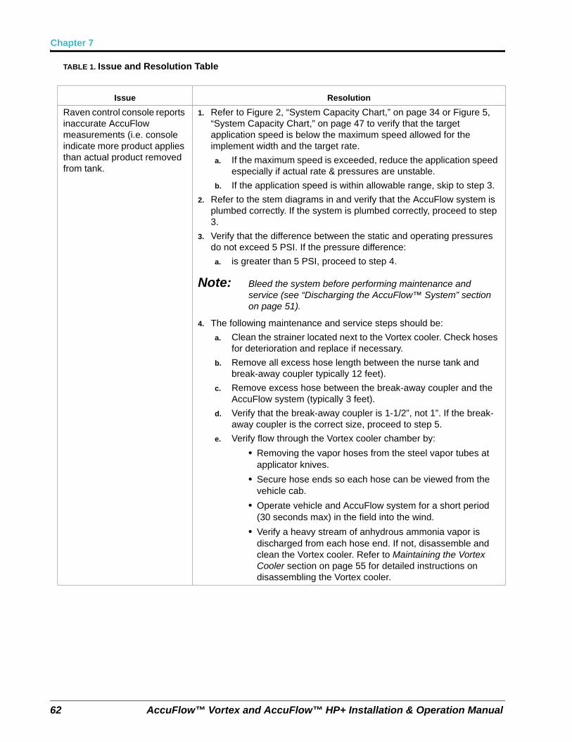
Chapter 7
62 AccuFlow™ Vortex and AccuFlow™ HP+ Installation & Operation Manual
TABLE 1. Issue and Resolution Table
Issue Resolution
Raven control console reports inaccurate AccuFlow measurements (i.e. console indicate more product applies than actual product removed from tank.
1. Refer to Figure 2, “System Capacity Chart,” on page 34 or Figure 5, “System Capacity Chart,” on page 47 to verify that the target application speed is below the maximum speed allowed for the implement width and the target rate.
a. If the maximum speed is exceeded, reduce the application speed especially if actual rate & pressures are unstable.
b. If the application speed is within allowable range, skip to step 3.
2. Refer to the stem diagrams in and verify that the AccuFlow system is plumbed correctly. If the system is plumbed correctly, proceed to step 3.
3. Verify that the difference between the static and operating pressures do not exceed 5 PSI. If the pressure difference:
a. is greater than 5 PSI, proceed to step 4.
Note: Bleed the system before performing maintenance and service (see “Discharging the AccuFlow™ System” section on page 51).
4. The following maintenance and service steps should be:
a. Clean the strainer located next to the Vortex cooler. Check hoses for deterioration and replace if necessary.
b. Remove all excess hose length between the nurse tank and break-away coupler typically 12 feet).
c. Remove excess hose between the break-away coupler and the AccuFlow system (typically 3 feet).
d. Verify that the break-away coupler is 1-1/2”, not 1”. If the break-away coupler is the correct size, proceed to step 5.
e. Verify flow through the Vortex cooler chamber by:
• Removing the vapor hoses from the steel vapor tubes at applicator knives.
• Secure hose ends so each hose can be viewed from the vehicle cab.
• Operate vehicle and AccuFlow system for a short period (30 seconds max) in the field into the wind.
• Verify a heavy stream of anhydrous ammonia vapor is discharged from each hose end. If not, disassemble and clean the Vortex cooler. Refer to Maintaining the Vortex Cooler section on page 55 for detailed instructions on disassembling the Vortex cooler.
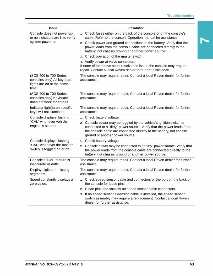
Manual No. 016-0171-573 Rev. B 63
Troubleshooting
7
Console does not power-up or no indicators are lit to verify system power-up.
1. Check fuses either on the back of the console or on the console’s cable. Refer to the console Operation manual for assistance.
2. Check power and ground connections to the battery. Verify that the power leads from the console cable are connected directly to the battery, not chassis ground or another power source.
3. Check operation of the master switch.
4. Verify power at valve connectorsIf none of the above steps resolve the issue, the console may require repair. Contact a local Raven dealer for further assistance.
(SCS 400 to 700 Series consoles only) All keyboard lights are on at the same time.
The console may require repair. Contact a local Raven dealer for further assistance.
(SCS 400 to 700 Series consoles only) Keyboard does not work for entries.
The console may require repair. Contact a local Raven dealer for further assistance.
Indicator light(s) on specific keys will not illuminate
The console may require repair. Contact a local Raven dealer for further assistance.
Console displays flashing “CAL” whenever vehicle engine is started.
1. Check battery voltage.
2. Console power may be toggled by the vehicle’s ignition switch or connected to a “dirty” power source. Verify that the power leads from the console cable are connected directly to the battery, not chassis ground or another power source.
Console displays flashing “CAL” whenever the master switch is toggled on or off.
1. Check battery voltage.
2. Console power may be connected to a “dirty” power source. Verify that the power leads from the console cable are connected directly to the battery, not chassis ground or another power source.
Console’s TIME feature is inaccurate or drifts.
The console may require repair. Contact a local Raven dealer for further assistance.
Display digits are missing segments.
The console may require repair. Contact a local Raven dealer for further assistance.
Speed constantly displays a zero value.
1. Check speed sensor cable and connectors or the port on the back of the console for loose pins.
2. Clean pins and sockets on speed sensor cable connectors.
3. If no speed sensor extension cable is installed, the speed sensor switch assembly may require a replacement. Contact a local Raven dealer for further assistance.
Issue Resolution
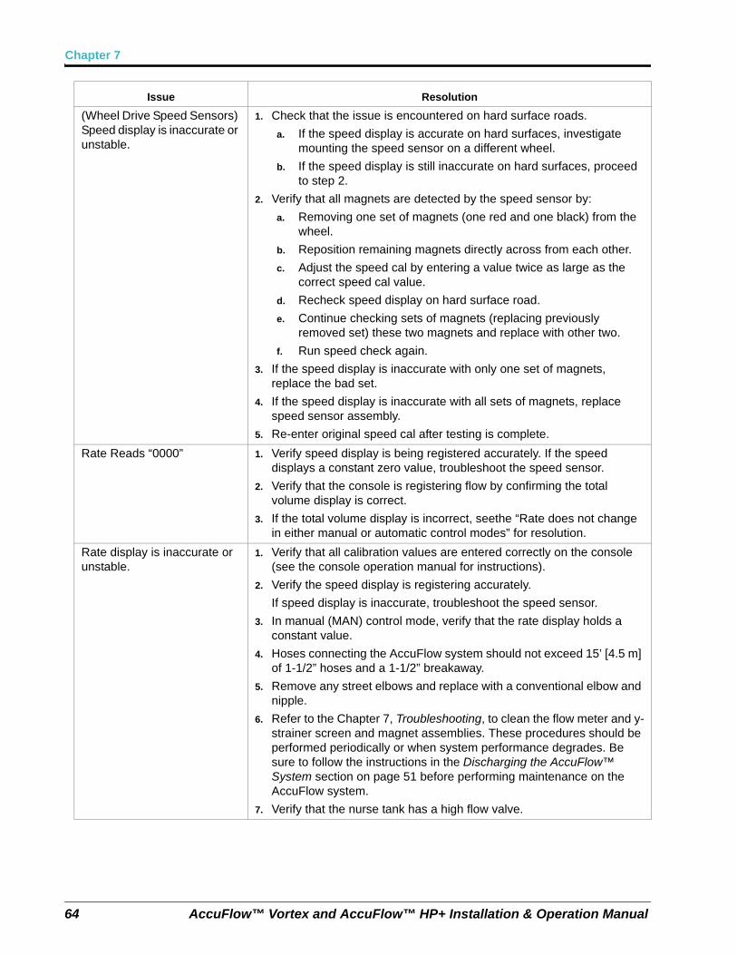
Chapter 7
64 AccuFlow™ Vortex and AccuFlow™ HP+ Installation & Operation Manual
(Wheel Drive Speed Sensors) Speed display is inaccurate or unstable.
1. Check that the issue is encountered on hard surface roads.
a. If the speed display is accurate on hard surfaces, investigate mounting the speed sensor on a different wheel.
b. If the speed display is still inaccurate on hard surfaces, proceed to step 2.
2. Verify that all magnets are detected by the speed sensor by:
a. Removing one set of magnets (one red and one black) from the wheel.
b. Reposition remaining magnets directly across from each other.
c. Adjust the speed cal by entering a value twice as large as the correct speed cal value.
d. Recheck speed display on hard surface road.
e. Continue checking sets of magnets (replacing previously removed set) these two magnets and replace with other two.
f. Run speed check again.
3. If the speed display is inaccurate with only one set of magnets, replace the bad set.
4. If the speed display is inaccurate with all sets of magnets, replace speed sensor assembly.
5. Re-enter original speed cal after testing is complete.
Rate Reads “0000” 1. Verify speed display is being registered accurately. If the speed displays a constant zero value, troubleshoot the speed sensor.
2. Verify that the console is registering flow by confirming the total volume display is correct.
3. If the total volume display is incorrect, seethe “Rate does not change in either manual or automatic control modes” for resolution.
Rate display is inaccurate or unstable.
1. Verify that all calibration values are entered correctly on the console (see the console operation manual for instructions).
2. Verify the speed display is registering accurately.
If speed display is inaccurate, troubleshoot the speed sensor.
3. In manual (MAN) control mode, verify that the rate display holds a constant value.
4. Hoses connecting the AccuFlow system should not exceed 15’ [4.5 m] of 1-1/2” hoses and a 1-1/2” breakaway.
5. Remove any street elbows and replace with a conventional elbow and nipple.
6. Refer to the Chapter 7, Troubleshooting, to clean the flow meter and y-strainer screen and magnet assemblies. These procedures should be performed periodically or when system performance degrades. Be sure to follow the instructions in the Discharging the AccuFlow™ System section on page 51 before performing maintenance on the AccuFlow system.
7. Verify that the nurse tank has a high flow valve.
Issue Resolution
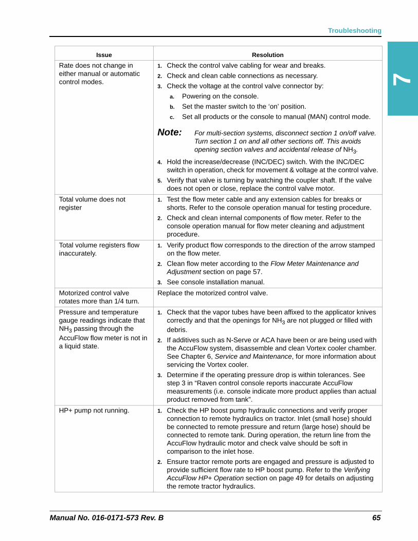
Manual No. 016-0171-573 Rev. B 65
Troubleshooting
7
Rate does not change in either manual or automatic control modes.
1. Check the control valve cabling for wear and breaks.
2. Check and clean cable connections as necessary.
3. Check the voltage at the control valve connector by:
a. Powering on the console.
b. Set the master switch to the ‘on’ position.
c. Set all products or the console to manual (MAN) control mode.
Note: For multi-section systems, disconnect section 1 on/off valve. Turn section 1 on and all other sections off. This avoids opening section valves and accidental release of NH3.
4. Hold the increase/decrease (INC/DEC) switch. With the INC/DEC switch in operation, check for movement & voltage at the control valve.
5. Verify that valve is turning by watching the coupler shaft. If the valve does not open or close, replace the control valve motor.
Total volume does not register
1. Test the flow meter cable and any extension cables for breaks or shorts. Refer to the console operation manual for testing procedure.
2. Check and clean internal components of flow meter. Refer to the console operation manual for flow meter cleaning and adjustment procedure.
Total volume registers flow inaccurately.
1. Verify product flow corresponds to the direction of the arrow stamped on the flow meter.
2. Clean flow meter according to the Flow Meter Maintenance and Adjustment section on page 57.
3. See console installation manual.
Motorized control valve rotates more than 1/4 turn.
Replace the motorized control valve.
Pressure and temperature gauge readings indicate that NH3 passing through the AccuFlow flow meter is not in a liquid state.
1. Check that the vapor tubes have been affixed to the applicator knives correctly and that the openings for NH3 are not plugged or filled with debris.
2. If additives such as N-Serve or ACA have been or are being used with the AccuFlow system, disassemble and clean Vortex cooler chamber. See Chapter 6, Service and Maintenance, for more information about servicing the Vortex cooler.
3. Determine if the operating pressure drop is within tolerances. See step 3 in “Raven control console reports inaccurate AccuFlow measurements (i.e. console indicate more product applies than actual product removed from tank”.
HP+ pump not running. 1. Check the HP boost pump hydraulic connections and verify proper connection to remote hydraulics on tractor. Inlet (small hose) should be connected to remote pressure and return (large hose) should be connected to remote tank. During operation, the return line from the AccuFlow hydraulic motor and check valve should be soft in comparison to the inlet hose.
2. Ensure tractor remote ports are engaged and pressure is adjusted to provide sufficient flow rate to HP boost pump. Refer to the Verifying AccuFlow HP+ Operation section on page 49 for details on adjusting the remote tractor hydraulics.
Issue Resolution
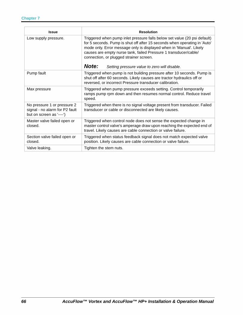
Chapter 7
66 AccuFlow™ Vortex and AccuFlow™ HP+ Installation & Operation Manual
Low supply pressure. Triggered when pump inlet pressure falls below set value (20 psi default) for 5 seconds. Pump is shut off after 15 seconds when operating in 'Auto' mode only. Error message only is displayed when in 'Manual'. Likely causes are empty nurse tank, failed Pressure 1 transducer/cable/connection, or plugged strainer screen.
Note: Setting pressure value to zero will disable.
Pump fault Triggered when pump is not building pressure after 10 seconds. Pump is shut off after 60 seconds. Likely causes are tractor hydraulics off or reversed, or incorrect Pressure transducer calibration.
Max pressure Triggered when pump pressure exceeds setting. Control temporarily ramps pump rpm down and then resumes normal control. Reduce travel speed.
No pressure 1 or pressure 2 signal - no alarm for P2 fault but on screen as '----')
Triggered when there is no signal voltage present from transducer. Failed transducer or cable or disconnected are likely causes.
Master valve failed open or closed.
Triggered when control node does not sense the expected change in master control valve's amperage draw upon reaching the expected end of travel. Likely causes are cable connection or valve failure.
Section valve failed open or closed.
Triggered when status feedback signal does not match expected valve position. Likely causes are cable connection or valve failure.
Valve leaking. Tighten the stem nuts.
Issue Resolution
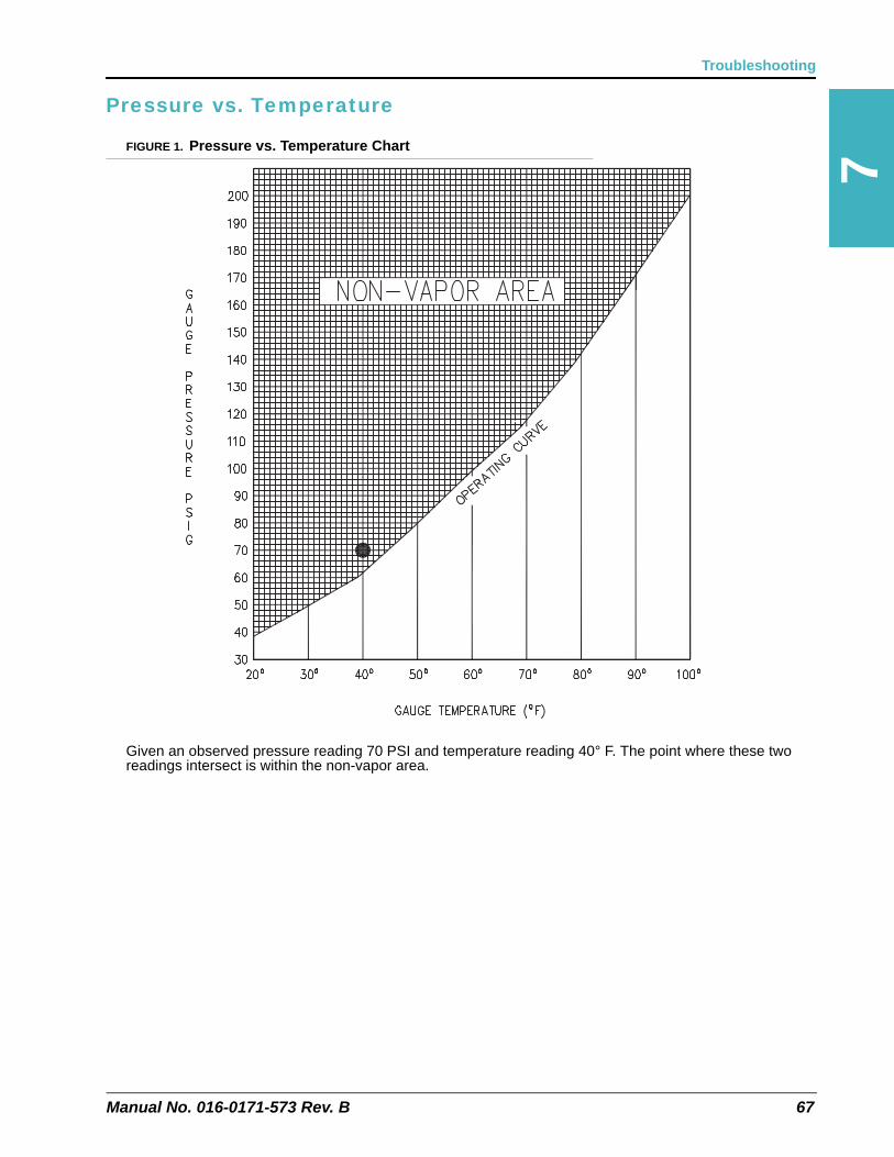
Manual No. 016-0171-573 Rev. B 67
Troubleshooting
7
Pressure vs. Temperature
FIGURE 1. Pressure vs. Temperature Chart
Given an observed pressure reading 70 PSI and temperature reading 40° F. The point where these two readings intersect is within the non-vapor area.
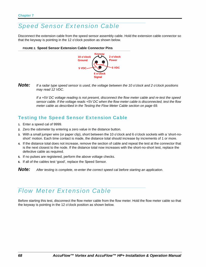
Chapter 7
68 AccuFlow™ Vortex and AccuFlow™ HP+ Installation & Operation Manual
Speed Sensor Extension CableDisconnect the extension cable from the speed sensor assembly cable. Hold the extension cable connector so that the keyway is pointing in the 12 o’clock position as shown below.
FIGURE 2. Speed Sensor Extension Cable Connector Pins
Note: If a radar type speed sensor is used, the voltage between the 10 o’clock and 2 o’clock positions may read 12 VDC.
If a +5V DC voltage reading is not present, disconnect the flow meter cable and re-test the speed sensor cable. If the voltage reads +5V DC when the flow meter cable is disconnected, test the flow meter cable as described in the Testing the Flow Meter Cable section on page 69.
Testing the Speed Sensor Extension Cable1. Enter a speed cal of 9999.
2. Zero the odometer by entering a zero value in the distance button.
3. With a small jumper wire (or paper clip), short between the 10 o’clock and 6 o’clock sockets with a ‘short-no-short’ motion. Each time contact is made, the distance total should increase by increments of 1 or more.
4. If the distance total does not increase, remove the section of cable and repeat the test at the connector that is the next closest to the node. If the distance total now increases with the short-no-short test, replace the defective cable as required.
5. If no pulses are registered, perform the above voltage checks.
6. If all of the cables test ‘good’, replace the Speed Sensor.
Note: After testing is complete, re-enter the correct speed cal before starting an application.
Flow Meter Extension CableBefore starting this test, disconnect the flow meter cable from the flow meter. Hold the flow meter cable so that the keyway is pointing in the 12 o’clock position as shown below.
10 o’clockGround
2 o’clockPower
Keyway
6 o’clockSignal
5 VDC5 VDC
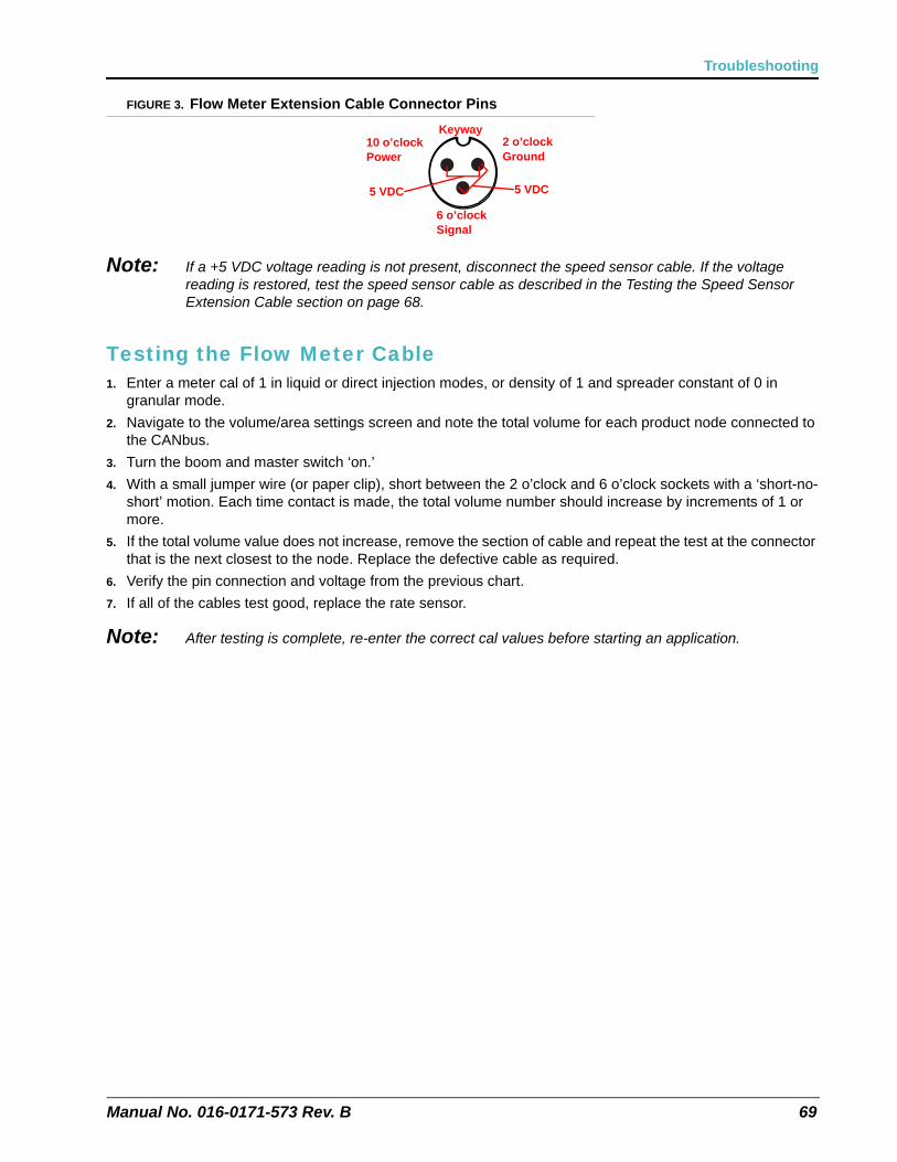
Manual No. 016-0171-573 Rev. B 69
Troubleshooting
FIGURE 3. Flow Meter Extension Cable Connector Pins
Note: If a +5 VDC voltage reading is not present, disconnect the speed sensor cable. If the voltage reading is restored, test the speed sensor cable as described in the Testing the Speed Sensor Extension Cable section on page 68.
Testing the Flow Meter Cable1. Enter a meter cal of 1 in liquid or direct injection modes, or density of 1 and spreader constant of 0 in
granular mode.
2. Navigate to the volume/area settings screen and note the total volume for each product node connected to the CANbus.
3. Turn the boom and master switch ‘on.’
4. With a small jumper wire (or paper clip), short between the 2 o’clock and 6 o’clock sockets with a ‘short-no-short’ motion. Each time contact is made, the total volume number should increase by increments of 1 or more.
5. If the total volume value does not increase, remove the section of cable and repeat the test at the connector that is the next closest to the node. Replace the defective cable as required.
6. Verify the pin connection and voltage from the previous chart.
7. If all of the cables test good, replace the rate sensor.
Note: After testing is complete, re-enter the correct cal values before starting an application.
10 o’clockPower
2 o’clockGround
Keyway
6 o’clockSignal
5 VDC5 VDC

Chapter 7
70 AccuFlow™ Vortex and AccuFlow™ HP+ Installation & Operation Manual
CHAPTER
8
Manual No. 016-0171-573 Rev. B 71
Chapter 8System Diagram and Replacement Parts
Standard AccuFlow™ DiagramsThe AccuFlow Vortex one and two valve systems may be operated using standard Raven SCS control cabling. Refer to the figure below for additional components used with the AccuFlow HP+ systems.
Note: Contact a local Raven dealer for additional information or assistance with cabling or Raven AccuFlow system components.
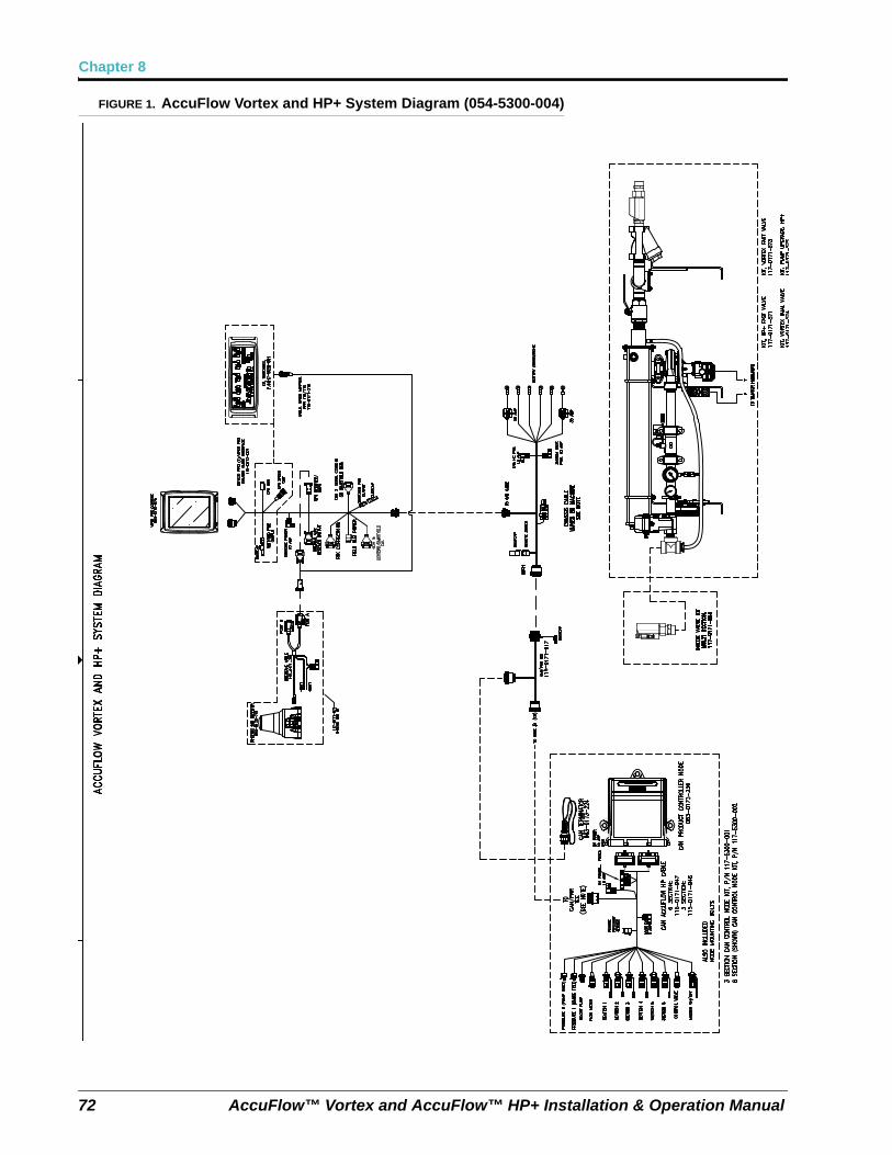
Chapter 8
72 AccuFlow™ Vortex and AccuFlow™ HP+ Installation & Operation Manual
FIGURE 1. AccuFlow Vortex and HP+ System Diagram (054-5300-004)
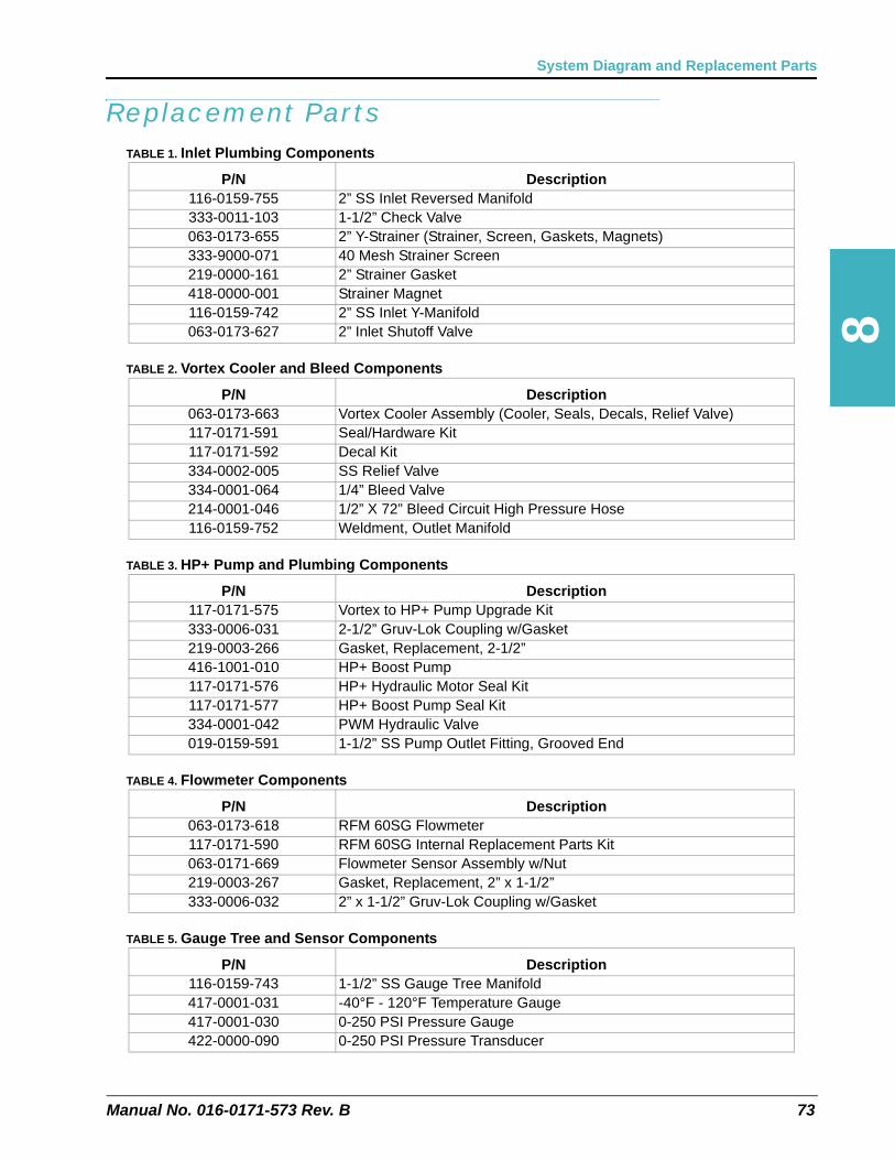
8
Manual No. 016-0171-573 Rev. B 73
System Diagram and Replacement Parts
Replacement PartsTABLE 1. Inlet Plumbing Components
TABLE 2. Vortex Cooler and Bleed Components
TABLE 3. HP+ Pump and Plumbing Components
TABLE 4. Flowmeter Components
TABLE 5. Gauge Tree and Sensor Components
P/N Description116-0159-755 2” SS Inlet Reversed Manifold333-0011-103 1-1/2” Check Valve063-0173-655 2” Y-Strainer (Strainer, Screen, Gaskets, Magnets)333-9000-071 40 Mesh Strainer Screen219-0000-161 2” Strainer Gasket418-0000-001 Strainer Magnet116-0159-742 2” SS Inlet Y-Manifold063-0173-627 2” Inlet Shutoff Valve
P/N Description063-0173-663 Vortex Cooler Assembly (Cooler, Seals, Decals, Relief Valve)117-0171-591 Seal/Hardware Kit117-0171-592 Decal Kit334-0002-005 SS Relief Valve334-0001-064 1/4” Bleed Valve 214-0001-046 1/2” X 72” Bleed Circuit High Pressure Hose116-0159-752 Weldment, Outlet Manifold
P/N Description117-0171-575 Vortex to HP+ Pump Upgrade Kit333-0006-031 2-1/2” Gruv-Lok Coupling w/Gasket219-0003-266 Gasket, Replacement, 2-1/2”416-1001-010 HP+ Boost Pump117-0171-576 HP+ Hydraulic Motor Seal Kit117-0171-577 HP+ Boost Pump Seal Kit334-0001-042 PWM Hydraulic Valve019-0159-591 1-1/2” SS Pump Outlet Fitting, Grooved End
P/N Description063-0173-618 RFM 60SG Flowmeter117-0171-590 RFM 60SG Internal Replacement Parts Kit063-0171-669 Flowmeter Sensor Assembly w/Nut219-0003-267 Gasket, Replacement, 2” x 1-1/2”333-0006-032 2” x 1-1/2” Gruv-Lok Coupling w/Gasket
P/N Description116-0159-743 1-1/2” SS Gauge Tree Manifold417-0001-031 -40°F - 120°F Temperature Gauge417-0001-030 0-250 PSI Pressure Gauge422-0000-090 0-250 PSI Pressure Transducer
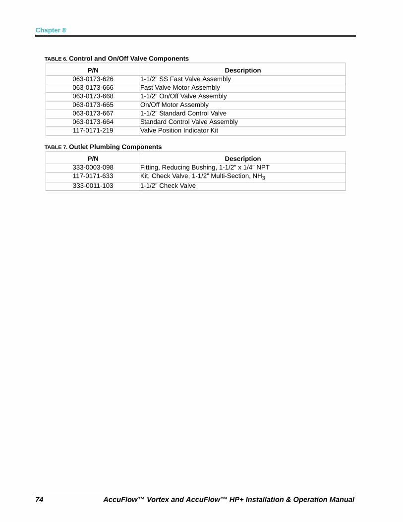
Chapter 8
74 AccuFlow™ Vortex and AccuFlow™ HP+ Installation & Operation Manual
TABLE 6. Control and On/Off Valve Components
TABLE 7. Outlet Plumbing Components
P/N Description063-0173-626 1-1/2” SS Fast Valve Assembly063-0173-666 Fast Valve Motor Assembly063-0173-668 1-1/2” On/Off Valve Assembly063-0173-665 On/Off Motor Assembly063-0173-667 1-1/2” Standard Control Valve063-0173-664 Standard Control Valve Assembly117-0171-219 Valve Position Indicator Kit
P/N Description333-0003-098 Fitting, Reducing Bushing, 1-1/2” x 1/4” NPT117-0171-633 Kit, Check Valve, 1-1/2” Multi-Section, NH3
333-0011-103 1-1/2” Check Valve
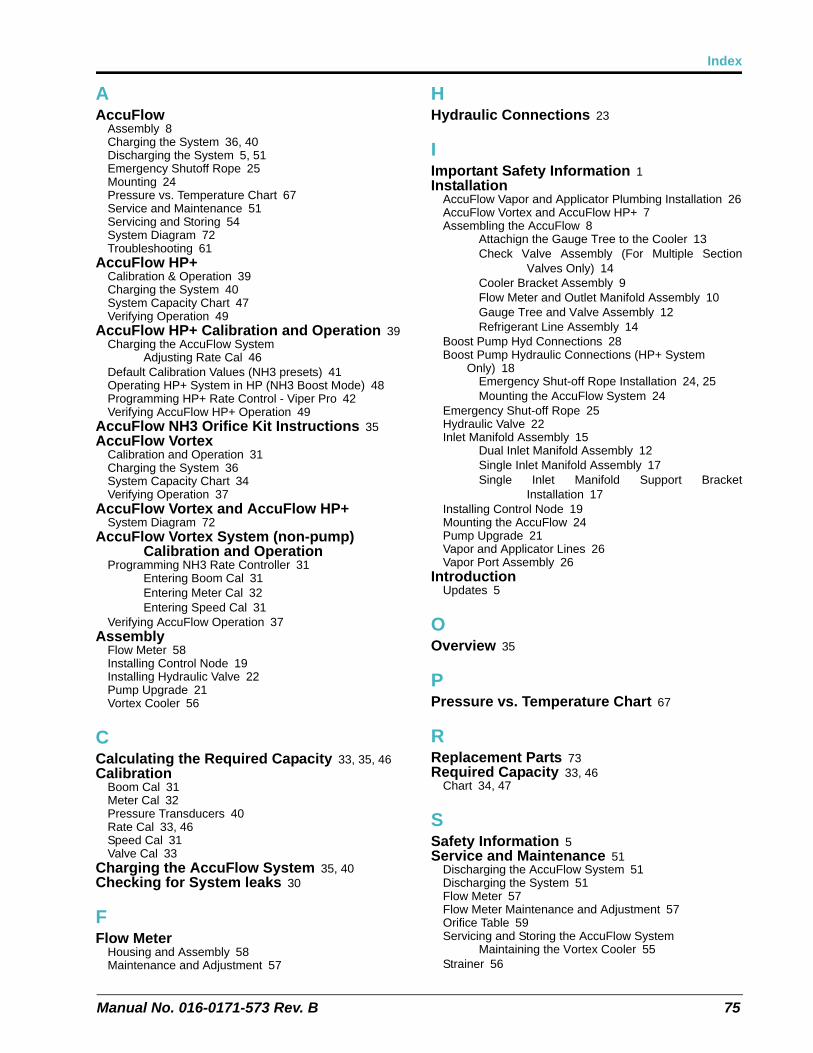
Index
Manual No. 016-0171-573 Rev. B 75
AAccuFlow
Assembly 8Charging the System 36, 40Discharging the System 5, 51Emergency Shutoff Rope 25Mounting 24Pressure vs. Temperature Chart 67Service and Maintenance 51Servicing and Storing 54System Diagram 72Troubleshooting 61
AccuFlow HP+Calibration & Operation 39Charging the System 40System Capacity Chart 47Verifying Operation 49
AccuFlow HP+ Calibration and Operation 39Charging the AccuFlow System
Adjusting Rate Cal 46Default Calibration Values (NH3 presets) 41Operating HP+ System in HP (NH3 Boost Mode) 48Programming HP+ Rate Control - Viper Pro 42Verifying AccuFlow HP+ Operation 49
AccuFlow NH3 Orifice Kit Instructions 35AccuFlow Vortex
Calibration and Operation 31Charging the System 36System Capacity Chart 34Verifying Operation 37
AccuFlow Vortex and AccuFlow HP+System Diagram 72
AccuFlow Vortex System (non-pump) Calibration and Operation
Programming NH3 Rate Controller 31Entering Boom Cal 31Entering Meter Cal 32Entering Speed Cal 31
Verifying AccuFlow Operation 37Assembly
Flow Meter 58Installing Control Node 19Installing Hydraulic Valve 22Pump Upgrade 21Vortex Cooler 56
CCalculating the Required Capacity 33, 35, 46Calibration
Boom Cal 31Meter Cal 32Pressure Transducers 40Rate Cal 33, 46Speed Cal 31Valve Cal 33
Charging the AccuFlow System 35, 40Checking for System leaks 30
FFlow Meter
Housing and Assembly 58Maintenance and Adjustment 57
HHydraulic Connections 23
IImportant Safety Information 1Installation
AccuFlow Vapor and Applicator Plumbing Installation 26AccuFlow Vortex and AccuFlow HP+ 7Assembling the AccuFlow 8
Attachign the Gauge Tree to the Cooler 13Check Valve Assembly (For Multiple Section
Valves Only) 14Cooler Bracket Assembly 9Flow Meter and Outlet Manifold Assembly 10Gauge Tree and Valve Assembly 12Refrigerant Line Assembly 14
Boost Pump Hyd Connections 28Boost Pump Hydraulic Connections (HP+ System
Only) 18Emergency Shut-off Rope Installation 24, 25Mounting the AccuFlow System 24
Emergency Shut-off Rope 25Hydraulic Valve 22Inlet Manifold Assembly 15
Dual Inlet Manifold Assembly 12Single Inlet Manifold Assembly 17Single Inlet Manifold Support Bracket
Installation 17Installing Control Node 19Mounting the AccuFlow 24Pump Upgrade 21Vapor and Applicator Lines 26Vapor Port Assembly 26
IntroductionUpdates 5
OOverview 35
PPressure vs. Temperature Chart 67
RReplacement Parts 73Required Capacity 33, 46
Chart 34, 47
SSafety Information 5Service and Maintenance 51
Discharging the AccuFlow System 51Discharging the System 51Flow Meter 57Flow Meter Maintenance and Adjustment 57Orifice Table 59Servicing and Storing the AccuFlow System
Maintaining the Vortex Cooler 55Strainer 56
Index
76 AccuFlow™ Vortex and AccuFlow™ HP+ Installation & Operation Manual
Strainer Maintenance Procedure 56Vortex Cooler 55
Servicing and Storing the AccuFlow System 54
System Capacity Chart 34, 47System Diagram 71System Diagram and Replacement Parts
Replacement Parts 73Standard Accuflow Diagrams 71
System Plumbing Component Recommendations 2
System Specifications 2
TTroubleshooting
Control Valve 65Flashing “CAL” 63Flow Meter Cable 69SCS 400 to 700 Series Consoles 63Speed Sensor Extension Cable 68Wheel Drive Speed Sensors 64
VVapor and Applicator Line Installation 26
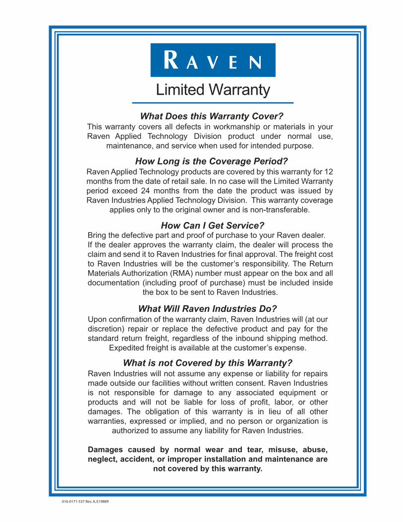
Raven Industries will not assume any expense or liability for repairs made outside our facilities without written consent. Raven Industries is not responsible for damage to any associated equipment or products and will not be liable for loss of profit, labor, or other damages. The obligation of this warranty is in lieu of all other warranties, expressed or implied, and no person or organization is
authorized to assume any liability for Raven Industries.
Damages caused by normal wear and tear, misuse, abuse, neglect, accident, or improper installation and maintenance are
not covered by this warranty.
What is not Covered by this Warranty?
Upon confirmation of the warranty claim, Raven Industries will (at our discretion) repair or replace the defective product and pay for the standard return freight, regardless of the inbound shipping method.
Expedited freight is available at the customer’s expense.
What Will Raven Industries Do?
Bring the defective part and proof of purchase to your Raven dealer.If the dealer approves the warranty claim, the dealer will process the claim and send it to Raven Industries for final approval. The freight cost to Raven Industries will be the customer’s responsibility. The Return Materials Authorization (RMA) number must appear on the box and all documentation (including proof of purchase) must be included inside
the box to be sent to Raven Industries.
How Can I Get Service?
Raven Applied Technology products are covered by this warranty for 12 months from the date of retail sale. In no case will the Limited Warranty period exceed 24 months from the date the product was issued by Raven Industries Applied Technology Division. This warranty coverage
applies only to the original owner and is non-transferable.
How Long is the Coverage Period?
This warranty covers all defects in workmanship or materials in your Raven Applied Technology Division product under normal use,
maintenance, and service when used for intended purpose.
What Does this Warranty Cover?
Limited Warranty
016-0171-537 Rev. A, E19889
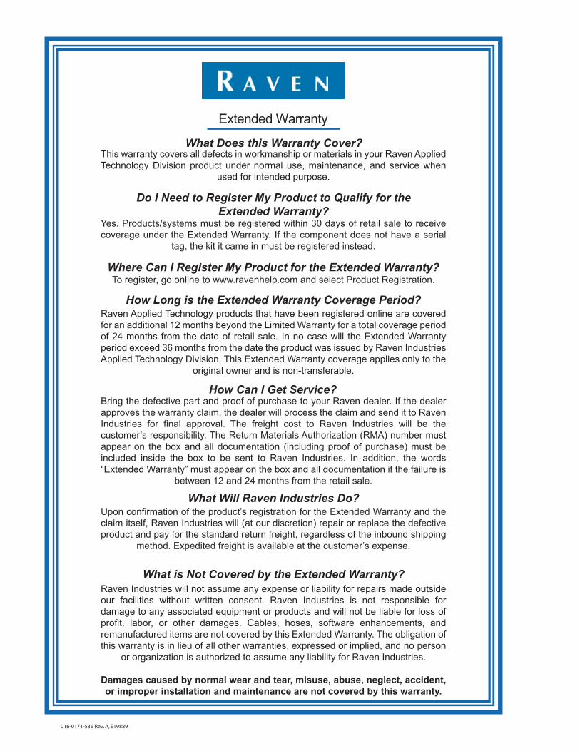
Raven Applied Technology products that have been registered online are covered for an additional 12 months beyond the Limited Warranty for a total coverage period of 24 months from the date of retail sale. In no case will the Extended Warranty period exceed 36 months from the date the product was issued by Raven Industries Applied Technology Division. This Extended Warranty coverage applies only to the
original owner and is non-transferable.
How Long is the Extended Warranty Coverage Period?
To register, go online to www.ravenhelp.com and select Product Registration.Where Can I Register My Product for the Extended Warranty?
Yes. Products/systems must be registered within 30 days of retail sale to receive coverage under the Extended Warranty. If the component does not have a serial
tag, the kit it came in must be registered instead.
Do I Need to Register My Product to Qualify for the Extended Warranty?
This warranty covers all defects in workmanship or materials in your Raven Applied Technology Division product under normal use, maintenance, and service when
used for intended purpose.
What Does this Warranty Cover?
Bring the defective part and proof of purchase to your Raven dealer. If the dealer approves the warranty claim, the dealer will process the claim and send it to Raven Industries for final approval. The freight cost to Raven Industries will be the customer’s responsibility. The Return Materials Authorization (RMA) number must appear on the box and all documentation (including proof of purchase) must be included inside the box to be sent to Raven Industries. In addition, the words “Extended Warranty” must appear on the box and all documentation if the failure is
between 12 and 24 months from the retail sale.
How Can I Get Service?
Upon confirmation of the product’s registration for the Extended Warranty and the claim itself, Raven Industries will (at our discretion) repair or replace the defective product and pay for the standard return freight, regardless of the inbound shipping
method. Expedited freight is available at the customer’s expense.
What Will Raven Industries Do?
Raven Industries will not assume any expense or liability for repairs made outside our facilities without written consent. Raven Industries is not responsible for damage to any associated equipment or products and will not be liable for loss of profit, labor, or other damages. Cables, hoses, software enhancements, and remanufactured items are not covered by this Extended Warranty. The obligation of this warranty is in lieu of all other warranties, expressed or implied, and no person
or organization is authorized to assume any liability for Raven Industries.
Damages caused by normal wear and tear, misuse, abuse, neglect, accident, or improper installation and maintenance are not covered by this warranty.
What is Not Covered by the Extended Warranty?
Extended Warranty
016-0171-536 Rev. A, E19889


Notice: This document and the information provided are the property of Raven Industries, Inc. and may only be used as authorized by Raven Industries, Inc. All rights reserved under copyright laws.
Raven IndustriesApplied Technology Division Toll Free (U.S. and Canada): (800)-243-5435P.O. Box 5107 or Outside the U.S. :1 605-575-0722Sioux Falls, SD 57117-5107 Fax: 605-331-0426
moc.plehnevar.www moc.noisicerpnevar.www
©Raven Industries, Inc. 2015
AccuFlowTM Vortex and AccuFlowTM HP+Installation & Operation Manual(P/N 016-0171-573 Rev B 01/15 E22987)