Embed Size (px)
Citation preview

GREASE INTERCEPTOR
GREASE INTERCEPTOR
GREASE INTERCEPTOR
GREASE INTERCEPTOR
GREASE INTERCEPTOR
GREASE INTERCEPTOR
GREASE INTERCEPTOR
GREASE INTERCEPTOR
GREASE INTERCEPTOR
GREASE INTERCEPTOR
GREASE INTERCEPTOR
GREASE INTERCEPTOR
INSTALLATION, OPERATION & MAINTENANCE
WARNING!As a plumbing appurtenance your Endura® grease interceptor MUST be isolated from the drainage system in the event that final drain testing or other system pressure testing is required. DO NOT under any circumstances subject your interceptor to pressure test (Air, Water or Otherwise). This action will result in damage to the unit, invalidate your warranty and could cause serious bodily injury.
XDO NOT PRESSURE TEST RISK OF SERIOUS INJURY
Manual 40100-3205/17
CanadaTel: (705) 726-3361 1-800-461-1771Fax: (705) 726-2186
U.S.ATel: (303) 373-1918 1-888-461-5307Fax: (303) 373-1923
*
Technical [email protected]
- 2 -
GREASE INTERCEPTOR
GREASE INTERCEPTOR
GREASE INTERCEPTOR
GREASE INTERCEPTOR
MANUALLIFTING POINTS
FACTORY PLUMBED 3-WAY OUTLET SYSTEM
REMOTE PUMP READY
AIR & WATER TIGHT EXTENSION SYSTEM
INTEGRATED LIFTING LOCATIONS
CLOSED RIBS FOR FLOTATION RESISTANCE
INTEGRATED TIE DOWN LOCATIONS
CORRUGATED WALLS FOR STRENGTH
LOAD RATED COVER & FRAME
CUT TO SUIT RISER EXTENSION
BUILT-IN HEIGHT ADJUSTMENT
AIR BALANCEDENVIRONMENT
TANK PROFILE RESISTS
FLOTATION
Features Overview
About Your Purchase:The Endura® XL grease interceptor and it associated products are the latest addition to the proven line of Endura® Grease Management products.
We have spent many thousands of hours in the development of Endura® XL, our aim being simple – to produce the industry’s best Hydromechanical Grease Interceptor.
From the ground up, Endura® XL has been ‘Engineered for Easy’. Working with distributors, installers, engineers, jurisdictional officials, pumpers and of course restaurant operators across North America, we have taken all of the feedback gained and rolled it into one comprehensively designed solution to meet as broad a range of these requirements as possible.
Endura® XL is the most widely evaluated and approved hydromechanical interceptor in the current marketplace, being successfully tested by independent third parties to meet all requirements of PDI G-101, ASME A112.14.3 (Type A & C) / NSF ES15741 and CSA B481.1.
*Endura brand products manufactured by Canplas Industries.
- 3 -
Glossary of Terms
Table of Contents
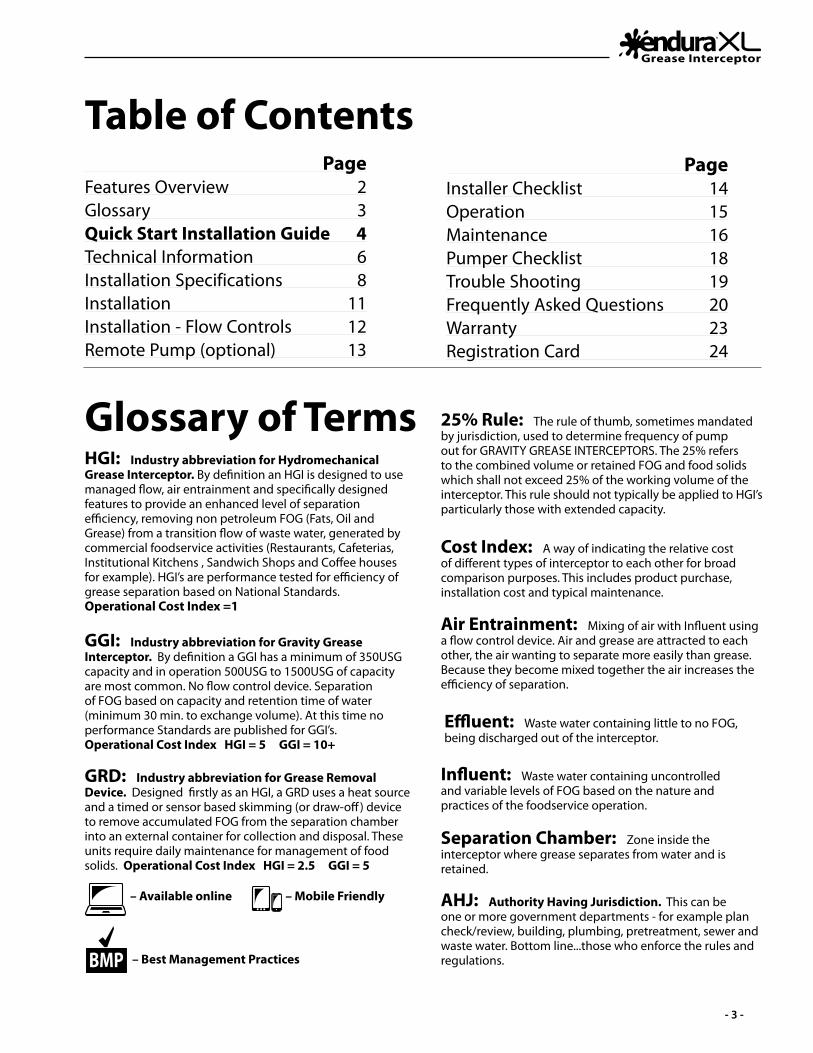
HGI: Industry abbreviation for Hydromechanical Grease Interceptor. By definition an HGI is designed to use managed flow, air entrainment and specifically designed features to provide an enhanced level of separation efficiency, removing non petroleum FOG (Fats, Oil and Grease) from a transition flow of waste water, generated by commercial foodservice activities (Restaurants, Cafeterias, Institutional Kitchens , Sandwich Shops and Coffee houses for example). HGI’s are performance tested for efficiency of grease separation based on National Standards. Operational Cost Index =1
GGI: Industry abbreviation for Gravity Grease Interceptor. By definition a GGI has a minimum of 350USG capacity and in operation 500USG to 1500USG of capacity are most common. No flow control device. Separation of FOG based on capacity and retention time of water (minimum 30 min. to exchange volume). At this time no performance Standards are published for GGI’s. Operational Cost Index HGI = 5 GGI = 10+
GRD: Industry abbreviation for Grease Removal Device. Designed firstly as an HGI, a GRD uses a heat source and a timed or sensor based skimming (or draw-off) device to remove accumulated FOG from the separation chamber into an external container for collection and disposal. These units require daily maintenance for management of food solids. Operational Cost Index HGI = 2.5 GGI = 5
AHJ: Authority Having Jurisdiction. This can be one or more government departments - for example plan check/review, building, plumbing, pretreatment, sewer and waste water. Bottom line...those who enforce the rules and regulations.
Cost Index: A way of indicating the relative cost of different types of interceptor to each other for broad comparison purposes. This includes product purchase, installation cost and typical maintenance.
25% Rule: The rule of thumb, sometimes mandated by jurisdiction, used to determine frequency of pump out for GRAVITY GREASE INTERCEPTORS. The 25% refers to the combined volume or retained FOG and food solids which shall not exceed 25% of the working volume of the interceptor. This rule should not typically be applied to HGI’s particularly those with extended capacity.
Air Entrainment: Mixing of air with Influent using a flow control device. Air and grease are attracted to each other, the air wanting to separate more easily than grease. Because they become mixed together the air increases the efficiency of separation.
Effluent: Waste water containing little to no FOG, being discharged out of the interceptor.
Influent: Waste water containing uncontrolled and variable levels of FOG based on the nature and practices of the foodservice operation.
Separation Chamber: Zone inside the interceptor where grease separates from water and is retained.
– Available online – Mobile Friendly
– Best Management PracticesBMP
PageFeatures Overview 2Glossary 3Quick Start Installation Guide 4Technical Information 6Installation Specifications 8Installation 11Installation - Flow Controls 12Remote Pump (optional) 13
PageInstaller Checklist 14Operation 15Maintenance 16Pumper Checklist 18Trouble Shooting 19Frequently Asked Questions 20Warranty 23Registration Card 24
Quick Start Guide
- 4 -
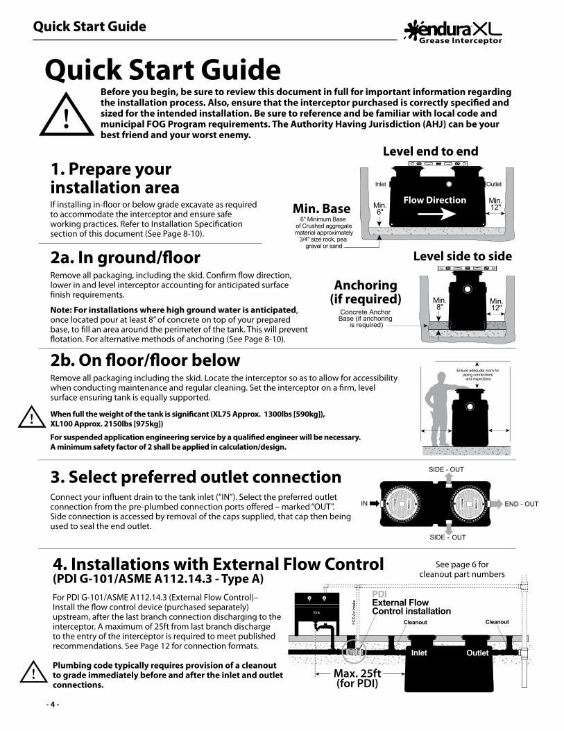
Quick Start GuideBefore you begin, be sure to review this document in full for important information regarding the installation process. Also, ensure that the interceptor purchased is correctly specified and sized for the intended installation. Be sure to reference and be familiar with local code and municipal FOG Program requirements. The Authority Having Jurisdiction (AHJ) can be your best friend and your worst enemy.
1. Prepare your installation areaIf installing in-floor or below grade excavate as required to accommodate the interceptor and ensure safe working practices. Refer to Installation Specification section of this document (See Page 8-10).
3. Select preferred outlet connection Connect your influent drain to the tank inlet (“IN”). Select the preferred outlet connection from the pre-plumbed connection ports offered – marked “OUT”. Side connection is accessed by removal of the caps supplied, that cap then being used to seal the end outlet.
2a. In ground/floorRemove all packaging, including the skid. Confirm flow direction, lower in and level interceptor accounting for anticipated surface finish requirements.
Note: For installations where high ground water is anticipated, once located pour at least 8” of concrete on top of your prepared base, to fill an area around the perimeter of the tank. This will prevent flotation. For alternative methods of anchoring (See Page 8-10).
2b. On floor/floor below Remove all packaging including the skid. Locate the interceptor so as to allow for accessibility when conducting maintenance and regular cleaning. Set the interceptor on a firm, level surface ensuring tank is equally supported.
When full the weight of the tank is significant (XL75 Approx. 1300lbs [590kg]), XL100 Approx. 2150lbs [975kg])
For suspended application engineering service by a qualified engineer will be necessary.A minimum safety factor of 2 shall be applied in calculation/design.
Concrete Anchor Base (if anchoring
is required)
Min.6"
Inlet Outlet
Min.12"
Min.12"
Min.8"
6" Minimum Base of Crushed aggregatematerial approximately
3/4" size rock, pea gravel or sand
Ensure adequate room for piping connections
and inspections
Ensure adequate room for piping connections
and inspections
GR
EASE
IN
TER
CEP
TORG
REA
SE INT
ERC
EPTO
RGR
EASE
IN
TER
CEP
TORG
REA
SE INT
ERC
EPTO
R
Cleanout
GR
EASE
IN
TER
CEP
TORG
REA
SE INT
ERC
EPTO
RGR
EASE
IN
TER
CEP
TORG
REA
SE INT
ERC
EPTO
R
OUTSIDE -
SIDE - OUT
END - OUTIN
OUTIN
Cleanout
CleanoutExternal Flow
Control
Cleanout
Max. 25ft
FCD
Air
Inta
ke
PDI External Flow
Control. Located as close as possible to
the last fixture
Cleanout Cleanout
Sink
Flow
Max. 25ft(for PDI)
PDI External Flow Control installation
CleanoutCleanoutFCD
Air
Inta
ke
Sink
Inlet Outlet
4. Installations with External Flow Control(PDI G-101/ASME A112.14.3 - Type A)
See page 6 forcleanout part numbers
Min. Base
Anchoring(if required)
Level end to end
Flow Direction
Level side to side
For PDI G-101/ASME A112.14.3 (External Flow Control)– Install the flow control device (purchased separately) upstream, after the last branch connection discharging to the interceptor. A maximum of 25ft from last branch discharge to the entry of the interceptor is required to meet published recommendations. See Page 12 for connection formats.
Plumbing code typically requires provision of a cleanout to grade immediately before and after the inlet and outlet connections.

Quick Start Guide
- 5 -
Nativesoil
Min.6"
Fill with water to static level
Fill with water to static level
Native soil
Concrete slab
Continue fill of Crushed aggregate
material approximately 3/4" size rock,
pea gravel or sand
Continue fill of Crushed aggregate
material approximately 3/4" size rock,
pea gravel or sand
6. Replace cover(s) and backfill Replace cover(s) and protect with cardboard or similar during back filling. Backfill per specification (See Page 8).
If installing Remote Pump option do so now (See Page 13)
5. Fill tank Fill tank with water to static water level. This provides stability and crush resistance during backfilling. Check connections made for any leaks.
For inspection testing DO NOT PRESSURE the tank. Plug lines inside interceptor to test upstream and downstream integrity.
7. Riser Extensions (optional)Depending on your application, extend the tank risers (using 40100AX35) to grade/floor level. Be sure to account for finishing. (Refer to Manual 40100X35-8 – Riser Extension Installation Guide)
8. Finish to grade / floorFor in ground applications with vehicular traffic, the upper 8” requires a reinforced concrete slab. Refer to the Installation Specification section of this document (See Page 8-9). This details backfill materials and concrete reinforcement requirements.
If installing in internal application with tiled floor, ensure adequate protection to prevent mortar from covering bolts, and/or entering around cover perimeter.
9. Completion documentationHaving completed installation and successful inspection, hand-over to the client all installation documentation, with page 14 completed. Fill out your sections of the Limited Lifetime warranty registration (See Page 24).
If submitting on behalf of your client you can do so at www.EnduraWarranty.com or by sending to the locations shown on the back cover of this document.
72”Maximum
height
72”Maximum
height
Vehicular traffic reinforced concrete
Reinforced concrete pad for traffic rated installations
8"
8"
WARNING!X
DO NOT PRESSURE TEST.
RISK OF SERIOUS INJURY.
For Spec See Page 8-9
Technical Information
- 6 -
19
13
9
10
1 12 23 34 4
1112
15
14
20 21
22
18
16 17
Mechanical Joint couplings
(by others)
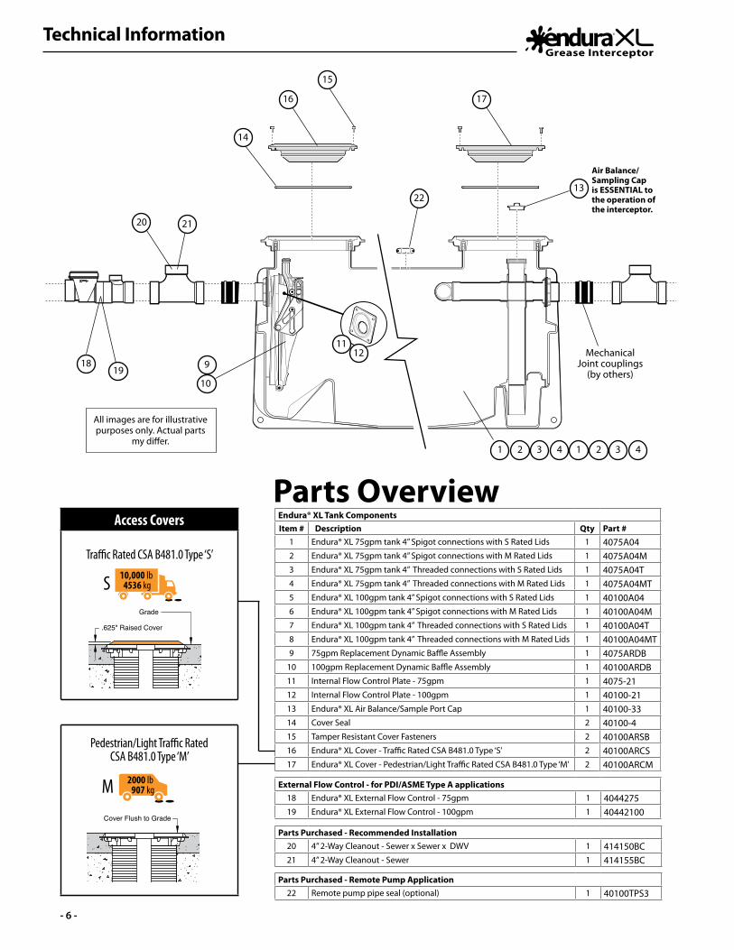
All images are for illustrative purposes only. Actual parts
my differ.
Air Balance/Sampling Cap is ESSENTIAL to the operation of the interceptor.
Endura® XL Tank ComponentsItem # Description Qty Part #
1 Endura® XL 75gpm tank 4” Spigot connections with S Rated Lids 1 4075A042 Endura® XL 75gpm tank 4” Spigot connections with M Rated Lids 1 4075A04M3 Endura® XL 75gpm tank 4” Threaded connections with S Rated Lids 1 4075A04T4 Endura® XL 75gpm tank 4” Threaded connections with M Rated Lids 1 4075A04MT5 Endura® XL 100gpm tank 4” Spigot connections with S Rated Lids 1 40100A046 Endura® XL 100gpm tank 4” Spigot connections with M Rated Lids 1 40100A04M7 Endura® XL 100gpm tank 4” Threaded connections with S Rated Lids 1 40100A04T8 Endura® XL 100gpm tank 4” Threaded connections with M Rated Lids 1 40100A04MT9 75gpm Replacement Dynamic Baffle Assembly 1 4075ARDB
10 100gpm Replacement Dynamic Baffle Assembly 1 40100ARDB11 Internal Flow Control Plate - 75gpm 1 4075-2112 Internal Flow Control Plate - 100gpm 1 40100-2113 Endura® XL Air Balance/Sample Port Cap 1 40100-3314 Cover Seal 2 40100-415 Tamper Resistant Cover Fasteners 2 40100ARSB16 Endura® XL Cover - Traffic Rated CSA B481.0 Type ‘S’ 2 40100ARCS17 Endura® XL Cover - Pedestrian/Light Traffic Rated CSA B481.0 Type ‘M’ 2 40100ARCM
External Flow Control - for PDI/ASME Type A applications18 Endura® XL External Flow Control - 75gpm 1 404427519 Endura® XL External Flow Control - 100gpm 1 40442100
Parts Purchased - Recommended Installation20 4” 2-Way Cleanout - Sewer x Sewer x DWV 1 414150BC21 4” 2-Way Cleanout - Sewer 1 414155BC
Parts Purchased - Remote Pump Application22 Remote pump pipe seal (optional) 1 40100TPS3
Parts OverviewAccess Covers
Traffic Rated CSA B481.0 Type ‘S’
Pedestrian/Light Traffic Rated CSA B481.0 Type ‘M’
Grade
.625" Raised Cover
Cover Flush to Grade
Grade
.625" Raised Cover
Cover Flush to Grade
2000 lb 907 kg300 lb
135 kg
300 lb 135 kg
10,000 lb 4536 kg
M
2000 lb 907 kg300 lb
135 kg
300 lb 135 kg
10,000 lb 4536 kgS
Technical Information
- 7 -
Specification:Sample specification clause.Contractor shall install a Endura® XL Hydromechanical Grease Interceptor (HGI), Part No. 40100A04 q , 40100A04M q, 4075A04 q , 4075A04M q (See page 6 table), and rated to 100GPM q 75GPM q (Indicate as Applicable) independently third-party certified to the current version of PDI G-101, ASME A112.14.3, NSF ES15741 and CSA B481.1. Approved alternate is permissible providing written compliance to the following is provided and validated. For threaded (FTP) connection suffix part number with T q (Tick if required).
Where an internal flow control is desirable and acceptable to the Authority Having Jurisdiction (AHJ), the interceptor shall be rated and approved to ASME A112.14.3 Type C. The flow control shall be accessible for cleaning and inspection up to the maximum burial depth of 72” regardless of the application and when requiring Riser Extension, the installing contractor will extend the opening device according to manufacturers published instructions. The outlet system will provide facility for connections to be made perpendicular to the inlet connection. Connection formats will be compliant with requirements of AHJ and the performance standards identified above. Contractor shall provide mechanical joint connectors or requisite materials to connect the grease interceptor to the drainage system, additionally making adequate provision for management of food debris and solids.Interceptor shall be furnished with two (2) access covers, maximizing internal visibility for inspection and maintenance when removed. These covers shall be capable of withstanding a proof load of 20,000lbs, approved for application at temperatures from -20˚F to +100˚F (-29˚C to +38˚C) and will be mechanically secured when operational. The interceptor tank shall be constructed with seemless engineered thermoplastics, evaluated and approved to the material performance requirements of CSA B481.0The interceptor shall additionally; operate with an air-balanced environment to equalize variation in internal pressures being controlled and maintained with an appropriately sized air balance means; be supported by a Lifetime Warranty against manufacturing defect.
For approved Plumbing & Drainage Institute (PDI) installation, an accessible flow control 40442100A q , 4044275A q 40442100AT q , 4044275AT q (Indicate as applicable) with molded orifice and removable access cap will be installed upstream of the interceptor, being vented and installed according to manufactures instructions and the currently published version of PDI G-101. Interceptor will be located within 25ft developed pipe run of the last connected appliance for standard compliance. Where applicable a secondary flow control will be employed in installations where there is greater than 8ft of vertical elevation between the kitchen discharge appliances and the interceptor inlet.
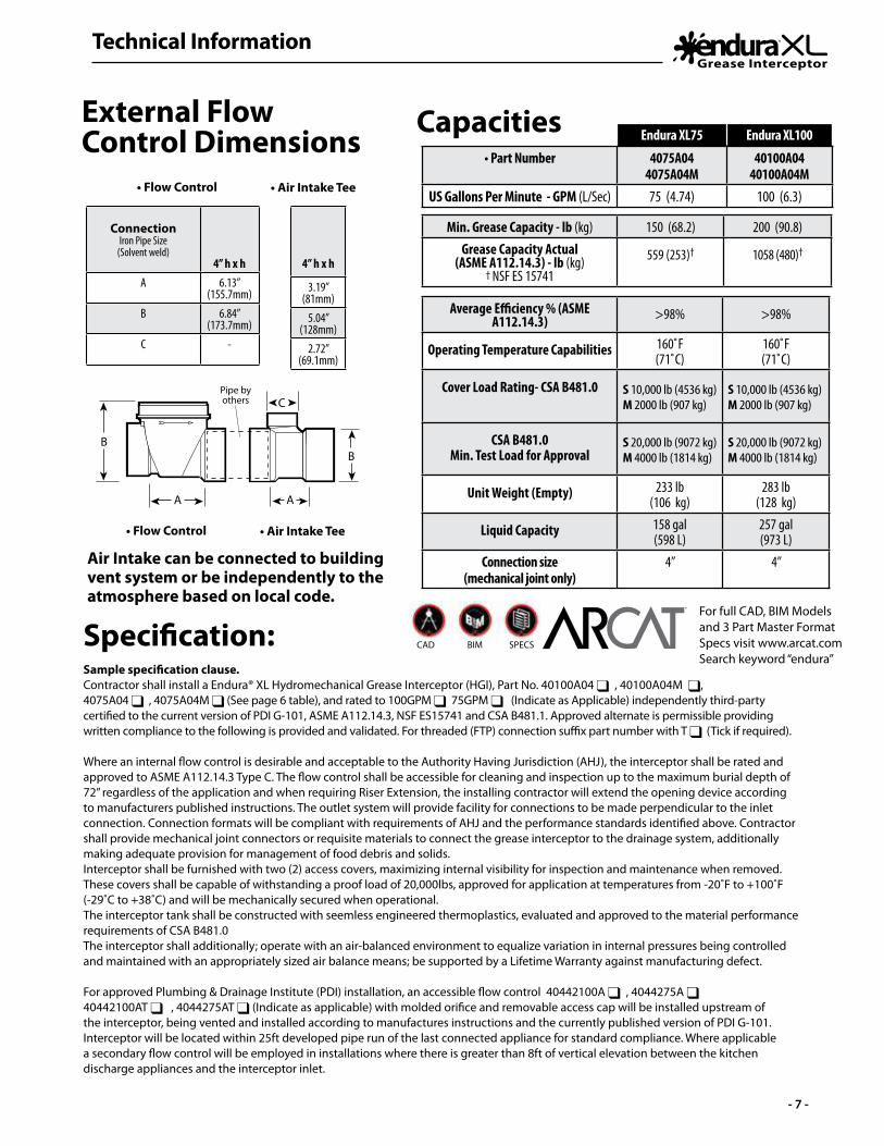
Air Intake can be connected to building vent system or be independently to the atmosphere based on local code.
• Flow Control
• Flow Control
Pipe by others
• Air Intake Tee
• Air Intake Tee
ConnectionIron Pipe Size
(Solvent weld)4” h x h
A 6.13”(155.7mm)
B 6.84”(173.7mm)
C -
4” h x h
3.19”(81mm)
5.04”(128mm)
2.72”(69.1mm)
CapacitiesExternal Flow Control Dimensions
For full CAD, BIM Models and 3 Part Master Format Specs visit www.arcat.comSearch keyword “endura”
CAD BIM SPECS
®
Endura XL75 Endura XL100
• Part Number 4075A044075A04M
40100A0440100A04M
US Gallons Per Minute - GPM (L/Sec) 75 (4.74) 100 (6.3)
Average Efficiency % (ASME A112.14.3) >98% >98%
Operating Temperature Capabilities 160˚F (71˚C)
160˚F (71˚C)
Cover Load Rating- CSA B481.0 S 10,000 lb (4536 kg)M 2000 lb (907 kg)
S 10,000 lb (4536 kg)M 2000 lb (907 kg)
CSA B481.0Min. Test Load for Approval
S 20,000 lb (9072 kg)M 4000 lb (1814 kg)
S 20,000 lb (9072 kg)M 4000 lb (1814 kg)
Unit Weight (Empty) 233 lb (106 kg)
283 lb (128 kg)
Liquid Capacity 158 gal (598 L)
257 gal (973 L)
Connection size (mechanical joint only)
4” 4”
Min. Grease Capacity - lb (kg) 150 (68.2) 200 (90.8)Grease Capacity Actual
(ASME A112.14.3) - lb (kg)† NSF ES 15741
559 (253)† 1058 (480)†
Installation Specifications
- 8 -
4"
the
unit
foot
prin
t
Con
cret
e P
ad
mus
t ext
end
18" o
utsi
de
45.0
0°
2 1/
2" M
in.
18" o
utsi
de th
e un
it fo
otpr
int
Con
cret
e P
ad m
ust e
xten
d
8"
4"
Top
Vie
w
Re
ba
r
Fin
ishe
d G
rad
eR
eb
ar
CO
NC
RET
E SL
AB
DET
AIL
FO
R T
RA
FFIC
LO
AD
ING
(INTE
RIO
R O
R E
XTER
IOR
)
Ele
vatio
n V
iew
(Con
nect
ing
pipe
and
fitti
ngs
by o
ther
s)Fo
r uni
t det
ails
see
spe
cific
atio
n sh
eet f
or s
elec
ted
unit
SID
E VI
EW D
ETA
IL
(INTE
RIO
R O
R E
XTER
IOR
)
EXC
AVA
TIO
N A
ND
B
AC
KFI
LL D
ETA
IL
DIM
ENSI
ON
S
72”
Max
imum
he
ight
Nat
ive
soil
Con
cret
e sl
ab
Crus
hed
aggr
egat
e m
ater
ial a
ppro
xim
atel
y 3/
4" si
ze ro
ck, p
ea g
rave
l or
sand
6” M
in. b
ase
crus
hed
aggr
egat
e m
ater
ial
appr
ox. 3
/4" s
ize
rock
,pe
a gr
avel
or s
and
95 p
roct
or.
unit
(by
othe
rs)
Cle
an o
ut to
gra
de
Flow
on o
utle
t pip
e of
eac
h
tee
(414
155B
C)
2-W
ay c
lean
out
tee
(414
155B
C)
2-W
ay c
lean
out
mec
hnic
al jo
int
coup
ling
(by
othe
rs)
Sta
ndar
d 4”
mec
hnic
al jo
ints
coup
ling
(by
othe
rs)
Sta
ndar
d 4”
on in
let p
ipe
of e
ach
Cle
an o
ut to
gra
de
unit
(by
othe
rs)
Flow
72”
Max
imum
he
ight
50”
26”
22”
14 29”
79”
32”
39.5
”
59”
43”
Ris
ers
to g
rade
MA
TL: P
E
DES
CR
IPTI
ON
:
DW
G B
Y: L
.S.
DW
G N
UM
BER
: XL7
5BG
T
4075
A04
407
5A04
T40
75A
04M
407
5A04
MT
End
ura
XL
grea
se in
terc
epto
rs a
re ra
ted
and
supp
lied
with
an
inte
rnal
flow
con
trol s
yste
m a
lread
y in
pla
ce.
They
do
not r
equi
re a
n ex
tern
al fl
ow c
ontro
l sys
tem
or a
ir in
take
ven
t unl
ess
spec
ified
by
loca
l cod
e re
quire
men
ts
or b
eing
ope
rate
d as
a P
DI G
-101
inst
alla
tion.
End
ura
XL
grea
se in
terc
epto
rs a
re o
nly
to b
e in
stal
led
in th
e m
anne
r and
for t
he a
pplic
atio
n sh
own.
Con
sult
loca
l cod
es fo
r sep
arat
e tra
ppin
g re
quire
men
ts, c
lean
out l
ocat
ions
an
d ad
ditio
nal i
nsta
llatio
n in
stru
ctio
ns. F
ull i
nstru
ctio
nal i
nfor
mat
ion
supp
lied
with
eve
ry in
terc
epto
r.
NO
TES:
PRO
PRIE
TAR
Y A
ND
CO
NFI
DEN
TIA
L - ©
Can
plas
201
7
Canp
las
Indu
stri
es L
td.
500
Vete
rans
Driv
e, B
ox 1
800
Barr
ie, O
ntar
io,
Cana
da L
4M 4
V3
CAN
: 1-8
00-4
61-1
771
USA
: 1-8
88-4
61-5
307
DA
TE: M
AY,
201
7 R
EV: 1
.2
Endu
ra b
rand
pro
duct
s m
anuf
actu
red
by
Canp
las
Indu
strie
s Lt
d.
Endu
ra® X
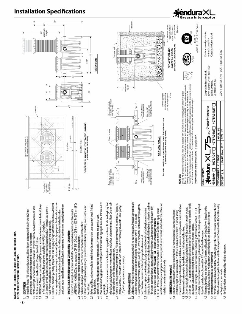
L - EX
TERI
OR BE
LOW
GRAD
E INS
TALL
ATIO
N IN
STRU
CTIO
NSBE
LOW
GRAD
E INS
TALL
ATIO
N IN
STRU
CTIO
NS
1.
EXCA
VATIO
N1.1
Ins
tall th
e End
ura ®
XL un
it(s)
as clo
se as
possi
ble to
fixtu
res be
ing se
rvice
d, ide
ally w
ithin
25ft o
f
deve
loped
pipe
run f
rom th
e las
t fixtu
re to
the i
nlet o
f the i
nterc
eptor
.1.2
Widt
h and
leng
th of
exca
vatio
n sha
ll be m
inim
um 12
” grea
ter th
an th
e tan
k dim
ensio
ns on
all si
des.
1.3 D
epth
of ex
cava
tion s
hall b
e at le
ast 6
” dee
per th
an ta
nk bo
ttom
. 1.4
IMP
ORTA
NT: M
axim
um bu
rial d
epth
6ft (7
2”) m
easu
red fro
m th
e air b
alanc
e cha
nnel
(Endu
raXL L
ogo)
to fin
ished
grad
e/flo
or lev
el. Ri
ser e
xtens
ions a
vaila
ble (4
0100
AX35
) - (s
ee be
low).
1.5 S
et th
e tan
k on w
ell-p
acke
d cru
shed
aggre
gate
mate
rial a
pprox
imate
ly 3/
4” siz
e roc
k, pe
a grav
el or
sand
. Whe
n sett
ing En
dura®
XL un
its th
ey m
ust b
e lev
el lat
erally
and l
ongit
udina
lly.
1.6 E
ndura
® XL t
anks
are s
pecifi
cally
desig
ned t
o res
ist bo
uyan
cy in
high
wate
r table
cond
itions
. Add
itiona
l
anch
oring
may
howe
ver b
e nec
essa
ry as
deter
mine
d by t
he sp
ecify
ing en
ginee
r. Tie-
down
loca
tions
are
inc
orpora
ted to
the t
ank a
nd ca
n be u
sed i
n con
juncti
on w
ith co
ated s
tainle
ss ste
el ca
ble an
d an
ap
plicab
le anc
hor m
ethod
based
on su
bsoil
. Spe
cific r
equir
emen
ts to b
e dete
rmine
d by s
pecif
ying e
ngine
er.
2.
BACK
FILLIN
G & FI
NISH
ED CO
NCRE
TE SL
AB (T
RAFF
IC LO
AD RA
TED)
En
dura®
XL is
supp
lied s
tand
ard w
ith tr
affic r
ated c
overs
desig
ned i
n acco
rdan
ce w
ith
AA
SHTO
304 –
H20 (
16,00
0lbs) a
nd ap
prove
d to C
SA B4
81.0
Class ‘
S’ -20
˚F to
+100
˚F (-2
9˚C to
+38
˚C)2.1
Prep
aratio
n of s
ub gr
ade p
er loc
al jur
isdict
ional
recom
men
datio
ns.
2.2 S
tabiliz
e and
com
pact
sub g
rade t
o 95%
proc
tor pe
r Exca
vatio
n info
rmati
on ab
ove.
2.3 F
ill tan
k with
wate
r (to d
ischa
rge le
vel) t
o prev
ent m
ovem
ent d
uring
back
filling
proc
ess a
nd to
resis
t
back
fill lo
ad.
2.4 B
efore
back
filling
and p
ourin
g of s
lab, in
stall r
iser(s
) (as n
eces
sary)
and c
over
asse
mbly
to su
it finis
hed
flo
or/gra
de le
vel.
2.5 B
ackfi
ll usin
g cru
shed
aggre
gate
mate
rial a
pprox
imate
ly 3/
4” siz
e roc
k, pe
a grav
el or
sand
. 2.6
Plac
e mini
mum
6” ag
grega
te ba
se be
neath
poure
d stru
ctural
slab.
Aggre
gate
shou
ld be
3/4”
size r
ock o
r
pea s
hingle
.2.7
Thic
knes
s of c
oncre
te aro
und c
over
to be
deter
mine
d by s
pecif
ying e
ngine
er. If
traffi
c load
ing is
requir
ed
ref
er to
local
spec
ifying
engin
eer re
com
men
datio
ns an
d/or
local
code
requ
irem
ents.
Note:
Conc
rete s
lab
dim
ensio
ns sh
own a
re for
illus
tratio
n pur
pose
s only
.2.8
Con
crete
to be
28 da
y com
pressi
ve st
rengt
h to 4
000 P
SI. Re
inforc
emen
t with
No.4
rebar
(1/2”
) grad
e 60
ste
el pe
r AST
M A6
15: co
nnec
ted w
ith tie
wire
. Reb
ar to
be 2½
” from
edge
of co
ncret
e. Re
bar s
pacin
g
12” g
rid. 4
” spa
cing a
round
acce
ss op
ening
s.
3.
PIPI
NG CO
NNEC
TIONS
3.1 A
ll End
ura® X
L Grea
se In
terce
ptors
are m
anufa
ctured
with
no hu
b con
necti
ons. T
hread
ed co
nnec
tions
are
av
ailab
le fro
m yo
ur En
dura
distri
butor
suffi
xing t
he pr
oduc
t cod
e with
‘T’ –
i.e. 4
0100
A04T
3.2 L
ocall
y app
roved
mec
hanic
al joi
nt (M
J) co
uplin
gs ar
e use
d to c
onne
ct th
e inle
t and
outle
t pipi
ng to
the
tan
k. Th
is allo
ws tra
nsitio
n to d
ifferen
t pipi
ng m
ateria
ls as r
equir
ed.
3.3 M
ake s
ystem
pipin
g con
necti
ons u
sing l
ocall
y app
roved
MJ c
oupli
ngs in
stallin
g to m
anufa
cturer
’s
instru
ction
s. Rev
iew al
l field
-mad
e con
necti
ons f
or lea
ks be
fore b
ackfi
lling b
egins
. Isola
te th
e tan
k from
the s
ystem
both
up an
d dow
n stre
am an
d fill t
ank w
ith w
ater, s
ubm
ersing
the i
nlet a
nd ou
tlet fu
lly
be
low th
e wate
r leve
l. DO N
OT PR
ESSU
RE TE
ST –
Risk
of se
rious
Inju
ry or
Deat
h.3.4
DO N
OT de
creas
e pipe
diam
eter a
cross
the u
nit (i.
e. 4 i
nch i
nlet, 3
inch
outle
t). If
the p
iping
syste
m
ne
eds t
o be r
esize
d, us
e app
ropria
te m
echa
nical
joint
redu
cers
cons
isten
t with
the d
irecti
on of
flow
and
ins
talled
in co
mpli
ance
with
loca
l code
.
4 EX
TENS
ION
RISE
RS (O
ption
al)4.1
End
ura® X
L Exte
nsion
Rise
rs pro
vide a
max
imum
of 35
” exte
nsion
per ri
ser.
Base
d on m
axim
um
ins
tallat
ion de
pth u
p to a
max
imum
of 72
” dep
th of
buria
l can a
chiev
ed (s
ee 1.
4 abo
ve), a
dding
Exten
sion R
isers
(or pa
rt th
ereof
) dur
ing in
stalla
tion.
Risers
are c
ut to
leng
th on
site t
o suit
insta
llatio
n.4.2
Rem
ove c
over
from
inter
cept
or. Se
t asid
e for
use a
t finis
hed g
rade/
floor
level.
4.3
Sec
ure ris
er to
tank (
fram
e rem
ains in
plac
e) us
ing fix
ings p
rovide
d. En
sure
seal
is corr
ectly
loca
ted.
4.4 S
ecure
the 1
-1/2
” ada
pter
fittin
g sup
plied
with
the E
xtens
ion Ki
t to th
e thre
ad on
the t
op of
the h
andle
mec
hanis
m. C
ut an
d exte
nd a
lengt
h of 1
½” DW
V pipe
per in
struc
tions
supp
lied.
4.5 F
or cu
stom
riser
lengt
h - m
easu
re fro
m ta
nk fra
me t
o finis
hed g
rade/
floor
level.
Subt
ract 1
½”. C
ut
cle
anly
by ha
nd or
mec
hanic
al m
eans
using
guide
rings
mold
ed in
to th
e rise
r to gi
ve cle
an st
raigh
t cut.
Note
- Hori
zont
al su
rface
of co
ver w
ill be
0.5”
abov
e finis
hed fl
oor/g
rade.
4.6 F
it rise
r sea
l prov
ided o
ver th
e cut
edge
of th
e rise
r and
loca
te fra
me (
supp
lied)
over
the s
eal m
aking
sure
it is f
ully s
eated
. Sec
ure w
ith la
g scre
ws pr
ovide
d usin
g the
pre-
drille
d loc
ation
s in fra
me.
4.7 R
epea
t proc
ess f
or ad
dition
al ris
er if/
as re
quire
d. 4.8
With
fram
e ins
talled
and v
erifie
d at th
e corr
ect h
eight,
pass
the h
andle
exten
sion s
uppo
rt ov
er th
e 1½”
DWV a
nd se
cure
the s
uppo
rt to
the f
rame w
ith th
e scre
w pro
vided
. Solv
ent w
eld a
1½” v
ent te
e on t
op
of
the p
ipe to
act a
s a ha
ndle.
4.9 R
e-fit
the o
rigina
l cove
r(s) p
rovide
d with
the i
nterc
eptor
.

Installation Specifications
- 9 -
Endu
ra® X
L - EX
TERI
OR BE
LOW
GRAD
E INS
TALL
ATIO
N IN
STRU
CTIO
NSBE
LOW
GRAD
E INS
TALL
ATIO
N IN
STRU
CTIO
NS
1.
EXCA
VATIO
N1.1
Ins
tall th
e End
ura ®
XL un
it(s)
as clo
se as
possi
ble to
fixtu
res be
ing se
rvice
d, ide
ally w
ithin
25ft o
f
deve
loped
pipe
run f
rom th
e las
t fixtu
re to
the i
nlet o
f the i
nterc
eptor
.1.2
Widt
h and
leng
th of
exca
vatio
n sha
ll be m
inim
um 12
” grea
ter th
an th
e tan
k dim
ensio
ns on
all si
des.
1.3 D
epth
of ex
cava
tion s
hall b
e at le
ast 6
” dee
per th
an ta
nk bo
ttom
. 1.4
IMP
ORTA
NT: M
axim
um bu
rial d
epth
6ft (7
2”) m
easu
red fro
m th
e air b
alanc
e cha
nnel
(Endu
raXL L
ogo)
to fin
ished
grad
e/flo
or lev
el. Ri
ser e
xtens
ions a
vaila
ble (4
0100
AX35
) - (s
ee be
low).
1.5 S
et th
e tan
k on w
ell-p
acke
d cru
shed
aggre
gate
mate
rial a
pprox
imate
ly 3/
4” siz
e roc
k, pe
a grav
el or
sand
. Whe
n sett
ing En
dura®
XL un
its th
ey m
ust b
e lev
el lat
erally
and l
ongit
udina
lly.
1.6 E
ndura
® XL t
anks
are s
pecifi
cally
desig
ned t
o res
ist bo
uyan
cy in
high
wate
r table
cond
itions
. Add
itiona
l
anch
oring
may
howe
ver b
e nec
essa
ry as
deter
mine
d by t
he sp
ecify
ing en
ginee
r. Tie-
down
loca
tions
are
inc
orpora
ted to
the t
ank a
nd ca
n be u
sed i
n con
juncti
on w
ith co
ated s
tainle
ss ste
el ca
ble an
d an
ap
plicab
le anc
hor m
ethod
based
on su
bsoil
. Spe
cific r
equir
emen
ts to b
e dete
rmine
d by s
pecif
ying e
ngine
er.
2.
BACK
FILLIN
G & FI
NISH
ED CO
NCRE
TE SL
AB (T
RAFF
IC LO
AD RA
TED)
En
dura®
XL is
supp
lied s
tand
ard w
ith tr
affic r
ated c
overs
desig
ned i
n acco
rdan
ce w
ith
AA
SHTO
304 –
H20 (
16,00
0lbs) a
nd ap
prove
d to C
SA B4
81.0
Class ‘
S’ -20
˚F to
+100
˚F (-2
9˚C to
+38
˚C)2.1
Prep
aratio
n of s
ub gr
ade p
er loc
al jur
isdict
ional
recom
men
datio
ns.
2.2 S
tabiliz
e and
com
pact
sub g
rade t
o 95%
proc
tor pe
r Exca
vatio
n info
rmati
on ab
ove.
2.3 F
ill tan
k with
wate
r (to d
ischa
rge le
vel) t
o prev
ent m
ovem
ent d
uring
back
filling
proc
ess a
nd to
resis
t
back
fill lo
ad.
2.4 B
efore
back
filling
and p
ourin
g of s
lab, in
stall r
iser(s
) (as n
eces
sary)
and c
over
asse
mbly
to su
it finis
hed
flo
or/gra
de le
vel.
2.5 B
ackfi
ll usin
g cru
shed
aggre
gate
mate
rial a
pprox
imate
ly 3/
4” siz
e roc
k, pe
a grav
el or
sand
. 2.6
Plac
e mini
mum
6” ag
grega
te ba
se be
neath
poure
d stru
ctural
slab.
Aggre
gate
shou
ld be
3/4”
size r
ock o
r
pea s
hingle
.2.7
Thic
knes
s of c
oncre
te aro
und c
over
to be
deter
mine
d by s
pecif
ying e
ngine
er. If
traffi
c load
ing is
requir
ed
ref
er to
local
spec
ifying
engin
eer re
com
men
datio
ns an
d/or
local
code
requ
irem
ents.
Note:
Conc
rete s
lab
dim
ensio
ns sh
own a
re for
illus
tratio
n pur
pose
s only
.2.8
Con
crete
to be
28 da
y com
pressi
ve st
rengt
h to 4
000 P
SI. Re
inforc
emen
t with
No.4
rebar
(1/2”
) grad
e 60
ste
el pe
r AST
M A6
15: co
nnec
ted w
ith tie
wire
. Reb
ar to
be 2½
” from
edge
of co
ncret
e. Re
bar s
pacin
g
12” g
rid. 4
” spa
cing a
round
acce
ss op
ening
s.
3.
PIPI
NG CO
NNEC
TIONS
3.1 A
ll End
ura® X
L Grea
se In
terce
ptors
are m
anufa
ctured
with
no hu
b con
necti
ons. T
hread
ed co
nnec
tions
are
av
ailab
le fro
m yo
ur En
dura
distri
butor
suffi
xing t
he pr
oduc
t cod
e with
‘T’ –
i.e. 4
0100
A04T
3.2 L
ocall
y app
roved
mec
hanic
al joi
nt (M
J) co
uplin
gs ar
e use
d to c
onne
ct th
e inle
t and
outle
t pipi
ng to
the
tan
k. Th
is allo
ws tra
nsitio
n to d
ifferen
t pipi
ng m
ateria
ls as r
equir
ed.
3.3 M
ake s
ystem
pipin
g con
necti
ons u
sing l
ocall
y app
roved
MJ c
oupli
ngs in
stallin
g to m
anufa
cturer
’s
instru
ction
s. Rev
iew al
l field
-mad
e con
necti
ons f
or lea
ks be
fore b
ackfi
lling b
egins
. Isola
te th
e tan
k from
the s
ystem
both
up an
d dow
n stre
am an
d fill t
ank w
ith w
ater, s
ubm
ersing
the i
nlet a
nd ou
tlet fu
lly
be
low th
e wate
r leve
l. DO N
OT PR
ESSU
RE TE
ST –
Risk
of se
rious
Inju
ry or
Deat
h.3.4
DO N
OT de
creas
e pipe
diam
eter a
cross
the u
nit (i.
e. 4 i
nch i
nlet, 3
inch
outle
t). If
the p
iping
syste
m
ne
eds t
o be r
esize
d, us
e app
ropria
te m
echa
nical
joint
redu
cers
cons
isten
t with
the d
irecti
on of
flow
and
ins
talled
in co
mpli
ance
with
loca
l code
.
4 EX
TENS
ION
RISE
RS (O
ption
al)4.1
End
ura® X
L Exte
nsion
Rise
rs pro
vide a
max
imum
of 35
” exte
nsion
per ri
ser.
Base
d on m
axim
um
ins
tallat
ion de
pth u
p to a
max
imum
of 72
” dep
th of
buria
l can a
chiev
ed (s
ee 1.
4 abo
ve), a
dding
Exten
sion R
isers
(or pa
rt th
ereof
) dur
ing in
stalla
tion.
Risers
are c
ut to
leng
th on
site t
o suit
insta
llatio
n.4.2
Rem
ove c
over
from
inter
cept
or. Se
t asid
e for
use a
t finis
hed g
rade/
floor
level.
4.3
Sec
ure ris
er to
tank (
fram
e rem
ains in
plac
e) us
ing fix
ings p
rovide
d. En
sure
seal
is corr
ectly
loca
ted.
4.4 S
ecure
the 1
-1/2
” ada
pter
fittin
g sup
plied
with
the E
xtens
ion Ki
t to th
e thre
ad on
the t
op of
the h
andle
mec
hanis
m. C
ut an
d exte
nd a
lengt
h of 1
½” DW
V pipe
per in
struc
tions
supp
lied.
4.5 F
or cu
stom
riser
lengt
h - m
easu
re fro
m ta
nk fra
me t
o finis
hed g
rade/
floor
level.
Subt
ract 1
½”. C
ut
cle
anly
by ha
nd or
mec
hanic
al m
eans
using
guide
rings
mold
ed in
to th
e rise
r to gi
ve cle
an st
raigh
t cut.
Note
- Hori
zont
al su
rface
of co
ver w
ill be
0.5”
abov
e finis
hed fl
oor/g
rade.
4.6 F
it rise
r sea
l prov
ided o
ver th
e cut
edge
of th
e rise
r and
loca
te fra
me (
supp
lied)
over
the s
eal m
aking
sure
it is f
ully s
eated
. Sec
ure w
ith la
g scre
ws pr
ovide
d usin
g the
pre-
drille
d loc
ation
s in fra
me.
4.7 R
epea
t proc
ess f
or ad
dition
al ris
er if/
as re
quire
d. 4.8
With
fram
e ins
talled
and v
erifie
d at th
e corr
ect h
eight,
pass
the h
andle
exten
sion s
uppo
rt ov
er th
e 1½”
DWV a
nd se
cure
the s
uppo
rt to
the f
rame w
ith th
e scre
w pro
vided
. Solv
ent w
eld a
1½” v
ent te
e on t
op
of
the p
ipe to
act a
s a ha
ndle.
4.9 R
e-fit
the o
rigina
l cove
r(s) p
rovide
d with
the i
nterc
eptor
.
End
ura
XL
grea
se in
terc
epto
rs a
re ra
ted
and
supp
lied
with
an
inte
rnal
flow
con
trol s
yste
m a
lread
y in
pla
ce.
They
do
not r
equi
re a
n ex
tern
al fl
ow c
ontro
l sys
tem
or a
ir in
take
ven
t unl
ess
spec
ified
by
loca
l cod
e re
quire
men
ts
or b
eing
ope
rate
d as
a P
DI G
-101
inst
alla
tion.
End
ura
XL
grea
se in
terc
epto
rs a
re o
nly
to b
e in
stal
led
in th
e m
anne
r and
for t
he a
pplic
atio
n sh
own.
Con
sult
loca
l cod
es fo
r sep
arat
e tra
ppin
g re
quire
men
ts, c
lean
out l
ocat
ions
an
d ad
ditio
nal i
nsta
llatio
n in
stru
ctio
ns. F
ull i
nstru
ctio
nal i
nfor
mat
ion
supp
lied
with
eve
ry in
terc
epto
r.
NO
TES:
PRO
PRIE
TAR
Y A
ND
CO
NFI
DEN
TIA
L - ©
Can
plas
201
7
4"
the
unit
foot
prin
t
Con
cret
e P
ad
mus
t ext
end
18" o
utsi
de
45.0
0°
2 1/
2" M
in.
18" o
utsi
de th
e un
it fo
otpr
int
Con
cret
e P
ad m
ust e
xten
d
8"
4"
Top
Vie
w
Re
ba
r
Fin
ishe
d G
rad
eR
eb
ar
CO
NC
RET
E SL
AB
DET
AIL
FO
R T
RA
FFIC
LO
AD
ING
(INTE
RIO
R O
R E
XTER
IOR
)
Ele
vatio
n V
iew
(Con
nect
ing
pipe
and
fitti
ngs
by o
ther
s)Fo
r uni
t det
ails
see
spe
cific
atio
n sh
eet f
or s
elec
ted
unit
SID
E VI
EW D
ETA
IL
DIM
ENSI
ON
S
26”
22”
14”
34.5
”
48.5
”
84.5
”
50”
72”
Max
imum
he
ight
72”
Max
imum
he
ight
78”
48.5
”
32”
Nat
ive
soil
Con
cret
e sl
ab
Crus
hed
aggr
egat
e m
ater
ial a
ppro
xim
atel
y 3/
4" si
ze ro
ck, p
ea g
rave
l or
sand
unit
(by
othe
rs)
Cle
an o
ut to
gra
de
Flow
on o
utle
t pip
e of
eac
h
tee
(414
155B
C)
2-W
ay c
lean
out
tee
(414
155B
C)
2-W
ay c
lean
out
mec
hnic
al jo
int
coup
ling
(by
othe
rs)
Sta
ndar
d 4”
mec
hnic
al jo
ints
coup
ling
(by
othe
rs)
Sta
ndar
d 4”
on in
let p
ipe
of e
ach
Cle
an o
ut to
gra
de
unit
(by
othe
rs)
Flow
Ris
ers
to g
rade
DA
TE: M
AY,
201
7 R
EV: 1
.2M
ATL
: PE
DES
CR
IPTI
ON
:
DW
G B
Y: L
.S.
DW
G N
UM
BER
: XL1
00B
GT
6” M
in. b
ase
crus
hed
aggr
egat
e m
ater
ial
appr
ox. 3
/4" s
ize
rock
,pe
a gr
avel
or s
and
95 p
roct
or.
(INTE
RIO
R O
R E
XTER
IOR
)
EXC
AVA
TIO
N A
ND
B
AC
KFI
LL D
ETA
IL
Canp
las
Indu
stri
es L
td.
500
Vete
rans
Driv
e, B
ox 1
800
Barr
ie, O
ntar
io,
Cana
da L
4M 4
V3
CAN
: 1-8
00-4
61-1
771
USA
: 1-8
88-4
61-5
307
Endu
ra b
rand
pro
duct
s m
anuf
actu
red
by
Canp
las
Indu
strie
s Lt
d.40
100A
04
40
100A
04M
4010
0A04
T
401
00A
04M
T
Endu
ra® X
L - EX
TERI
OR BE
LOW
GRAD
E INS
TALL
ATIO
N IN
STRU
CTIO
NSBE
LOW
GRAD
E INS
TALL
ATIO
N IN
STRU
CTIO
NS
1.
EXCA
VATIO
N1.1
Ins
tall th
e End
ura ®
XL un
it(s)
as clo
se as
possi
ble to
fixtu
res be
ing se
rvice
d, ide
ally w
ithin
25ft o
f
deve
loped
pipe
run f
rom th
e las
t fixtu
re to
the i
nlet o
f the i
nterc
eptor
.1.2
Widt
h and
leng
th of
exca
vatio
n sha
ll be m
inim
um 12
” grea
ter th
an th
e tan
k dim
ensio
ns on
all si
des.
1.3 D
epth
of ex
cava
tion s
hall b
e at le
ast 6
” dee
per th
an ta
nk bo
ttom
. 1.4
IMP
ORTA
NT: M
axim
um bu
rial d
epth
6ft (7
2”) m
easu
red fro
m th
e air b
alanc
e cha
nnel
(Endu
raXL L
ogo)
to fin
ished
grad
e/flo
or lev
el. Ri
ser e
xtens
ions a
vaila
ble (4
0100
AX35
) - (s
ee be
low).
1.5 S
et th
e tan
k on w
ell-p
acke
d cru
shed
aggre
gate
mate
rial a
pprox
imate
ly 3/
4” siz
e roc
k, pe
a grav
el or
sand
. Whe
n sett
ing En
dura®
XL un
its th
ey m
ust b
e lev
el lat
erally
and l
ongit
udina
lly.
1.6 E
ndura
® XL t
anks
are s
pecifi
cally
desig
ned t
o res
ist bo
uyan
cy in
high
wate
r table
cond
itions
. Add
itiona
l
anch
oring
may
howe
ver b
e nec
essa
ry as
deter
mine
d by t
he sp
ecify
ing en
ginee
r. Tie-
down
loca
tions
are
inc
orpora
ted to
the t
ank a
nd ca
n be u
sed i
n con
juncti
on w
ith co
ated s
tainle
ss ste
el ca
ble an
d an
ap
plicab
le anc
hor m
ethod
based
on su
bsoil
. Spe
cific r
equir
emen
ts to b
e dete
rmine
d by s
pecif
ying e
ngine
er.
2.
BACK
FILLIN
G & FI
NISH
ED CO
NCRE
TE SL
AB (T
RAFF
IC LO
AD RA
TED)
En
dura®
XL is
supp
lied s
tand
ard w
ith tr
affic r
ated c
overs
desig
ned i
n acco
rdan
ce w
ith
AA
SHTO
304 –
H20 (
16,00
0lbs) a
nd ap
prove
d to C
SA B4
81.0
Class ‘
S’ -20
˚F to
+100
˚F (-2
9˚C to
+38
˚C)2.1
Prep
aratio
n of s
ub gr
ade p
er loc
al jur
isdict
ional
recom
men
datio
ns.
2.2 S
tabiliz
e and
com
pact
sub g
rade t
o 95%
proc
tor pe
r Exca
vatio
n info
rmati
on ab
ove.
2.3 F
ill tan
k with
wate
r (to d
ischa
rge le
vel) t
o prev
ent m
ovem
ent d
uring
back
filling
proc
ess a
nd to
resis
t
back
fill lo
ad.
2.4 B
efore
back
filling
and p
ourin
g of s
lab, in
stall r
iser(s
) (as n
eces
sary)
and c
over
asse
mbly
to su
it finis
hed
flo
or/gra
de le
vel.
2.5 B
ackfi
ll usin
g cru
shed
aggre
gate
mate
rial a
pprox
imate
ly 3/
4” siz
e roc
k, pe
a grav
el or
sand
. 2.6
Plac
e mini
mum
6” ag
grega
te ba
se be
neath
poure
d stru
ctural
slab.
Aggre
gate
shou
ld be
3/4”
size r
ock o
r
pea s
hingle
.2.7
Thic
knes
s of c
oncre
te aro
und c
over
to be
deter
mine
d by s
pecif
ying e
ngine
er. If
traffi
c load
ing is
requir
ed
ref
er to
local
spec
ifying
engin
eer re
com
men
datio
ns an
d/or
local
code
requ
irem
ents.
Note:
Conc
rete s
lab
dim
ensio
ns sh
own a
re for
illus
tratio
n pur
pose
s only
.2.8
Con
crete
to be
28 da
y com
pressi
ve st
rengt
h to 4
000 P
SI. Re
inforc
emen
t with
No.4
rebar
(1/2”
) grad
e 60
ste
el pe
r AST
M A6
15: co
nnec
ted w
ith tie
wire
. Reb
ar to
be 2½
” from
edge
of co
ncret
e. Re
bar s
pacin
g
12” g
rid. 4
” spa
cing a
round
acce
ss op
ening
s.
3.
PIPI
NG CO
NNEC
TIONS
3.1 A
ll End
ura® X
L Grea
se In
terce
ptors
are m
anufa
ctured
with
no hu
b con
necti
ons. T
hread
ed co
nnec
tions
are
av
ailab
le fro
m yo
ur En
dura
distri
butor
suffi
xing t
he pr
oduc
t cod
e with
‘T’ –
i.e. 4
0100
A04T
3.2 L
ocall
y app
roved
mec
hanic
al joi
nt (M
J) co
uplin
gs ar
e use
d to c
onne
ct th
e inle
t and
outle
t pipi
ng to
the
tan
k. Th
is allo
ws tra
nsitio
n to d
ifferen
t pipi
ng m
ateria
ls as r
equir
ed.
3.3 M
ake s
ystem
pipin
g con
necti
ons u
sing l
ocall
y app
roved
MJ c
oupli
ngs in
stallin
g to m
anufa
cturer
’s
instru
ction
s. Rev
iew al
l field
-mad
e con
necti
ons f
or lea
ks be
fore b
ackfi
lling b
egins
. Isola
te th
e tan
k from
the s
ystem
both
up an
d dow
n stre
am an
d fill t
ank w
ith w
ater, s
ubm
ersing
the i
nlet a
nd ou
tlet fu
lly
be
low th
e wate
r leve
l. DO N
OT PR
ESSU
RE TE
ST –
Risk
of se
rious
Inju
ry or
Deat
h.3.4
DO N
OT de
creas
e pipe
diam
eter a
cross
the u
nit (i.
e. 4 i
nch i
nlet, 3
inch
outle
t). If
the p
iping
syste
m
ne
eds t
o be r
esize
d, us
e app
ropria
te m
echa
nical
joint
redu
cers
cons
isten
t with
the d
irecti
on of
flow
and
ins
talled
in co
mpli
ance
with
loca
l code
.
4 EX
TENS
ION
RISE
RS (O
ption
al)4.1
End
ura® X
L Exte
nsion
Rise
rs pro
vide a
max
imum
of 35
” exte
nsion
per ri
ser.
Base
d on m
axim
um
ins
tallat
ion de
pth u
p to a
max
imum
of 72
” dep
th of
buria
l can a
chiev
ed (s
ee 1.
4 abo
ve), a
dding
Exten
sion R
isers
(or pa
rt th
ereof
) dur
ing in
stalla
tion.
Risers
are c
ut to
leng
th on
site t
o suit
insta
llatio
n.4.2
Rem
ove c
over
from
inter
cept
or. Se
t asid
e for
use a
t finis
hed g
rade/
floor
level.
4.3
Sec
ure ris
er to
tank (
fram
e rem
ains in
plac
e) us
ing fix
ings p
rovide
d. En
sure
seal
is corr
ectly
loca
ted.
4.4 S
ecure
the 1
-1/2
” ada
pter
fittin
g sup
plied
with
the E
xtens
ion Ki
t to th
e thre
ad on
the t
op of
the h
andle
mec
hanis
m. C
ut an
d exte
nd a
lengt
h of 1
½” DW
V pipe
per in
struc
tions
supp
lied.
4.5 F
or cu
stom
riser
lengt
h - m
easu
re fro
m ta
nk fra
me t
o finis
hed g
rade/
floor
level.
Subt
ract 1
½”. C
ut
cle
anly
by ha
nd or
mec
hanic
al m
eans
using
guide
rings
mold
ed in
to th
e rise
r to gi
ve cle
an st
raigh
t cut.
Note
- Hori
zont
al su
rface
of co
ver w
ill be
0.5”
abov
e finis
hed fl
oor/g
rade.
4.6 F
it rise
r sea
l prov
ided o
ver th
e cut
edge
of th
e rise
r and
loca
te fra
me (
supp
lied)
over
the s
eal m
aking
sure
it is f
ully s
eated
. Sec
ure w
ith la
g scre
ws pr
ovide
d usin
g the
pre-
drille
d loc
ation
s in fra
me.
4.7 R
epea
t proc
ess f
or ad
dition
al ris
er if/
as re
quire
d. 4.8
With
fram
e ins
talled
and v
erifie
d at th
e corr
ect h
eight,
pass
the h
andle
exten
sion s
uppo
rt ov
er th
e 1½”
DWV a
nd se
cure
the s
uppo
rt to
the f
rame w
ith th
e scre
w pro
vided
. Solv
ent w
eld a
1½” v
ent te
e on t
op
of
the p
ipe to
act a
s a ha
ndle.
4.9 R
e-fit
the o
rigina
l cove
r(s) p
rovide
d with
the i
nterc
eptor
.
Installation Specifications
- 10 -
Exte
rnal
Fl
ow C
ontro
lIf
Requ
ired
Exte
rnal
Fl
ow C
ontro
lIf
Requ
ired
Exte
rnal
Fl
ow C
ontro
lIf
Requ
ired
Exte
rnal
Fl
ow C
ontro
lIf
Requ
ired
Exte
rnal
Fl
ow C
ontro
lIf
Requ
ired
OU
T
OU
TO
UT
OU
T
GREASE INTERCEPTOR
GREASE INTERCEPTOR
GREASE INTERCEPTOR
GREASE INTERCEPTOR
OU
T
GREASE INTERCEPTOR
GREASE INTERCEPTOR
GREASE INTERCEPTOR
GREASE INTERCEPTOR
GR
EASE
IN
TER
CEP
TORG
REA
SE INT
ERC
EPTO
RGR
EASE
IN
TER
CEP
TORG
REA
SE INT
ERC
EPTO
R
GR
EASE
IN
TER
CEP
TORG
REA
SE INT
ERC
EPTO
RGR
EASE
IN
TER
CEP
TORG
REA
SE INT
ERC
EPTO
R
GR
EASE
IN
TER
CEP
TORG
REA
SE INT
ERC
EPTO
RGR
EASE
IN
TER
CEP
TORG
REA
SE INT
ERC
EPTO
R
GR
EASE
IN
TER
CEP
TORG
REA
SE INT
ERC
EPTO
RGR
EASE
IN
TER
CEP
TORG
REA
SE INT
ERC
EPTO
R
OU
T
OU
T
IN
IN
GR
EASE
IN
TER
CEP
TORG
REA
SE INT
ERC
EPTO
RGR
EASE
IN
TER
CEP
TORG
REA
SE INT
ERC
EPTO
RG
REA
SE INT
ERC
EPTO
R GR
EASE
IN
TER
CEP
TOR G
REA
SE INT
ERC
EPTO
R GR
EASE
IN
TER
CEP
TOR
IN
IN
IN
IN
GR
EASE
IN
TER
CEP
TORG
REA
SE INT
ERC
EPTO
RGR
EASE
IN
TER
CEP
TORG
REA
SE INT
ERC
EPTO
RG
REA
SE INT
ERC
EPTO
R GR
EASE
IN
TER
CEP
TOR G
REA
SE INT
ERC
EPTO
R GR
EASE
IN
TER
CEP
TOR
GREASE INTERCEPTOR
GREASE INTERCEPTOR
GREASE INTERCEPTOR
GREASE INTERCEPTOR
OU
TIN
GREASE INTERCEPTOR
GREASE INTERCEPTOR
GREASE INTERCEPTOR
GREASE INTERCEPTOR
GREASE INTERCEPTOR
GREASE INTERCEPTOR
GREASE INTERCEPTOR
GREASE INTERCEPTOR
IN
GREASE INTERCEPTOR
GREASE INTERCEPTOR
GREASE INTERCEPTOR
GREASE INTERCEPTOR
GREASE INTERCEPTOR
GREASE INTERCEPTOR
GREASE INTERCEPTOR
GREASE INTERCEPTOR
OU
T
GREASE INTERCEPTOR
GREASE INTERCEPTOR
GREASE INTERCEPTOR
GREASE INTERCEPTOR
GREASE INTERCEPTOR
GREASE INTERCEPTORGREASE INTERCEPTOR
GREASE INTERCEPTOR
IN
GR
EASE
IN
TER
CEP
TORG
REA
SE INT
ERC
EPTO
RGR
EASE
IN
TER
CEP
TORG
REA
SE INT
ERC
EPTO
R
GR
EASE
IN
TER
CEP
TORG
REA
SE INT
ERC
EPTO
RGR
EASE
IN
TER
CEP
TORG
REA
SE INT
ERC
EPTO
R
GR
EASE
IN
TER
CEP
TORG
REA
SE INT
ERC
EPTO
RGR
EASE
IN
TER
CEP
TORG
REA
SE INT
ERC
EPTO
R
OU
T
IN
GREASE INTERCEPTOR
GREASE INTERCEPTOR
GREASE INTERCEPTOR
GREASE INTERCEPTOR
GREASE INTERCEPTOR
GREASE INTERCEPTOR
GREASE INTERCEPTOR
GREASE INTERCEPTOR
OU
TIN
GR
E ASE
IN
TE R
CE P
TORG
REA
SE INT
ERC
EPTO
RGR
EASE
IN
TER
CE P
TORG
REA
SE INT
ERC
EPTO
R
GR
E ASE
IN
TE R
CEP
TORG
REA
SE INT
ERC
EPTO
RGR
EASE
IN
TER
CEP
TORG
REA
SE INT
ERC
EPTO
R
GR
EASE
IN
TER
CEP
TORG
REA
SE INT
ERC
EPTO
RGR
EASE
IN
TER
CEP
TORG
REA
SE INT
ERC
EPTO
R
GR
EASE
IN
TER
CE P
TORG
REA
SE INT
ERC
EPTO
RGR
E ASE
IN
TE R
CEP
TORG
REA
SE INT
ERC
EPTO
R
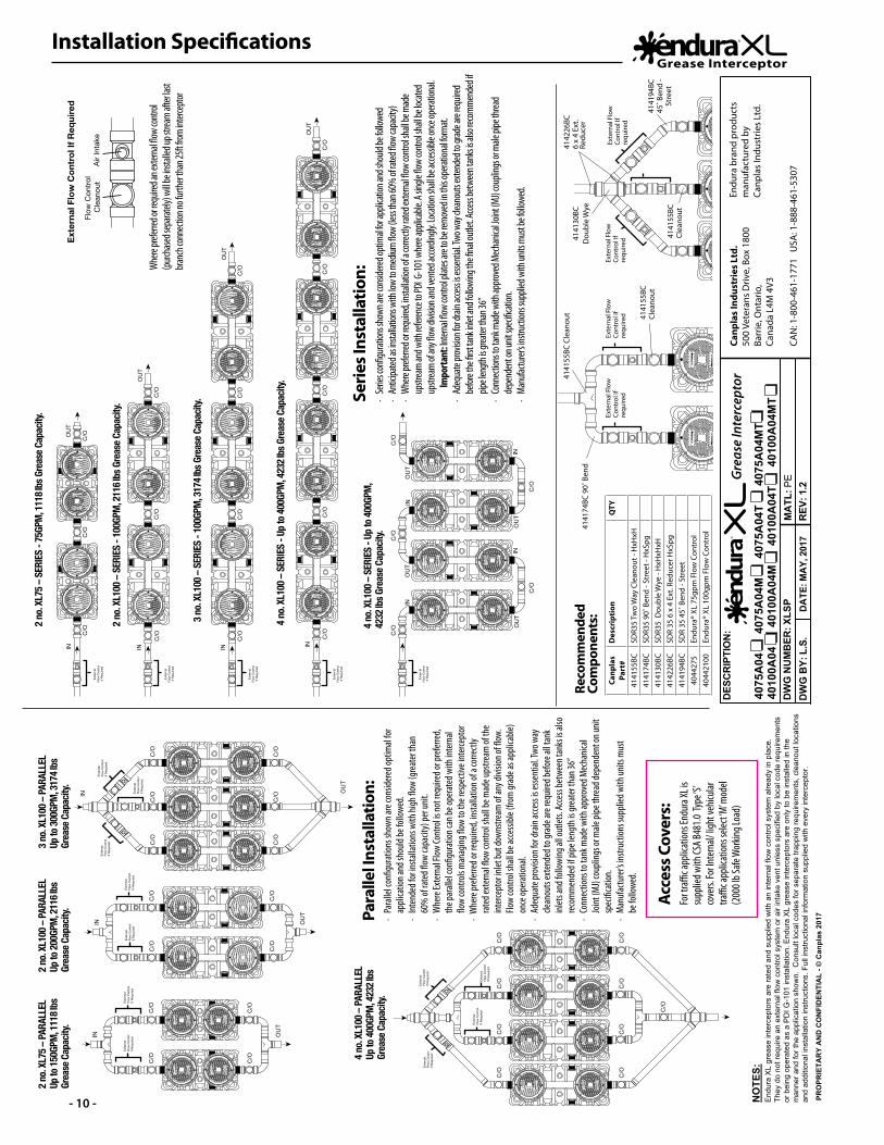
4075
A04
4075
A04
M
40
75A
04T
4
075A
04M
T
MA
TL: P
E
DES
CR
IPTI
ON
:
DW
G B
Y: L
.S.
DW
G N
UM
BER
: XLS
P40
100A
04
40
100A
04M
4010
0A04
T
401
00A
04M
T
C/O
C/O
C/O
C/O
C/O
C/O
C/O
C/O
C/O
C/O
C/O
C/O
C/OC
/O
C/O
C/O
C/O
C/O
C/O
C/O
C/O
C/O
C/O
C/O
C/O
C/O
C/O
C/O
C/O
C/O
C/O
C/O
Exte
rnal
Fl
ow C
ontro
lIf
Requ
ired
Exte
rnal
Fl
ow C
ontro
lIf
Requ
ired
Exte
rnal
Fl
ow C
ontro
lIf
Requ
ired
Exte
rnal
Flo
w C
ontr
ol If
Req
uire
d
Flow
Con
trol
Cle
anou
tAi
r Int
ake
Exte
rnal
Fl
ow C
ontro
lIf
Requ
ired
C/O
C/O
C/O
C/O
C/O
C/O
C/O
C/O
C/O
C/O
C/O
Exte
rnal
Fl
ow C
ontro
lIf
Requ
ired
Exte
rnal
Fl
ow C
ontro
lIf
Requ
ired
Exte
rnal
Fl
ow C
ontro
lIf
Requ
ired
Exte
rnal
Fl
ow C
ontro
lIf
Requ
ired
Exte
rnal
Fl
ow C
ontro
lIf
Requ
ired
Exte
rnal
Fl
ow C
ontro
lIf
Requ
ired
Exte
rnal
Fl
ow C
ontro
lIf
Requ
ired
GR
EASE
INT
ERC
EPTO
RGR
EASE IN
TER
CEP
TOR
GR
EASE
INT
ERC
EPTO
RGR
EASE IN
TER
CEP
TOR
End
ura
XL
grea
se in
terc
epto
rs a
re ra
ted
and
supp
lied
with
an
inte
rnal
flow
con
trol s
yste
m a
lread
y in
pla
ce.
They
do
not r
equi
re a
n ex
tern
al fl
ow c
ontro
l sys
tem
or a
ir in
take
ven
t unl
ess
spec
ified
by
loca
l cod
e re
quire
men
ts
or b
eing
ope
rate
d as
a P
DI G
-101
inst
alla
tion.
End
ura
XL
grea
se in
terc
epto
rs a
re o
nly
to b
e in
stal
led
in th
e m
anne
r and
for t
he a
pplic
atio
n sh
own.
Con
sult
loca
l cod
es fo
r sep
arat
e tra
ppin
g re
quire
men
ts, c
lean
out l
ocat
ions
an
d ad
ditio
nal i
nsta
llatio
n in
stru
ctio
ns. F
ull i
nstru
ctio
nal i
nfor
mat
ion
supp
lied
with
eve
ry in
terc
epto
r.
NO
TES:
PRO
PRIE
TAR
Y A
ND
CO
NFI
DEN
TIA
L - ©
Can
plas
201
7
DA
TE: M
AY,
201
7 R
EV: 1
.2
Canp
las
Indu
stri
es L
td.
500
Vete
rans
Driv
e, B
ox 1
800
Barr
ie, O
ntar
io,
Cana
da L
4M 4
V3
CAN
: 1-8
00-4
61-1
771
USA
: 1-8
88-4
61-5
307
Endu
ra b
rand
pro
duct
s m
anuf
actu
red
by
Canp
las
Indu
strie
s Lt
d.
Serie
s Ins
talla
tion:
· Se
ries c
onfig
uratio
ns sh
own a
re co
nside
red op
timal
for ap
plica
tion a
nd sh
ould
be fo
llowe
d·
Antic
ipated
as in
stalla
tions
with
low
to m
edium
flow
(less
than
60%
of ra
ted flo
w ca
pacit
y)·
Whe
re pre
ferred
or re
quire
d, ins
tallat
ion of
a co
rrectl
y rate
d exte
rnal
flow
cont
rol sh
all be
mad
e
upstr
eam
and w
ith re
feren
ce to
PDI G
-101
whe
re ap
plica
ble. A
single
flow
cont
rol sh
all be
loca
ted
up
strea
m of
any fl
ow di
vision
and v
ented
acco
rding
ly. Lo
catio
n sha
ll be a
ccessi
ble on
ce op
eratio
nal.
I
mpo
rtant
: Inter
nal fl
ow co
ntrol
plate
s are
to be
rem
oved
in th
is ope
ration
al for
mat.
· Ad
equa
te pro
vision
for d
rain a
ccess
is esse
ntial
. Two w
ay cle
anou
ts ex
tende
d to g
rade a
re req
uired
befor
e the
first
tank i
nlet a
nd fo
llowi
ng th
e fina
l out
let. A
ccess
betw
een t
anks
is als
o rec
omm
ende
d if
pip
e len
gth i
s grea
ter th
an 36
”·
Conn
ectio
ns to
tank
mad
e with
appro
ved M
echa
nical
Joint
(MJ)
coup
lings
or m
ale pi
pe th
read
de
pend
ent o
n unit
spec
ificati
on.
· Ma
nufac
turer
’s ins
tructi
ons s
uppli
ed w
ith un
its m
ust b
e foll
owed
.
Whe
re pre
ferred
or re
quire
d an e
xtern
al flo
w co
ntrol
(p
urcha
sed s
epara
tely)
will b
e ins
talled
up st
ream
after
last
branc
h con
necti
on no
furth
er th
an 25
ft from
inter
cept
or
4141
55BC
Cle
anou
t 4141
55BC
Cl
eano
ut
Exte
rnal
Flo
w
Cont
rol I
f re
quire
d
Exte
rnal
Flo
w
Cont
rol I
f re
quire
d
Exte
rnal
Flo
w
Cont
rol I
f re
quire
d
Exte
rnal
Flo
w
Cont
rol I
f re
quire
d
4142
26BC
6 x
4 Ex
t. Re
duce
r41
4130
BCD
oubl
e W
ye
4141
94BC
45˚ B
end
- St
reet
4141
55BC
Cl
eano
ut
4141
74BC
90˚
Ben
dRe
com
men
ded
Com
pone
nts:
Para
llel I
nsta
llatio
n: ·
Para
llel c
onfig
urat
ions s
hown
are c
onsid
ered
optim
al fo
r
appli
catio
n and
shou
ld be
follo
wed.
· In
tend
ed fo
r insta
llatio
ns w
ith hi
gh flo
w (g
reat
er th
an
60
% of
rate
d flow
capa
city)
per u
nit.
· W
here
Exte
rnal
Flow
Cont
rol is
not r
equir
ed or
prefe
rred,
th
e par
allel
confi
gura
tion c
an be
oper
ated
with
inte
rnal
flo
w co
ntro
ls m
anag
ing flo
w to
the r
espe
ctive
inte
rcept
or·
Whe
re pr
eferre
d or r
equir
ed, in
stalla
tion o
f a co
rrectl
y
rate
d ext
erna
l flow
cont
rol s
hall b
e mad
e ups
tream
of th
e
inter
cept
or in
let bu
t dow
nstre
am of
any d
ivisio
n of fl
ow.
Flo
w co
ntro
l sha
ll be a
ccessi
ble (f
rom
grad
e as a
pplic
able)
once
oper
ation
al.·
Adeq
uate
prov
ision
for d
rain
acce
ss is
esse
ntial
. Two
way
clean
outs
exte
nded
to gr
ade a
re re
quire
d befo
re al
l tan
k
inlet
s and
follo
wing
all o
utlet
s. Ac
cess
betw
een t
anks
is al
so
re
com
men
ded i
f pipe
leng
th is
grea
ter t
han 3
6”·
Conn
ectio
ns to
tank
mad
e with
appr
oved
Mec
hanic
al
Joint
(MJ)
coup
lings
or m
ale pi
pe th
read
depe
nden
t on u
nit
sp
ecifi
catio
n.·
Man
ufac
ture
r’s in
struc
tions
supp
lied w
ith un
its m
ust
be
follo
wed.
Acce
ss C
over
s: Fo
r tra
ffic a
pplic
ation
s End
ura X
L is
supp
lied w
ith CS
A B48
1.0 Ty
pe ‘S
’ co
vers.
For I
nter
nal/
light
vehic
ular
traffi
c app
licat
ions s
elect
‘M’ m
odel
(200
0 lb S
afe W
orkin
g Loa
d)
2 no.
XL75
– SE
RIES
- 75
GPM
, 111
8 lbs
Gre
ase C
apac
ity.
2 no.
XL75
– PA
RALL
ELUp
to 15
0GPM
, 111
8 lbs
Gr
ease
Cap
acity
.
2 no.
XL10
0 – PA
RALL
ELUp
to 20
0GPM
, 211
6 lbs
Gr
ease
Cap
acity
.
3 no.
XL10
0 – PA
RALL
ELUp
to 30
0GPM
, 317
4 lbs
Gr
ease
Cap
acity
.
4 no.
XL10
0 – PA
RALL
ELUp
to 40
0GPM
, 423
2 lbs
Gr
ease
Cap
acity
.
2 no.
XL10
0 – SE
RIES
- 10
0GPM
, 211
6 lbs
Gre
ase C
apac
ity.
3 no.
XL10
0 – SE
RIES
- 10
0GPM
, 317
4 lbs
Gre
ase C
apac
ity.
4 no.
XL10
0 – SE
RIES
- Up
to 40
0GPM
, 423
2 lbs
Gre
ase C
apac
ity.
4 no.
XL10
0 – SE
RIES
- Up
to 40
0GPM
, 42
32 lb
s Gre
ase C
apac
ity.
Canp
las
Part
#D
escr
ipti
onQ
TY
4141
55BC
SDR3
5 Tw
o W
ay C
lean
out -
HxH
xH41
4174
BCSD
R35
90˚ B
end
- Str
eet -
HxS
pg41
4130
BCSD
R35
Dou
ble
Wye
- H
xHxH
xH41
4226
BCSD
R 35
6 x
4 E
xt. R
educ
er H
xSpg
4141
94BC
SDR
35 4
5˚ B
end
- Str
eet
4044
275
Endu
ra®
XL 7
5gpm
Flo
w C
ontr
ol40
4421
00En
dura
® XL
100
gpm
Flo
w C
ontr
ol
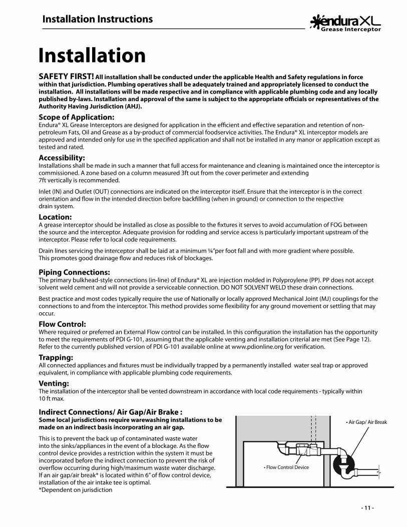
Installation Instructions
- 11 -
InstallationSAFETY FIRST! All installation shall be conducted under the applicable Health and Safety regulations in force within that jurisdiction. Plumbing operatives shall be adequately trained and appropriately licensed to conduct the installation. All installations will be made respective and in compliance with applicable plumbing code and any locally published by-laws. Installation and approval of the same is subject to the appropriate officials or representatives of the Authority Having Jurisdiction (AHJ).
Scope of Application:Endura® XL Grease Interceptors are designed for application in the efficient and effective separation and retention of non-petroleum Fats, Oil and Grease as a by-product of commercial foodservice activities. The Endura® XL interceptor models are approved and intended only for use in the specified application and shall not be installed in any manor or application except as tested and rated.
Accessibility: Installations shall be made in such a manner that full access for maintenance and cleaning is maintained once the interceptor is commissioned. A zone based on a column measured 3ft out from the cover perimeter and extending 7ft vertically is recommended.
Inlet (IN) and Outlet (OUT) connections are indicated on the interceptor itself. Ensure that the interceptor is in the correct orientation and flow in the intended direction before backfilling (when in ground) or connection to the respective drain system.
Location:A grease interceptor should be installed as close as possible to the fixtures it serves to avoid accumulation of FOG between the source and the interceptor. Adequate provision for rodding and service access is particularly important upstream of the interceptor. Please refer to local code requirements.
Drain lines servicing the interceptor shall be laid at a minimum ¼”per foot fall and with more gradient where possible. This promotes good drainage flow and reduces risk of blockages.
Piping Connections:The primary bulkhead-style connections (in-line) of Endura® XL are injection molded in Polyproylene (PP). PP does not accept solvent weld cement and will not provide a serviceable connection. DO NOT SOLVENT WELD these drain connections.
Best practice and most codes typically require the use of Nationally or locally approved Mechanical Joint (MJ) couplings for the connections to and from the interceptor. This method provides some flexibility for any ground movement or settling that may occur.
Flow Control:Where required or preferred an External Flow control can be installed. In this configuration the installation has the opportunity to meet the requirements of PDI G-101, assuming that the applicable venting and installation criterial are met (See Page 12). Refer to the currently published version of PDI G-101 available online at www.pdionline.org for verification.
Trapping:All connected appliances and fixtures must be individually trapped by a permanently installed water seal trap or approved equivalent, in compliance with applicable plumbing code requirements.
Venting:The installation of the interceptor shall be vented downstream in accordance with local code requirements - typically within 10 ft max.
• Air Gap/ Air Break
• Flow Control Device
Indirect Connections/ Air Gap/Air Brake :Some local jurisdictions require warewashing installations to be made on an indirect basis incorporating an air gap.
This is to prevent the back up of contaminated waste water into the sinks/appliances in the event of a blockage. As the flow control device provides a restriction within the system it must be incorporated before the indirect connection to prevent the risk of overflow occurring during high/maximum waste water discharge. If an air gap/air break* is located within 6” of flow control device, installation of the air intake tee is optimal. *Dependent on jurisdiction
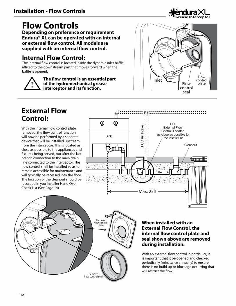
Installation - Flow Controls
- 12 -
Max. 25ft
FCD
Air
Inta
ke
PDI External Flow
Control. Located as close as possible to
the last fixture
Cleanout Cleanout
Sink
Flow
Max. 25ft(for PDI)
PDI External Flow Control installation
CleanoutCleanoutFCD
Air
Inta
ke
Sink
Inlet Outlet
External Flow Control:
When installed with an External Flow Control, the internal flow control plate and seal shown above are removed during installation.
With the internal flow control plate removed, the flow control function will now be performed by a separate device that will be installed upstream from the interceptor. This is located as close as possible to the appliances and fixtures being served, but after the last branch connection to the main drain line connected to the interceptor. The flow control shall be installed so as to remain accessible for maintenance and will typically be recessed into the floor. The location of the cleanout should be recorded in you Installer Hand Over Check List (See Page 14)
With an external flow control in particular, it is important that it be opened and checked periodically (min. twice annually) to ensure there is no build up or blockage occurring that will restrict the flow.
Removeflow control
plate
Removeflow control seal
Flow ControlsDepending on preference or requirement Endura® XL can be operated with an internal or external flow control. All models are supplied with an internal flow control.
Internal Flow Control: The internal flow control is located inside the dynamic inlet baffle, affixed to the downstream part that moves forward when the baffle is opened.
The flow control is an essential part of the hydromechanical grease interceptor and its function.
Flow control
plateFlow control
seal
Inlet

Installation - Remote Pump (Optional)
- 13 -
GREASE INTERCEPTOR
GREASE INTERCEPTOR
GREASE INTERCEPTOR
GREASE INTERCEPTOR
45˚ cut
XL75 36”
XL100 41”
Remote Pump (Optional): Endura® XL incorporates a method for installation of a Remote Pump function where desirable or required. The simplicity of this change is such that it can be conducted in the field with minimal materials. The installation is based on the use of a 3” DWV Sch40 pipe which is passed into the tank by means of a 3” diameter tank penetration seal (Part# 40100-TPS3”).
1. Cut the end of a 3” Sch40 DWV pipe (ABS or PVC by preference) at an angle that is no less than 45 degrees. 2. GOOD PREPARATION OF THIS PIPE END IS ESSENTIAL TO AVOID DAMAGING THE RUBBER SEAL WHEN BEING INSTALLED. The outer edges must be chamfered to at least 45 degrees around the full length of the pipe end.
3. Now measure from the end of the pipe to the following length depending if you are installing an XL75 or XL100 respectively. For XL75 pipe length 36”; For XL100 pipe length 44” (Fig A)
4. On the top surface of the tank at the center position and on either side of the air balance channel are two “Remote Pump Ready” details, both of which include a drill center (Fig. B). Select which of the two locations best suits your application and using a 4” diameter hole saw, open the respective hole.
Remote pump outlet
optional locations
Fig. A
Fig. B
5. Fit penetration tank seal (Part# 40100-TPS) into the opening prepared and lubricate well using silicone pipe lubricant.
6. As the orientation of the pipe when installed is important, mark or identify on the top of the pipe so as to indicate that the angled face of the pipe will be facing laterally across the interceptor when installed. i.e. the angled face is pointed toward the opposite tank wall.
7. Take your prepared length of pipe and liberally apply silicone pipe lubricant to at least the first 6” of the pipe ensuring that the angled surface is also well lubricated.
8. Introduce the pipe to the rubber seal and with even pressure and a rotating motion, push the pipe through the seal and into the tank. Once onto the full diameter of the pipe apply more lubricant to the next 12-18” and continue to push the pipe downward into the tank until the tip bottoms out, with the angled face in the correct position.
9. Develop your pump out line connecting to the pipe stub now extending from the tank using long sweep bends and fittings and making provision for adequate cleanout access as required. All joints must be solvent welded or of threaded format. Maximum developed pipe run shall be no greater than 30 feet with a vertical rise of 8 feet max.
10. At the extent of the remote pump system where the pumping service will be connected, typically a capped male camlock fitting (3”) will be provided to allow compatibility with vacuum service connection.
GREASE INTERCEPTOR
GREASE INTERCEPTOR
GREASE INTERCEPTOR
GREASE INTERCEPTOR
Max. 30ft
Max. 8ft
45˚ cut faces opposite tank wall
Long Sweep Bends
Tank Penetration
Seal (40100TPS3)
See Step
10
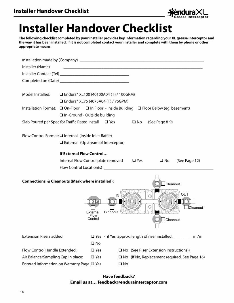
Installer Handover Checklist
- 14 -
Installation made by (Company) ___________________________________________________________
Installer (Name) __________________________________________________________________
Installer Contact (Tel) _________________________________
Completed on (Date) _________________________________
Model Installed: q Endura® XL100 (40100A04 (T) / 100GPM)
q Endura® XL75 (4075A04 (T) / 75GPM)
Installation Format: q On-Floor q In Floor - Inside Building q Floor Below (eg. basement)
q In-Ground - Outside building
Slab Poured per Spec for Traffic Rated Install q Yes q No (See Page 8-9)
Flow Control Format: q Internal (Inside Inlet Baffle)
q External (Upstream of Interceptor)
If External Flow Control…
Internal Flow Control plate removed q Yes q No (See Page 12)
Flow Control Location(s) ____________________________________________________
Connections & Cleanouts (Mark where installed):
Extension Risers added: q Yes - if Yes, approx. length of riser installed: _________in /m
q No
Flow Control Handle Extended: q Yes q No (See Riser Extension Instructions))
Air Balance/Sampling Cap in place: q Yes q No (If No, Replacement required. See Page 16)
Entered Information on Warranty Page q Yes q No
Have feedback? Email us at… [email protected]
Installer Handover ChecklistThe following checklist completed by your installer provides key information regarding your XL grease interceptor and the way it has been installed. If it is not completed contact your installer and complete with them by phone or other appropriate means.
GR
EASE
IN
TER
CEP
TORG
REA
SE INT
ERC
EPTO
RGR
EASE
IN
TER
CEP
TORG
REA
SE INT
ERC
EPTO
R
Cleanout
GR
EASE
IN
TER
CEP
TORG
REA
SE INT
ERC
EPTO
RGR
EASE
IN
TER
CEP
TORG
REA
SE INT
ERC
EPTO
R
OUTSIDE -
SIDE - OUT
END - OUTIN
OUTIN
Cleanout
CleanoutExternal Flow
Control
Cleanout
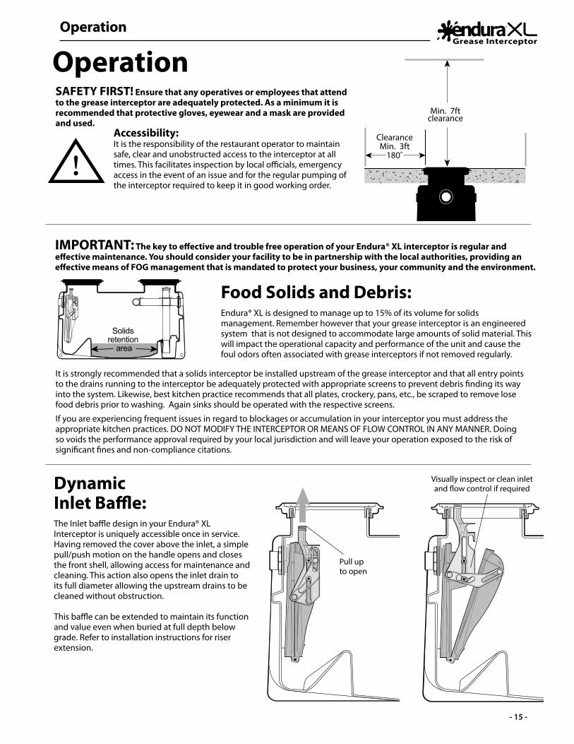
Operation
- 15 -
Operation
IMPORTANT: The key to effective and trouble free operation of your Endura® XL interceptor is regular and effective maintenance. You should consider your facility to be in partnership with the local authorities, providing an effective means of FOG management that is mandated to protect your business, your community and the environment.
Dynamic Inlet Baffle:The Inlet baffle design in your Endura® XL Interceptor is uniquely accessible once in service. Having removed the cover above the inlet, a simple pull/push motion on the handle opens and closes the front shell, allowing access for maintenance and cleaning. This action also opens the inlet drain to its full diameter allowing the upstream drains to be cleaned without obstruction.
This baffle can be extended to maintain its function and value even when buried at full depth below grade. Refer to installation instructions for riser extension.
Pull upto open
Visually inspect or clean inlet and flow control if required
Food Solids and Debris:Endura® XL is designed to manage up to 15% of its volume for solids management. Remember however that your grease interceptor is an engineered system that is not designed to accommodate large amounts of solid material. This will impact the operational capacity and performance of the unit and cause the foul odors often associated with grease interceptors if not removed regularly.
It is strongly recommended that a solids interceptor be installed upstream of the grease interceptor and that all entry points to the drains running to the interceptor be adequately protected with appropriate screens to prevent debris finding its way into the system. Likewise, best kitchen practice recommends that all plates, crockery, pans, etc., be scraped to remove lose food debris prior to washing. Again sinks should be operated with the respective screens.
If you are experiencing frequent issues in regard to blockages or accumulation in your interceptor you must address the appropriate kitchen practices. DO NOT MODIFY THE INTERCEPTOR OR MEANS OF FLOW CONTROL IN ANY MANNER. Doing so voids the performance approval required by your local jurisdiction and will leave your operation exposed to the risk of significant fines and non-compliance citations.
Solids retention
area
ClearanceMin. 3ft
180˚
Min. 7ftclearance
SAFETY FIRST! Ensure that any operatives or employees that attend to the grease interceptor are adequately protected. As a minimum it is recommended that protective gloves, eyewear and a mask are provided and used.
Accessibility:It is the responsibility of the restaurant operator to maintain safe, clear and unobstructed access to the interceptor at all times. This facilitates inspection by local officials, emergency access in the event of an issue and for the regular pumping of the interceptor required to keep it in good working order.
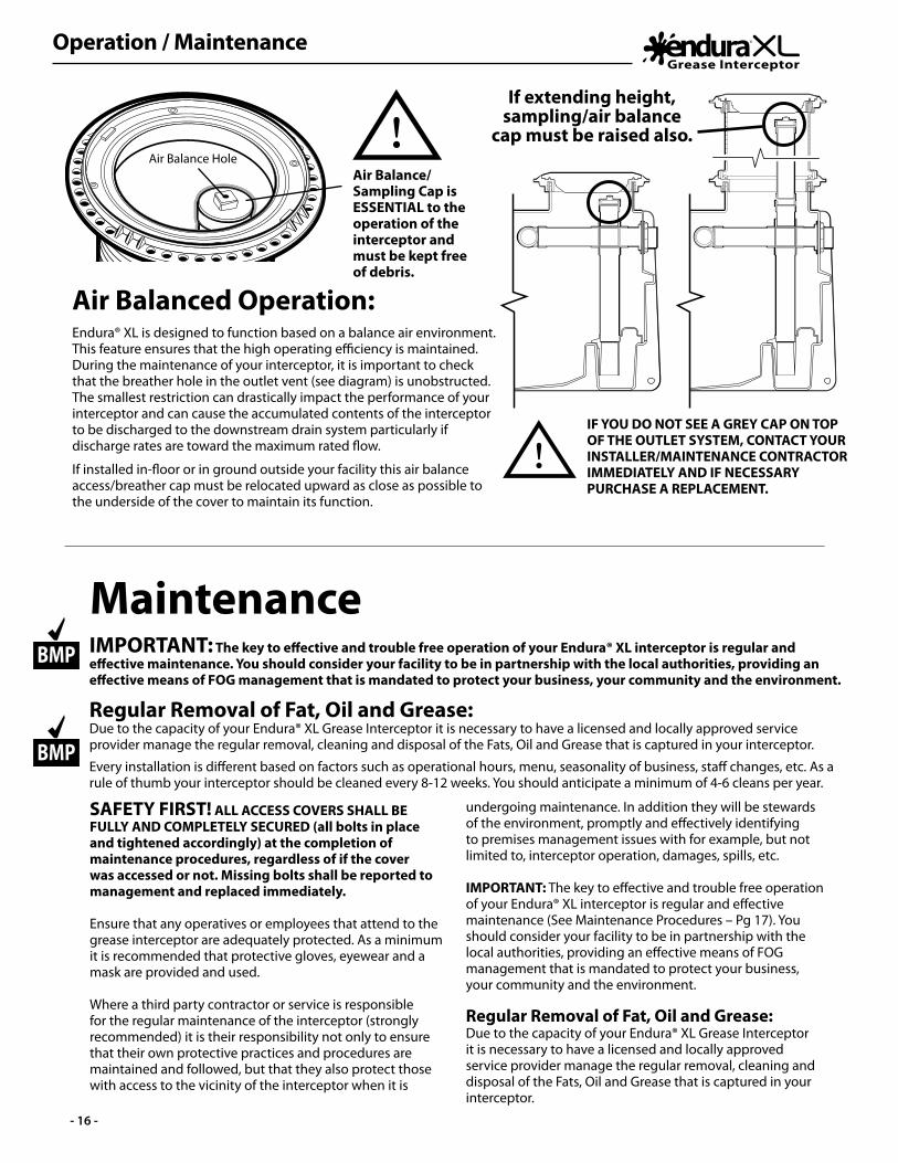
Operation / Maintenance
- 16 -
SAFETY FIRST! ALL ACCESS COVERS SHALL BE FULLY AND COMPLETELY SECURED (all bolts in place and tightened accordingly) at the completion of maintenance procedures, regardless of if the cover was accessed or not. Missing bolts shall be reported to management and replaced immediately.
Ensure that any operatives or employees that attend to the grease interceptor are adequately protected. As a minimum it is recommended that protective gloves, eyewear and a mask are provided and used.
Where a third party contractor or service is responsible for the regular maintenance of the interceptor (strongly recommended) it is their responsibility not only to ensure that their own protective practices and procedures are maintained and followed, but that they also protect those with access to the vicinity of the interceptor when it is
Air Balanced Operation:Endura® XL is designed to function based on a balance air environment. This feature ensures that the high operating efficiency is maintained. During the maintenance of your interceptor, it is important to check that the breather hole in the outlet vent (see diagram) is unobstructed. The smallest restriction can drastically impact the performance of your interceptor and can cause the accumulated contents of the interceptor to be discharged to the downstream drain system particularly if discharge rates are toward the maximum rated flow.
If installed in-floor or in ground outside your facility this air balance access/breather cap must be relocated upward as close as possible to the underside of the cover to maintain its function.
IF YOU DO NOT SEE A GREY CAP ON TOP OF THE OUTLET SYSTEM, CONTACT YOUR INSTALLER/MAINTENANCE CONTRACTOR IMMEDIATELY AND IF NECESSARY PURCHASE A REPLACEMENT.
Air Balance/Sampling Cap is ESSENTIAL to the operation of the interceptor and must be kept free of debris.
If extending height, sampling/air balance
cap must be raised also. Air Balance Hole
MaintenanceIMPORTANT: The key to effective and trouble free operation of your Endura® XL interceptor is regular and effective maintenance. You should consider your facility to be in partnership with the local authorities, providing an effective means of FOG management that is mandated to protect your business, your community and the environment.
Regular Removal of Fat, Oil and Grease: Due to the capacity of your Endura® XL Grease Interceptor it is necessary to have a licensed and locally approved service provider manage the regular removal, cleaning and disposal of the Fats, Oil and Grease that is captured in your interceptor.
Every installation is different based on factors such as operational hours, menu, seasonality of business, staff changes, etc. As a rule of thumb your interceptor should be cleaned every 8-12 weeks. You should anticipate a minimum of 4-6 cleans per year.
BMP
BMP
undergoing maintenance. In addition they will be stewards of the environment, promptly and effectively identifying to premises management issues with for example, but not limited to, interceptor operation, damages, spills, etc.
IMPORTANT: The key to effective and trouble free operation of your Endura® XL interceptor is regular and effective maintenance (See Maintenance Procedures – Pg 17). You should consider your facility to be in partnership with the local authorities, providing an effective means of FOG management that is mandated to protect your business, your community and the environment.
Regular Removal of Fat, Oil and Grease:Due to the capacity of your Endura® XL Grease Interceptor it is necessary to have a licensed and locally approved service provider manage the regular removal, cleaning and disposal of the Fats, Oil and Grease that is captured in your interceptor.

Maintenance
- 17 -
Maintenance Procedures:
Removal of Access Cover:The covers that provide access to the XL interceptors are retained with four (4) standard hex head bolts which are removed with a ½” socket/driver. These bolts have a retraining washer on the reverse to prevent them falling out of their location when the cover is removed from the interceptor.
Covers incorporate pry points for ease of removal. Each cover weighs approximately 22lbs (10kg) so take care when lifting and moving the cover. Always set aside the cover on a flat surface when removed.On reinstallation visually check the seal recessed in the underside of the cover and when satisfied refit the cover being sure not to overtighten the bolts. Maximum torque is 80-100 ft/lb.
Access to the Dynamic Inlet Baffle (Internal Flow Control where used):The Dynamic Inlet Baffle is a unique element of Endura® XL allowing access to the internal surfaces for maintenance, inspection and cleaning.
To open the baffle, take a firm grip on the handle and pull vertically upward. The handle will move approximately 6” in the vertical direction. In doing so the front shell of the baffle moves away from the fixed rear portion providing access to the internal flow control plate (where fitted).
The flow control plate is securely retained but is intended to be removable during installation, should an external flow control be the preferred format of installation.
Once open, visual inspection can be made inside the baffle. Any debris is best removed with a low pressure source of warm water – approx. 38˚C (100˚F)
To close the baffle, push vertically downward on the handle until it returns to the full closed and locked position
Drain Cleaning/Inspection:For cleaning and inspection of the upstream drain, it is strongly recommended that the inlet baffle be in the open position. This will reduce the risk of damage to the internal flow control (where fitted) by rooting or other equipment.
Access to the Outlet Well:Although essentially a closed area, the outlet system is able to be accessed by removal of the Sampling/Air Balance Cap. Once removed the 4” vertical pipe is able to be visually inspected all the way to the bottom (with the unit pumped out), and in the event of any accumulation can be cleaned by vacuum or pressurized water, either withdrawing debris out or back into the tank respectively.
Pumping and Cleaning:The complete removal of grease and water should be done at every pump out. This ensures all solids, grease and water are removed allowing visual inspection and removal of any residue. Any residue is best removed with a hot water source rinsing the walls and internal components into the tank before making a final vacuum extraction.
The tank must be re-filled to static water level on completion of pumping. An interceptor cannot function without water.
Remote Pump Out (Optional):An installation fitted with the remote pumping option offers convenience for the pumper and the restaurant operator, but also presents risk. Where installed and operated with a remote pump facility, the interceptor should be physically opened and inspected at least every third pumping, or twice a year, whichever is sooner. This is to ensure that the internal parts are in good working order and that there is no undue build-up of residue or solids remaining in the tank once it has been emptied. This also presents opportunity to open and inspect the inside of the inlet baffle system, and clean/inspect the outlet well. Any residue will be removed with a warm water source.
BMP Remember: Every installation is different based on factors such as operational hours, menu, seasonality of business, staff changes, etc. As a rule of thumb your interceptor should be cleaned every 8-12 weeks. You should anticipate a minimum of 4 cleans per year.
Pull upto open
Push down to close
Internal Baffle in closed position
Internal Baffle in open
position for inspection
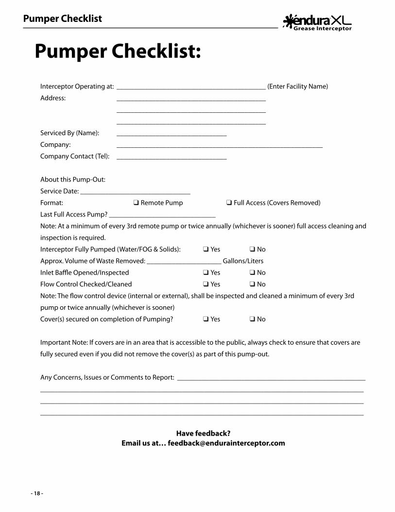
Pumper Checklist
- 18 -
Interceptor Operating at: __________________________________________ (Enter Facility Name)
Address: __________________________________________
__________________________________________
__________________________________________
Serviced By (Name): _______________________________
Company: __________________________________________________________
Company Contact (Tel): _______________________________
About this Pump-Out:
Service Date: _______________________________
Format: q Remote Pump q Full Access (Covers Removed)
Last Full Access Pump? ______________________________
Note: At a minimum of every 3rd remote pump or twice annually (whichever is sooner) full access cleaning and
inspection is required.
Interceptor Fully Pumped (Water/FOG & Solids): q Yes q No
Approx. Volume of Waste Removed: _____________________ Gallons/Liters
Inlet Baffle Opened/Inspected q Yes q No
Flow Control Checked/Cleaned q Yes q No
Note: The flow control device (internal or external), shall be inspected and cleaned a minimum of every 3rd
pump or twice annually (whichever is sooner)
Cover(s) secured on completion of Pumping? q Yes q No
Important Note: If covers are in an area that is accessible to the public, always check to ensure that covers are
fully secured even if you did not remove the cover(s) as part of this pump-out.
Any Concerns, Issues or Comments to Report: _____________________________________________________
___________________________________________________________________________________________
___________________________________________________________________________________________
___________________________________________________________________________________________
Have feedback? Email us at… [email protected]
Pumper Checklist:
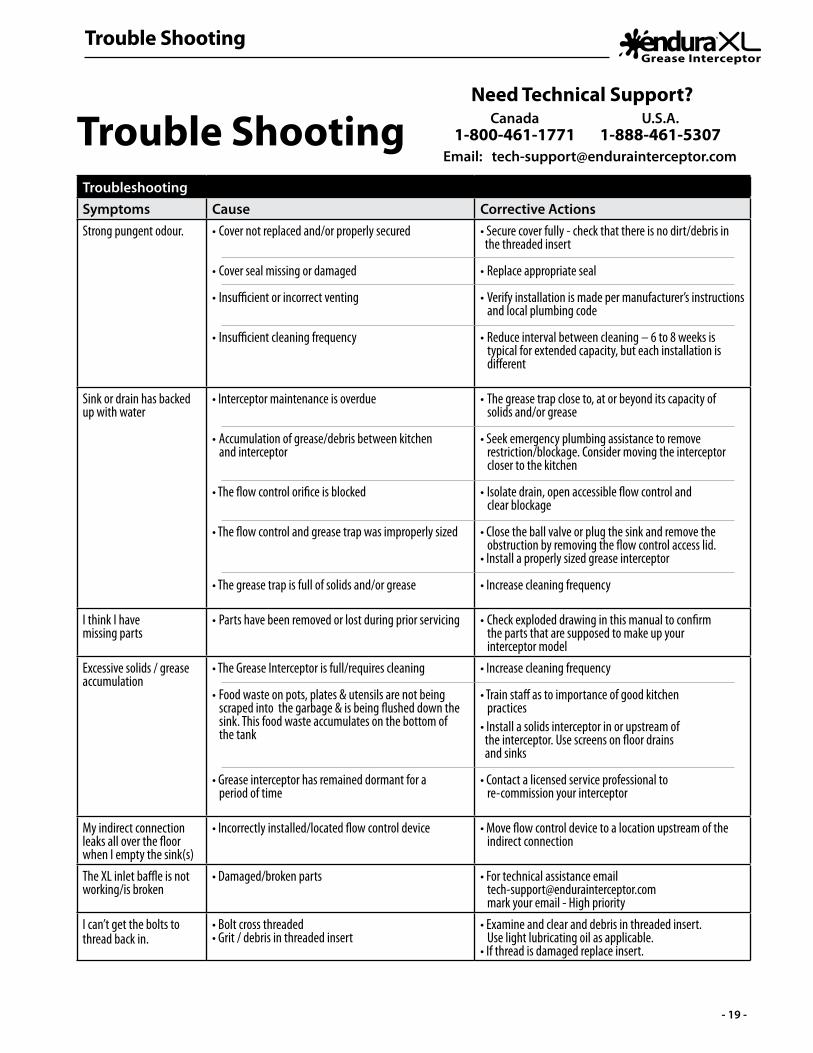
Trouble Shooting
- 19 -
Trouble ShootingTroubleshootingSymptoms Cause Corrective ActionsStrong pungent odour. • Cover not replaced and/or properly secured
• Cover seal missing or damaged
• Insufficient or incorrect venting
• Insufficient cleaning frequency
• Secure cover fully - check that there is no dirt/debris in the threaded insert
• Replace appropriate seal
• Verify installation is made per manufacturer’s instructions and local plumbing code
• Reduce interval between cleaning – 6 to 8 weeks is typical for extended capacity, but each installation is different
Sink or drain has backed up with water
• Interceptor maintenance is overdue
• Accumulation of grease/debris between kitchen and interceptor
• The flow control orifice is blocked
• The flow control and grease trap was improperly sized
• The grease trap is full of solids and/or grease
• The grease trap close to, at or beyond its capacity of solids and/or grease
• Seek emergency plumbing assistance to remove restriction/blockage. Consider moving the interceptor closer to the kitchen
• Isolate drain, open accessible flow control and clear blockage
• Close the ball valve or plug the sink and remove the obstruction by removing the flow control access lid.• Install a properly sized grease interceptor
• Increase cleaning frequency
I think I have missing parts
• Parts have been removed or lost during prior servicing • Check exploded drawing in this manual to confirm the parts that are supposed to make up your interceptor model
Excessive solids / greaseaccumulation
• The Grease Interceptor is full/requires cleaning
• Food waste on pots, plates & utensils are not being scraped into the garbage & is being flushed down the sink. This food waste accumulates on the bottom of the tank
• Grease interceptor has remained dormant for a period of time
• Increase cleaning frequency
• Train staff as to importance of good kitchen practices• Install a solids interceptor in or upstream of the interceptor. Use screens on floor drains and sinks
• Contact a licensed service professional to re-commission your interceptor
My indirect connection leaks all over the floor when I empty the sink(s)
• Incorrectly installed/located flow control device • Move flow control device to a location upstream of the indirect connection
The XL inlet baffle is not working/is broken
• Damaged/broken parts • For technical assistance email [email protected] mark your email - High priority
I can’t get the bolts to thread back in.
• Bolt cross threaded• Grit / debris in threaded insert
• Examine and clear and debris in threaded insert. Use light lubricating oil as applicable. • If thread is damaged replace insert.
Need Technical Support?Canada
1-800-461-1771Email: [email protected]
U.S.A.1-888-461-5307

Frequently Asked Questions
- 20 -
Frequently Asked QuestionsFollowing are just a few of the common terms and questions we receive regarding Grease Management.
How do I size a Grease Interceptor correctly?A grease interceptor can be sized using two primary methods - Flow rate or capacity
Sizing by Flow Rate
Table A - Procedure for Sizing Grease Interceptors
STEP FORMULA EXAMPLE1 Determine cubic content of fixture by multiplying length x
width x depthA sink 24” long by 20” wide by 12” deep.Cubic content: 24 x 20 x 12 = 5,760 cu in
(61.0 x 50.8 x 30.48 cm3 )2 Determine capacity in gallons.
1 gallon = 231 cu inContents in gallons:
5,760 / 231 = 24.9 gallons(94,451.42 / 1,000 = 94.45 litres)
3 Determine actual drainage load.
The fixture is normally filled to approximately 75% of capacity with water as the items being washed displace about 25% of
the total fixture content.
Actual drainage load = 75% of fixture capacity
Actual drainage load:.75 x 24.9 = 18.7 gallons
(0.75 x 94.45 = 70.84 litres)
4 Determine flow rate and drainage period.In general, good practice dictates a one minute drainage peri-od; however, where conditions permit, a two minute drainage period is acceptable. Drainage period is defined as the actual
time required to completely drain the fixture.Flow rate = Actual Drainage Load
Drainage Period
Calculate flow rate for one minute drainage period:18.7 / 1 = 18.7 g.p.m. flow rate(70.84 / 1 min. = 70.84 l.p.m.)
Calculate flow rate for two minute drainage period:18.7 / 2 = 9.4 g.p.m. flow rate(70.84 / 2 min. = 35.42 l.p.m.)
5 Select Interceptor.From Table B select the interceptor with a flow rating at least
equal to the calculated flow rate. When the calculated flow rate falls between two sizes, select the larger of the two
interceptors.
For a one minute drainage period:18.7 g.p.m. (70.84 l.p.m.) flow rate = 20 g.p.m. G.I.
For a two minute drainage period:9.4 g.p.m. (35.42 l.p.m.) flow rate = 10 g.p.m. G.I.
Table B -Metric conversions based on PDI sizes
PDI Size 4 7 10 15 20 25 35 50 75 100Flow Rate US Gallons per Minute (gpm) 4 7 10 15 20 25 35 50 75 100Flow Rate Liters per Second (L/Sec) .25 .44 .63 .95 1.26 1.58 2.20 3.16 4.74 6.3Grease Capacity Min. (lb) 8 14 20 30 40 50 70 100 150 200Grease Capacity Min. (kg) 3.63 6.35 9.07 13.61 18.14 22.68 31.75 45.36 68 91
It is reccomended that HGI’s such as Endura® interceptors are sized by flow rate. The use of a flow control with a Hydromechanical Grease Interceptor is considered mandatory. Without a properly sized flow control, the discharge rate through into the interceptor may exceed the design rating of the unit, causing lower efficiencies and increase the risk of grease, passing into the downstream system. Be careful not to confuse liquid capacity and flow rate. Liquid capacity is stated in gallons (or liters) while flow rate is referenced in gallons per minute (GPM) or liters per second (L/Sec).
Fixture Capacity: Most commonly used and recommended method for Hydromechanical Grease Interceptors. This method looks at the maximum capacity of fixtures connected to the interceptor and the time taken to discharge that volume of wastewater through the interceptor. Units are expressed in Gallons Per Minute (gpm).
Calculation takes 75% of maximum capacity of all fixtures and based on a 1 or 2 minute period of time taken to discharge, results in a gallons per minute flow rate. This number is rounded up to the next available size of interceptor, i.e. 16.7gpm become a 20gpm Grease Interceptor.
Pipe Size:
Pipe Diameter
Maximum Flow Rate
(gpm)
Size of interceptor 1-minute drain period (gpm)
Size of interceptor 2-minute drain period
(gpm)2-inch 20 20 103-inch 60 75 354-inch 125 150 75
Use our simple online sizing calculator and DFU conversion at...
www.SizeMyGI.net
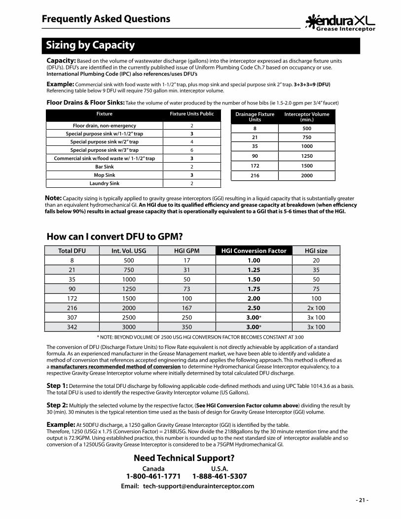
Frequently Asked Questions
- 21 -
Need Technical Support?Canada
1-800-461-1771Email: [email protected]
U.S.A.1-888-461-5307
Sizing by CapacityCapacity: Based on the volume of wastewater discharge (gallons) into the interceptor expressed as discharge fixture units (DFU’s). DFU’s are identified in the currently published issue of Uniform Plumbing Code Ch.7 based on occupancy or use. International Plumbing Code (IPC) also references/uses DFU’s
Note: Capacity sizing is typically applied to gravity grease interceptors (GGI) resulting in a liquid capacity that is substantially greater than an equivalent hydromechanical GI. An HGI due to its qualified efficiency and grease capacity at breakdown (when efficiency falls below 90%) results in actual grease capacity that is operationally equivalent to a GGI that is 5-6 times that of the HGI.
Example: Commercial sink with food waste with 1-1/2” trap, plus mop sink and special purpose sink 2” trap. 3+3+3=9 (DFU)Referencing table below 9 DFU will require 750 gallon min. interceptor volume.
Floor Drains & Floor Sinks: Take the volume of water produced by the number of hose bibs (ie 1.5-2.0 gpm per 3/4” faucet)
Drainage Fixture Units
Interceptor Volume(min.)
8 500
21 750
35 1000
90 1250
172 1500
216 2000
Fixture Fixture Units Public
Floor drain, non-emergency 2
Special purpose sink w/1-1/2” trap 3Special purpose sink w/2” trap 4
Special purpose sink w/3” trap 6
Commercial sink w/food waste w/ 1-1/2” trap 3
Bar Sink 2
Mop Sink 3
Laundry Sink 2
Total DFU Int. Vol. USG HGI GPM HGI Conversion Factor HGI size8 500 17 1.00 20
21 750 31 1.25 3535 1000 50 1.50 5090 1250 73 1.75 75
172 1500 100 2.00 100216 2000 167 2.50 2x 100307 2500 250 3.00* 3x 100342 3000 350 3.00* 3x 100
How can I convert DFU to GPM?
* NOTE: BEYOND VOLUME OF 2500 USG HGI CONVERSION FACTOR BECOMES CONSTANT AT 3:00
The conversion of DFU (Discharge Fixture Units) to Flow Rate equivalent is not directly achievable by application of a standard formula. As an experienced manufacturer in the Grease Management market, we have been able to identify and validate a method of conversion that references accepted engineering data and applies the following approach. This method is offered as a manufacturers recommended method of conversion to determine Hydromechanical Grease Interceptor equivalency, to a respective Gravity Grease Interceptor volume where initially determined by total calculated DFU discharge. Step 1: Determine the total DFU discharge by following applicable code-defined methods and using UPC Table 1014.3.6 as a basis. The total DFU is used to identify the respective Gravity Interceptor volume (US Gallons).
Step 2: Multiply the selected volume by the respective factor, (See HGI Conversion Factor column above) dividing the result by 30 (min). 30 minutes is the typical retention time used as the basis of design for Gravity Grease Interceptor (GGI) volume. Example: At 50DFU discharge, a 1250 gallon Gravity Grease Interceptor (GGI) is identified by the table. Therefore, 1250 (USG) x 1.75 (Conversion Factor) = 2188USG. Now divide the 2188gallons by the 30 minute retention time and the output is 72.9GPM. Using established practice, this number is rounded up to the next standard size of interceptor available and so conversion of a 1250USG Gravity Grease Interceptor is considered to be a 75GPM Hydromechanical GI.
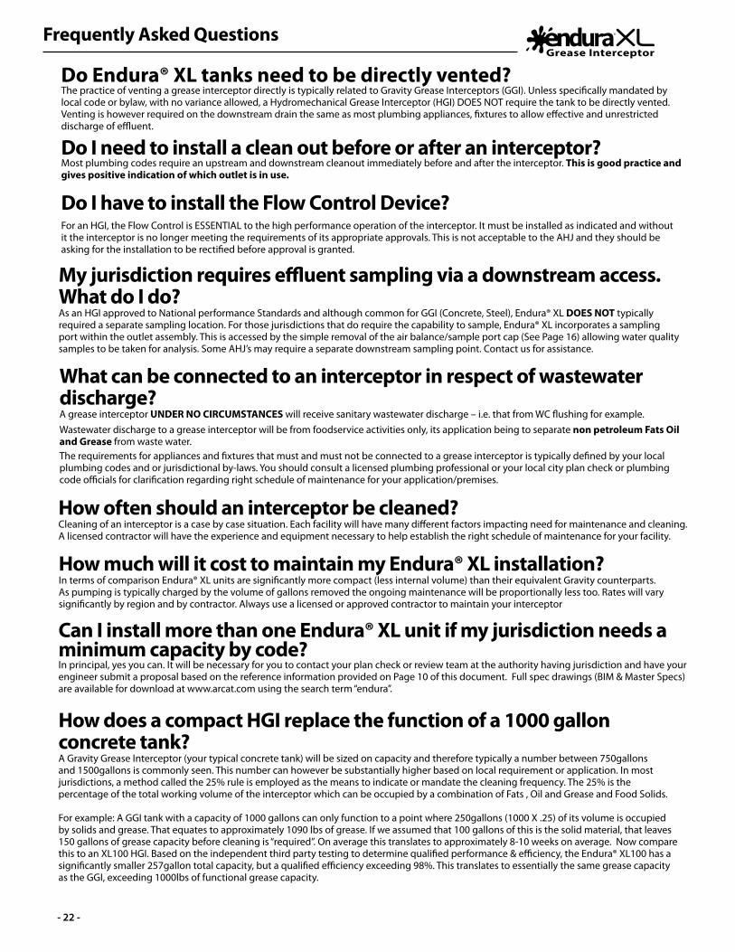
Frequently Asked Questions
- 22 -
How does a compact HGI replace the function of a 1000 gallon concrete tank?A Gravity Grease Interceptor (your typical concrete tank) will be sized on capacity and therefore typically a number between 750gallons and 1500gallons is commonly seen. This number can however be substantially higher based on local requirement or application. In most jurisdictions, a method called the 25% rule is employed as the means to indicate or mandate the cleaning frequency. The 25% is the percentage of the total working volume of the interceptor which can be occupied by a combination of Fats , Oil and Grease and Food Solids.
For example: A GGI tank with a capacity of 1000 gallons can only function to a point where 250gallons (1000 X .25) of its volume is occupied by solids and grease. That equates to approximately 1090 lbs of grease. If we assumed that 100 gallons of this is the solid material, that leaves 150 gallons of grease capacity before cleaning is “required”. On average this translates to approximately 8-10 weeks on average. Now compare this to an XL100 HGI. Based on the independent third party testing to determine qualified performance & efficiency, the Endura® XL100 has a significantly smaller 257gallon total capacity, but a qualified efficiency exceeding 98%. This translates to essentially the same grease capacity as the GGI, exceeding 1000lbs of functional grease capacity.
Can I install more than one Endura® XL unit if my jurisdiction needs a minimum capacity by code? In principal, yes you can. It will be necessary for you to contact your plan check or review team at the authority having jurisdiction and have your engineer submit a proposal based on the reference information provided on Page 10 of this document. Full spec drawings (BIM & Master Specs) are available for download at www.arcat.com using the search term “endura”.
How often should an interceptor be cleaned? Cleaning of an interceptor is a case by case situation. Each facility will have many different factors impacting need for maintenance and cleaning. A licensed contractor will have the experience and equipment necessary to help establish the right schedule of maintenance for your facility.
How much will it cost to maintain my Endura® XL installation?In terms of comparison Endura® XL units are significantly more compact (less internal volume) than their equivalent Gravity counterparts. As pumping is typically charged by the volume of gallons removed the ongoing maintenance will be proportionally less too. Rates will vary significantly by region and by contractor. Always use a licensed or approved contractor to maintain your interceptor
Do Endura® XL tanks need to be directly vented?The practice of venting a grease interceptor directly is typically related to Gravity Grease Interceptors (GGI). Unless specifically mandated by local code or bylaw, with no variance allowed, a Hydromechanical Grease Interceptor (HGI) DOES NOT require the tank to be directly vented. Venting is however required on the downstream drain the same as most plumbing appliances, fixtures to allow effective and unrestricted discharge of effluent.
Do I need to install a clean out before or after an interceptor?Most plumbing codes require an upstream and downstream cleanout immediately before and after the interceptor. This is good practice and gives positive indication of which outlet is in use.
Do I have to install the Flow Control Device?For an HGI, the Flow Control is ESSENTIAL to the high performance operation of the interceptor. It must be installed as indicated and without it the interceptor is no longer meeting the requirements of its appropriate approvals. This is not acceptable to the AHJ and they should be asking for the installation to be rectified before approval is granted.
My jurisdiction requires effluent sampling via a downstream access. What do I do?As an HGI approved to National performance Standards and although common for GGI (Concrete, Steel), Endura® XL DOES NOT typically required a separate sampling location. For those jurisdictions that do require the capability to sample, Endura® XL incorporates a sampling port within the outlet assembly. This is accessed by the simple removal of the air balance/sample port cap (See Page 16) allowing water quality samples to be taken for analysis. Some AHJ’s may require a separate downstream sampling point. Contact us for assistance.
What can be connected to an interceptor in respect of wastewater discharge?A grease interceptor UNDER NO CIRCUMSTANCES will receive sanitary wastewater discharge – i.e. that from WC flushing for example. Wastewater discharge to a grease interceptor will be from foodservice activities only, its application being to separate non petroleum Fats Oil and Grease from waste water.The requirements for appliances and fixtures that must and must not be connected to a grease interceptor is typically defined by your local plumbing codes and or jurisdictional by-laws. You should consult a licensed plumbing professional or your local city plan check or plumbing code officials for clarification regarding right schedule of maintenance for your application/premises.
Warranty
- 23 -
Canplas Industries Ltd. hereafter referred to as “Manufacturer” guarantees to the original consumer purchaser (“Original Purchaser”) of Endura® XL Grease Management Products (hereafter referred to as “Products”) that Manufacturer will replace any such Products that are defective in materials or workmanship, subject to the limitations detailed herein. If replacement is not commercially practical or cannot be made in a timely manner, then the Manufacturer will, at its discretion, refund the purchase price. This warranty applies only to Products installed in a commercial application. THIS EXPRESS WARRANTY IS IN LIEU OF AND EXCLUDES ALL OTHER WARRANTIES, WHETHER EXPRESSED, IMPLIED OR STATUTORY, INCLUDING IMPLIED WARRANTIES OF MERCHANTABILITY OR FITNESS FOR A PARTICULAR PURPOSE. THIS EXPRESS WARRANTY SPECIFICALLY EXCLUDES INSTALLATION AND/OR REPAIR COSTS, INCLUDING LABOUR.
The Products have a limited warranty from the date of purchase against defects in workmanship and materials. Any Product believed to be defective must be returned to the Manufacturers’ manufacturing facility located at 31 Patterson Road, Barrie, Ontario, Canada L4N 3V9 with freight prepaid, or, at Manufacturers’ sole discretion, an on-site inspection may be arranged. The Manufacturer reserves the right to inspect all allegedly defective Products. Any products found to be defective following examinations will be replaced free of charge and returned freight prepaid at the absolute discretion of the Manufacturer. All products returned under this warranty must have proof of purchase information included.
LimitationsThis Warranty applies provided that the Products have been installed in strict compliance with the Manufacturers’ written instructions, as published from time to time, and in accordance with all local codes and standards. This Warranty does not cover any labour costs, including those required for field repair or replacement or removal of any allegedly defective part. This Warranty does not cover any consequential, incidental, special or punitive damages related to the allegedly defective Product.
This Warranty does not cover damage or defects as a result of normal wear and tear, improper operation, abuse or alterations to the Products, if the Products have been used in more than one installation, installed in improper applications, acts of nature, building settling, structural failures of constructed walls or foundations, improper installation, storage, handling, failure to properly care for and maintain the Products or any other cause outside the control of the Manufacturer.
The Manufacturer reserves the right to discontinue or modify any of its Products at its absolute discretion, and shall not be liable as a result of such discontinuation or modification. The Manufacturer may replace any product under this Warranty, at its absolute discretion, with substitute Products of comparable quality and/or price range in the event the original Product has been discontinued or modified.
TransferabilityIn the event of a change in ownership the Warranty may be transferred by the Original Purchaser of the Product to the first subsequent owner, subject to the terms and conditions of this Warranty.
Other ConditionsThis Warranty is expressly in lieu of all other oral or written warranties, liabilities or obligations of the Manufacturer. Pertinent State, Provincial or Federal law shall control for what period of time subsequent to sale an owner may seek a remedy pursuant to the implied warranty of merchantability or fitness for a particular purpose. In no event, shall the Manufacturer be liable for consequential or incidental damages of any kind, including any damage to the building, its contents or any persons therein, resulting from the breach of any warranty set forth herein, unless exclusion of these types of damages are specifically prohibited by State, Provincial or Federal law. No field representative of the Manufacturer or any distributor or dealer is authorized to make any change or modifications to this Warranty. While this Warranty gives you specific legal rights you may also have other rights that vary depending on your locality.
Limited Lifetime Warranty
I heard that plastic tanks can float in high water table areas, particularly when pumped down for cleaning. Is this true?Yes it is, however Endura® XL is specifically designed to address this challenge. If you look at XL tanks from the end you will see that the top is narrower than the bottom and that there are along the sides corrugations that are closed toward the bottom of their profile. This profile is the reverse of an ice cube sitting in a freezer tray. Typically some upward force is applied around or beneath the ice cube and out it pops! Now reverse that principle to the form of the tanks – the broad base not only provides stability but also has substantial resistance to being forced upward by water or freeze-thaw action. This in conjunction with the closed corrugations positively captures the tank in the excavation once backfilled. For areas of particular concern in addition an 8” concrete slab can be poured around the base to introduce further resistance. Provision is also made for the use of ground anchors or alternates that will need to be specified locally by an engineer respective of local ground conditions.
Have feedback? Email us at… [email protected]
Warranty
- 24 -
• Size of Grease Interceptor installed?
q 75 gpm q Threaded Connection q Traffic Ratq 100 gpm q No-Hub Connection q No-Hub Connection • Flow Control Format?q Internal Flow Control q External Flow Control • Is this installation...q New q Replacement
• Where was it installed?q On Floor q In Floor - Inside Building q Floor Below (eg. basement)q In-Ground - Outside building
• How did you hear about the product? q Supplier q Trade Show q Trade Magazine q Specifiedq Referral q Online
• Was this the first Endura® XL Grease Interceptor you have installed? q Yes q No
• How do you rate Endura® XL based on experience of past installations? q q q q q q q q q q 1 2 3 4 5 6 7 8 9 10
Have feeback? Email us… [email protected]
Limited Lifetime Warranty Registration CardCongratulations on your purchase of the Endura® XL Grease Interceptor. This product is supplied with a Limited Lifetime warranty (see page 23), valid only when this warranty card is filled out and returned to the manufacturer.
Online warranty registration at www.EnduraWarranty.com
• Client/Installation Location Name:
Address:
Tel:
Fax:
• Contractor/Installer (Print):Name:
Company:
Address:
Tel :
Fax :
Installer Signature
• Purchased From:
Name:
Address:
Tel:
Fax:
Important:
Printed in Canada GD1530-EN-05-17
CanadaTel: (705) 726-3361 1-800-461-1771Fax: (705) 726-2186
Technical [email protected]
U.S.A.Tel: (303) 373-1918 1-888-461-5307Fax: (303) 373-1923
Endura brand products manufactured by Canplas Industries.