Embed Size (px)
Citation preview
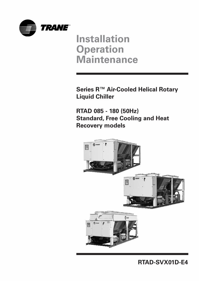
InstallationOperationMaintenance
RTAD-SVX01D-E4
Series R™ Air-Cooled Helical Rotary
Liquid Chiller
RTAD 085 - 180 (50Hz)
Standard, Free Cooling and Heat
Recovery models
RTAD-SVX01D-E4©American Standard Inc. 2005
Foreword
These instructions are given as aguide to good practice in theinstallation, start-up, operation, andmaintenance by the user, of TraneRTAD chillers. They do not containfull service proceduresnecessary for the continuedsuccessful operation of thisequipment. The services of a qualifiedtechnician should be employedthrough the medium of amaintenance contract with areputable service company. Readthis manual thoroughly before unitstart-up.
Units are assembled, pressure tested,dehydrated, charged and run testedbefore shipment.
Warnings and cautions
Warnings and Cautions appear atappropriate sections throughout thismanual. Your personal safety and theproper operation of this machinerequire that you follow themcarefully. The constructor assumes noliability for installations or servicingperformed by unqualified personnel.WARNING! Indicates a potentiallyhazardous situation which, if notavoided, could result in death orserious injury.CAUTION! Indicates a potentiallyhazardous situation which, if notavoided, may result in minor ormoderate injury. It may also be usedto alert against unsafe practices or forequipment or property-damage-onlyaccidents.
Safety recommendations
To avoid death, injury, equipment orproperty damage, the followingrecommendations should beobserved during maintenance andservice visits:1. The maximum allowable pressures
for system leak testing on low andhigh pressure side are given in thechapter "Installation". Alwaysprovide a pressure regulator.
2. Disconnect the main power supplybefore any servicing on the unit.
3. Service work on the refrigerationsystem and the electrical systemshould be carried out only byqualified and experiencedpersonnel.
Reception
On arrival, inspect the unit beforesigning the delivery note.
Reception in France only:
In case of visible damage: Theconsignee (or the site representative)must specify any damage on thedelivery note, legibly sign and datethe delivery note, and the truck drivermust countersign it. The consignee(or the site representative) mustnotify Trane Epinal Operations -Claims team and send a copy of thedelivery note. The customer (or thesite representative) should send aregistered letter to the last carrierwithin 3 days of delivery.Note: for deliveries in France, evenconcealed damage must be lookedfor at delivery and immediatelytreated as visible damage.
Reception in all countries except
France:
In case of concealed damage: Theconsignee (or the site representative)must send a registered letter to the lastcarrier within 7 days of delivery,claiming for the described damage. Acopy of this letter must be sent toTrane Epinal Operations - Claims team.
Warranty
Warranty is based on the generalterms and conditions of themanufacturer. The warranty is void ifthe equipment is repaired ormodified without the writtenapproval of the manufacturer, if theoperating limits are exceeded or ifthe control system or the electricalwiring is modified. Damage due tomisuse, lack of maintenance orfailure to comply with themanufacturer's instructions orrecommendations is not covered bythe warranty obligation. If the userdoes not conform to the rules of thismanual, it may entail cancellation ofwarranty and liabilities by themanufacturer.
Refrigerant
The refrigerant provided by themanufacturer meets all therequirements of our units. Whenusing recycled or reprocessedrefrigerant, it is advisable to ensureits quality is equivalent to that of anew refrigerant. For this, it isnecessary to have a precise analysismade by a specialized laboratory. Ifthis condition is not respected, themanufacturer warranty could becancelled.
Maintenance contract
It is strongly recommended that yousign a maintenance contract withyour local Service Agency. Thiscontract provides regularmaintenance of your installation by aspecialist in our equipment. Regularmaintenance ensures that anymalfunction is detected and correctedin good time and minimizes thepossibility that serious damage willoccur. Finally, regular maintenanceensures the maximum operating lifeof your equipment. We would remindyou that failure to respect theseinstallation and maintenanceinstructions may result in immediatecancellation of the warranty.
Training
To assist you in obtaining the bestuse of it and maintaining it in perfectoperating condition over a longperiod of time, the manufacturer hasat your disposal a refrigeration andair conditioning service school. Theprincipal aim of this is to giveoperators and technicians a betterknowledge of the equipment they areusing, or that is under their charge.Emphasis is particularly given to theimportance of periodic checks on theunit operating parameters as well ason preventive maintenance, whichreduces the cost of owning the unitby avoiding serious and costlybreakdown.
General information
General Information 2
Unit Inspection 6Loose Parts Inventory 6General Data - Standard cooling unit 7General Data - Free-cooling unit 15General Data - Heat Recovery unit 17Unit Dimensions 21
Installation - Mechanical 22
Installation Responsibilities 22Nameplates 22Storage 24Location Requirements 24
Isolation and Sound Emission 24Neoprene Isolator Installation 24Noise Considerations 24Foundation 25Clearances 25Drainage 26
Unit Water Piping 26Unit Piping 26Entering Chilled Water Piping 27Leaving Chilled Water Piping 27Heat Recovery Water Piping 27Evaporator Drain 27Evaporator Flow Switch 27Water Treatment 28Water Pressure Gauges 34Water Pressure Relief Valves 34Freeze Protection 34
RTAD-SVX01D-E4 3
Contents
Contents
Installation - Electrical 35
General Recommendations 35Installer-Supplied Components 40Power Supply Wiring 40
Control Power Supply 40Heater Power Supply 40Water Pump Power Supply 40
Interconnecting Wiring 41Chilled Water Flow (Pump) Interlock 41Chilled Water Pump Control 41Alarm and Status Relay Outputs (Programmable Relays) 44
Low Voltage Wiring 46External Emergency Stop 46External Auto/Stop 46External Circuit Lockout - Circuit 1 and Circuit 2 46Ice Making Option 47External Chilled Water Setpoint (CWS) 47External Current Limit Setpoint (CLS) 48Outdoor Air Temperature Sensor 48Communication Card CSR 49Communication link connection procedure 49LonTalk communication interface 50
Operating Principles 56
System schematics 56
Pre-Start Checkout 59
Installation Checklist 59Receiving 59Unit Location and Mounting 59Unit Piping 59Electrical Wiring 59General 60Unit Voltage Power Supply 61Unit Voltage Imbalance 61Unit Voltage Phasing 61Water System Flow Rates 62Water System Pressure Drop 62
4 RTAD-SVX01D-E4
Contents
RTAD-SVX01D-E4 5
Unit Start-up Procedures 63
Daily Unit Start-Up 63General 64Seasonal Unit Start-Up Procedure 65System Restart After Extended Shutdown 65
Unit Shutdown Procedures 66
Temporary Shutdown And Restart 66Extended Shutdown Procedure 66
Maintenance 67
General 67Weekly Maintenance 67Monthly Maintenance 67Annual Maintenance 67
Maintenance Procedures 68
Refrigerant Emission Control 68Refrigerant and Oil Charge Management 68R134a Field Charging Procedure 69Refrigerant Charging 69Isolating the Refrigerant in the High Pressure Side 70Isolating the Refrigerant in the Low Pressure Side 70Adding Refrigerant 71Refrigerant Filter Changing Procedure 71Lubrication System 72Oil Charging Procedure 72Factory (initial) Oil Charging Procedure 73Field Oil Charging Procedure 74Evaporator Heat Tape Checkout Procedure 75Safety recommendations 75
6 RTAD-SVX01D-E4
General Information
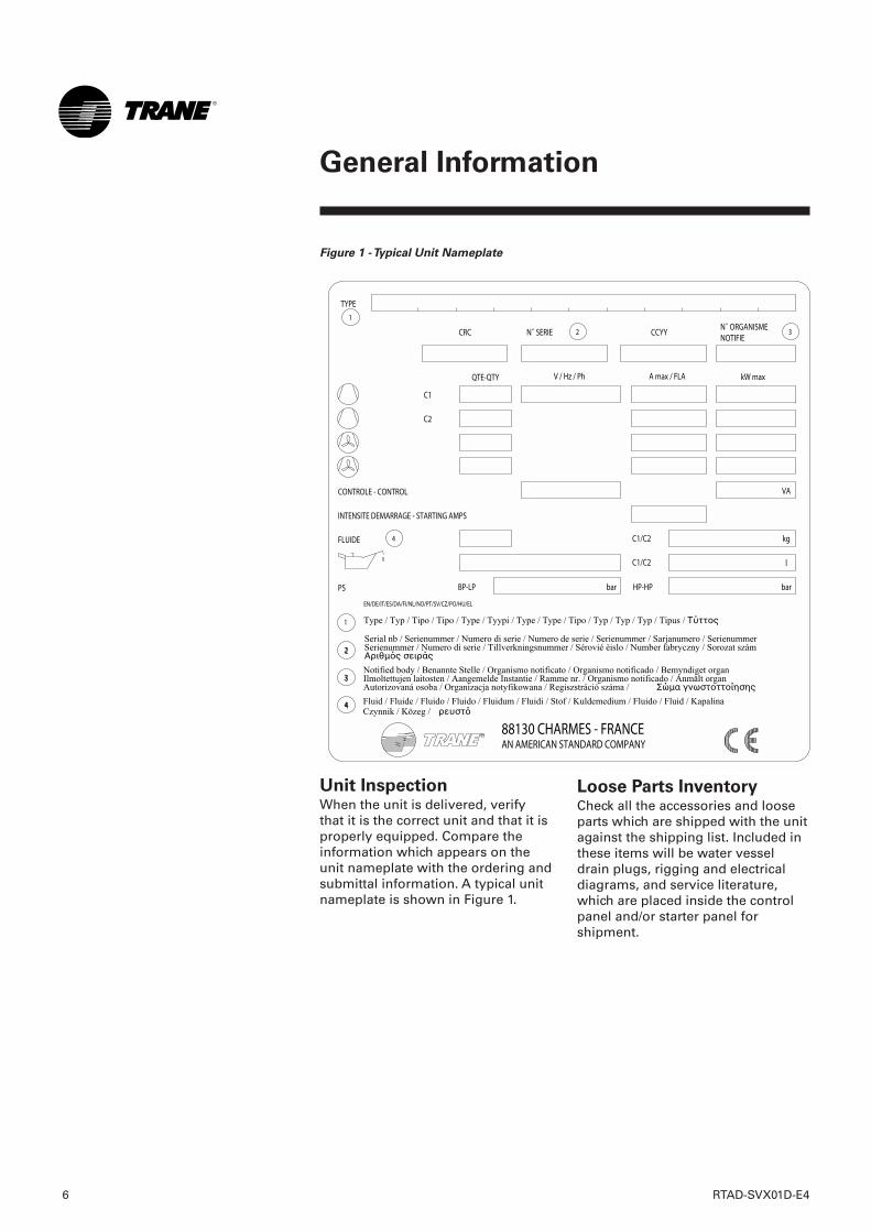
Unit InspectionWhen the unit is delivered, verifythat it is the correct unit and that it isproperly equipped. Compare theinformation which appears on theunit nameplate with the ordering andsubmittal information. A typical unitnameplate is shown in Figure 1.
Loose Parts InventoryCheck all the accessories and looseparts which are shipped with the unitagainst the shipping list. Included inthese items will be water vesseldrain plugs, rigging and electricaldiagrams, and service literature,which are placed inside the controlpanel and/or starter panel forshipment.
Figure 1 - Typical Unit Nameplate
RTAD-SVX01D-E4 7
General Information
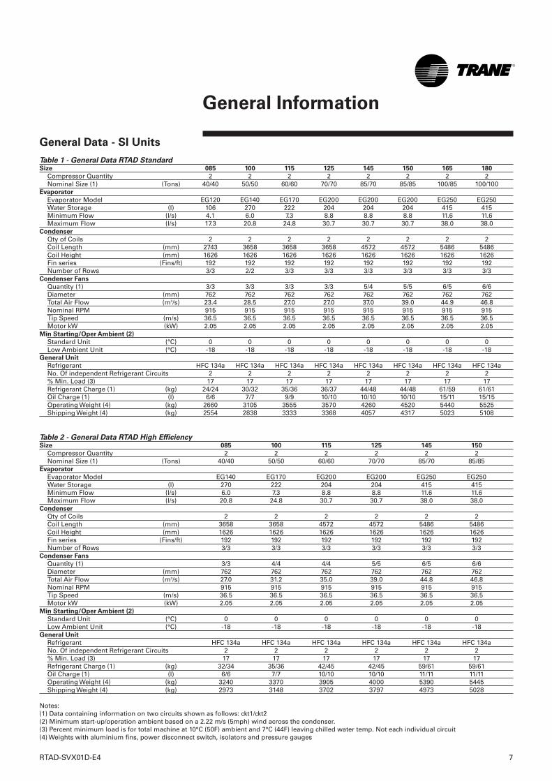
General Data - SI Units
Table 1 - General Data RTAD StandardSize 085 100 115 125 145 150 165 180
Compressor Quantity 2 2 2 2 2 2 2 2Nominal Size (1) (Tons) 40/40 50/50 60/60 70/70 85/70 85/85 100/85 100/100
Evaporator
Evaporator Model EG120 EG140 EG170 EG200 EG200 EG200 EG250 EG250Water Storage (l) 106 270 222 204 204 204 415 415Minimum Flow (l/s) 4.1 6.0 7.3 8.8 8.8 8.8 11.6 11.6Maximum Flow (l/s) 17.3 20.8 24.8 30.7 30.7 30.7 38.0 38.0
Condenser
Qty of Coils 2 2 2 2 2 2 2 2Coil Length (mm) 2743 3658 3658 3658 4572 4572 5486 5486Coil Height (mm) 1626 1626 1626 1626 1626 1626 1626 1626Fin series (Fins/ft) 192 192 192 192 192 192 192 192Number of Rows 3/3 2/2 3/3 3/3 3/3 3/3 3/3 3/3
Condenser Fans
Quantity (1) 3/3 3/3 3/3 3/3 5/4 5/5 6/5 6/6Diameter (mm) 762 762 762 762 762 762 762 762Total Air Flow (m3/s) 23.4 28.5 27.0 27.0 37.0 39.0 44.9 46.8Nominal RPM 915 915 915 915 915 915 915 915Tip Speed (m/s) 36.5 36.5 36.5 36.5 36.5 36.5 36.5 36.5Motor kW (kW) 2.05 2.05 2.05 2.05 2.05 2.05 2.05 2.05
Min Starting/Oper Ambient (2)
Standard Unit (°C) 0 0 0 0 0 0 0 0Low Ambient Unit (°C) -18 -18 -18 -18 -18 -18 -18 -18
General Unit
Refrigerant HFC 134a HFC 134a HFC 134a HFC 134a HFC 134a HFC 134a HFC 134a HFC 134aNo. Of independent Refrigerant Circuits 2 2 2 2 2 2 2 2% Min. Load (3) 17 17 17 17 17 17 17 17Refrigerant Charge (1) (kg) 24/24 30/32 35/36 36/37 44/48 44/48 61/59 61/61Oil Charge (1) (l) 6/6 7/7 9/9 10/10 10/10 10/10 15/11 15/15Operating Weight (4) (kg) 2660 3105 3555 3570 4260 4520 5440 5525Shipping Weight (4) (kg) 2554 2838 3333 3368 4057 4317 5023 5108
Table 2 - General Data RTAD High EfficiencySize 085 100 115 125 145 150
Compressor Quantity 2 2 2 2 2 2Nominal Size (1) (Tons) 40/40 50/50 60/60 70/70 85/70 85/85
Evaporator
Evaporator Model EG140 EG170 EG200 EG200 EG250 EG250Water Storage (l) 270 222 204 204 415 415Minimum Flow (l/s) 6.0 7.3 8.8 8.8 11.6 11.6Maximum Flow (l/s) 20.8 24.8 30.7 30.7 38.0 38.0
Condenser
Qty of Coils 2 2 2 2 2 2Coil Length (mm) 3658 3658 4572 4572 5486 5486Coil Height (mm) 1626 1626 1626 1626 1626 1626Fin series (Fins/ft) 192 192 192 192 192 192Number of Rows 3/3 3/3 3/3 3/3 3/3 3/3
Condenser Fans
Quantity (1) 3/3 4/4 4/4 5/5 6/5 6/6Diameter (mm) 762 762 762 762 762 762Total Air Flow (m3/s) 27.0 31.2 35.0 39.0 44.8 46.8Nominal RPM 915 915 915 915 915 915Tip Speed (m/s) 36.5 36.5 36.5 36.5 36.5 36.5Motor kW (kW) 2.05 2.05 2.05 2.05 2.05 2.05
Min Starting/Oper Ambient (2)
Standard Unit (°C) 0 0 0 0 0 0Low Ambient Unit (°C) -18 -18 -18 -18 -18 -18
General Unit
Refrigerant HFC 134a HFC 134a HFC 134a HFC 134a HFC 134a HFC 134aNo. Of independent Refrigerant Circuits 2 2 2 2 2 2% Min. Load (3) 17 17 17 17 17 17Refrigerant Charge (1) (kg) 32/34 35/36 42/45 42/45 59/61 59/61Oil Charge (1) (l) 6/6 7/7 10/10 10/10 11/11 11/11Operating Weight (4) (kg) 3240 3370 3905 4000 5390 5445Shipping Weight (4) (kg) 2973 3148 3702 3797 4973 5028
Notes:(1) Data containing information on two circuits shown as follows: ckt1/ckt2(2) Minimum start-up/operation ambient based on a 2.22 m/s (5mph) wind across the condenser.(3) Percent minimum load is for total machine at 10°C (50F) ambient and 7°C (44F) leaving chilled water temp. Not each individual circuit(4) Weights with aluminium fins, power disconnect switch, isolators and pressure gauges
8 RTAD-SVX01D-E4
General Information
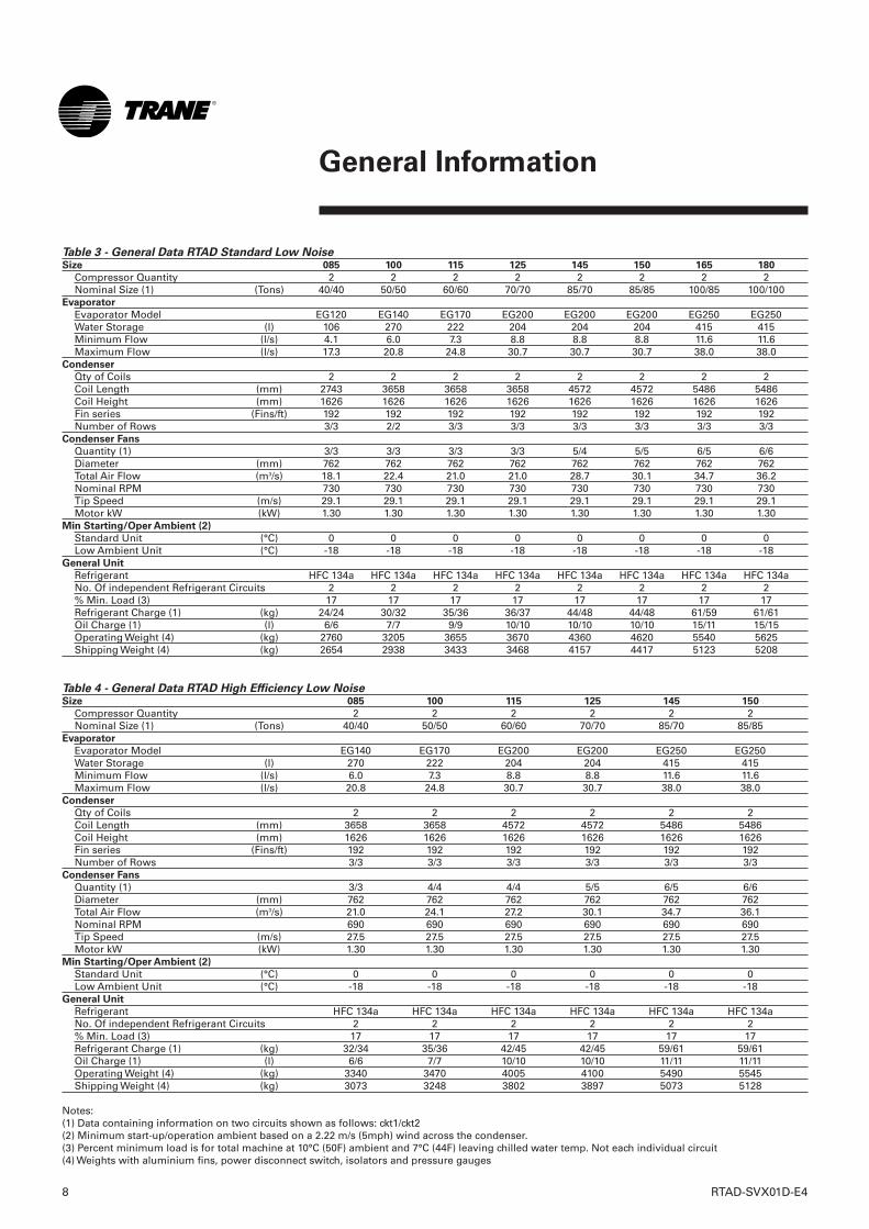
Table 3 - General Data RTAD Standard Low Noise Size 085 100 115 125 145 150 165 180
Compressor Quantity 2 2 2 2 2 2 2 2Nominal Size (1) (Tons) 40/40 50/50 60/60 70/70 85/70 85/85 100/85 100/100
Evaporator
Evaporator Model EG120 EG140 EG170 EG200 EG200 EG200 EG250 EG250Water Storage (l) 106 270 222 204 204 204 415 415Minimum Flow (l/s) 4.1 6.0 7.3 8.8 8.8 8.8 11.6 11.6Maximum Flow (l/s) 17.3 20.8 24.8 30.7 30.7 30.7 38.0 38.0
Condenser
Qty of Coils 2 2 2 2 2 2 2 2Coil Length (mm) 2743 3658 3658 3658 4572 4572 5486 5486Coil Height (mm) 1626 1626 1626 1626 1626 1626 1626 1626Fin series (Fins/ft) 192 192 192 192 192 192 192 192Number of Rows 3/3 2/2 3/3 3/3 3/3 3/3 3/3 3/3
Condenser Fans
Quantity (1) 3/3 3/3 3/3 3/3 5/4 5/5 6/5 6/6Diameter (mm) 762 762 762 762 762 762 762 762Total Air Flow (m3/s) 18.1 22.4 21.0 21.0 28.7 30.1 34.7 36.2Nominal RPM 730 730 730 730 730 730 730 730Tip Speed (m/s) 29.1 29.1 29.1 29.1 29.1 29.1 29.1 29.1Motor kW (kW) 1.30 1.30 1.30 1.30 1.30 1.30 1.30 1.30
Min Starting/Oper Ambient (2)
Standard Unit (°C) 0 0 0 0 0 0 0 0Low Ambient Unit (°C) -18 -18 -18 -18 -18 -18 -18 -18
General Unit
Refrigerant HFC 134a HFC 134a HFC 134a HFC 134a HFC 134a HFC 134a HFC 134a HFC 134aNo. Of independent Refrigerant Circuits 2 2 2 2 2 2 2 2% Min. Load (3) 17 17 17 17 17 17 17 17Refrigerant Charge (1) (kg) 24/24 30/32 35/36 36/37 44/48 44/48 61/59 61/61Oil Charge (1) (l) 6/6 7/7 9/9 10/10 10/10 10/10 15/11 15/15Operating Weight (4) (kg) 2760 3205 3655 3670 4360 4620 5540 5625Shipping Weight (4) (kg) 2654 2938 3433 3468 4157 4417 5123 5208
Table 4 - General Data RTAD High Efficiency Low Noise Size 085 100 115 125 145 150
Compressor Quantity 2 2 2 2 2 2Nominal Size (1) (Tons) 40/40 50/50 60/60 70/70 85/70 85/85
Evaporator
Evaporator Model EG140 EG170 EG200 EG200 EG250 EG250Water Storage (l) 270 222 204 204 415 415Minimum Flow (l/s) 6.0 7.3 8.8 8.8 11.6 11.6Maximum Flow (l/s) 20.8 24.8 30.7 30.7 38.0 38.0
Condenser
Qty of Coils 2 2 2 2 2 2Coil Length (mm) 3658 3658 4572 4572 5486 5486Coil Height (mm) 1626 1626 1626 1626 1626 1626Fin series (Fins/ft) 192 192 192 192 192 192Number of Rows 3/3 3/3 3/3 3/3 3/3 3/3
Condenser Fans
Quantity (1) 3/3 4/4 4/4 5/5 6/5 6/6Diameter (mm) 762 762 762 762 762 762Total Air Flow (m3/s) 21.0 24.1 27.2 30.1 34.7 36.1Nominal RPM 690 690 690 690 690 690Tip Speed (m/s) 27.5 27.5 27.5 27.5 27.5 27.5Motor kW (kW) 1.30 1.30 1.30 1.30 1.30 1.30
Min Starting/Oper Ambient (2)
Standard Unit (°C) 0 0 0 0 0 0Low Ambient Unit (°C) -18 -18 -18 -18 -18 -18
General Unit
Refrigerant HFC 134a HFC 134a HFC 134a HFC 134a HFC 134a HFC 134aNo. Of independent Refrigerant Circuits 2 2 2 2 2 2% Min. Load (3) 17 17 17 17 17 17Refrigerant Charge (1) (kg) 32/34 35/36 42/45 42/45 59/61 59/61Oil Charge (1) (l) 6/6 7/7 10/10 10/10 11/11 11/11Operating Weight (4) (kg) 3340 3470 4005 4100 5490 5545Shipping Weight (4) (kg) 3073 3248 3802 3897 5073 5128
Notes:(1) Data containing information on two circuits shown as follows: ckt1/ckt2(2) Minimum start-up/operation ambient based on a 2.22 m/s (5mph) wind across the condenser.(3) Percent minimum load is for total machine at 10°C (50F) ambient and 7°C (44F) leaving chilled water temp. Not each individual circuit(4) Weights with aluminium fins, power disconnect switch, isolators and pressure gauges

RTAD-SVX01D-E4 9
General Information
Table 5 - General Data RTAD Standard Low Noise with Night Noise Set Back optionSize 085 100 115 125 145 150 165 180
Compressor Quantity 2 2 2 2 2 2 2 2Nominal Size (1) (Tons) 40/40 50/50 60/60 70/70 85/70 85/85 100/85 100/100
Evaporator
Evaporator Model EG120 EG140 EG170 EG200 EG200 EG200 EG250 EG250Water Storage (l) 106 270 222 204 204 204 415 415Minimum Flow (l/s) 4.1 6.0 7.3 8.8 8.8 8.8 11.6 11.6Maximum Flow (l/s) 17.3 20.8 24.8 30.7 30.7 30.7 38.0 38.0
Condenser
Qty of Coils 2 2 2 2 2 2 2 2Coil Length (mm) 2743 3658 3658 3658 4572 4572 5486 5486Coil Height (mm) 1626 1626 1626 1626 1626 1626 1626 1626Fin series (Fins/ft) 192 192 192 192 192 192 192 192Number of Rows 3/3 2/2 3/3 3/3 3/3 3/3 3/3 3/3
Condenser Fans
Quantity (1) 2/2 3/3 3/3 3/3 4/4 4/4 5/5 5/5Diameter (mm) 762 762 762 762 762 762 762 762Total Air Flow (m3/s) 13.4 20.5 19.3 19.3 25.0 25.0 30.7 30.7Nominal RPM 550 550 550 550 550 550 550 550Tip Speed (m/s) 21.9 21.9 21.9 21.9 21.9 21.9 21.9 21.9Motor kW (kW) 1.05 1.05 1.05 1.05 1.05 1.05 1.05 1.05
Min Starting/Oper Ambient (2)
Standard Unit (°C) 0 0 0 0 0 0 0 0Low Ambient Unit (°C) -18 -18 -18 -18 -18 -18 -18 -18
General Unit
Refrigerant HFC 134a HFC 134a HFC 134a HFC 134a HFC 134a HFC 134a HFC 134a HFC 134aNo. Of independent Refrigerant Circuits 2 2 2 2 2 2 2 2% Min. Load (3) 17 17 17 17 17 17 17 17Refrigerant Charge (1) (kg) 24/24 30/32 35/36 36/37 44/48 44/48 61/59 61/61Oil Charge (1) (l) 6/6 7/7 9/9 10/10 10/10 10/10 15/11 15/15Operating Weight (4) (kg) 2660 3205 3655 3670 4310 4520 5490 5525Shipping Weight (4) (kg) 2554 2938 3433 3468 4107 4317 5073 5108
Table 6 - General Data RTAD High Efficiency Low Noise with Night Noise Set Back optionSize 085 100 115 125 145 150
Compressor Quantity 2 2 2 2 2 2Nominal Size (1) (Tons) 40/40 50/50 60/60 70/70 85/70 85/85
Evaporator
Evaporator Model EG140 EG170 EG200 EG200 EG250 EG250Water Storage (l) 270 222 204 204 415 415Minimum Flow (l/s) 6.0 7.3 8.8 8.8 11.6 11.6Maximum Flow (l/s) 20.8 24.8 30.7 30.7 38.0 38.0
Condenser
Qty of Coils 2 2 2 2 2 2Coil Length (mm) 3658 3658 4572 4572 5486 5486Coil Height (mm) 1626 1626 1626 1626 1626 1626Fin series (Fins/ft) 192 192 192 192 192 192Number of Rows 3/3 3/3 3/3 3/3 3/3 3/3
Condenser Fans
Quantity (1) 3/3 3/3 4/4 4/4 5/5 5/5Diameter (mm) 762 762 762 762 762 762Total Air Flow (m3/s) 19.2 19.2 24.9 25.0 30.6 30.6Nominal RPM 550 550 550 550 550 550Tip Speed (m/s) 21.9 21.9 21.9 21.9 21.9 21.9Motor kW (kW) 1.05 1.05 1.05 1.05 1.05 1.05
Min Starting/Oper Ambient (2)
Standard Unit (°C) 0 0 0 0 0 0Low Ambient Unit (°C) -18 -18 -18 -18 -18 -18
General Unit
Refrigerant HFC 134a HFC 134a HFC 134a HFC 134a HFC 134a HFC 134aNo. Of independent Refrigerant Circuits 2 2 2 2 2 2% Min. Load (3) 17 17 17 17 17 17Refrigerant Charge (1) (kg) 32/34 35/36 42/45 42/45 59/61 59/61Oil Charge (1) (l) 6/6 7/7 10/10 10/10 11/11 11/11Operating Weight (4) (kg) 3340 3370 4005 4000 5440 5445Shipping Weight (4) (kg) 3073 3148 3802 3797 5023 5028
Notes:(1) Data containing information on two circuits shown as follows: ckt1/ckt2(2) Minimum start-up/operation ambient based on a 2.22 m/s (5mph) wind across the condenser.(3) Percent minimum load is for total machine at 10°C (50F) ambient and 7°C (44F) leaving chilled water temp. Not each individual circuit(4) Weights with aluminium fins, power disconnect switch, isolators and pressure gauges
10 RTAD-SVX01D-E4
General Information
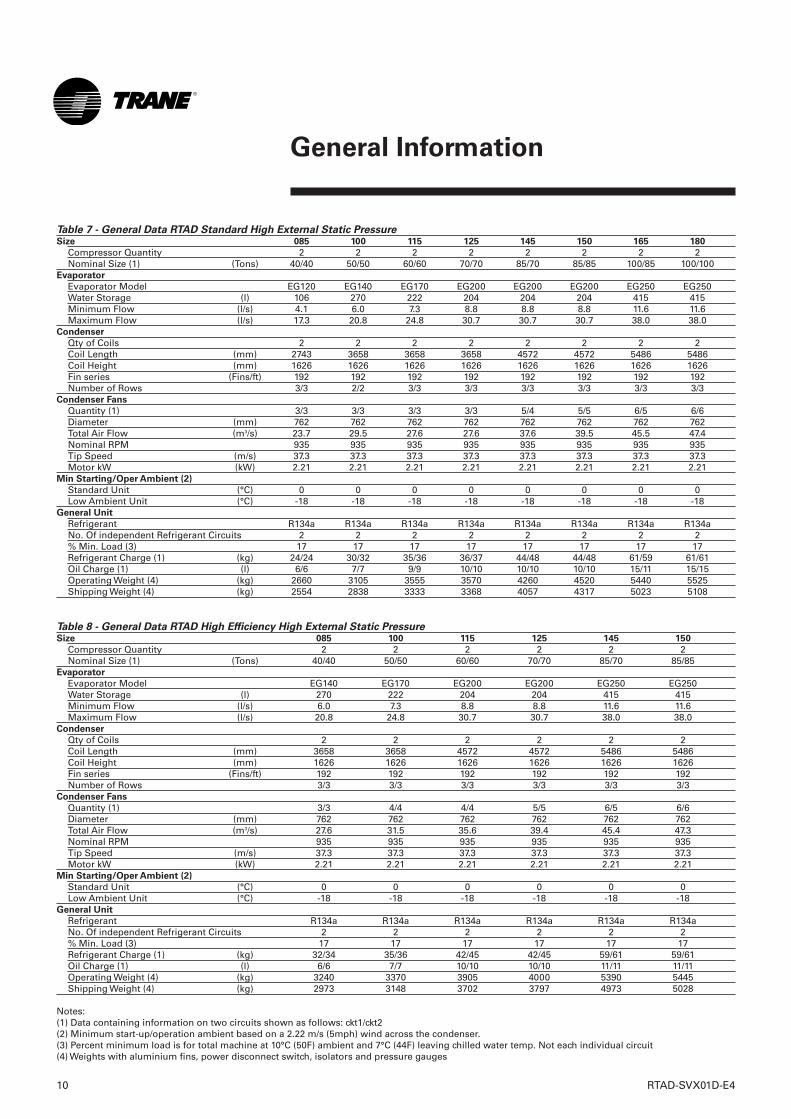
Table 7 - General Data RTAD Standard High External Static PressureSize 085 100 115 125 145 150 165 180
Compressor Quantity 2 2 2 2 2 2 2 2Nominal Size (1) (Tons) 40/40 50/50 60/60 70/70 85/70 85/85 100/85 100/100
Evaporator
Evaporator Model EG120 EG140 EG170 EG200 EG200 EG200 EG250 EG250Water Storage (l) 106 270 222 204 204 204 415 415Minimum Flow (l/s) 4.1 6.0 7.3 8.8 8.8 8.8 11.6 11.6Maximum Flow (l/s) 17.3 20.8 24.8 30.7 30.7 30.7 38.0 38.0
Condenser
Qty of Coils 2 2 2 2 2 2 2 2Coil Length (mm) 2743 3658 3658 3658 4572 4572 5486 5486Coil Height (mm) 1626 1626 1626 1626 1626 1626 1626 1626Fin series (Fins/ft) 192 192 192 192 192 192 192 192Number of Rows 3/3 2/2 3/3 3/3 3/3 3/3 3/3 3/3
Condenser Fans
Quantity (1) 3/3 3/3 3/3 3/3 5/4 5/5 6/5 6/6Diameter (mm) 762 762 762 762 762 762 762 762Total Air Flow (m3/s) 23.7 29.5 27.6 27.6 37.6 39.5 45.5 47.4Nominal RPM 935 935 935 935 935 935 935 935Tip Speed (m/s) 37.3 37.3 37.3 37.3 37.3 37.3 37.3 37.3Motor kW (kW) 2.21 2.21 2.21 2.21 2.21 2.21 2.21 2.21
Min Starting/Oper Ambient (2)
Standard Unit (°C) 0 0 0 0 0 0 0 0Low Ambient Unit (°C) -18 -18 -18 -18 -18 -18 -18 -18
General Unit
Refrigerant R134a R134a R134a R134a R134a R134a R134a R134aNo. Of independent Refrigerant Circuits 2 2 2 2 2 2 2 2% Min. Load (3) 17 17 17 17 17 17 17 17Refrigerant Charge (1) (kg) 24/24 30/32 35/36 36/37 44/48 44/48 61/59 61/61Oil Charge (1) (l) 6/6 7/7 9/9 10/10 10/10 10/10 15/11 15/15Operating Weight (4) (kg) 2660 3105 3555 3570 4260 4520 5440 5525Shipping Weight (4) (kg) 2554 2838 3333 3368 4057 4317 5023 5108
Table 8 - General Data RTAD High Efficiency High External Static PressureSize 085 100 115 125 145 150
Compressor Quantity 2 2 2 2 2 2Nominal Size (1) (Tons) 40/40 50/50 60/60 70/70 85/70 85/85
Evaporator
Evaporator Model EG140 EG170 EG200 EG200 EG250 EG250Water Storage (l) 270 222 204 204 415 415Minimum Flow (l/s) 6.0 7.3 8.8 8.8 11.6 11.6Maximum Flow (l/s) 20.8 24.8 30.7 30.7 38.0 38.0
Condenser
Qty of Coils 2 2 2 2 2 2Coil Length (mm) 3658 3658 4572 4572 5486 5486Coil Height (mm) 1626 1626 1626 1626 1626 1626Fin series (Fins/ft) 192 192 192 192 192 192Number of Rows 3/3 3/3 3/3 3/3 3/3 3/3
Condenser Fans
Quantity (1) 3/3 4/4 4/4 5/5 6/5 6/6Diameter (mm) 762 762 762 762 762 762Total Air Flow (m3/s) 27.6 31.5 35.6 39.4 45.4 47.3Nominal RPM 935 935 935 935 935 935Tip Speed (m/s) 37.3 37.3 37.3 37.3 37.3 37.3Motor kW (kW) 2.21 2.21 2.21 2.21 2.21 2.21
Min Starting/Oper Ambient (2)
Standard Unit (°C) 0 0 0 0 0 0Low Ambient Unit (°C) -18 -18 -18 -18 -18 -18
General Unit
Refrigerant R134a R134a R134a R134a R134a R134aNo. Of independent Refrigerant Circuits 2 2 2 2 2 2% Min. Load (3) 17 17 17 17 17 17Refrigerant Charge (1) (kg) 32/34 35/36 42/45 42/45 59/61 59/61Oil Charge (1) (l) 6/6 7/7 10/10 10/10 11/11 11/11Operating Weight (4) (kg) 3240 3370 3905 4000 5390 5445Shipping Weight (4) (kg) 2973 3148 3702 3797 4973 5028
Notes:(1) Data containing information on two circuits shown as follows: ckt1/ckt2(2) Minimum start-up/operation ambient based on a 2.22 m/s (5mph) wind across the condenser.(3) Percent minimum load is for total machine at 10°C (50F) ambient and 7°C (44F) leaving chilled water temp. Not each individual circuit(4) Weights with aluminium fins, power disconnect switch, isolators and pressure gauges
RTAD-SVX01D-E4 11
General Information
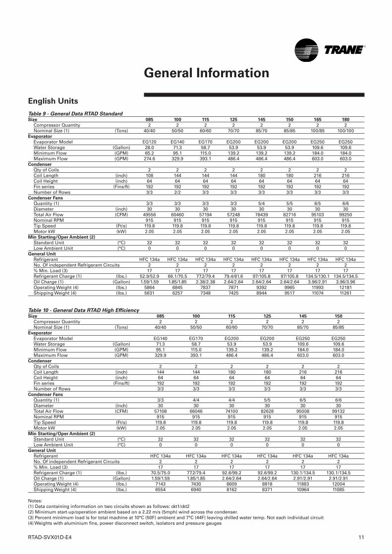
English Units
Table 9 - General Data RTAD StandardSize 085 100 115 125 145 150 165 180
Compressor Quantity 2 2 2 2 2 2 2 2Nominal Size (1) (Tons) 40/40 50/50 60/60 70/70 85/70 85/85 100/85 100/100
Evaporator
Evaporator Model EG120 EG140 EG170 EG200 EG200 EG200 EG250 EG250Water Storage (Gallon) 28.0 71.3 58.7 53.9 53.9 53.9 109.6 109.6Minimum Flow (GPM) 65.2 95.1 115.0 139.2 139.2 139.2 184.0 184.0Maximum Flow (GPM) 274.6 329.9 393.1 486.4 486.4 486.4 603.0 603.0
Condenser
Qty of Coils 2 2 2 2 2 2 2 2Coil Length (inch) 108 144 144 144 180 180 216 216Coil Height (inch) 64 64 64 64 64 64 64 64Fin series (Fins/ft) 192 192 192 192 192 192 192 192Number of Rows 3/3 2/2 3/3 3/3 3/3 3/3 3/3 3/3
Condenser Fans
Quantity (1) 3/3 3/3 3/3 3/3 5/4 5/5 6/5 6/6Diameter (inch) 30 30 30 30 30 30 30 30Total Air Flow (CFM) 49556 60460 57194 57248 78439 82716 95103 99250Nominal RPM 915 915 915 915 915 915 915 915Tip Speed (Ft/s) 119.8 119.8 119.8 119.8 119.8 119.8 119.8 119.8Motor kW (kW) 2.05 2.05 2.05 2.05 2.05 2.05 2.05 2.05
Min Starting/Oper Ambient (2)
Standard Unit (°C) 32 32 32 32 32 32 32 32Low Ambient Unit (°C) 0 0 0 0 0 0 0 0
General Unit
Refrigerant HFC 134a HFC 134a HFC 134a HFC 134a HFC 134a HFC 134a HFC 134a HFC 134aNo. Of independent Refrigerant Circuits 2 2 2 2 2 2 2 2% Min. Load (3) 17 17 17 17 17 17 17 17Refrigerant Charge (1) (lbs.) 52.9/52.9 66.1/70.5 77.2/79.4 79.4/81.6 97/105.8 97/105.8 134.5/130.1 134.5/134.5Oil Charge (1) (Gallon) 1.59/1.59 1.85/1.85 2.38/2.38 2.64/2.64 2.64/2.64 2.64/2.64 3.96/2.91 3.96/3.96Operating Weight (4) (lbs.) 5864 6845 7837 7871 9392 9965 11993 12181Shipping Weight (4) (lbs.) 5631 6257 7348 7425 8944 9517 11074 11261
Table 10 - General Data RTAD High EfficiencySize 085 100 115 125 145 150
Compressor Quantity 2 2 2 2 2 2Nominal Size (1) (Tons) 40/40 50/50 60/60 70/70 85/70 85/85
Evaporator
Evaporator Model EG140 EG170 EG200 EG200 EG250 EG250Water Storage (Gallon) 71.3 58.7 53.9 53.9 109.6 109.6Minimum Flow (GPM) 95.1 115.0 139.2 139.2 184.0 184.0Maximum Flow (GPM) 329.9 393.1 486.4 486.4 603.0 603.0
Condenser
Qty of Coils 2 2 2 2 2 2Coil Length (inch) 144 144 180 180 216 216Coil Height (inch) 64 64 64 64 64 64Fin series (Fins/ft) 192 192 192 192 192 192Number of Rows 3/3 3/3 3/3 3/3 3/3 3/3
Condenser Fans
Quantity (1) 3/3 4/4 4/4 5/5 6/5 6/6Diameter (inch) 30 30 30 30 30 30Total Air Flow (CFM) 57108 66046 74100 82628 95008 99132Nominal RPM 915 915 915 915 915 915Tip Speed (Ft/s) 119.8 119.8 119.8 119.8 119.8 119.8Motor kW (kW) 2.05 2.05 2.05 2.05 2.05 2.05
Min Starting/Oper Ambient (2)
Standard Unit (°C) 32 32 32 32 32 32Low Ambient Unit (°C) 0 0 0 0 0 0
General Unit
Refrigerant HFC 134a HFC 134a HFC 134a HFC 134a HFC 134a HFC 134aNo. Of independent Refrigerant Circuits 2 2 2 2 2 2% Min. Load (3) 17 17 17 17 17 17Refrigerant Charge (1) (lbs.) 70.5/75.0 77.2/79.4 92.6/99.2 92.6/99.2 130.1/134.5 130.1/134.5Oil Charge (1) (Gallon) 1.59/1.59 1.85/1.85 2.64/2.64 2.64/2.64 2.91/2.91 2.91/2.91Operating Weight (4) (lbs.) 7143 7430 8609 8818 11883 12004Shipping Weight (4) (lbs.) 6554 6940 8162 8371 10964 11085
Notes:(1) Data containing information on two circuits shown as follows: ckt1/ckt2(2) Minimum start-up/operation ambient based on a 2.22 m/s (5mph) wind across the condenser.(3) Percent minimum load is for total machine at 10°C (50F) ambient and 7°C (44F) leaving chilled water temp. Not each individual circuit(4) Weights with aluminium fins, power disconnect switch, isolators and pressure gauges
12 RTAD-SVX01D-E4
General Information
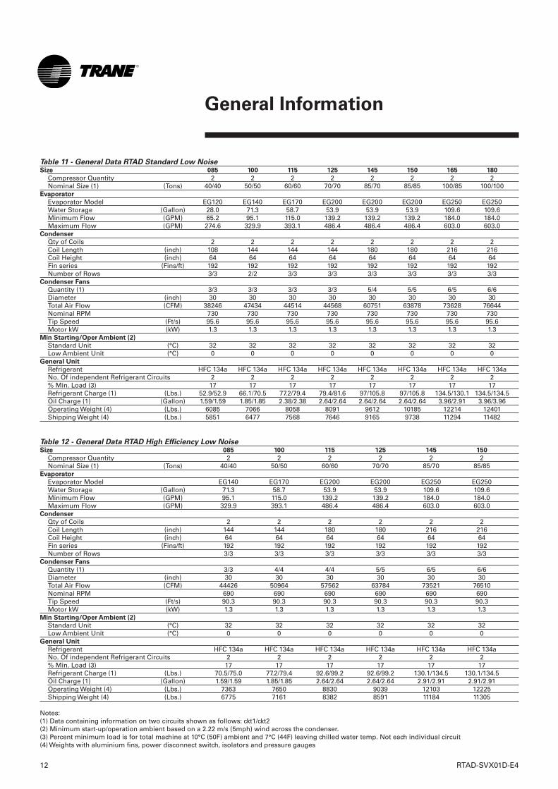
Table 11 - General Data RTAD Standard Low Noise Size 085 100 115 125 145 150 165 180
Compressor Quantity 2 2 2 2 2 2 2 2Nominal Size (1) (Tons) 40/40 50/50 60/60 70/70 85/70 85/85 100/85 100/100
Evaporator
Evaporator Model EG120 EG140 EG170 EG200 EG200 EG200 EG250 EG250Water Storage (Gallon) 28.0 71.3 58.7 53.9 53.9 53.9 109.6 109.6Minimum Flow (GPM) 65.2 95.1 115.0 139.2 139.2 139.2 184.0 184.0Maximum Flow (GPM) 274.6 329.9 393.1 486.4 486.4 486.4 603.0 603.0
Condenser
Qty of Coils 2 2 2 2 2 2 2 2Coil Length (inch) 108 144 144 144 180 180 216 216Coil Height (inch) 64 64 64 64 64 64 64 64Fin series (Fins/ft) 192 192 192 192 192 192 192 192Number of Rows 3/3 2/2 3/3 3/3 3/3 3/3 3/3 3/3
Condenser Fans
Quantity (1) 3/3 3/3 3/3 3/3 5/4 5/5 6/5 6/6Diameter (inch) 30 30 30 30 30 30 30 30Total Air Flow (CFM) 38246 47434 44514 44568 60751 63878 73628 76644Nominal RPM 730 730 730 730 730 730 730 730Tip Speed (Ft/s) 95.6 95.6 95.6 95.6 95.6 95.6 95.6 95.6Motor kW (kW) 1.3 1.3 1.3 1.3 1.3 1.3 1.3 1.3
Min Starting/Oper Ambient (2)
Standard Unit (°C) 32 32 32 32 32 32 32 32Low Ambient Unit (°C) 0 0 0 0 0 0 0 0
General Unit
Refrigerant HFC 134a HFC 134a HFC 134a HFC 134a HFC 134a HFC 134a HFC 134a HFC 134aNo. Of independent Refrigerant Circuits 2 2 2 2 2 2 2 2% Min. Load (3) 17 17 17 17 17 17 17 17Refrigerant Charge (1) (Lbs.) 52.9/52.9 66.1/70.5 77.2/79.4 79.4/81.6 97/105.8 97/105.8 134.5/130.1 134.5/134.5Oil Charge (1) (Gallon) 1.59/1.59 1.85/1.85 2.38/2.38 2.64/2.64 2.64/2.64 2.64/2.64 3.96/2.91 3.96/3.96Operating Weight (4) (Lbs.) 6085 7066 8058 8091 9612 10185 12214 12401Shipping Weight (4) (Lbs.) 5851 6477 7568 7646 9165 9738 11294 11482
Table 12 - General Data RTAD High Efficiency Low NoiseSize 085 100 115 125 145 150
Compressor Quantity 2 2 2 2 2 2Nominal Size (1) (Tons) 40/40 50/50 60/60 70/70 85/70 85/85
Evaporator
Evaporator Model EG140 EG170 EG200 EG200 EG250 EG250Water Storage (Gallon) 71.3 58.7 53.9 53.9 109.6 109.6Minimum Flow (GPM) 95.1 115.0 139.2 139.2 184.0 184.0Maximum Flow (GPM) 329.9 393.1 486.4 486.4 603.0 603.0
Condenser
Qty of Coils 2 2 2 2 2 2Coil Length (inch) 144 144 180 180 216 216Coil Height (inch) 64 64 64 64 64 64Fin series (Fins/ft) 192 192 192 192 192 192Number of Rows 3/3 3/3 3/3 3/3 3/3 3/3
Condenser Fans
Quantity (1) 3/3 4/4 4/4 5/5 6/5 6/6Diameter (inch) 30 30 30 30 30 30Total Air Flow (CFM) 44426 50964 57562 63784 73521 76510Nominal RPM 690 690 690 690 690 690Tip Speed (Ft/s) 90.3 90.3 90.3 90.3 90.3 90.3Motor kW (kW) 1.3 1.3 1.3 1.3 1.3 1.3
Min Starting/Oper Ambient (2)
Standard Unit (°C) 32 32 32 32 32 32Low Ambient Unit (°C) 0 0 0 0 0 0
General Unit
Refrigerant HFC 134a HFC 134a HFC 134a HFC 134a HFC 134a HFC 134aNo. Of independent Refrigerant Circuits 2 2 2 2 2 2% Min. Load (3) 17 17 17 17 17 17Refrigerant Charge (1) (Lbs.) 70.5/75.0 77.2/79.4 92.6/99.2 92.6/99.2 130.1/134.5 130.1/134.5Oil Charge (1) (Gallon) 1.59/1.59 1.85/1.85 2.64/2.64 2.64/2.64 2.91/2.91 2.91/2.91Operating Weight (4) (Lbs.) 7363 7650 8830 9039 12103 12225Shipping Weight (4) (Lbs.) 6775 7161 8382 8591 11184 11305
Notes:(1) Data containing information on two circuits shown as follows: ckt1/ckt2(2) Minimum start-up/operation ambient based on a 2.22 m/s (5mph) wind across the condenser.(3) Percent minimum load is for total machine at 10°C (50F) ambient and 7°C (44F) leaving chilled water temp. Not each individual circuit(4) Weights with aluminium fins, power disconnect switch, isolators and pressure gauges
RTAD-SVX01D-E4 13
General Information
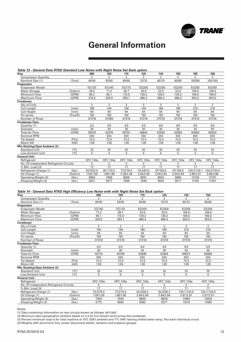
Table 13 - General Data RTAD Standard Low Noise with Night Noise Set Back optionSize 085 100 115 125 145 150 165 180
Compressor Quantity 2 2 2 2 2 2 2 2Nominal Size (1) (Tons) 40/40 50/50 60/60 70/70 85/70 85/85 100/85 100/100
Evaporator
Evaporator Model EG120 EG140 EG170 EG200 EG200 EG200 EG250 EG250Water Storage (Gallon) 28.0 71.3 58.7 53.9 53.9 53.9 109.6 109.6Minimum Flow (GPM) 65.2 95.1 115.0 139.2 139.2 139.2 184.0 184.0Maximum Flow (GPM) 274.6 329.9 393.1 486.4 486.4 486.4 603.0 603.0
Condenser
Qty of Coils 2 2 2 2 2 2 2 2Coil Length (inch) 108 144 144 144 180 180 216 216Coil Height (inch) 64 64 64 64 64 64 64 64Fin series (Fins/ft) 192 192 192 192 192 192 192 192Number of Rows 37318 37289 37318 37318 37318 37318 37318 37318
Condenser Fans
Quantity (1) 2/2 3/3 3/3 3/3 4/4 4/4 5/5 5/5Diameter (inch) 30 30 30 30 30 30 30 30Total Air Flow (CFM) 28479 43376 40791 40842 52929 52962 64956 65000Nominal RPM 550 550 550 550 550 550 550 550Tip Speed (Ft/s) 72.0 72.0 72.0 72.0 72.0 72.0 72.0 72.0Motor kW (kW) 1.05 1.05 1.05 1.05 1.05 1.05 1.05 1.05
Min Starting/Oper Ambient (2)
Standard Unit (°C) 32 32 32 32 32 32 32 32Low Ambient Unit (°C) 0 0 0 0 0 0 0 0
General Unit
Refrigerant HFC 134a HFC 134a HFC 134a HFC 134a HFC 134a HFC 134a HFC 134a HFC 134aNo. Of independent Refrigerant Circuits 2 2 2 2 2 2 2 2% Min. Load (3) 17 17 17 17 17 17 17 17Refrigerant Charge (1) (lbs.) 52.9/52.9 66.1/70.5 77.2/79.4 79.4/81.6 97/105.8 97/105.8 134.5/130.1 134.5/134.5Oil Charge (1) (Gallon) 1.59/1.59 1.85/1.85 2.38/2.38 2.64/2.64 2.64/2.64 2.64/2.64 3.96/2.91 3.96/3.96Operating Weight (4) (lbs.) 5864 7066 8058 8091 9502 9965 12103 12181Shipping Weight (4) (lbs.) 5631 6477 7568 7646 9054 9517 11184 11261
Table 14 - General Data RTAD High Efficiency Low Noise with with Night Noise Set Back optionSize 085 100 115 125 145 150
Compressor Quantity 2 2 2 2 2 2Nominal Size (1) (Tons) 40/40 50/50 60/60 70/70 85/70 85/85
Evaporator
Evaporator Model EG140 EG170 EG200 EG200 EG250 EG250Water Storage (Gallon) 71.3 58.7 53.9 53.9 109.6 109.6Minimum Flow (GPM) 95.1 115.0 139.2 139.2 184.0 184.0Maximum Flow (GPM) 329.9 393.1 486.4 486.4 603.0 603.0
Condenser
Qty of Coils 2 2 2 2 2 2Coil Length (inch) 144 144 180 180 216 216Coil Height (inch) 64 64 64 64 64 64Fin series (Fins/ft) 192 192 192 192 192 192Number of Rows 37318 37318 37318 37318 37318 37318
Condenser Fans
Quantity (1) 3/3 3/3 4/4 4/4 5/5 5/5Diameter (inch) 30 30 30 30 30 30Total Air Flow (CFM) 40710 40746 52846 52904 64872 64906Nominal RPM 550 550 550 550 550 550Tip Speed (Ft/s) 72.0 72.0 72.0 72.0 72.0 72.0Motor kW (kW) 1.05 1.05 1.05 1.05 1.05 1.05
Min Starting/Oper Ambient (2)
Standard Unit (°C) 32 32 32 32 32 32Low Ambient Unit (°C) 0 0 0 0 0 0
General Unit
Refrigerant HFC 134a HFC 134a HFC 134a HFC 134a HFC 134a HFC 134aNo. Of independent Refrigerant Circuits 2 2 2 2 2 2% Min. Load (3) 17 17 17 17 17 17Refrigerant Charge (1) (lbs.) 70.5/75.0 77.2/79.4 92.6/99.2 92.6/99.2 130.1/134.5 130.1/134.5Oil Charge (1) (Gallon) 1.59/1.59 1.85/1.85 2.64/2.64 2.64/2.64 2.91/2.91 2.91/2.91Operating Weight (4) (lbs.) 7363 7430 8830 8818 11993 12004Shipping Weight (4) (lbs.) 6775 6940 8382 8371 11074 11085
Notes:(1) Data containing information on two circuits shown as follows: ckt1/ckt2(2) Minimum start-up/operation ambient based on a 2.22 m/s (5mph) wind across the condenser.(3) Percent minimum load is for total machine at 10°C (50F) ambient and 7°C (44F) leaving chilled water temp. Not each individual circuit(4) Weights with aluminium fins, power disconnect switch, isolators and pressure gauges
14 RTAD-SVX01D-E4
General Information
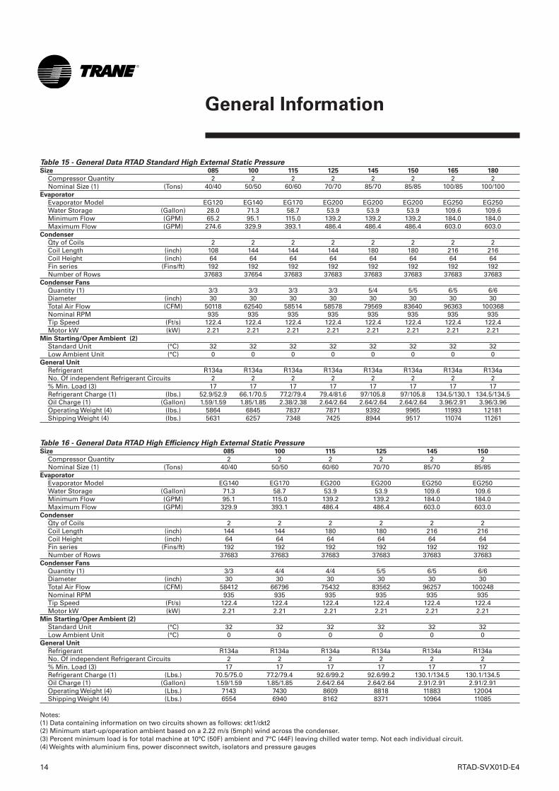
Table 15 - General Data RTAD Standard High External Static PressureSize 085 100 115 125 145 150 165 180
Compressor Quantity 2 2 2 2 2 2 2 2Nominal Size (1) (Tons) 40/40 50/50 60/60 70/70 85/70 85/85 100/85 100/100
Evaporator
Evaporator Model EG120 EG140 EG170 EG200 EG200 EG200 EG250 EG250Water Storage (Gallon) 28.0 71.3 58.7 53.9 53.9 53.9 109.6 109.6Minimum Flow (GPM) 65.2 95.1 115.0 139.2 139.2 139.2 184.0 184.0Maximum Flow (GPM) 274.6 329.9 393.1 486.4 486.4 486.4 603.0 603.0
Condenser
Qty of Coils 2 2 2 2 2 2 2 2Coil Length (inch) 108 144 144 144 180 180 216 216Coil Height (inch) 64 64 64 64 64 64 64 64Fin series (Fins/ft) 192 192 192 192 192 192 192 192Number of Rows 37683 37654 37683 37683 37683 37683 37683 37683
Condenser Fans
Quantity (1) 3/3 3/3 3/3 3/3 5/4 5/5 6/5 6/6Diameter (inch) 30 30 30 30 30 30 30 30Total Air Flow (CFM) 50118 62540 58514 58578 79569 83640 96363 100368Nominal RPM 935 935 935 935 935 935 935 935Tip Speed (Ft/s) 122.4 122.4 122.4 122.4 122.4 122.4 122.4 122.4Motor kW (kW) 2.21 2.21 2.21 2.21 2.21 2.21 2.21 2.21
Min Starting/Oper Ambient (2)
Standard Unit (°C) 32 32 32 32 32 32 32 32Low Ambient Unit (°C) 0 0 0 0 0 0 0 0
General Unit
Refrigerant R134a R134a R134a R134a R134a R134a R134a R134aNo. Of independent Refrigerant Circuits 2 2 2 2 2 2 2 2% Min. Load (3) 17 17 17 17 17 17 17 17Refrigerant Charge (1) (lbs.) 52.9/52.9 66.1/70.5 77.2/79.4 79.4/81.6 97/105.8 97/105.8 134.5/130.1 134.5/134.5Oil Charge (1) (Gallon) 1.59/1.59 1.85/1.85 2.38/2.38 2.64/2.64 2.64/2.64 2.64/2.64 3.96/2.91 3.96/3.96Operating Weight (4) (lbs.) 5864 6845 7837 7871 9392 9965 11993 12181Shipping Weight (4) (lbs.) 5631 6257 7348 7425 8944 9517 11074 11261
Table 16 - General Data RTAD High Efficiency High External Static PressureSize 085 100 115 125 145 150
Compressor Quantity 2 2 2 2 2 2Nominal Size (1) (Tons) 40/40 50/50 60/60 70/70 85/70 85/85
Evaporator
Evaporator Model EG140 EG170 EG200 EG200 EG250 EG250Water Storage (Gallon) 71.3 58.7 53.9 53.9 109.6 109.6Minimum Flow (GPM) 95.1 115.0 139.2 139.2 184.0 184.0Maximum Flow (GPM) 329.9 393.1 486.4 486.4 603.0 603.0
Condenser
Qty of Coils 2 2 2 2 2 2Coil Length (inch) 144 144 180 180 216 216Coil Height (inch) 64 64 64 64 64 64Fin series (Fins/ft) 192 192 192 192 192 192Number of Rows 37683 37683 37683 37683 37683 37683
Condenser Fans
Quantity (1) 3/3 4/4 4/4 5/5 6/5 6/6Diameter (inch) 30 30 30 30 30 30Total Air Flow (CFM) 58412 66796 75432 83562 96257 100248Nominal RPM 935 935 935 935 935 935Tip Speed (Ft/s) 122.4 122.4 122.4 122.4 122.4 122.4Motor kW (kW) 2.21 2.21 2.21 2.21 2.21 2.21
Min Starting/Oper Ambient (2)
Standard Unit (°C) 32 32 32 32 32 32Low Ambient Unit (°C) 0 0 0 0 0 0
General Unit
Refrigerant R134a R134a R134a R134a R134a R134aNo. Of independent Refrigerant Circuits 2 2 2 2 2 2% Min. Load (3) 17 17 17 17 17 17Refrigerant Charge (1) (Lbs.) 70.5/75.0 77.2/79.4 92.6/99.2 92.6/99.2 130.1/134.5 130.1/134.5Oil Charge (1) (Gallon) 1.59/1.59 1.85/1.85 2.64/2.64 2.64/2.64 2.91/2.91 2.91/2.91Operating Weight (4) (Lbs.) 7143 7430 8609 8818 11883 12004Shipping Weight (4) (Lbs.) 6554 6940 8162 8371 10964 11085
Notes:(1) Data containing information on two circuits shown as follows: ckt1/ckt2(2) Minimum start-up/operation ambient based on a 2.22 m/s (5mph) wind across the condenser.(3) Percent minimum load is for total machine at 10°C (50F) ambient and 7°C (44F) leaving chilled water temp. Not each individual circuit.(4) Weights with aluminium fins, power disconnect switch, isolators and pressure gauges
RTAD-SVX01D-E4 15
General Information
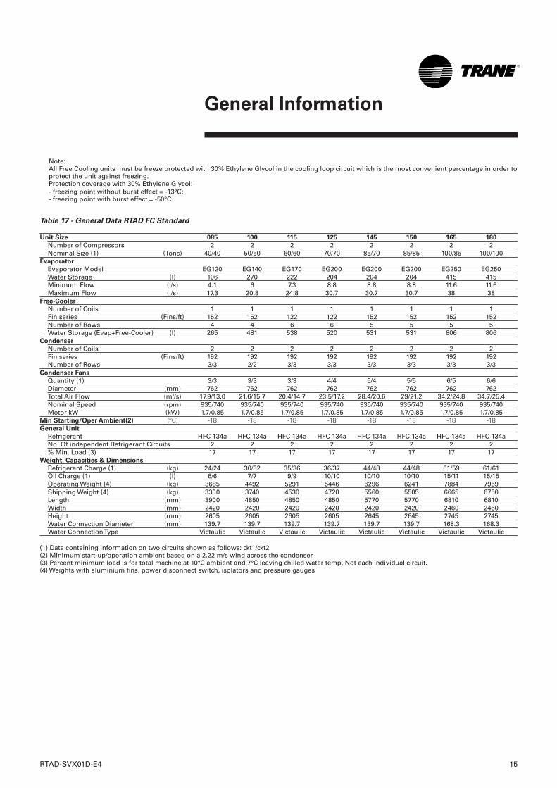
Table 17 - General Data RTAD FC Standard
Unit Size 085 100 115 125 145 150 165 180
Number of Compressors 2 2 2 2 2 2 2 2Nominal Size (1) (Tons) 40/40 50/50 60/60 70/70 85/70 85/85 100/85 100/100
Evaporator
Evaporator Model EG120 EG140 EG170 EG200 EG200 EG200 EG250 EG250Water Storage (l) 106 270 222 204 204 204 415 415Minimum Flow (l/s) 4.1 6 7.3 8.8 8.8 8.8 11.6 11.6Maximum Flow (l/s) 17.3 20.8 24.8 30.7 30.7 30.7 38 38
Free-Cooler
Number of Coils 1 1 1 1 1 1 1 1Fin series (Fins/ft) 152 152 122 122 152 152 152 152Number of Rows 4 4 6 6 5 5 5 5Water Storage (Evap+Free-Cooler) (l) 265 481 538 520 531 531 806 806
Condenser
Number of Coils 2 2 2 2 2 2 2 2Fin series (Fins/ft) 192 192 192 192 192 192 192 192Number of Rows 3/3 2/2 3/3 3/3 3/3 3/3 3/3 3/3
Condenser Fans
Quantity (1) 3/3 3/3 3/3 4/4 5/4 5/5 6/5 6/6Diameter (mm) 762 762 762 762 762 762 762 762Total Air Flow (m3/s) 17.9/13.0 21.6/15.7 20.4/14.7 23.5/17.2 28.4/20.6 29/21.2 34.2/24.8 34.7/25.4Nominal Speed (rpm) 935/740 935/740 935/740 935/740 935/740 935/740 935/740 935/740Motor kW (kW) 1.7/0.85 1.7/0.85 1.7/0.85 1.7/0.85 1.7/0.85 1.7/0.85 1.7/0.85 1.7/0.85
Min Starting/Oper Ambient(2) (°C) -18 -18 -18 -18 -18 -18 -18 -18General Unit
Refrigerant HFC 134a HFC 134a HFC 134a HFC 134a HFC 134a HFC 134a HFC 134a HFC 134a No. Of independent Refrigerant Circuits 2 2 2 2 2 2 2 2% Min. Load (3) 17 17 17 17 17 17 17 17
Weight. Capacities & Dimensions
Refrigerant Charge (1) (kg) 24/24 30/32 35/36 36/37 44/48 44/48 61/59 61/61Oil Charge (1) (l) 6/6 7/7 9/9 10/10 10/10 10/10 15/11 15/15Operating Weight (4) (kg) 3685 4492 5291 5446 6296 6241 7884 7969Shipping Weight (4) (kg) 3300 3740 4530 4720 5560 5505 6665 6750Length (mm) 3900 4850 4850 4850 5770 5770 6810 6810Width (mm) 2420 2420 2420 2420 2420 2420 2460 2460Height (mm) 2605 2605 2605 2605 2645 2645 2745 2745Water Connection Diameter (mm) 139.7 139.7 139.7 139.7 139.7 139.7 168.3 168.3Water Connection Type Victaulic Victaulic Victaulic Victaulic Victaulic Victaulic Victaulic Victaulic
(1) Data containing information on two circuits shown as follows: ckt1/ckt2(2) Minimum start-up/operation ambient based on a 2.22 m/s wind across the condenser(3) Percent minimum load is for total machine at 10°C ambient and 7°C leaving chilled water temp. Not each individual circuit.(4) Weights with aluminium fins, power disconnect switch, isolators and pressure gauges
Note:All Free Cooling units must be freeze protected with 30% Ethylene Glycol in the cooling loop circuit which is the most convenient percentage in order toprotect the unit against freezing.Protection coverage with 30% Ethylene Glycol: - freezing point without burst effect = -13°C;- freezing point with burst effect = -50°C.
16 RTAD-SVX01D-E4
General Information
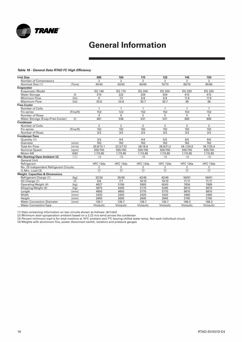
Table 18 - General Data RTAD FC High Efficiency
Unit Size 085 100 115 125 145 150
Number of Compressors 2 2 2 2 2 2Nominal Size (1) (Tons) 40/40 50/50 60/60 70/70 85/70 85/85
Evaporator
Evaporator Model EG 140 EG 170 EG 200 EG 200 EG 250 EG 250Water Storage (l) 270 222 204 204 415 415Minimum Flow (l/s) 6 7.3 8.8 8.8 11.6 11.6Maximum Flow (l/s) 20.8 24.8 30.7 30.7 38 38
Free-Cooler
Number of Coils 1 1 1 1 1 1Fin series (Fins/ft) 152 122 152 152 152 152Number of Rows 4 6 5 5 5 5Water Storage (Evap+Free-Cooler) (l) 481 538 531 531 806 806
Condenser
Number of Coils 2 2 2 2 2 2Fin series (Fins/ft) 192 192 192 192 192 192Number of Rows 3/3 3/3 3/3 3/3 3/3 3/3
Condenser Fans
Quantity (1) 3/3 4/4 4/4 5/5 6/5 6/6Diameter (mm) 762 762 762 762 762 762Total Air Flow (m3/s) 20.8/15.1 23.5/17.2 26/18.9 28.9/21.2 34.1/24.8 34.7/25.4Nominal Speed (rpm) 935/740 935/740 935/740 935/740 935/740 935/740Motor kW (kW) 1.7/0.85 1.7/0.85 1.7/0.85 1.7/0.85 1.7/0.85 1.7/0.85
Min Starting/Oper Ambient (2) (°C) -18 -18 -18 -18 -18 -18General UnitRefrigerant HFC 134a HFC 134a HFC 134a HFC 134a HFC 134a HFC 134a No. Of independent Refrigerant Circuits 2 2 2 2 2 2% Min. Load (3) 17 17 17 17 17 17
Weight. Capacities & Dimensions
Refrigerant Charge (1) (kg) 32/34 35/36 42/45 42/45 59/61 59/61Oil Charge (1) (l) 6/6 7/7 10/10 10/10 11/11 11/11Operating Weight (4) (kg) 4627 5106 5905 6000 7834 7889Shipping Weight (4) (kg) 3875 4345 5170 5265 6615 6670Length (mm) 4850 4850 5770 5770 6810 6810Width (mm) 2420 2420 2420 2420 2460 2460Height (mm) 2605 2605 2645 2645 2745 2745Water Connection Diameter (mm) 139.7 139.7 139.7 139.7 168.3 168.3Water Connection Type Victaulic Victaulic Victaulic Victaulic Victaulic Victaulic
(1) Data containing information on two circuits shown as follows: ckt1/ckt2(2) Minimum start-up/operation ambient based on a 2.22 m/s wind across the condenser(3) Percent minimum load is for total machine at 10°C ambient and 7°C leaving chilled water temp. Not each individual circuit.(4) Weights with aluminium fins, power disconnect switch, isolators and pressure gauges
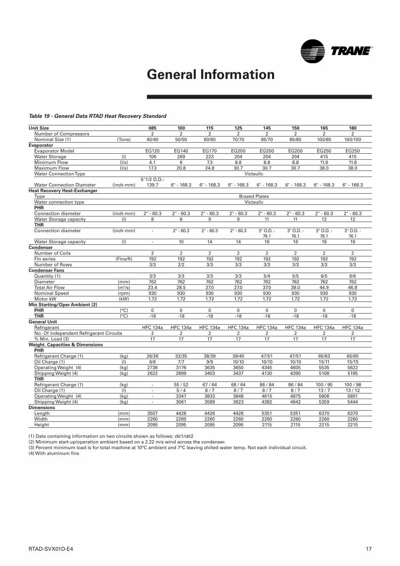
Table 19 - General Data RTAD Heat Recovery Standard
Unit Size 085 100 115 125 145 150 165 180
Number of Compressors 2 2 2 2 2 2 2 2Nominal Size (1) (Tons) 40/40 50/50 60/60 70/70 85/70 85/85 100/85 100/100
Evaporator
Evaporator Model EG120 EG140 EG170 EG200 EG200 EG200 EG250 EG250Water Storage (l) 106 269 223 204 204 204 415 415Minimum Flow (l/s) 4.1 6 7.3 8.8 8.8 8.8 11.6 11.6Maximum Flow (l/s) 17.3 20.8 24.8 30.7 30.7 30.7 38.0 38.0Water Connection Type Victaulic
5"1/2 O.D.-Water Connection Diameter (inch-mm) 139.7 6" - 168.3 6" - 168.3 6" - 168.3 6" - 168.3 6" - 168.3 6" - 168.3 6" - 168.3
Heat Recovery Heat-Exchanger
Type Brazed PlatesWater connection type VictaulicPHR
Connection diameter (inch-mm) 2" - 60.3 2" - 60.3 2" - 60.3 2" - 60.3 2" - 60.3 2" - 60.3 2" - 60.3 2" - 60.3Water Storage capacity (l) 8 8 9 9 11 11 12 12THR
Connection diameter (inch-mm) - 2" - 60.3 2" - 60.3 2" - 60.3 3" O.D. - 3" O.D. - 3" O.D. - 3" O.D. - 76.1 76.1 76.1 76.1
Water Storage capacity (l) - 10 14 14 16 16 19 19Condenser
Number of Coils 2 2 2 2 2 2 2 2Fin series (Fins/ft) 192 192 192 192 192 192 192 192Number of Rows 3/3 2/2 3/3 3/3 3/3 3/3 3/3 3/3
Condenser Fans
Quantity (1) 3/3 3/3 3/3 3/3 5/4 5/5 6/5 6/6Diameter (mm) 762 762 762 762 762 762 762 762Total Air Flow (m3/s) 23.4 28.5 27.0 27.0 37.0 39.0 44.9 46.8Nominal Speed (rpm) 930 930 930 930 930 930 930 930Motor kW (kW) 1.72 1.72 1.72 1.72 1.72 1.72 1.72 1.72
Min Starting/Oper Ambient (2)
PHR (°C) 0 0 0 0 0 0 0 0THR (°C) -18 -18 -18 -18 -18 -18 -18 -18
General Unit
Refrigerant HFC 134a HFC 134a HFC 134a HFC 134a HFC 134a HFC 134a HFC 134a HFC 134a No. Of independent Refrigerant Circuits 2 2 2 2 2 2 2 2% Min. Load (3) 17 17 17 17 17 17 17 17
Weight. Capacities & Dimensions
PHR
Refrigerant Charge (1) (kg) 26/26 33/35 38/39 39/40 47/51 47/51 65/63 65/65Oil Charge (1) (l) 6/6 7/7 9/9 10/10 10/10 10/10 15/11 15/15Operating Weight (4) (kg) 2736 3176 3635 3650 4345 4605 5535 5622Shipping Weight (4) (kg) 2622 2899 3403 3437 4130 4390 5108 5195THR
Refrigerant Charge (1) (kg) - 55 / 52 67 / 64 68 / 64 86 / 84 86 / 84 100 / 95 100 / 98Oil Charge (1) (l) - 5 / 4 8 / 7 8 / 7 8 / 7 8 / 7 13 / 7 13 / 12Operating Weight (4) (kg) - 3347 3833 3848 4615 4875 5806 5891Shipping Weight (4) (kg) - 3061 3589 3623 4382 4642 5359 5444
Dimensions
Length (mm) 3507 4426 4426 4426 5351 5351 6370 6370Width (mm) 2260 2260 2260 2260 2260 2260 2260 2260Height (mm) 2095 2095 2095 2095 2115 2115 2215 2215
(1) Data containing information on two circuits shown as follows: ckt1/ckt2(2) Minimum start-up/operation ambient based on a 2.22 m/s wind across the condenser.(3) Percent minimum load is for total machine at 10°C ambient and 7°C leaving chilled water temp. Not each individual circuit.(4) With aluminum fins
RTAD-SVX01D-E4 17
General Information
18 RTAD-SVX01D-E4
General Information
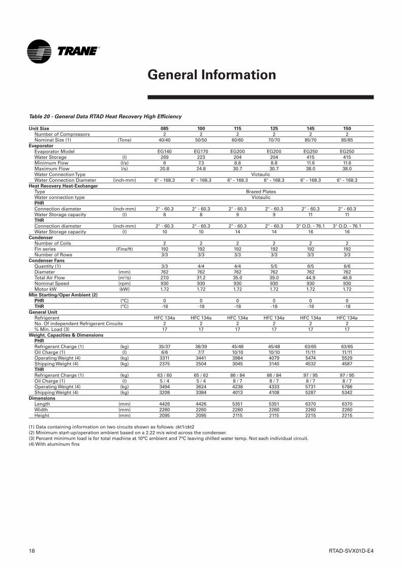
Table 20 - General Data RTAD Heat Recovery High Efficiency
Unit Size 085 100 115 125 145 150
Number of Compressors 2 2 2 2 2 2Nominal Size (1) (Tons) 40/40 50/50 60/60 70/70 85/70 85/85
Evaporator
Evaporator Model EG140 EG170 EG200 EG200 EG250 EG250Water Storage (l) 269 223 204 204 415 415Minimum Flow (l/s) 6 7.3 8.8 8.8 11.6 11.6Maximum Flow l/s) 20.8 24.8 30.7 30.7 38.0 38.0Water Connection Type VictaulicWater Connection Diameter (inch-mm) 6" - 168.3 6" - 168.3 6" - 168.3 6" - 168.3 6" - 168.3 6" - 168.3
Heat Recovery Heat-Exchanger
Type Brazed PlatesWater connection type VictaulicPHR
Connection diameter (inch-mm) 2" - 60.3 2" - 60.3 2" - 60.3 2" - 60.3 2" - 60.3 2" - 60.3Water Storage capacity (l) 8 8 9 9 11 11THR
Connection diameter (inch-mm) 2" - 60.3 2" - 60.3 2" - 60.3 2" - 60.3 3" O.D. - 76.1 3" O.D. - 76.1Water Storage capacity (l) 10 10 14 14 16 16
Condenser
Number of Coils 2 2 2 2 2 2Fin series (Fins/ft) 192 192 192 192 192 192Number of Rows 3/3 3/3 3/3 3/3 3/3 3/3
Condenser Fans
Quantity (1) 3/3 4/4 4/4 5/5 6/5 6/6Diameter (mm) 762 762 762 762 762 762Total Air Flow (m3/s) 27.0 31.2 35.0 39.0 44.9 46.8Nominal Speed (rpm) 930 930 930 930 930 930Motor kW (kW) 1.72 1.72 1.72 1.72 1.72 1.72
Min Starting/Oper Ambient (2)
PHR (°C) 0 0 0 0 0 0THR (°C) -18 -18 -18 -18 -18 -18
General Unit
Refrigerant HFC 134a HFC 134a HFC 134a HFC 134a HFC 134a HFC 134a No. Of independent Refrigerant Circuits 2 2 2 2 2 2% Min. Load (3) 17 17 17 17 17 17
Weight. Capacities & Dimensions
PHR
Refrigerant Charge (1) (kg) 35/37 38/39 45/48 45/48 63/65 63/65Oil Charge (1) (l) 6/6 7/7 10/10 10/10 11/11 11/11Operating Weight (4) (kg) 3311 3441 3984 4079 5474 5529Shipping Weight (4) (kg) 2375 2504 3045 3140 4532 4587THR
Refrigerant Charge (1) (kg) 63 / 60 65 / 62 86 / 84 86 / 84 97 / 95 97 / 95Oil Charge (1) (l) 5 / 4 5 / 4 8 / 7 8 / 7 8 / 7 8 / 7Operating Weight (4) (kg) 3494 3624 4238 4333 5731 5786Shipping Weight (4) (kg) 3208 3384 4013 4108 5287 5342
Dimensions
Length (mm) 4426 4426 5351 5351 6370 6370Width (mm) 2260 2260 2260 2260 2260 2260Height (mm) 2095 2095 2115 2115 2215 2215
(1) Data containing information on two circuits shown as follows: ckt1/ckt2(2) Minimum start-up/operation ambient based on a 2.22 m/s wind across the condenser.(3) Percent minimum load is for total machine at 10°C ambient and 7°C leaving chilled water temp. Not each individual circuit.(4) With aluminum fins
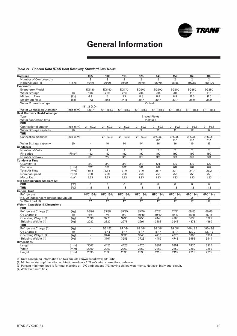
Table 21 - General Data RTAD Heat Recovery Standard Low Noise
Unit Size 085 100 115 125 145 150 165 180
Number of Compressors 2 2 2 2 2 2 2 2Nominal Size (1) (Tons) 40/40 50/50 60/60 70/70 85/70 85/85 100/85 100/100
Evaporator
Evaporator Model EG120 EG140 EG170 EG200 EG200 EG200 EG250 EG250Water Storage (l) 106 269 223 204 204 204 415 415Minimum Flow (l/s) 4.1 6 7.3 8.8 8.8 8.8 11.6 11.6Maximum Flow (l/s) 17.3 20.8 24.8 30.7 30.7 30.7 38.0 38.0Water Connection Type Victaulic
5"1/2 O.D.-Water Connection Diameter (inch-mm) 139.7 6" - 168.3 6" - 168.3 6" - 168.3 6" - 168.3 6" - 168.3 6" - 168.3 6" - 168.3
Heat Recovery Heat-Exchanger
Type Brazed PlatesWater connection type VictaulicPHR
Connection diameter (inch-mm) 2" - 60.3 2" - 60.3 2" - 60.3 2" - 60.3 2" - 60.3 2" - 60.3 2" - 60.3 2" - 60.3Water Storage capacity (l) 8 8 9 9 11 11 12 12THR
Connection diameter (inch-mm) - 2" - 60.3 2" - 60.3 2" - 60.3 3" O.D. - 3" O.D. - 3" O.D. - 3" O.D. - 76.1 76.1 76.1 76.1
Water Storage capacity (l) - 10 14 14 16 16 19 19Condenser
Number of Coils 2 2 2 2 2 2 2 2Fin series (Fins/ft) 192 192 192 192 192 192 192 192Number of Rows 3/3 2/2 3/3 3/3 3/3 3/3 3/3 3/3
Condenser Fans
Quantity (1) 3/3 3/3 3/3 3/3 5/4 5/5 6/5 6/6Diameter (mm) 762 762 762 762 762 762 762 762Total Air Flow (m3/s) 18.1 22.4 21.0 21.0 28.7 30.1 34.7 36.2Nominal Speed (rpm) 750 750 750 750 750 750 750 750Motor kW (kW) 1.23 1.23 1.23 1.23 1.23 1.23 1.23 1.23
Min Starting/Oper Ambient (2)
PHR (°C) 0 0 0 0 0 0 0 0THR (°C) -18 -18 -18 -18 -18 -18 -18 -18
General Unit
Refrigerant HFC 134a HFC 134a HFC 134a HFC 134a HFC 134a HFC 134a HFC 134a HFC 134a No. Of independent Refrigerant Circuits 2 2 2 2 2 2 2 2% Min. Load (3) 17 17 17 17 17 17 17 17
Weight. Capacities & Dimensions
PHR
Refrigerant Charge (1) (kg) 26/26 33/35 38/39 39/40 47/51 47/51 65/63 65/65Oil Charge (1) (l) 6/6 7/7 9/9 10/10 10/10 10/10 15/11 15/15Operating Weight (4) (kg) 2836 3276 3735 3750 4445 4705 5635 5722Shipping Weight (4) (kg) 2082 2520 2978 2991 3686 3946 4873 4960THR
Refrigerant Charge (1) (kg) - 55 / 52 67 / 64 68 / 64 86 / 84 86 / 84 100 / 95 100 / 98Oil Charge (1) (l) - 5 / 4 8 / 7 8 / 7 8 / 7 8 / 7 13 / 7 13 / 12Operating Weight (4) (kg) - 3447 3933 3948 4715 4975 5906 5991Shipping Weight (4) (kg) - 3161 3689 3723 4482 4742 5459 5544
Dimensions
Length (mm) 3507 4426 4426 4426 5351 5351 6370 6370Width (mm) 2260 2260 2260 2260 2260 2260 2260 2260Height (mm) 2095 2095 2095 2095 2115 2115 2215 2215
(1) Data containing information on two circuits shown as follows: ckt1/ckt2(2) Minimum start-up/operation ambient based on a 2.22 m/s wind across the condenser.(3) Percent minimum load is for total machine at 10°C ambient and 7°C leaving chilled water temp. Not each individual circuit.(4) With aluminum fins
RTAD-SVX01D-E4 19
General Information
20 RTAD-SVX01D-E4
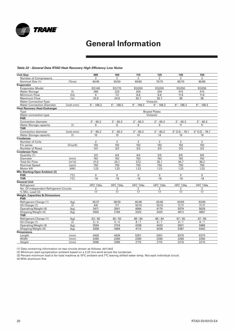
Table 22 - General Data RTAD Heat Recovery High Efficiency Low Noise
Unit Size 085 100 115 125 145 150
Number of Compressors 2 2 2 2 2 2Nominal Size (1) (Tons) 40/40 50/50 60/60 70/70 85/70 85/85
Evaporator
Evaporator Model EG140 EG170 EG200 EG200 EG250 EG250Water Storage (l) 269 223 204 204 415 415Minimum Flow (l/s) 6 7.3 8.8 8.8 11.6 11.6Maximum Flow l/s) 20.8 24.8 30.7 30.7 38 38Water Connection Type VictaulicWater Connection Diameter (inch-mm) 6" - 168.3 6" - 168.3 6" - 168.3 6" - 168.3 6" - 168.3 6" - 168.3
Heat Recovery Heat-Exchanger
Type Brazed PlatesWater connection type VictaulicPHR
Connection diameter 2" - 60.3 2" - 60.3 2" - 60.3 2" - 60.3 2" - 60.3 2" - 60.3Water Storage capacity (l) 8 8 9 9 11 11THR
Connection diameter (inch-mm) 2" - 60.3 2" - 60.3 2" - 60.3 2" - 60.3 3" O.D. - 76.1 3" O.D. - 76.1Water Storage capacity (l) 10 10 14 14 16 16
Condenser
Number of Coils 2 2 2 2 2 2Fin series (Fins/ft) 192 192 192 192 192 192Number of Rows 3/3 3/3 3/3 3/3 3/3 3/3
Condenser Fans
Quantity (1) 3/3 4/4 4/4 5/5 6/5 6/6Diameter (mm) 762 762 762 762 762 762Total Air Flow (m3/s) 21.0 24.1 27.2 30.1 34.7 36.2Nominal Speed (rpm) 750 750 750 750 750 750Motor kW (kW) 1.23 1.23 1.23 1.23 1.23 1.23
Min Starting/Oper Ambient (2)
PHR (°C) 0 0 0 0 0 0THR (°C) -18 -18 -18 -18 -18 -18
General Unit
Refrigerant HFC 134a HFC 134a HFC 134a HFC 134a HFC 134a HFC 134a No. Of independent Refrigerant Circuits 2 2 2 2 2 2% Min. Load (3) 17 17 17 17 17 17
Weight. Capacities & Dimensions
PHR
Refrigerant Charge (1) (kg) 35/37 38/39 45/48 45/48 63/65 63/65Oil Charge (1) (l) 6/6 7/7 10/10 10/10 11/11 11/11Operating Weight (4) (kg) 3411 3541 4084 4179 5574 5629Shipping Weight (4) (kg) 2655 2784 3325 3420 4812 4867THR
Refrigerant Charge (1) (kg) 63 / 60 65 / 62 86 / 84 86 / 84 97 / 95 97 / 95Oil Charge (1) (l) 5 / 4 5 / 4 8 / 7 8 / 7 8 / 7 8 / 7Operating Weight (4) (kg) 3594 3724 4338 4433 5831 5886Shipping Weight (4) (kg) 3308 3484 4113 4208 5387 5442
Dimensions
Length (mm) 4426 4426 5351 5351 6370 6370Width (mm) 2260 2260 2260 2260 2260 2260Height (mm) 2095 2095 2115 2115 2215 2215
(1) Data containing information on two circuits shown as follows: ckt1/ckt2(2) Minimum start-up/operation ambient based on a 2.22 m/s wind across the condenser.(3) Percent minimum load is for total machine at 10°C ambient and 7°C leaving chilled water temp. Not each individual circuit.(4) With aluminum fins
General Information
RTAD-SVX01D-E4 21
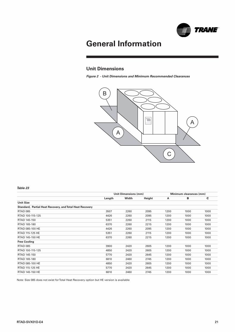
Unit Dimensions
Figure 2 - Unit Dimensions and Minimum Recommended Clearances
RTAD-SVX01D-E4 21
General Information
Table 23
Note: Size 085 does not exist for Total Heat Recovery option but HE version is available
Unit Dimensions (mm) Minimum clearances (mm)
Length Width Height A B C
Unit Size
Standard, Partial Heat Recovery, and Total Heat Recovery
RTAD 085 3507 2260 2095 1200 1000 1000
RTAD 100-115-125 4426 2260 2095 1200 1000 1000
RTAD 145-150 5351 2260 2115 1200 1000 1000
RTAD 165-180 6370 2260 2215 1200 1000 1000
RTAD 085-100 HE 4426 2260 2095 1200 1000 1000
RTAD 115-125 HE 5351 2260 2115 1200 1000 1000
RTAD 145-150 HE 6370 2260 2215 1200 1000 1000
Free Cooling
RTAD 085 3900 2420 2605 1200 1000 1000
RTAD 100-115-125 4850 2420 2605 1200 1000 1000
RTAD 145-150 5770 2420 2645 1200 1000 1000
RTAD 165-180 6810 2460 2745 1200 1000 1000
RTAD 085-100 HE 4850 2420 2605 1200 1000 1000
RTAD 115-125 HE 5770 2420 2645 1200 1000 1000
RTAD 145-150 HE 6810 2460 2745 1200 1000 1000
22 RTAD-SVX01D-E4
Installation - Mechanical
Installation Responsibilities Generally, the contractor must do thefollowing when installing an RTADunit:❏ Install unit on a flat foundation,
level (within 1/4" [6 mm] acrossthe length of the unit), and strongenough to support unit loading.
❏ Install unit per the instructionscontained in this manual.
❏ Install any optional sensors andmake electrical connections at theUCM-CLD.
❏ Where specified, provide andinstall valves in water pipingupstream and downstream ofevaporator water connections toisolate the evaporator formaintenance, and to balance/trimsystem.
❏ Furnish and install flow switchand/or auxiliary contacts to provechilled water flow.
❏ Furnish and install pressuregauges in inlet and outlet piping ofthe evaporator.
❏ Furnish and install a drain valve tothe bottom of the evaporator shell.
❏ Supply and install a vent cock tothe top of the evaporator shell.
❏ Furnish and install strainers aheadof all pumps and automaticmodulating valves.
❏ Provide and install field wiring.❏ Install heat tape and insulate the
chilled water lines and any otherportions of the system, asrequired, to prevent sweatingunder normal operating conditionsor freezing during low ambienttemperature conditions.
❏ Start unit under supervision of aqualified service technician.
NameplatesThe RTAD outdoor unit nameplates(Figure 1) are applied to the exteriorof the control panel. A compressornameplate is located on eachcompressor.Outdoor Unit Nameplate
The outdoor unit nameplate providesthe following information:• Unit model and size description• Unit serial number• Identifies unit electrical
requirements• Lists correct operating charges of
R-134a and refrigerant oil (TraneOIL00048)
• Lists unit test pressuresCompressor Nameplate
The compressor nameplate providesfollowing information:• Compressor model number.• Compressor serial number.• Compressor electrical
characteristics.• Utilization range• Recommended refrigerant
RTAD-SVX01D-E4 23
Installation - Mechanical
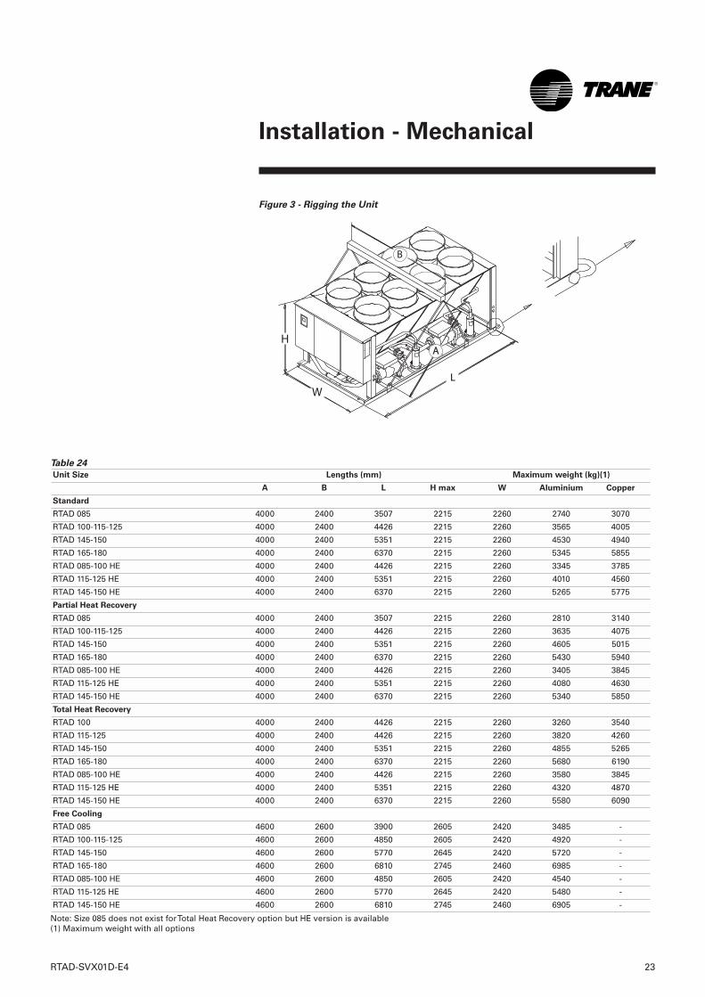
Figure 3 - Rigging the Unit
A
L
H
W
B
Table 24
Note: Size 085 does not exist for Total Heat Recovery option but HE version is available(1) Maximum weight with all options
Unit Size Lengths (mm) Maximum weight (kg)(1)
A B L H max W Aluminium Copper
Standard
RTAD 085 4000 2400 3507 2215 2260 2740 3070
RTAD 100-115-125 4000 2400 4426 2215 2260 3565 4005
RTAD 145-150 4000 2400 5351 2215 2260 4530 4940
RTAD 165-180 4000 2400 6370 2215 2260 5345 5855
RTAD 085-100 HE 4000 2400 4426 2215 2260 3345 3785
RTAD 115-125 HE 4000 2400 5351 2215 2260 4010 4560
RTAD 145-150 HE 4000 2400 6370 2215 2260 5265 5775
Partial Heat Recovery
RTAD 085 4000 2400 3507 2215 2260 2810 3140
RTAD 100-115-125 4000 2400 4426 2215 2260 3635 4075
RTAD 145-150 4000 2400 5351 2215 2260 4605 5015
RTAD 165-180 4000 2400 6370 2215 2260 5430 5940
RTAD 085-100 HE 4000 2400 4426 2215 2260 3405 3845
RTAD 115-125 HE 4000 2400 5351 2215 2260 4080 4630
RTAD 145-150 HE 4000 2400 6370 2215 2260 5340 5850
Total Heat Recovery
RTAD 100 4000 2400 4426 2215 2260 3260 3540
RTAD 115-125 4000 2400 4426 2215 2260 3820 4260
RTAD 145-150 4000 2400 5351 2215 2260 4855 5265
RTAD 165-180 4000 2400 6370 2215 2260 5680 6190
RTAD 085-100 HE 4000 2400 4426 2215 2260 3580 3845
RTAD 115-125 HE 4000 2400 5351 2215 2260 4320 4870
RTAD 145-150 HE 4000 2400 6370 2215 2260 5580 6090
Free Cooling
RTAD 085 4600 2600 3900 2605 2420 3485 -
RTAD 100-115-125 4600 2600 4850 2605 2420 4920 -
RTAD 145-150 4600 2600 5770 2645 2420 5720 -
RTAD 165-180 4600 2600 6810 2745 2460 6985 -
RTAD 085-100 HE 4600 2600 4850 2605 2420 4540 -
RTAD 115-125 HE 4600 2600 5770 2645 2420 5480 -
RTAD 145-150 HE 4600 2600 6810 2745 2460 6905 -
24 RTAD-SVX01D-E4
Installation - Mechanical
Location Requirements Isolation and Sound Emission
The most effective form of isolationis to locate the unit away from anysound sensitive area. Structurallytransmitted sound can be reduced byelastomeric vibration eliminators.Spring isolators are notrecommended. Consult an acousticalengineer in critical soundapplications. For maximum isolationeffect, isolate water lines andelectrical conduit. Wall sleeves andrubber isolated piping hangers canbe used to reduce the soundtransmitted through water piping. Toreduce the sound transmittedthrough electrical conduit, useflexible electrical conduit. State andlocal codes on sound emissionsshould always be considered. Sincethe environment in which a soundsource is located affects soundpressure, unit placement must becarefully evaluated. Sound powerlevels for Trane air-cooled RTADchillers are available on request.For additional reduction of soundand vibration, install the optionalneoprene isolators. Construct anisolated concrete pad for the unit orprovide concrete footings at the unitmounting points. Mount the unitdirectly to the concrete pads orfootings. Level the unit using thebase rail as a reference. Use shimsas necessary to level the unit.
Neoprene Isolator (optional)
Installation
Refer to submittals for diagrams.1 Secure the isolators to the
mounting surface using themounting slots in the isolator baseplate. DO NOT fully tighten theisolator mounting bolts at thistime.
2 Align the mounting holes in thebase of the unit with the threadedpositioning pins on the top of theisolators.
3 Lower the unit onto the isolatorsand secure the isolator to the unitwith a nut. Maximum isolatordeflection should be 1/4 inch(6 mm).
4 Level the unit carefully. Fullytighten the isolator mounting bolts.
Noise Considerations
Locate the outdoor unit away fromsound sensitive areas. If required,install rubber vibration isolators inall water piping and use flexibleelectrical conduit. Consult anacoustical engineer for criticalapplications. Also refer to TraneEngineering Bulletins for applicationinformation on RTAD chillers.
Important note for Free-cooling
units:
To reduce sound levels, a soundenclosure can be mounted aroundthe compressors. For further soundlevel reduction, the fan speedshould be forced onto low speed(e.g. 740 rpm). This can be doneusing the control panel. Make surethat option 20, shown on the wiringdiagram, is correctly wired.
StorageExtended storage of the outdoor unitprior to installation requires thefollowing precautionary measures:• Store the outdoor unit in a secure
area.• At least every three months
(quarterly), check the pressure inthe refrigerant circuits to verify thatthe refrigerant charge is intact. If itis not, contact a qualified serviceorganization and the appropriateTrane sales office.
• Close the discharge and liquid lineisolation valves.
CAUTION! Refer to nameplate for
unit weight and additional
installation instructions contained
inside the control panel. Other lifting
arrangements may cause equipment
damage or serious personal injury.
RTAD-SVX01D-E4 25
Installation - Mechanical
Foundation
Provide rigid, non-warping mountingpads or a concrete foundation ofsufficient strength and mass tosupport the outdoor unit operatingweight (i.e., including completedpiping, and full operating charges ofrefrigerant, oil and water). Refer toTables 1-18 for unit operatingweights. Once in place, the outdoorunit must be level within 1/4" (6 mm)over its length and width. A base orfoundation is not required if theselected unit location is level andstrong enough to support the unit'soperating weight. Trane is notresponsible for equipment problemsresulting from an improperlydesigned or constructed foundation.Note: To allow for cleaning under thecondensing coil, it is recommendedthat an opening be left between theunit base and the concrete pad.
Clearances
Refer to Figure 2 for minimumclearances. Provide enough spacearound the outdoor unit to allow theinstallation and maintenancepersonnel unrestricted access to allservice points. Refer to submittaldrawings for the unit dimensions. Aminimum of four feet isrecommended for compressorservice. Provide sufficient clearancefor the opening of control paneldoors. In all cases, local codes whichrequire additional clearances willtake precedence over theserecommendations.
Unobstructed flow of condenser airis essential to maintain chillercapacity and operating efficiency.When determining unit placement,give careful consideration toassuring a sufficient flow of airacross the condenser heat transfersurface. Two detrimental conditionsare possible and must be avoided ifoptimum performance is to beachieved: warm air recirculation andcoil starvation. Warm air recirculationoccurs when discharge air from thecondenser fans is recycled back tothe condenser coil inlet. Coilstarvation occurs when free airflowto (or from) the condenser isrestricted. Both warm airrecirculation and coil starvationcause reduction in unit efficiency andcapacity due to the increased headpressures. Debris, trash, supplies etc.should not be allowed to accumulatein the vicinity of the unit. Supply airmovement may draw debris into thecondenser coil, blocking spacesbetween coil fins and causing coilstarvation. Special considerationshould be given to low ambientunits. Condenser coils and fandischarge must be kept free of snowor other obstructions to permitadequate airflow for satisfactory unitoperation.
Unit Water PipingThoroughly flush all water piping tothe unit before making the finalpiping connections to the unit.CAUTION! If using an acidic
commercial flushing solution,
construct a temporary bypass
around the unit to prevent damage
to internal components of the
evaporator.To avoid possible
equipment damage, do not use
untreated or improperly treated
system water.
CAUTION! As the unit contains
pressure approved vessels and
sensitive electronic equipment, do
not use arc welding directly on the
unit or even close to the unit. Do not
weld near the Victaulic connections.
Unit PipingComponents and layout will varyslightly, depending on the location ofconnections and the water source.Note: The chilled water piping to theevaporator is to be Victaulic typeconnections. For Free Cooling units,Free Cooling coil connections arealso to be VictaulicTM typeconnections. To prevent damage to chilled watercomponents, do not allowevaporator pressure (maximumworking pressure) to exceed 16 bar.Provide shutoff valves in lines to thegauges to isolate them from thesystem when they are not in use.Use rubber vibration eliminators toprevent vibration transmissionthrough the water lines. If desired,install thermometers in the lines tomonitor entering and leaving watertemperatures. Install a balancingvalve in the leaving water line tocontrol water flow balance. Installshutoff valves on both the enteringand leaving water lines so that theevaporator can be isolated forservice.CAUTION! A pipe strainer must be
installed in the entering water line.
Failure to do so can allow
waterborne debris to enter the
evaporator.
"Piping components" include alldevices and controls used to provideproper water system operation andunit operating safety. Thesecomponents and their generallocations are given below.
In situations where equipment mustbe installed with less clearance thanrecommended, such as frequentlyoccurs in retrofit and rooftopapplications, restricted airflow iscommon. The Main Processor willdirect the unit to make as muchchilled water as possible given theactual installed conditions. Consultyour Trane sales engineer for moredetails.Note: If the outdoor unitconfiguration requires a variance tothe clearance dimensions, contactyour Trane Sales OfficeRepresentative. Also refer to TraneEngineering Bulletins for applicationinformation on RTAD chillers.
Drainage
Provide a large capacity drain forwater vessel drain-down duringshutdown or repair. The evaporatoris provided with a drain connection.All local and national codes apply.The vent on the top of theevaporator shell is provided toprevent a vacuum by allowing airinto the evaporator for completedrainage.
26 RTAD-SVX01D-E4
Installation - Mechanical
RTAD-SVX01D-E4 27
Installation - Mechanical
Leaving Chilled Water
Piping❏ Air vents (to bleed air from
system).❏ Water pressure gauges with
shutoff valves. ❏ Vibration eliminators.❏ Shutoff (isolation) valves.❏ Thermometers.❏ Clean-out tees.❏ Balancing valve.❏ Flow SwitchCAUTION! To prevent evaporator
damage, do not exceed 16 bar
evaporator water pressure.
Heat Recovery Water PipingEntering:
❏ Air vents❏ Water pressure gauges❏ Vibration eliminator / expansion
compensator❏ Shutoff valve❏ Thermometers❏ Pipe strainer❏ Clean-out tees
Leaving:
❏ Air vents❏ Water pressure gauges❏ Vibration eliminator / expansion
compensator❏ Shutoff valve❏ Thermometers❏ Balancing valve❏ Clean-out tees
Evaporator DrainA 3/4" drain connection is locatedunder the evaporator shell. This maybe connected to a suitable drain topermit evaporator drainage duringunit servicing. A shutoff valve mustbe installed on the drain line.
Evaporator Flow SwitchSpecific connection and schematicwiring diagrams are shipped withthe unit. Some piping and controlschemes, particularly those using asingle water pump for both chilledand hot water must be analyzed todetermine how and or if a flow-sensing device will provide desiredoperation.Follow the manufacturer'srecommendations for selection andinstallation procedures. Generalguidelines for flow switch installationare outlined below1. Mount the switch upright, with a
minimum of 5 pipe diameters ofstraight horizontal run on eachside. Do not install close toelbows, orifices or valves.
Note: The arrow on the switch mustpoint in the direction of flow.2. To prevent switch fluttering,
remove all air from the watersystem.
Note: The UCM-CLD provides a 6-second time delay after a "loss-of-flow" diagnostic before shutting theunit down. Contact a qualifiedservice representative if nuisancemachine shutdowns persist.3. Adjust the switch to open when
water flow falls below nominal.Evaporator data is given inTables 1-22. Flow switch contacts areclosed on proof of water flow.4. Install a pipe strainer in the
entering evaporator water line toprotect components fromwaterborne debris.
Entering Chilled Water
Piping❏ Air vents (to bleed air from
system).❏ Water pressure gauges with
shutoff valves.❏ Vibration eliminators.❏ Shutoff (isolation) valves.
Thermometers (if desired).❏ Clean-out tees.❏ Pipe strainer.CAUTION! Install strainer in
evaporator water inlet piping. Failure
to do so can result in evaporator
tube damage.
Water TreatmentCAUTION! If calcium chloride is used
for water treatment, an applicable
corrosion inhibitor must also be
used. Failure to do so may result in
damage to system components.
Dirt, scale, products of corrosion andother foreign material will adverselyaffect heat transfer between thewater and system components.Foreign matter in the chilled watersystem can also increase pressuredrop and, consequently, reducewater flow.
Proper water treatment must bedetermined locally, depending on thetype of system and local watercharacteristics. Neither salt norbrackish water is recommended foruse in Trane air-cooled Series R™chillers. Use of either will lead to ashortened life to an indeterminabledegree. Trane encourages theemployment of a reputable watertreatment specialist, familiar withlocal water conditions, to assist inthis determination and in theestablishment of a proper watertreatment program.Using untreated or improperlytreated water in these units mayresult in inefficient operation andpossible tube damage. Consult aqualified water treatment specialistto determine whether treatment isneeded. The following disclamatorylabel is provided on each RTAD unit:Note: The use of improperly treatedor untreated water in this equipmentmay result in scaling, erosion,corrosion, algae or slime. Theservices of a qualified watertreatment specialist should beengaged to determine whattreatment, if any, is advisable. Tranewarranty specifically excludesliability for corrosion, erosion ordeterioration of Trane equipment.CAUTION! Do not use untreated or
improperly treated water. Equipment
damage may occur.
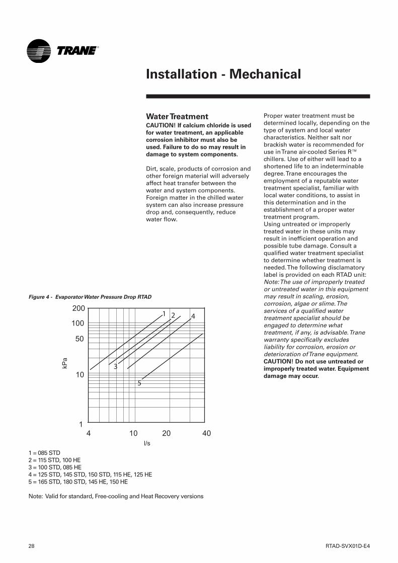
Figure 4 - Evaporator Water Pressure Drop RTAD
1 = 085 STD2 = 115 STD, 100 HE3 = 100 STD, 085 HE4 = 125 STD, 145 STD, 150 STD, 115 HE, 125 HE5 = 165 STD, 180 STD, 145 HE, 150 HE
Note: Valid for standard, Free-cooling and Heat Recovery versions
28 RTAD-SVX01D-E4
Installation - Mechanical
Installation - Mechanical
RTAD-SVX01D-E4 29
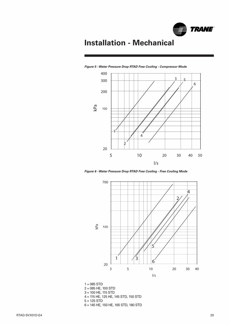
Figure 5 - Water Pressure Drop RTAD Free Cooling - Compressor Mode
Figure 6 - Water Pressure Drop RTAD Free Cooling - Free Cooling Mode
1 = 085 STD2 = 085 HE, 100 STD 3 = 100 HE, 115 STD4 = 115 HE, 125 HE, 145 STD, 150 STD 5 = 125 STD6 = 145 HE, 150 HE, 165 STD, 180 STD
30 RTAD-SVX01D-E4
Installation - Mechanical
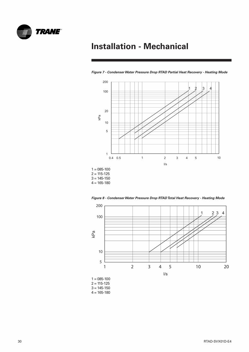
Figure 7 - Condenser Water Pressure Drop RTAD Partial Heat Recovery - Heating Mode
1 = 085-1002 = 115-1253 = 145-1504 = 165-180
Figure 8 - Condenser Water Pressure Drop RTAD Total Heat Recovery - Heating Mode
1 = 085-1002 = 115-1253 = 145-1504 = 165-180
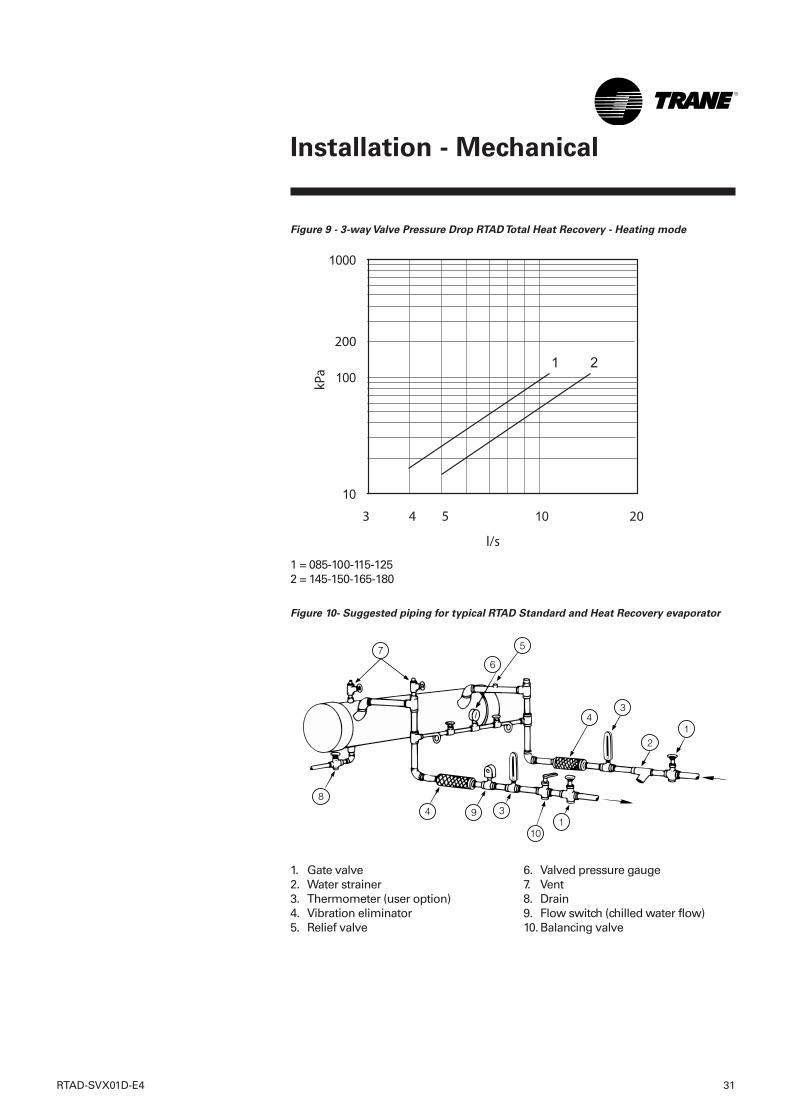
Figure 9 - 3-way Valve Pressure Drop RTAD Total Heat Recovery - Heating mode
1 = 085-100-115-1252 = 145-150-165-180
Figure 10- Suggested piping for typical RTAD Standard and Heat Recovery evaporator
7
8
9
10
6
5
43
21
134
RTAD-SVX01D-E4 31
Installation - Mechanical
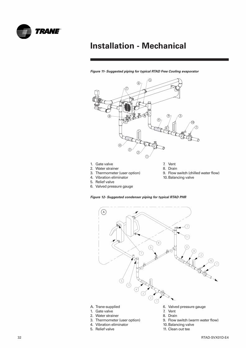
1. Gate valve2. Water strainer3. Thermometer (user option)4. Vibration eliminator5. Relief valve
6. Valved pressure gauge7. Vent8. Drain9. Flow switch (chilled water flow)10.Balancing valve
A. Trane-supplied1. Gate valve2. Water strainer3. Thermometer (user option)4. Vibration eliminator5. Relief valve
6. Valved pressure gauge7. Vent8. Drain9. Flow switch (warm water flow)10.Balancing valve11. Clean out tee
Figure 11- Suggested piping for typical RTAD Free Cooling evaporator
Figure 12- Suggested condenser piping for typical RTAD PHR
1. Gate valve2. Water strainer3. Thermometer (user option)4. Vibration eliminator5. Relief valve6. Valved pressure gauge
7. Vent8. Drain9. Flow switch (chilled water flow)10.Balancing valve
32 RTAD-SVX01D-E4
Installation - Mechanical
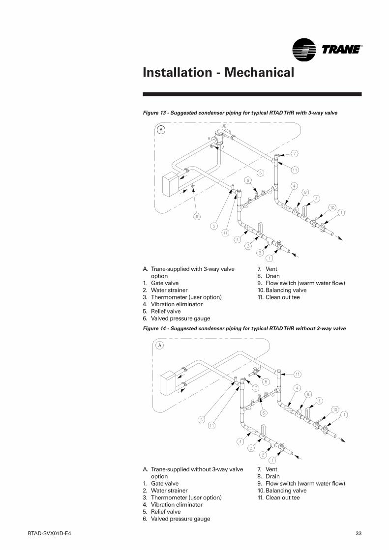
A. Trane-supplied with 3-way valveoption
1. Gate valve2. Water strainer3. Thermometer (user option)4. Vibration eliminator5. Relief valve6. Valved pressure gauge
7. Vent8. Drain9. Flow switch (warm water flow)10.Balancing valve11. Clean out tee
Figure 14 - Suggested condenser piping for typical RTAD THR without 3-way valve
A. Trane-supplied without 3-way valveoption
1. Gate valve2. Water strainer3. Thermometer (user option)4. Vibration eliminator5. Relief valve6. Valved pressure gauge
7. Vent8. Drain9. Flow switch (warm water flow)10.Balancing valve11. Clean out tee
Figure 13 - Suggested condenser piping for typical RTAD THR with 3-way valve
RTAD-SVX01D-E4 33
Installation - Mechanical
34 RTAD-SVX01D-E4
Installation - Mechanical
Freeze ProtectionIf the unit will remain operational atsubfreezing ambient temperatures,the chilled water system must beprotected from freezing, followingthe steps listed below1 Heaters are factory-installed on the
packaged unit evaporator and willprotect it from freezing in ambienttemperatures down to -18°C (0°F).
2 Install heat tape on all waterpiping, pumps, and othercomponents that may be damagedif exposed to freezingtemperatures. Heat tape must bedesigned for low ambienttemperature applications. Heattape selection should be based onthe lowest expected ambienttemperature.
3 Add a non-freezing, lowtemperature, corrosion inhibiting,heat transfer fluid to the chilledwater system. The solution must bestrong enough to provideprotection against ice formation atthe lowest anticipated ambienttemperature. Refer to Tables 1-22for evaporator water storagecapacities.
Note: Use of glycol type antifreezereduces the cooling capacity of theunit and must be considered in thedesign of the system specifications.
Note: All Free Cooling units must befreeze protected with 30% EthyleneGlycol in the cooling loop circuitwhich is the most convenientpercentage in order to protect theunit against freezing.
Protection coverage with 30%Ethylene Glycol:- freezing point without burst effect
= - 13°C;- freezing point with burst effect
= - 50°C.
In ambient temperatures below -18°C, the water circuit must beprotected against freezing by the oneof the following methods:- purge the water circuit or add an an
anti-freeze fluid.- Activate the heat tapes on the unit
and do not shut the unit down.
Heat Recovery UnitsThe heat recovery condenser(s) is(are) insulated and a heater isfactory-installed and will protectfrom freezing in ambienttemperatures down to -18°C.Note: The inlet and outlet tubes andthe optional 3-way valve (Total HeatRecovery units) should be protectedagainst freezing by one of thefollowing methods:- install heat tape on all water piping
and around the 3-way valve- add ethylene glycol or equivalent
anti-freeze fluid.
Water Pressure Gauges
Install field-supplied pressurecomponents as shown inFigure 10-14. Locate pressure gaugesor taps in a straight run of pipe;avoid placement near elbows, etc. Besure to install the gauges at thesame elevation on each shell if theshells have opposite-end waterconnections.To read manifolded pressure gauges,open one valve and close the other(depending upon the readingdesired). This eliminates errorsresulting from differently calibratedgauges installed at unmatchedelevations.
Water Pressure Relief
ValvesCAUTION! To prevent shell damage,
install pressure relief valves in the
evaporator water system.
Install a water pressure relief valve inthe evaporator inlet piping betweenthe evaporator and the inlet shutoffvalve, as shown in Figures 10 and 11.Water vessels with close-coupledshutoff valves have a high potentialfor hydrostatic pressure buildup on awater temperature increase. Refer toapplicable codes for relief valveinstallation guidelines.
Installation - Electrical
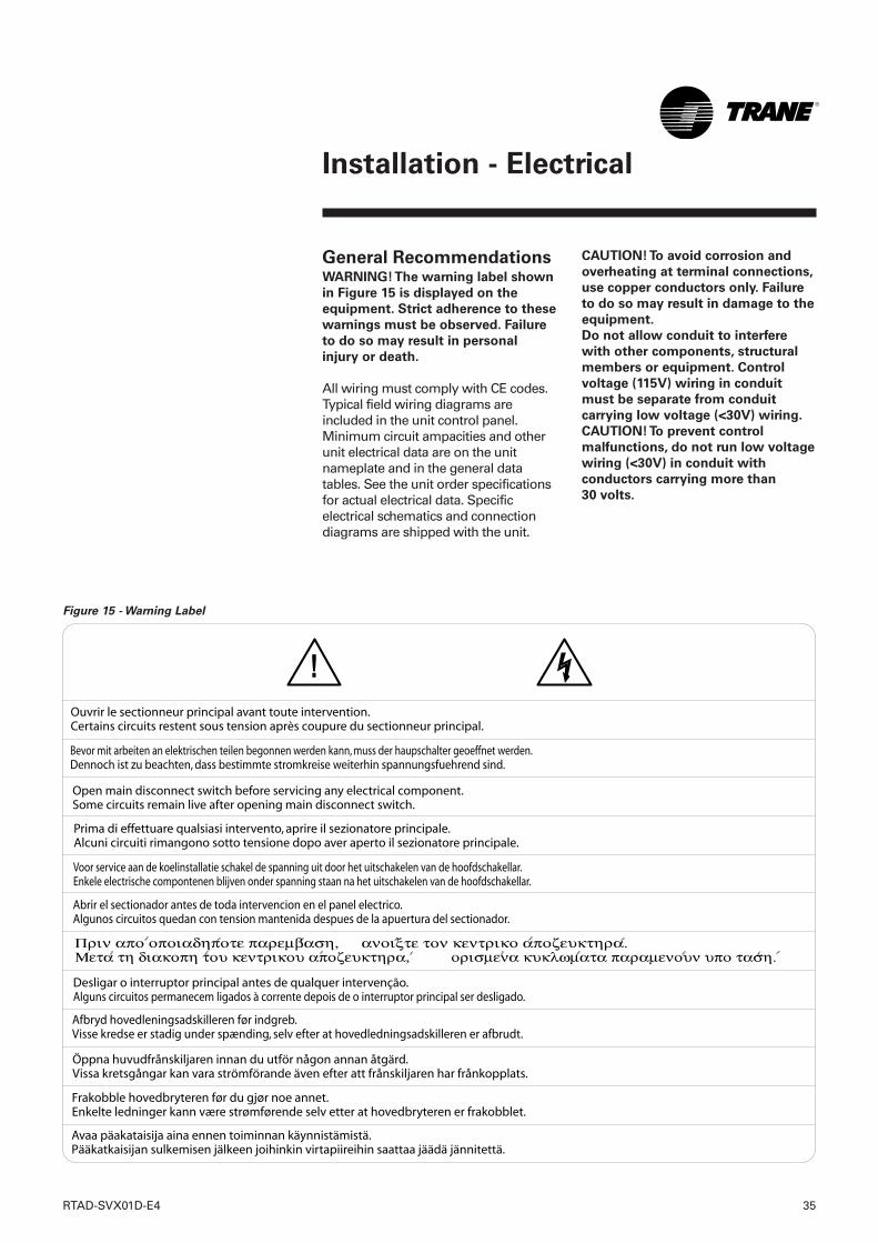
General RecommendationsWARNING! The warning label shown
in Figure 15 is displayed on the
equipment. Strict adherence to these
warnings must be observed. Failure
to do so may result in personal
injury or death.
All wiring must comply with CE codes.Typical field wiring diagrams areincluded in the unit control panel.Minimum circuit ampacities and otherunit electrical data are on the unitnameplate and in the general datatables. See the unit order specificationsfor actual electrical data. Specificelectrical schematics and connectiondiagrams are shipped with the unit.
Figure 15 - Warning Label
CAUTION! To avoid corrosion and
overheating at terminal connections,
use copper conductors only. Failure
to do so may result in damage to the
equipment.
Do not allow conduit to interfere
with other components, structural
members or equipment. Control
voltage (115V) wiring in conduit
must be separate from conduit
carrying low voltage (<30V) wiring.
CAUTION! To prevent control
malfunctions, do not run low voltage
wiring (<30V) in conduit with
conductors carrying more than
30 volts.
RTAD-SVX01D-E4 35
36 RTAD-SVX01D-E4
Installation - Electrical
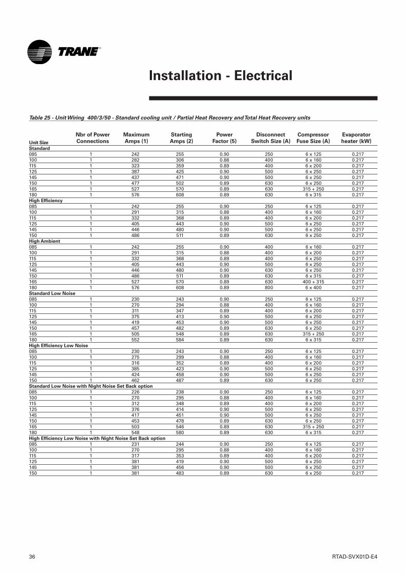
Table 25 - Unit Wiring 400/3/50 - Standard cooling unit / Partial Heat Recovery and Total Heat Recovery units
Unit Size
Standard
085 1 242 255 0.90 250 6 x 125 0.217100 1 282 306 0.88 400 6 x 160 0.217115 1 323 359 0.89 400 6 x 200 0.217125 1 387 425 0.90 500 6 x 250 0.217145 1 437 471 0.90 500 6 x 250 0.217150 1 477 502 0.89 630 6 x 250 0.217165 1 527 570 0.89 630 315 + 250 0.217180 1 576 608 0.89 630 6 x 315 0.217High Efficiency
085 1 242 255 0.90 250 6 x 125 0.217100 1 291 315 0.88 400 6 x 160 0.217115 1 332 368 0.89 400 6 x 200 0.217125 1 405 443 0.90 500 6 x 250 0.217145 1 446 480 0.90 500 6 x 250 0.217150 1 486 511 0.89 630 6 x 250 0.217High Ambient
085 1 242 255 0.90 400 6 x 160 0.217100 1 291 315 0.88 400 6 x 200 0.217115 1 332 368 0.89 400 6 x 250 0.217125 1 405 443 0.90 500 6 x 250 0.217145 1 446 480 0.90 630 6 x 250 0.217150 1 486 511 0.89 630 6 x 315 0.217165 1 527 570 0.89 630 400 + 315 0.217180 1 576 608 0.89 800 6 x 400 0.217Standard Low Noise
085 1 230 243 0.90 250 6 x 125 0.217100 1 270 294 0.88 400 6 x 160 0.217115 1 311 347 0.89 400 6 x 200 0.217125 1 375 413 0.90 500 6 x 250 0.217145 1 419 453 0.90 500 6 x 250 0.217150 1 457 482 0.89 630 6 x 250 0.217165 1 505 548 0.89 630 315 + 250 0.217180 1 552 584 0.89 630 6 x 315 0.217High Efficiency Low Noise
085 1 230 243 0.90 250 6 x 125 0.217100 1 275 299 0.88 400 6 x 160 0.217115 1 316 352 0.89 400 6 x 200 0.217125 1 385 423 0.90 500 6 x 250 0.217145 1 424 458 0.90 500 6 x 250 0.217150 1 462 487 0.89 630 6 x 250 0.217Standard Low Noise with Night Noise Set Back option
085 1 226 238 0.90 250 6 x 125 0.217100 1 270 295 0.88 400 6 x 160 0.217115 1 312 348 0.89 400 6 x 200 0.217125 1 376 414 0.90 500 6 x 250 0.217145 1 417 451 0.90 500 6 x 250 0.217150 1 453 478 0.89 630 6 x 250 0.217165 1 503 546 0.89 630 315 + 250 0.217180 1 548 580 0.89 630 6 x 315 0.217High Efficiency Low Noise with Night Noise Set Back option
085 1 231 244 0.90 250 6 x 125 0.217100 1 270 295 0.88 400 6 x 160 0.217115 1 317 353 0.89 400 6 x 200 0.217125 1 381 419 0.90 500 6 x 250 0.217145 1 381 456 0.90 500 6 x 250 0.217150 1 381 483 0.89 630 6 x 250 0.217
Nbr of Power
Connections
Maximum
Amps (1)
Starting
Amps (2)
Power
Factor (5)
Disconnect
Switch Size (A)
Compressor
Fuse Size (A)
Evaporator
heater (kW)
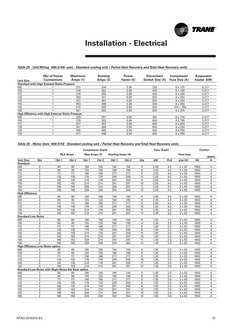
Installation - Electrical
Table 25 - Unit Wiring 400/3/50/ cont - Standard cooling unit / Partial Heat Recovery and Total Heat Recovery units
Unit Size
Standard with High External Static Pressure
085 1 231 244 0.90 250 6 x 125 0.217100 1 278 302 0.88 400 6 x 160 0.217115 1 319 355 0.89 400 6 x 200 0.217125 1 383 421 0.90 500 6 x 250 0.217145 1 427 461 0.90 500 6 x 250 0.217150 1 463 488 0.89 630 6 x 250 0.217165 1 516 559 0.89 630 315 + 250 0.217180 1 561 593 0.89 630 6 x 315 0.217High Efficiency with High External Static Pressure
085 1 239 251 0.90 250 6 x 125 0.217100 1 278 302 0.88 400 6 x 160 0.217115 1 327 363 0.89 400 6 x 200 0.217125 1 391 429 0.90 500 6 x 250 0.217145 1 435 469 0.90 500 6 x 250 0.217150 1 471 496 0.89 630 6 x 250 0.217
Table 26 - Motor Data 400/3/50 - Standard cooling unit / Partial Heat Recovery and Total Heat Recovery units
(400V)
Unit Size Qty Ckt 1 Ckt 2 Ckt 1 Ckt 2 Ckt 1 Ckt 2 Qty kW FLA size (A) VA A
Standard
085 2 80 80 106 106 144 144 6 2.05 4.5 3 x 50 1600 4100 2 95 95 125 125 180 180 6 2.05 4.5 3 x 50 1600 4115 2 111 111 146 146 217 217 6 2.05 4.5 3 x 50 1600 4125 2 135 135 178 178 259 259 6 2.05 4.5 3 x 50 1600 4145 2 162 135 214 178 291 259 9 2.05 4.5 3 x 63 1600 4150 2 162 162 214 214 291 291 10 2.05 4.5 3 x 63 1600 4165 2 196 162 259 214 354 291 11 2.05 4.5 3 x 63 1600 4180 2 196 196 259 259 354 354 12 2.05 4.5 3 x 63 1600 4High Efficiency
085 2 80 80 106 106 144 144 6 2.05 4.5 3 x 50 1600 4100 2 95 95 125 125 180 180 8 2.05 4.5 3 x 50 1600 4115 2 111 111 146 146 217 217 8 2.05 4.5 3 x 50 1600 4125 2 135 135 178 178 259 259 10 2.05 4.5 3 x 50 1600 4145 2 162 135 214 178 291 259 11 2.05 4.5 3 x 63 1600 4150 2 162 162 214 214 291 291 12 2.05 4.5 3 x 63 1600 4Standard Low Noise
085 2 80 80 106 106 144 144 6 1.30 2.5 3 x 50 1600 4100 2 95 95 125 125 180 180 6 1.30 2.5 3 x 50 1600 4115 2 111 111 146 146 217 217 6 1.30 2.5 3 x 50 1600 4125 2 135 135 178 178 259 259 6 1.30 2.5 3 x 50 1600 4145 2 162 135 214 178 291 259 9 1.30 2.5 3 x 63 1600 4150 2 162 162 214 214 291 291 10 1.30 2.5 3 x 63 1600 4165 2 196 162 259 214 354 291 11 1.30 2.5 3 x 63 1600 4180 2 196 196 259 259 354 354 12 1.30 2.5 3 x 63 1600 4High Efficiency Low Noise option
085 2 80 80 106 106 144 144 6 1.30 2.5 3 x 50 1600 4100 2 95 95 125 125 180 180 8 1.30 2.5 3 x 50 1600 4115 2 111 111 146 146 217 217 8 1.30 2.5 3 x 50 1600 4125 2 135 135 178 178 259 259 10 1.30 2.5 3 x 50 1600 4145 2 162 135 214 178 291 259 11 1.30 2.5 3 x 63 1600 4150 2 162 162 214 214 291 291 12 1.30 2.5 3 x 63 1600 4Standard Low Noise with Night Noise Set Back option
085 2 80 80 106 106 144 144 4 1.05 2.6 3 x 50 1600 4100 2 95 95 125 125 180 180 6 1.05 2.6 3 x 50 1600 4115 2 111 111 146 146 217 217 6 1.05 2.6 3 x 50 1600 4125 2 135 135 178 178 259 259 6 1.05 2.6 3 x 50 1600 4145 2 162 135 214 178 291 259 8 1.05 2.6 3 x 63 1600 4150 2 162 162 214 214 291 291 8 1.05 2.6 3 x 63 1600 4165 2 196 162 259 214 354 291 10 1.05 2.6 3 x 63 1600 4180 2 196 196 259 259 354 354 10 1.05 2.6 3 x 63 1600 4
Nbr of Power
Connections
Maximum
Amps (1)
Starting
Amps (2)
Power
Factor (5)
Disconnect
Switch Size (A)
Compressor
Fuse Size (A)
Evaporator
heater (kW)
RLA Amps Max Amps (3) Starting Amps (4) Fans fuse
Compressor (Each) Fans (Each) Control
RTAD-SVX01D-E4 37
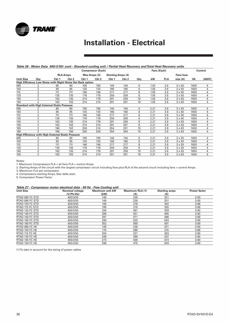
38 RTAD-SVX01D-E4
Installation - Electrical
Table 26 - Motor Data 400/3/50/ cont - Standard cooling unit / Partial Heat Recovery and Total Heat Recovery units
Unit Size Qty Ckt 1 Ckt 2 Ckt 1 Ckt 2 Ckt 1 Ckt 2 Qty kW FLA size (A) VA (400V)
High Efficiency Low Noise with Night Noise Set Back option
085 2 80 80 106 106 144 144 6 1.05 2.6 3 x 50 1600 4100 2 95 95 125 125 180 180 6 1.05 2.6 3 x 50 1600 4115 2 111 111 146 146 217 217 8 1.05 2.6 3 x 50 1600 4125 2 135 135 178 178 259 259 8 1.05 2.6 3 x 50 1600 4145 2 162 135 214 178 291 259 10 1.05 2.6 3 x 63 1600 4150 2 162 162 214 214 291 291 10 1.05 2.6 3 x 63 1600 4Standard with High External Static Pressure
085 2 80 80 106 106 144 144 4 2.21 3.9 3 x 50 1600 4100 2 95 95 125 125 180 180 6 2.21 3.9 3 x 50 1600 4115 2 111 111 146 146 217 217 6 2.21 3.9 3 x 50 1600 4125 2 135 135 178 178 259 259 6 2.21 3.9 3 x 50 1600 4145 2 162 135 214 178 291 259 8 2.21 3.9 3 x 63 1600 4150 2 162 162 214 214 291 291 8 2.21 3.9 3 x 63 1600 4165 2 196 162 259 214 354 291 10 2.21 3.9 3 x 63 1600 4180 2 196 196 259 259 354 354 10 2.21 3.9 3 x 63 1600 4High Efficiency with High External Static Pressure
085 2 80 80 106 106 144 144 6 2.21 3.9 3 x 50 1600 4100 2 95 95 125 125 180 180 6 2.21 3.9 3 x 50 1600 4115 2 111 111 146 146 217 217 8 2.21 3.9 3 x 50 1600 4125 2 135 135 178 178 259 259 8 2.21 3.9 3 x 50 1600 4145 2 162 135 214 178 291 259 10 2.21 3.9 3 x 63 1600 4150 2 162 162 214 214 291 291 10 2.21 3.9 3 x 63 1600 4
Notes:1. Maximum Compressors FLA + all fans FLA + control Amps2. Starting Amps of the circuit with the largest compressor circuit including fans plus RLA of the second circuit including fans + control Amps3. Maximum FLA per compressor.4. Compressors starting Amps, Star delta start.5. Compressor Power Factor
Table 27 - Compressor motor electrical data - 50 Hz - Free Cooling unitUnit Size Nominal voltage Maximum unit kW Maximum RLA (1) Starting amps Power factor
(V/Ph/Hz) (kW) (A) (A)
RTAD 085 FC STD 400/3/50 149 239 251 0.90RTAD 085 FC STD 400/3/50 149 239 251 0.90RTAD 100 FC STD 400/3/50 169 278 302 0.88RTAD 115 FC STD 400/3/50 199 319 355 0.89RTAD 125 FC STD 400/3/50 244 391 429 0.90RTAD 145 FC STD 400/3/50 268 431 465 0.90RTAD 150 FC STD 400/3/50 291 471 496 0.89RTAD 165 FC STD 400/3/50 294 520 563 0.89RTAD 180 FC STD 400/3/50 352 569 601 0.89RTAD 085 FC HE 400/3/50 149 239 251 0.90RTAD 100 FC HE 400/3/50 174 286 310 0.88RTAD 115 FC HE 400/3/50 204 327 363 0.89RTAD 125 FC HE 400/3/50 249 399 437 0.90RTAD 145 FC HE 400/3/50 273 439 473 0.90RTAD 150 FC HE 400/3/50 296 479 504 0.89
(1) To take in account for the sizing of power cables
RLA Amps Max Amps (3) Starting Amps (4) Fans fuse
Compressor (Each) Fans (Each) Control
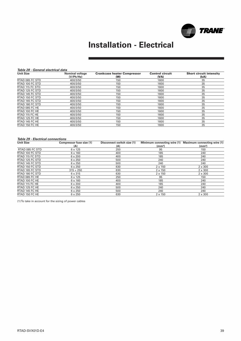
Installation - Electrical
RTAD-SVX01D-E4 39
Table 28 - General electrical data Unit Size Nominal voltage Crankcase heater Compressor Control circuit Short circuit intensity
(V/Ph/Hz) (W) (VA) (kA)RTAD 085 FC STD 400/3/50 150 1600 35RTAD 100 FC STD 400/3/50 150 1600 35RTAD 115 FC STD 400/3/50 150 1600 35RTAD 125 FC STD 400/3/50 150 1600 35RTAD 145 FC STD 400/3/50 150 1600 35RTAD 150 FC STD 400/3/50 150 1600 35RTAD 165 FC STD 400/3/50 150 1600 35RTAD 180 FC STD 400/3/50 150 1600 35RTAD 085 FC HE 400/3/50 150 1600 35RTAD 100 FC HE 400/3/50 150 1600 35RTAD 115 FC HE 400/3/50 150 1600 35RTAD 125 FC HE 400/3/50 150 1600 35RTAD 145 FC HE 400/3/50 150 1600 35RTAD 150 FC HE 400/3/50 150 1600 35
Table 29 - Electrical connections Unit Size Compressor fuse size (1) Disconnect switch size (1) Minimum connecting wire (1) Maximum connecting wire (1)
(A) (A) (mm²) (mm²)
RTAD 085 FC STD 6 x 125 250 95 150RTAD 100 FC STD 6 x 160 400 185 240RTAD 115 FC STD 6 x 200 400 185 240RTAD 125 FC STD 6 x 250 500 240 240RTAD 145 FC STD 6 x 250 500 240 240RTAD 150 FC STD 6 x 250 630 2 x 150 2 x 300 RTAD 165 FC STD 315 + 250 630 2 x 150 2 x 300 RTAD 180 FC STD 6 x 315 630 2 x 150 2 x 300 RTAD 085 FC HE 6 x 125 250 95 150RTAD 100 FC HE 6 x 160 400 185 240RTAD 115 FC HE 6 x 200 400 185 240RTAD 125 FC HE 6 x 250 500 240 240RTAD 145 FC HE 6 x 250 500 240 240RTAD 150 FC HE 6 x 250 630 2 x 150 2 x 300
(1) To take in account for the sizing of power cables
40 RTAD-SVX01D-E4
Installation - Electrical
Power Supply WiringAll power supply wiring must besized and selected accordingly by theproject engineer in accordance withEN 60204.WARNING! To prevent injury or
death, disconnect all electrical power
sources before completing wiring
connections to the unit.
All wiring must comply with CEelectrical codes. The installing (orelectrical) contractor must provideand install the systeminterconnecting wiring and thepower supply wiring. It must beproperly sized and equipped with theappropriate fused disconnectswitches. The type and installationlocation(s) of the fused disconnectsmust comply with all applicablecodes.CAUTION! Use only copper
conductors for terminal connections
to avoid corrosion or overheating.
Cut holes into the sides of thecontrol panel for the appropriatelysized power wiring conduits.The wiring is passed through theseconduits and connected to theterminal blocks, optional unit-mounted disconnects, or circuitbreakers. To provide proper phasing of 3-phaseinput, make connections as shown infield wiring diagrams and as statedon the Warning label in the starterpanel. For additional information onproper phasing, refer to "Unit VoltagePhasing." Proper equipment groundmust be provided to each groundconnection in the panel (one for eachcustomer-supplied conductor perphase).
Control Power Supply
The unit is equipped with a controlpower transformer; it is notnecessary to provide additionalcontrol power voltage to the unit. TheRTAD units are factory-connected for400V/3/50 with a factory-installedcontrol power transformer.
Heater Power Supply
The evaporator shell is insulatedfrom ambient air and protected fromfreezing temperatures by electricheaters. A heater also protects theheat recovery condenser(s).Whenever the air temperature dropsto approximately 37°F (2.8°C), thethermostat energizes the heaters.The heaters will provide protectionfrom ambient temperatures down to-18°C (0°F). The heaters are factory-wired back to the unit control panel.As an option, the heater will beenergized by a thermostat when thetemperature drops to approximately3°C.CAUTION! Control panel main
processor does not check for loss of
power to the heat tape nor does it
verify thermostat operation. A
qualified technician must verify
power to the heat tape and confirm
operation of the heat tape
thermostat to avoid catastrophic
damage to the evaporator.
Water Pump Power Supply
Provide power supply wiring withfused disconnect for the chilledwater pump(s).
1. As standard, all units have singlepoint power connection.
2. LRA (Locked Rotor Amps) - basedon full winding (x-line) start units.LRA for wye-delta starters is 1/3 ofLRA of x-line units.
3. VOLTAGE UTILIZATION RANGE:
Rated Voltage Utilization Range 400/50/3 340-460
For the RTAD 100 only, the UtilizationRange is 360 - 460 Volts
Installer-Supplied
ComponentsCAUTION! Customer wiring interface
connections are shown in the
electrical schematics and connection
diagrams that are shipped with the
unit.The installer must provide the
following components if not ordered
with the unit:
❏ Power supply wiring (in conduit)for all field-wired connections.
❏ All control (interconnecting) wiring(in conduit) for field supplieddevices.
❏ Fused-disconnect switches orcircuit breakers.
❏ Power factor correction capacitors.
RTAD-SVX01D-E4 41
Installation - Electrical
Interconnecting WiringChilled Water Flow (Pump) Interlock
The model RTAD chiller requires afield-supplied control voltage contactinput through a flow proving switch6S56 and an auxilary contact 6K51 ofthe chilled water pump contactor.IMPORTANT: Do not turn the chiller
on or off using the chilled-water
interlocks.
When making field connections,refer to the appropriate field layout,wiring schematics, and controldiagrams that ship with the unit.
Chilled-water pump control
CAUTION! The chilled-water pump
must operate for a minimum of one
minute after the UCM-CLD receives a
command, through the external
Auto/Stop input, to shut down the
chilled-water system.
On the RTAD units, the controller willinitiate the "Run:Unload" mode toterminate a cycle from any of thefollowing:• Stop key pressed• Loss of load• External Auto/Stop input openedThe "Run:Unload" operating modecommands the compressor tocompletely unload, which takesabout ½ minute. This will allow thecompressors to be totally unloadedfor the next start-up. If only theproof-of-chilled-water-flow interlockis used, the chiller will shut downwith an immediate (non-friendly)shutdown and initiate an automaticreset diagnostic.
1. External Auto/Stop (terminalsA1TB3-3 and -4). This input issupplied by the field. A contactclosure will start the chiller waterpump and chiller, via the UCM-CLDpump control contacts. Openingthe contact will put the operatingcompressors into "Run:Unload"mode and initiate a timing period(1 to 30 minutes, adjustablethrough the Clear LanguageDisplay). This will delaytermination of the chilled-waterpump operation via the UCMpump control contacts. Examplesof the input terminals 1UTB3-3and -4 would be a time clock,ambient thermostat, buildingautomation system, etc.
2. UCM-CLD Pump Control Contacts(Terminals A1 TB4-8 and -9)
This output is a set of contacts thatwill close, starting the chilled-waterpump when the external Auto/Stopcontacts are closed. When thecontacts are opened, 1 to 30 minuteslater (adjustable through the ClearLanguage Display), the UCM-CLDpump control contacts open.3. Proof-of-Chilled-Water-Flow
Interlock (Terminals A1 TB3-1and -2)
This terminal must be field-installed.Contact closure between theterminals indicates proof of chilled-water flow. Examples of this are apump starter auxiliary contact, flowswitch, differential pressure switch,or a contact from a buildingautomation system. Opening of thiscontact will immediately shut downthe chiller and initiate an automaticreset diagnostic, indicating loss ofchilled-water flow.

42 RTAD-SVX01D-E4
Installation - Electrical
Specification for Free Cooling units:
1. External Auto/Stop (terminals A70J8-IDH14 and 6X2-1). This input is supplied by the field. Acontact closure will start the chillerwater pump and chiller, via the UCM-CLD and A70 (regulation for FreeCooling mode) pump controlcontacts. Opening the contact willput the operating compressors into"Run:Unload" mode and initiate atiming period (1 to 30 minutes,adjustable through the ClearLanguage Display). This will delaytermination of the chilled-waterpump operation via the UCM pumpcontrol contacts. Examples of theinput terminals 1UTB3-3 and -4would be a time clock, ambientthermostat, building automationsystem, etc. 2. UCM-CLD and A 70 Pump Control
Contacts (Terminals A70 J14-C7and -NO7) This output is a set of contacts thatwill close, starting the chilled-water pump when the externalAuto/Stop contacts are closed.When the contacts are opened,1 to 30 minutes later (adjustablethrough the Clear LanguageDisplay), the UCM-CLD and A70pump control contacts open.
3. Proof-of-Chilled-Water-FlowInterlock (Terminals A70 J18-IDC13and -ID13H)This terminal must be field-installed. Contact closure betweenthe terminals indicates proof ofchilledwater flow. Examples of thisare a pump starter auxiliarycontact, flow switch, differentialpressure switch, or a contact froma building automation system.Opening of this contact willimmediately shut down the chillerand initiate an automatic resetdiagnostic, indicating loss ofchilled-water flow.
4. Free Cooling enable input(terminals A70 J5-IDI and 6X2-4).This input is supplied by the field.This is a digital input that indicatesif the Free Cooling mode isvalidated, or if only theCompressor mode must run. If thisinput is open, then only theCompressor mode will beavailable. If this input is close,then the control will select the bestmode (Free Cooling mode orCompressor mode).
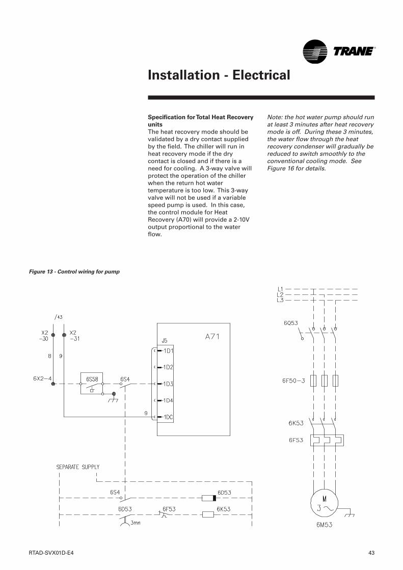
RTAD-SVX01D-E4 43
Installation - Electrical
Figure 13 - Control wiring for pump
Specification for Total Heat Recovery
units
The heat recovery mode should bevalidated by a dry contact suppliedby the field. The chiller will run inheat recovery mode if the drycontact is closed and if there is aneed for cooling. A 3-way valve willprotect the operation of the chillerwhen the return hot watertemperature is too low. This 3-wayvalve will not be used if a variablespeed pump is used. In this case,the control module for HeatRecovery (A70) will provide a 2-10Voutput proportional to the waterflow.
Note: the hot water pump should runat least 3 minutes after heat recoverymode is off. During these 3 minutes,the water flow through the heatrecovery condenser will gradually bereduced to switch smoothly to theconventional cooling mode. SeeFigure 16 for details.
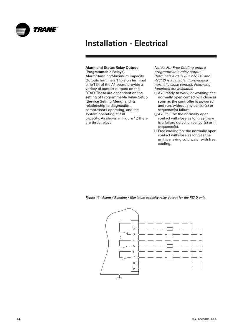
44 RTAD-SVX01D-E4
Installation - Electrical
Alarm and Status Relay Output
(Programmable Relays)
Alarm/Running/Maximum CapacityOutputs Terminals 1 to 7 on terminalstrip TB4 of the A1 board provide avariety of contact outputs on theRTAD. These are dependent on thesetting of Programmable Relay Setup(Service Setting Menu) and itsrelationship to diagnostics,compressors operating, and thesystem operating at fullcapacity. As shown in Figure 17, thereare three relays.
Notes: For Free Cooling units aprogrammable relay output(terminals A70 J17-C12-NO12 and -NC12) is available. It provides anormally close contact. Followingfunctions are available:❏ A70 ready to work, or working: the
normally open contact will close assoon as the controller is poweredand run, without any sensor(s) orsequence(s) failure.
❏ A70 failure: the normally opencontact will close as long as thereis a failure detect on sensor(s) or insequence(s).
❏ Free cooling on: the normally opencontact will close as long as theunit is making cold water with freecooling.
Figure 17 - Alarm / Running / Maximum capacity relay output for the RTAD unit.
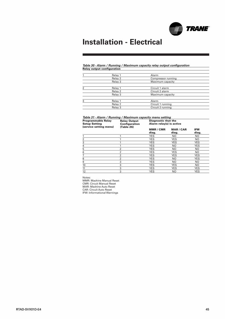
RTAD-SVX01D-E4 45RTAD-SVX01D-E4 45
Installation - Electrical
Table 30 - Alarm / Running / Maximum capacity relay output configuration Relay output configuration
1 Relay 1 AlarmRelay 2 Compressor runningRelay 3 Maximum capacity
2 Relay 1 Circuit 1 alarmRelay 2 Circuit 2 alarmRelay 3 Maximum capacity
3 Relay 1 AlarmRelay 2 Circuit 1 runningRelay 3 Circuit 2 running
Table 31 - Alarm / Running / Maximum capacity menu setting
1 1 YES NO NO2 1 YES YES NO3 1 YES YES YES4 1 YES NO YES5 2 YES NO NO6 2 YES YES NO7 2 YES YES YES8 2 YES NO YES9 3 YES NO NO10 3 YES YES NO11 3 YES YES YES12 3 YES NO YES
Notes:MMR: Machine Manual ResetCMR: Circuit Manual ResetMAR: Machine Auto ResetCAR: Circuit Auto ResetIFW: Informational Warnings
Diagnostic that theAlarm relay(s) is active
Programmable RelaySetup Setting (service setting menu)
Relay OutputConfiguration(Table 26)
MMR / CMR diag.
MAR / CARdiag.
IFW diag.

46 RTAD-SVX01D-E4
Installation - Electrical
External Emergency stop
(normal trip)The Clear Language Display providesauxiliary control for a customer-specified or -installed latchingtripout. When this remote contact6S2 (furnished by the customer) isprovided, the chiller will runnormally when the contact is closed.When the contact opens, the unit willtrip off on a manually resettablediagnostic. This condition requiresmanual reset at the chiller switch onthe front of the Clear LanguageDisplay. To connect, first remove thejumper located between terminal 3and 4 of A1 TB1. Refer to the fielddiagrams that are shipped with theunit.
External Auto/StopIf the unit requires the externalAuto/Stop function, the installermust provide leads from theremote contacts 6S1 to the properterminals of the module A1 (to A70for Free-cooling units) terminalsTB3-3 and TB3-4 (J8-IDH14 and 6X2-1for Free cooling/Heat Recoveryunits), in the control panel.The chiller will run normally whenthe contact is closed. When thecontact opens, the compressor(s), ifoperating, will go to theRUN:UNLOAD operating mode andcycle off. Unit operation will beinhibited. Re-closure of the contactswill permit the unit to automaticallyreturn to normal operation. Field-supplied contacts for all low voltageconnections must be compatiblewith dry circuit 24VDC for a 12 mAresistive load. Refer to the fielddiagrams that are shipped with theunit.
External circuit lockout -
Circuit 1The UCM provides auxiliary controlof a customer-specified or -installedcontact closure, for individualoperation of circuit number 1. If thecontact is closed, the refrigerantcircuit will not operate. Therefrigerant circuit will run normallywhen the contact is opened. Externalcircuit lockout will only function ifExternal Circuit Lockout (servicesetting Menu) is enabled.Connections are shown in the fielddiagrams that are shipped with theunit.
External circuit lockout -
Circuit 2The UCM provides auxiliary controlof a customer-specified or -installedcontact closure, for individualoperation of circuit number 2. If thecontact is closed, the refrigerantcircuit will not operate. Therefrigerant circuit will run normallywhen the contact is opened. Externalcircuit lockout will only function ifExternal Circuit Lockout (servicesetting Menu) is enabled.Connections are shown in the fielddiagrams that are shipped with theunit.
Low-voltage wiringThe remote devices described belowrequire low-voltage wiring. All wiringto and from these remote analogdevices to the UCM-CLD (and A70 forFree cooling/Heat Recovery units), asdescribed in this paragraph, must bemade with shielded, twisted-pairconductors. Be sure to ground theshielding only at the Clear LanguageDisplay.CAUTION! To prevent control
malfunction, do not run low-voltage
wiring (<30V) in conduits with
conductors carrying more than 30 V.
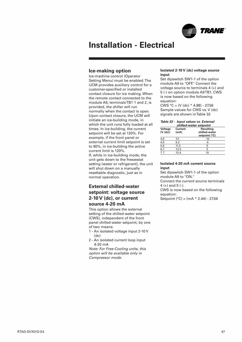
RTAD-SVX01D-E4 47
Installation - Electrical
Ice-making optionIce-machine control (OperatorSetting Menu) must be enabled. TheUCM provides auxiliary control for acustomer-specified or installedcontact closure for ice making. Whenthe remote contact connected to themodule A9, terminals TB1 1 and 2, isprovided, the chiller will runnormally when the contact is open.Upon contact closure, the UCM willinitiate an ice-building mode, inwhich the unit runs fully loaded at alltimes. In ice-building, the currentsetpoint will be set at 120%. Forexample, if the front panel orexternal current limit setpoint is setto 80%, in ice-building the activecurrent limit is 120%.If, while in ice-building mode, theunit gets down to the freezestatsetting (water or refrigerant), the unitwill shut down on a manuallyresettable diagnostic, just as innormal operation.
External chilled-water
setpoint: voltage source
2-10 V (dc), or current
source 4-20 mAThis option allows the externalsetting of the chilled-water setpoint(CWS), independent of the frontpanel chilled-water setpoint, by oneof two means:1 - An isolated voltage input 2-10 V
(dc)2 - An isolated current loop input
4-20 mANote: For Free-Cooling units, thisoption will be available only inCompressor mode.
Isolated 2-10 V (dc) voltage source
input
Set dipswitch SW1-1 of the optionmodule A9 to "OFF." Connect thevoltage source to terminals 4 (+) and5 (-) on option module A9 TB1. CWSis now based on the followingequation:CWS °C = (V (dc) * 4.88) - 27.56Sample values for CWS vs. V (dc)signals are shown in Table 32
Table 32 - Input values vs. Externalchilled-water setpoint
Voltage Current(V (dc)) (mA)
3.6 7.2 -104.6 9.2 -55.6 11.3 06.7 13.3 57. 7 15.4 10
Isolated 4-20 mA current source
input
Set dipswitch SW1-1 of the optionmodule A9 to "ON." Connect the current source terminals4 (+) and 5 (-).CWS is now based on the followingequation:Setpoint (°C) = (mA * 2.44) - 27.56
Resultingchilled-watersetpoint (°C)
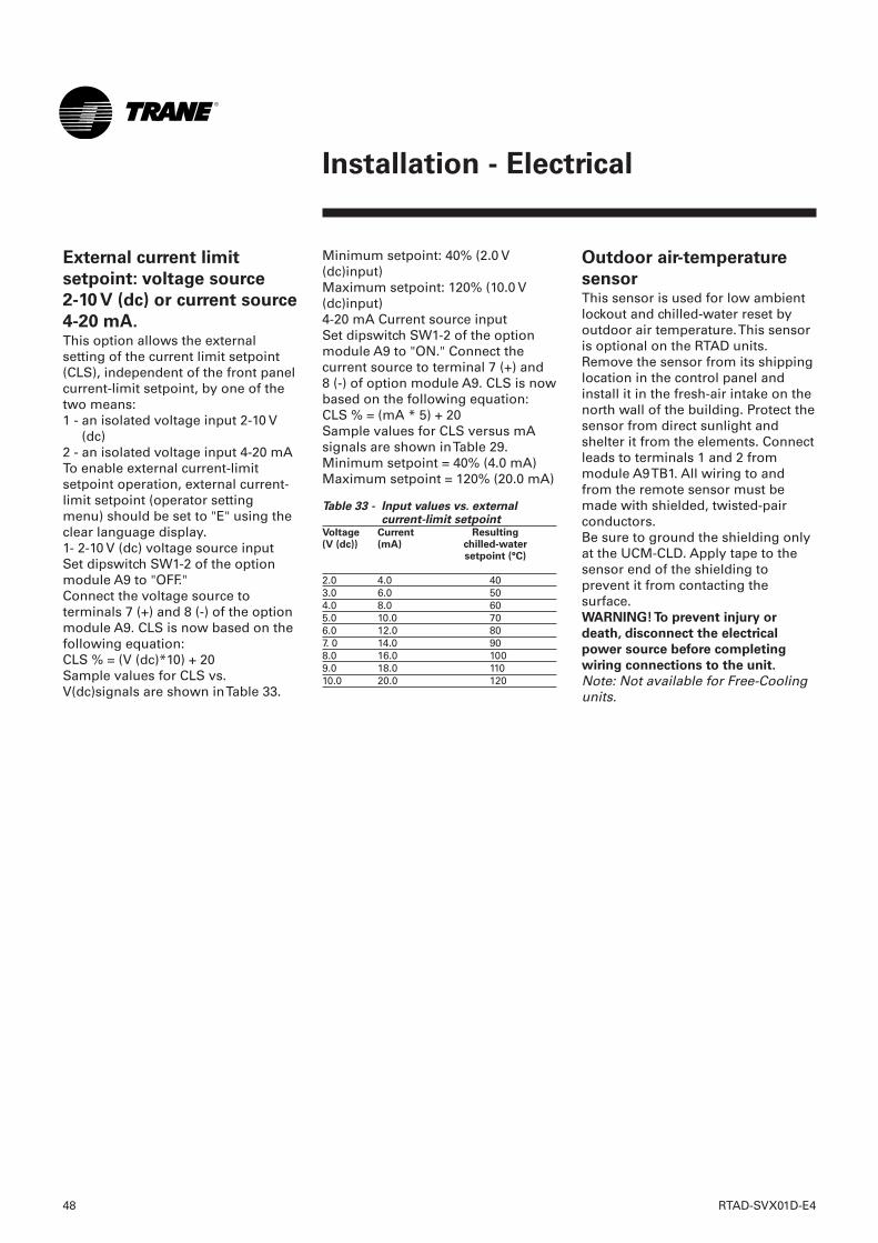
48 RTAD-SVX01D-E4
Installation - Electrical
Minimum setpoint: 40% (2.0 V(dc)input)Maximum setpoint: 120% (10.0 V(dc)input)4-20 mA Current source inputSet dipswitch SW1-2 of the optionmodule A9 to "ON." Connect thecurrent source to terminal 7 (+) and8 (-) of option module A9. CLS is nowbased on the following equation:CLS % = (mA * 5) + 20Sample values for CLS versus mAsignals are shown in Table 29.Minimum setpoint = 40% (4.0 mA)Maximum setpoint = 120% (20.0 mA)
Table 33 - Input values vs. externalcurrent-limit setpoint
Voltage Current(V (dc)) (mA)
2.0 4.0 403.0 6.0 504.0 8.0 605.0 10.0 706.0 12.0 807. 0 14.0 908.0 16.0 1009.0 18.0 11010.0 20.0 120
Outdoor air-temperature
sensorThis sensor is used for low ambientlockout and chilled-water reset byoutdoor air temperature. This sensoris optional on the RTAD units.Remove the sensor from its shippinglocation in the control panel andinstall it in the fresh-air intake on thenorth wall of the building. Protect thesensor from direct sunlight andshelter it from the elements. Connectleads to terminals 1 and 2 frommodule A9 TB1. All wiring to andfrom the remote sensor must bemade with shielded, twisted-pairconductors.Be sure to ground the shielding onlyat the UCM-CLD. Apply tape to thesensor end of the shielding toprevent it from contacting thesurface.WARNING! To prevent injury or
death, disconnect the electrical
power source before completing
wiring connections to the unit.
Note: Not available for Free-Coolingunits.
External current limit
setpoint: voltage source
2-10 V (dc) or current source
4-20 mA.This option allows the externalsetting of the current limit setpoint(CLS), independent of the front panelcurrent-limit setpoint, by one of thetwo means:1 - an isolated voltage input 2-10 V
(dc)2 - an isolated voltage input 4-20 mATo enable external current-limitsetpoint operation, external current-limit setpoint (operator settingmenu) should be set to "E" using theclear language display.1- 2-10 V (dc) voltage source input Set dipswitch SW1-2 of the optionmodule A9 to "OFF." Connect the voltage source toterminals 7 (+) and 8 (-) of the optionmodule A9. CLS is now based on thefollowing equation: CLS % = (V (dc)*10) + 20Sample values for CLS vs.V(dc)signals are shown in Table 33.
Resultingchilled-watersetpoint (°C)
CAUTION! To prevent overheating at
the terminal connections, use copper
conductors only.
Communication card CSRThis option allows the ClearLanguage Display in the controlpanel on RTAD units to exchangeinformation (operating setpoints andAuto/Standby commands) with ahigher-level control device, such asTracer. A shielded, twisted-pairconnection establishes thebidirectional communications linkbetween the unit control panel andthe Tracer.Note: The shielded, twisted-pairconductors must run in a separateconduit.CAUTION! To prevent control
malfunction, do not run low-voltage
wiring (<30V) in conduits with
conductors carrying more than
30 volts.
Field wiring for the communicationlink must meet the followingrequirements:1. All wiring must be in accordance
with local codes.2. Communication link wiring must
be shielded, twisted-pair wiring.3. The maximum total length for
each communication link is1,500 meters.
4. The communication link cannotpass between buildings.
5. All UCM-CLD on thecommunication link can beconnected in a "daisy chain"configuration.
Communication-link
connection procedure1. Refer to the Tracer installation
literature to determine propercommunication-link terminationconnections at the Tracer module.
2. Connect the shield of thecommunication-link wiring to thedesignated shield terminal at theTracer module.
3. Connect leads to terminals 1 to 4of TB2 of the module A9 of theUCM-CLD to the Tracer. There is nopolarity requirement for theconnection.
4. At the UCM-CLD, the shield shouldbe cut and taped to prevent anycontact between the shield andground.
Note: On multiple-unit installations,splice the shielding of the twistedpairs that come into each UCM-CLDin the "daisy chain" system. Tape thespliced connections to prevent anycontact between the shield andground. At the last Clear LanguageDisplay in the chain, the shieldshould be cut and taped off.5. To get the chiller to communicate
with a Tracer on a multiple-unitcontroller, the ICS address underthe "service settings" menu mustbe set and the optional A9 modulemust be installed. Contact yourlocal Trane representative for thismatter.
RTAD-SVX01D-E4 49
Installation - Electrical
50 RTAD-SVX01D-E4
Installation - Electrical
Network variables
LonTalk uses network variables tocommunicate points on acommunication link. LonMark hasdefined a list of standard networkvariables.
Chiller Functional Profile
LonMark calls their standard list ofvariables for chiller control theChiller Functional Profile. This profileis meant to allow interoperabilitybetween control systems andchillers, regardless of chiller type ormanufacturer.
The LCI-C Extension
The LCI-C Extension is a list ofadditional network variables Tranecreated that are over and above theones defined by the ChillerFunctional Profile. The LCI-CExtension is considered "open"because the network variables arenot proprietary. The networkvariables in the LCI-C Extension aredefined in the "User defined types"section.
LCI-C shipment and inspection
The LCI-C is either factory-installedwith the chiller controller or shippedas an individual part for fieldinstallation.
Storage
If the LCI-C is stored for a period oftime prior to being installed, it mustbe protected from the elements. Thetemperature of the storage locationshould be between -40 °C and 70 °Cand the relative humidity should be0-95%, non-condensing.
Communications
The Tracer LCI-C controllercommunicates via Trane's LonTalkprotocol. Typically, a communicationlink is applied between unitcontrollers and a buildingautomation system. Communicationalso is possible via Rover servicetool. Peer-to-peer communicationacross controllers is possible evenwhen a building automation systemis not present.You do not need to observe polarityfor LonTalk communication links.The LonTalk communicationsprotocol allows peer to peercommunications betweencontrollers, which allows controllersto share information or data. Acommunicated variable input such assetpoint, space temperature, oroutdoor air temperature has priorityover a locally wired input to thecontroller.Example: if the LCI-C controller has awired outdoor air temperaturesensor and Tracer Summit or anotherLonTalk controller sends it acommunicated outdoor airtemperature, the communicatedvalue is used by the LCI-C controller.If a communicated input value islost, the LCI-C controller reverts tousing the locally wired sensor input.
Device Addressing
LonTalk devices are given a uniqueaddress by the manufacturer. Thisaddress is called a Neuron ID. EachLCI-C controller can be identified byits unique Neuron ID, which isprinted on a label on the controller.The Neuron ID is also displayedwhen communication is establishedusing Tracer Summit or Rover servicetool. The Neuron ID format is 00-01-64-1C- 2B-00.
LonTalk® Communications
Interface for Chillers (LCI-C)The unit controller provides anoptional LonTalk CommunicationInterface (LCI-C) between the chillerand a Building Automation System(BAS). An LCI-C LLID shall be used toprovide "gateway" functionalitybetween a LonTalk compatibledevice and the chiller. Theinputs/outputs include bothmandatory and optional networkvariables as established by theLonMark Functional Chiller Profile8040.This section introduces the LCI-Cdevice for RTAD. For furtherinformation please refer to themanual ACC-SVN32A-EN.
If you are connecting the LCI-C to aTracer Summit™ system, you willnot need the network variableinformation given in this part.If you are connecting the LCI-C to anon-Trane building automationsystem using LonTalk™, AppendixesA through B will provide you withthe system integration informationyou will need regarding networkvariables.
LonMark certification
The LonMark organization promotesLonTalk as an industry standard forcontrol communication. The LCI-C iscertified to the LonMark ChillerFunctional Profile 8040 Version 1.0,and follows LonTalk FTT-10Acommunications system technology.Compliance with this technologymeans that the LCI-C can provide aninterface for non-Trane LonTalknetworks.
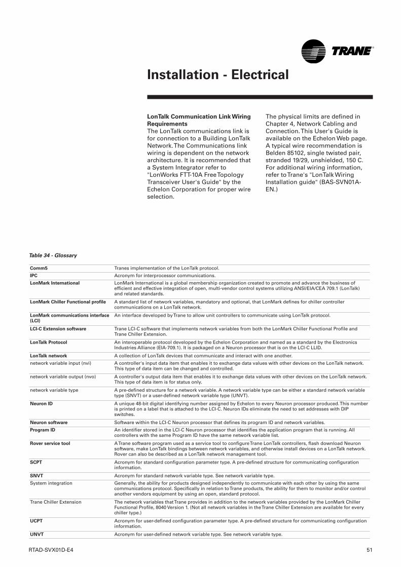
RTAD-SVX01D-E4 51
Installation - Electrical
LonTalk Communication Link Wiring
Requirements
The LonTalk communications link isfor connection to a Building LonTalkNetwork. The Communications linkwiring is dependent on the networkarchitecture. It is recommended thata System Integrator refer to"LonWorks FTT-10A Free TopologyTransceiver User's Guide" by theEchelon Corporation for proper wireselection.
The physical limits are defined inChapter 4, Network Cabling andConnection. This User's Guide isavailable on the Echelon Web page. A typical wire recommendation isBelden 85102, single twisted pair,stranded 19/29, unshielded, 150 C.For additional wiring information,refer to Trane's "LonTalk WiringInstallation guide" (BAS-SVN01A-EN.)
Table 34 - Glossary
Comm5 Tranes implementation of the LonTalk protocol.
IPC Acronym for interprocessor communications.
LonMark International LonMark International is a global membership organization created to promote and advance the business ofefficient and effective integration of open, multi-vendor control systems utilizing ANSI/EIA/CEA 709.1 (LonTalk)and related standards.
LonMark Chiller Functional profile A standard list of network variables, mandatory and optional, that LonMark defines for chiller controllercommunications on a LonTalk network.
LonMark communications interface(LCI)
An interface developed by Trane to allow unit controllers to communicate using LonTalk protocol.
LCI-C Extension software Trane LCI-C software that implements network variables from both the LonMark Chiller Functional Profile andTrane Chiller Extension.
LonTalk Protocol An interoperable protocol developed by the Echelon Corporation and named as a standard by the ElectronicsIndustries Alliance (EIA-709.1). It is packaged on a Neuron processor that is on the LCI-C LLID.
LonTalk network A collection of LonTalk devices that communicate and interact with one another.
network variable input (nvi) A controller's input data item that enables it to exchange data values with other devices on the LonTalk network.This type of data item can be changed and controlled.
network variable output (nvo) A controller's output data item that enables it to exchange data values with other devices on the LonTalk network.This type of data item is for status only.
network variable type A pre-defined structure for a network variable. A network variable type can be either a standard network variabletype (SNVT) or a user-defined network variable type (UNVT).
Neuron ID A unique 48-bit digital identifying number assigned by Echelon to every Neuron processor produced. This numberis printed on a label that is attached to the LCI-C. Neuron IDs eliminate the need to set addresses with DIPswitches.
Neuron software Software within the LCI-C Neuron processor that defines its program ID and network variables.
Program ID An identifier stored in the LCI-C Neuron processor that identifies the application program that is running. Allcontrollers with the same Program ID have the same network variable list.
Rover service tool A Trane software program used as a service tool to configure Trane LonTalk controllers, flash download Neuronsoftware, make LonTalk bindings between network variables, and otherwise install devices on a LonTalk network.Rover can also be described as a LonTalk network management tool.
SCPT Acronym for standard configuration parameter type. A pre-defined structure for communicating configurationinformation.
SNVT Acronym for standard network variable type. See network variable type.
System integration Generally, the ability for products designed independently to communicate with each other by using the samecommunications protocol. Specifically in relation to Trane products, the ability for them to monitor and/or controlanother vendors equipment by using an open, standard protocol.
Trane Chiller Extension The network variables that Trane provides in addition to the network variables provided by the LonMark ChillerFunctional Profile, 8040 Version 1. (Not all network variables in the Trane Chiller Extension are available for everychiller type.)
UCPT Acronym for user-defined configuration parameter type. A pre-defined structure for communicating configurationinformation.
UNVT Acronym for user-defined network variable type. See network variable type.
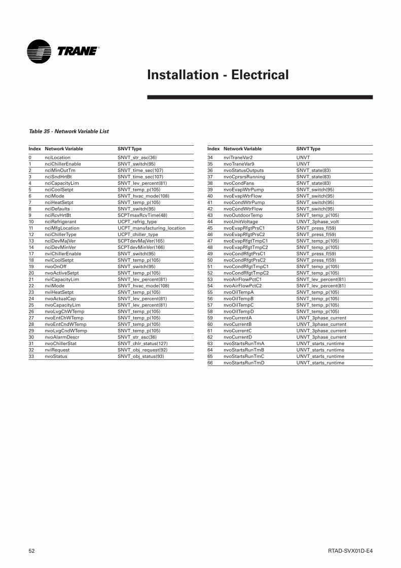
52 RTAD-SVX01D-E4
Installation - Electrical
Index Network Variable SNVT Type
0 nciLocation SNVT_str_asc(36) 1 nciChillerEnable SNVT_switch(95) 2 nciMinOutTm SNVT_time_sec(107) 3 nciSndHrtBt SNVT_time_sec(107) 4 nciCapacityLim SNVT_lev_percent(81) 5 nciCoolSetpt SNVT_temp_p(105) 6 nciMode SNVT_hvac_mode(108) 7 nciHeatSetpt SNVT_temp_p(105) 8 nciDefaults SNVT_switch(95) 9 nciRcvHrtBt SCPTmaxRcvTime(48) 10 nciRefrigerant UCPT_refrig_type 11 nciMfgLocation UCPT_manufacturing_location 12 nciChillerType UCPT_chiller_type 13 nciDevMajVer SCPTdevMajVer(165) 14 nciDevMinVer SCPTdevMinVer(166) 17 nviChillerEnable SNVT_switch(95) 18 nviCoolSetpt SNVT_temp_p(105) 19 nvoOnOff SNVT_switch(95) 20 nvoActiveSetpt SNVT_temp_p(105) 21 nviCapacityLim SNVT_lev_percent(81) 22 nviMode SNVT_hvac_mode(108) 23 nviHeatSetpt SNVT_temp_p(105) 24 nvoActualCap SNVT_lev_percent(81) 25 nvoCapacityLim SNVT_lev_percent(81) 26 nvoLvgChWTemp SNVT_temp_p(105) 27 nvoEntChWTemp SNVT_temp_p(105) 28 nvoEntCndWTemp SNVT_temp_p(105) 29 nvoLvgCndWTemp SNVT_temp_p(105) 30 nvoAlarmDescr SNVT_str_asc(36) 31 nvoChillerStat SNVT_chlr_status(127) 32 nviRequest SNVT_obj_request(92) 33 nvoStatus SNVT_obj_status(93)
Index Network Variable SNVT Type
34 nviTraneVar2 UNVT 35 nvoTraneVar9 UNVT 36 nvoStatusOutputs SNVT_state(83) 37 nvoCprsrsRunning SNVT_state(83) 38 nvoCondFans SNVT_state(83) 39 nvoEvapWtrPump SNVT_switch(95) 40 nvoEvapWtrFlow SNVT_switch(95) 41 nvoCondWtrPump SNVT_switch(95) 42 nvoCondWtrFlow SNVT_switch(95) 43 nvoOutdoorTemp SNVT_temp_p(105) 44 nvoUnitVoltage UNVT_3phase_volt 45 nvoEvapRfgtPrsC1 SNVT_press_f(59) 46 nvoEvapRfgtPrsC2 SNVT_press_f(59) 47 nvoEvapRfgtTmpC1 SNVT_temp_p(105) 48 nvoEvapRfgtTmpC2 SNVT_temp_p(105) 49 nvoCondRfgtPrsC1 SNVT_press_f(59) 50 nvoCondRfgtPrsC2 SNVT_press_f(59) 51 nvoCondRfgtTmpC1 SNVT_temp_p(105) 52 nvoCondRfgtTmpC2 SNVT_temp_p(105) 53 nvoAirFlowPctC1 SNVT_lev_percent(81) 54 nvoAirFlowPctC2 SNVT_lev_percent(81) 55 nvoOilTempA SNVT_temp_p(105) 56 nvoOilTempB SNVT_temp_p(105) 57 nvoOilTempC SNVT_temp_p(105) 58 nvoOilTempD SNVT_temp_p(105) 59 nvoCurrentA UNVT_3phase_current 60 nvoCurrentB UNVT_3phase_current 61 nvoCurrentC UNVT_3phase_current 62 nvoCurrentD UNVT_3phase_current 63 nvoStartsRunTmA UNVT_starts_runtime 64 nvoStartsRunTmB UNVT_starts_runtime 65 nvoStartsRunTmC UNVT_starts_runtime 66 nvoStartsRunTmD UNVT_starts_runtime
Table 35 - Network Variable List
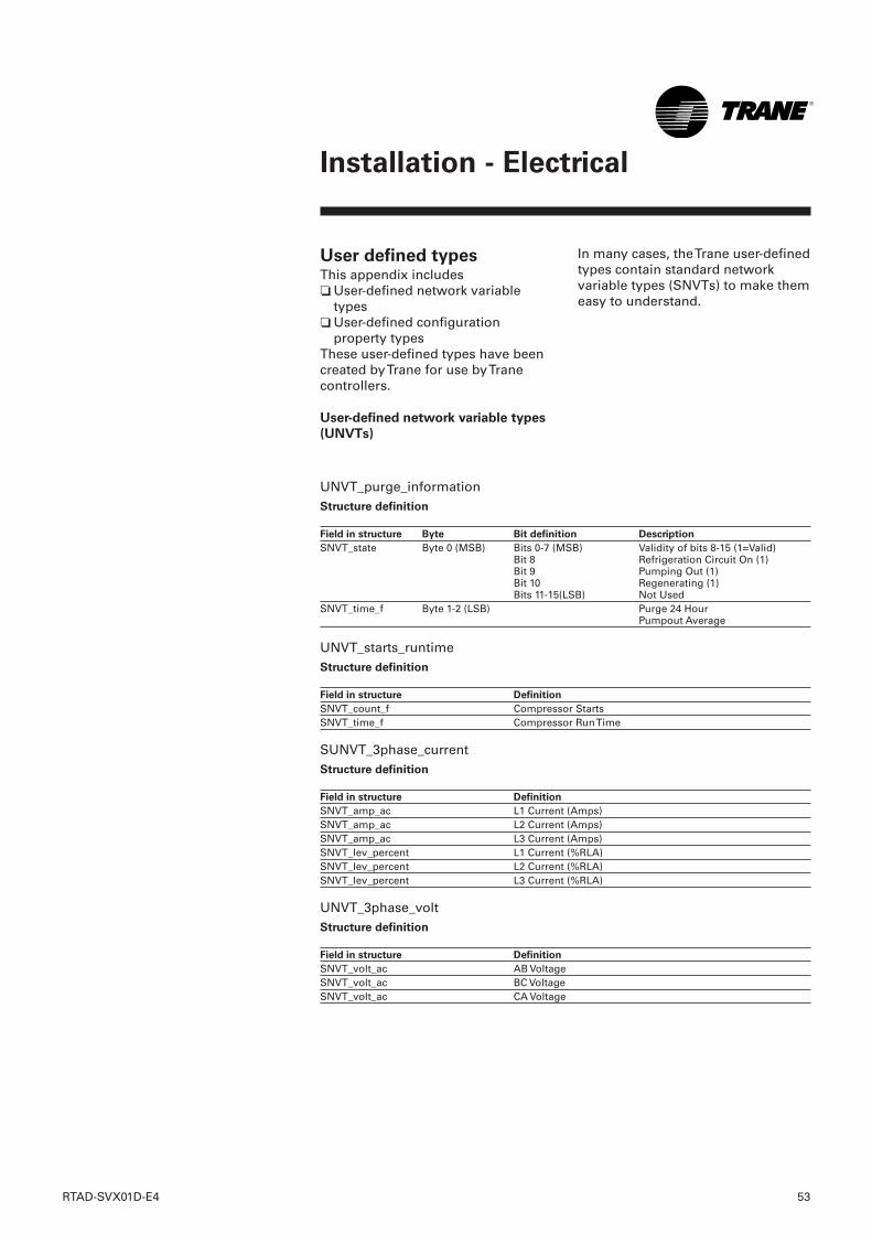
RTAD-SVX01D-E4 53
Installation - Electrical
In many cases, the Trane user-definedtypes contain standard networkvariable types (SNVTs) to make themeasy to understand.
User defined typesThis appendix includes❏ User-defined network variable
types❏ User-defined configuration
property typesThese user-defined types have beencreated by Trane for use by Tranecontrollers.
User-defined network variable types
(UNVTs)
UNVT_purge_informationStructure definition
Field in structure Byte Bit definition Description
SNVT_state Byte 0 (MSB) Bits 0-7 (MSB) Validity of bits 8-15 (1=Valid)Bit 8 Refrigeration Circuit On (1)Bit 9 Pumping Out (1) Bit 10 Regenerating (1) Bits 11-15(LSB) Not Used
SNVT_time_f Byte 1-2 (LSB) Purge 24 Hour Pumpout Average
UNVT_starts_runtimeStructure definition
Field in structure Definition
SNVT_count_f Compressor Starts SNVT_time_f Compressor Run Time
SUNVT_3phase_currentStructure definition
Field in structure Definition
SNVT_amp_ac L1 Current (Amps) SNVT_amp_ac L2 Current (Amps) SNVT_amp_ac L3 Current (Amps) SNVT_lev_percent L1 Current (%RLA) SNVT_lev_percent L2 Current (%RLA) SNVT_lev_percent L3 Current (%RLA)
UNVT_3phase_voltStructure definition
Field in structure Definition
SNVT_volt_ac AB Voltage SNVT_volt_ac BC Voltage SNVT_volt_ac CA Voltage
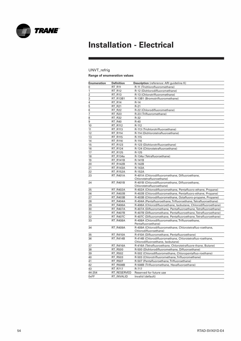
54 RTAD-SVX01D-E4
Installation - Electrical
UNVT_refrigRange of enumeration values
Enumeration Definition Description (reference: ARI guideline K) 0 RT_R11 R-11 (Trichlorofluoromethane) 1 RT_R12 R-12 (Dichlorodifluoromethane) 2 RT_R13 R-13 (Chlorotrifluoromethane) 3 RT_R13B1 R-13B1 (Bromotrifluoromethane) 4 RT_R14 R-14 5 RT_R21 R-21 6 RT_R22 R-22 (Chlorodifluoromethane) 7 RT_R23 R-23 (Trifluoromethane) 8 RT_R32 R-32 9 RT_R40 R-40 10 RT_R112 R-112 11 RT_R113 R-113 (Trichlorotrifluoroethane) 12 RT_R114 R-114 (Dichlorotetrafluoroethane) 13 RT_R115 R-115 14 RT_R116 R-116 15 RT_R123 R-123 (Dichlorotrifluoroethane) 16 RT_R124 R-124 (Chlorotetrafluoroethane) 17 RT_R125 R-125 18 RT_R134a R-134a (Tetrafluoroethane) 19 RT_R141B R-141B 20 RT_R142B R-142B 21 RT_R143A R-143A 22 RT_R152A R-152A 23 RT_R401A R-401A (Chlorodifluoromethane, Difluoroethane,
Chlorotetrafluoroethane) 24 RT_R401B R-401B (Chlorodifluoromethane, Difluoroethane,
Chlorotetrafluoroethane) 25 RT_R402A R-402A (Chlorodifluoromethane, Pentafluoro-ethane, Propane) 26 RT_R402B R-402B (Chlorodifluoromethane, Pentafluoro-ethane, Propane) 27 RT_R403B R-403B (Chlorodifluoromethane, Octafluoro-propane, Propane) 28 RT_R404A R-404A (Pentafluoroethane, Trifluoroethane, Tetrafluoroethane) 29 RT_R406A R-406A (Chlorodifluoroethane, Isobutane, Chlorodifluoroethane) 30 RT_R407A R-407A (Difluoromethane, Pentafluoroethane, Tetrafluoroethane) 31 RT_R407B R-407B (Difluoromethane, Pentafluoroethane, Tetrafluoroethane) 32 RT_R407C R-407C (Difluoromethane, Pentafluoroethane, Tetrafluoroethane) 33 RT_R408A R-408A (Chlorodifluoromethane, Trifluoroethane,
Pentafluoroethane) 34 RT_R409A R-409A (Chlorodifluoromethane, Chlorotetrafluo-roethane,
Chlorodifluoroethane) 35 RT_R410A R-410A (Difluoromethane, Pentafluoroethane) 36 RT_R414B R-414B (Chlorodifluoromethane, Chlorotetrafluo-roethane,
Chlorodifluoroethane, Isobutane) 37 RT_R416A R-416A (Tetrafluoroethane, Chlorotetrafluore-thane, Butane) 38 RT_R500 R-500 (Dichlorodifluoromethane, Difluoroethane) 39 RT_R502 R-502 (Chlorodifluoromethane, Chloropentafluo-roethane) 40 RT_R503 R-503 (Chlorotrifluoromethane, Trifluoromethane) 41 RT_R507 R-507 (Pentafluoroethane, Trifluoroethane) 42 RT_R508B R-508B (Trifluoromethane, Hexafluoroethane) 43 RT_R717 R-717 44-254 RT_RESERVED Reserved for future use 0xFF RT_INVALID Invalid (default)
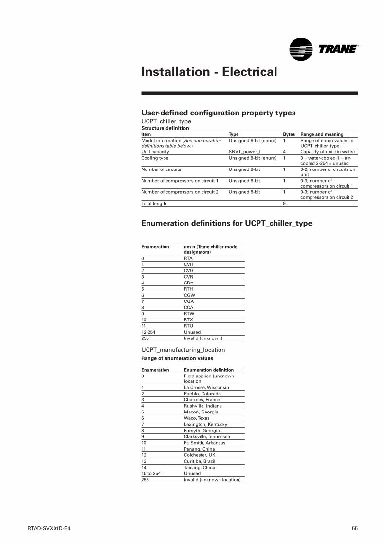
RTAD-SVX01D-E4 55
Installation - Electrical
Enumeration um n (Trane chiller modeldesignators)
0 RTA 1 CVH 2 CVG 3 CVR 4 CDH 5 RTH 6 CGW 7 CGA 8 CCA 9 RTW 10 RTX 11 RTU 12-254 Unused 255 Invalid (unknown)
UCPT_manufacturing_locationRange of enumeration values
Enumeration Enumeration definition
0 Field applied (unknownlocation)
1 La Crosse, Wisconsin 2 Pueblo, Colorado 3 Charmes, France 4 Rushville, Indiana 5 Macon, Georgia 6 Waco, Texas 7 Lexington, Kentucky 8 Forsyth, Georgia 9 Clarksville, Tennessee 10 Ft. Smith, Arkansas 11 Penang, China 12 Colchester, UK 13 Curitiba, Brazil 14 Taicang, China 15 to 254 Unused 255 Invalid (unknown location)
User-defined configuration property typesUCPT_chiller_typeStructure definition
Item Type Bytes Range and meaning
Unsigned 8-bit (enum) 1 Range of enum values inUCPT_chiller_type
Unit capacity SNVT_power_f 4 Capacity of unit (in watts) Cooling type Unsigned 8-bit (enum) 1 0 = water-cooled 1 = air-
cooled 2-254 = unused Number of circuits Unsigned 8-bit 1 0-2; number of circuits on
unit Number of compressors on circuit 1 Unsigned 8-bit 1 0-3; number of
compressors on circuit 1 Number of compressors on circuit 2 Unsigned 8-bit 1 0-3; number of
compressors on circuit 2 Total length 9
Enumeration definitions for UCPT_chiller_type
Model information (See enumerationdefinitions table below.)
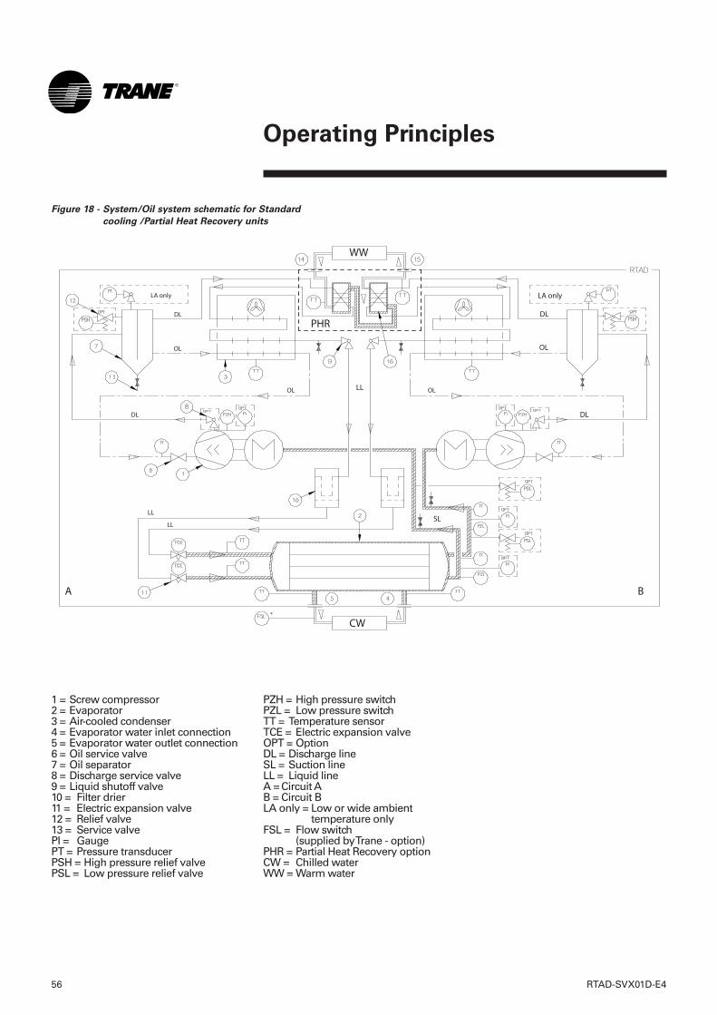
56 RTAD-SVX01D-E4
PZH = High pressure switchPZL = Low pressure switchTT = Temperature sensorTCE = Electric expansion valveOPT = OptionDL = Discharge lineSL = Suction lineLL = Liquid lineA = Circuit AB = Circuit BLA only = Low or wide ambient
temperature onlyFSL = Flow switch
(supplied by Trane - option)PHR = Partial Heat Recovery optionCW = Chilled waterWW = Warm water
1 = Screw compressor2 = Evaporator3 = Air-cooled condenser4 = Evaporator water inlet connection5 = Evaporator water outlet connection6 = Oil service valve7 = Oil separator8 = Discharge service valve9 = Liquid shutoff valve10 = Filter drier11 = Electric expansion valve12 = Relief valve13 = Service valvePI = GaugePT = Pressure transducerPSH = High pressure relief valvePSL = Low pressure relief valve
Operating Principles
Figure 18 - System/Oil system schematic for Standard
cooling /Partial Heat Recovery units
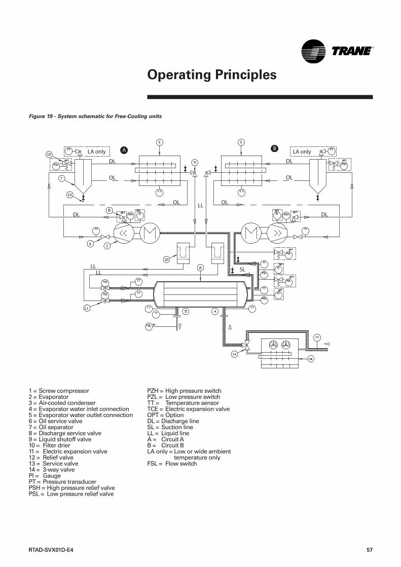
PZH = High pressure switchPZL = Low pressure switchTT = Temperature sensorTCE = Electric expansion valveOPT = OptionDL = Discharge lineSL = Suction lineLL = Liquid lineA = Circuit AB = Circuit BLA only = Low or wide ambient
temperature onlyFSL = Flow switch
1 = Screw compressor2 = Evaporator3 = Air-cooled condenser4 = Evaporator water inlet connection5 = Evaporator water outlet connection6 = Oil service valve7 = Oil separator8 = Discharge service valve9 = Liquid shutoff valve10 = Filter drier11 = Electric expansion valve12 = Relief valve13 = Service valve14 = 3-way valvePI = GaugePT = Pressure transducerPSH = High pressure relief valvePSL = Low pressure relief valve
RTAD-SVX01D-E4 57RTAD-SVX01D-E4 57
Operating Principles
Figure 19 - System schematic for Free-Cooling units
DL
OL
DL
OL
DL
SLLLLL
DL
OL
A B
OLLL
LA only LA only
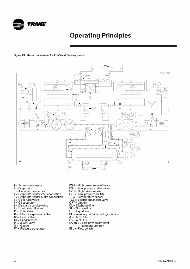
58 RTAD-SVX01D-E4
Operating Principles
Figure 20 - System schematic for Total Heat Recovery units
LL
1 = Screw compressor2 = Evaporator3 = Air-cooled condenser4 = Evaporator water inlet connection5 = Evaporator water outlet connection6 = Oil service valve7 = Oil separator8 = Discharge service valve9 = Liquid shutoff valve10 = Filter drier11 = Electric expansion valve12 = Relief valve13 = Service valve14 = 3-way valvePI = GaugePT = Pressure transducer
PSH = High pressure relief valvePSL = Low pressure relief valvePZH = High pressure switchPZL = Low pressure switchTT = Temperature sensorTCE = Electric expansion valveOPT = OptionDL = Discharge lineSL = Suction lineLL = Liquid lineRL = Auxiliary oil cooler refrigerant lineA = Circuit AB = Circuit BLA only = Low or wide ambient
temperature onlyFSL = Flow switch
RTAD-SVX01D-E4 59
Pre-Start Checkout
Unit Piping❏ Flush all unit water piping before
making final connections to theunit.
CAUTION! If using an acidic
commercial flushing solution,
construct a temporary bypass
around the unit to prevent damage
to internal components of the
evaporator.To avoid possible
equipment damage, do not use
untreated or improperly treated
system water.
❏ Connect the chilled water piping tothe evaporator.
Note: On Free-Cooling units, thechilled water piping will beconnected to the evaporator on oneside and to the 3-way valve on theother side (see Figure 19)❏ Install pressure gauges and shutoff
valves on the chilled water inletand outlet to the evaporator.
❏ Install a water strainer in theentering chilled water line.
❏ Install a balancing valve and flowswitch (recommended) in theleaving chilled water line.
❏ Install a drain with shutoff valve ora drain plug on the evaporatorwaterbox.
❏ Vent the chilled water system athigh points in the system piping.
❏ Apply heat tape and insulation, asnecessary, to protect all exposedpiping from freeze-up.
PHR/THR units
❏ Ensure that the heat recoverywater piping is ready to operate,filled with water and air purged.
❏ Ensure that a water strainer isinstalled.
❏ Check the position ofthermometers and manometers.
Electrical Wiring WARNING! To prevent injury or
death, disconnect electrical power
source before completing wiring
connections to the unit.
CAUTION! To avoid corrosion and
overheating at terminal connections,
use copper conductors only.
❏ Connect the unit power supplywiring with fused-disconnect tothe terminal block or lugs (or unit-mounted disconnect) in the powersection of the control panel.
❏ Connect power supply wiring tothe evaporator heater.
❏ Connect power supply wiring tothe chilled water pump.
❏ Connect power supply wiring toany auxiliary heat tapes.
❏ Connect the auxiliary contact ofthe chilled water pump (6K51) inseries with the flow switch, ifinstalled, and then connect to theproper terminals.
❏ For the External Auto/Stopfunction, install wiring fromremote contact (6S1) to the properterminals on the circuit board.
Note: On Free-Cooling units, for freecooling enable output, install wiringfrom remote contact (6S3) to theproper terminals on the circuitboard.CAUTION! Information in
Interconnecting Wiring: Chilled Water
Pump Interlock and External
Auto/Stop must be adhered to or
equipment damage may occur.
Heat Recovery units
❏ Ensure that the Heat Recoverymode input is correctly wired (drycontact)
❏ Check that the hot water pump hasa 3 minute time delay after theHeat Recovery mode is switchedoff.
Installation ChecklistComplete this checklist as the unit isinstalled and verify that allrecommended procedures areaccomplished before the unit isstarted. This checklist does notreplace the detailed Instructionsgiven in the "Installation -Mechanical" and "Installation -Electrical" sections of this manual.Read both sections completely, tobecome familiar with the installationprocedures, prior to beginning thework.
Receiving❏ Verify that the unit nameplate data
corresponds to the orderinginformation.
❏ Inspect the unit for shippingdamage and any shortages ofmaterials. Report any damage orshortage to the carrier.
Unit Location and
Mounting❏ Inspect the location desired for
installation and verify adequateservice access clearances.
❏ Provide drainage for evaporatorwater.
❏ Remove and discard all shippingmaterials (cartons, etc.)
❏ Install optional rubber isolators, ifrequired.
❏ Level the unit and secure it to themounting surface.
3 Check the power supply voltage tothe unit at the main power fused-disconnect switch. Voltage must bewithin the voltage utilization rangeand also stamped on the unitnameplate. Voltage imbalancemust not exceed 3%.
4 Check the unit power phasing L1-L2-L3 in the starter to be sure thatit has been installed in an "ABC"phase sequence.
CAUTION! Improper power phasing
can result in equipment damage due
to reverse rotation.
CAUTION! Do not use untreated or
improperly treated water.
Equipment damage may occur.
5 Fill the evaporator chilled watercircuit. Vent the system while it isbeing filled. Open the vents on thetop of the evaporator shell whilefilling and close when filling iscompleted.
Important:The use of improperly
treated or untreated water in this
equipment may result in scaling,
erosion, corrosion, algae or slime.
The services of a qualified water
treatment specialist should be
engaged to determine what
treatment, if any, is advisable.Trane
warranty specifically excludes
liability of corrosion, erosion or
deterioration of Trane equipment.
Trane assumes no responsibilities for
the results of the use of untreated or
improperly treated water or saline or
brackish water.
6 Close the fused-disconnectswitch(es) that supplies power tothe chilled water pump starter.
7 Start the chilled water pump tobegin circulation of the water.Inspect all piping for leakage andmake any necessary repairs.
8 With water circulating through thesystem, adjust water flow andcheck water pressure drop throughthe evaporator.
9 Adjust the chilled water flow switchfor proper operation.
WARNING! Use extreme caution
when performing the following
procedure with power applied.
Failure to do so can result in
personal injury or death.
10 Reapply power to completeprocedures.
11 Prove all Interlock andInterconnecting Wiring Interlockand External as described in theElectrical Installation section.
12 Check and set, as required, allUCM-CLD menu items.
Note: On Total Heat Recovery andFree-Cooling units, also check andset the A70 module.13 Stop the chilled water pump.14 Energize compressor and oil
separators 24 hours prior to unitstart-up.
❏ If alarm and status relay outputsare used, install leads from thepanel to the proper terminals oncircuit board.
❏ If the emergency stop function isused, install low voltage leads toterminals on circuit board.
❏ Connect separate power for theExternal Emergency Stop option, ifapplicable.
❏ If the ice making-option is used,install leads on terminals TB1-1and 2 on module A9.
GeneralWhen installation is complete, butprior to putting the unit into service,the following pre-startprocedures must be reviewed andverified correct:WARNING! Disconnect all electric
power including remote disconnects
before servicing. Failure to
disconnect power before servicing
can cause severe personal injury or
death.
1 Inspect all wiring connections inthe compressor power circuits(disconnects, terminal block,contactors, compressor junctionbox terminals, etc.). to be sure theyare clean and tight.
CAUTION! Verify all connections are
made. Loose connections can cause
overheating and undervoltage
conditions at the compressor motor.
2 Open all refrigerant valves in thedischarge, liquid, oil and oil returnlines.
CAUTION! Do not operate the unit
with the compressor, oil discharge,
liquid line service valves and the
manual shutoff on the refrigerant
supply to the coolers "CLOSED".
Failure to have these "OPEN" may
cause serious compressor damage.
60 RTAD-SVX01D-E4
Pre-Start Checkout
RTAD-SVX01D-E4 61
Pre-Start Checkout
CAUTION! Provide adequate voltage
to the unit. Failure to do so can
cause control components to
malfunction and shorten the life of
relay contact, compressor motors
and contactors.
CAUTION! Power supply with TT or
TN earthing arrangement is not
compatible with IT (Insulated
Neutral) earthing arrangement.
Unit Voltage ImbalanceExcessive voltage imbalancebetween the phases of three-phasesystem can cause motors tooverheat and eventually fail. Themaximum allowable imbalance is3 percent. Voltage imbalance isdetermined using the followingcalculations:
% Imbalance = [(Vx - V ave) x
100]/Vave
V ave = (V1 + V2 + V3)/3
Vx = phase with the greatest
difference from V ave (without
regard to the sign)
For example, if the three measured
voltages are 221, 230, and 227 volts,
the average would be:
(221+230+227)/3 = 226
The percentage of the imbalance is
then:
[100 * (221-226)] / 226 = 2.2%
This exceeds the maximum
allowable (2%) by 0.2 percent.
Unit Voltage PhasingWARNING! It is imperative that L1,
L2, L3 in the starter be connected in
the A-B-C phase sequence to prevent
equipment damage due to reverse
rotation.
It is important that proper rotation ofthe compressors be establishedbefore the unit is started.Proper motor rotation requiresconfirmation of the electrical phasesequence of the power supply. Themotor is internally connected forclockwise rotation with the incomingpower supply phased A, B, C.Basically, voltages generated in eachphase of a polyphase alternator orcircuit are called phase voltages. Ina three-phase circuit, three sine wavevoltages are generated, differing inphase by 120 electrical degrees. Theorder in which the three voltages of athree-phase system succeed oneanother is called phase sequence orphase rotation. This is determined bythe direction of rotation of thealternator. When rotation isclockwise, phase sequence is usuallycalled "ABC," when counter-clockwise, "CBA."This direction may be reversedoutside the alternator byinterchanging any two of the linewires. It is this possible interchangeof wiring that makes a phasesequence indicator necessary if theoperator is to quickly determine thephase rotation of the motor.
Unit Voltage Power SupplyVoltage to the unit must meet thecriteria given in the Installation-Electrical Section. Measure each legof the supply voltage at the unit'smain power fused- disconnect. If themeasured voltage on any leg is notwithin specified range, notify thesupplier of the power and correct thesituation before operating the unit.
Proper compressor motor electricalphasing can be quickly determinedand corrected before starting theunit. Use a quality instrument, suchas the Associated Research Model 45Phase Sequence Indicator, andfollow this procedure.1 Press the STOP key on the UCM-
CLD.2 Open the electrical disconnect or
circuit protection switch thatprovides line power to the linepower terminal block(s) in thestarter panel (or to the unit-mounted disconnect).
3 Connect the phase sequenceindicator leads to the line Powerterminal block, as follows:
Phase Sequence Lead Terminal
Black (Phase A) L1
Red (Phase B) L2
Yellow (Phase C) L3
4 Turn power on by closing the unitsupply power fused-disconnectswitch.
5 Read the phase sequence on theindicator. The "ABC" LED on theface of the phase indicator willglow if phase is "ABC."
WARNING! To prevent injury or
death due to electrocution, take
extreme care when performing
service procedures with electrical
power energized.
6 If the "CBA" indicator glowsinstead, open the unit main powerdisconnect and switch two lineleads on the line power terminalblock(s) (or the unit mounteddisconnect). Reclose the mainpower disconnect and recheck thephasing.
CAUTION! Do not interchange any
load leads that are from the unit
contactors or the motor terminals.
Doing so may damage the
equipment.
7 Reopen the unit disconnect anddisconnect the phase indicator.
Water System Flow Rates Establish a balanced chilled waterflow through the evaporator. Theflow rates should fall between theminimum and maximum valuesgiven on the pressure drop curves.Chilled water flow rates below theminimum values will result inlaminar flow, which reduces heattransfer and causes either loss ofEXV control or repeated nuisance,low temperature, cutouts. Flow ratesthat are too high can cause tubedamage in the evaporator.
Water System Pressure
DropMeasure water pressure dropthrough the evaporator at the field-installed pressure taps on the systemwater piping. Use the same gaugefor each measurement. Do notinclude valves, strainers fittings inthe pressure drop readings.Pressure drop readings should beapproximately those shown in thepressure drop charts in theInstallation - Mechanical section.
62 RTAD-SVX01D-E4
Pre-Start Checkout
RTAD-SVX01D-E4 63
Unit Start-up Procedures
For Free Cooling units only:
At power up, the unit will chooseeither if it should start in Free-Cooling mode or in Compressormode through the CarelTM module:• If only Free-Cooling is available,
then Free-Cooling mode will beentered immediately at this time.
• If only Compressor mode isavailable, then Compressor modewill be entered immediately at thistime.
• If both modes are available, thenthe mode to enter will depend on afew conditions. If ( (Leaving WaterTemperature) - (Active ChilledWater Setpoint) > 2 * (Dead band) ),or if Free-Cooling coil cannotgenerate more than 5% of its delta Tat current conditions, then theCompressor mode will be enteredimmediately. If these conditions arefalse for at least 15 minutes, thenthe Free-Cooling mode will beentered immediately.
To allow the system to operate evenin case of failure on chiller or on freecooling side, a menu allows theservice technician to choose betweenthe following modes:❏ Auto mode:This is the default
mode. If enable by external Free-Cooling Enable input (FCE), thesoftware will choose between Free-Cooling mode or Compressormode. If disable by FCE, theCompressor mode will always beenabled. In auto mode the RTADFree-Cooling unit will always start-up in Compressor mode and thenif conditions to pass in Free-Cooling mode are verified for atleast 15 minutes, the Free-Coolingmode will be enabled.
❏ Compressor mode only:
Compressor mode will always beenabled.
❏ Free-cooling mode only: Free-Cooling will always be enabled.This will allow service oncompressor side of the unit.
WARNING! This menu will enable
function made by the software, but
service technician must remove all
power supply before servicing parts,
especially on moving dangerous
devices.
Daily Unit Start-UpThe time line for sequence ofoperation is shown at the end of thissection and depicts the nominaldelays and sequences that a chillerwould experience during a typicaloperational cycle. The time linebegins with a power up of the mainpower to the chiller. The sequenceassumes a RTAD chiller with nodiagnostics or malfunctioningcomponents. External events such asthe operator placing the chiller inAuto or Stop, chilled water flowthrough the evaporator, andapplication of load to the chilledwater loop causing loop watertemperature increases are depictedand the chillers responses to thoseevents are shown, with appropriatedelays noted. The effects ofdiagnostics, and other externalinterlocks other than evaporatorwater flow proving, are notconsidered. The response of the CLDDisplay is also depicted on the timeline.
CAUTION! To prevent compressor
damage, do not operate the unit
until all refrigerant and oil line
service valves are opened.
5 Verify that the chilled water pumpruns for at least one minute afterthe chiller is commanded to stop(for normal chilled water systems).
6 Press the AUTO key. If the chillercontrol calls for cooling and allsafety interlocks are closed, theunit will start. The compressor(s)will load and unload in response tothe leaving chilled watertemperature.
Once the system has been operatingfor approximately 30 minutes andhas become stabilized, complete theremaining start-up procedures, asfollows:1 Check the evaporator refrigerant
pressure and the condenserrefrigerant pressure underRefrigerant Report on the CLDModule. The pressures arereferenced to sea level (1013 mbar -14.7 psia).
2 Measure the system dischargesuperheat.
3 Measure the system subcooling.
4 A shortage of refrigerant isindicated if operating pressures arelow and subcooling is also low. Ifthe operating pressures, sightglass, superheat and subcoolingreadings indicate a refrigerantshortage, gas-charge refrigerantinto each circuit, as required. Withthe unit running, add refrigerantvapor by connecting the chargingline to the suction charging servicevalve port until operatingconditions become normal.
CAUTION! If both suction and
discharge pressures are low but
subcooling is normal, a problem
other than refrigerant shortage
exists. Do not add refrigerant, as this
may result in overcharging the
circuit. Use only refrigerants
specified on the unit nameplate (HFC
134a) and Trane Oil 00048. Failure to
do so may cause compressor
damage and improper unit
operation.
Note: On Free-Cooling units, inCompressor mode, the procedurewill remain the same. In FreeCooling mode, only point 1 needs tobe checked, as the compressors arenot running. To release more coolingcapacity and reduce pressure drop,Trane recommends using 50%nominal water flow while in FreeCooling mode.
GeneralIf the pre-start checkout, as discussedabove, has been completed, the unitis ready to start.1 Press the STOP key on the CLD
module.2 As necessary, adjust the setpoint
values in the UCM-CLD « OperatorSettings » menu.
3 Close the fused-disconnect switchfor the chilled water pump.Energize the pump(s) to start watercirculation.
4 Check the service valves on thedischarge line, oil line and liquidline for each circuit. These valvesmust be open (backseated) beforestarting the compressors.
64 RTAD-SVX01D-E4
Unit Start-up Procedures
RTAD-SVX01D-E4 65
Unit Start-up Procedures
Seasonal Unit Start-Up
Procedure1 Close all valves and re-install the
drain plugs in the evaporator.2 Service the auxiliary equipment
according to the start-up/maintenance instructionsprovided by the respectiveequipment manufacturers.
3 Close the vents in the evaporatorchilled water circuits.
4 Open all the valves in theevaporator chilled water circuits.
5 Open all refrigerant valves to verifythey are in the open condition.
6 If the evaporator was previouslydrained, vent and fill theevaporator and chilled watercircuit. When all air is removedfrom the system , re-install the ventplugs on top of the evaporatorshell.
CAUTION! Ensure that the
compressor and oil separator
heaters have been operating for a
minimum of 24 hours before
starting. Failure to do so may result
in equipment damage.
7 Check the adjustment andoperation of each safety andoperating control.
8 Close all disconnect switches.9 Refer to the sequence for daily unit
startup for the remainder of theseasonal startup.
System Restart After
Extended ShutdownFollow the procedures below torestart the unit after extendedshutdown:1 Verify that the liquid line service
valves, oil line, compressordischarge service valves (whensupplied) are open (backseated).
CAUTION! To prevent damage to the
compressor, be sure that all
refrigerant valves are open before
starting the unit.
2 Check the oil separator oil level(see Maintenance Proceduressection).
3 Fill the evaporator water circuit.Vent the system while it is beingfilled. Open the vent on the top ofthe evaporator while filling andclose when filling is completed.
CAUTION! Do not used untreated or
improperly treated water.
Equipment damage may occur.
4 Close the fused-disconnectswitches that provides power tothe chilled water pump.
5 Start the evaporator water pumpand, while water is circulating,inspect all piping for leakage. Makeany necessary repairs beforestarting the unit.
6 While the water is circulating,adjust the water flows and checkthe water pressure drops throughthe evaporator. Refer to "WaterSystem Flow Rates" and "WaterSystem Pressure Drop".
7 Adjust the flow switch on theevaporator piping for properoperation.
8 Stop the water pump. The unit isnow ready for start-up as describedin "Start-Up Procedures".
Temporary Shutdown And
RestartTo shut the unit down for a shorttime, use the following procedure:1 Press the STOP key on the UCM-
CLD. The compressors willcontinue to operate and, afterunloading for 20 seconds, will stopwhen the compressor contactorsde-energize.
Note: On Free-Cooling units in FreeCooling mode, only the fans willstop. In Compressor mode, there isno change.2 Stop the water circulation by
turning off the chilled water pump.To restart the unit after a temporaryshutdown, enable the chilled waterpump and press the AUTO key. Theunit will start normally, providedthe following conditions exist:
❏ The control module receives a callfor cooling and the differential-to-start is above the setpoint.
❏ All system operating interlocksand safety circuits are satisfied.
Extended Shutdown
ProcedureThe following procedure is to befollowed if the system is to be takenout of service for anextended period of time, e.g.seasonal shutdown:1 Test the unit for refrigerant leaks
and repair as necessary.2 Open the electrical disconnect
switches for the chilled waterpump. Lock the switches in the"OPEN" position.
CAUTION! Lock the chilled water
pump disconnect Switch in the
"OPEN" position, to prevent pump
damage.
3 Close all chilled water supplyvalves. Drain the water from theevaporator.
4 Open the unit main electricaldisconnect and unit-mounteddisconnect (if installed) and lock onthe "OPEN" position.
CAUTION! Lock the disconnects in
the "OPEN" position to prevent
accidental start-up and damage to
the system when it has been setup
for extended shutdown.
5 At least every three months(quarterly), check the refrigerantpressure in the unit to verify thatthe refrigerant charge is intact.
Note: For Free-Cooling units, checkthe percentage of ethylene glycol inthe water circuit in order to protectagainst freeze-up.
66 RTAD-SVX01D-E4
Unit Shutdown Procedures
RTAD-SVX01D-E4 67
Maintenance
Weekly MaintenanceWhile unit is running in stableconditions.1 Check UCM-CLD pressure for
Evaporator, Condenser and Oil.2 The subcooling should never be
less than 3°C (5.4°F) under anycircumstances.
CAUTION! A clear sightglass alone
does not mean that the system is
properly charged. Also check rest of
system operating conditions.
3 Inspect the entire system forunusual conditions and inspect thecondenser coils for dirt and debris.If the coils are dirty, refer to coilcleaning.
Note: On Free-Cooling units, the FreeCooling coil has to be checked too.
Monthly Maintenance1 Perform all weekly maintenance
procedures.2 Record the system subcooling.3 Record the system superheat.4 Make any repairs necessary.
Annual Maintenance1 Perform all weekly and monthly
procedures.2 Check oil sump oil level while unit
is off.Note: Routine changing of the oil isnot required. Use an oil analysis todetermine the condition of the oil.3 Have a qualified laboratory
perform a compressor oil analysisto determine system moisturecontent and acid level. Thisanalysis is a valuable diagnostictool.
4 Contact a qualified serviceorganization to leak test the chiller,to check operating and safetycontrols, and to inspect electricalcomponents for deficiencies.
5 Inspect all piping components forleakage and damage. Clean outany inline strainers.
6 Clean and repaint any areas thatshow signs of corrosion.
7 Clean the condenser coils.WARNING! Position all electrical
disconnects in the "Open" position
and lock them to prevent injury or
death due to electrical shock.
Note: On Free-Cooling units, the FreeCooling coil has to be checked too.8 Check and tighten all electrical
connections as necessary.
GeneralPerform all maintenance proceduresand inspections at the recommendedintervals. This will prolong the life ofthe chiller and minimize thepossibility of costly failures. Recordan operating history for the unit,which will serve as a valuablediagnostic tool for service personnel.By observing trends in operatingconditions, an operator cananticipate and prevent problemsituations before they occur. Afterthe unit has been operating forapproximately 30 minutes and thesystem has stabilized, check theoperating conditions and completethe procedures below:
Refrigerant Emission
ControlConservation and emissionreduction can be accomplished byfollowing recommended Traneoperation, maintenance and serviceprocedures, with specific attention tothe following:1 Refrigerant used in any type of air
conditioning or refrigeratingequipment should be recovered forreuse, recovered and/or recycledfor reuse, or reprocessed(reclaimed). Never releaserefrigerant into the atmosphere.
2 Always determine possible recycleor reclaim requirements of therecovered refrigerant beforebeginning recovery by any method.
3 Use approved containment vesselsand safety standards. Comply withall applicable transportationstandards when shippingrefrigerant containers.
4 To minimize emissions whilerecovering refrigerant, userecycling equipment. Alwaysattempt to use methods which willpull the lowest possible vacuumwhile recovering and condensingrefrigerant into containment.
5 Refrigeration-system cleanupmethods that use filters and dryersare preferred. Do not use solventsthat have ozone depletion factors.Properly dispose of used materials.
6 Take extra care to properlymaintain all service equipment thatdirectly supports refrigerationservice work, such as gauges,hoses, vacuum pumps andrecycling equipment.
7 Stay aware of unit enhancements,conversion refrigerants,compatible parts andmanufacturer's recommendationswhich will reduce refrigerantemissions and increase equipmentoperating efficiencies. Followmanufacturer's specific guidelinesfor conversion of existing systems.
8 In order to assist in reducingpower-generation emissions,always attempt to improveequipment performance withimproved maintenance andoperations that will help conserveenergy resources.
All the air-cooled RTAD chillers aregiven a complete functional test atthe factory covering sensors, wiring,electrical components,microprocessor function,communication capability, expansionvalve performance and fans. Whereapplicable, each unit is factory presetto the customer's design conditions,including leaving water temperaturesetpoint, current limit, and resettemperature setpoint.
Note: Free-Cooling units are freeze-protected with 30% ethylene glycolin the cooling loop circuit which isthe most convenient percentage toprotect the unit against freeze-up.
Protection coverage with 30%ethylene glycol:- freezing point without burst effect =
-13°C- freezing point with burst effect =
- 50°CIt is necessary to regularly check thepercentage of ethylene glycol in thewater circuit (at least every threemonths).
68 RTAD-SVX01D-E4
Maintenance Procedures
RTAD-SVX01D-E4 69
Maintenance Procedures
Some symptoms of a refrigerant
over charged unit:
- High Subcooling- Larger than normal condenser
approach temperatures (EnteringCondenser Saturated Temperature -Entering Air Temperature)
- Condenser Pressure Limit- High Pressure Cutout diagnostic- More than normal number of fans
running- Erratic Fan Control- Higher than normal compressor
power- Very low discharge superheat at
startup- Compressor rattle or grinding
sound at startupSome symptoms of an oil over
charged unit:
- Larger than normal evaporatorapproach temperatures (LeavingWater Temperature -Saturated Evaporator Temperature)
- Low Evaporator RefrigerantTemperature Limit
- Low Refrigerant TemperatureCutout diagnostic
- Very erratic liquid level control- Low unit capacity- Low discharge superheat
(especially at high loads)- Compressor rattle or grinding
sound- High oil sump level after normal
shut downSome symptoms of an oil under
charged unit:
- Compressor rattle or grindingsound
- Lower than normal pressure dropthrough oil system
- Seized or Welded Compressors- Low oil sump level after normal
shut down- Lower than normal oil
concentrations in evaporator
R134a Field Charging
ProcedureBe certain that the electrical power tothe unit is disconnected beforeperforming this procedure.WARNING! Position all electrical
disconnects in the "OPEN" position
and lock them to prevent injury or
death due to electrocution.
Refrigerant ChargingIf the refrigerant charge needs to beadjusted, be certain to monitor thesubcooling and superheatmeasurements. The subcoolingneeds to be between 6°C (10°F) and12°C (20°F) when the unit is runningfully loaded. The ambienttemperature is between 24°C (75°F)and 38°C (100°F) and the leavingwater temperature is between 5°C(41°F) and 13°C (55°F).
Refrigerant and Oil Charge
ManagementProper oil and refrigerant charge isessential for proper unit operation,unit performance, andenvironmental protection. Onlytrained and licensed service personalshould service the chiller.Some symptoms of a refrigerant
under charged unit:
- Low Subcooling- Larger than normal evaporator
approach temperatures (LeavingWater Temperature -Saturated Evaporator Temperature)
- Low Evaporator RefrigerantTemperature Limit
- Low Refrigerant TemperatureCutout diagnostic
- Fully open expansion valve- Possible whistling sound coming
from liquid line (due to high vaporvelocity)
- Possible low discharge superheat athigh loads
- High Condenser + SubcoolerPressure drop
5 Once the compressor stops, closethe discharge service valve on thecompressor (this valve is optionalon RTAD).
6 The remaining refrigerant needs tobe recovered from the suction lineservice valve. Attach the inlet of arecovery system to the port of thecharging valve. Attach the outlet ofthe recovery system to themanifold gauge set that is alreadyattached to the access port on theliquid line service valve. Thecondenser will be used as astorage vessel.
7 Complete all necessary repairs.8 Evacuate out of the suction line
service charging valve.9 Break the vaccum by adding
refrigerant in the suction linethrough the service valve.
10 Open all valves, start the unit andverify the refrigerant charge bymeasuring the subcooling.
Isolating the refrigerant
charge in the low pressure
side for High Side RepairsIf the refrigerant charge needs to beisolated in the low side of the unit,perform the following procedures:1 Press the STOP key and send the
unit to a stopping mode.2 Close the discharge service valve
(optional on RTAD).3 Before closing the liquid line
service valve, attach a manifoldgauge set to the liquid linebackseat port.
4 Close the liquid line service valve.5 Attach the inlet of a liquid transfer
pump to the manifold gauge setand the outlet of the service valvemounted on the suction line.
This will transfer the liquidrefrigerant. As the low pressure sidecannot contain all the charge, theremaining refrigerant will betransferred to a separate vessel.6 Remove all of the vapor from the
high side of the system.7 Complete all necessary repairs.8 Evacuate the high side through the
access port on the liquid lineservice valve.
9 Open all the valves and run theunit. Verify the refrigerant chargeby measuring the subcooling.
Isolating the refrigerant
charge in the high pressure
side for Low Side Repairs.To perform this operation the unitmust be equipped with the optionaldischarge service valveIf the refrigerant charge needs to beisolated in the high side of the unit,perform the following procedures:1 Press the STOP key and send the
unit to a stopping mode.2 Place a manifold gauge set on the
backseat port of the liquid lineservive valve before actuallyclosing the valve.
3 Close the liquid line service valve.4 While the unit is in the STOP mode,
enable Service Pumpdown for thespecific compressor. ServicePumpdown is found under theService Tests menu of the UCM-CLD.
Note: Service Pumpdown can onlybe enabled for one compressor at atime. Only one pumpdown percompressor can be performed, untilthe unit has been reset. With Service Pumpdown enabled,the Restart inhibit will be ignored,the EXV will be prepositioned andthe selected compressor will startand run for one minute.
70 RTAD-SVX01D-E4
Maintenance Procedures
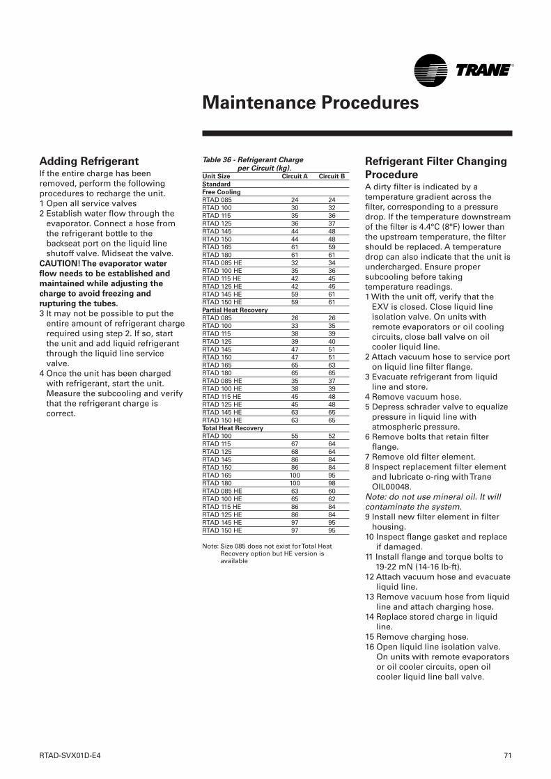
RTAD-SVX01D-E4 71
Maintenance Procedures
Table 36 - Refrigerant Charge per Circuit (kg).
Unit Size Circuit A Circuit B
Standard
Free Cooling
RTAD 085 24 24RTAD 100 30 32RTAD 115 35 36RTAD 125 36 37RTAD 145 44 48RTAD 150 44 48RTAD 165 61 59RTAD 180 61 61RTAD 085 HE 32 34RTAD 100 HE 35 36RTAD 115 HE 42 45RTAD 125 HE 42 45RTAD 145 HE 59 61RTAD 150 HE 59 61Partial Heat Recovery
RTAD 085 26 26RTAD 100 33 35RTAD 115 38 39RTAD 125 39 40RTAD 145 47 51RTAD 150 47 51RTAD 165 65 63RTAD 180 65 65RTAD 085 HE 35 37RTAD 100 HE 38 39RTAD 115 HE 45 48RTAD 125 HE 45 48RTAD 145 HE 63 65RTAD 150 HE 63 65Total Heat Recovery
RTAD 100 55 52RTAD 115 67 64RTAD 125 68 64RTAD 145 86 84RTAD 150 86 84RTAD 165 100 95RTAD 180 100 98RTAD 085 HE 63 60RTAD 100 HE 65 62RTAD 115 HE 86 84RTAD 125 HE 86 84RTAD 145 HE 97 95RTAD 150 HE 97 95
Note: Size 085 does not exist for Total HeatRecovery option but HE version isavailable
Refrigerant Filter Changing
ProcedureA dirty filter is indicated by atemperature gradient across thefilter, corresponding to a pressuredrop. If the temperature downstreamof the filter is 4.4°C (8°F) lower thanthe upstream temperature, the filtershould be replaced. A temperaturedrop can also indicate that the unit isundercharged. Ensure propersubcooling before takingtemperature readings.1 With the unit off, verify that the
EXV is closed. Close liquid lineisolation valve. On units withremote evaporators or oil coolingcircuits, close ball valve on oilcooler liquid line.
2 Attach vacuum hose to service porton liquid line filter flange.
3 Evacuate refrigerant from liquidline and store.
4 Remove vacuum hose.5 Depress schrader valve to equalize
pressure in liquid line withatmospheric pressure.
6 Remove bolts that retain filterflange.
7 Remove old filter element.8 Inspect replacement filter element
and lubricate o-ring with TraneOIL00048.
Note: do not use mineral oil. It willcontaminate the system.9 Install new filter element in filter
housing.10 Inspect flange gasket and replace
if damaged.11 Install flange and torque bolts to
19-22 mN (14-16 lb-ft).12 Attach vacuum hose and evacuate
liquid line.13 Remove vacuum hose from liquid
line and attach charging hose.14 Replace stored charge in liquid
line.15 Remove charging hose.16 Open liquid line isolation valve.
On units with remote evaporatorsor oil cooler circuits, open oilcooler liquid line ball valve.
Adding RefrigerantIf the entire charge has beenremoved, perform the followingprocedures to recharge the unit.1 Open all service valves2 Establish water flow through the
evaporator. Connect a hose fromthe refrigerant bottle to thebackseat port on the liquid lineshutoff valve. Midseat the valve.
CAUTION! The evaporator water
flow needs to be established and
maintained while adjusting the
charge to avoid freezing and
rupturing the tubes.
3 It may not be possible to put theentire amount of refrigerant chargerequired using step 2. If so, startthe unit and add liquid refrigerantthrough the liquid line servicevalve.
4 Once the unit has been chargedwith refrigerant, start the unit.Measure the subcooling and verifythat the refrigerant charge iscorrect.
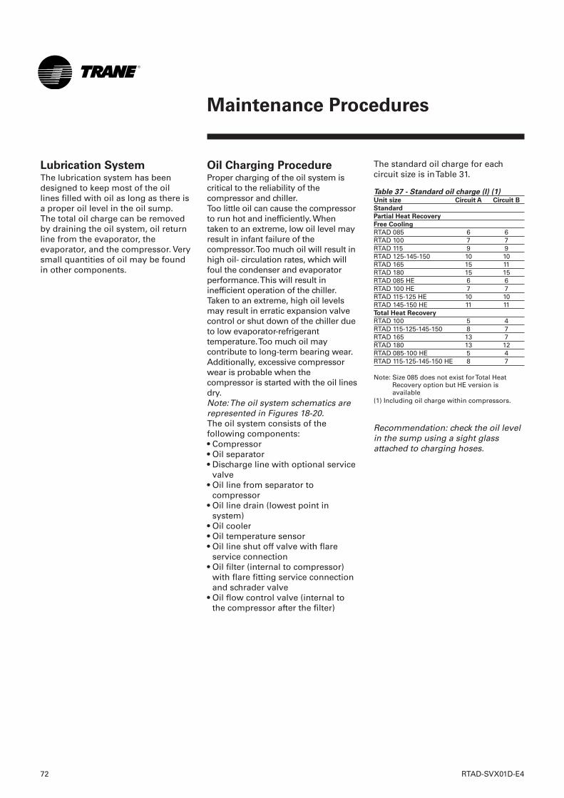
Oil Charging ProcedureProper charging of the oil system iscritical to the reliability of thecompressor and chiller.Too little oil can cause the compressorto run hot and inefficiently. Whentaken to an extreme, low oil level mayresult in infant failure of thecompressor. Too much oil will result inhigh oil- circulation rates, which willfoul the condenser and evaporatorperformance. This will result ininefficient operation of the chiller.Taken to an extreme, high oil levelsmay result in erratic expansion valvecontrol or shut down of the chiller dueto low evaporator-refrigeranttemperature. Too much oil maycontribute to long-term bearing wear.Additionally, excessive compressorwear is probable when thecompressor is started with the oil linesdry.Note: The oil system schematics arerepresented in Figures 18-20.The oil system consists of thefollowing components:• Compressor• Oil separator• Discharge line with optional service
valve• Oil line from separator to
compressor• Oil line drain (lowest point in
system)• Oil cooler• Oil temperature sensor• Oil line shut off valve with flare
service connection• Oil filter (internal to compressor)
with flare fitting service connectionand schrader valve
• Oil flow control valve (internal tothe compressor after the filter)
The standard oil charge for eachcircuit size is in Table 31.
Table 37 - Standard oil charge (l) (1)Unit size Circuit A Circuit B
Standard
Partial Heat Recovery
Free Cooling
RTAD 085 6 6RTAD 100 7 7RTAD 115 9 9RTAD 125-145-150 10 10RTAD 165 15 11RTAD 180 15 15RTAD 085 HE 6 6RTAD 100 HE 7 7RTAD 115-125 HE 10 10RTAD 145-150 HE 11 11Total Heat Recovery
RTAD 100 5 4RTAD 115-125-145-150 8 7RTAD 165 13 7RTAD 180 13 12RTAD 085-100 HE 5 4RTAD 115-125-145-150 HE 8 7
Note: Size 085 does not exist for Total HeatRecovery option but HE version isavailable
(1) Including oil charge within compressors.
Recommendation: check the oil levelin the sump using a sight glassattached to charging hoses.
Lubrication SystemThe lubrication system has beendesigned to keep most of the oillines filled with oil as long as there isa proper oil level in the oil sump.The total oil charge can be removedby draining the oil system, oil returnline from the evaporator, theevaporator, and the compressor. Verysmall quantities of oil may be foundin other components.
72 RTAD-SVX01D-E4
Maintenance Procedures
RTAD-SVX01D-E4 73
Maintenance Procedures
1 To measure the oil level, use the oildrain valve on the oil line and aservice valve on the discharge line.This measurement can only bemade when the circuit is notrunning. Note: the bottom plate of the oilseparator is approximately 25mm(1'') thick.
2 After the unit has run for a while,the oil level in the sump can varygreatly. However, if the unit hasrun "normal" conditions for a longtime the level should be between25 to -100mm (+1" to - 4" )
The field charging proceduredepends on the circumstances thatresulted in the need for oilcharge.1 Some service procedures may
result in loss of small quantities ofoil that must be replaced (oilanalysis, compressor filterreplacement, re-tubing theevaporator, and so forth.).
2 Additionally, some maintenanceprocedures may result in virtuallyall of the oil being removed(compressor motor burn or totalremoval of the charge to troubleshoot a unit).
3 Finally, leaks may result in a loss ofoil that must be replaced.
Factory (initial) Oil-
Charging ProcedureThe initial charging procedureshould be followed any time the unitis new or has had all of the oilremoved.1 Add 1 liter oil to the motor cavity
or suction line prior to installingthe compressor into the chiller.
2 The oil-line shutoff valve must beopen to allow the oil to pass intothe oil lines and the oil separator.
3 The oil charging port is a ¼" (6mm)flare fitting with a schrader valvethat is on the side of the oil-filterhousing. This is the port that mustbe used to add oil into thecompressor so that the filter andlines are full at the first start of thecompressor.
4 Oil may be put into the unit usingeither of two methods:
CAUTION! Use only Trane Oil 00048
in the RTAD units to avoid any
catastrophic damage to the
compressor or unit.
• Have the unit in vacuum. Hook upthe oil charging hose to oil chargingfitting and submerse the other endinto the oil container. Let thevacuum draw the required amountof oil into the unit.
• Have the unit at the same pressureas the oil. Hook up the oil charginghose to the oil charging fitting andthe other end to an oil pump. Usethe pump to draw oil out of the oilcontainer and push the requiredamount of oil into the unit.
Note: the compressor filter has aninternal shut off valve that willprevent oil from entering thecompressor while the compressor isnot running. Therefore, there is noconcern about flooding thecompressor with oil.
Note: Ensure that the compressor isnot pressurized.3 Open the flare fitting on the oil-line
shut off valve.4 Open the flare fitting on the filter
housing. This is the port that mustbe used to put oil into thecompressor.
5 Install charging hose on oilcharging port (with the Schradervalve) and the other on the oilcanister.
6 Lift the oil canister, or use a pump,to pour oil into the filter housing.
7 When oil comes out of the flarefitting on the oil line shut off valvethe filter is full. Stop adding oil.
8 Put the cap on the flare on the oilline shut off valve, remove thecharging hose and put the cap backon the flare on the filter housing.
9 Vacuum the compressor (low side)and prepare it for inclusion in thesystem. There is a service valve onthe suction line. Use these valvesto vacuum the compressor.
10 Open the oil line shut off valve.Severe damage to the compressorcan result if the oil line shut offvalve is closed when thecompressor is started.
WARNING! Catastrophic damage to
the compressor will occur if the oil
line shut off valve or the isolation
valves are left closed on unit start-
up.
11 Open the other compressorisolation valves.
Note: this procedure assumes thatthe oil that is put into the filterhousing does not have contaminantssuch as non-condensable gases. Theoil forces these gases out of the filterand oil line shut off valve without theneed to pull a vacuum on this smallvolume. If the oil has been in anopen container or is otherwisecontaminated, then this smallvolume must be subject to vacuumas well. However, the filter cavity isfull of oil. Therefore, be sure to use aflash tank in line with the vacuumpump to make sure that oil, that ispulled out of the filter cavity, doesnot slug the vacuum pump.
Field Oil-Charging
ProcedureUse the initial charging procedurewhen virtually all of the oil has beenremoved.Note: this procedure can be followedeven with the refrigerant chargeisolated in the evaporating section ofthe unit.
If small quantities of oil were
removed to service refrigeration
components, such as theevaporator, simply replace the oilthat was removed into the servicedcomponent prior to vacuum andrecharge of the refrigerant.
If oil was removed to service a
compressor or change the filter
follow this procedure:1 If the compressor is a new
compressor or has been removedfrom the system and reworked,add 1 liter oil to the motor cavityprior to installing the compressorinto the chiller.
2 Install the compressor in thesystem. Make sure that the filtershut off valve is closed.
Other compressor isolation valvesmay also be closed depending uponthe service that was completed. Forexample, changing the oil filterwould require the compressor to beisolated and pulled into vacuum.
74 RTAD-SVX01D-E4
Maintenance Procedures
RTAD-SVX01D-E4 75
Maintenance Procedures
Evaporator Heat Tape
Checkout ProcedureCAUTION! If the heat tapes wrapped
around the evaporator barrel fail, the
evaporator will freeze causing
catastrophic damage to the entire
unit.
To check the heat tapes wrappedaround the barrel follow theprocedures below.1 Locate the connection under the
evaporator insulation near thebottom of the barrel.
CAUTION! Do not cut past the
evaporator insulation. Electrical
damage to the heat tape wires will
occur if cutting of the insulation is
done improperly.
The resistance can be checked withan ohmmeter to determine if there isan open or a short. If a heater hasfailed, replace as follows:1 Remove the insulation around the
heater.2 Remove the old heater.3 The factory installed heaters have
the wire run under the insulation ofthe evaporator. This can be copiedby cutting a small strip ofinsulation out and replacing it withtape.
4 Replace any insulation that wasremoved.
5 Wire the heaters into the system asper the wiring diagram.
6 Recheck the resistance to verifythat they are wired correctly.
Safety recommendationsTo avoid accidents and damage, thefollowing recommendations shouldbe observed during maintenanceand service visits:1. The maximum allowable pressures
for system leak testing on low andhigh pressure side are given in thechapter "Installation". Alwaysprovide a pressure regulator.
2. Disconnect the main supply beforeany servicing on the unit.
3. Service work on the refrigerationsystem and the electrical systemshould be carried out only byqualified and experiencedpersonnel.
American Standard Europe BVBARegistered Office: 1789 Chaussée de Wavre, 1160 Brussels - Belgium
www.trane.com
For more information, contact your local sales office or e-mail us at [email protected]
Trane has a policy of continuous product and product data improvement and reserves the right to changedesign and specifications without notice. Only qualified technicians should perform the installation andservicing of equipment referred to in this publication.
Literature Order Number RTAD-SVX01D-E4
Date 0106
Supersedes RTAD-SVX01C-E4_0705
Stocking Location Europe