Embed Size (px)
Citation preview
Original Instructions
Installation, Operation & Maintenance ManualSentry ISOLOK SAL-DBB SamplerPoint Samplers
S-LS-IOM-00303-8 9-16
2 Sentry Equipment Corp
Do not install, maintain, or operate this equipment without reading, understanding, and following the appropriate Sentry Equipment Corp instructions . Otherwise, injury, damage, or both may result .
Copyright© 2016 by Sentry Equipment Corp . All rights reserved . All product and company names are property of their respective owners . This document contains proprietary information . No part of this document may be photocopied or reproduced without the prior written consent of Sentry Equipment Corp .
Limit of LiabilitySentry Equipment Corp, its employees, agents, and the authors and contributors to this document specifi cally disclaim all liabilities and warranties, express or implied (including warranties of merchantability and fi tness for a particular purpose), for the accuracy, currency, completeness, and/or reliability of the information contained herein and/or for the fi tness for any particular use and/or for the performance of any material and/or equipment selected in whole or part with the user of/or in reliance upon information contained herein . Selection of materials and/or equipment is at the sole risk of the user of this publication .
NoteThe information contained in this document is subject to change without notice .
Sentry ISOLOK SAL-DBB Sampler 3
Table of Contents
Safety Information . . . . . . . . . . . . . . . . . . . . . . . . . . . . . . . . . . . . . . . . .4
General Safety Precautions . . . . . . . . . . . . . . . . . . . . . . . . . . . . . . . . .5
General Description . . . . . . . . . . . . . . . . . . . . . . . . . . . . . . . . . . . . . . . .6
Installation . . . . . . . . . . . . . . . . . . . . . . . . . . . . . . . . . . . . . . . . . . . . . . . . .7Receiving . . . . . . . . . . . . . . . . . . . . . . . . . . . . . . . . . . . . . . . . . . . . . . . . . . . . . . . . . . . .7
Selection of mounting location . . . . . . . . . . . . . . . . . . . . . . . . . . . . . . . . . . . . . .7
Line Adapter Mounting (if provided) . . . . . . . . . . . . . . . . . . . . . . . . . . . . . . . . .8
Valve Mounting . . . . . . . . . . . . . . . . . . . . . . . . . . . . . . . . . . . . . . . . . . . . . . . . . . . . . .8
Sampler Mounting . . . . . . . . . . . . . . . . . . . . . . . . . . . . . . . . . . . . . . . . . . . . . . . . . . .8
Controller Mounting (if provided) . . . . . . . . . . . . . . . . . . . . . . . . . . . . . . . . . . . .9
Operation . . . . . . . . . . . . . . . . . . . . . . . . . . . . . . . . . . . . . . . . . . . . . . . . . .9Set Cycle Rate . . . . . . . . . . . . . . . . . . . . . . . . . . . . . . . . . . . . . . . . . . . . . . . . . . . . . . .9
Insert Sampler . . . . . . . . . . . . . . . . . . . . . . . . . . . . . . . . . . . . . . . . . . . . . . . . . . . . . . .9
Remove Sampler . . . . . . . . . . . . . . . . . . . . . . . . . . . . . . . . . . . . . . . . . . . . . . . . . . . .10
Maintenance . . . . . . . . . . . . . . . . . . . . . . . . . . . . . . . . . . . . . . . . . . . . . . .10Plunger Seal Replacement . . . . . . . . . . . . . . . . . . . . . . . . . . . . . . . . . . . . . . . . . . .10
Sampler Seal Replacement . . . . . . . . . . . . . . . . . . . . . . . . . . . . . . . . . . . . . . . . . . .11
Valve Stem Packing Adjustment . . . . . . . . . . . . . . . . . . . . . . . . . . . . . . . . . . . . . .11
Freeing a Stuck Sampler . . . . . . . . . . . . . . . . . . . . . . . . . . . . . . . . . . . . . . . . . . . . .12
Cleaning . . . . . . . . . . . . . . . . . . . . . . . . . . . . . . . . . . . . . . . . . . . . . . . . . . . . . . . . . . . .12
Pipeline Maintenance (if required) . . . . . . . . . . . . . . . . . . . . . . . . . . . . . . . . . . . .12
Recommended Spare Parts . . . . . . . . . . . . . . . . . . . . . . . . . . . . . . . . .13Actuator Parts . . . . . . . . . . . . . . . . . . . . . . . . . . . . . . . . . . . . . . . . . . . . . . . . . . . . . . .13
Double Block and Bleed Valve Parts . . . . . . . . . . . . . . . . . . . . . . . . . . . . . . . . . .14
DBB Tools . . . . . . . . . . . . . . . . . . . . . . . . . . . . . . . . . . . . . . . . . . . . . . . . . . . . . . . . . . .14
Standard Warranty . . . . . . . . . . . . . . . . . . . . . . . . . . . . . . . . . . . . . . . . .14
Customer Support . . . . . . . . . . . . . . . . . . . . . . . . . . . . . . . . . . . . . . . . . .15
4 Sentry Equipment Corp
Safety InformationPlease read the entire manual before attempting to unpack, set up, or operate this product . Pay careful attention to all Warnings, Cautions, and Notes . Failure to do so could result in serious personal injury and/or equipment damage .
Use of Hazard Information
If multiple hazards exist, the signal word corresponding to the greatest hazard shall be used .
Defi nitions
DANGER indicates a hazardous situation which, if not avoided, will result in death or serious injury .
WARNING indicates a hazardous situation which, if not avoided, could result in death or serious injury .
CAUTION, used with the safety alert symbol, indicates a hazardous situation which, if not avoided, could result in minor or moderate injury .
NOTICE is used to address practices not related to personal injury .
 NOTEInformation that requires special emphasis .
 TIPAlternate techniques or clarifying information.
SHALL: This word is understood to be mandatory .
SHOULD: This word is understood to be advisory .
Sentry ISOLOK SAL-DBB Sampler 5
General Safety PrecautionsProduct Selection, Installation, and Use
Improper selection, installation, or use can cause personal injury or property damage . It is solely the responsibility of users, through their own analysis and testing, to select products suitable for their specifi c application requirements, ensure they are properly maintained, and limit their use to their intended purpose .
Follow proper local, state, and federal regulations for proper installation and operational requirements .
Always use caution and common sense when working with any chemical . Read the product label and Material Safety Data Sheets (MSDS) carefully and follow the instructions exactly .
Potential Equipment Hazards
Hot surfaces! This equipment may have very hot surfaces . If an operator contacts a hot surface, injury may occur . Use protective clothing to prevent injury . If other equipment comes in contact with a hot surface, damage to the equipment may occur . Ensure the area around this equipment is kept clear to prevent damage from occurring .
High pressures! This equipment may contain fl uids at very high pressures . Prior to installing, removing or maintaining this equipment, ensure that the equipment is isolated from all connecting piping, the equipment is depressurized, the contents have been drained, and the equipment is cool .
Moving parts! This equipment may contain moving parts . All drive guards and doors must be secured in place when this machine is being operated .
Equipment rated TX . Equipment maximum surface temperature depends on operating conditions . Ensure maximum surface temperature shall stay below ignition temperature of dust or gas atmosphere where it is installed based on process conditions . Failure to comply could result in an explosion, causing serious injury or death to personnel and damage to equipment .
If the sampler is mounted directly to a non-electrically conductive surface, sampler shall be bonded to a grounding electrode . Failure to comply could result in sparking, which could lead to an explosion, causing harm to personnel and equipment .
If the sample container is removed from the sampler, do not insert any body part or other item into the sample discharge port . Crushing will occur .
To ensure proper sampler operation, be sure the sampler is installed in a pipe large enough for the sampler plunger to extend without impacting the pipe . Failure to comply will result in equipment damage and poor sample quality .
6 Sentry Equipment Corp
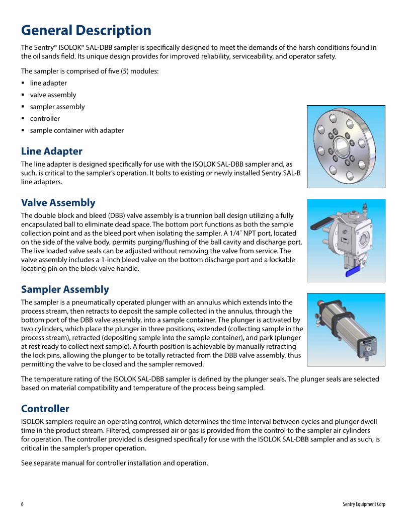
General DescriptionThe Sentry® ISOLOK® SAL-DBB sampler is specifically designed to meet the demands of the harsh conditions found in the oil sands field . Its unique design provides for improved reliability, serviceability, and operator safety .
The sampler is comprised of five (5) modules:
� line adapter
� valve assembly
� sampler assembly
� controller
� sample container with adapter
Line AdapterThe line adapter is designed specifically for use with the ISOLOK SAL-DBB sampler and, as such, is critical to the sampler’s operation . It bolts to existing or newly installed Sentry SAL-B line adapters .
Valve AssemblyThe double block and bleed (DBB) valve assembly is a trunnion ball design utilizing a fully encapsulated ball to eliminate dead space . The bottom port functions as both the sample collection point and as the bleed port when isolating the sampler . A 1/4˝ NPT port, located on the side of the valve body, permits purging/flushing of the ball cavity and discharge port . The live loaded valve seals can be adjusted without removing the valve from service . The valve assembly includes a 1-inch bleed valve on the bottom discharge port and a lockable locating pin on the block valve handle .
Sampler AssemblyThe sampler is a pneumatically operated plunger with an annulus which extends into the process stream, then retracts to deposit the sample collected in the annulus, through the bottom port of the DBB valve assembly, into a sample container . The plunger is activated by two cylinders, which place the plunger in three positions, extended (collecting sample in the process stream), retracted (depositing sample into the sample container), and park (plunger at rest ready to collect next sample) . A fourth position is achievable by manually retracting the lock pins, allowing the plunger to be totally retracted from the DBB valve assembly, thus permitting the valve to be closed and the sampler removed .
The temperature rating of the ISOLOK SAL-DBB sampler is defined by the plunger seals . The plunger seals are selected based on material compatibility and temperature of the process being sampled .
ControllerISOLOK samplers require an operating control, which determines the time interval between cycles and plunger dwell time in the product stream . Filtered, compressed air or gas is provided from the control to the sampler air cylinders for operation . The controller provided is designed specifically for use with the ISOLOK SAL-DBB sampler and as such, is critical in the sampler’s proper operation .
See separate manual for controller installation and operation .
Sentry ISOLOK SAL-DBB Sampler 7
Sample Container with Adapter
Dangerous gas! The gases being emitted from the bottle vent may be hazardous and toxic upon exposure . The vent line should be directed to a charcoal canister, flare, or other sub atmospheric region for collection and treatment of sample vapors .
Always ensure control is OFF before mounting or exchanging sample containers .
Sample collection containers should always be clean and completely dry before being used . Polypropylene containers (bottles) are common .
Screw Mount Containers
Standard sampler body is provided with a 1-inch tri-clamp discharge port . Adapters to fit threaded sample collection bottles are available from Sentry Equipment . These adapters have a suitable connection and mount onto the discharge port .
Separate Containers
Suitable piping connections for metal or plastic components can be arranged to conduct sample portions to a separate container . Whenever such piping is installed, avoid long runs with multiple fittings, joints, or other areas where solids or crystals could build up and block flow .
 NOTESelect a sample container size that will not be completely filled, even on longest sampling times . Use care when setting a cycle rate that may nearly fill a container .
Installation
Receiving � Examine the crate and all contents for any shipping damage immediately after receipt .
� Take pictures of any suspected damage .
� Report damages to the delivery company at once . This is the responsibility of the consignee .
Selection of mounting location � Select a location where the material in the process stream is well mixed .
� Ensure the sample collection container will clear vertical lines (or other obstructions) when mounted onto the sampler .
8 Sentry Equipment Corp
Line Adapter Mounting (if provided)
Use industry code procedures to protect the line adapter from distortion . Major distortion cannot be corrected and will prevent installation of sampler .
Determine which type of line adapter has been provided:
� Bolt-on line adapters are designed to bolt onto existing Sentry SAL-B line adapters .
� Weld-on line adapters are designed for new installations through the wall of larger diameter pipes or sides of tanks .
For new installations:
1. Select a location and verify sampler orientation .
2. Cut a hole in the process line (or tank) according to the shape of the line adapter . Exact size to cut is shown on the accompanying drawings
3. Protect the bore and face of the adapter from weld spatter .
4. Tack weld adapter in position .
5. Verify orientation and position before continuing to weld .
Valve Mounting1. Verify that the bore of the line adapter is free of burrs, scratches, or foreign material .
2. Lubricate the O-ring on the front sleeve of the valve assembly with a process compatible lubricant .
3. Slide valve assembly into place with the bleed valve facing down and fasten with supplied fasteners .
4. Torque mounting nuts to 75 ft-lb (101 .7 Nm) .
5. If the flushing feature is going to be used, connect the flush source to the port on the side of the valve body . The flush line should employ a check valve at the valve body . If this feature is not being used, plug this port .
6. Verify that the block valve is closed and the bleed valve is open before introducing product into the pipeline/vessel .
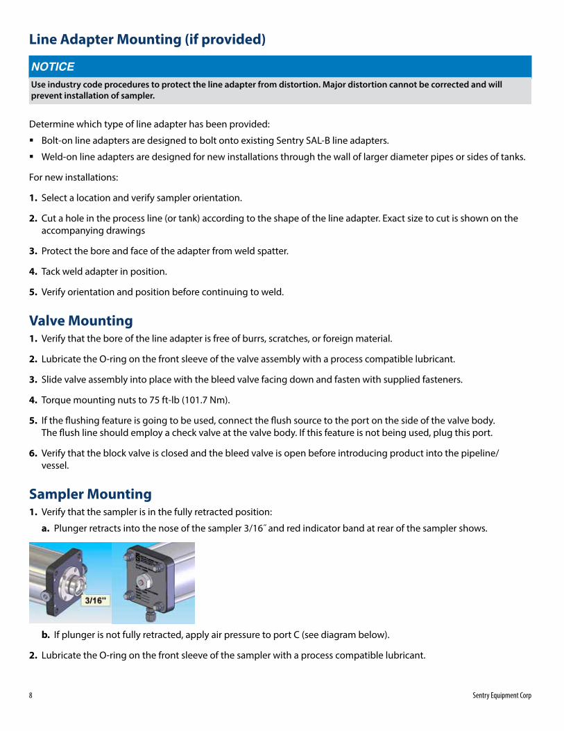
Sampler Mounting1. Verify that the sampler is in the fully retracted position:
a. Plunger retracts into the nose of the sampler 3/16˝ and red indicator band at rear of the sampler shows .
b. If plunger is not fully retracted, apply air pressure to port C (see diagram below) .
2. Lubricate the O-ring on the front sleeve of the sampler with a process compatible lubricant .
Sentry ISOLOK SAL-DBB Sampler 9
3. Insert the nose of the sampler into the valve bore and push into place .
4. Install four (4) 7/16 –14 x 1˝ socket head cap screws and tighten evenly using a 3/8˝ hex wrench . Note: A ball tip style wrench works best in this application .
Controller Mounting (if provided)
Failure to connect the pneumatic tubing correctly can cause damage to the sampler and/or the valve assembly .
1. Locate the controller as close as possible to the sampler . Keep pneumatic line lengths to 20 ft (6 .1 m) or less .
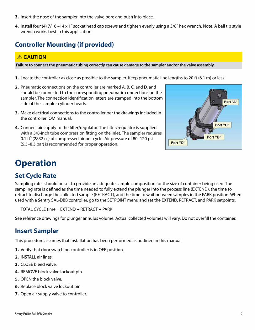
2. Pneumatic connections on the controller are marked A, B, C, and D, and should be connected to the corresponding pneumatic connections on the sampler . The connection identification letters are stamped into the bottom side of the sampler cylinder heads .
3. Make electrical connections to the controller per the drawings included in the controller IOM manual .
4. Connect air supply to the filter/regulator . The filter/regulator is supplied with a 3/8-inch tube compression fitting on the inlet . The sampler requires 0 .1 ft3 (2832 cc) of compressed air per cycle . Air pressure of 80–120 psi (5 .5–8 .3 bar) is recommended for proper operation .
OperationSet Cycle Rate Sampling rates should be set to provide an adequate sample composition for the size of container being used . The sampling rate is defined as the time needed to fully extend the plunger into the process line (EXTEND), the time to retract to discharge the collected sample (RETRACT), and the time to wait between samples in the PARK position . When used with a Sentry SAL-DBB controller, go to the SETPOINT menu and set the EXTEND, RETRACT, and PARK setpoints .
TOTAL CYCLE time = EXTEND + RETRACT + PARK
See reference drawings for plunger annulus volume . Actual collected volumes will vary . Do not overfill the container .
Insert SamplerThis procedure assumes that installation has been performed as outlined in this manual .
1. Verify that door switch on controller is in OFF position .
2. INSTALL air lines .
3. CLOSE bleed valve .
4. REMOVE block valve lockout pin .
5. OPEN the block valve .
6. Replace block valve lockout pin .
7. Open air supply valve to controller .
10 Sentry Equipment Corp
8. Verify poppet is in . The red band on the position indicator should be hidden .
9. Insert actuator lock pins .
10. OPEN the bleed valve .
11. Installation is complete . The sampler is in PARK position .
Remove Sampler1. Place door switch on controller in OFF position .
2. CLOSE the bleed valve
3. Verify that the spacer is extended . The red band on the position indicator should be hidden .
4. Retract lock pins .
5. Verify that the spacer is retracted . The red band on the position indicator should be visible .
6. Remove block valve lockout pin .
7. CLOSE the block valve .
8. Replace block valve lockout pin .
9. OPEN bleed valve . (Note: A momentary pressure relief may occur when the bleed valve is opened .)
10. Close air supply valve to the controller .
11. Remove sampler .
12. Install block-off plate .
13. Removal is complete .
MaintenancePlunger Seal Replacement
Decompression of seals may occur as plunger is removed . Protect personnel from exposure to sample material trapped between plunger seals .
 NOTE:When disassembling the plunger assembly, note the proper orientation of the assembly components .
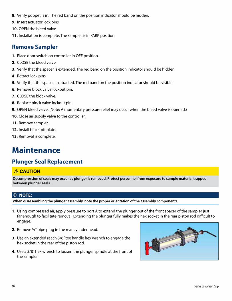
1. Using compressed air, apply pressure to port A to extend the plunger out of the front spacer of the sampler just far enough to facilitate removal . Extending the plunger fully makes the hex socket in the rear piston rod difficult to engage .
2. Remove ½˝ pipe plug in the rear cylinder head .
3. Use an extended reach 3/8˝ tee handle hex wrench to engage the hex socket in the rear of the piston rod .
4. Use a 3/8˝ hex wrench to loosen the plunger spindle at the front of the sampler .
Sentry ISOLOK SAL-DBB Sampler 11
DO NOT nick or scratch seal seats
5. If any seal is worn flat on the outside diameter, torn, scored or experiencing chemical degradation, remove seals from carriers and sleeve .
6. Check to ensure spindle is not bent and all parts are smooth and free of score marks . Scored or damaged parts should be repaired or replaced .
7. Reassemble the components of the plunger assembly in reverse order of disassembly . If you are unsure of component orientation, reference the attached drawings .
8. Reinstall plunger assembly onto piston rod and tighten with wrenches .
9. Replace the pipe plug in the rear cylinder head .
10. Apply air pressure to port B to return the sampler to the fully retracted position before reinstalling .
Sampler Seal Replacement1. Remove plunger assembly as described above .
2. Remove the four (4) nuts and washers retaining the rear cylinder head .
3. Remove rear cylinder head and rear cylinder tube .
4. Remove rear piston and rod assembly .
5. Remove four (4) tie rods from center cylinder head .
6. Remove four (4) bolts holding front cylinder together .
7. Remove center cylinder head .
8. Remove front cylinder tube and piston .
9. Remove and replace all cylinder head to cylinder tube O-rings .
10. Remove and replace two (2) rear piston seals .
11. Remove and replace two (2) front piston OD seals and two (2) front piston ID seals .
12. Remove and replace center cylinder head ID seal .
13. Remove and replace inner spacer, rear inner seal .
14. Remove and replace rear sleeve outer seal (front nose of sampler) .
15. Inspect bore of cylinder for scoring or wear . Wipe out with a dry, non-abrasive cloth .
16. Wipe seals with a light film of Dow Molykote® 33 Grease (or process compatible equivalent) as aid in assembly .
17. Reassemble sampler in reverse order of disassembly .
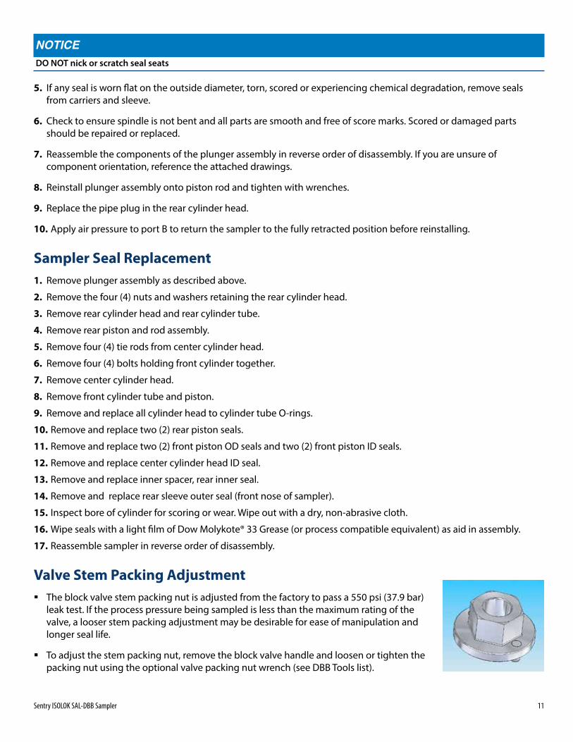
Valve Stem Packing Adjustment � The block valve stem packing nut is adjusted from the factory to pass a 550 psi (37 .9 bar)
leak test . If the process pressure being sampled is less than the maximum rating of the valve, a looser stem packing adjustment may be desirable for ease of manipulation and longer seal life .
� To adjust the stem packing nut, remove the block valve handle and loosen or tighten the packing nut using the optional valve packing nut wrench (see DBB Tools list) .
12 Sentry Equipment Corp
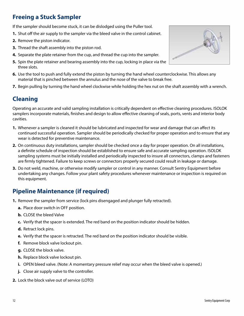
Freeing a Stuck SamplerIf the sampler should become stuck, it can be dislodged using the Puller tool .
1. Shut off the air supply to the sampler via the bleed valve in the control cabinet .
2. Remove the piston indicator .
3. Thread the shaft assembly into the piston rod .
4. Separate the plate retainer from the cup, and thread the cup into the sampler .
5. Spin the plate retainer and bearing assembly into the cup, locking in place via the three slots .
6. Use the tool to push and fully extend the piston by turning the hand wheel counterclockwise . This allows any material that is pinched between the annulus and the nose of the valve to break free .
7. Begin pulling by turning the hand wheel clockwise while holding the hex nut on the shaft assembly with a wrench .
CleaningOperating an accurate and valid sampling installation is critically dependent on effective cleaning procedures . ISOLOK samplers incorporate materials, finishes and design to allow effective cleaning of seals, ports, vents and interior body cavities .
1. Whenever a sampler is cleaned it should be lubricated and inspected for wear and damage that can affect its continued successful operation . Sampler should be periodically checked for proper operation and to ensure that any wear is detected for preventive maintenance .
2. On continuous duty installations, sampler should be checked once a day for proper operation . On all installations, a definite schedule of inspection should be established to ensure safe and accurate sampling operation . ISOLOK sampling systems must be initially installed and periodically inspected to insure all connectors, clamps and fasteners are firmly tightened . Failure to keep screws or connectors properly secured could result in leakage or damage .
3. Do not weld, machine, or otherwise modify sampler or control in any manner . Consult Sentry Equipment before undertaking any changes . Follow your plant safety procedures whenever maintenance or inspection is required on this equipment .
Pipeline Maintenance (if required)1. Remove the sampler from service (lock pins disengaged and plunger fully retracted) .
a. Place door switch in OFF position .
b. CLOSE the bleed Valve
c. Verify that the spacer is extended . The red band on the position indicator should be hidden .
d. Retract lock pins .
e. Verify that the spacer is retracted . The red band on the position indicator should be visible .
f. Remove block valve lockout pin .
g. CLOSE the block valve .
h. Replace block valve lockout pin .
i. OPEN bleed valve . (Note: A momentary pressure relief may occur when the bleed valve is opened .)
j. Close air supply valve to the controller .
2. Lock the block valve out of service (LOTO)
Sentry ISOLOK SAL-DBB Sampler 13
3. Remove power from the controller by pressing the E-Stop
4. Once maintenance on the pipeline is complete, reenergize power on the controller by pulling the E-Stop .
5. Remove the LOTO from the block valve
6. Return the sampler to service .
a. Verify that door switch on the controller is in OFF position .
b. INSTALL air lines .
c. CLOSE Bleed Valve .
d. REMOVE Block Valve lockout pin .
e. OPEN the Block Valve .
f. Replace Block Valve lockout pin .
g. Open air supply valve to controller .
h. Verify poppet is in . The red band on the position indicator should be hidden .
i. Insert actuator Lock Pins .
j. OPEN the Bleed Valve .
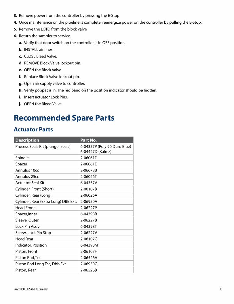
Recommended Spare PartsActuator Parts
Description Part No.Process Seals Kit (plunger seals) 6-04357P (Poly 90 Duro Blue)
6-04427D (Kalrez)Spindle 2-06061FSpacer 2-06061EAnnulus 10cc 2-06678BAnnulus 25cc 2-06026TActuator Seal Kit 6-04357VCylinder, Front (Short) 2-06107BCylinder, Rear (Long) 2-06026ACylinder, Rear (Extra Long) DBB Ext . 2-06950AHead Front 2-06227PSpacer,Inner 6-04398RSleeve, Outer 2-06227BLock Pin Ass'y 6-04398TScrew, Lock Pin Stop 2-06227VHead Rear 2-06107CIndicator, Position 6-04398MPiston, Front 2-06107HPiston Rod,Tcc 2-06526APiston Rod Long,Tcc, Dbb Ext . 2-06950CPiston, Rear 2-06526B
14 Sentry Equipment Corp
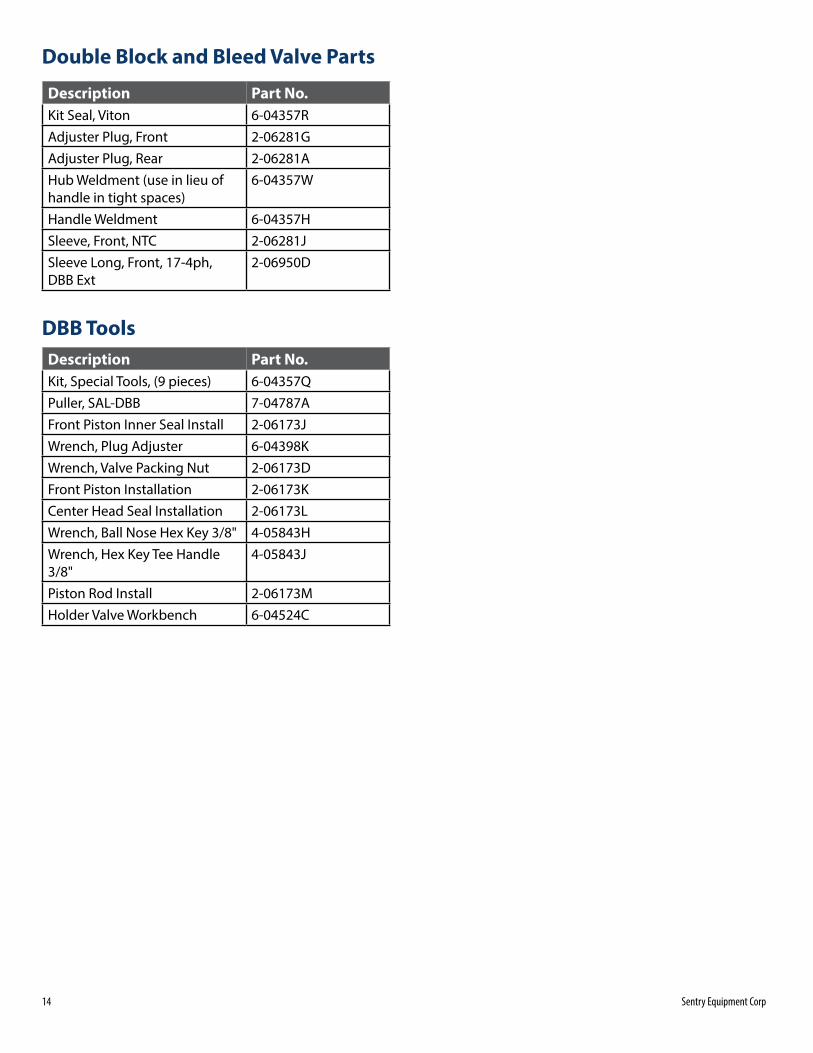
Double Block and Bleed Valve Parts
Description Part No.Kit Seal, Viton 6-04357RAdjuster Plug, Front 2-06281GAdjuster Plug, Rear 2-06281AHub Weldment (use in lieu of handle in tight spaces)
6-04357W
Handle Weldment 6-04357HSleeve, Front, NTC 2-06281JSleeve Long, Front, 17-4ph, DBB Ext
2-06950D
DBB ToolsDescription Part No.Kit, Special Tools, (9 pieces) 6-04357QPuller, SAL-DBB 7-04787AFront Piston Inner Seal Install 2-06173JWrench, Plug Adjuster 6-04398KWrench, Valve Packing Nut 2-06173DFront Piston Installation 2-06173KCenter Head Seal Installation 2-06173LWrench, Ball Nose Hex Key 3/8" 4-05843HWrench, Hex Key Tee Handle 3/8"
4-05843J
Piston Rod Install 2-06173MHolder Valve Workbench 6-04524C
Sentry ISOLOK SAL-DBB Sampler 15
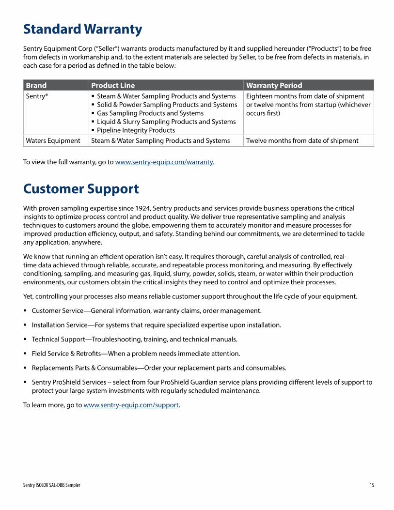
Standard WarrantySentry Equipment Corp (“Seller”) warrants products manufactured by it and supplied hereunder (“Products”) to be free from defects in workmanship and, to the extent materials are selected by Seller, to be free from defects in materials, in each case for a period as defi ned in the table below:
Brand Product Line Warranty PeriodSentry® � Steam & Water Sampling Products and Systems
� Solid & Powder Sampling Products and Systems � Gas Sampling Products and Systems � Liquid & Slurry Sampling Products and Systems � Pipeline Integrity Products
Eighteen months from date of shipment or twelve months from startup (whichever occurs fi rst)
Waters Equipment Steam & Water Sampling Products and Systems Twelve months from date of shipment
To view the full warranty, go to www .sentry-equip .com/warranty .
Customer SupportWith proven sampling expertise since 1924, Sentry products and services provide business operations the critical insights to optimize process control and product quality . We deliver true representative sampling and analysis techniques to customers around the globe, empowering them to accurately monitor and measure processes for improved production effi ciency, output, and safety . Standing behind our commitments, we are determined to tackle any application, anywhere .
We know that running an effi cient operation isn’t easy . It requires thorough, careful analysis of controlled, real-time data achieved through reliable, accurate, and repeatable process monitoring, and measuring . By eff ectively conditioning, sampling, and measuring gas, liquid, slurry, powder, solids, steam, or water within their production environments, our customers obtain the critical insights they need to control and optimize their processes .
Yet, controlling your processes also means reliable customer support throughout the life cycle of your equipment .
� Customer Service—General information, warranty claims, order management .
� Installation Service—For systems that require specialized expertise upon installation .
� Technical Support—Troubleshooting, training, and technical manuals .
� Field Service & Retrofi ts—When a problem needs immediate attention .
� Replacements Parts & Consumables—Order your replacement parts and consumables .
� Sentry ProShield Services – select from four ProShield Guardian service plans providing diff erent levels of support to protect your large system investments with regularly scheduled maintenance .
To learn more, go to www .sentry-equip .com/support .
sentry-equip.com966 Blue Ribbon Circle North, Oconomowoc, WI 53066 U.S.A. | +1-262-567-7256 | [email protected]
Serving customers in more than 50 countries across six continents worldwide.