Embed Size (px)
Citation preview
Redi-Purge™ Microprocessor Controlled Ultra-High Efficiency “Gravity Flow” Non-Condensable Purge Unit For Use On
Centrifugal Chillers
Utilizing Refrigerants
R-11 & R-123
Manual for Models: 007-11-C3 and 007-123-C3
Virtual “Drop-in Replacement” for Trane’s Purifier® purger
Can also be used to replace Trane’s EarthWise™ purger * * When used with Redi Controls’ optional Emission Collection Carbon Canister…
REDI CONTROLS, INC.
Installation, Operation & Maintenance Manual
Literature File No. 1151-00
ETL Listed 3104248

2
Revised Technically as of July 13, 2012 © 2012 REDI CONTROLS, INC., GREENWOOD, INDIANA Trane Purifier® Purge, & EarthWise™, are trademarks of Trane™ in the United States and other countries.
3
TABLE OF CONTENTS GENERAL INFORMATION.………………….……….…………………...………….………………..………...5
Getting Started…………………….. ………………….……………..…………………………….……..….…..6 Solenoid Valve Elastomer Material Specifications Preliminary Unit Inspection………………………..………………….……………….………...…..…..…7 & 8 Removing Old Purifier® Purge Unit Mounting the 007 Redi-Purge Reconnecting purge lines Reconnecting Liquid Drain Back line… Reconnect pump-out compressor discharge vent line… Electrical Connections………………………….……………….……....…………….……….…….………8 & 9 Chiller RUN SIGNAL INITIAL START-UP SET CLOCK Select Operating Mode……………………………………………………………………………………..……..9 Verify Purge Tank Evaporator Temperature SYSTEM COMPONENTS………………………………………………….………………………….……10 & 11 FIGURES 1 & 2 Electrical Control Panel Purge Unit Control Panel Microprocessor Circuit Board Security-Lock Non-condensable Pump-out Circuit………………………………………………….……………………....11 Liquid Drain Back Filter Drier Optional Accessories Emission collection canister saturation alarm (0ption) Chiller mounted condenser temperature sensor TS-3 (option) FIGURE 3 Refrigeration System Components.…………………..……………….………...……….…..12 Components…………………………………………………………………………………………………12 &.13 Setting or Changing Operating Parameters……………………………….……..……………………….…14 Purger Fault setting……………………………………………………………………………....…..………….14 Fault BYPASS setting Dip Switch S1 settings……………………………………………………………………….……...….............15 Microprocessor Overview……………………………………………………………………………………….15 Safety Features Maximum Allowable Pump-out Time Exceeded (PURGE FAULT) Sensor Operation (SENSOR ERROR) Operating Modes………………………………………………………………………….……….…..………….16 MANUAL, AUTO, ADAPTIVE
FIGURE 4 KEYPAD DISPLAY…….………………….……………………………..…………………17 & 18 Keypad Switches SET CLOCK Keypad Switch
4
STOP Keypad Switch………………………………………………………….…………………………..……18 MANUAL Keypad Switch AUTO Keypad Switch ADAPTIVE Keypad Switch…………………………………………………………………………..…..19 & 20 SENSORS Keypad Switch SETTINGS Keypad Switch BYPASS Keypad Switch Recommended FAULT Bypass time………………………………………..……………………...…..20 & 21 Exiting Fault “BYPASS” Mode DIAG Keypad Switch PUMP Keypad Switch……………………………………………………………………………………..……21 COMPRESSOR Keypad Switch ALARM Keypad Switch AUX VALVE Keypad Switch LOGS Keypad Switch LOGS…………………………………………………………….……………………..………………..……21- 23 CLEAR LOGS Keypad Switch……………………………….……………………………….……….…23 & 24 RESET Keypad Switch STATUS Keypad Switch CURSOR Keypad Switches INFORMATION DISPLAYS………………………………………….………………………………………….24 STATUS Display LOG Display………………………………………………………………………………………….….…24 & 25 SENSORS Display……………………………………………………………………………………………….26 Pump-out Display TS-1 & TS-2 Sensor Error FAULT Indications: PURGE, DRAIN, BATTERY………………………………………...…………………27 MAINTENANCE…………………………………………………………..………………….……………………28 FIGURE 5 and 5A – Electrical…(Figure 5A is for Purge replacement on a York Chiller)…….……29 & 30 Troubleshooting………..…………………………………………………………………………..………31 & 32 Purge Refrigeration System Diagnostic Procedure………………………………………….………33 & 34 FIGURE 6 – Refrigeration Circuit Diagnostic Test Points Constant Pressure Expansion Valve CPVE……………………………………………….…..….……..…..34 Temperature Sensor TS-1…………………………………………………….….…….……….…...……34 & 35 Temperature Sensor TS-2 Optional Temperature Sensor TS-3 TABLE 1 – Sensor Temperature vs. Resistance Bypassing Pump-out Flow Restrictor……………………………………………………….….…….…35 & 36 WARRANTY………………………………………………………….………...……………………..…….……....37
5
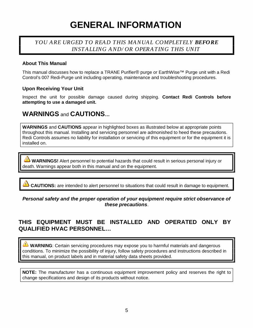
GENERAL INFORMATION
YOU ARE URGED TO READ THIS MANUAL COMPLETELY BEFORE INSTALLING AND/OR OPERATING THIS UNIT
About This Manual
This manual discusses how to replace a TRANE Purifier® purge or EarthWise™ Purge unit with a Redi Control’s 007 Redi-Purge unit including operating, maintenance and troubleshooting procedures. Upon Receiving Your Unit Inspect the unit for possible damage caused during shipping. Contact Redi Controls before attempting to use a damaged unit. WARNINGS and CAUTIONS… WARNINGS and CAUTIONS appear in highlighted boxes as illustrated below at appropriate points throughout this manual. Installing and servicing personnel are admonished to heed these precautions. Redi Controls assumes no liability for installation or servicing of this equipment or for the equipment it is installed on.
WARNINGS! Alert personnel to potential hazards that could result in serious personal injury or death. Warnings appear both in this manual and on the equipment.
CAUTIONS: are intended to alert personnel to situations that could result in damage to equipment. Personal safety and the proper operation of your equipment require strict observance of
these precautions.
THIS EQUIPMENT MUST BE INSTALLED AND OPERATED ONLY BY QUALIFIED HVAC PERSONNEL…
WARNING: Certain servicing procedures may expose you to harmful materials and dangerous conditions. To minimize the possibility of injury, follow safety procedures and instructions described in this manual, on product labels and in material safety data sheets provided.
NOTE: The manufacturer has a continuous equipment improvement policy and reserves the right to change specifications and design of its products without notice.
6
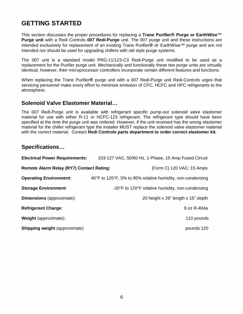
GETTING STARTED This section discusses the proper procedures for replacing a Trane Purifier® Purge or EarthWise™ Purge unit with a Redi Controls 007 Redi-Purge unit. The 007 purge unit and these instructions are intended exclusively for replacement of an existing Trane Purifier® or EarthWise™ purge and are not intended nor should be used for upgrading chillers with old style purge systems. The 007 unit is a standard model PRG-11/123-C3 Redi-Purge unit modified to be used as a replacement for the Purifier purge unit. Mechanically and functionally these two purge units are virtually identical, however, their microprocessor controllers incorporate certain different features and functions. When replacing the Trane Purifier® purge unit with a 007 Redi-Purge unit Redi-Controls urges that servicing personnel make every effort to minimize emission of CFC, HCFC and HFC refrigerants to the atmosphere.
Solenoid Valve Elastomer Material… The 007 Redi-Purge unit is available with refrigerant specific pump-out solenoid valve elastomer material for use with either R-11 or HCFC-123 refrigerant. The refrigerant type should have been specified at the time the purge unit was ordered. However, if the unit received has the wrong elastomer material for the chiller refrigerant type the installer MUST replace the solenoid valve elastomer material with the correct material. Contact Redi Controls parts department to order correct elastomer kit. Specifications… Electrical Power Requirements: 103-127 VAC, 50/60 Hz, 1-Phase, 15 Amp Fused Circuit Remote Alarm Relay (RY7) Contact Rating: (Form C) 120 VAC; 15 Amps Operating Environment: 40°F to 120°F, 5% to 95% relative humidity, non-condensing Storage Environment: -20°F to 120°F relative humidity, non-condensing Dimensions (approximate): 20 height x 26" length x 15" depth Refrigerant Charge: 9 oz R-404a Weight (approximate): 110 pounds Shipping weight (approximate) pounds 120
7
Preliminary Unit Inspection… Before installing the new 007 Redi-Purge unit, check data on unit nameplate and verify that the model number and voltage are correct for the application. It is also recommended that the purge unit’s sealed refrigeration system be bench tested prior to installation. This can be easily done by temporarily connecting unit to 120 VAC power Removing old Purifier® or EarthWise™ Purge unit…
WARNING! Be sure to open and lock-out all electrical disconnects to old purge system to prevent possible injury or death cause by electrical shock.
Before proceeding with unit replacement it is important that the installer thoroughly review and understand the following instructions. Although the 007 Redi-Purger is intended to be a drop-in replacement for the Purifier® and EarthWise™ Purge units some minor hook-up modifications may be required. Installation of the 007 Redi-Purge unit requires that the old Purifier® or EarthWise™ purge be disconnected and completely removed from the chiller, only leaving in place the mounting brackets and interconnecting gaseous pick-up and liquid return lines to chiller condenser. 1. Terminate chiller operation and disconnect all electrical power to the chiller and remove old purge unit.
2. Isolate purge system from chiller and recover refrigerant from old purge unit and filter-drier using proper refrigerant recovery equipment in accordance with recommended refrigerant recovery procedures.
WARNING! Handling refrigerants can be a serious health hazard and potentially cause death. NEVER drain liquid refrigerant into an open container or the atmosphere. Both liquid and gaseous refrigerant MUST be fully recovered utilizing proper refrigerant recovery equipment in accordance with recommended refrigerant recovery procedures. 3. Completely remove the old purge unit and filter/drier leaving only the existing refrigeration lines to
chiller condenser in place for reconnecting the 007 replacement unit.
Mounting the 007 Redi-Purge… Bolt the new 007 Redi-Purge base to the existing Purifier® / EarthWise™ purger mounting brackets. Some minor bolt-hole realignment or modification may be required.
Reconnecting purge lines… 1. Reconnect gaseous refrigerant pick-up line from chiller condenser to 5/8”gaseous refrigerant pick-up tube at top of 007 purge tank.
Reconnecting Liquid Drain Back line… 1. Using nuts and bolts provided mount liquid filter-drier onto front side of purge unit base. 2. Next, utilizing the provided 1/2” to 3/8” copper reducing coupling and preformed 3/8” inlet O-ring tube
assembly, connect the 1/2" drain tube exiting bottom of purge tank to the filter-drier inlet O-ring seal fitting (refer to FIG 3). Do not install O-ring at this time.
8
3. Silver solder or braze joints and allow to cool. 4. Install O-ring and tighten O-ring seal fitting nut. 5. Next, attach provided preformed 3/8” O-ring outlet tube assembly to the filter-drier outlet O-ring seal fitting as illustrated in FIG 3. Do not install O-ring at this time. 6. Silver solder or braze provided 3/8” isolation ball valve onto horizontal run of outlet tube assembly. Ball valve must be positioned a minimum of ½” higher than the filter-drier (refer to FIG 3). 7. Using the provided 3/8” to 1/4” copper reducing coupling reconnect existing ¼” liquid drain Line with existing moisture indicating sight glass to outlet of ball valve. Silver solder or braze joints and allow to cool. 8. Install O-ring and tighten O-ring seal fitting nut. 9. Properly evacuate complete purge system and leak test. Open isolation valves to chiller.
Reconnect pump-out compressor discharge vent line… Reconnect pump-out compressor non-condensable exhaust to external vent line in the same manor as was the old purge unit. Redi Controls recommends using 3/8-inch copper tubing to connect the purge pump-out compressor exhaust port to the chiller rupture disc vent line.
Electrical Connections… (Refer to Electrical Diagram Figure 5 page 29)
WARNING: Be sure to open and lock-out all electrical disconnects to prevent possible injury or death caused by electrical shock. The 007 unit requires three power connections. In most cases the existing Purifier® / EarthWise™ unit wiring can simply be reconnected to the appropriate power terminals in the 007 control panel. The electrical requirement is: 103-127 VAC, 50/60 Hz, 1-Phase 15 Amp Fused Circuit.
NOTE: Use Class 1, 14 AWG copper wire and metal conduit. All field installed wiring must comply with all applicable NEC and local electrical codes.
Chiller RUN SIGNAL… In most cases the same 120 VAC “RUN SIGNAL” source used by the Purifier® / EarthWise™ unit can be applied to the 007 unit. This RUN SIGNAL is typically from the hour meter or similar source that provides a 120 signal whenever the chiller is running.
NOTICE… if this unit is replacing a purge unit on a YORK chiller with either a “Micro-Panel” or “Optiview” control panel, you MUST wire the chiller “Run Signal” according to the Electrical Schematic Figure 5A on page 30.
INITIAL START-UP… 1. Re-open all valves to purge unit. 2. Apply power to purge unit. The LCD should display: System Ready Select Mode
Alternating with: System Ready
time: 00:00 AM
NOTE: Upon initial power-up the purge display may read BATTERY FAULT PRESS RESET KEY. Simply press the RESET Keypad Switch to reset and the display should then read as in step 2 above.
9
SET CLOCK Press “SET CLOCK” Keypad Switch, display changes to: Set CLK 00:00 AM The display reads “00:00” (hours : minutes). The underline is the cursor. To set the clock use the cursor movement < > keypad switches to move the cursor beneath the position you wish to change. To change the setting use the numbered keypad switches. To change between AM and PM move cursor beneath A or P and press any numbered keypad switch. Once the correct time has been set, you must press the ENTER keypad switch to enter new setting. Display changes to: System ready
Select Mode Alternating with: System Ready Example: 7:13 AM (time just set) Select Operating Mode The purge unit has three (3) selective operating modes. To select desired mode press one of the following keypad switches (MANUAL, AUTO, or ADAPTIVE). MANUAL mode purge operation is continuous whether chiller is ON or OFF. This mode is recommended for use ONLY during servicing or testing procedures. AUTO mode purge operation interlocks with a chiller-generated RUN signal which provides a 120 volt signal to the purge unit’s microprocessor controller. AUTO and ADAPTIVE mode operation is identical except that in AUTO mode purge operation is active only while the chiller is running. In ADAPTIVE mode, the purge system operates in a “self-learning” and “self-adjusting” duty cycle mode based upon previous non-condensable pump-out history. In this mode purge operation is independent of chiller operating status, and will Duty Cycle (start and stop purging activity as needed) whether the chiller is running or not. Security-Lock The 007 unit is equipped with a security lock system that prevents unauthorized personnel from tampering with certain functions. The purge unit comes from the factory with the security lock enabled (see Dip switch S1 settings starting on page 15). Verify Purge Tank Evaporator Temperature…
It is imperative that the purge tank evaporator temperature be set properly Press SENSORS Display Keypad Switch to view EVAPORATOR temperature.
EVAPORATOR °F (Proper setting 0º to +5º) If evaporator temperature is not within 0°F to 5°F range it will be necessary to re-calibrate the constant pressure expansion valve (CPEV). This is done by removing the plastic cap on top of the CPEV and turning the adjustment nut. Turn nut CW to increase temperature and CCW to decrease temperature. Turn ¼ turn and wait one minute to give the system time to adjust to new setting. Repeat process until evaporator temperature is within specified range.
10
SYSTEM IS NOW OPERATIONAL
SYSTEM COMPONENTS
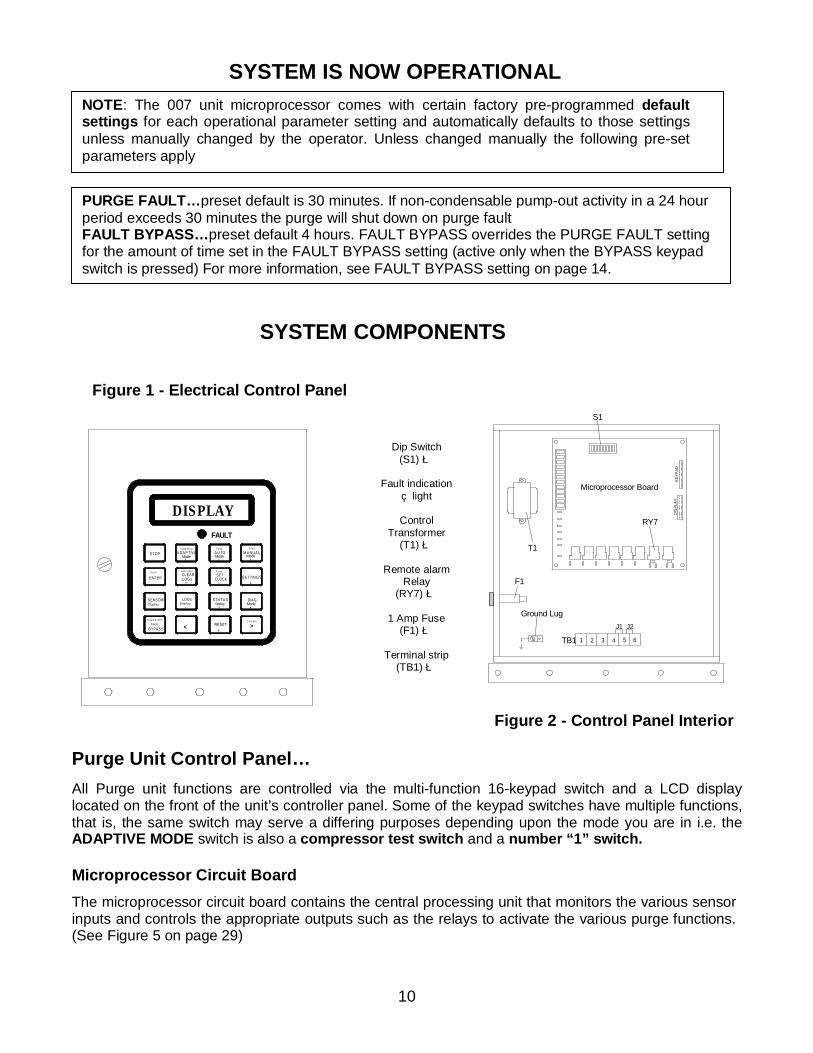
Figure 1 - Electrical Control Panel Figure 2 - Control Panel Interior
Purge Unit Control Panel… All Purge unit functions are controlled via the multi-function 16-keypad switch and a LCD display located on the front of the unit’s controller panel. Some of the keypad switches have multiple functions, that is, the same switch may serve a differing purposes depending upon the mode you are in i.e. the ADAPTIVE MODE switch is also a compressor test switch and a number “1” switch. Microprocessor Circuit Board The microprocessor circuit board contains the central processing unit that monitors the various sensor inputs and controls the appropriate outputs such as the relays to activate the various purge functions. (See Figure 5 on page 29)
Dip Switch
(S1) è
Fault indication çlight
Control
Transformer (T1) è
Remote alarm
Relay (RY7) è
1 Amp Fuse
(F1) è
Terminal strip (TB1) è
NOTE: The 007 unit microprocessor comes with certain factory pre-programmed default settings for each operational parameter setting and automatically defaults to those settings unless manually changed by the operator. Unless changed manually the following pre-set parameters apply
PURGE FAULT…preset default is 30 minutes. If non-condensable pump-out activity in a 24 hour period exceeds 30 minutes the purge will shut down on purge fault FAULT BYPASS…preset default 4 hours. FAULT BYPASS overrides the PURGE FAULT setting for the amount of time set in the FAULT BYPASS setting (active only when the BYPASS keypad switch is pressed) For more information, see FAULT BYPASS setting on page 14.
F1
1TB1
Ground Lug
42 3 5 6
J2J1
Microprocessor Board
T1
RY7
DIS
PLAY
S1
KEYP
AD
DISPLAY
BYPASSFault
Toggle O n/O ff
<
S c ro l l
ENTER
DisplaySENSORS LOGs
7Display
4
A UX V alv eCLEARLOGs
S TO P1
Mode
Com pres s or
A DA P TIV E
RESET0
>F unc tion
S E TTING S
8
S TA TUSDisplay
CLOCK
A larmSET
5
9ModeDIAG.
6
M A NUA LMode
2
P um p
A UTO D r a in
3Mode
FAULT
11
Security-Lock The purge unit is equipped with a security lock system that prevents unauthorized personnel from tampering with certain functions and settings. The purge unit comes from the factory with the security lock enabled (see Dip switch S1 settings starting on page 15).
One example of why the operator may wish to use the “Security Lock” function is that when the purge unit is operating in the ADAPTIVE mode it acquires historical data in its data LOG used to determine purging frequency. If an unauthorized person were to inadvertently clear the LOG this information would be permanently lost and the purge unit will have to run many days to re-acquire new data. When the “Security Lock” is activated unauthorized entry cannot be made. Non-condensable Pump-out Circuit… The non-condensable pump-out circuit is nearly identical to the Purifier® Purge unit consisting of a 1/20 H.P diaphragm pump-out compressor a pair of isolation solenoid valves and a flow restrictor device. When sufficient air has accumulated in the purge tank to trigger a pump-out cycle the purge controller will energize (open) both isolation solenoid valves and start the pump-out compressor. Non-condensables (air) is slowly pumped from the purge tank through the flow restrictor and discharged through the emission collection canister to the atmosphere. Removing air slowly via the flow restrictor improves purging efficiency. The pump-out compressor is compatible with refrigerants CFC-11, and HCFC-123. Liquid Drain Back Liquid drain back is “gravity flow” identical to the Purifier® / EarthWise™ Purge unit. When the purger is operating liquid flow should be visible in the liquid drain-back line sight glass. Filter Drier
NOTE: The 007 unit filter-drier is identical to the filter-drier used on the Purifier® / EarthWise™ purge units and can be can be used as a direct replacement for the Trane filter-drier. Optional Accessories Emission Collection Canister saturation alarm (option) The emission collection canister alarm is an electronic refrigerant emission monitor for use with the Redi Control’s ZERO EMISSION COLLECTION CANISTER to indicate when the canister has become saturated with refrigerant. For more information contact Equipment Servicing. Chiller mounted condenser temperature sensor TS-3 (option) Optional chiller mounted temperature sensor TS-3 is typically used with “Free-Cooling” or ice storage chillers, etc. It is used to lock-out purge operation when chiller condensing saturation temperature is below 50°F to prevent inadvertent refrigerant pump-out. For more information contact Redi Controls.
12
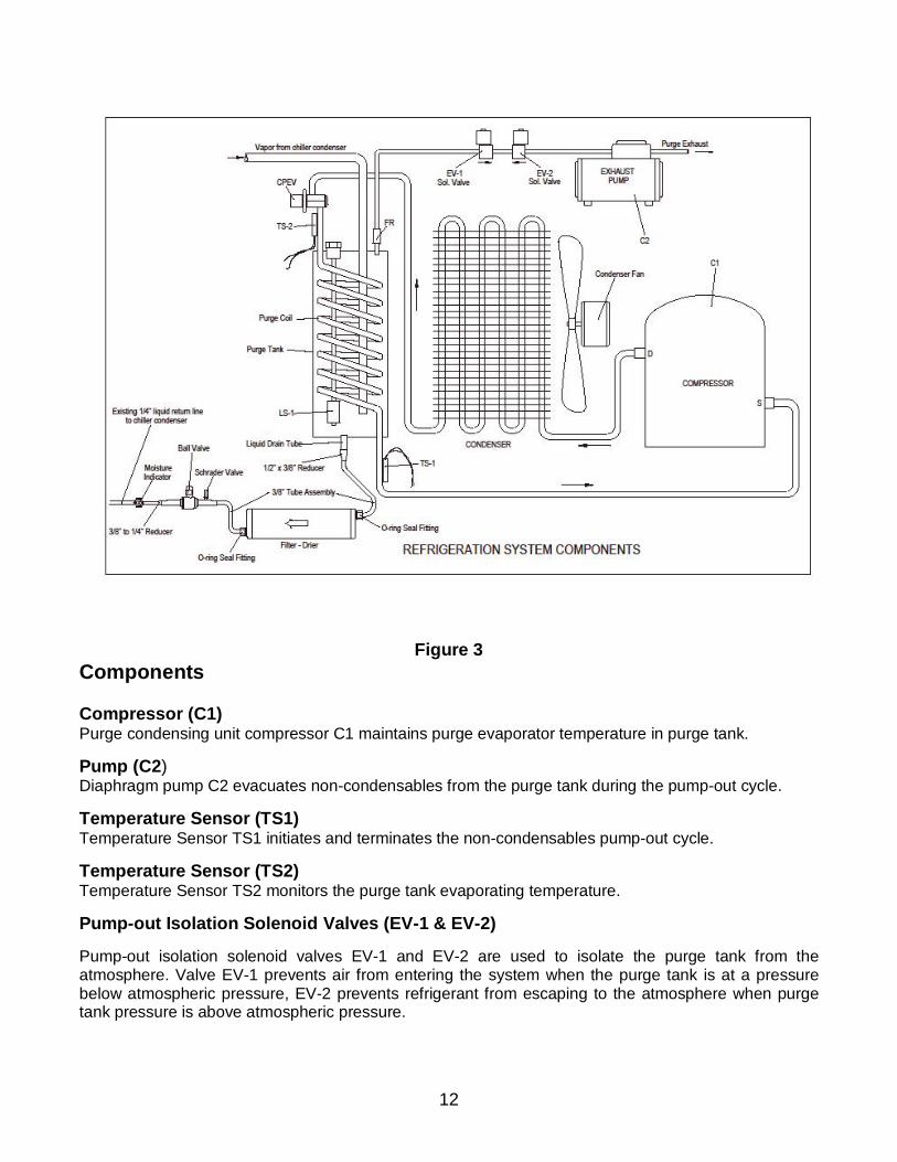
Figure 3 Components Compressor (C1) Purge condensing unit compressor C1 maintains purge evaporator temperature in purge tank. Pump (C2) Diaphragm pump C2 evacuates non-condensables from the purge tank during the pump-out cycle. Temperature Sensor (TS1) Temperature Sensor TS1 initiates and terminates the non-condensables pump-out cycle. Temperature Sensor (TS2) Temperature Sensor TS2 monitors the purge tank evaporating temperature. Pump-out Isolation Solenoid Valves (EV-1 & EV-2) Pump-out isolation solenoid valves EV-1 and EV-2 are used to isolate the purge tank from the atmosphere. Valve EV-1 prevents air from entering the system when the purge tank is at a pressure below atmospheric pressure, EV-2 prevents refrigerant from escaping to the atmosphere when purge tank pressure is above atmospheric pressure.
13
High Liquid Level Safety Switch (LS-1) High liquid level safety switch LS1 terminates and locks out purge operation when liquid level in the purge tank reaches a critical level indicating a drain problem. Remote “Purge Fault” Alarm Relay (RLY-7) Remote purge fault alarm relay RLY-7 is used to enunciate a purge fault alarm at a location remote from the purge unit. Auxiliary Relay (RLY-8)
Auxiliary relay RLY-8 is not used in the Purifier® Purge application. Terminal Block (TB-1) Terminal block TB-1 is used for field wiring to the purge unit. Control Transformer (T1) Transformer T1 is a 12 volt power transformer used to power the microprocessor circuit board.
Constant pressure expansion valve (CPEV) The constant pressure expansion valve (CPEV) regulates evaporator temperature at a constant 0°F to 5°F. Security-Lock The 007 unit is equipped with a simple security lock system that prevents unauthorized personnel from tampering with certain functions. The purge unit comes from the factory with the security lock enabled (see Dip switch S1 settings starting on page 15).
14
Setting or Changing Operating Parameters… To set or change any of the purge unit’s operating parameters temporarily switch Dip switch S1-position 4 to the “ON” position. This disables the Security Lock feature (see Figure 2 on page 10 for Dip switch S1 location). Once operational parameters are set switch S1-position 4 back to the “OFF” position. (This re-enables the Security Lock feature.)
Purge Fault setting… Switch Dip Switch S1-position 4 to the “ON” position. To set the Purge Fault time press the “SETTINGS” keypad switch and scroll the display using the SCROLL key until the display reads: Enter Max PURGE
FAULT Min.: 030 (1to 240 minutes / default 30 min)
CAUTION: Always set Purge Fault time as low as possible to limit refrigerant pump-out in the event of a malfunction.
Use the cursor movement keypad switches < > to move the cursor beneath the position you wish to change. Use the numbered keypad switches to enter the desired value then press the ENTER key. If you wish to change another operating parameter SCROLL to the appropriate display and make change. To exit the SETTINGS mode, press the STOP key and switch Dip switch S1-position 4 to the “OFF” position. Now select desired operating mode.
NOTE: When an entered value is either higher or lower than allowable for that parameter an “Error Value” message will be displayed. The purge unit’s microprocessor will then override the errant value and automatically assign the appropriate default value. Fault BYPASS setting… Switch Dip Switch S1-position 4 to the “ON” position. To set Fault Bypassed time press the “SETTINGS” keypad switch and scroll the display using the SCROLL key until the display reads: Enter FLT Bypass
Time HRS : 004 ( 1 to 72 hrs / default 4hrs) Use the cursor movement keypad switches < > to move the cursor beneath the position you wish to change. Using the numbered keypad switches enter the desired value, then press the ENTER key. To exit the SETTINGS mode, press the STOP key and switch Dip switch S1-position 4 back to the “OFF” position. Now select desired operating modes.
NOTE: When an entered value is either higher or lower than allowable for that parameter an “Error Value” message will be displayed. The purge unit’s microprocessor will then override the errant value and automatically assign the appropriate default value.
15
To activate the Fault Bypass mode press the “Fault BYPASS” keypad switch. The Fault “BYPASS” mode can be exited at any time by again pressing the Fault “BYPASS” Switch.
CAUTION: When operating in the FAULT Bypass mode there is no Purge FAULT protection, therefore, FAULT Bypass should be used sparingly and only while being monitored. Never leave the purge operating unattended while operating in FAULT Bypass.
Dip Switch S1 Settings… Dip Switch S1 only needs to be set if any of the optional sensors have been installed, or when setting operational parameters (see Figure 2 page 10 for Dip switch location).
NOTE: All dip switches must be set to the “OFF “position unless one or more of the following options are installed. Dip switch S1 “Security Lock” Dip switch S1 position 4 “OFF” activates SECURITY LOCK. The SECURITY LOCK prevents unauthorized access to the purge unit’s operational parameters by locking out the following keypad switches…CLEAR LOG and SETTINGS. Dip switch S1 “Canister Alarm” Dip switch S1position 6 “ON” activates the emission collection canister saturation alarm option (when installed). Dip switch S1 “Canister Alarm” Purge Lock-Out Option. Dip switch S1 position 3 “ON” activates the “Canister is Full Alarm” (when the emission collection canister is installed) When using this setting purge operation will cease when canister saturation alarm occurs. Microprocessor Overview…
Introduction The 007 Redi-Purge unit controller utilizes a Microprocessor to control all aspects of purge operation including self diagnostics. It also tracks, measures, stores and displays all operational data needed to manage chiller non-condensables. The following is an overview of the microprocessors features and functions. Safety Features
The Microprocessor Control provides a full array of safety features that will terminate purge operation when an abnormal condition develops in any one of the following areas: Maximum Allowable Pump-out Time Exceeded (PURGE FAULT) Purge operation is terminated and a latching "Purge Fault" diagnostic occurs when the pre-set maximum allowable purge pump-out time is exceeded during any 24-hour “sliding window” period. Sensor Operation (SENSOR ERROR) Purge operation will terminate and a latching "Sensor Error" occurs when a sensor has failed.
16
Operating Modes The purge unit has three (3) operating modes. To select desired mode press one of the following keypad switches. MANUAL mode purge operation is continuous whether chiller is on or off. The MANUAL mode is recommended ONLY during servicing or testing. AUTO mode purge operation interlocks with a chiller-generated RUN signal which provides a 120 volt signal to the purge unit’s microprocessor controller. AUTO and ADAPTIVE mode operation is identical except that in AUTO mode purge operation is active only while the chiller is running. ADAPTIVE mode activates the purge’s "self-learning” Duty Cycle function. In this mode the microprocessor continually monitors and records a history of all non-condensable pump-out activity and automatically uses that “recorded” information to "Duty Cycle" future purge operation based upon its "learned" purging needs. This minimizes both energy usage and wear on the unit. When in the "Adaptive" mode, the purge system is enabled (enabled does not mean purging) at all times, and is independent of the operational status of the chiller, and will purge “as needed” whether chiller is "ON" or “OFF”. The microprocessor’s “self-learning” function utilizes a “daily” average non-condensables pump-out time (based only on the last 30 day history) to determine the number of “ON” purging cycles required for any given 24 hour period. The greater the historical average pump-out time the greater the number of “ON” purging cycles per day required, the less the historical average pump-out time, the less “ON” purging cycles per day required. When the purge is first installed, or anytime after its data base Log has been cleared, purge operation will begin with 8 “ON” purging cycles per day and adjusts according to the pump-out history. Each “ON” purging cycle is for a minimum of 30 minutes. The purge “learns” by the following process. During the last 15 minutes of an “ON” purging cycle, if any non condensable pump-out activity occurs, the “ON” period is automatically extended 15 minutes. The “ON” purging Cycle period will continue extending itself until all non-condensable pump-out activity has ceased. If the “ON” Cycle continues extending indefinitely, there is probably a problem with either the chiller or the purge system which requires attention.
17
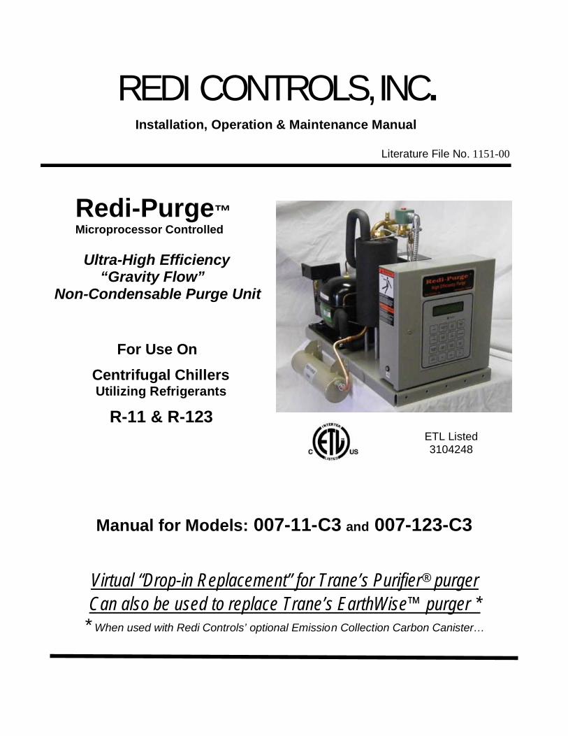
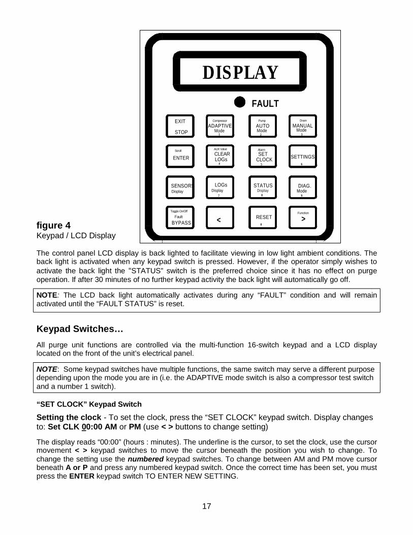
figure 4 Keypad / LCD Display The control panel LCD display is back lighted to facilitate viewing in low light ambient conditions. The back light is activated when any keypad switch is pressed. However, if the operator simply wishes to activate the back light the “STATUS” switch is the preferred choice since it has no effect on purge operation. If after 30 minutes of no further keypad activity the back light will automatically go off.
NOTE: The LCD back light automatically activates during any “FAULT” condition and will remain activated until the “FAULT STATUS” is reset.
Keypad Switches… All purge unit functions are controlled via the multi-function 16-switch keypad and a LCD display located on the front of the unit’s electrical panel.
NOTE: Some keypad switches have multiple functions, the same switch may serve a different purpose depending upon the mode you are in (i.e. the ADAPTIVE mode switch is also a compressor test switch and a number 1 switch).
“SET CLOCK” Keypad Switch
Setting the clock - To set the clock, press the “SET CLOCK” keypad switch. Display changes to: Set CLK 00:00 AM or PM (use < > buttons to change setting) The display reads “00:00” (hours : minutes). The underline is the cursor, to set the clock, use the cursor movement < > keypad switches to move the cursor beneath the position you wish to change. To change the setting use the numbered keypad switches. To change between AM and PM move cursor beneath A or P and press any numbered keypad switch. Once the correct time has been set, you must press the ENTER keypad switch TO ENTER NEW SETTING.
DISPLAY
Display Display
FaultBYPASS
Toggle On/Off
<
7
SENSORS
Scroll
ENTER4
LOGs
AUX Valve
CLEARLOGs
EXIT
STOP 1
ADAPTIVEMode
Compressor
Display Mode
RESET0
8
>Function
9
5
STATUS
CLOCK
AlarmSET
6
DIAG.
SETTINGS
2Mode
Pump
AUTO
FAULT
3
MANUAL Drain
Mode
18
Once the current time has been set you MUST press the ENTER keypad switch.
Display changes to: System ready Select Mode:
Alternating with: System ready Example: 07:12 AM (current clock time)
NOTE: The SET CLOCK display will automatically be exited after 30 seconds of no Keypad activity.
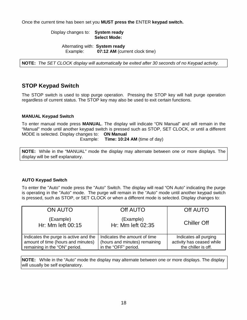
STOP Keypad Switch The STOP switch is used to stop purge operation. Pressing the STOP key will halt purge operation regardless of current status. The STOP key may also be used to exit certain functions. MANUAL Keypad Switch To enter manual mode press MANUAL. The display will indicate “ON Manual” and will remain in the “Manual" mode until another keypad switch is pressed such as STOP, SET CLOCK, or until a different MODE is selected. Display changes to: ON Manual Example: Time: 10:24 AM (time of day) NOTE: While in the “MANUAL” mode the display may alternate between one or more displays. The display will be self explanatory. AUTO Keypad Switch To enter the "Auto" mode press the "Auto" Switch. The display will read “ON Auto” indicating the purge is operating in the "Auto" mode. The purge will remain in the “Auto" mode until another keypad switch is pressed, such as STOP, or SET CLOCK or when a different mode is selected. Display changes to:
ON AUTO (Example)
Hr: Mm left 00:15
Off AUTO (Example)
Hr: Mm left 02:35
Off AUTO
Chiller Off
Indicates the purge is active and the amount of time (hours and minutes) remaining in the “ON” period.
Indicates the amount of time (hours and minutes) remaining in the “OFF” period.
Indicates all purging activity has ceased while
the chiller is off. NOTE: While in the “Auto” mode the display may alternate between one or more displays. The display will usually be self explanatory.
19
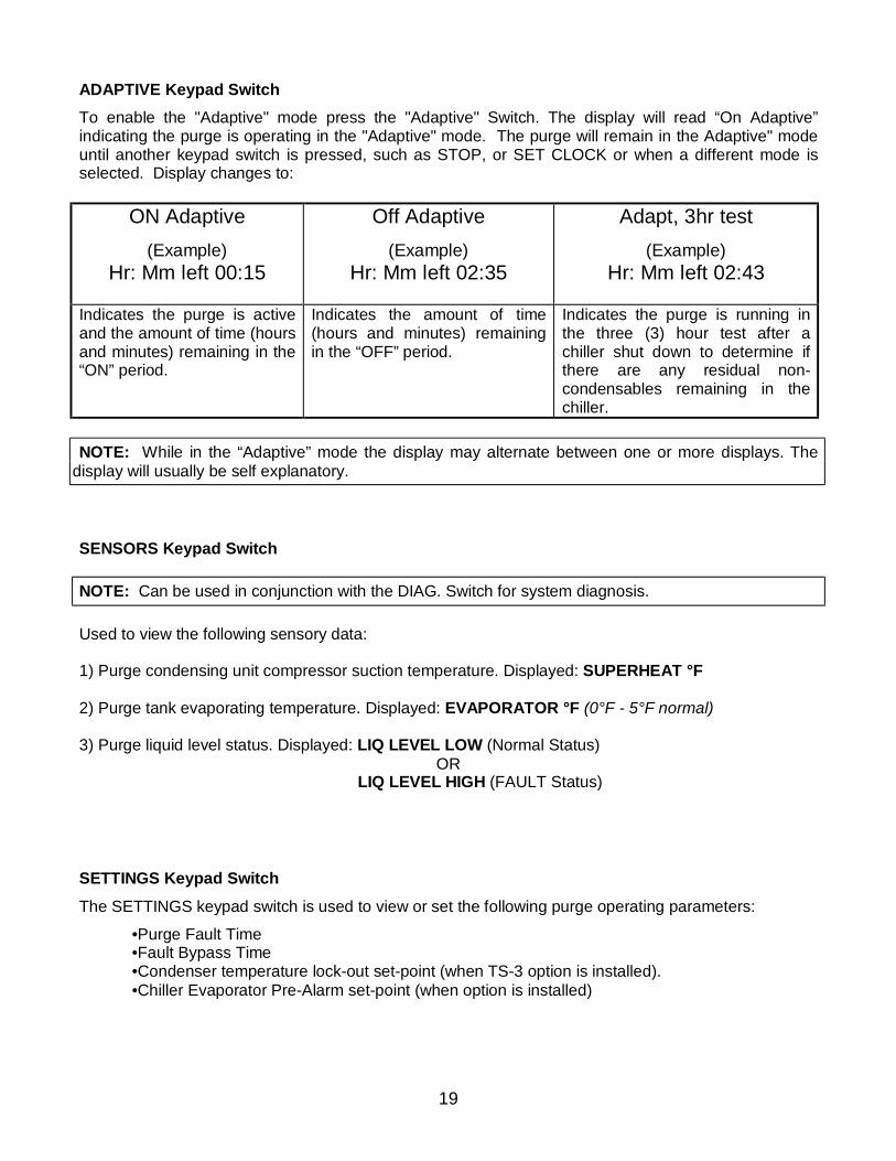
ADAPTIVE Keypad Switch To enable the "Adaptive" mode press the "Adaptive" Switch. The display will read “On Adaptive” indicating the purge is operating in the "Adaptive" mode. The purge will remain in the Adaptive" mode until another keypad switch is pressed, such as STOP, or SET CLOCK or when a different mode is selected. Display changes to:
ON Adaptive (Example)
Hr: Mm left 00:15
Off Adaptive (Example)
Hr: Mm left 02:35
Adapt, 3hr test (Example)
Hr: Mm left 02:43
Indicates the purge is active and the amount of time (hours and minutes) remaining in the “ON” period.
Indicates the amount of time (hours and minutes) remaining in the “OFF” period.
Indicates the purge is running in the three (3) hour test after a chiller shut down to determine if there are any residual non-condensables remaining in the chiller.
NOTE: While in the “Adaptive” mode the display may alternate between one or more displays. The
display will usually be self explanatory. SENSORS Keypad Switch NOTE: Can be used in conjunction with the DIAG. Switch for system diagnosis. Used to view the following sensory data: 1) Purge condensing unit compressor suction temperature. Displayed: SUPERHEAT °F 2) Purge tank evaporating temperature. Displayed: EVAPORATOR °F (0°F - 5°F normal) 3) Purge liquid level status. Displayed: LIQ LEVEL LOW (Normal Status)
OR LIQ LEVEL HIGH (FAULT Status) SETTINGS Keypad Switch
The SETTINGS keypad switch is used to view or set the following purge operating parameters:
•Purge Fault Time •Fault Bypass Time •Condenser temperature lock-out set-point (when TS-3 option is installed). •Chiller Evaporator Pre-Alarm set-point (when option is installed)
20
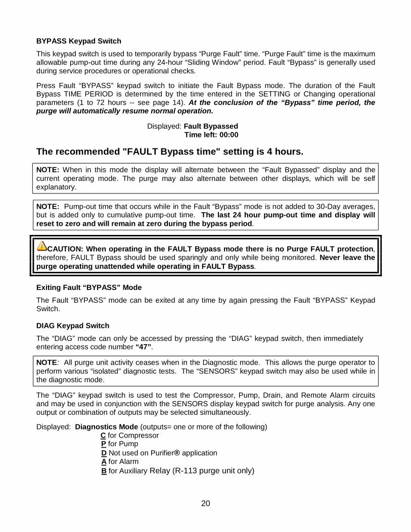
BYPASS Keypad Switch This keypad switch is used to temporarily bypass “Purge Fault” time. “Purge Fault” time is the maximum allowable pump-out time during any 24-hour “Sliding Window” period. Fault “Bypass” is generally used during service procedures or operational checks. Press Fault “BYPASS” keypad switch to initiate the Fault Bypass mode. The duration of the Fault Bypass TIME PERIOD is determined by the time entered in the SETTING or Changing operational parameters (1 to 72 hours -- see page 14). At the conclusion of the “Bypass” time period, the purge will automatically resume normal operation. Displayed: Fault Bypassed Time left: 00:00 The recommended "FAULT Bypass time" setting is 4 hours.
NOTE: When in this mode the display will alternate between the “Fault Bypassed” display and the current operating mode. The purge may also alternate between other displays, which will be self explanatory.
NOTE: Pump-out time that occurs while in the Fault “Bypass” mode is not added to 30-Day averages, but is added only to cumulative pump-out time. The last 24 hour pump-out time and display will reset to zero and will remain at zero during the bypass period.
CAUTION: When operating in the FAULT Bypass mode there is no Purge FAULT protection, therefore, FAULT Bypass should be used sparingly and only while being monitored. Never leave the purge operating unattended while operating in FAULT Bypass.
Exiting Fault “BYPASS” Mode The Fault “BYPASS” mode can be exited at any time by again pressing the Fault “BYPASS” Keypad Switch. DIAG Keypad Switch The “DIAG” mode can only be accessed by pressing the “DIAG” keypad switch, then immediately entering access code number “47”.
NOTE: All purge unit activity ceases when in the Diagnostic mode. This allows the purge operator to perform various “isolated” diagnostic tests. The “SENSORS” keypad switch may also be used while in the diagnostic mode.
The “DIAG” keypad switch is used to test the Compressor, Pump, Drain, and Remote Alarm circuits and may be used in conjunction with the SENSORS display keypad switch for purge analysis. Any one output or combination of outputs may be selected simultaneously. Displayed: Diagnostics Mode (outputs= one or more of the following) C for Compressor P for Pump D Not used on Purifier® application A for Alarm B for Auxiliary Relay (R-113 purge unit only)
21
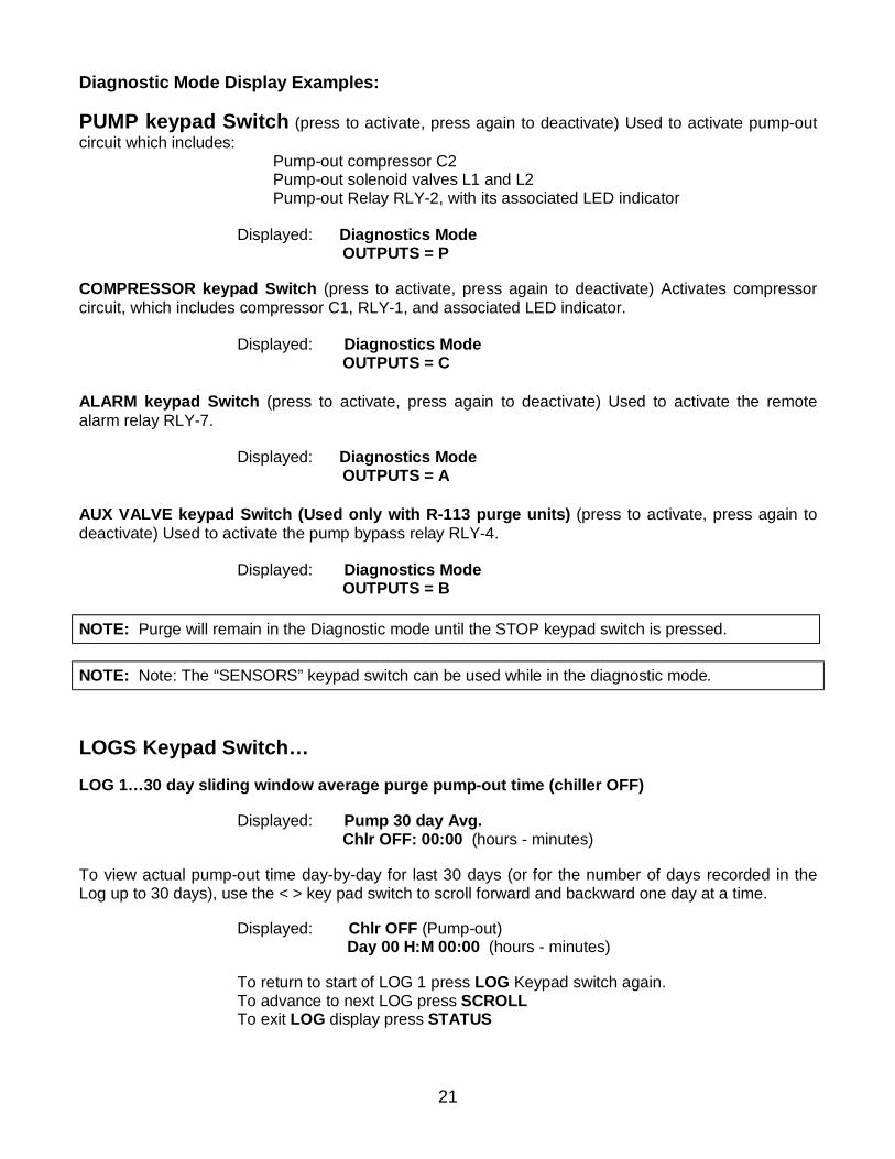
Diagnostic Mode Display Examples: PUMP keypad Switch (press to activate, press again to deactivate) Used to activate pump-out circuit which includes: Pump-out compressor C2 Pump-out solenoid valves L1 and L2 Pump-out Relay RLY-2, with its associated LED indicator Displayed: Diagnostics Mode OUTPUTS = P COMPRESSOR keypad Switch (press to activate, press again to deactivate) Activates compressor circuit, which includes compressor C1, RLY-1, and associated LED indicator. Displayed: Diagnostics Mode OUTPUTS = C ALARM keypad Switch (press to activate, press again to deactivate) Used to activate the remote alarm relay RLY-7. Displayed: Diagnostics Mode OUTPUTS = A AUX VALVE keypad Switch (Used only with R-113 purge units) (press to activate, press again to deactivate) Used to activate the pump bypass relay RLY-4. Displayed: Diagnostics Mode OUTPUTS = B NOTE: Purge will remain in the Diagnostic mode until the STOP keypad switch is pressed. NOTE: Note: The “SENSORS” keypad switch can be used while in the diagnostic mode. LOGS Keypad Switch… LOG 1…30 day sliding window average purge pump-out time (chiller OFF) Displayed: Pump 30 day Avg. Chlr OFF: 00:00 (hours - minutes) To view actual pump-out time day-by-day for last 30 days (or for the number of days recorded in the Log up to 30 days), use the < > key pad switch to scroll forward and backward one day at a time. Displayed: Chlr OFF (Pump-out) Day 00 H:M 00:00 (hours - minutes)
To return to start of LOG 1 press LOG Keypad switch again. To advance to next LOG press SCROLL To exit LOG display press STATUS
22
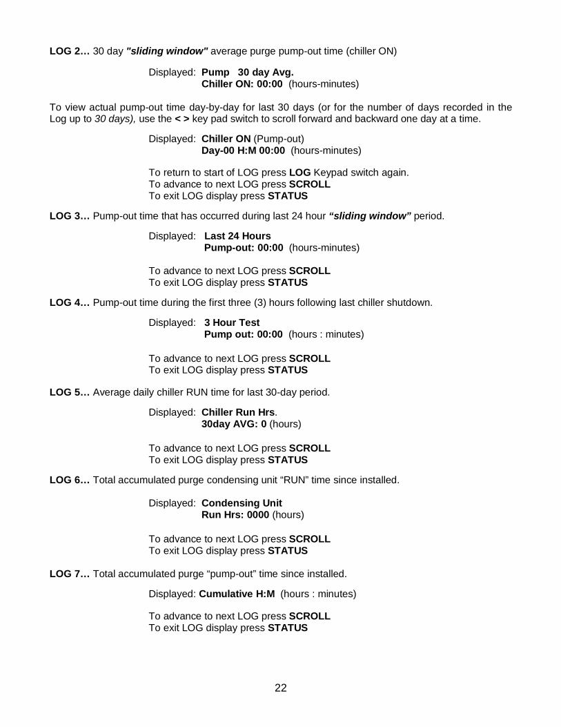
LOG 2… 30 day "sliding window" average purge pump-out time (chiller ON) Displayed: Pump 30 day Avg. Chiller ON: 00:00 (hours-minutes) To view actual pump-out time day-by-day for last 30 days (or for the number of days recorded in the Log up to 30 days), use the < > key pad switch to scroll forward and backward one day at a time. Displayed: Chiller ON (Pump-out) Day-00 H:M 00:00 (hours-minutes)
To return to start of LOG press LOG Keypad switch again. To advance to next LOG press SCROLL To exit LOG display press STATUS
LOG 3… Pump-out time that has occurred during last 24 hour “sliding window” period. Displayed: Last 24 Hours Pump-out: 00:00 (hours-minutes)
To advance to next LOG press SCROLL To exit LOG display press STATUS
LOG 4… Pump-out time during the first three (3) hours following last chiller shutdown. Displayed: 3 Hour Test Pump out: 00:00 (hours : minutes)
To advance to next LOG press SCROLL To exit LOG display press STATUS
LOG 5… Average daily chiller RUN time for last 30-day period.
Displayed: Chiller Run Hrs. 30day AVG: 0 (hours)
To advance to next LOG press SCROLL To exit LOG display press STATUS
LOG 6… Total accumulated purge condensing unit “RUN” time since installed.
Displayed: Condensing Unit Run Hrs: 0000 (hours)
To advance to next LOG press SCROLL To exit LOG display press STATUS
LOG 7… Total accumulated purge “pump-out” time since installed.
Displayed: Cumulative H:M (hours : minutes)
To advance to next LOG press SCROLL To exit LOG display press STATUS
23
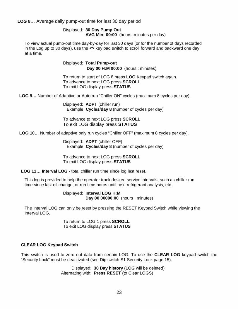
LOG 8… Average daily pump-out time for last 30 day period Displayed: 30 Day Pump Out AVG Min: 00:00 (hours :minutes per day)
To view actual pump-out time day-by-day for last 30 days (or for the number of days recorded in the Log up to 30 days), use the <> key pad switch to scroll forward and backward one day at a time.
Displayed: Total Pump-out Day 00 H:M 00:00 (hours : minutes)
To return to start of LOG 8 press LOG Keypad switch again. To advance to next LOG press SCROLL To exit LOG display press STATUS
LOG 9… Number of Adaptive or Auto run “Chiller ON” cycles (maximum 8 cycles per day).
Displayed: ADPT (chiller run)
Example: Cycles/day 8 (number of cycles per day)
To advance to next LOG press SCROLL To exit LOG display press STATUS
LOG 10… Number of adaptive only run cycles “Chiller OFF” (maximum 8 cycles per day). Displayed: ADPT (chiller OFF)
Example: Cycles/day 8 (number of cycles per day) To advance to next LOG press SCROLL To exit LOG display press STATUS
LOG 11… Interval LOG - total chiller run time since log last reset.
This log is provided to help the operator track desired service intervals, such as chiller run time since last oil change, or run time hours until next refrigerant analysis, etc.
Displayed: Interval LOG H:M Day 00 00000:00 (hours : minutes)
The Interval LOG can only be reset by pressing the RESET Keypad Switch while viewing the Interval LOG.
To return to LOG 1 press SCROLL To exit LOG display press STATUS
CLEAR LOG Keypad Switch This switch is used to zero out data from certain LOG. To use the CLEAR LOG keypad switch the “Security Lock” must be deactivated (see Dip switch S1 Security Lock page 15). Displayed: 30 Day history (LOG will be deleted) Alternating with: Press RESET (to Clear LOGS)
24
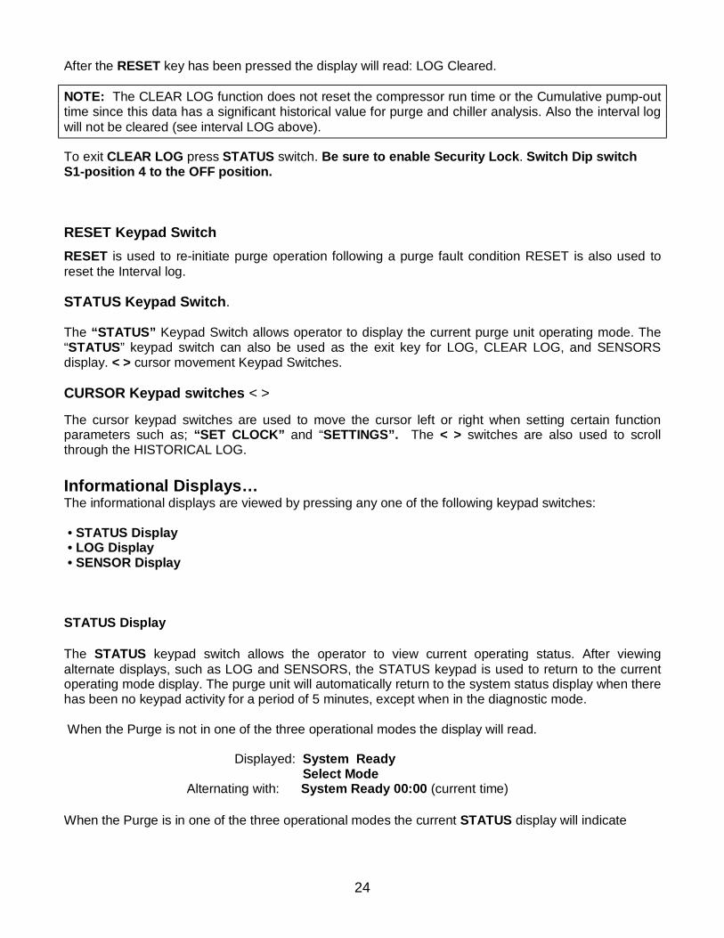
After the RESET key has been pressed the display will read: LOG Cleared.
NOTE: The CLEAR LOG function does not reset the compressor run time or the Cumulative pump-out time since this data has a significant historical value for purge and chiller analysis. Also the interval log will not be cleared (see interval LOG above). To exit CLEAR LOG press STATUS switch. Be sure to enable Security Lock. Switch Dip switch S1-position 4 to the OFF position. RESET Keypad Switch RESET is used to re-initiate purge operation following a purge fault condition RESET is also used to reset the Interval log. STATUS Keypad Switch. The “STATUS” Keypad Switch allows operator to display the current purge unit operating mode. The “STATUS” keypad switch can also be used as the exit key for LOG, CLEAR LOG, and SENSORS display. < > cursor movement Keypad Switches. CURSOR Keypad switches < > The cursor keypad switches are used to move the cursor left or right when setting certain function parameters such as; “SET CLOCK” and “SETTINGS”. The < > switches are also used to scroll through the HISTORICAL LOG. Informational Displays… The informational displays are viewed by pressing any one of the following keypad switches: • STATUS Display • LOG Display • SENSOR Display STATUS Display The STATUS keypad switch allows the operator to view current operating status. After viewing alternate displays, such as LOG and SENSORS, the STATUS keypad is used to return to the current operating mode display. The purge unit will automatically return to the system status display when there has been no keypad activity for a period of 5 minutes, except when in the diagnostic mode. When the Purge is not in one of the three operational modes the display will read. Displayed: System Ready Select Mode Alternating with: System Ready 00:00 (current time) When the Purge is in one of the three operational modes the current STATUS display will indicate
25
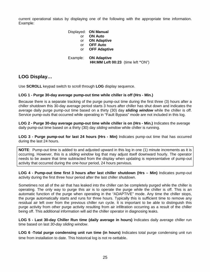
current operational status by displaying one of the following with the appropriate time information. Example: Displayed: ON Manual or ON Auto or ON Adaptive or OFF Auto or OFF Adaptive Example: ON Adaptive HH:MM Left 00:23 (time left “ON”)
LOG Display… Use SCROLL keypad switch to scroll through LOG display sequence. LOG 1 - Purge 30-day average pump-out time while chiller is off (Hrs - Min.) Because there is a separate tracking of the purge pump-out time during the first three (3) hours after a chiller shutdown this 30-day average period starts 3 hours after chiller has shut down and indicates the average daily purge pump-out time based on a thirty (30) day sliding window while the chiller is off. Service pump-outs that occurred while operating in “Fault Bypass” mode are not included in this log. LOG 2 - Purge 30-day average pump-out time while chiller is on (Hrs - Min.) Indicates the average daily pump-out time based on a thirty (30) day sliding window while chiller is running. LOG 3 - Purge pump-out for last 24 hours (Hrs - Min) Indicates pump-out time that has occurred during the last 24 hours.
NOTE: Pump-out time is added to and adjusted upward in this log in one (1) minute increments as it is occurring. However, this is a sliding window log that may adjust itself downward hourly. The operator needs to be aware that time subtracted from the display when updating is representative of pump-out activity that occurred during the one-hour period, 24 hours pervious. LOG 4 - Pump-out time first 3 hours after last chiller shutdown (Hrs – Min) Indicates pump-out activity during the first three hour period after the last chiller shutdown. Sometimes not all of the air that has leaked into the chiller can be completely purged while the chiller is operating. The only way to purge this air is to operate the purge while the chiller is off. This is an automatic function of the purge when operating in the “ADAPTIVE” mode. Any time the chiller stops, the purge automatically starts and runs for three hours. Typically this is sufficient time to remove any residual air left over from the previous chiller run cycle. It is important to be able to distinguish this purge activity from other purge activity resulting from air infiltration occurring as a result of the chiller being off. This additional information will aid the chiller operator in diagnosing leaks. LOG 5 - Last 30-day Chiller Run time (daily average in hours) Indicates daily average chiller run time based on last 30-day sliding window. LOG 6 -Total purge condensing unit run time (in hours) Indicates total purge condensing unit run time from installation to date. This historical log is not re-settable.
26
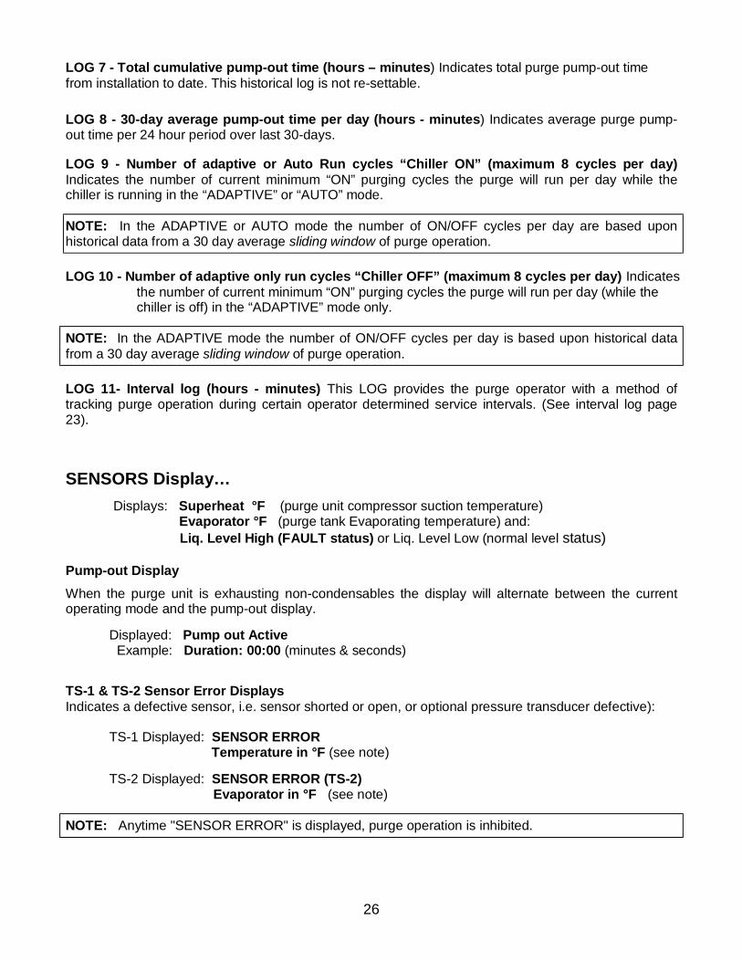
LOG 7 - Total cumulative pump-out time (hours – minutes) Indicates total purge pump-out time from installation to date. This historical log is not re-settable.
LOG 8 - 30-day average pump-out time per day (hours - minutes) Indicates average purge pump-out time per 24 hour period over last 30-days. LOG 9 - Number of adaptive or Auto Run cycles “Chiller ON” (maximum 8 cycles per day) Indicates the number of current minimum “ON” purging cycles the purge will run per day while the chiller is running in the “ADAPTIVE” or “AUTO” mode.
NOTE: In the ADAPTIVE or AUTO mode the number of ON/OFF cycles per day are based upon historical data from a 30 day average sliding window of purge operation. LOG 10 - Number of adaptive only run cycles “Chiller OFF” (maximum 8 cycles per day) Indicates
the number of current minimum “ON” purging cycles the purge will run per day (while the chiller is off) in the “ADAPTIVE” mode only.
NOTE: In the ADAPTIVE mode the number of ON/OFF cycles per day is based upon historical data from a 30 day average sliding window of purge operation. LOG 11- Interval log (hours - minutes) This LOG provides the purge operator with a method of tracking purge operation during certain operator determined service intervals. (See interval log page 23). SENSORS Display…
Displays: Superheat °F (purge unit compressor suction temperature) Evaporator °F (purge tank Evaporating temperature) and: Liq. Level High (FAULT status) or Liq. Level Low (normal level status)
Pump-out Display When the purge unit is exhausting non-condensables the display will alternate between the current operating mode and the pump-out display.
Displayed: Pump out Active Example: Duration: 00:00 (minutes & seconds)
TS-1 & TS-2 Sensor Error Displays Indicates a defective sensor, i.e. sensor shorted or open, or optional pressure transducer defective):
TS-1 Displayed: SENSOR ERROR Temperature in °F (see note) TS-2 Displayed: SENSOR ERROR (TS-2) Evaporator in °F (see note)
NOTE: Anytime "SENSOR ERROR" is displayed, purge operation is inhibited.
27
FAULT Indications… PURGE FAULT Indicates maximum allowed pump-out time during any 24 hour sliding window period has been exceeded. Displayed: PURGE FAULT When purge pump-out time exceeds pre-set maximum allowed pump-out time the purge will Lock-Out in a PURGE FAULT condition. DRAIN FAULT Indicates the purge is "OFF" in a high liquid level drain fault condition. Displayed: DRAIN FAULT If the High Liquid Level Switch LS-1 senses excessive liquid build-up in the purge tank the display will indicate liquid HIGH level. If after 10 minutes LS-1 still senses a high liquid level the purger will shutdown in a Drain FAULT condition. BATTERY FAULT Indicates purge is "OFF" in a battery fault condition. Displayed: BATTERY FAULT The Microprocessor Controller incorporates a permanent self-charging battery backup that prevents loss of critical data during power down periods or power failure. The battery back-up will maintain stored data and parameters for approximately 30 days. When a “BATTERY FAULT” has occurred, all fault parameters settings will revert to their factory default setting. All information stored in the operational data LOG as well as clock time will also be lost and will have to be reset.
28
MAINTENANCE This section discusses purge system maintenance requirements and procedures, and basic purger troubleshooting procedures.
Periodic Maintenance… The following maintenance procedures are required to assure efficient and reliable operation of the 007 Redi-Purge System.
WARNING! Certain servicing procedures expose you to refrigerant. To minimize the possibility of injury, follow the safety procedures on the label and in the material safety data sheet for the refrigerant.
Weekly With chiller operating, visually check the liquid return line moisture indicator. If after 72 hours of chiller/purge operating time refrigerant indicates moist the filter-drier is saturated and should be replaced. Following filter/drier replacement wait a minimum of 72 hours of chiller/purge operating time to determine current moisture condition. NOTE: Always dispose of the old filter-drier in accordance with local regulations. Replacing liquid return line filter-drier…
1. Turn purge unit OFF and isolate from chiller. 2. Utilizing Schrader fitting on isolation ball valve at outlet end of filter-drier recover refrigerant from filter-drier and purge system using proper refrigerant recovery equipment and recommended recovery procedures
WARNING! Handling refrigerants can be a serious health hazard and potentially cause death. NEVER drain liquid refrigerant into an open container or the atmosphere. Both liquid and gaseous refrigerant MUST be fully recovered utilizing proper refrigerant recovery equipment in accordance with recommended refrigerant recovery procedures.
3. Remove old filter-drier and install new replacement filter-drier and O-ring seal fitting O-rings. 4. Evacuate filter-drier/purge system approximately 30 minutes. 4. Re-open isolation valves. 5. Restart Purge by selecting either the "AUTO" or “ADAPTIVE” mode. NOTE: Always dispose of the old filter-drier in accordance with local regulations.
Semi-Annually
1. Clean the air-cooled condenser coils using compressed air blowing from coil from the fan-side. 2. Typically the liquid line filter drier will require replacing semi-annually. However, the filter-drier
should be replaced no less than once annually for adequate chiller protection.
29
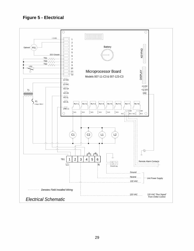
Figure 5 - Electrical
From Chiller Control120 VAC "Run Signal"
Unit Power Supply
Remote Alarm Contacts
N.C. N.C.N.O. N.O.
4
C2
TB1 1 2 3
Electrical Schematic
Denotes Field Installed Wiring
L1
C1
5 6
Ground LugN
120 VAC
120 VAC
Ground
Neutral
J1 J2
L1 L2
Microprocessor BoardModels 007-11-C3 & 007-123-C3
LS1
T1
1 Amp / 250 V
F1RLY-2
N.O.N.O.
RLY-1
ACI-2H
ACI-1L
LINE L1
ACI-2L
10
ACI-1H
1112
12 VAC
12 VAC
DCV Ground
TS2
Optional PS1
TS1TS3
3
9
4
678
5
12
+ 5 VDC
N.O. N.O.N.O. N.O.
RLY-3 RLY-5RLY-4 RLY-6
+12 VDC
RLY-7
COM
GND
RLY-8
COM
DISP
LAY
+6 VDC
Battery
KEYP
AD
30
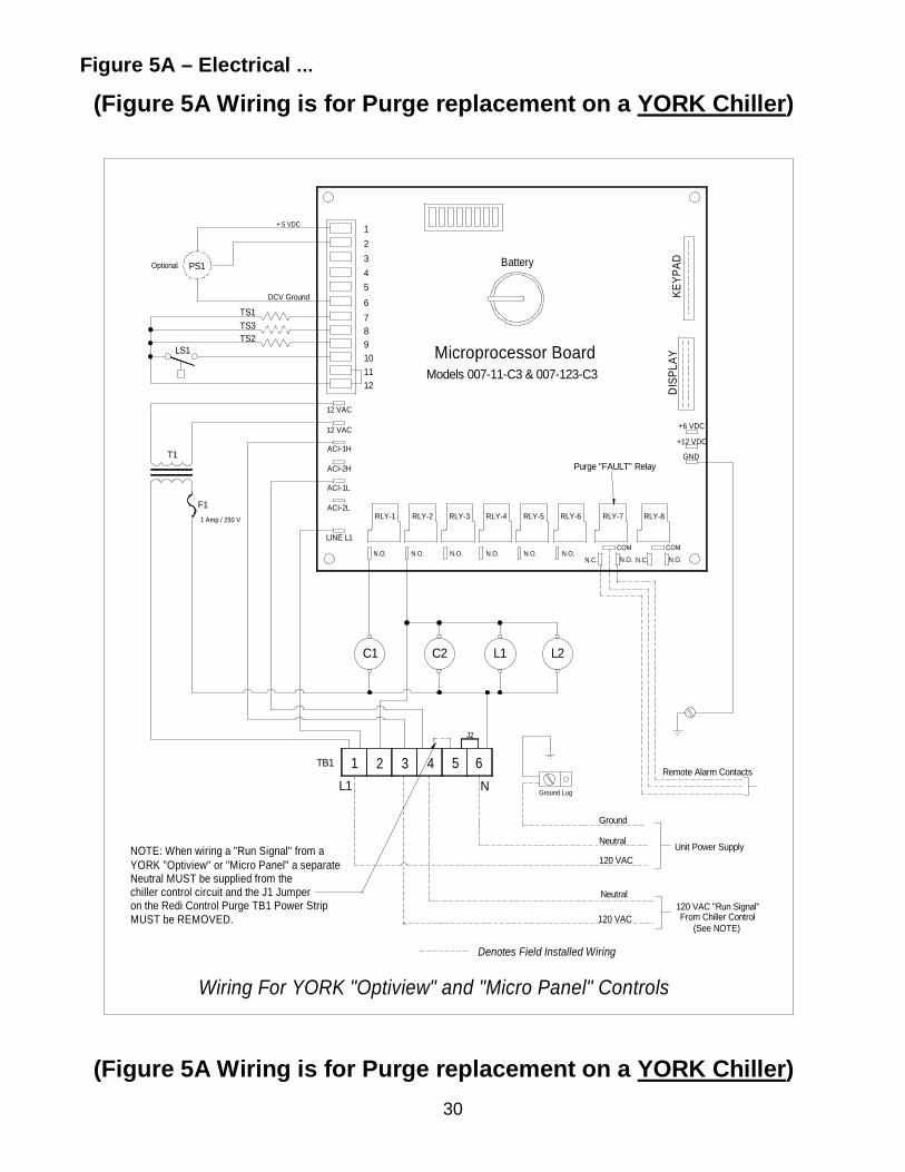
Figure 5A – Electrical …
(Figure 5A Wiring is for Purge replacement on a YORK Chiller)
(Figure 5A Wiring is for Purge replacement on a YORK Chiller)
Wiring For YORK "Optiview" and "Micro Panel" Controls
4
C2
on the Redi Control Purge TB1 Power Strip
YORK "Optiview" or "Micro Panel" a separateNOTE: When wiring a "Run Signal" from a
chiller control circuit and the J1 JumperNeutral MUST be supplied from the
MUST be REMOVED.
L1
1TB1 2 3
C1
Neutral
120 VAC
Neutral
120 VAC
Ground
Denotes Field Installed Wiring
From Chiller Control(See NOTE)
Unit Power Supply
120 VAC "Run Signal"
N Ground Lug
5 6
J2
L1 L2
Remote Alarm Contacts
Microprocessor BoardModels 007-11-C3 & 007-123-C3
LS1 9
1 Amp / 250 V
F1
T1
N.O.
RLY-2RLY-1
ACI-1L
ACI-2L
LINE L1
N.O.
ACI-2H
12
1011
12 VAC
12 VAC
ACI-1H
TS1TS3TS2
Optional PS1
DCV Ground
4
678
5
23
+ 5 VDC 1
RLY-7
Purge "FAULT" Relay
RLY-4
N.O.
RLY-6
N.O.
RLY-5
N.O.N.C.
N.O.
RLY-3 RLY-8
COM COM
N.O. N.C. N.O.
DIS
PLAY
GND
+6 VDC
+12 VDC
Battery
KEYP
AD
31
TROUBLE SHOOTING
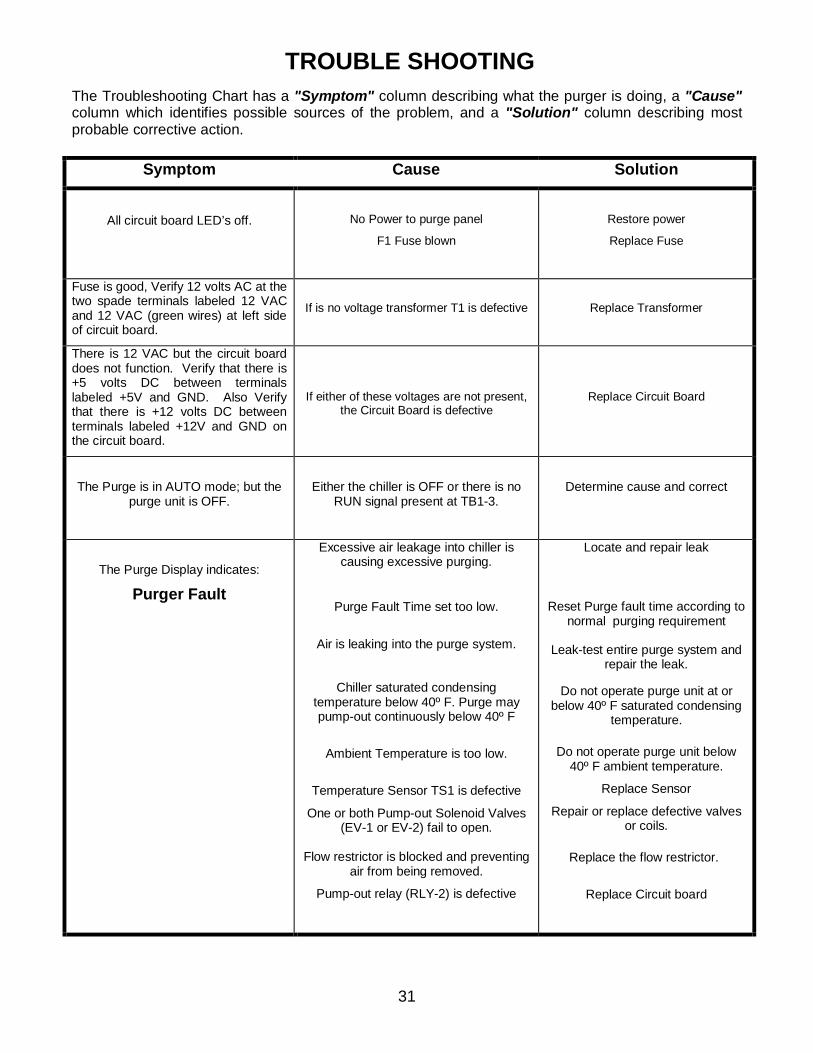
The Troubleshooting Chart has a "Symptom" column describing what the purger is doing, a "Cause" column which identifies possible sources of the problem, and a "Solution" column describing most probable corrective action.
Symptom Cause Solution
All circuit board LED’s off.
No Power to purge panel
F1 Fuse blown
Restore power
Replace Fuse
Fuse is good, Verify 12 volts AC at the two spade terminals labeled 12 VAC and 12 VAC (green wires) at left side of circuit board.
If is no voltage transformer T1 is defective
Replace Transformer
There is 12 VAC but the circuit board does not function. Verify that there is +5 volts DC between terminals labeled +5V and GND. Also Verify that there is +12 volts DC between terminals labeled +12V and GND on the circuit board.
If either of these voltages are not present, the Circuit Board is defective
Replace Circuit Board
The Purge is in AUTO mode; but the purge unit is OFF.
Either the chiller is OFF or there is no RUN signal present at TB1-3.
Determine cause and correct
The Purge Display indicates:
Purger Fault
Excessive air leakage into chiller is causing excessive purging.
Purge Fault Time set too low.
Air is leaking into the purge system.
Chiller saturated condensing temperature below 40º F. Purge may pump-out continuously below 40º F
Ambient Temperature is too low.
Temperature Sensor TS1 is defective
One or both Pump-out Solenoid Valves (EV-1 or EV-2) fail to open.
Flow restrictor is blocked and preventing
air from being removed.
Pump-out relay (RLY-2) is defective
Locate and repair leak
Reset Purge fault time according to normal purging requirement
Leak-test entire purge system and repair the leak.
Do not operate purge unit at or
below 40º F saturated condensing temperature.
Do not operate purge unit below
40º F ambient temperature.
Replace Sensor
Repair or replace defective valves or coils.
Replace the flow restrictor.
Replace Circuit board
32
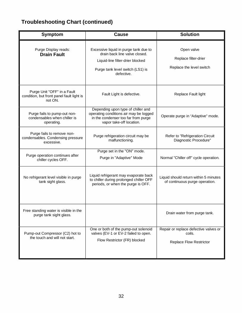
Troubleshooting Chart (continued)
Symptom Cause Solution
Purge Display reads: Drain Fault
Excessive liquid in purge tank due to drain back line valve closed.
Liquid-line filter-drier blocked
Purge tank level switch (LS1) is defective.
Open valve
Replace filter-drier
Replace the level switch
Purge Unit "OFF" in a Fault
condition, but front panel fault light is not ON.
Fault Light is defective.
Replace Fault light
Purge fails to pump-out non-condensables when chiller is
operating.
Depending upon type of chiller and operating conditions air may be logged
in the condenser too far from purge vapor take-off location.
Operate purge in “Adaptive” mode.
Purge fails to remove non-
condensables. Condensing pressure excessive.
Purge refrigeration circuit may be malfunctioning.
Refer to "Refrigeration Circuit Diagnostic Procedure"
Purge operation continues after
chiller cycles OFF.
Purge set in the "ON" mode.
Purge in "Adaptive" Mode
Normal "Chiller off" cycle operation.
No refrigerant level visible in purge
tank sight glass.
Liquid refrigerant may evaporate back to chiller during prolonged chiller OFF
periods, or when the purge is OFF.
Liquid should return within 5 minutes
of continuous purge operation.
Free standing water is visible in the
purge tank sight glass.
Drain water from purge tank.
Pump-out Compressor (C2) hot to
the touch and will not start.
One or both of the pump-out solenoid valves (EV-1 or EV-2 failed to open.
Flow Restrictor (FR) blocked
Repair or replace defective valves or coils.
Replace Flow Restrictor
33
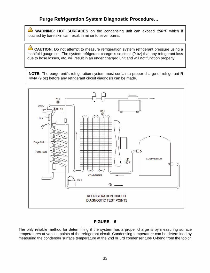
Purge Refrigeration System Diagnostic Procedure…
FIGURE – 6 The only reliable method for determining if the system has a proper charge is by measuring surface temperatures at various points of the refrigerant circuit. Condensing temperature can be determined by measuring the condenser surface temperature at the 2nd or 3rd condenser tube U-bend from the top on
NOTE: The purge unit’s refrigeration system must contain a proper charge of refrigerant R-404a (9 oz) before any refrigerant circuit diagnosis can be made.
CAUTION: Do not attempt to measure refrigeration system refrigerant pressure using a manifold gauge set. The system refrigerant charge is so small (9 oz) that any refrigerant loss due to hose losses, etc. will result in an under charged unit and will not function properly.
WARNING: HOT SURFACES on the condensing unit can exceed 150°F which if touched by bare skin can result in minor to sever burns.
34
the side opposite the discharge gas inlet. Use an accurate (±1° F) temperature meter to take temperature measurements. Attach the temperature sensor tightly to the surface of the tubing at the appropriate point and insulate. When attaching the sensor to points 4 and 5, be very careful not to disturb temperature sensors TS1 and TS2. With the purge condensing unit running, read surface temperatures at points 2 and 3 in Figure 6 on page 32. The difference between these two temperatures is the sub-cooling. With a proper refrigerant charge normal sub-cooling should range between 5°F and 15°F.
If the correct refrigerant charge is in doubt it is recommended that the purge system be thoroughly leak tested and then recover remaining refrigerant, repair any leaks and recharge with 9 oz of R-404a refrigerant. Constant Pressure Expansion Valve CPEV The function of the constant pressure expansion valve is to regulate and maintain constant evaporating pressure within the purge tank cooling coil under varying load conditions. Proper operation of the expansion valve can be determined by checking the temperature at point 4 in figure 6 on page 32. An optimum constant operating temperature of 0°F to 5°F should be measured at this point (See page 9 Verify Purge Tank Evaporator Temperature section for adjusting instructions). Checking Temperature Sensor Calibration Temperature Sensor TS1 Sensor TS1 can be checked for proper operation by measuring the surface temperature at point 5 in figure 6 on page 32. Place display in the "SENSORS" mode and continuously monitor both the temperature at point 5 and "Compressor Suction Temperature." After sufficient air has entered the purge tank, the temperature at point 5 will drop. Also, the Compressor Suction Temperature (Superheat) being displayed will begin to indicate a lowering of temperature as sensed by Temperature Sensor TS1.
NOTE: The temperature meter and Temperature Sensor TS1 will not respond to changing temperature at the same rate. Temperature Sensor TS1 will probably lag somewhat behind the meter. However, once the temperature has stabilized, the two readings should equalize +-2 deg. within about a minute. As the temperature approaches 18°F, the pump-out compressor should energize. Should the pump-out fail to start and the temperature at point 5 remains below 18°F, there is a problem. If the display and meter readings are within ± 2° F of each other, the problem is elsewhere in the pump-out system. If the readings do not correspond, the problem may be with Temperature Sensor TS1 (see TABLE 1 on page 34) Temperature Sensor TS2 Sensor TS2 can be checked for proper calibration by measuring the surface temperature at point 4 in Figure 6 on page 32. Operate the purge and place the display in the SENSORS sequence by pressing the SENSORS keypad switch and monitor Purge Tank Evaporating Temperature. After approximately 5 minutes of operation, the temperature at point 4 should settle out to between 0° F and 5° F. Both the
Sub cooling less than 5°F indicates a refrigerant undercharge. Sub-cooling greater than 15°F indicates a refrigerant overcharge.
35
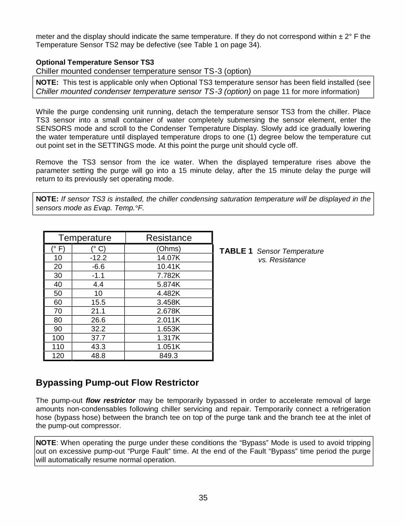
meter and the display should indicate the same temperature. If they do not correspond within ± 2° F the Temperature Sensor TS2 may be defective (see Table 1 on page 34). Optional Temperature Sensor TS3 Chiller mounted condenser temperature sensor TS-3 (option) NOTE: This test is applicable only when Optional TS3 temperature sensor has been field installed (see Chiller mounted condenser temperature sensor TS-3 (option) on page 11 for more information) While the purge condensing unit running, detach the temperature sensor TS3 from the chiller. Place TS3 sensor into a small container of water completely submersing the sensor element, enter the SENSORS mode and scroll to the Condenser Temperature Display. Slowly add ice gradually lowering the water temperature until displayed temperature drops to one (1) degree below the temperature cut out point set in the SETTINGS mode. At this point the purge unit should cycle off. Remove the TS3 sensor from the ice water. When the displayed temperature rises above the parameter setting the purge will go into a 15 minute delay, after the 15 minute delay the purge will return to its previously set operating mode. NOTE: If sensor TS3 is installed, the chiller condensing saturation temperature will be displayed in the sensors mode as Evap. Temp.°F.
TABLE 1 Sensor Temperature vs. Resistance
Bypassing Pump-out Flow Restrictor The pump-out flow restrictor may be temporarily bypassed in order to accelerate removal of large amounts non-condensables following chiller servicing and repair. Temporarily connect a refrigeration hose (bypass hose) between the branch tee on top of the purge tank and the branch tee at the inlet of the pump-out compressor.
NOTE: When operating the purge under these conditions the “Bypass” Mode is used to avoid tripping out on excessive pump-out “Purge Fault” time. At the end of the Fault “Bypass” time period the purge will automatically resume normal operation.
Temperature Resistance (° F) (° C) (Ohms) 10 -12.2 14.07K 20 -6.6 10.41K 30 -1.1 7.782K 40 4.4 5.874K 50 10 4.482K 60 15.5 3.458K 70 21.1 2.678K 80 26.6 2.011K 90 32.2 1.653K 100 37.7 1.317K 110 43.3 1.051K 120 48.8 849.3
36
NOTE: Pump-out time accumulated during "Fault Bypass" is not added to the 30-day averaging pumpout log. However, it is added to "Cumulative" pumpout time. NOTE: This is a manual procedure that will reduce the efficiency of the purge and should be used only during certain service conditions. NOTE: To minimize refrigerant loss; as soon as practical, the bypass hose should be removed and the purge returned to normal operation.
WARNING: DO NOT leave the purge unit unattended when operating in the Flow Restrictor Bypass mode. Leaving the purge unit unattended can result in loss of refrigerant.
37
Redi Controls Inc.
Limited Warranty Within one year from the date of purchase, REDI CONTROLS will, repair any REDI CONTROLS’ product being used by the original purchaser from the manufacturer, which is defective due to faulty materials or workmanship. REDI CONTROLS has the right to repair or replace a defective part or replace the entire product. To file a Warranty claim on any system or component, return the defective unit to Redi Controls as REDI CONTROLS directs, freight prepaid. This Warranty does not apply to or cover:
• Damages beyond REDI CONTROLS’ control.
• Malfunctions that result from failure to properly install, operate or maintain a product in accordance with instructions provided by REDI CONTROLS.
• Failures of equipment due to abuse, accident or negligence.
• Damages from, or part failures due to equipment not being installed per REDI CONTROLS’ instructions, per applicable codes or ordinances, or in accordance with good trade practices.
• Labor or other charges incurred in removing or reinstalling any REDI CONTROLS product or part.
• Damages resulting from use of a REDI CONTROLS product for any purpose other than for which it was designed and manufactured.
• Any implied warranty of merchantability or fitness for any particular purpose, occurring after the Warranty Period.
• Loss of use, loss of time, inconvenience, rental for substitute products, loss of business, loss of income, or any other consequential damages resulting from use or failure of any REDI CONTROLS product.
Inquiries to: REDI CONTROLS at 161 R J Parkway, Franklin, Indiana, 46131
REDI CONTROLS, INC. (317) 865-4130