Embed Size (px)
Citation preview
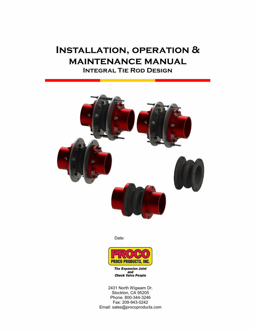
Date:
Installation, operation &
maintenance manual
Integral Tie Rod Design
2431 North Wigwam Dr. Stockton, CA 95205
Phone: 800-344-3246 Fax: 209-943-0242
Email: [email protected]
Proco Products, Inc. Page 1 2012 IOM Spool Type ITR
Table of Contents
1.0 Introduction ………………………………………………………… 2
2.0 Storage and Handling …………………………………………….. 2
3.0 Prior to Installation ...……….……………………………………… 3
4.0 Expansion Joint Installation .……………………………………… 6
5.0 System Testing .……………………………………………………. 12
6.0 Operating and Maintenance Procedures .……………………….. 12
7.0 Trouble Shooting .………………………………………………….. 14
APPENDIX A: Torque Data ……………………………………………. 15
APPENDIX B: Installation Record Sheet ……………………………... 17
Proco Products, Inc. Page 2 2012 IOM Spool Type ITR
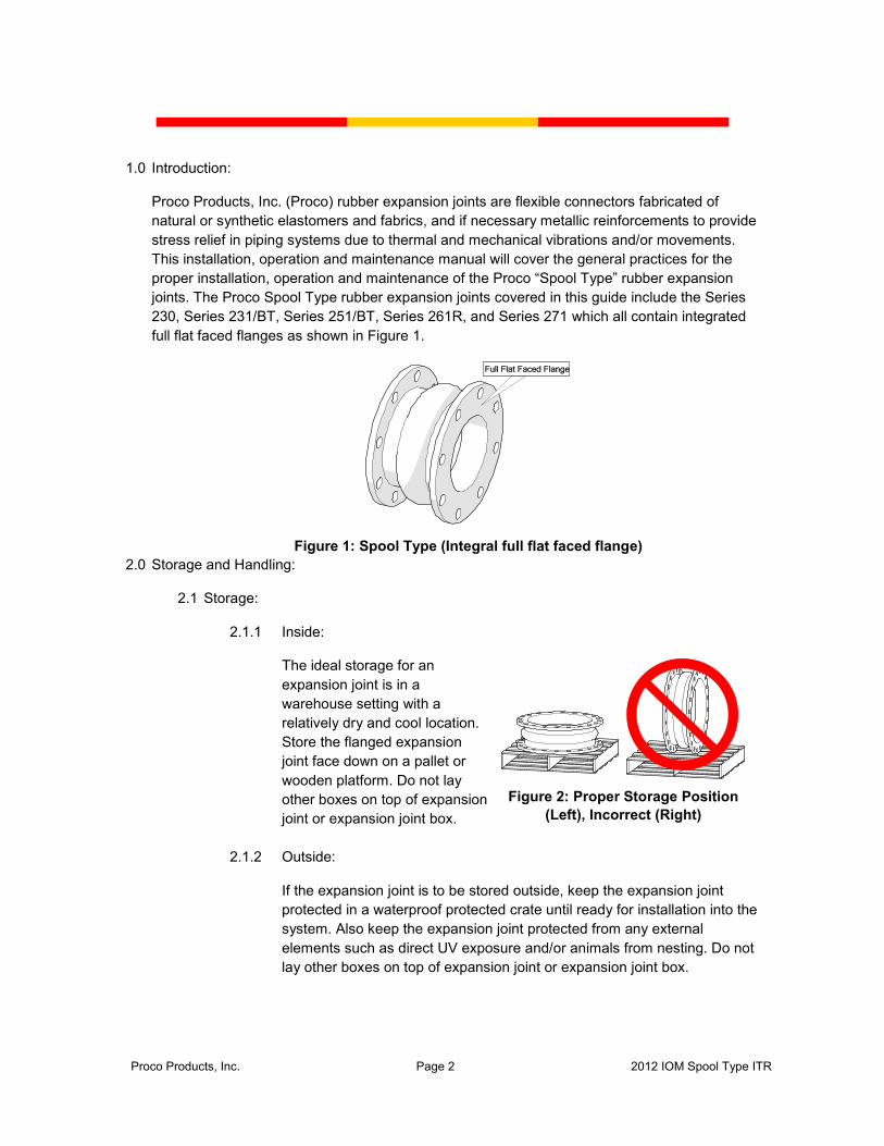
1.0 Introduction:
Proco Products, Inc. (Proco) rubber expansion joints are flexible connectors fabricated of
natural or synthetic elastomers and fabrics, and if necessary metallic reinforcements to provide
stress relief in piping systems due to thermal and mechanical vibrations and/or movements.
This installation, operation and maintenance manual will cover the general practices for the
proper installation, operation and maintenance of the Proco “Spool Type” rubber expansion
joints. The Proco Spool Type rubber expansion joints covered in this guide include the Series
230, Series 231/BT, Series 251/BT, Series 261R, and Series 271 which all contain integrated
full flat faced flanges as shown in Figure 1.
Figure 1: Spool Type (Integral full flat faced flange)
2.0 Storage and Handling:
2.1 Storage:
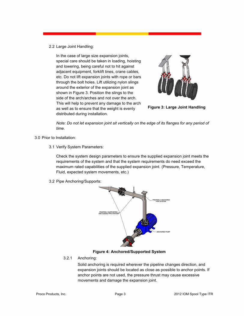
2.1.1 Inside:
The ideal storage for an
expansion joint is in a
warehouse setting with a
relatively dry and cool location.
Store the flanged expansion
joint face down on a pallet or
wooden platform. Do not lay
other boxes on top of expansion
joint or expansion joint box.
2.1.2 Outside:
If the expansion joint is to be stored outside, keep the expansion joint
protected in a waterproof protected crate until ready for installation into the
system. Also keep the expansion joint protected from any external
elements such as direct UV exposure and/or animals from nesting. Do not
lay other boxes on top of expansion joint or expansion joint box.
Figure 2: Proper Storage Position
(Left), Incorrect (Right)
Proco Products, Inc. Page 3 2012 IOM Spool Type ITR
2.2 Large Joint Handling:
In the case of large size expansion joints,
special care should be taken in loading, hoisting
and lowering, being careful not to hit against
adjacent equipment, forklift tines, crane cables,
etc. Do not lift expansion joints with rope or bars
through the bolt holes. Lift utilizing nylon slings
around the exterior of the expansion joint as
shown in Figure 3. Position the slings to the
side of the arch/arches and not over the arch.
This will help to prevent any damage to the arch
as well as to ensure that the weight is evenly
distributed during installation.
Note: Do not let expansion joint sit vertically on the edge of its flanges for any period of
time.
3.0 Prior to Installation:
3.1 Verify System Parameters:
Check the system design parameters to ensure the supplied expansion joint meets the
requirements of the system and that the system requirements do need exceed the
maximum rated capabilities of the supplied expansion joint. (Pressure, Temperature,
Fluid, expected system movements, etc.)
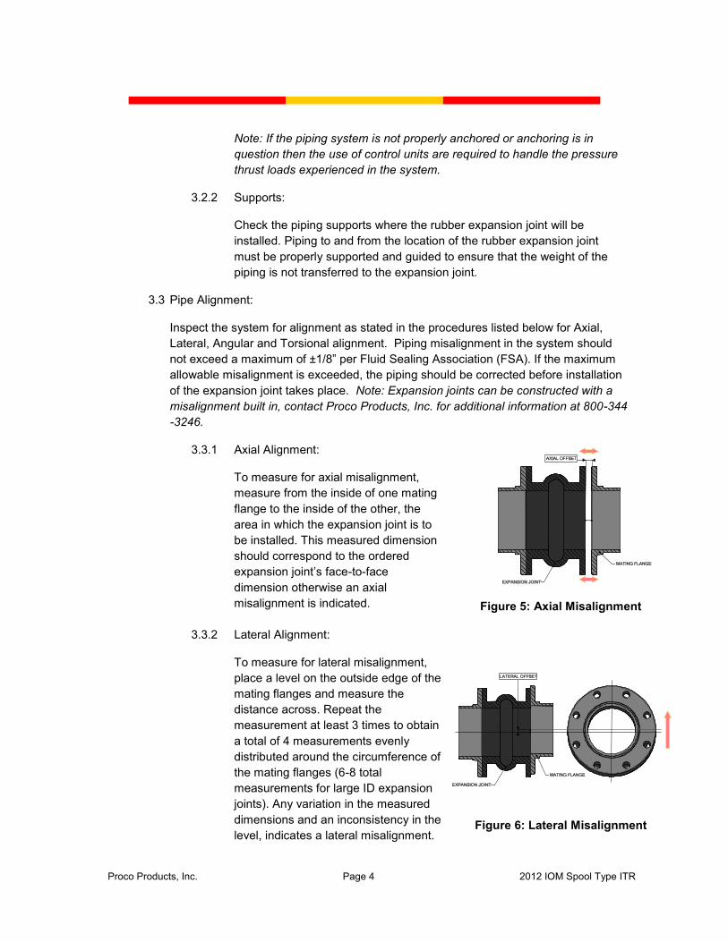
3.2 Pipe Anchoring/Supports:
Figure 4: Anchored/Supported System
3.2.1 Anchoring:
Solid anchoring is required wherever the pipeline changes direction, and
expansion joints should be located as close as possible to anchor points. If
anchor points are not used, the pressure thrust may cause excessive
movements and damage the expansion joint.
Figure 3: Large Joint Handling
Proco Products, Inc. Page 4 2012 IOM Spool Type ITR
Note: If the piping system is not properly anchored or anchoring is in
question then the use of control units are required to handle the pressure
thrust loads experienced in the system.
3.2.2 Supports:
Check the piping supports where the rubber expansion joint will be
installed. Piping to and from the location of the rubber expansion joint
must be properly supported and guided to ensure that the weight of the
piping is not transferred to the expansion joint.
3.3 Pipe Alignment:
Inspect the system for alignment as stated in the procedures listed below for Axial,
Lateral, Angular and Torsional alignment. Piping misalignment in the system should
not exceed a maximum of ±1/8” per Fluid Sealing Association (FSA). If the maximum
allowable misalignment is exceeded, the piping should be corrected before installation
of the expansion joint takes place. Note: Expansion joints can be constructed with a
misalignment built in, contact Proco Products, Inc. for additional information at 800-344
-3246.
3.3.1 Axial Alignment:
To measure for axial misalignment,
measure from the inside of one mating
flange to the inside of the other, the
area in which the expansion joint is to
be installed. This measured dimension
should correspond to the ordered
expansion joint’s face-to-face
dimension otherwise an axial
misalignment is indicated.
3.3.2 Lateral Alignment:
To measure for lateral misalignment,
place a level on the outside edge of the
mating flanges and measure the
distance across. Repeat the
measurement at least 3 times to obtain
a total of 4 measurements evenly
distributed around the circumference of
the mating flanges (6-8 total
measurements for large ID expansion
joints). Any variation in the measured
dimensions and an inconsistency in the
level, indicates a lateral misalignment.
Figure 5: Axial Misalignment
Figure 6: Lateral Misalignment
Proco Products, Inc. Page 5 2012 IOM Spool Type ITR
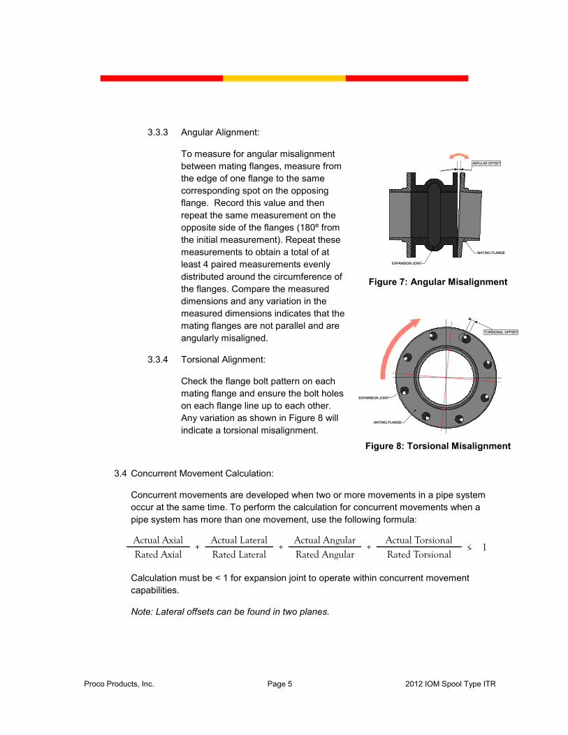
3.3.3 Angular Alignment:
To measure for angular misalignment
between mating flanges, measure from
the edge of one flange to the same
corresponding spot on the opposing
flange. Record this value and then
repeat the same measurement on the
opposite side of the flanges (180º from
the initial measurement). Repeat these
measurements to obtain a total of at
least 4 paired measurements evenly
distributed around the circumference of
the flanges. Compare the measured
dimensions and any variation in the
measured dimensions indicates that the
mating flanges are not parallel and are
angularly misaligned.
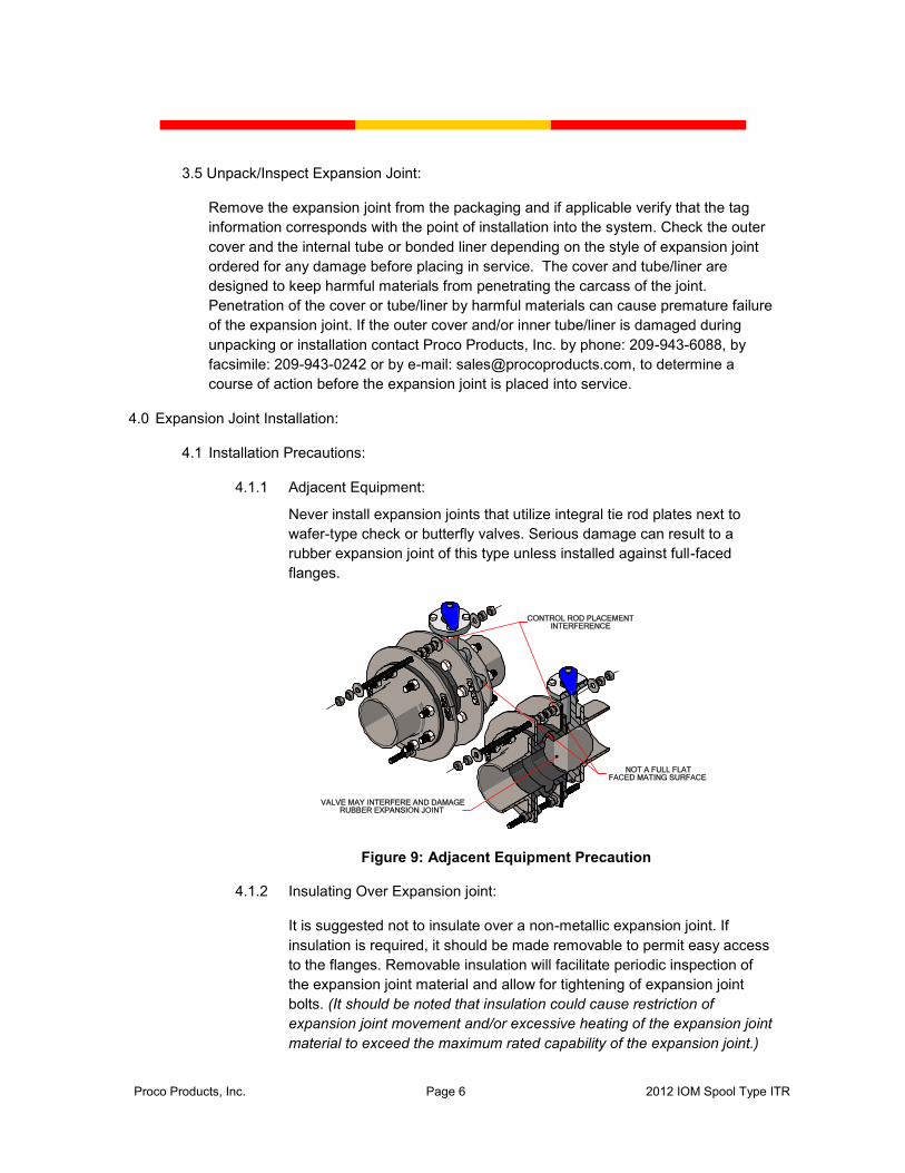
3.3.4 Torsional Alignment:
Check the flange bolt pattern on each
mating flange and ensure the bolt holes
on each flange line up to each other.
Any variation as shown in Figure 8 will
indicate a torsional misalignment.
3.4 Concurrent Movement Calculation:
Concurrent movements are developed when two or more movements in a pipe system
occur at the same time. To perform the calculation for concurrent movements when a
pipe system has more than one movement, use the following formula:
Calculation must be < 1 for expansion joint to operate within concurrent movement
capabilities.
Note: Lateral offsets can be found in two planes.
Figure 8: Torsional Misalignment
Figure 7: Angular Misalignment
Actual Axial +
Actual Lateral +
Actual Angular +
Actual Torsional ≤ 1
Rated Axial Rated Lateral Rated Angular Rated Torsional
Proco Products, Inc. Page 6 2012 IOM Spool Type ITR
3.5 Unpack/Inspect Expansion Joint:
Remove the expansion joint from the packaging and if applicable verify that the tag
information corresponds with the point of installation into the system. Check the outer
cover and the internal tube or bonded liner depending on the style of expansion joint
ordered for any damage before placing in service. The cover and tube/liner are
designed to keep harmful materials from penetrating the carcass of the joint.
Penetration of the cover or tube/liner by harmful materials can cause premature failure
of the expansion joint. If the outer cover and/or inner tube/liner is damaged during
unpacking or installation contact Proco Products, Inc. by phone: 209-943-6088, by
facsimile: 209-943-0242 or by e-mail: [email protected], to determine a
course of action before the expansion joint is placed into service.
4.0 Expansion Joint Installation:
4.1 Installation Precautions:
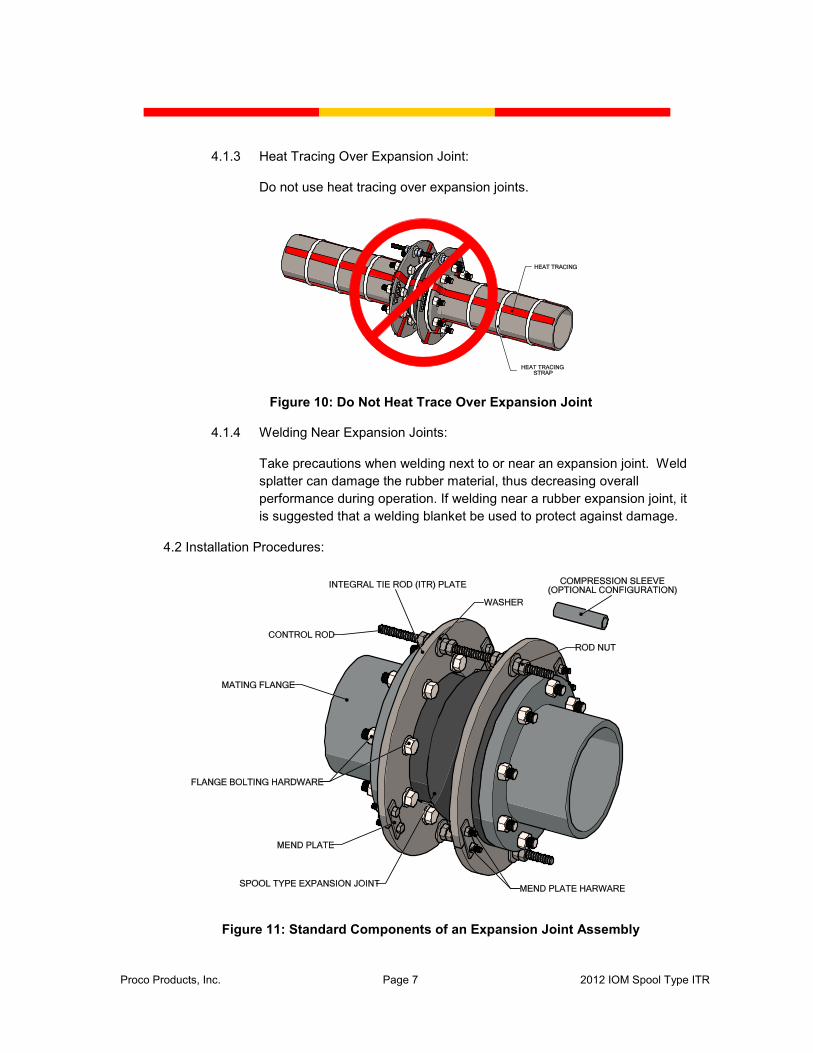
4.1.1 Adjacent Equipment:
Never install expansion joints that utilize integral tie rod plates next to
wafer-type check or butterfly valves. Serious damage can result to a
rubber expansion joint of this type unless installed against full-faced
flanges.
Figure 9: Adjacent Equipment Precaution
4.1.2 Insulating Over Expansion joint:
It is suggested not to insulate over a non-metallic expansion joint. If
insulation is required, it should be made removable to permit easy access
to the flanges. Removable insulation will facilitate periodic inspection of
the expansion joint material and allow for tightening of expansion joint
bolts. (It should be noted that insulation could cause restriction of
expansion joint movement and/or excessive heating of the expansion joint
material to exceed the maximum rated capability of the expansion joint.)
Proco Products, Inc. Page 7 2012 IOM Spool Type ITR
4.1.3 Heat Tracing Over Expansion Joint:
Do not use heat tracing over expansion joints.
Figure 10: Do Not Heat Trace Over Expansion Joint
4.1.4 Welding Near Expansion Joints:
Take precautions when welding next to or near an expansion joint. Weld
splatter can damage the rubber material, thus decreasing overall
performance during operation. If welding near a rubber expansion joint, it
is suggested that a welding blanket be used to protect against damage.
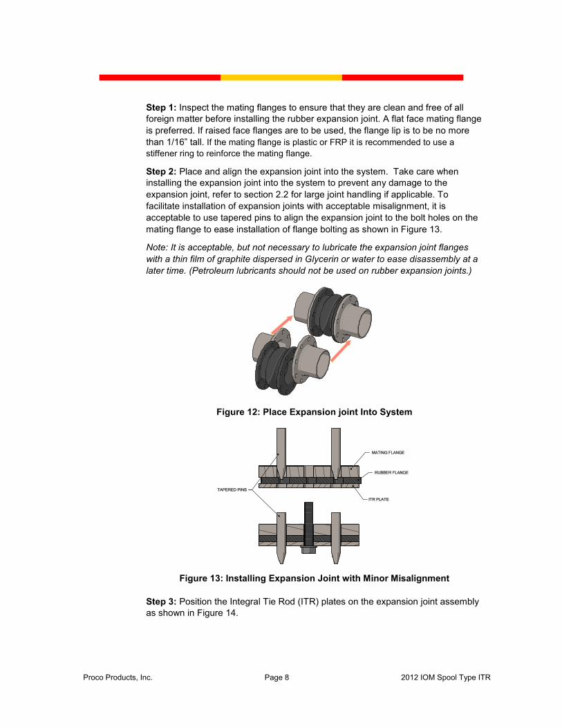
4.2 Installation Procedures:
Figure 11: Standard Components of an Expansion Joint Assembly
Proco Products, Inc. Page 8 2012 IOM Spool Type ITR
Step 1: Inspect the mating flanges to ensure that they are clean and free of all
foreign matter before installing the rubber expansion joint. A flat face mating flange
is preferred. If raised face flanges are to be used, the flange lip is to be no more
than 1/16” tall. If the mating flange is plastic or FRP it is recommended to use a
stiffener ring to reinforce the mating flange.
Step 2: Place and align the expansion joint into the system. Take care when
installing the expansion joint into the system to prevent any damage to the
expansion joint, refer to section 2.2 for large joint handling if applicable. To
facilitate installation of expansion joints with acceptable misalignment, it is
acceptable to use tapered pins to align the expansion joint to the bolt holes on the
mating flange to ease installation of flange bolting as shown in Figure 13.
Note: It is acceptable, but not necessary to lubricate the expansion joint flanges
with a thin film of graphite dispersed in Glycerin or water to ease disassembly at a
later time. (Petroleum lubricants should not be used on rubber expansion joints.)
Figure 12: Place Expansion joint Into System
Figure 13: Installing Expansion Joint with Minor Misalignment
Step 3: Position the Integral Tie Rod (ITR) plates on the expansion joint assembly
as shown in Figure 14.
Proco Products, Inc. Page 9 2012 IOM Spool Type ITR
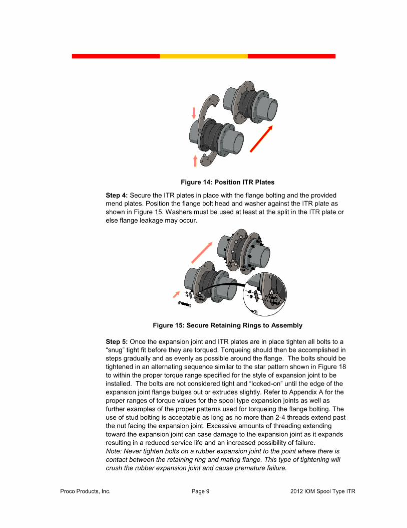
Figure 14: Position ITR Plates
Step 4: Secure the ITR plates in place with the flange bolting and the provided
mend plates. Position the flange bolt head and washer against the ITR plate as
shown in Figure 15. Washers must be used at least at the split in the ITR plate or
else flange leakage may occur.
Figure 15: Secure Retaining Rings to Assembly
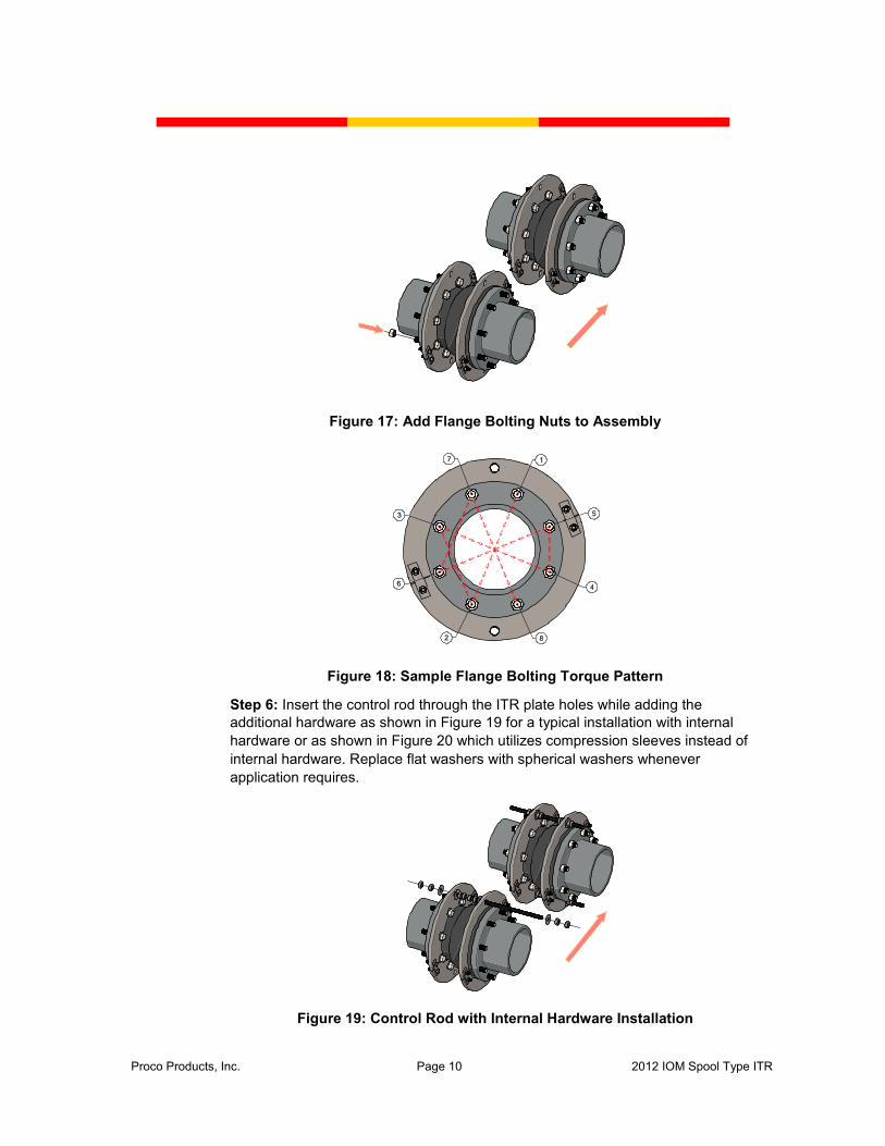
Step 5: Once the expansion joint and ITR plates are in place tighten all bolts to a
“snug” tight fit before they are torqued. Torqueing should then be accomplished in
steps gradually and as evenly as possible around the flange. The bolts should be
tightened in an alternating sequence similar to the star pattern shown in Figure 18
to within the proper torque range specified for the style of expansion joint to be
installed. The bolts are not considered tight and “locked-on” until the edge of the
expansion joint flange bulges out or extrudes slightly. Refer to Appendix A for the
proper ranges of torque values for the spool type expansion joints as well as
further examples of the proper patterns used for torqueing the flange bolting. The
use of stud bolting is acceptable as long as no more than 2-4 threads extend past
the nut facing the expansion joint. Excessive amounts of threading extending
toward the expansion joint can case damage to the expansion joint as it expands
resulting in a reduced service life and an increased possibility of failure.
Note: Never tighten bolts on a rubber expansion joint to the point where there is
contact between the retaining ring and mating flange. This type of tightening will
crush the rubber expansion joint and cause premature failure.
Proco Products, Inc. Page 10 2012 IOM Spool Type ITR
Figure 17: Add Flange Bolting Nuts to Assembly
Figure 18: Sample Flange Bolting Torque Pattern
Step 6: Insert the control rod through the ITR plate holes while adding the
additional hardware as shown in Figure 19 for a typical installation with internal
hardware or as shown in Figure 20 which utilizes compression sleeves instead of
internal hardware. Replace flat washers with spherical washers whenever
application requires.
Figure 19: Control Rod with Internal Hardware Installation
Proco Products, Inc. Page 11 2012 IOM Spool Type ITR
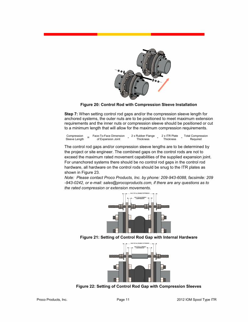
Figure 20: Control Rod with Compression Sleeve Installation
Step 7: When setting control rod gaps and/or the compression sleeve length for anchored systems, the outer nuts are to be positioned to meet maximum extension requirements and the inner nuts or compression sleeve should be positioned or cut to a minimum length that will allow for the maximum compression requirements.
The control rod gaps and/or compression sleeve lengths are to be determined by
the project or site engineer. The combined gaps on the control rods are not to
exceed the maximum rated movement capabilities of the supplied expansion joint.
For unanchored systems there should be no control rod gaps in the control rod
hardware, all hardware on the control rods should be snug to the ITR plates as
shown in Figure 23.
Note: Please contact Proco Products, Inc. by phone: 209-943-6088, facsimile: 209
-943-0242, or e-mail: [email protected], if there are any questions as to
the rated compression or extension movements.
Figure 21: Setting of Control Rod Gap with Internal Hardware
Figure 22: Setting of Control Rod Gap with Compression Sleeves
Compression Sleeve Length
= Face-To-Face Dimension
of Expansion Joint -
2 x Rubber Flange Thickness
- 2 x ITR Plate
Thickness -
Total Compression Required
Proco Products, Inc. Page 12 2012 IOM Spool Type ITR
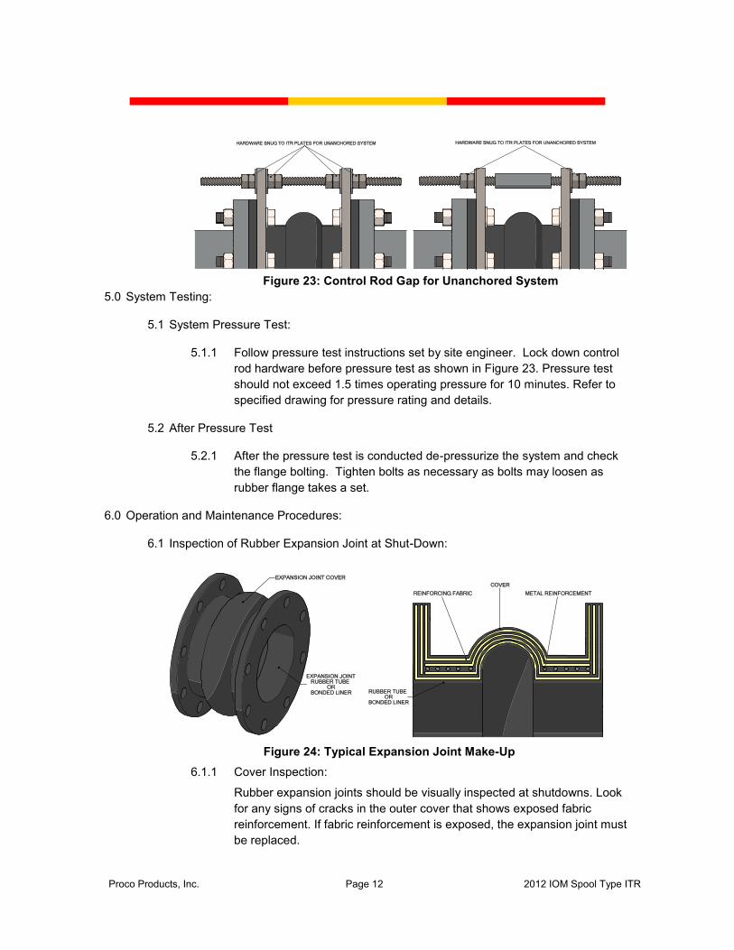
Figure 23: Control Rod Gap for Unanchored System
5.0 System Testing:
5.1 System Pressure Test:
5.1.1 Follow pressure test instructions set by site engineer. Lock down control
rod hardware before pressure test as shown in Figure 23. Pressure test
should not exceed 1.5 times operating pressure for 10 minutes. Refer to
specified drawing for pressure rating and details.
5.2 After Pressure Test
5.2.1 After the pressure test is conducted de-pressurize the system and check
the flange bolting. Tighten bolts as necessary as bolts may loosen as
rubber flange takes a set.
6.0 Operation and Maintenance Procedures:
6.1 Inspection of Rubber Expansion Joint at Shut-Down:
Figure 24: Typical Expansion Joint Make-Up
6.1.1 Cover Inspection:
Rubber expansion joints should be visually inspected at shutdowns. Look
for any signs of cracks in the outer cover that shows exposed fabric
reinforcement. If fabric reinforcement is exposed, the expansion joint must
be replaced.
Proco Products, Inc. Page 13 2012 IOM Spool Type ITR
6.1.2 Tube/Liner Inspection:
If inspection of the internal rubber tube or bonded liner of the expansion
joint is possible look for signs of exposed fabric, excessive wear or
cracking. If the inner tube or bonded liner show any of these signs, the
expansion joint must be replaced.
6.2 Expansion Joint Bolt Check:
Check expansion joint at least one week after start-up to ensure that bolts are tight on
expansion joint and the ITR assembly. As any rubber-like material takes a “set” after a
period of compression, bolts may loosen; thus resulting in a possible broken seal
between the expansion joint and the mating flange. Periodically check bolting to
ensure bolts are tight. Tighten as necessary.
Note: Ensure system is de-pressurized before tightening flange bolting.
6.3 Service Conditions:
Make sure the expansion joint operates at the temperature, pressure, vacuum, and
movements matching the original requirements. Contact Proco’s Customer Service
Department by phone: 209-943-6088, facsimile: 209-943-2042, or e-mail:
[email protected], if the system requirements exceed those specified.
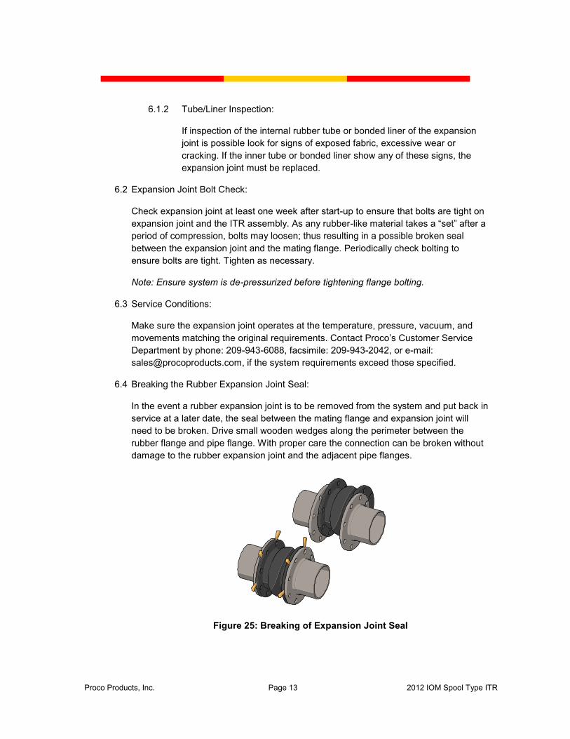
6.4 Breaking the Rubber Expansion Joint Seal:
In the event a rubber expansion joint is to be removed from the system and put back in
service at a later date, the seal between the mating flange and expansion joint will
need to be broken. Drive small wooden wedges along the perimeter between the
rubber flange and pipe flange. With proper care the connection can be broken without
damage to the rubber expansion joint and the adjacent pipe flanges.
Figure 25: Breaking of Expansion Joint Seal
Proco Products, Inc. Page 14 2012 IOM Spool Type ITR
6.5 Spares:
A rubber expansion joint spare should be put in stock in the event a mechanical failure
occurs. Stock one (1) spare for each size purchased. Although these expansion joints
are engineered to give long, dependable service, the cost of equipment downtime, in
the event of a mechanical failure, can far outweigh the cost of a spare. Spares will be
packaged in waterproof crates and prepared for storage.
7.0 Trouble Shooting
7.1 Leaking at the Flange:
7.1.1 The flange bolts may need retightening. On the rubber expansion joints
the flange bolting should be tight enough to make the edge of the rubber
flange bulge slightly between the metal flange and the retaining rings.
Ensure system is depressurized before tightening the flange bolting.
7.1.2 The surface of the mating flange may be in poor condition. Make sure
there are no excessive grooves, scratches or distorted areas.
7.1.3 The joint may have been over-extended to such an extent that it has
caused the rubber flange to pull away from the mating flange. If so, verify
that the control unit was properly installed and an appropriate control rod
gap was set.
7.2 Cracking at Base of Arch or Flange:
Make sure the installed face-to-face dimension is correct so that the joint is not over-
extended or over-compressed. Check to see if the pipes are properly aligned so there
is no excessive misalignment. Pipes should not be more than1/8” out of alignment.
Check to see if system is properly anchored or if control rods are used. External
cracking of cover does not mean failure. This is often caused by exposure to strong
sunlight in an extended condition. If cracking extends to the fabric reinforcing member,
the expansion joint must be replaced.
7.3 Liquid Weeping through Bolt Holes:
Look for a break in the tube portion of the joint. If there is a crack or a break, the joint
must be replaced as soon as possible.
7.4 Excessive Ballooning of Arch:
Ballooning is usually an indication of deterioration of the joint’s strengthening members
or excessive pressure in the system. Service conditions should be double-checked
and a new joint must be installed.
Proco Products, Inc. Page 15 2012 IOM Spool Type ITR
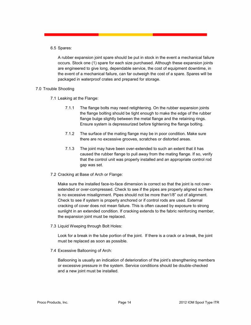
APPENDIX A: Torque Data
Table 1: Spool Type Torque Values
Size Approx. Torque Values
1" thru 2" 20 - 40 ft./lbs.
2.5" thru 5" 25 - 60 ft./lbs.
6" thru 12" 35 - 140 ft./lbs.
14" thru 18" 50 - 180 ft./lbs.
20" thru 24" 60 - 200 ft./lbs.
26" thru 40" 70 - 300 ft./lbs.
42" thru 50" 80 - 300 ft./lbs.
52" thru 60" 100 - 400 ft./lbs.
66" thru 72" 200 - 500 ft./lbs.
78" thru 90" 300 - 600 ft./lbs.
96" thru 108" 400 - 700 ft./lbs.
120" 500 - 800 ft./lbs.
Proco Products, Inc. Page 16 2012 IOM Spool Type ITR
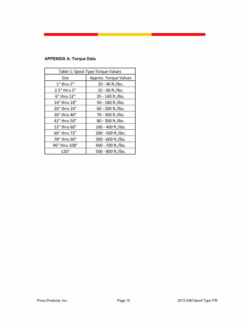
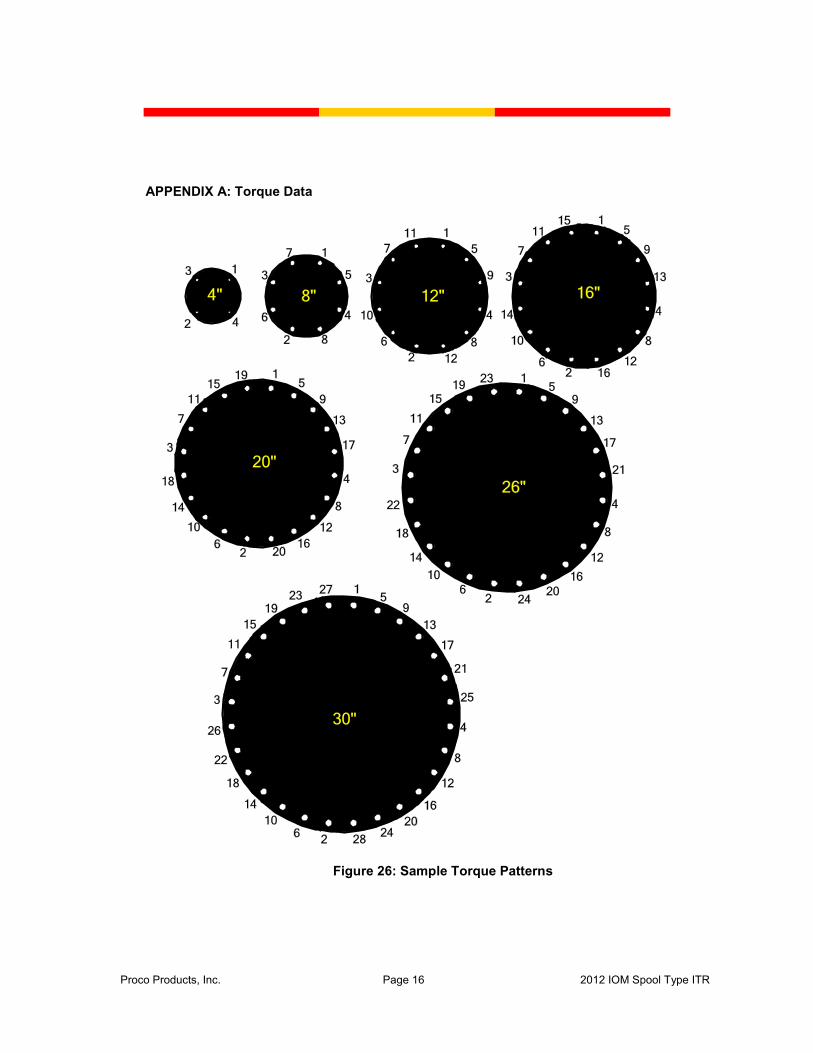
APPENDIX A: Torque Data
Figure 26: Sample Torque Patterns
Proco Products, Inc. Page 17 2012 IOM Spool Type ITR
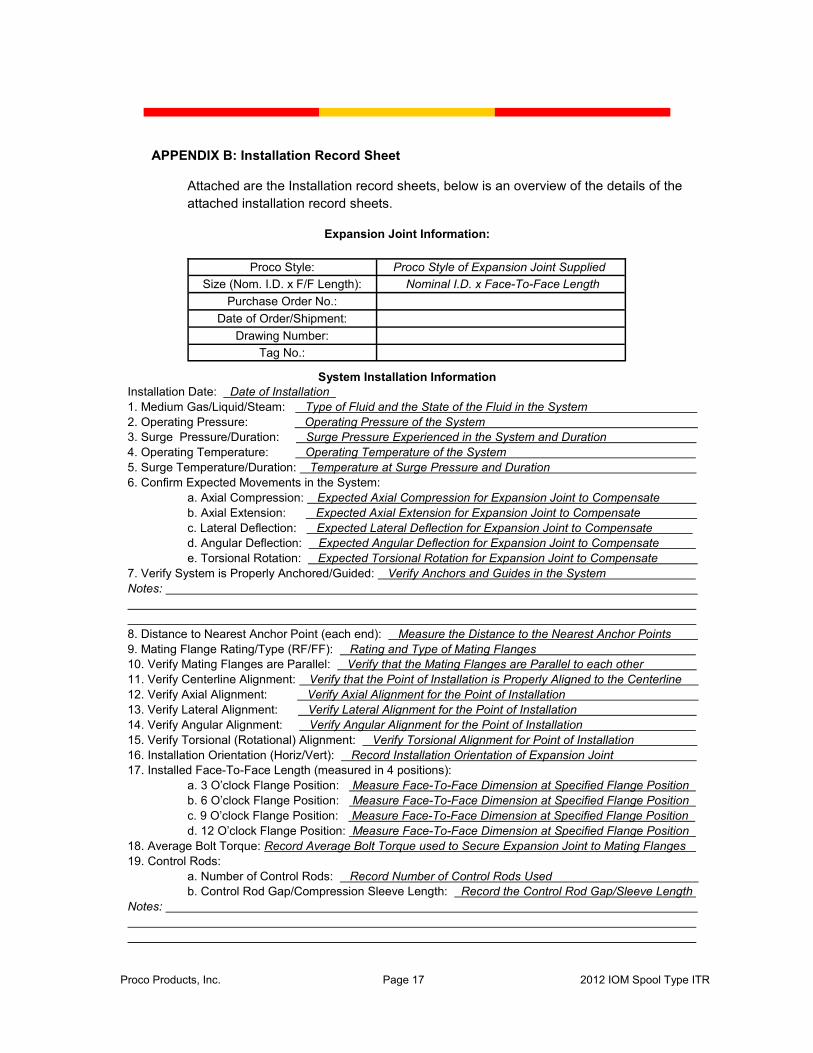
APPENDIX B: Installation Record Sheet
Attached are the Installation record sheets, below is an overview of the details of the
attached installation record sheets.
Expansion Joint Information:
System Installation Information
Installation Date: Date of Installation
1. Medium Gas/Liquid/Steam: Type of Fluid and the State of the Fluid in the System
2. Operating Pressure: Operating Pressure of the System
3. Surge Pressure/Duration: Surge Pressure Experienced in the System and Duration
4. Operating Temperature: Operating Temperature of the System
5. Surge Temperature/Duration: Temperature at Surge Pressure and Duration
6. Confirm Expected Movements in the System:
a. Axial Compression: Expected Axial Compression for Expansion Joint to Compensate
b. Axial Extension: Expected Axial Extension for Expansion Joint to Compensate
c. Lateral Deflection: Expected Lateral Deflection for Expansion Joint to Compensate
d. Angular Deflection: Expected Angular Deflection for Expansion Joint to Compensate
e. Torsional Rotation: Expected Torsional Rotation for Expansion Joint to Compensate
7. Verify System is Properly Anchored/Guided: Verify Anchors and Guides in the System
Notes:
8. Distance to Nearest Anchor Point (each end): Measure the Distance to the Nearest Anchor Points
9. Mating Flange Rating/Type (RF/FF): Rating and Type of Mating Flanges
10. Verify Mating Flanges are Parallel: Verify that the Mating Flanges are Parallel to each other
11. Verify Centerline Alignment: Verify that the Point of Installation is Properly Aligned to the Centerline
12. Verify Axial Alignment: Verify Axial Alignment for the Point of Installation
13. Verify Lateral Alignment: Verify Lateral Alignment for the Point of Installation
14. Verify Angular Alignment: Verify Angular Alignment for the Point of Installation
15. Verify Torsional (Rotational) Alignment: Verify Torsional Alignment for Point of Installation
16. Installation Orientation (Horiz/Vert): Record Installation Orientation of Expansion Joint
17. Installed Face-To-Face Length (measured in 4 positions):
a. 3 O’clock Flange Position: Measure Face-To-Face Dimension at Specified Flange Position
b. 6 O’clock Flange Position: Measure Face-To-Face Dimension at Specified Flange Position
c. 9 O’clock Flange Position: Measure Face-To-Face Dimension at Specified Flange Position
d. 12 O’clock Flange Position: Measure Face-To-Face Dimension at Specified Flange Position
18. Average Bolt Torque: Record Average Bolt Torque used to Secure Expansion Joint to Mating Flanges
19. Control Rods:
a. Number of Control Rods: Record Number of Control Rods Used
b. Control Rod Gap/Compression Sleeve Length: Record the Control Rod Gap/Sleeve Length
Notes:
Proco Style: Proco Style of Expansion Joint Supplied Size (Nom. I.D. x F/F Length): Nominal I.D. x Face-To-Face Length
Purchase Order No.: Date of Order/Shipment:
Drawing Number: Tag No.:
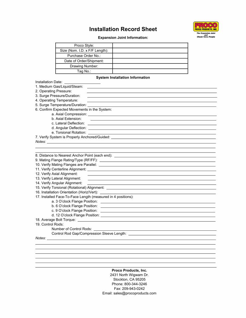
Installation Record Sheet
Expansion Joint Information:
System Installation Information
Installation Date:
1. Medium Gas/Liquid/Steam:
2. Operating Pressure:
3. Surge Pressure/Duration:
4. Operating Temperature:
5. Surge Temperature/Duration:
6. Confirm Expected Movements in the System:
a. Axial Compression:
b. Axial Extension:
c. Lateral Deflection:
d. Angular Deflection:
e. Torsional Rotation:
7. Verify System is Properly Anchored/Guided:
Notes:
8. Distance to Nearest Anchor Point (each end):
9. Mating Flange Rating/Type (RF/FF):
10. Verify Mating Flanges are Parallel:
11. Verify Centerline Alignment:
12. Verify Axial Alignment:
13. Verify Lateral Alignment:
14. Verify Angular Alignment:
15. Verify Torsional (Rotational) Alignment:
16. Installation Orientation (Horiz/Vert):
17. Installed Face-To-Face Length (measured in 4 positions):
a. 3 O’clock Flange Position:
b. 6 O’clock Flange Position:
c. 9 O’clock Flange Position:
d. 12 O’clock Flange Position:
18. Average Bolt Torque:
19. Control Rods:
Number of Control Rods:
Control Rod Gap/Compression Sleeve Length:
Notes:
Proco Products, Inc.
2431 North Wigwam Dr.
Stockton, CA 95205
Phone: 800-344-3246
Fax: 209-943-0242
Email: [email protected]
Proco Style: Size (Nom. I.D. x F/F Length):
Purchase Order No.: Date of Order/Shipment:
Drawing Number: Tag No.: