Embed Size (px)
Citation preview

INSTALLATION OPERATION
MAINTENANCE MANUAL
CLOSED LOOP PV
Alternate Energy Technologies, LLC. PO Box 61326
Jacksonville, Florida 32236 904-781-8305
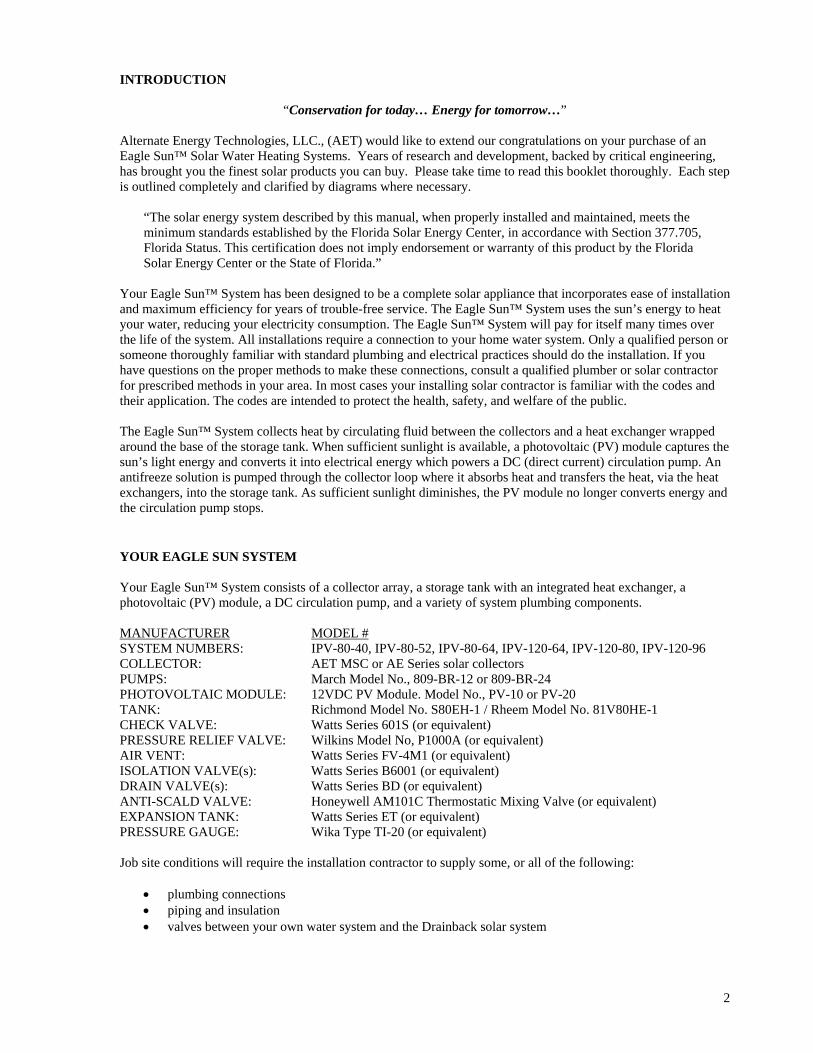
INTRODUCTION
“Conservation for today… Energy for tomorrow…” Alternate Energy Technologies, LLC., (AET) would like to extend our congratulations on your purchase of an Eagle Sun™ Solar Water Heating Systems. Years of research and development, backed by critical engineering, has brought you the finest solar products you can buy. Please take time to read this booklet thoroughly. Each step is outlined completely and clarified by diagrams where necessary.
“The solar energy system described by this manual, when properly installed and maintained, meets the minimum standards established by the Florida Solar Energy Center, in accordance with Section 377.705, Florida Status. This certification does not imply endorsement or warranty of this product by the Florida Solar Energy Center or the State of Florida.”
Your Eagle Sun™ System has been designed to be a complete solar appliance that incorporates ease of installation and maximum efficiency for years of trouble-free service. The Eagle Sun™ System uses the sun’s energy to heat your water, reducing your electricity consumption. The Eagle Sun™ System will pay for itself many times over the life of the system. All installations require a connection to your home water system. Only a qualified person or someone thoroughly familiar with standard plumbing and electrical practices should do the installation. If you have questions on the proper methods to make these connections, consult a qualified plumber or solar contractor for prescribed methods in your area. In most cases your installing solar contractor is familiar with the codes and their application. The codes are intended to protect the health, safety, and welfare of the public. The Eagle Sun™ System collects heat by circulating fluid between the collectors and a heat exchanger wrapped around the base of the storage tank. When sufficient sunlight is available, a photovoltaic (PV) module captures the sun’s light energy and converts it into electrical energy which powers a DC (direct current) circulation pump. An antifreeze solution is pumped through the collector loop where it absorbs heat and transfers the heat, via the heat exchangers, into the storage tank. As sufficient sunlight diminishes, the PV module no longer converts energy and the circulation pump stops. YOUR EAGLE SUN SYSTEM Your Eagle Sun™ System consists of a collector array, a storage tank with an integrated heat exchanger, a photovoltaic (PV) module, a DC circulation pump, and a variety of system plumbing components. MANUFACTURER MODEL # SYSTEM NUMBERS: IPV-80-40, IPV-80-52, IPV-80-64, IPV-120-64, IPV-120-80, IPV-120-96 COLLECTOR: AET MSC or AE Series solar collectors PUMPS: March Model No., 809-BR-12 or 809-BR-24 PHOTOVOLTAIC MODULE: 12VDC PV Module. Model No., PV-10 or PV-20 TANK: Richmond Model No. S80EH-1 / Rheem Model No. 81V80HE-1 CHECK VALVE: Watts Series 601S (or equivalent) PRESSURE RELIEF VALVE: Wilkins Model No, P1000A (or equivalent) AIR VENT: Watts Series FV-4M1 (or equivalent) ISOLATION VALVE(s): Watts Series B6001 (or equivalent) DRAIN VALVE(s): Watts Series BD (or equivalent) ANTI-SCALD VALVE: Honeywell AM101C Thermostatic Mixing Valve (or equivalent) EXPANSION TANK: Watts Series ET (or equivalent) PRESSURE GAUGE: Wika Type TI-20 (or equivalent) Job site conditions will require the installation contractor to supply some, or all of the following:
• plumbing connections • piping and insulation • valves between your own water system and the Drainback solar system
2
INSTALLATION INSTRUCTIONS
3
4
PRE-INSTALLATION CHECKLIST Unlike other types of solar collectors, the AET solar collectors do not add a significant amount of weight to the roof. However, if the collectors are placed at a steeper pitch than the roof itself, the additional exposed flat surfaces could present extreme wind loading forces during sustained high winds. Check local codes for roof load requirements. The mounting hardware supplied with your Eagle Sun™ System has been designed for specific wind loads, but only if adequate support structure is present with sufficiently strong structural members (such as engineered trusses). Most building permit offices may be able to help you with recommended roofing practices for your area.
Obtain all applicable permits. Structural members penetrated by the solar system components must meet local codes. The installer is to run the piping in such a way that the performance of any fire rated assembly is not reduced. This applies to the collector mounting as well as the installation of any other system components. Inspect the roof. If it is in poor condition, it is advisable to replace all or part of the roof where the system will be attached. Locate a roof area facing as close to due south as possible for the placement of the solar collectors. The plumbing runs must be planned in advance so that the shortest possible route between the storage tank and collector is made. Make sure you have no low points in the sloped horizontal pipe runs. Sloping the feed/return piping ¼” per foot will insure the system drains fully if required. Make sure you have all the necessary plumbing materials, tools, and accessories before beginning work. Wear gloves when handling the solar collectors! They get extremely hot when left exposed to the sun. The bright orange plastic caps should be removed prior to placing the collectors on the roof otherwise they may get so hot that they melt in place. Also, never try to lift the collectors by the pipe nipples. These bend when hot and would damage the collector. You should have a tarp handy to keep the collectors covered during the entire installation process. This will prevent the collectors becoming too hot to handle as you make your final adjustments and connections. Use only lead-free solder. Use of 50/50 lead solder is expressly prohibited. Use of galvanized steel, CPVC, PVC, PEX or any other type of plastic pipe is prohibited. BASIC TOOLS AND MATERIALS Electric Drill Drill Index (w/ ½” and ¾” Wood Bits) Hack Saw Tubing Cutter Tin Snips 16’ Tape Measure 24” Level Flashlight Extension Cord Slip Joint Pliers Needle Nose Pliers Pipe Wretches, 10” & 14” Open End Wrenches, 9/16 & 7/16 Screw Driver 6” Flat Blade Screw Driver 6” Philips Wire Stripper or Knife Wire Cutters Adjustable Wrenches 8”& 10
Torch and Striker Putty Knife High Temperature Pipe Joint Compound Wire Nuts or Connectors Miscellaneous Copper Pipe & Fittings (3/4”) Solder Flux Emory Paper Silicon Caulk and Roof Tar ½” I.D. and ¾” I.D. Type M Copper Tubing 5/8” x ½” wall & 7/8” x ½” wall Armaflex or Rubatex Insulation Angle Iron Threaded Rod, Nuts, & Washers Stainless Screw Clamps Thermal Adhesive Aluminum Flashing Sheet Black Latex Outdoor Paint
INSTALLATION The Eagle Sun™ storage tank module is as easy to install as any normal electric hot water heater. Any experienced plumber or solar contractor may accomplish this installation. In addition to the normal cold water in, and hot water out connections, there are only two other connections required. Dielectric nipples must be used on all connections to the tank. These are used wherever copper and galvanized lines are connected together. This is a requirement of the Uniform Plumbing Code. Typically, galvanized pipe nipples are used for all connections into the tank, which has ferrous female standard pipe thread, 3/4" nominal (3/4" inside diameter). One side of a dielectric union fits a standard galvanized pipe nipple, and the other side is brass or bronze for soldering to a copper pipe. With solar tanks, the cold input from the pressurized supply line to the house (either city water or well water) must be fed into the tank inlet. This is marked "Cold Inlet" and is located on top of the tank. There is a long plastic tube attached internally to this connection so that incoming cold water is directed immediately to the bottom of the tank, and therefore does not mix and cool down the hot water. A cold-water shutoff valve must be installed above this connection so that water flow may be completely stopped in the event of a leak, repair, or maintenance. The hot water output to the house from the tank should be connected to the port labeled "Hot Outlet" on the top of the tank. Again, a dielectric union must be used where a connection is made between galvanized and copper pipes. A mixing valve may be installed at this point to limit the temperature of water delivered to the home. All plumbing lines should be insulated with at least 1/2" thick heat resistant rubber tubing insulation such as Armstrong Armaflex. In most instances, the solar collectors can be attached to the roof using the standard mounting hardware provided with the Eagle Sun™ System. Certain types of roofing will require special attention for proper mounting. For example, a clay tile or cement tile roof. Complete roofing attachment methods of solar collectors for these various types of roofs are beyond the scope of this manual. The manual will describe and illustrate some of these approved mounting techniques. A competent contractor should be used to ensure that all roof penetrations and attachment points are not a source of rainwater leakage later on. Standard plumbing roof jacks or solar industry copper flashings may be used for plumbing penetrations in most cases.
CAUTION! Solar collectors become very hot when in direct sunlight with no fluid being circulated through them.
Extreme caution should be taken when standing near, or handling solar collectors in this state. The circulating pump becomes very hot when running. Do not touch before allowing sufficient time to cool down.
COLLECTOR LOCATION
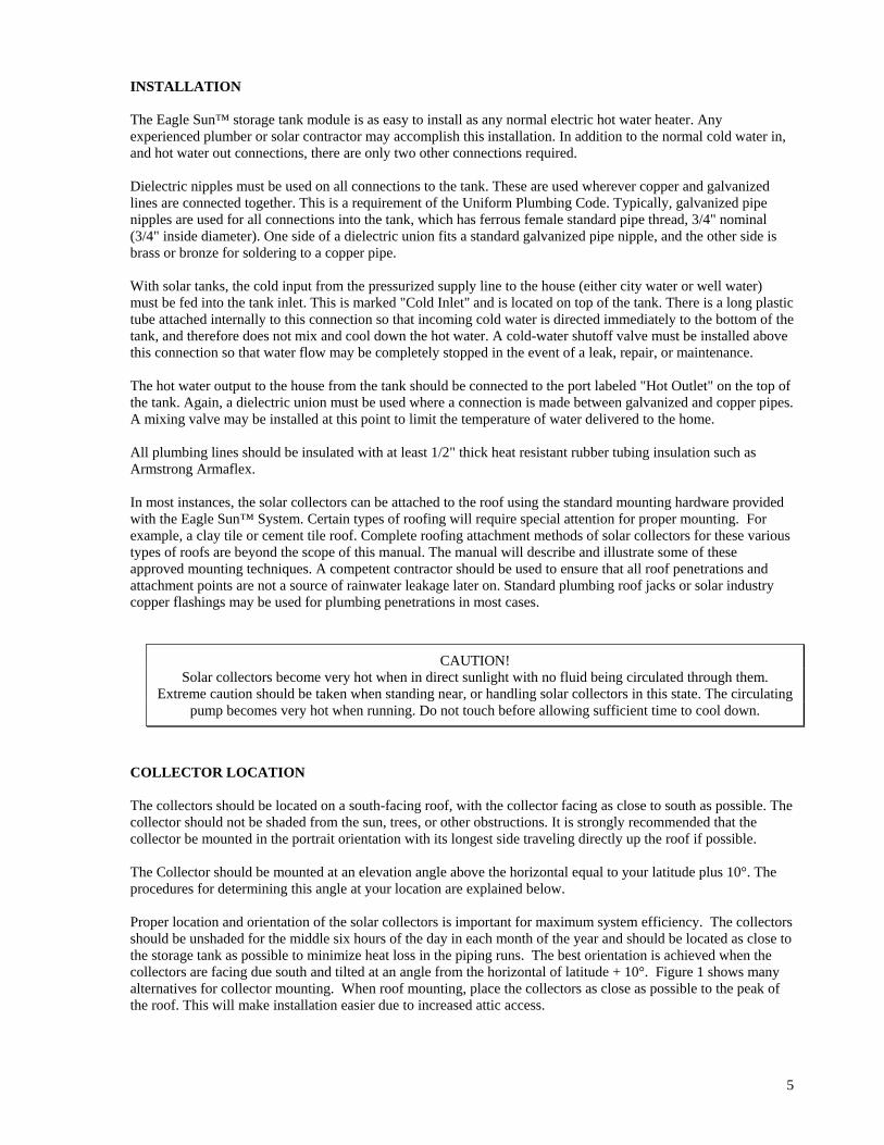
The collectors should be located on a south-facing roof, with the collector facing as close to south as possible. The collector should not be shaded from the sun, trees, or other obstructions. It is strongly recommended that the collector be mounted in the portrait orientation with its longest side traveling directly up the roof if possible. The Collector should be mounted at an elevation angle above the horizontal equal to your latitude plus 10°. The procedures for determining this angle at your location are explained below. Proper location and orientation of the solar collectors is important for maximum system efficiency. The collectors should be unshaded for the middle six hours of the day in each month of the year and should be located as close to the storage tank as possible to minimize heat loss in the piping runs. The best orientation is achieved when the collectors are facing due south and tilted at an angle from the horizontal of latitude + 10°. Figure 1 shows many alternatives for collector mounting. When roof mounting, place the collectors as close as possible to the peak of the roof. This will make installation easier due to increased attic access.
5
COLLECTOR ORIENTATION Proper tilt angle for solar collectors is latitude plus 10°. This favors the winter sun because ambient temperatures are lower during the winter and collector efficiency suffers. This 10° additional tilt equalizes year round performance. Spacing can be determined from Table 1 below. When collectors are mounted one behind the other, they are spaced apart so that in the morning and afternoon on December 21, when the sun is at its lowest altitude, the collectors will not shade each other and cause efficiency loss.
LATITUDE 25° N 30° N 35° N 40° N 45° N 50° N COLLECTOR TILT 35° 40° 45° 50° 55° 60°
A B A B A B A B A B A B FLAT 29 96 33 113 37 145 41 145 44 145 48 145
5° 1/12 25 83 29 93 33 113 37 132 41 133 44 141 9° 2/12 22 74 26 82 30 77 34 110 38 115 41 118
14° 3/12 17 66 22 72 26 82 30 92 34 95 38 98 18° 4/12 14 61 18 66 22 74 26 81 30 85 34 87 23° 5/12 10 58 14 60 18 66 22 72 26 74 30 77 27° 6/12 7 58 11 58 15 61 19 66 23 68 27 70 30° 7/12 4 58 8 58 13 58 17 58 21 58 25 58 34° 8/12 0 58 5 58 9 58 13 58 17 58 22 58 37° 9/12 -2 58 3 58 7 58 11 58 15 58 19 58 40° 10/12 -4 58 0 58 4 58 8 58 13 58 17 58 43° 11/12 -7 58 -3 58 -2 58 6 58 10 58 14 58 45° 12/12 -8 58 -4 58 0 58 4 58 8 58 13 58
ROOF PITCH
VERTICAL -44 -41 -37 -33 -29 -25 Table 1: All Lengths in inches
6
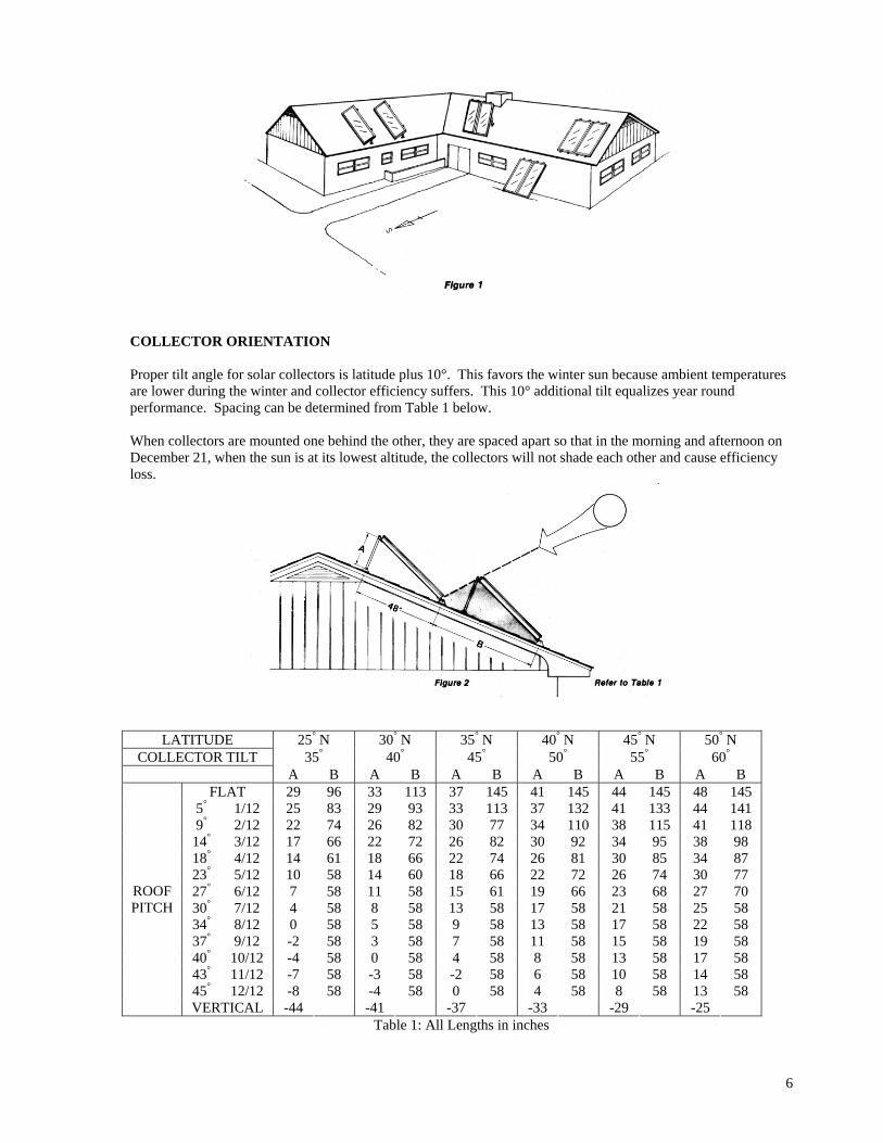
MOUNTING HARDWARE The system package includes a specially designed mounting hardware, to speed collector installation. This hardware consists of four hinge sets, four roof brackets, two rear struts, and bolts.
a) After locating the mounting points from Table 1, the mounting bracket holes should be drilled. b) A heavy coating of sealant should be applied to the bottom of the flashing plate, which should fit flat
against the roof. It is necessary for the plate to slide under the above shingles to insure proper drainage of water.
c) The bottom of the roof bracket and the area around the threaded rod should also be thoroughly coated with tar sealant. When the bracket is set in place, alignment with the collector hinges is necessary before final tightening of the nuts. This should be completed before the sealant has time to set.
d) The threaded rod is fastened through a 2’ x 6” wood or 2” x 2” x ¼” steel angle bracket under the roof as shown.
e) Spacer blocks are required when the threaded rod is 2” or more from the rafter member (see Figure 7) The rear struts should be cut and drilled to conform to Table 1. All bolts should be tightened securely. A stainless steel washer should be placed where the threaded rod passes through the aluminum bracket. It is very important that the penetrations through the roof be well sealed. It should be carefully checked that all bolts are coated with tar and that no leaks are possible.
7
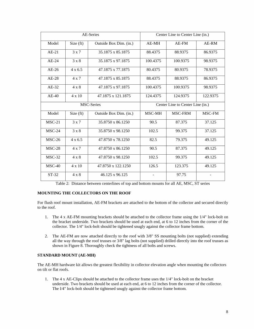
AE-Series Center Line to Center Line (in.)
Model Size (ft) Outside Box Dim. (in.) AE-MH AE-FM AE-RM
AE-21 3 x 7 35.1875 x 85.1875 88.4375 88.9375 86.9375
AE-24 3 x 8 35.1875 x 97.1875 100.4375 100.9375 98.9375
AE-26 4 x 6.5 47.1875 x 77.1875 80.4375 80.9375 78.9375
AE-28 4 x 7 47.1875 x 85.1875 88.4375 88.9375 86.9375
AE-32 4 x 8 47.1875 x 97.1875 100.4375 100.9375 98.9375
AE-40 4 x 10 47.1875 x 121.1875 124.4375 124.9375 122.9375
MSC-Series Center Line to Center Line (in.)
Model Size (ft) Outside Box Dim. (in.) MSC-MH MSC-FRM MSC-FM
MSC-21 3 x 7 35.8750 x 86.1250 90.5 87.375 37.125
MSC-24 3 x 8 35.8750 x 98.1250 102.5 99.375 37.125
MSC-26 4 x 6.5 47.8750 x 78.1250 82.5 79.375 49.125
MSC-28 4 x 7 47.8750 x 86.1250 90.5 87.375 49.125
MSC-32 4 x 8 47.8750 x 98.1250 102.5 99.375 49.125
MSC-40 4 x 10 47.8750 x 122.1250 126.5 123.375 49.125
ST-32 4 x 8 46.125 x 96.125 - 97.75 -
Table 2: Distance between centerlines of top and bottom mounts for all AE, MSC, ST series MOUNTING THE COLLECTORS ON THE ROOF For flush roof mount installation, AE-FM brackets are attached to the bottom of the collector and secured directly to the roof.
1. The 4 x AE-FM mounting brackets should be attached to the collector frame using the 1/4" lock-bolt on the bracket underside. Two brackets should be used at each end, at 6 to 12 inches from the corner of the collector. The 1/4" lock-bolt should be tightened snugly against the collector frame bottom.
2. The AE-FM are now attached directly to the roof with 3/8" SS mounting bolts (not supplied) extending
all the way through the roof trusses or 3/8" lag bolts (not supplied) drilled directly into the roof trusses as shown in Figure 8. Thoroughly check the tightness of all bolts and screws.
STANDARD MOUNT (AE-MH) The AE-MH hardware kit allows the greatest flexibility in collector elevation angle when mounting the collectors on tilt or flat roofs.
1. The 4 x AE-Clips should be attached to the collector frame uses the 1/4" lock-bolt on the bracket underside. Two brackets should be used at each end, at 6 to 12 inches from the corner of the collector. The l/4" lock-bolt should be tightened snugly against the collector frame bottom.
8
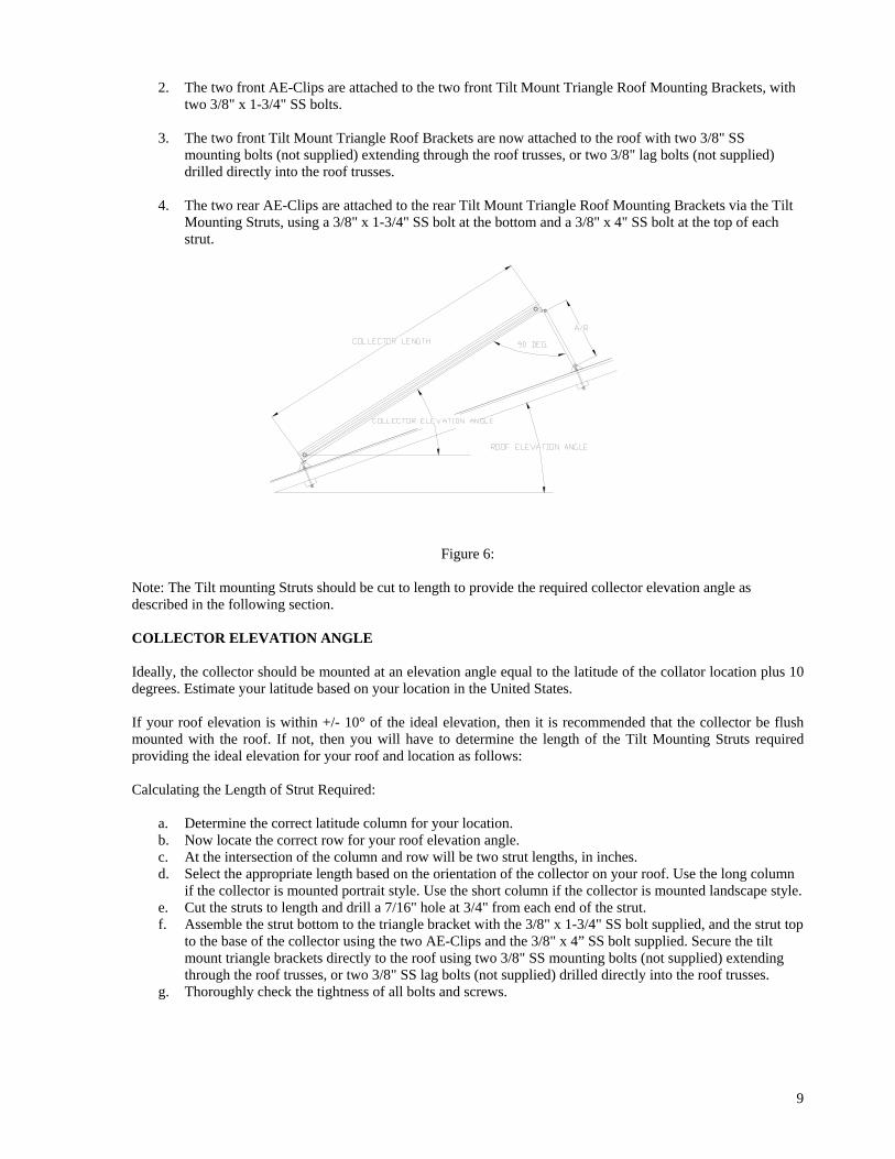
2. The two front AE-Clips are attached to the two front Tilt Mount Triangle Roof Mounting Brackets, with two 3/8" x 1-3/4" SS bolts.
3. The two front Tilt Mount Triangle Roof Brackets are now attached to the roof with two 3/8" SS
mounting bolts (not supplied) extending through the roof trusses, or two 3/8" lag bolts (not supplied) drilled directly into the roof trusses.
4. The two rear AE-Clips are attached to the rear Tilt Mount Triangle Roof Mounting Brackets via the Tilt
Mounting Struts, using a 3/8" x 1-3/4" SS bolt at the bottom and a 3/8" x 4" SS bolt at the top of each strut.
Figure 6: Note: The Tilt mounting Struts should be cut to length to provide the required collector elevation angle as described in the following section. COLLECTOR ELEVATION ANGLE Ideally, the collector should be mounted at an elevation angle equal to the latitude of the collator location plus 10 degrees. Estimate your latitude based on your location in the United States. If your roof elevation is within +/- 10° of the ideal elevation, then it is recommended that the collector be flush mounted with the roof. If not, then you will have to determine the length of the Tilt Mounting Struts required providing the ideal elevation for your roof and location as follows: Calculating the Length of Strut Required:
a. Determine the correct latitude column for your location. b. Now locate the correct row for your roof elevation angle. c. At the intersection of the column and row will be two strut lengths, in inches. d. Select the appropriate length based on the orientation of the collector on your roof. Use the long column
if the collector is mounted portrait style. Use the short column if the collector is mounted landscape style. e. Cut the struts to length and drill a 7/16" hole at 3/4" from each end of the strut. f. Assemble the strut bottom to the triangle bracket with the 3/8" x 1-3/4" SS bolt supplied, and the strut top
to the base of the collector using the two AE-Clips and the 3/8" x 4” SS bolt supplied. Secure the tilt mount triangle brackets directly to the roof using two 3/8" SS mounting bolts (not supplied) extending through the roof trusses, or two 3/8" SS lag bolts (not supplied) drilled directly into the roof trusses.
g. Thoroughly check the tightness of all bolts and screws.
9
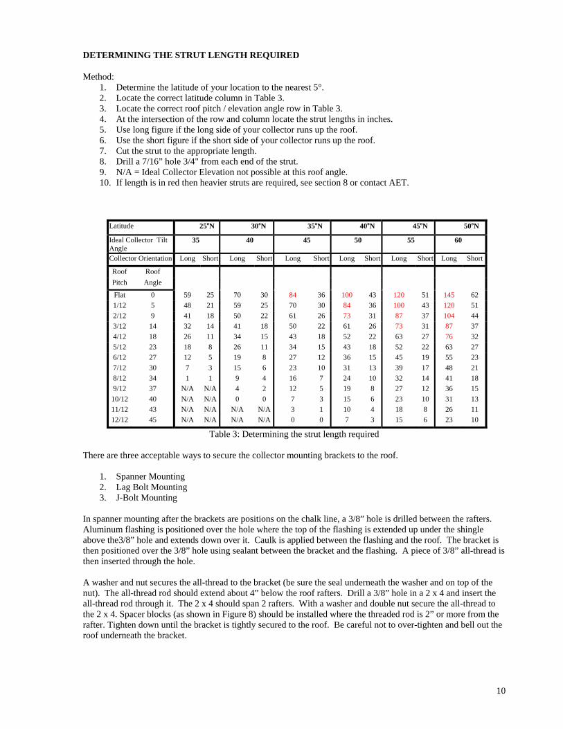
DETERMINING THE STRUT LENGTH REQUIRED Method:
1. Determine the latitude of your location to the nearest 5°. 2. Locate the correct latitude column in Table 3. 3. Locate the correct roof pitch / elevation angle row in Table 3. 4. At the intersection of the row and column locate the strut lengths in inches. 5. Use long figure if the long side of your collector runs up the roof. 6. Use the short figure if the short side of your collector runs up the roof. 7. Cut the strut to the appropriate length. 8. Drill a 7/16” hole 3/4" from each end of the strut. 9. N/A = Ideal Collector Elevation not possible at this roof angle. 10. If length is in red then heavier struts are required, see section 8 or contact AET.
Latitude 25oN 30oN 35oN 40oN 45oN 50oN
Ideal Collector Tilt Angle
35 40 45 50 55 60
Collector Orientation Long Short Long Short Long Short Long Short Long Short Long Short
Roof Roof Pitch Angle
Flat 0 59 25 70 30 84 36 100 43 120 51 145 62 1/12 5 48 21 59 25 70 30 84 36 100 43 120 51 2/12 9 41 18 50 22 61 26 73 31 87 37 104 44 3/12 14 32 14 41 18 50 22 61 26 73 31 87 37 4/12 18 26 11 34 15 43 18 52 22 63 27 76 32 5/12 23 18 8 26 11 34 15 43 18 52 22 63 27 6/12 27 12 5 19 8 27 12 36 15 45 19 55 23 7/12 30 7 3 15 6 23 10 31 13 39 17 48 21 8/12 34 1 1 9 4 16 7 24 10 32 14 41 18 9/12 37 N/A N/A 4 2 12 5 19 8 27 12 36 15 10/12 40 N/A N/A 0 0 7 3 15 6 23 10 31 13 11/12 43 N/A N/A N/A N/A 3 1 10 4 18 8 26 11 12/12 45 N/A N/A N/A N/A 0 0 7 3 15 6 23 10
Table 3: Determining the strut length required
There are three acceptable ways to secure the collector mounting brackets to the roof.
1. Spanner Mounting 2. Lag Bolt Mounting 3. J-Bolt Mounting
In spanner mounting after the brackets are positions on the chalk line, a 3/8” hole is drilled between the rafters. Aluminum flashing is positioned over the hole where the top of the flashing is extended up under the shingle above the3/8” hole and extends down over it. Caulk is applied between the flashing and the roof. The bracket is then positioned over the 3/8” hole using sealant between the bracket and the flashing. A piece of 3/8” all-thread is then inserted through the hole. A washer and nut secures the all-thread to the bracket (be sure the seal underneath the washer and on top of the nut). The all-thread rod should extend about 4” below the roof rafters. Drill a 3/8” hole in a 2 x 4 and insert the all-thread rod through it. The 2 x 4 should span 2 rafters. With a washer and double nut secure the all-thread to the 2 x 4. Spacer blocks (as shown in Figure 8) should be installed where the threaded rod is 2” or more from the rafter. Tighten down until the bracket is tightly secured to the roof. Be careful not to over-tighten and bell out the roof underneath the bracket.
10
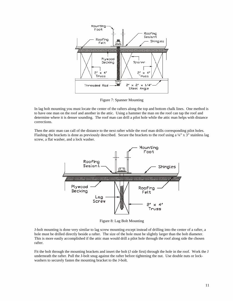
Figure 7: Spanner Mounting In lag bolt mounting you must locate the center of the rafters along the top and bottom chalk lines. One method is to have one man on the roof and another in the attic. Using a hammer the man on the roof can tap the roof and determine where it is denser sounding. The roof man can drill a pilot hole while the attic man helps with distance corrections. Then the attic man can call of the distance to the next rafter while the roof man drills corresponding pilot holes. Flashing the brackets is done as previously described. Secure the brackets to the roof using a ¼” x 3” stainless lag screw, a flat washer, and a lock washer.
Figure 8: Lag Bolt Mounting
J-bolt mounting is done very similar to lag screw mounting except instead of drilling into the center of a rafter, a hole must be drilled directly beside a rafter. The size of the hole must be slightly larger than the bolt diameter. This is more easily accomplished if the attic man would drill a pilot hole through the roof along side the chosen rafter. Fit the bolt through the mounting brackets and insert the bolt (J side first) through the hole in the roof. Work the J underneath the rafter. Pull the J-bolt snug against the rafter before tightening the nut. Use double nuts or lock-washers to securely fasten the mounting bracket to the J-bolt.
11
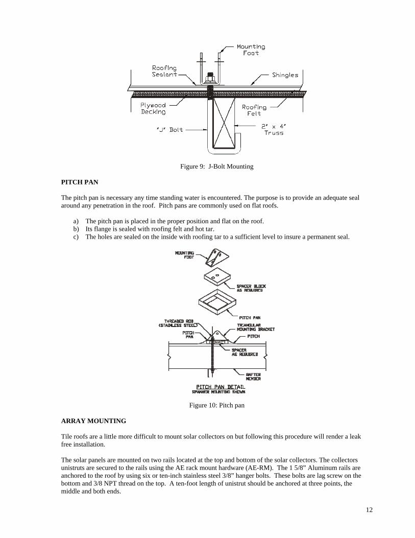
Figure 9: J-Bolt Mounting
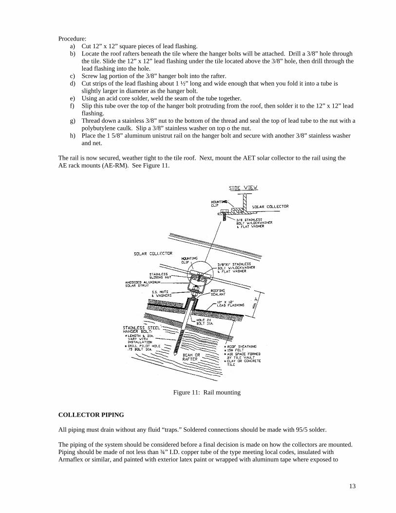
PITCH PAN The pitch pan is necessary any time standing water is encountered. The purpose is to provide an adequate seal around any penetration in the roof. Pitch pans are commonly used on flat roofs.
a) The pitch pan is placed in the proper position and flat on the roof. b) Its flange is sealed with roofing felt and hot tar. c) The holes are sealed on the inside with roofing tar to a sufficient level to insure a permanent seal.
Figure 10: Pitch pan
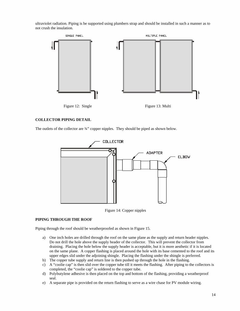
ARRAY MOUNTING Tile roofs are a little more difficult to mount solar collectors on but following this procedure will render a leak free installation. The solar panels are mounted on two rails located at the top and bottom of the solar collectors. The collectors unistruts are secured to the rails using the AE rack mount hardware (AE-RM). The 1 5/8” Aluminum rails are anchored to the roof by using six or ten-inch stainless steel 3/8” hanger bolts. These bolts are lag screw on the bottom and 3/8 NPT thread on the top. A ten-foot length of unistrut should be anchored at three points, the middle and both ends.
12
Procedure: a) Cut 12” x 12” square pieces of lead flashing. b) Locate the roof rafters beneath the tile where the hanger bolts will be attached. Drill a 3/8” hole through
the tile. Slide the 12” x 12” lead flashing under the tile located above the 3/8” hole, then drill through the lead flashing into the hole.
c) Screw lag portion of the 3/8” hanger bolt into the rafter. d) Cut strips of the lead flashing about 1 ½” long and wide enough that when you fold it into a tube is
slightly larger in diameter as the hanger bolt. e) Using an acid core solder, weld the seam of the tube together. f) Slip this tube over the top of the hanger bolt protruding from the roof, then solder it to the 12” x 12” lead
flashing. g) Thread down a stainless 3/8” nut to the bottom of the thread and seal the top of lead tube to the nut with a
polybutylene caulk. Slip a 3/8” stainless washer on top o the nut. h) Place the 1 5/8” aluminum unistrut rail on the hanger bolt and secure with another 3/8” stainless washer
and net. The rail is now secured, weather tight to the tile roof. Next, mount the AET solar collector to the rail using the AE rack mounts (AE-RM). See Figure 11.
Figure 11: Rail mounting
COLLECTOR PIPING All piping must drain without any fluid “traps.” Soldered connections should be made with 95/5 solder. The piping of the system should be considered before a final decision is made on how the collectors are mounted. Piping should be made of not less than ¾” I.D. copper tube of the type meeting local codes, insulated with Armaflex or similar, and painted with exterior latex paint or wrapped with aluminum tape where exposed to
13
ultraviolet radiation. Piping is be supported using plumbers strap and should be installed in such a manner as to not crush the insulation.
Figure 12: Single Figure 13: Multi
COLLECTOR PIPING DETAIL The outlets of the collector are ¾” copper nipples. They should be piped as shown below.
Figure 14: Copper nipples
PIPING THROUGH THE ROOF Piping through the roof should be weatherproofed as shown in Figure 15.
a) One inch holes are drilled through the roof on the same plane as the supply and return header nipples. Do not drill the hole above the supply header of the collector. This will prevent the collector from draining. Placing the hole below the supply header is acceptable, but it is more aesthetic if it is located on the same plane. A copper flashing is placed around the hole with its base cemented to the roof and its upper edges slid under the adjoining shingle. Placing the flashing under the shingle is preferred.
b) The copper tube supply and return line is then pushed up through the hole in the flashing. c) A “coolie cap” is then slid over the copper tube till it meets the flashing. After piping to the collectors is
completed, the “coolie cap” is soldered to the copper tube. d) Polybutylene adhesive is then placed on the top and bottom of the flashing, providing a weatherproof
seal. e) A separate pipe is provided on the return flashing to serve as a wire chase for PV module wiring.
14
Figure 15: Piping through roof
STORAGE TANK PLACEMENT To minimize expense and heat loss, the tank should be placed near the collectors and central to points of greatest water demand. It should be located in as warm a spot as possible, away from areas which would subject the drainback reservoir to freezing temperatures. It should be located with adequate ventilation, with a minimum of 6-8 inches of clearance and with ready access to controls and serviceable parts. Provision should be made to prevent water damage in case of leakage. A catch pan with a minimum of ¾” drain line at least 2” in height may be installed and pitched for proper drainage. A pressure and temperature relief valve must be installed on the storage tank. PLUMBING TO THE COLLECTORS All pipe runs between the solar collectors must be solidly attached with proper clamping methods and properly insulated with 1/2" minimum Armstrong Armaflex, or equal rubber type insulation, pipe insulation (pipe insulation should be rated for 230°F). Insulate all hot water piping, as well as all of the exposed cold water piping at the entrance to the solar tank. Pipe insulation, exposed to the sun, should be painted with a latex based insulation paint to resist UV degradation. The collector plumbing loop requires;
• check valve – controls the flow of the heat transfer fluid and prevents reverse thermosiphon • pressure relief valve - allows for the blow-off of pressure due to unexpected temperature increases • air vent – to bleed off air during the system charging • isolation valves – allows for system maintenance (when required) • drain valves – allows for the charging and/or draining of the system • mixing “anti-scald” valve – used to limit the temperature of the heated water to the fixtures • expansion tank – allows for expected pressure variations to do temperature fluctuations • pressure gauge – (visual monitor) insures the system is operating within the normal design pressure range
All plumbing connections to the solar panels should be made with copper pipe only. CVPC may not be attached to the solar collectors, as very high temperatures may be reached on hot summer days. Multiple collectors must always be connected in parallel as shown in the plumbing schematic. Installation of an anti-scald valve is required. This is an automatic cold water mixer on the hot water side of the tank, which supplies hot water to the house. Refer to the system drawing and the illustrations on page 19, of this document, for the installation location of this valve. Only ASSE 1016 and 1017 certified valves are to be used with this system. See the system parts list, on pages 27-28 of this document, for the valve recommended for this system.
15
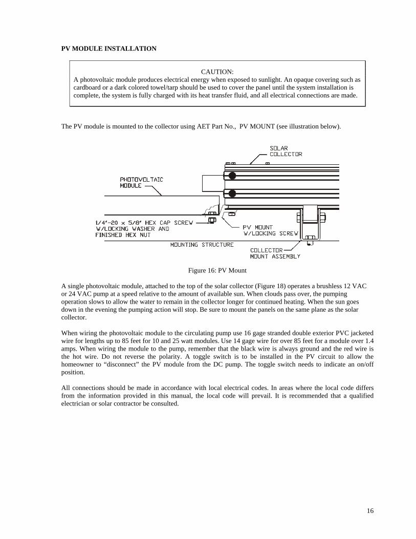
PV MODULE INSTALLATION
CAUTION:
A photovoltaic module produces electrical energy when exposed to sunlight. An opaque covering such as cardboard or a dark colored towel/tarp should be used to cover the panel until the system installation is complete, the system is fully charged with its heat transfer fluid, and all electrical connections are made.
The PV module is mounted to the collector using AET Part No., PV MOUNT (see illustration below).
Figure 16: PV Mount A single photovoltaic module, attached to the top of the solar collector (Figure 18) operates a brushless 12 VAC or 24 VAC pump at a speed relative to the amount of available sun. When clouds pass over, the pumping operation slows to allow the water to remain in the collector longer for continued heating. When the sun goes down in the evening the pumping action will stop. Be sure to mount the panels on the same plane as the solar collector. When wiring the photovoltaic module to the circulating pump use 16 gage stranded double exterior PVC jacketed wire for lengths up to 85 feet for 10 and 25 watt modules. Use 14 gage wire for over 85 feet for a module over 1.4 amps. When wiring the module to the pump, remember that the black wire is always ground and the red wire is the hot wire. Do not reverse the polarity. A toggle switch is to be installed in the PV circuit to allow the homeowner to “disconnect” the PV module from the DC pump. The toggle switch needs to indicate an on/off position. All connections should be made in accordance with local electrical codes. In areas where the local code differs from the information provided in this manual, the local code will prevail. It is recommended that a qualified electrician or solar contractor be consulted.
16
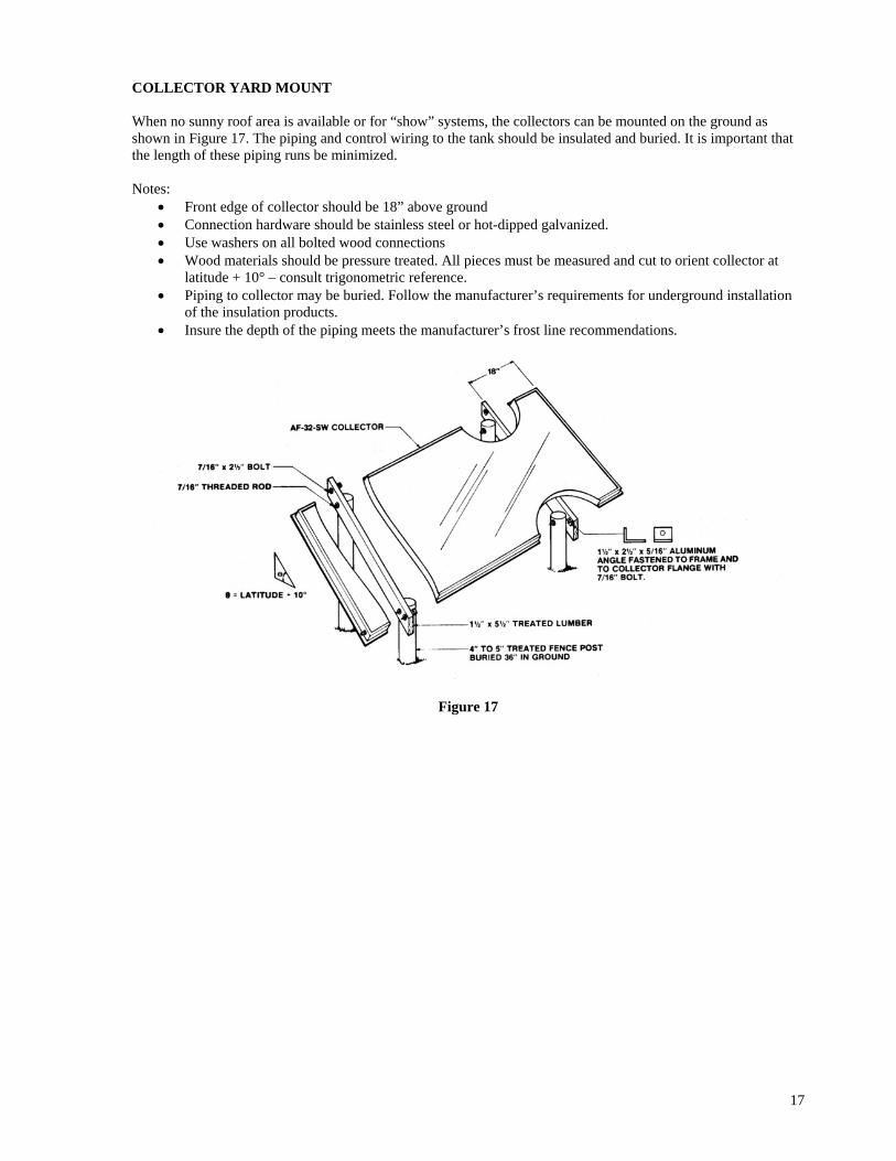
COLLECTOR YARD MOUNT When no sunny roof area is available or for “show” systems, the collectors can be mounted on the ground as shown in Figure 17. The piping and control wiring to the tank should be insulated and buried. It is important that the length of these piping runs be minimized. Notes:
• Front edge of collector should be 18” above ground • Connection hardware should be stainless steel or hot-dipped galvanized. • Use washers on all bolted wood connections • Wood materials should be pressure treated. All pieces must be measured and cut to orient collector at
latitude + 10° – consult trigonometric reference. • Piping to collector may be buried. Follow the manufacturer’s requirements for underground installation
of the insulation products. • Insure the depth of the piping meets the manufacturer’s frost line recommendations.
Figure 17
17
OPERATION INSTRUCTIONS
18
THEORY OF OPERATION
As the sun comes up in the morning and starts to shine on the solar collectors, the collectors begin to heat up. The sun’s heat energy is absorbed by the collectors and is transferred to a heat transfer fluid contained within the collector “absorber” manifold. At the same time, the photovoltaic (PV) module begins to collect the sun’s light energy and converts it into electrical energy, providing power to a circulation pump. The photovoltaic module acts as the system control mechanism, only providing power to the pump when sufficient sunlight is available. The circulation pump is very quiet, so you may not notice when it is on and when it is off. The system collects heat by circulating the heated transfer fluid from the collectors, to the heat exchanger contained in the storage tank. The heat energy is transferred into the storage tank and the now cooler transfer fluid is circulated back up to the collectors where the process is repeated. This process is repeated continually throughout the day, so that by the end of the day, the water in the storage tank is hot. The quantity and size of the solar collectors are matched to provide enough heat energy to thoroughly heat all of the water contained in the storage tank. This is all done automatically and requires no interaction on the part of the system owner. Freeze protection is provided by employing an anti-freeze agent as the heat transfer fluid. Food grade, non-toxic propylene glycol is recommended. Please refer to the Parts Listing, at the end of this document, for recommended suppliers. All solar systems will have a backup source of heating. A common backup source is gas or electric water heater. Backup sources are used because on some days, when it is very cloudy, the solar contribution will be very small. On days when there is plenty of sun, and the sun is doing the work of heating the water automatically, the resulting high water temperature in the tank will keep the internal hot water heater thermostat from turning on the gas or electric heat, thus saving fuel and money. EAGLE SUN™ SYSTEM COMPONENTS This system is comprised to the following components (AET Replacement Part #’s):
• Solar collector(s) - (AE or MSC Series) • One circulation pump - (CP809-12 or CP809-24) • One photovoltaic module - (PV-10 or PV-20) • One storage tank - (CST-80E w/T&P relief valve) • One check valve - (CV-50) • One pressure relief valve - (PR-150) • One air vent - (AV-150) • Two isolation valves - (BV-50) • Two drain valves - (BD-50) • One “anti-scald” valve - (AM101-C) • One expansion tank - (ET-20) • One pressure gauge - (PG-100)
THE SOLAR COLLECTORS The collector array consists of solar collectors of sufficient size to meet the design criteria for your household needs and geographic area, plus a set of 4 mounting brackets for each solar collector. The collectors are the Alternate Energy Technologies, AE or MSC series, using Thermafin absorbers with Selective Crystal Clear Black coating. The Crystal Clear Black surface has been proven to withstand very high temperatures for long periods of time and will not flake or chip. It is a revolutionary coating, which is actually a crystalline structure that is "grown" on the surface of the copper plating material. Crystal Clear Black coating is a leading edge technology that allows the maximum amount of solar energy to be absorbed at the lowest light level and virtually eliminates the amount of energy reflected to the sky.
19
The absorber plate within the collector is made of Thermafin risers. Using a high frequency forge welded molecular bond between copper tube and copper fin to form the risers that make up the absorber plate. Thermafin is designed to conduct the maximum amount of heat absorbed to the fluid that passes through the tube and returns to the storage tank. Unlike other methods, that solder or braze the tube and fin, Thermafin has only copper to conduct the heat and is therefore the most efficient product available. The glass on the solar collector is a low iron tempered glass of exceptional clarity. This means that sunlight coming into the collector loses very little energy and transforms almost all of the light into heat. The tempered glass is very strong and resists damage that ordinary window glass could never withstand. A high-density foam material is used to provide insulation and minimize heat loss in cold weather. All copper piping is externally sealed with high temperature silicone grommets. All of this ensures that the maximum heat energy is transferred to the water, which is stored for use as needed. The aluminum frame of the collector consists of extruded aluminum, with an integral quick lock-mounting rail for ease of installation with our patented "Quick lock" mounting hardware. The mounting brackets come in a set of 4 per solar panel, and all hardware is included except for the actual bolt used to attach to the roof or mounting surface. All fasteners and bolts are made of high quality and long lasting stainless steel. THE STORAGE TANK The water storage tank used in this system is similar in construction to that of a standard water heater. This water heater is equipped with additional inlet/outlet ports to accommodate the solar interface. The water storage tank, stores the heat energy generated by the solar system. As the pumps circulate the fluids throughout the system, the fluids become hot and this heat energy is transferred to the water in the storage tank. This large volume of heated water used as the hot water source for the fixtures in the building/residence. THE CIRCULATION PUMP A pump is used to circulate the heat transfer fluid in the collector plumbing loop. The circulation pump is matched to complement the electrical characteristics of the PV module. The pump is very quiet, efficient, and reliable. The pump should be located on the feed pipe to the collectors below the top of the water storage tank. THE PHOTOVOLTAIC MODULE (Controller) A photovoltaic (PV) module mounted adjacent to and in the same plane as the solar collector, controls the on/off function of the solar system. The PV module provides direct current (DC) to the circulation pump only when sufficient solar energy is available. In the event of an emergency, the system can easily be shut down by simply positioning the toggle switch to the “off” position. This will break the electrical connection and de-energize the pump. THE HEAT EXCHANGER The heat exchanger used in this system is of the wrap-around type. It is integral to the water storage tank and is used to transfer the heat energy collected by the solar collectors to the water in the storage tank.. THE HEAT TRANSFER FLUID The heat transfer fluid carries the heat energy, generated in the solar collectors, to the storage tank where the heat is transferred to the potable water within the storage tank. Eagle Sun™ Systems are designed to use solutions of non-toxic propylene glycol and water. Products such as Dow Chemicals – Dowfrost and Old World Industries – SIERRA Antifreeze are acceptable glycol solutions. FREEZE PROTECTION Eagle Sun™ Systems use an anti-freeze solution as the primary freeze protection device. Specific concentrations will vary with geographic location and install conditions. Manual intervention is required where temperatures are expected to fall below the freeze tolerance limit of -20°F (-28.9°C). The system should be isolated, drained and power to the pump should be disconnected to avoid “dry-run” pump damage.
20
“Freeze tolerance limits are based upon an assumed set of environmental conditions. Extended periods of cold weather, including ambient air temperatures above the specified limit, may cause freezing in exposed parts of the system. It is the owner’s responsibility to protect the system in accordance with the Supplier’s instructions if the air temperature is anticipated to approach the specified freeze tolerance limit.”
SYSTEM VALVES Eagle Sun™ Systems are equipped with several plumbing components designed to protect the system from excessive temperature and pressure related issues. Air vent – allows air trapped in the system to escape, preventing air lock which would restrict fluid flow. Temperature and pressure relief valve – installed on the storage tank, the T&P relief valve insures that excessive temperatures and system pressure is adequately relieved as needed. Pressure relief valve – protects the collector loop components from the build up of excessive pressure. Isolation valve(s) – used to isolate the system when is need of maintenance or repair. Boiler drain(s) – used to drain/fill the system when is need of maintenance or repair. Check valve – used to prevent thermosiphon losses (see note below) of the system. Anti-scald valve – required to maintain safe water temperatures to the fixtures. Expansion tank – provides room for the expansion of the heat transfer fluid in the system. Pressure gauge – used to monitor the pressure within the collector plumbing loop. NOTE: The thermosiphon effect - in a column of water, heat will always attempt to rise (flow) to the highest point in the column. As the water is heated, it expands slightly and begins to rise. The colder, denser water falls to the lowest point and, thus, a natural circulation begins. In a solar system, during the evening hours when the system is not in operation, the storage tank can act as a heat source. The heat exchanger draws heat from the storage tank. The heated transfer fluid begins to rise and the colder fluid, in the solar collectors, begins to fall. This natural flow can allow the night sky to rob the storage tank of its heat. A check valves are used to impede the reverse flow (reverse to the flow direction of the pump) of the heat transfer fluid. OPERATING INDICATORS Temperatures gauges are installed on the feed/return lines, to/from the collectors to allow the system owner to easily identify the when the solar collectors are working properly. The return line from the collectors should be hotter than the feed line. A properly installed solar system should provide a temperature differential of 10-20°F. FLUID SAFETY LABELING Included with your Drainback system is a set of labels which describe the component function. These labels are necessary to alert the owner of potential hazards. These labels are affixed by string/wire tie (on valves) and/or “peel-and-stick” (on pipe insulation). All labeling must be in place at final inspection. Label examples are as shown on the following page.
21
START-UP OF A CLOSED LOOP PV SYSTEM Photovoltaic (PV) pumped systems should be charged when adequate sunlight is available to power the system pump. Care should be taken when working with PV modules. Power is generated anytime sufficient sunlight is available. During the installation process, the PV module should be covered with an opaque covering (i.e., cardboard or dark colored cloth) until the system is fully charged and checked for leaks.
After installation and final inspection the system should be filled and checked for leaks at 1½ times the normal working pressure for at least ½ hour. The collector side should be filled with a solution of non-toxic antifreeze such as propylene glycol and water. The mixture should be of adequate concentration for freeze conditions in the geographical location of the system. The simplest way to fill and pressurize this half of the system is with a drill pump, 5 gallon bucket and 3 washing machine hoses. The final system pressure should be the height of the collectors above the tank divided by 2.31 plus 20 psi, not to exceed 30 psi when cold. The expansion tank should be charged to the same pressure as the final system pressure, less 2 to 3 psi. To charge the system:
1. In a 5 gallon bucket, mix a 50-50 solution of propylene glycol and water. Allow 1.5 to 2 gallons of solution per collector and 2 gallons for the plumbing.
2. Attach a washing machine hose the bottom (return) drain valve in the solar plumbing loop. Place the opposite end of the hose into the 5 gallon bucket.
3. Attach a second washing machine hose to the upper (feed) drain valve in the solar plumbing loop. Attach the opposite end of the hose to the outbound (pressure) port of the drill pump.
4. Attach a third washing machine hose to the inbound (suction) side of the drill pump. Place the opposite end of the hose into the 5 gallon bucket.
5. Check to insure the air vent cap is loosened roughly two turns to allow air to escape form the plumbing loop.
6. Open both the feed and return drain valves. 7. Energize the drill pump to begin filling the loop. Initially, air will exit from the return drain valve hose.
Allow the pump to run for several minutes or until the fluid runs freely (without air) from the return drain valve.
8. Close the return drain valve and continue to pump fluid into the loop until the pressure gauge reads approximately 28 PSI.
9. Close the feed valve and de-energize the pump. Closing the drain valve first will insure pressure is maintained in the loop. Allow the fluid to settle for several minutes. The remaining air trapped in the loop will rise to the highest point (at the air vent).
10. Remove the cap from the air vent and press down on the center pin of the Schraeder valve using a screw driver (or similar instrument) to insure all air has escaped. Only fluid should come out of the valve. CAUTION: The fluid may be hot. Take care when performing this step.
11. Replace the cap on the air vent and loosen roughly two turns. 12. Remove the coverings from the solar collectors and the photovoltaic module. If adequate sunlight is
available, the pump should energize and the solution should begin to circulate. The return lines from the collectors should be hotter than the inlet lines and the collector glass should be slightly warmer than the ambient air temperature.
13. Check the system pressure and make adjustments if necessary. 14. Remove all of the hoses from the drain valves and discard the remaining glycol/water solution as
recommended by the manufacturer. Closed loop system maintenance includes changing the antifreeze solution every four years, or when the PH of the fluid becomes unstable. To do this, the system should be drained, flushed with fresh water and recharged as described above. The pressure gauge will indicate any system leakage. The collector and PV module glazings (glass) should be kept clean for best system performance. Rain water will usually suffice, but a garden hose will help during dry periods. The air vent cap should be loosened two turns for best performance.
22
SERVICE / MAINTENANCE PROCEDURES
23
SHUT DOWN PROCEDURE To shut down the Eagle Sun™ System, simply cover the solar collectors and the PV module with an opaque covering such as cardboard or a dark towel/tarp and the pump will stop. Secure the coverings to insure they do not blow off while performing service to the system.
CAUTION! Allow the system to cool prior to draining. Fluids will be hot!
DRAINING THE SYSTEM
1. Shut down the system as described above and allow the system to cool. 2. Remove the air vent from the collector plumbing loop. 3. Attach washing machine hoses to the top (feed) and bottom (return) drain valves. Place the opposite ends
into a 5 gallon bucket. 4. Open both of the drain valves. The plumbing loop will gravity drain to a level equal to the highest point
in the lowest drain hose (tilting the bucket may allow for the draining of additional fluid). 5. Once the system has drained, close the drain valves and remove the washing machine hoses. 6. Dispose of the “spent” heat transfer fluids per the manufacturer’s recommendation. 7. Replace the air vent to prepare for recharging the system.
TROUBLE SHOOTING GUIDE Problems with systems usually fall under two categories: system leaks or lack of sufficient solar heated water. LEAKS If leaks exist, the system should be shut down for repairs. Cover the solar collectors and the PV module. Close off the cold water inlet or in case of a leak in the closed loop system, isolate as much of the system as possible. Allow sufficient time for the system to cool, then drain and repair the affected area. There is a possibility that what appears to be leaks may be condensation on the pipes. Also water escaping for the T&P valve may be an indication of proper function as they are designed to vent off excess temperature and pressure. INSUFFICIENT HOT WATER If insufficient hot water is available a system malfunction may not be indicated. A low amount of solar radiation or heavy water demand can be the cause. If no excessive demands are put on the system and ample solar radiation is available, the system should operate properly. The pump should run each sunny day until a full supply of hot water is stored. If the pump does not run, there is a problem on the electrical end of the system. Either the pump, PV module, or interconnect wiring is malfunctioning. To check the pump, cover and disconnect the PV module. Disconnect the pump from the interconnect wiring and connect an alternative 12VDC power supply to the pump (i.e., 12V battery, 12VDC battery charger or power converter). If the pump runs, check the interconnect wiring, if not, replace the pump. With the wiring connections open (disconnected) at both ends, attached an Ohm meter to the open connection at one end. If the meter beeps, there is a short between the wires. If no sound is heard, no short is present. Twist the interconnect wires together at one end and attach the Ohm meter at the opposite end. The meter should beep, if no sound is heard, there is a break in the wiring. Repair or replace if necessary. If all tests well, reconnect the components and consult an electrician for help with testing the PV module.
24
CONDENSATION ON COLLECTORS If condensation occurs inside the collectors, ¼” vent holes should be drilled in the lower side of the collector. Three holes should be drilled, one at each end of the bottom of the collector and one in the center. These holes should be drilled 1” from the base of the collector This should clear up any condensation within three days. OTHER PROBLEMS A noisy pump is an indication of worn bearings, obstruction or loss of prime. As a rule of thumb, an 8-12° temperature gain should be expected across a collector, in bright sun, at the proper flow rate. MAINTENANCE ROUTINE MAINTENANCE In areas of infrequent rain the collector glazing should be visually inspected on a periodic basis (once a quarter) and cleaned with a hose if necessary. Closed loop system maintenance includes changing the antifreeze solution every four years, or when the PH of the fluid becomes unstable. To do this, the system should be drained, flushed with fresh water and recharged as described above. The pressure gauge will indicate any system leakage. The storage tank should be flushed on an annual or bi-annual basis following the manufacturer's recommendations. Exterior pipe insulation should be treated as required with an exterior UV inhibitor paint. Contact your authorized AET Dealer if you feel insulation needs re-coating or replacement. NON-ROUTINE MAINTENANCE / TROUBLESHOOTING In case of a leak in the collector system, first attempt to identify the source of the leak, then cover the solar collectors and PV module. Since the indirect Eagle Sun™ System is already isolated from the solar storage tank via the heat exchanger, no valves need to be operated. If the leak is in the collector contact your installation contractor listed below or AET direct for instructions on how to repair or replace the absorber plate. For leaks in the potable water system or the solar storage tank, close the shut-off valve “H” and seek repair as described above.
VACATION PROCEDURES If no hot water is to be used for some time, position the toggle switch to the “off” position and place an opaque cover, such as cardboard or a tarp, over the collector(s) and PV panel. To re-energize the system, remove the coverings and toggle the switch to the “on” position.. SYSTEM PARTS LISTING COMPONENT MANUFACTURER MODEL Solar Collector(s) Alternate Energy Technologies, LLC AE or MSC Series Water Storage Tank Richmond/Rheem Water Heaters S80HE-1 or 81V80HE-1 Photovoltaic Module Various PV-10 or PV-20 Circulation Pump March Manufacturing, Inc. 809-BR-12 or 809-BR-24 Check Valve Watts Regulator 601S Temp & Pressure Relief Valve Watts Regulator 100XL Pressure Relief Valve Wilkins/Zurn Industries Ltd P1000A Air Vent Watts Regulator FV-4M1 Isolation Valve(s) Watts Regulator B6001
25
26
SYSTEM PARTS LISTING (cont.) COMPONENT MANUFACTURER MODEL Drain Valve(s) Watts Regulator BD5 Anti-Scald Valve Honeywell-Sparcomix AM101C Expansion Tank Watts Series ET ET-15 Pressure Gauge Wika Instrument Type TI.20 ESTIMATED COMPONENT LIFE When installed and maintained as directed in this manual, one can expect many years of trouble-free service from this system. All components in this system are subject to the conditions of the installation. In locations where hard water is present, mineral deposits can prematurely foul-out the design life of these components. Periodic maintenance is required to insure that these components are well protected from such damage. The solar collectors used in this system have a design life of 30+ years. Water storage tanks are designed for 12-20 years of use. The lesser components, such as pumps and valves are designed for 5+ years, however, are more likely to foul, as described above, if not maintained properly. WARRANTIES AND DISCLAIMERS Please note that we specifically exclude any warranty for, or liability from, acts of nature, including freeze damage and shading of the collectors by future growth. Warranty periods for all the major components are given below: Item Part# Period Collector(s) AE or MSC Series 10years Storage Tank S80HE-1or 81V80HE-1 6years PV Module PV-10 or PV-20 20years Circulation Pump 809-BR-12 or 809-BR-24 1 year Valves various 1 year
All parts are available from your authorized agent or from AET direct. FLUID QUALITY This system uses a solution of propylene glycol and water as a heat transfer fluid media in the solar loop.
“No other fluid shall be used that would change the original classification of this system. Unauthorized alterations to this system could result in a hazardous health condition.”
HAZARDS Solar collectors become very hot when in direct sun with no fluid being circulated through them. Extreme caution should be taken when standing near, or handling solar collectors in this state. The circulating pumps become very hot when running. Always allow at least 30 minutes for the pump to cool down before touching the pump. A photovoltaic module produces electrical energy when exposed to sunlight. An opaque covering such as cardboard or a dark colored towel/tarp should be used to cover the panel until the system installation is complete, the system is fully charged with its heat transfer fluid, and all electrical connections are made. Relief valves may discharge fluids at high temperature and/or pressure.


![Sigma 3-18KS Sigma 3-18KHS · PDF fileSigma 3-18KS Sigma 3-18KHS. ... (with 13190 and 13194) 11133 ... RFI suppression EN 61326 EN 61326 Weight without rotor [kg]](https://img.pdfslide.us/doc/110x75/5a790eff7f8b9a9a188b7ade/sigma-3-18ks-sigma-3-18khs-3-18ks-sigma-3-18khs-with-13190-and-13194-11133.jpg)