Embed Size (px)
Citation preview

INSTALLATION, OPERATION & MAINTENANCE MANUAL (IOM) IOM-DA612-16
I. DESCRIPTION AND SCOPE
The Model DA6 is a pressure loaded back pressure regulator used to control upstream (inlet or P1) pressure. Sizes are 1/2" (DN15), 3/4" (DN20), 1" (DN25), 1 1/4" (DN32), 1 1/2" (DN40), 2" (DN50), 3" (DN80) and 4" (DN100). With proper trim uti li za tion, the unit is suitable for liquid, gaseous, or steam service. Typically installed in a more com-mon “reverse” flow direction arrangement that is balanced (to outlet). Refer to Technical Bulletin DA6-TB for design conditions and selection rec om men da tions. (NOTE: This product was formerly iden ti fied as a Model D6; a Model DA6 and D6 are one and the same product.)
MODEL DA6DA6 - DIRECT-ACTING, PRESSURE LOADED
BACK PRESSURE REGULATOR
SECTION I
II. REFERENCES
Refer to Technical Bulletin DA6-TB and DAG-TB for tech ni cal specifications of a Model DA6 regulator.
ABBREVIATIONS
CCW – Counter ClockwiseCW – ClockwiseITA – Inner Trim Assembly
III. INSTALLATION
1. Install per direction of flow arrow indicated on body, or "IN" and "OUT" markings.
2. Regulator may be rotated around pipe axis 360 degrees. For ease of maintenance, the rec om- mend ed position is with the cover dome (25) up wards. In liquid service it is recommended that the cover dome (25) be oriented down wards, and that a cus tom er supplied and installed vent valve be pro vid ed at the external sensing connection to bleed-off trapped gas/air under the diaphragm during initial startup.
3. Provide space below, above, and around reg u la tor for removal of parts during maintenance.
4. Install block valves and pressure gauges to pro- vide means for adjustment, operation, bypass, or removal of the regulator. A pipeline strainer is recommended before inlet to remove typical pipe line debris from entering valve and damaging internal “soft goods”, primarily the dynamic side seal and V-TFE seat when applied.
5. Upstream Sensing Installation Considerations – Internal or External Sensing:a. The regulator may be installed with internal or
external sensing. Unless otherwise spec i fied,
the regulator is supplied by factory with internal sensing. The regulator may be con vert ed in the field to external sensing. (See Section VII Maintenance, Part H – Converting Internal/External Sensing.)
b. Reference DAG-TB, Table DAG-12 for rec om- men da tions for applying external pressure sensing.
c. For internal sensing, no external line is re- quired. For external sensing, use an external control line. The line is connected from the port 1/4" (DN8) NPT tap (Port 5 – See Fig. 5) on the side of the body di a phragm flange to a pressure tap upstream of the regulator. Use 1/4" (6.4 mm) or 3/8" (9.5 mm) outer di am e ter tubing or 3/8" (DN10) pipe having an inner di am e ter equivalent to schedule 40 pipe.
d. For condensable vapors (i.e. steam) slope the external sensing line downward 2 to 5 de grees to inlet piping to prevent water pock ets, which allows the diaphragm chamber to al ways be self draining. The external sensing line may be sloped upward for gas or liquid service; i.e. non-condensibles.
SECTION III
SECTION II
CAUTION
Installation of adequate overpressure pro tec tion is recommended to pro tect the reg u la tor from over pres sure and all down stream equip ment from dam age in the event of regulator failure.
ISO Registered Company

IOM-DA62
CAU TION
DO NOT HYDROSTATIC TEST THROUGH AN IN STALLED UNIT; ISOLATE REGULATOR FROM TEST. See Technical Bulletin DA6-TB, Table 1; Maximum P1 - Inlet Pressure levels for various diaphragm materials by valve body size. Higher pres sures could cause in ter nal dam age. The name-plate indicates the Inlet and Outlet pres sure and tem per a ture ratings.
Recommended Piping SchematicFor Back Pressure/Relief Station
V. STARTUP
1 Start with the block valves closed.
2. Adjust the loading system pressure control device so that main valve is trying to be controlled at 0 psig pressure.
IV. PRINCIPLE OF OPERATION
1. When a loading pressure – PLoad – is applied to the top side of a diaphragm, the inlet controlled pressure – P1 – will balance at approximately 0.96–0.98 of the loading pressure – PL – for the standard flow direction, and at 0.98–1.0 of the load-ing pressure – PL – for the reverse flow direction. NOTE: Fluctuations in the P2 – Outlet Pressure will cause a deviation in pressure setpoint – PSP – the “crack-open” pressure for the stan dard flow direction. This deviation is com pen sat ed away for the reverse flow direction.
2. Movement occurs as pressure variations register
SECTION IV
SECTION V
CAU TION
Do not walk away and leave a bypassed reg u la- tor unattended!
on the diaphragm. The registering pressure is the inlet, P1, or upstream pressure. The loading pressure fluid op pos es di a phragm movement. As inlet pres sure in creas es, the diaphragm push es up, opening the port; as inlet pres sure decreases, the loading pressure pushes the di a phragm down and the port open ing closes.
3. A complete diaphragm failure will cause the reg u- la tor to fail closed if in the standard flow direction variation, and tend to fail closed in the reverse flow direction but with seat leakage.
4. Loss of loading pressure while inlet pressure is imposed will cause valve to fail open.
3. Crack open manual bypass valve. Initially pres- sur ize system while simultaneously controlling P1 pressure through manual actuation of bypass valve.
4. If it is a “hot” piping system, and equipped with a bypass valve, slowly open the bypass valve to preheat the system piping and to allow slow ex pan sion of the piping. Ensure proper steam trap operation if installed. Closely monitor inlet (up stream) pressure via gauge to ensure not over-pressurizing. NOTE: If no bypass valve is in stalled, extra caution should be used in starting up a cold system; i.e. do everything slowly.
CAUTION
In the event of diaphragm failure, the process fluid will mix with the loading fluid.
CAUTION
For welded installations, all internal trim parts, seals and diaphragm(s) must be removed from reg u la tor body prior to welding into pipeline. The heat of fusion welding will dam age non-metallic parts if not re moved. NOTE: This does not apply to units equipped with extended pipe nip ples.

IOM-DA6 3
5. Open the outlet (downstream) block valve.
6. Slowly open the inlet (upstream) block valve to about 25% open, observing the inlet (upstream) pres sure gauge. The reg u la tor should be flow-ing. Adjust the loading system pressure control device setpoint pressure upwards until the main valve flow is shutoff. Observe the inlet pressure gauge to ensure not over pressurizing.
7. Continue to open inlet block valve until at least 50% open. Set loading system pressure control device upwards to approximate 80% desired main valve pressure level.
8. Fully open inlet block valve.
9. Begin to slowly close the bypass valve if installed.
10. Develop system flow to a level near its expected normal rate, and reset the regulator set point by adjusting the loading system pressure control set point to the desired level.
11. Reduce system flow to a minimum level and observe pressure set point. Inlet pressure will decrease from the set point of Step 10. The max i mum build in inlet pressure on increasing flow should not exceed 10%. If it does, consult factory.
VI. SHUTDOWN
1. Shutoff auxiliary loading pressure source.
2. Shutoff inlet block valve.
3. Shutoff the outlet block valve.
VII. MAINTENANCE
A. General:
1. The regulator may be serviced without re mov- ing the regulator from pipeline. The reg u la tor is designed with quick-change trim to simplify maintenance.
2. Record the nameplate information to req ui si- tion spare parts for the regulator. The in for ma- tion should include: size, Product Code, and Serial Number.
3. Refer to Section VIII for rec om mend ed spare parts. Only use original equip ment parts sup- plied by Cashco for re build ing or re pair ing regulators.
4. Owner should refer to owner's pro ce dures for removal, handling, cleaning and disposal of nonreusable parts, i.e. gaskets, etc.
NOTE: On regulators originally sup plied as “oxygen clean” – Opt-55, main te nance must include a level of clean li ness equal to Cashco cleaning stan dard #S-1134.
5. The Inner Trim Assembly (ITA) is re moved and re placed in the body (23) as an as sem blage of parts. The ITA con sists of the fol low ing parts:
Item Dynamic Side No. Seal Type Part Description 7 ......................All ........................Diaphragm Cap Screw 7 ......................All ...........................Diaphragm Lock Nut 8 ......................All .......Upper Diaphragm Pressure Plate 9 ......................All ......................................Diaphragm(s) 10 .....................All ..........Lower Diaphragm Pusher Plate 13 .....................All ....................... Piston/Guide Bearing√ 14 .....................All ......................................... Stem Seals 14.1 ...............All ................................ Upper Stem Seal 14.2 ...............All ................................Middle Stem Seal 14.3 ...............All ..............................Lower Stem Seal√ 14.4 ...............All ................Lower Pusher Plate Gasket 20 .....................All ...........................................Valve Plug 27 .....................All ...........................Dynamic Side Seal * 27.1 ...............CP ..................................... TFE Cap Seal 27.2 ...............CP ......................... O-ring Energizer/Seal 27.3 .............. UC .......... U-Cup Seal w/Metal Energizer 27.5 ...............PR ................................. Piston Ring Seal 27.6 ...............PR .................Piston Ring SST Energizer 28 .....................All ............................................ Seat Disc 29 .....................All ...............................Seat Disc Washer 30 .....................All ......................................Seat Disc Nut
* Possible option is with NO dynamic side seal. √ 2-1/2" thru 4" body sizes only.
SECTION VII
4. Relieve the trapped upstream and downstream pressure and loading pressure.
5. The regulator may now be removed from the pipe line or disassembled for inspection and pre- ven ta tive main te nance while in-line.
A detailed view of the dynamic side seal parts is shown in Figure 1 on the next page.
SECTION VI

IOM-DA64
Type CP— TFE Cap Dynamic Seal
Type PR — PRA Dynamic Seal
NOTE: Two separate piston rings per assembly.
Figure 1: Dynamic Side Seals
Type UC — U-Cup Dynamic Seal Type NO — No Dynamic Seal

IOM-DA6 5
B. Main Valve Disassembly:
1. Shut down the system in accordance with Section VI.
2. Disconnect the external sensing line, if in- stalled.
3. Though it is possible to disassemble the valve unit while installed in a pipe line, it is rec om- mend ed that main te nance be done in a shop when pos si ble. The descriptions hereafter will assume shop dis as sem bly. Remove valve from pipe line.
4. Place the valve unit in a vise with the cover dome (25) upwards.
5. Loosen the diaphragm flange bolts (11) and nuts (12) uniformly.
6. Place matchmarks on body (23) and cover dome (25) flang es. Completely remove bolt ing (11,12). Remove the cover dome (25).
7. Grasp opposite edges of diaphragm (9) and withdraw the ITA from within the cage (19). Set the ITA aside.
8. Evenly loosen the cage cap screws (18) in single revolution in cre ments until fully loos- ened; remove cage cap screws (18).
9. Pull cage (19) up and out of body.
10. Remove o-ring cage seal (15).
11. Remove lower cage gasket (21).
12. If supplied, remove internal sensing drilled plug (32) using 5/32" (4 mm) Allen key wrench. NOTE: Valves with “Large Internal Sensing” will not be equipped with any plug (32,33).
13. For metal diaphragm constructions, remove diaphragm gasket (37) from body (23) di a- phragm flange.
14. Remove body (23) from vise. Solvent clean all removed metal parts.
C. Disassembly of the ITA:
1. Body Sizes 1/2" – 2". (See Figures 2 thru 5):a. Obtain two pieces of square-section
barstock with a 3/8" - 7/16" dimension, approximately 2 inches long.
b. Place plug into a vise using the bars of a. above positioned on "flats" located on plug (20) to prevent vise jaw marks from direct surface contact with the plug (20). Orient with diaphragms on topside.
c. Sizes 1/2" – 1": Remove diaphragm locknut (7) by rotating CCW.
Sizes 1-1/4" – 2": Remove diaphragm cap screw (7) by rotating CCW.
d. Remove upper diaphragm pressure plate (8).
e. Remove diaphragm(s) (9, 9.1, 9.2, 9.9). Examine diaphragm(s) to determine wheth er failed; determine if operating con di tions are ex ceed ing pressure drop or temperature limits.
f. For composition diaphragm construction, remove upper stem seal (14.1).
g. For metal diaphragm construction, re move lower pusher plate gasket (14.4).
h. Remove lower diaphragm pusher plate (10).
i. Remove middle stem seal (14.2).j. Remove plug (20) from vise, rotate end-
for-end, and resecure in vise using same metal bars of a. above.
k. Loosen seat nut (30) CCW (viewed from above) ap prox i mate ly two (2) rev o lu tions.
l. Remove assembly (20, 27, 28, 29, 30) from vise. Complete removal of seat disc nut (30), seat disc washer (29), and seat disc (28).
2. Body Sizes 2-1/2" – 4". (See Figure 6):a. Place seat disc nut (30) into a vise with
the plug (20) oriented vertically. Do NOT over-tighten nut (30) in vise.
b. Place closed-end hex wrench onto di a- phragm locknut (7). Place socket wrench on 3/4" hex upper end of plug (20). Loos en diaphragm locknut (7) while holding plug (20) from rotating by socket wrench. Remove diaphragm locknut (7) after fully loosened and socket wrench is removed.
c. Remove upper diaphragm pressure plate (8).
d. Remove diaphragm(s) (9, 9.1, 9.2, 9.9). Examine diaphragm(s) to determine wheth er failed; determine if operating con di tions are ex ceed ing pressure drop or temperature limits.
WARNING
SYSTEM UNDER PRESSURE. Prior to per form ing any maintenance, isolate the reg u la tor from the system and relieve all pressure. Fail ure to do so could result in personal injury.

IOM-DA66
Figure 2: Body Sizes1/2" – 1", Composition Di a phragm
Figure 3: Body Sizes1/2" – 1", Metal Diaphragm
Figure 4: Body Sizes1-1/4" – 2", Composition Diaphragm
Figure 5: Body Sizes 1-1/4" – 2", Metal Diaphragm
e. Remove up per stem seal (14.1).f. Remove lower diaphragm push er plate
(10).g. Remove middle stem seal (14.2).h. Remove piston/guide bearing (13) with
dynamic side seal (27) in place.i. Remove lower stem seal (14.3).j. Place socket wrench on upper end of plug
(20) as in Step b. above. Ro tate plug (20) CCW (viewed from above) to loosen seat disc nut (30). Once nut (30) is loos ened, re move partial as sem bly (20, 27, 28, 29, 30) from vise. Complete re mov al of seat disc nut (30), seat disc washer (29) and seat disc (28).
3. Examine the components (27.1, 27.2, 27.3, 27.4, 27.5, 27.6) of the dynamic side seal (27) to determine if sig nif i cant leak age was oc cur- ring. If the dynamic side seal (27) shows signs of significant leakage, de ter mine if op er at ing conditions are ex ceed ing pres sure, pres sure drop, or temperature lim its.
Remove dynamic side seal (27) components from plug (20) for sizes 1/2" – 2", or from pis-ton/guide bearing (13) for sizes 2-1/2" – 4". Special care should be tak en when using “tools” to remove the com po nents to ensure that no scratches are im part ed to any portion of the plug (20) or piston/guide bearing (13) groove.
4. Solvent clean all metal parts to be reused.
D. Inspection of Parts:
1. After inspection, remove from the work area and dis card the old “soft goods” parts (i.e.o-rings, di a phragms, seals, etc.). Metal di a- phragms should be replaced. These parts MUST be re placed with fac to ry supplied new parts.
2. Inspect the metal parts that will be reused. The parts should be free of surface con tam i nants, burrs, oxides, and scale. Rework and clean
Figure 6: Body Sizes 2-1/2" – 4", Composition Di a phragm

IOM-DA6 7
the parts as necessary. Surface con di tions that affect the regulator performance are stated below; replace parts that can not be re worked or cleaned.
3. QC Finish & Dimensional Requirements:a. Valve plug (20);
1. No major defects on plug's (20) bot- tom guide spindle, or at guide area near dynamic seal groove.
b. Cage (19);1. 16 rms finish on cylinder bore. No
“ledges” formed due to wear from moving dynamic side seal (27).
2. 16 rms finish on its seating surface for tight shutoff.
c. Lower guide bushing (24);1. 16 rms finish on bore.2. Max 0.015 inch (0.38 mm) clearance
be tween valve plug (20) spindle and lower guide bushing (24).
d. Internal sensing drilled plug (32);1. Ensure that bore is minimum 0.125
inch (3.20 mm). Drill out as required. e. Piston/Guide Bearing (13) (2-1/2"-4" only);
1. No defects at guide area near dy nam ic seal groove.
4. Staging Material for Reassembly.a. Inspect and clean parts, as necessary,
from the spare parts kit. (See Article VII.A.4. comments concerning cleaning for ox y gen service.)
b. Lay out all the regulator parts and check against the bill of material.
E. Reassembly of the ITA:
1. Position valve plug (20) with seat disc-end upwards. Place new seat disc (28) into re-cess of lower end of valve plug (20) properly ori ent ed.
2. Position seat disc washer (29) next to seat disc (28).
3. Engage seat disc nut (30) to secure wash er (29) and seat disc (28) to valve plug (20). Firmly hand-tighten.
4. Body Sizes 1/2" thru 2": a. Using the two square-section met al bar-
stock pieces of VII.C.1.a., clamp the plug (20) into a vise with the plug's (20) spindle pointed up wards.
b. Using a torque wrench, tighten the seat disc nut (30) to 20 – 35 ft-lbs. by rotating CW.
c. Remove assembly (20, 28, 29, 30) from vise and rotate end-for-end and resecure in vise using same metal bars.
5. Body Sizes 2-1/2" thru 4": a. Orient plug (20) with upper end up wards,
place into a vise, grasping the seat disc nut (30); tighten the vise lightly, only enough to "hold" the plug (20) from ro tat ing out of the vise. Caution: Over-tightening the vise can distort the seat disc nut (30) and give bad final torque values.
b. Place a torque wrench on the 3/4" hex upper end of the plug (20); tighten the seat disc nut (30) to 40 – 60 ft-lbs. by ro tat ing CW.
6. Installation of dy nam ic side seal (27) (See Figure 1): (NOTE: Dynamic side seal (27) for sizes 2-1/2" – 4" is located on the piston/guide bearing (13). The dynamic side seal can be installed on a workbench without need of a vise.)a. Type CP:
1. Stretch o-ring energizer/seal (27.2) over low er cir cum fer ence of valve plug (20), tak ing care not to “cut”o-ring en er giz er/seal (27.4). Using thumbs, work the o-ring en er giz er/seal (27.4) up and into the groove of the valve plug (20). NOTE: A very slight amount of fluid and elas tomer com pat i ble lu bri cant is rec om mend ed as an in stal la tion aid. DO NOT “ROLL” O-RING.
2. Position TFE cap seal (27.1) ring with rectangular cross-section at lower end of valve plug (20). Stretch cap seal (27.1) over low er end of valve plug (20) us ing thumbs to work the cap seal (27.1) onto the valve plug (20). DO NOT USE A TOOL FOR THIS STEP. Con tin ue pressing cap seal (27.1) up wards to wards the groove until the cap seal (27.1) “snaps” into the groove of the valve plug (20).
b. Type PR:1. Wrap corrugated metal piston ring
en er giz er (27.6) over lower cir cum fer- ence groove of valve plug (20). Us ing thumbs work the energizer (27.6) into the valve plug (20) groove.
2. Spread a piston ring seal (27.5) and slide over lower circumference groove of valve plug (20), taking care not to

IOM-DA68
“cut” piston ring seal (27.5). Using thumbs, work the piston ring seal (27.5) into the groove of the valve plug (20). Repeat this pro ce dure with a second piston ring seal (27.5). Ori ent/rotate the "splits" in piston ring seals (27.5) 180° across from each other.
c. Type UC:1. Stretch u-cup seal (27.3) over upper
cir cum fer ence of valve plug (20), tak- ing care not to “cut” u-cup seal (27.3) on the protruding shelf that is part of the valve plug's (20) groove. Ensure that the u-cup seal (27.3) is oriented with the center-open-upwards as shown in Figure 1, as the u-cup seal (27.3) depends upon the P1-Inlet Pres sure to pres sure activate the seal for proper seal ing action.
d. Type NO:1. For “standard” flow direction ap pli ca-
tions, it is not absolutely required that a dynamic side seal (27) be installed. (When included with the dynamic seal (27), better guiding of valve plug (20) results.) Type “NO” dynamic seal (27) means NO dynamic seal.
2. The more common “Reverse” flow direction always requires a dynamic side seal (27).
7. Place fluid compatible thread anti-seize, Locktite Corp., "Nickel Anti-Seize", or equal on thread ed portion of diaphragm cap screw (7), sizes 1-1/4" and 1-1/2"; or, thread ed post por tion of valve plug (20), sizes 1/2" – 1" and 2-1/2" – 4". (NOTE: Valves cleaned for oxy-gen service should use fisher Scientific Co., "Fluorolube GR-362", or equal.)
8. Body sizes 2-1/2" thru 4": a. Place o-ring lower stem seal (14.3) over
upper-end of plug (20) and into groove on plug (20).
b. Place properly oriented piston/guide bear- ing (13) over upper-end of plug (20) and into position on plug (20).
c. Place o-ring middle seal (14.2) over up per-end of plug (20) and into groove of piston/guide bearing (13).
9. Body sizes 1/2 thru 2": Place new o-ring middle stem seal (14.2) into
groove of valve plug (20) upper surface.10. Position lower diaphragm pusher plate (10)
on/over upper end of valve plug (20) properly oriented. For composition di a phragm con struc- tion the “tongue and groove” “ridge” should be on upper side, “flat” side down wards. For metal diaphragm construction the “rounded” surface of the lower diaphragm push er plate (10) should be on upper side, “flat” side down-wards.
11. For composition diaphragm construction, place new o-ring upper stem seal (14.1) on/over upper end of valve plug (20) and into groove of lower diaphragm pusher plate (10).
12. For metal diaphragm construction, place com- pat i ble gasket sealant on both sides and place new lower pusher plate gasket (14.4) on/over upper end of valve plug (20) and onto lower diaphragm pusher plate (10). (Gasket sealant is Federal Process Corp. "Gasoila", or equal.)
13. Position new diaphragm(s) (9) on/over upper end of valve plug (20). NOTE: For multiple diaphragms (9) that include TFE material, the TFE should be on the wetted side; for 6-ply elastomeric TFE diaphragm (9), stackup isTFE-TFE-HK-HK-TFE-TFE, beginning with the low er wetted diaphragm (9) first.
14. Position upper diaphragm pressure plate (8) on/over upper end of valve plug (20) prop-erly oriented. For composition diaphragm con struc tion the "tongue and groove" "ridge" should be on lower side, "flat" side upwards. For metal diaphragm construction the "round- ed" surface of the upper diaphragm pressure plate (8) should be on lower side, "flat" side upwards.
15. a. Body sizes 1/2" thru 1": Engage di a phragm locknut (7) to thread ed post por tion of valve plug (20) and torque to 60-70 ft-lbs. by rotating CW.
b. Body Sizes 1-1/4" and 1-1/2": Insert anti-seize coated di a phragm cap screw (7) through stacked parts (8, 9, 10, 14.1, 14.4) and into upper end of valve plug (20). Torque-tighten diaphragm cap screw (7) to 120-130 ft-lbs.
c. Body Sizes 2-1/2" thru 4": Engage di a- phragm locknut (7) to threaded post of valve plug (20) and wrench-tighten firmly. While re strain ing valve plug (20) from ro tat ing by torque wrench on upper end 3/4" hex, use another wrench to tighten diaphragm locknut (7) to a torque of 180-200 ft-lbs.

IOM-DA6 9
16. This completes assembly of ITA; remove from vise.
F. Main Reassembly:
1. Place body (23) in a vise.
2. Reinstall internal sensing drilled plug (32) with compatible thread sealant.
3. Fit the o-ring cage seal (15) into its body (23) groove.
4. For metal diaphragm construction, place seal ant (“Gasoila” or equal) on both sides of diaphragm gasket (37) and position on body (23) diaphragm flange.
5. Position properly oriented lower cage gasket (21) onto lower shelf of cage (19).
6. Insert cage (19) into body (23) recess. Prop- er ly align all cage bolt (18) holes as there is only one cir cum fer en tial location pos si ble for this align ment. Engage all of the cage bolts (18), then evenly screw in the cage bolts in one-half revolution increments, taking care NOT TO “COCK” THE CAGE (19) IN THE BODY. Torque the cage bolts (18) to 13-15ft-lbs.
7. Dynamic Side Seals:a. Type CP: Position the ITA's valve plug
(20) lower end over and into upper end of cage (19) until the cap seal (27.1) edge touch es the upper lip of the cage (19). While gently ap ply ing force to press the valve plug (20) into the cage (19), si- mul ta neous ly use hand thumbs to light ly press the cap seal (27.1) inwards into the groove of the valve plug (20) until the cap seal (27.1) “slips into” the cage (19). DO NOT USE TOOLS, LU BRI CANT, OR HEAVY FORCE TO ENGAGE THE CAP SEAL (27.1) INTO THE CAGE (19). Do not press inwards on the cap seal (27.1) too much or the cap seal (27.1) may slide out of its groove.
b. Type PR: Position the ITA's valve plug (20) lower end over and into upper end of cage (19) until the lower piston ring seal (27.5) touches the upper lip of the cage (19). While gently applying force to press the valve plug (20) into the cage (19), simultaneously use fingers to lightly circumferentially press the first (low er) piston ring seal (27.5) inwards into the
valve plug (20) groove until the first piston ring seal (27.5) “slips into” the cage (19). Repeat for the second piston ring seal (27.5)
c. Type UC: Position the ITA's valve plug (20) lower end over and into upper end of cage (19) until the cap seal (27.1) edge touches the upper lip of the cage (19). While gently applying force to press the valve plug (20) into the cage (19), si mul ta neous ly use hand thumbs to light ly press the u-cup seal (27.3) inwards into the groove of the valve plug (20) until the u-cup seal (27.3) “slips into” the cage (19). DO NOT USE TOOLS, LU BRI CANT, OR HEAVY FORCE TO ENGAGE THE U-CUP SEAL (27.3) INTO THE CAGE.
d. Type NO: Position the ITA's valve plug (20) lower end over and into the cage (19), allowing plug (20) to enter fully.
8. For composition diaphragm construction, align diaphragm (9) bolt holes with body (23) di a phragm bolt holes.
9. Aligning matchmarks and bolt holes, place cover dome (25) onto body (23) diaphragm (9) flange.
10. Reinstall all flange bolts (11) and nuts (12) with nameplate (99) located under one bolt head. Hand-tighten nuts (12).
NOTE: If a six-ply diaphragm is being used, it is important that the diaphragm (9) is “pre- formed” – pulled together to remove as much entrapped air as possible and allow formation of a diaphragm (9) convolution. Starting with the body bolts and nuts (11,12) hand tight ened, “preforming” can be accomplished by any one of the following techniques:
a. Apply 30-50 psig pressure to the valve inlet and the valve outlet.
ORb. Block the valve inlet and outlet and apply
30-50 psig under the di a phragm through the 1/4" NPT (plugged) external pres- sure sens ing connection on the valve di a phragm flange.
AND c. Leave pressure on through tightening
of bolt ing (11,12).
11. Evenly tighten the body bolting (11,12) in an alternating cross pattern in one revolution increments to the following torque value:

IOM-DA610
If supplied, remove pressure of previous Step 10.
G. Units with Supported Diaphragm Designs:
1. A supported diaphragm (9) construction is designated as Opt-81 High Inlet Pressure. Both upwards and downwards directions are pro tect ed against pressure reversal; i.e. pres sure on one side of diaphragm (9) with no pressure on other side of diaphragm (9).
2. Body Sizes 2" and Smaller; Composition and Metal Diaphragm. (See Figure 7.)a. Body (23) is specially machined with a
shelf to capture a lower diaphragm sup- port ring (35).
b. Cover dome (25) is specially machined to provide a surface for the upper di a phragm (9) support. Lower diaphragm support ring (35) is captured by its location. Upon re-moval of cover dome (25) and di a phragm (9), the lower diaphragm support ring (35) can be lifted upwards and out of the body (23) cavity.
c. Reinstallation is a reversal of Step b. above.
3. Body Sizes 2" and Smaller; Metal Di a phragm. (See Figure 8.)a. Body (23) is specially machined with a
shelf to capture a lower diaphragm sup- port ring (35) and a groove for lower o-ring diaphragm seal (65).
b. Cover dome (25) is specially machined to provide a surface for the upper di a phragm (9) support and a groove for upper o-ring diaphragm seal (65). Lower di a phragm sup port ring (35) is captured by its lo ca- tion. Upon removal of cover dome (25) and di a phragm (9), the lower di a phragm sup port ring (35) can be lifted upwards and out of the body (23) cavity.
c. Dual o-ring seals (65) replace the di a- phragm gasket (37) normally supplied with standard metal diaphragm con struc tion; i.e. non-Opt-81.
d. Reinstallation is a reversal of Step b. above.
4. Body Sizes 2-1/2" and Larger; Composition Diaphragm. (See Figure 9.)a. Body (23) is a standard body (23).b. Cover dome (25) is specially machined to
provide a surface for the upper di a phragm (9) support.
c. When disassembling valve unit, after low er
diaphragm pusher plate (10) is removed, ac cess is provided to extended-length cage cap screws (18). When screws (18) are removed, both the cage (19) and the lower diaphragm support ring (35) are loose, and can be lifted upwards and out of the body (23) cavity.
d. Upon reassembly of valve unit, after cage (19) is positioned in body (23), lower diaphragm support ring (35) is positioned with cage (19) flange bolt holes (only one orientation pos si ble) prior to engagement and tightening of cage cap screws (18). Torque screws to lev els indicated in Sub-Section F.7.i., this Section.
H. Converting Internal/External Sensing:
1. Disassemble the regulator and remove the diaphragm(s) (9) according to Steps 1-12 in Part B – Main Regulator Disassembly.
2. To convert from internal to external sensing, remove the drilled pipe plug (32) and install a solid pipe plug. Reverse this step for con vert- ing from external to internal sensing.
3. Reassemble the regulator according to Part F – Main Regulator Reassembly.
I. Pressure Testing:
1. If a hydrostatic pressure test is performed, pressure must be applied to all three of cover dome (25), inlet and outlet of body at the same level.
2. Inboard Leakage Test (Seat + Dynamic Seal Leakage).
CAU TION
DO NOT HYDROSTATICALLY TEST WITH OUT COV ER DOME PRESSURIZED. NOT AD HER ING WILL DO PHYSICAL INTERNALS DAM AGE THAT COULD REN DER THE UNIT IN OP ER A BLE.
Body Size Torquein. (mm) ft-lb (N-m)
1/2"-2" (DN15-50) 30-35 (41-47)2 1/2"-4" (DN65-100) 45-50 (61-69)
a. Release all loading pressure in cover dome.
b. Pressurize inlet to 30 psig with air, GN2.c. Tube outlet to a beaker of water to ob serve
number of escaping gas bubbles.
Inboard leakage path may be via plug/seat or dynamic side seal.
3. Pressure Containment Test.a. Pressurize inlet, outlet and cover dome
to 150 psig with air or GN2.

IOM-DA6 11
SECTION IX
SECTION VIII
Figure 7: Opt-81 — Composition DiaphragmConstruction, 2" and Smaller
Figure 8: Opt-81 — Metal DiaphragmConstruction, 2" and Smaller
b. Soap solution test all external leak points; plugged connections, diaphragm flange and di a phragm bolting.
4. Excessive leakage will require disassembly, examination of sealing elements, correction of problem, reassembly and retesting.
NOTE: This valve is NOT a bubble-tight shutoff de vice. See DAG-TB, Table DAG-10 for leak age classes.
VIII.PRESSURE LOADING
1. Loading pressure can be supplied using various schemes. Please reference LOADING SYSTEMS for the schematics of these various schemes, in clud ing:
• pressure unloading using BPV• pressure loading using PRV• pressure loading using I/P transducer
IX. TROUBLE SHOOTING GUIDE
When trouble shooting this regulator there are many possibilities as to what may be causing problems. Many times, the regulator itself is not defective, but one or more of the accessories may be. Sometimes the pro cess may be causing difficulties.
The key to efficient trouble shooting is information and communication. The customer should try to be as precise as possible in their explanation of the problem, as well as their understanding of the ap pli ca tion and operating con di tions.
Figure 9: Opt-81 — Composition Diaphragm, 2-1/2" – 4"

IOM-DA612
1. Erratic regulation, instability or hunting.
Possible Causes Remedies
A. Sticking of internal parts A. Remove internals, clean, and if necessary, replace. B. Load changes are too quick for B. Convert to external sensing (if necessary) and install system an orifice or needle valve in external sensing line.
C. Oversized regulator C. Check actual flow conditions; resize regulator for min i mum and maximum flow; if necessary, replace with smaller regulator.
2. Erratic regulation, instability or hunting (liquid service).
Possible Causes Remedies
A. Air trapped under diaphragm A. Install valve on external sensing port and bleed off air. (Install regulator upside down to help prevent re oc cur rence.)
3. Upstream pressure too high. Possible Causes Remedies A. Supply pressure is down (confirm A. Increase supply pressure. on pressure gauge). B. Undersized regulator. B. Check actual flow conditions; resize regulator for min i mum and maximum flow; if necessary, replace with larger regulator.
C. Pressure loading system pressure C1. Clean restriction or bleed orifices. restricted. C2. Clean filter(s). C3. Clean loading pressure control device.
D. Faulty loading pressure control device. D. Replace/repair loading pressure control device.
It is imperative the following information be provided by the customer:
• Fluid (with fluid properties) • Range of flow rate • Range of inlet pressure • Range of outlet pressure • Range of fluid temperature • Range of ambient temperature
Pressure readings should be taken at every location that pressure plays a role - i.e., regulator inlet (as close as possible to inlet port), regulator outlet (as close as possible to outlet port), etc.
Following are some of the more common com plaints along with possible causes and remedies.

IOM-DA6 13
4. Diaphragm continually breaks (steam service regulators).
Possible Causes Remedies A. Stem seals (14) which protect A. Replace with new stem seals (14). fluorocarbon elastomer in diaphragm assembly may have deteriorated.
B. Diaphragm nut (7) may not be B. Confirm torque value in accordance with Section VII, torqued to proper value. paragraph E-13. C. Diaphragm too stiff causing it C. Follow proper preforming and air evacuation techniques to crack in service. during diaphragm installation in accordance with Section VII, paragraph F-10.
5. Diaphragm continually breaks (all regulators).
Possible Causes Remedies
A. Differential pressure across dia- A1. Be aware of limits as well as where the various pressures phragm may have exceeded limits. are acting. Install pressure safety equipment as necessary. (See Table 1 in Tech Bulletin A2. Consider if full diaphragm support, Opt-81, should be added. DA6-TB.)
6. Leakage at diaphragm flange.
Possible Causes Remedies
A. Body bolts not torqued properly. A. Torque to proper value (see Section VII, paragraph F-11). B. Pressures at diaphragm may be B. Consult factory. too high for regulator design.
7. Leakage across seat.
Possible Causes Remedies
A. Contamination (debris) in regulator. A. Remove internals, clean, and if necessary, replace sealing and seating elements. *
B. Oversized regulator; valve plug B. Check actual flow conditions; resize regulator for minimum operates directly next to seat. and maximum flow; if necessary, replace with smaller regulator.
* Excess seat leakage may be diagnosed when a failure of the dynamic side seal has occurred. Inspect both potential internal leak paths.
IOM-DA614
SECTION X
NEW REPLACEMENT UNIT:
Contact your local Cashco, Inc., Sales Rep re sen- ta tive with the Serial Number and Product code. With this information they can provide a quotation for a new unit including a complete description, price and availability.
– 7 –
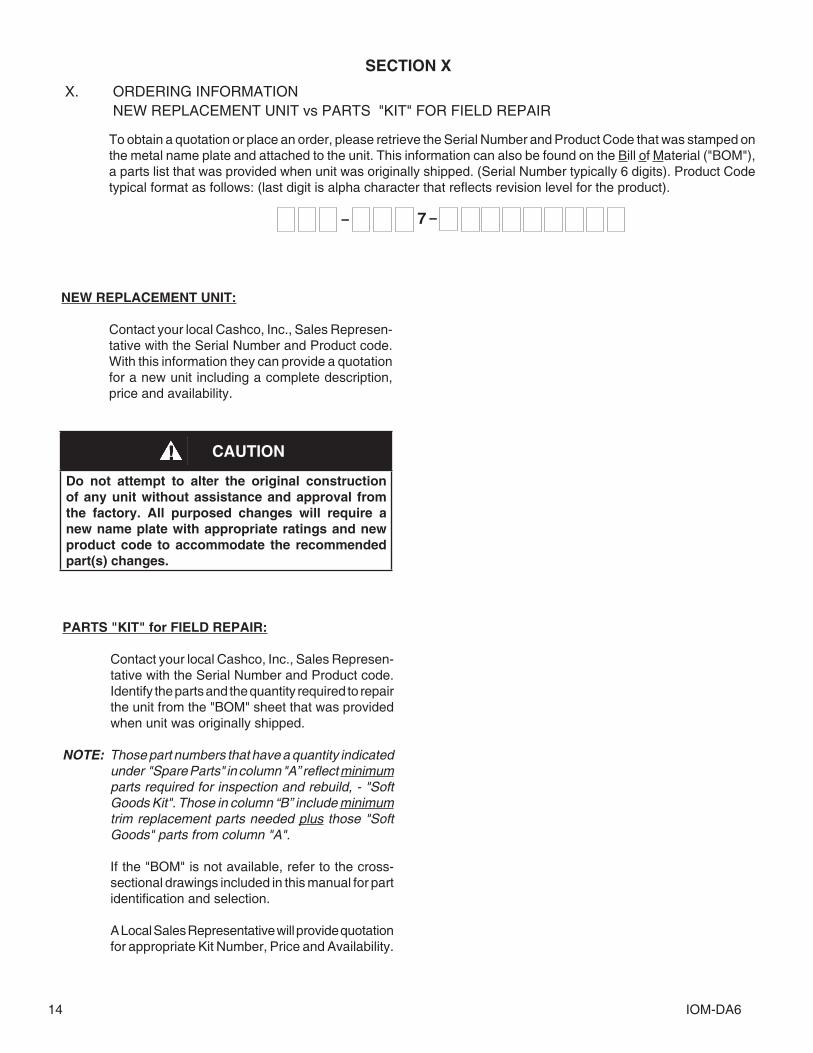
X. ORDERING INFORMATION NEW REPLACEMENT UNIT vs PARTS "KIT" FOR FIELD REPAIR
To obtain a quotation or place an order, please retrieve the Serial Number and Product Code that was stamped on the metal name plate and attached to the unit. This information can also be found on the Bill of Material ("BOM"), a parts list that was provided when unit was originally shipped. (Serial Number typically 6 digits). Product Code typical format as follows: (last digit is alpha character that reflects revision level for the product).
PARTS "KIT" for FIELD REPAIR:
Contact your local Cashco, Inc., Sales Rep re sen- ta tive with the Serial Number and Product code. Identify the parts and the quantity required to repair the unit from the "BOM" sheet that was provided when unit was originally shipped.
NOTE: Those part numbers that have a quantity indicated under "Spare Parts" in column "A” reflect minimum parts required for inspection and rebuild, - "Soft Goods Kit". Those in column “B” include minimum trim replacement parts needed plus those "Soft Goods" parts from column "A".
If the "BOM" is not available, refer to the cross-sectional drawings included in this manual for part identification and selection.
A Local Sales Representative will provide quotation for appropriate Kit Number, Price and Availability.
CAUTION
Do not attempt to alter the original construction of any unit without assistance and approval from the factory. All purposed changes will require a new name plate with appropriate ratings and new product code to accommodate the recommended part(s) changes.

IOM-DA6 15
* Not required on 2" CS & SST Body Material.See Figures 2 – 6 for alternate plug constructions.‡‡ Recommended Repair PartsFor sizes 2-1/2" thru 4", see diaphragm/plug construction in Figure 6.
Item No. Description 7 Diaphragm Cap Screw or Diaphragm Lock Nut 8 Upper Diaphragm Pressure Plate 9 ‡‡ Diaphragm 9.1 Diaphragm (Material #1) 9.2 Diaphragm (Material #2) 9.9 Diaphragm TFE Cover 10 Lower Diaphragm Pusher Plate 11 Flange Bolts 12 * Flange Bolting Nuts 14 ‡‡ Stem Seal 14.1 Upper Stem Seal 14.2 Middle Stem Seal 15 ‡‡ Cage Seal 18 Cage Cap Screws 19 Cage 20 Valve Plug 21 ‡‡ Lower Cage Gasket
Item No. Description 23 Body 24 Lower Guide Bushing 25 Cover Dome 26 Tap Plug (Not Shown) 27 ‡‡ Dynamic Side Seal 27.1 TFE Cap Seal 27.2 O-ring Energizer/Seal 27.3 U-cup with Metal Energizer 27.5 Piston Ring Seal 27.6 Piston Ring Energizer 28 ‡‡ Seat Disc 29 Seat Disc Washer 30 Seat Disc Nut 32 Internal Sensing Plug (External Sensing Only) 33 Internal Sensing Drilled Plug (Internal Sensing Only) 99 Nameplate– ˇ ˇ
Model DA6Composition Diaphragm
FTO – Reverse Flow Direction
The contents of this publication are presented for informational purposes only, and while every effort has been made to ensure their accuracy, they are not to be construed as warranties or guarantees, express or implied, regarding the products or services described herein or their use or applicability. We reserve the right to modify or improve the designs or specifications of such product at any time without notice.Cashco, Inc. does not assume responsibility for the selection, use or maintenance of any product. Responsibility for proper selection, use and maintenance of any Cashco, Inc. product remains solely with the purchaser.

IOM-DA616
Item No. Description 7 Diaphragm Lock Nut 8 Upper Diaphragm Pressure Plate 9 ‡‡ Diaphragm 9.1 Diaphragm (Material #1) 9.2 Diaphragm (Material #2) 9.9 Diaphragm TFE Cover 10 Lower Diaphragm Pusher Plate 11 Flange Bolts 12 * Flange Bolting Nuts 14 ‡‡ Stem Seal 14.2 Middle Stem Seal 14.4 Lower Pusher Plate Gasket 15 ‡‡ Cage Seal 18 Cage Cap Screws 19 Cage 20 Valve Plug 21 ‡‡ Seat Ring 23 Body
Item No. Description 24 Lower Guide Bushing 25 Cover Dome 26 Tap Plug 27 ‡‡ Dynamic Side Seal 27.1 TFE Cap Seal 27.2 O-ring Energizer/Seal 27.3 U-cup with Metal Energizer 27.4 O-ring Seal 27.5 Piston Ring Seal 27.6 Piston Ring Energizer 28 ‡‡ Seat Disc 29 Seat Disc Washer 30 Seat Disc Nut 32 Internal Sensing Plug (External Sensing Only) 33 Internal Sensing Drilled Plug (Internal Sensing Only) 37 Diaphragm Gasket 99 Name Plate
* Not required on 2" CS & SST Body Material.See Figures 2 – 6 for alternate plug constructions.‡‡ Recommended Repair Parts
Model DA6Metal Diaphragm
FTC – Standard Flow Direction

IOM-DA6 17
ATEX 94/9/EC: Explosive Atmospheres and Cashco Inc. Regulators
These valves satisfy the safety conditions according to EN 13463-1 and EN 13463-5 for equipment group IIG 2 c.
Caution: Because the actual maximum temperature depends not on the equipment itself, but upon the fluid temperature, a single temperature class or temperature cannot be marked by the manufacturer.
Specific Precaution to Installer: Electrical grounding of valve must occur to minimize risk of effective electrical discharges.
Specific Precaution to Installer: Atmosphere vent holes should be plugged to further minimize the risk of explosion.
Specific Precaution to Maintenance: The Valve Body/ Housing must be regularly cleaned to prevent buildup of dust deposits.
Specific Precaution to Maintenance: Conduct periodic Continuity Check between Valve Body/ Housing and Tank to minimize risk of electrical discharges.
Attention: When repairing or altering explosion-protected equipment, national regulations must be adhered to. For maintenance and repairs involving parts, use only manufacturer's original parts.
ATEX requires that all components and equipment be evaluated. Cashco pressure regulators are considered components. Based on the ATEX Directive, Cashco considers the location where the pressure regulators are installed to be classified Equipment-group II, Category 3 because flammable gases would only be present for a short period of time in the event of a leak. It is possible that the location could be classified Equipment-group II, Category 2 if a leak is likely to occur. Please note that the system owner, not Cashco, is responsible for determining the classification of a particular installation.
Product Assessment
Cashco performed a conformity assessment and risk analysis of its pressure regulator and control valve models and their common options, with respect to the Essential Health and Safety Requirements in Annex II of the ATEX directive. The details of the assessment in terms of the individual Essential Health and Safety Requirements, are listed in Table 1. Table 2 lists all of the models and options that were evaluated and along with their evaluation.
Models and options not listed in Table 2 should be assumed to not have been evaluated and therefore should not be selected for use in a potentially explosive environment until they have been evaluated.
Standard default options for each listed model were evaluated even if they were not explicitly listed as a separate option in the table. Not all options listed in the tables are available to all models listed in the tables. Individual TB’s must be referenced for actual options.
When specifying a regulator that is to be used in a potentially explosive environment one must review the evaluations in Table 1 and 2 for the specific model and each and every option that is being specified, in order to determine the complete assessment for the unit.
A summary of the models and options found to have an impact on ATEX assessment due to potential ignition sources or other concerns from the ATEX Essential Health and Safety Requirements, are listed below.
1. The plastic knob used as standard on some models, (P1, P2, P3, P4, P5, P7, 3381, 4381, 1171, and 2171) is a potential ignition source due to static electricity. To demonstrate otherwise, the knob must be tested to determine if a transferred charge is below the acceptable values in IEC 60079-0 Section 26.14 (See items 25, 27, and 28 in Appendix A). Until the plastic knob has been shown to be acceptable, then either the metal knob option, or a preset outlet pressure option is required to eliminate this ignition source (See items 45 and 64 in Tables).
2. The pressure gauges offered as options on a few of the regulator models (DA’s, P1-7, D, 764, 521), use a plastic polycarbonate window that is a potential ignition source due to static electricity. To demonstrate that the gauges are not a potential source of ignition, the gauges would need to be tested to determine if a transferred charge is below
NOTICE
Only for Product Codes wherein hazard category ATEX has been selected.

IOM-DA618
indicating the gauge is compliant with the ATEX Directive (See items 26, 27, and 28 in Appendix A). Until compliance is determined, regulators should not be ordered with pressure gauges for use in potentially explosive environments.
3. Tied diaphragm regulators with outlet ranges greater than 100 psig should be preset to minimize the risk that improper operation might lead to an outboard leak and a potentially explosive atmosphere (See item 6 in Table 1).
4. Regulators must be ordered with the non-relieving option (instead of the self-relieving option) if the process gas they are to be used with is hazardous (flammable, toxic, etc.). The self-relieving option vents process gas through the regulator cap directly into the atmosphere while the non-relieving option does not. Using regulator with the self- relieving option in a flammable gas system could create an explosive atmosphere in the vicinity of the regulator.
5. Regulators with customer supplied parts are to be assumed to not have been evaluated with regard to ATEX and thus are not to be used in a potentially explosive environment unless a documented evaluation for the specific customer supplied parts in question has been made. Refer to Table 1 for all models and options that have been evaluated.
Product Usage
A summary of ATEX related usage issues that were found in the assessment are listed below.
1. Pressure regulators and control valves must be grounded (earthed) to prevent static charge build-up due to the flowing media. The regulator can be grounded through any mounting holes on the body with metal to metal contact or the system piping can be grounded and electrical continuity verified through the body metal seal connections. Grounding of the regulator should follow the same requirements for the piping system. Also see item 30 in Table 1.
2. The system designer and users must take precautions to prevent rapid system pressurization which may raise surface temperatures of system components and tubing due to adiabatic compression of the system gas.
3. Heating systems installed by the user could possibly increase the surface temperature and must be evaluated by the user for compliance with the ATEX Directive. User installation of heating systems applied to the regulator body or system piping that affects the surface temperature of the pressure regulator is outside the scope of this declaration and is the responsibility of the user.
4. The Joule-Thomson effect may cause process gases to rise in temperature as they expand going through a regulator. This could raise the external surface temperature of the regulator body and downstream piping creating a potential source of ignition. Whether the Joule-Thomson effect leads to heating or cooling of the process gas depends on the process gas and the inlet and outlet pressures. The system designer is responsible for determining whether the process gas temperature may rise under any operating conditions. If a process gas temperature rise is possible under operating conditions, then the system designer must investigate whether the regulator body and downstream piping may increase in temperature enough to create a potential source of ignition.
The process gas expansion is typically modeled as a constant enthalpy throttling process for determining the temperature change. A Mollier diagram (Pressure – Enthalpy diagram with constant temperature, density, & entropy contours) or a Temperature – Entropy diagram with constant enthalpy lines, for the process gas, can be used to determine the temperature change. Helium and hydrogen are two gases that typically increase in temperature when expanding across a regulator. Other gases may increase in temperature at sufficiently high pressures.
Product Declaration
If the above issues are addressed by selecting options that do not have potential sources of ignition, avoiding options that have not been assessed, and by taking the proper usage issue precautions, then Cashco regulators can be considered to be a mechanical device that does not have its own source of ignition and thus falls outside the scope of the ATEX directive.
Cashco, Inc.P.O. Box 6 Ellsworth, KS 67439-0006PH (785) 472-4461Fax. # (785) 472-3539www.cashco.comemail: [email protected] in U.S.A. DA6-IOM
Cashco do Brasil, Ltda.Al.Venus, 340Indaiatuba - Sao Paulo, BrazilPH +55 11 99677 7177Fax. No. www.cashco.comemail: [email protected]
Cashco GmbHHandwerkerstrasse 1515366 Hoppegarten, GermanyPH +49 3342 30968 0Fax. No. +49 3342 30968 29www.cashco.comemail: [email protected]