Embed Size (px)
Citation preview

U.S and Foreign Patents & patents pending © Copyright 2008 by Arzel® Zoning Technology, �
Arzel® Zoning Technology, Inc.4801 Commerce Pkwy.Cleveland, OH 44128
Ph: (216) 831-6068 or Toll-Free (800) 611-8312Fax: (216) 831-6074
www.arzelzoning.com
Installation & Operation Instructions
200 MPS Series

U.S and Foreign Patents & patents pending © Copyright 2008 by Arzel® Zoning Technology, �
FEATURES
Control PanelThis Zoning System must be installed by a qualified HVAC Contractor!
Package Contents� pc �00 Series Zone Contol Panel (� or 3 Zone)� pc �4VAC self-resetting transformer� pc Installation Instructions
WHEN INSTALLING THIS PRODUCT...
�. Read these instructions carefully. Failure to follow them could damage the Arzel® Zoning System and/or cause a hazardous condition.
�. Disconnect power supply to the HVAC system and the Arzel® system before making any wiring connections to prevent danger, electrical shock, and equipment damage. 3. The Arzel® System is designed for indoor use only.
4. You must touch a grounded metal object before handling the Arzel® Control Panel to avoid potential loss of internal programs, due to electrostatic discharge.
5. Install in ambient temperature between 40° and �50°F, in a non-condensing area.
6. Complete the Commissioning Checks (p. 8) after installation is complete.
7. The Arzel® Zoning System controls the HVAC equipment via a set of dry-contact relays. Be sure that this is compatible with the equipment operating specifications.
8. All wiring must comply with all applicable electrical codes, ordinances, and regulations.
9. Use properly grounded tools. Wear safety glasses and gloveswhendrillingorcuttingsheetmetalducts,fiber glass, or any hard objects.
�0. Panel contains both AC and DC Terminals. See Equipment Notes (pp. 6 and 7) for more details.
��. Leave these instructions with installed system for future use.
�. The Arzel® Zoning System uses a self-contained, low-pressure air pump to actuate dampers.
�. All zones have full-function, single-stage, heating, cooling, and fan capability from all thermostats.
3. All �00 series systems are both furnace and heat pump compatible.
4. Use any standard �4VAC thermostat, Programmable / Non-programmable, auto/manual changeover/Wireless.
5. Built-in heating, cooling, fan priority system.
6. Emergency heat changeover (manual switch or remote outdoor thermostat) for heat pump balance point changeover from heat pump to backup heat functions.
7. Compressor timed off control (delay on break). When the compressor is turned off, it cannot restart for four (4) minutes. This feature allows the refrigerant pressure to balance before restarting.
8. “FAN ON HEAT” switch generates fan call anytime there is a call for heat: typically used with hydronic coils or electric heat.
9. Manual Pump Switch (MPS™) is provided to start the pump manually and open all the zone dampers.
�0. Dampers remain open in the last zone that called for service to take advantage of additional energy savings from blower timed-off cycles that exist on all heating and some cooling equipment.
��. LEDs indicate all system operations.
��. A 40VA, �4VAC, self-resetting, plug-in type transformer is provided to power this �00 series equipment and thermostats.
Available AccessoriesSmartSlave™ Zones
The SmartSlave™ Zone opens its dampers only when the equipment operation is compatible with the slave thermostat request.
Caution - Electrical HazardCan cause personal injury or equipment damage. Disconnect power to all systems before beginning installation.

U.S and Foreign Patents & patents pending © Copyright 2008 by Arzel® Zoning Technology, 3
General Operation Information
THERMOSTATSThe �00 Series™ Arzel® Zone Control™ is compatible with any standard �4VAC thermostat: Wireless, Auto/Manual changeover, Programmable/Non-programmable, Heat/Cool or Fan/Auto/On sub-base switching. If the thermostat has an adjustable heating anticipator (mechanical thermostats), set it to the shortest or lowest setting. Heat pump thermostats are required for heat pump operation. Set up the thermostat to call Y,G in heating: Y,G,O in cooling.
LEAVING AIR TEMPERATURE CONTROLSThe �00 Series™ does not monitor the temperature of the air in the ductwork. If positive control is desired, additional temperature controls must be installed. (The Arzel® AirBoss™ series panels do feature a built-in Leaving Air Temperature sensor.)
SMARTSLAVE™ ZONES (Optional)The SmartSlave™ thermostat does not control the HVAC equipment. It will only open its zone dampers if the HVAC Out-put call is compatible with the thermostat call. Do not use HP (heat pump) thermostats for a SmartSlave™ Zone.
A SmartSlave™ Zone thermostat must have a heating-cooling sub-base switch for “Fan On” (G) to be utilized.Connect R, W, Y, G thermostat terminals to the corresponding terminals on the SmartSlave™ Zone PC board.ConnectSmartSlave™ZonedampertubingtotheSmartSlave™Zonesolenoidfittingontopofthepanel.Connect the C wire from the SmartSlave™ thermostat to any zone thermostat C terminal. The HVAC Output “C” terminal MUST be connected to the common terminal of the equipment transformer for proper SmartSlave™ operation.
BYPASSClosing sections of ductwork will increase static pressure in the system. This will allow the system to heat and cool more effectively. Excessive static can create air noise. A bypass damper will relieve execess static pressure and eliminate objectionable air noise. Please refer to the Arzel® Bypass Sizing Chart for guidance on choosing and sizing a bypass system.
Equipment Notes
The mini-pump, located in the bottom of the enclosure, runs anytime there is a call from any thermostat. It creates both pressure and vacuum. On a call from any thermostat, the logic board will energize the solenoid valve(s) for non-calling zone(s) and make the appropriate dry contact relays to start the HVAC equipment.
2 3
1
Dampers open with vacuum. Dampers close with pressure.The logic board is designed for heating to have priority over cooling and cooling to have priority over fan operation.
Whenallthermostatsaresatisfied,theairpumps,theHVACequipment,andthesolenoid air valves are de-energized. Dampers will remain in whatever position theywereinwhenthelastthermostatcallwasfinished.Leavingthedamp-ers open in the last zone served allows the HVAC system to utilize the residual energy in the system at the end of both the heating and cooling cycles.
The Manual Pump Switch (MPS™) is provided to run the pump continuously. Turning the MPS switch to ON manually makes the pump relay and the pump starts, driving all dampers open. This creates a failsafe. If the board fails the dampers can be easily opened and the system run from one thermostat.
1
2
3
U.S and Foreign Patents & patents pending © Copyright 2008 by Arzel® Zoning Technology, 4
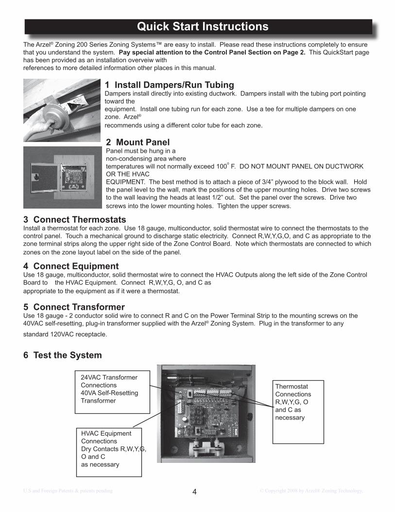
Quick Start InstructionsThe Arzel® Zoning �00 Series Zoning Systems™ are easy to install. Please read these instructions completely to ensure that you understand the system. Pay special attention to the Control Panel Section on Page 2. This QuickStart page has been provided as an installation overveiw with references to more detailed information other places in this manual.
1 Install Dampers/Run Tubing Dampers install directly into existing ductwork. Dampers install with the tubing port pointing toward the equipment. Install one tubing run for each zone. Use a tee for multiple dampers on one zone. Arzel® recommends using a different color tube for each zone.
5 Connect Transformer Use �8 gauge - � conductor solid wire to connect R and C on the Power Terminal Strip to the mounting screws on the40VAC self-resetting, plug-in transformer supplied with the Arzel® Zoning System. Plug in the transformer to any
standard ��0VAC receptacle.
6 Test the System
3 Connect ThermostatsInstall a thermostat for each zone. Use �8 gauge, multiconductor, solid thermostat wire to connect the thermostats to the control panel. Touch a mechanical ground to discharge static electricity. Connect R,W,Y,G,O, and C as appropriate to the zone terminal strips along the upper right side of the Zone Control Board. Note which thermostats are connected to which zones on the zone layout label on the side of the panel.
4 Connect Equipment Use �8 gauge, multiconductor, solid thermostat wire to connect the HVAC Outputs along the left side of the Zone Control Board to the HVAC Equipment. Connect R,W,Y,G, O, and C as appropriate to the equipment as if it were a thermostat.
2 Mount PanelPanel must be hung in a non-condensing area where temperatures will not normally exceed �00o F. DO NOT MOUNT PANEL ON DUCTWORK OR THE HVAC EQUIPMENT. The best method is to attach a piece of 3/4” plywood to the block wall. Hold the panel level to the wall, mark the positions of the upper mounting holes. Drive two screws to the wall leaving the heads at least �/�” out. Set the panel over the screws. Drive two screws into the lower mounting holes. Tighten the upper screws.
Thermostat ConnectionsR,W,Y,G, O and C as necessary
HVAC Equipment ConnectionsDry Contacts R,W,Y,G, O and Cas necessary
�4VAC Transformer Connections40VA Self-Resetting Transformer

U.S and Foreign Patents & patents pending © Copyright 2008 by Arzel® Zoning Technology, 5
Wiring DiagramsThe following diagrams have been provided for your convenience. They represent the most common installation techniques.
If your application does not look like either of these or you need additional help, there are additional diagrams at www.arzelzoning.com or contact technical support at (800) 611-8312.
Pump
Pump and Solenoid connections (factory installed)
Zone � Zone � Zone 3
R W
Y G
O B
CH
VAC
Out
puts
�4V
AC
R
C
Rem
ote
OD
T
Pump � � 3 +
ONMPSOFF
�4VACTransformerFurnace/Fan
Center
R W Y G O C
�8-4 or �8-5Thermostat wire
Zone �Thermostat
R W Y G O C
Zone �Thermostat
Zone 3Thermostat
Pump
Pump and Solenoid connections (factory installed)
Zone � Zone � Zone 3
R W
Y G
O B
CH
VAC
Out
puts
�4V
AC
R
C
Rem
ote
OD
T
Pump � � 3 +
ONMPSOFF
�4VACTransformerHeat Pump
R W Y G O C
�8-5 or �8-6Thermostat wire
Zone �Thermostat
Zone �Thermostat
Zone 3Thermostat
Reversing ValveSelect the HVAC Output O terminal if your reversing valve energizes in cooling,B terminal if it energizes in heating
Choose thermostats that energize the O terminal in cooling
�8-5 Thermostat wire
Outdoor Thermostat
ComN/O
orSPST Relay
ComN/O
Load side Coil side
Connect relay coil toE & C from any single thermostat
Furnace/AC
Heat Pump withElectric Backup
�8-5 Thermostat wire
E C
R W Y G O C R W Y G O C
R W Y G O CR W Y G O C R W Y G O C
R W Y G O CR W Y G O CR W Y G O C
R W Y G O CR W Y G O CR W Y G O C

U.S and Foreign Patents & patents pending © Copyright 2008 by Arzel® Zoning Technology, 6
Circuit Board Layout & Equipment Notes
# Name Description
� PWR On/Off w/LED
The Arzel® System is powered by a 40 VA �4VAC transformer (provided). This switch and the HVAC system equipment power switch must always be in the “OFF” position when connecting wires to any terminals.(See control panel DANGER SECTION.)
� �4VAC Terminals
The Arzel® 40 VA transformer (provided) must be connected to these two terminals.
3 HVAC Output
Terminals
Output to the HVAC equipment is controlled by a set of Dry-Contact Relays. The HVAC “R” signal is turned around and sent out to start the appropriate equipment when called by the Zone Control. The HVAC Output circuit is therefore completely isolated from the Zone Control and thermostat power supply.
R.
W.Y.G.O/B.
C.
Connect hot or + side of HVAC equipment transformer (�4 VAC) to thisterminal.Connect to W� of furnace. (Aux. heat terminal if heat pump is installed.)Connect to compressor contactor.Connect to equipment fan relay.Connect either “O” or “B” to heat pump reversing valve, as required byheat pump manufacturer. Use the “O” signal if the unit reverses in thecooling cycle; the “B” if it reverses in the heating cycle. Connect common side of HVAC equipment transformer (�4 VAC) to thisterminal.
4 Thermostat Terminals
Connect thermostat wires (R,W,Y,G,O, and C) as required for your application. Note which thermostats are connected to which zones. (�4VAC)
5 ODT Terminals
Emergency Heat Changeover terminals (5VDC) “Remote ODT” are used for remote switching by outdoor thermostat. This remote switch (or thermostat) will change heat pump operation to backup heat or fossil fuel. If a heat pump is installed with a fossil fuel furnace (without fossil fuel kit) do not connect the (W) wires from the zone thermostats.
123 4 5
6
9
1516
11
10
�4
7
8
��
�3
�7
LED Display Inset
10
11��

U.S and Foreign Patents & patents pending © Copyright 2008 by Arzel® Zoning Technology, 7
�0 Pump LED LED [PMP (Red)] light is ON anytime the pump is running.
�� Compres-sor
Lock-out LED
Any time the zoning system turns the compressor off, it holds it off for four(4) minutes. This prevents short cycling the compressor.
�� TDOTime Delay
Override
This momentary contact, Time Delay Override switch (TDO), is provided on the PC board to speed the checkout of the zoning system. Before using this TDO switch, you must disconnect the HVAC “R” wire in order to avoid short cycling the equipment. AComp. Lockout LED light will indicate 4 minute compressor lockout condition. [Comp Lockout(Red)]
�3 System Status LEDs
The Display Switch controls what information is displayed on the Service LEDs. By default the LEDs indicate the HVAC Output Signal. It will illuminate the “Out” LED and the ap-propriate service LEDs to indicate the call to the equipment.
�4 Display But-ton Func-
tion
Push the button once, and the system illuminates the Zone � (Z�) LED and shows what the Zone � Thermostat is calling for. Push it again and The Zone � (Z�) LED illuminates and the Display LEDs show what Zone � is call-ing for. Push the button a third time and Zone 3 is displayed. Pushing it a fourth time will return it to the Output display.
The system will revert to displaying the Output signal anytime the button is idle for � minute.
�5 Furnace/Heat Pump
Switch
Switch sets the operational mode for the zoning system. Set the switch for the type of equipment that the zoning system is controlling.
�6 Solenoid Terminals and Pump Terminals
Factory connection for the Zone Solenoids (�4VDC) . Solenoids are energized to provide pressure to close the dampers and de-energized to provide vacuum to open the dampers.Factory connections for the pressure/vacuum pump.(�4VAC) The pump operates only when a ther-mostat calls for a Heat/Cool or Fan operation or when the MPS switch is in the ON position.
�7 MPS Switch MPS™ switch starts pump and opens all zone dampers when Power Switch is OFF.
6 Emer. HT. Switch
Emergency Heat Changeover switch, is used to manually bypass the heat pump and energize the auxiliary heat on a call for service (heat pump application only.)
7 Fan-on-Heat Switch
This switch in the “ON” position will provide automatic fan operation on a call for heating, for electric furnaces, hot water coils, steam coils, etc.
8 S�,S�,S3 Solenoid
LEDsThese LEDs indicate which zones are being served and are opening their dampers. [S�,S�,S3(Red)]
9 Fault Code LEDs
F�,F�,F3
The 3 Fault Code LEDs illuminate when a themostat sends an illegal call. A call is illegal if it is improper for the type of HVAC equipment installed. LED will stay lit until the power switch is cycled.F1 = illegal call on zone 1.F2 = illegal call on zone 2.F3 = illegal call on zone 3. Illegal calls are ignored. The system will continue to operate normally, serving any legal calls. Illegal calls may indicate a thermostat or wiring fault in the affected zone.

U.S and Foreign Patents & patents pending © Copyright 2008 by Arzel® Zoning Technology, 8
IF ALL ELSE FAILS... �. Turn the Arzel® power switch to OFF. �. Disconnect the thermostat wires from any zone and connect them to the HVAC OUTPUT terminals. 3. Turn the MPS™ switch ON, this will open ALL zone dampers.
TheHVACsystemwillworkwithoutthebenefitofthezoningsystem.Theheatingandairconditioningequipmentisnowcontrolledbythatthermostat.Alldamperswillstayopen.IftheHVACsystemdoesnotworkinthisconfiguration,youprobably have a wiring, thermostat or other equipment problem.
Problem Possible Causes Correction
No LEDs lit �- Power Switch OFF�- No �4VAC from transformer
Turn Power Switch to ON.Check Transformer input/output. Replace if ��0V is present w/ no �4vac output.
Dampers not opening or closing
1-Insufficient Pressure/Vacuum �- Binding on rectangular duct
Check for open tube ends or leaky damper actuator.Cutopeningtospecifieddimensionperinstallationmanual.
HVAC system not operating
�- No equipment control power�- Output relay failure
Check equipment transformer and/or control wiringCheck continuity between “R” and calling circuit (W,Y,G) at the HVAC Output, if none and the appropriate output LED is lit, replace board.
One zone not being served
�- Illegal call at panel�- Faulty board component
Check wiring of thermostat to Panel (“O” is energized with cooling call only).If call is legal and no service provided, replace PC board
Slave zone not operating
No Comon wire from equip-ment control transformer
Connect “C” from equipment to “C” of HVAC Output terminals in panel.
Low air flow to zones
1- Bypass Damper Open2- Restriction in system
Adjust weight on bypass damper for maximum static to smallest zone.Check filter, DX-coil, or secondary heat exchanger coil for blockage.
FAN CHECK-OUTSet all thermostats to the OFF position and all fan switches to AUTO.Turn the HVAC system and the Arzel® system PWR switches to ON. The LED light next to the switch will illuminate.Turn the Zone � thermostat fan switch ON. The S� indicator, the Fan output (G) and Pump LED lights will illuminate. The fan in theHVACsystemwillturnon.Thepressureandvacuumpumpwillpositionallthedampers.Checktheairflowatallregisterout-lets to determine that only Zone � dampers are open and all other dampers are closed.Follow the above procedure for all other zones
HEATING & COOLING CHECK-OUTSet all thermostats to the OFF position and all fan switches to AUTO before starting heating system check out.Set Zone � thermostat to the HEAT position and turn thermostat up so that the thermostat is calling for heat. The S� indicator, the W output, and the pump LED lights will illuminate. The pressure/vacuum pump will position all the dampers. Check to see that the heating circuit is energized. If heat pump is installed, check operation of Emergency Back-up heating. Turn the thermostat down untilthethermostatissatisfied.TheLEDlightswillgooutandthepumpwillstop.Damperswillremainopeninthelastzonethatcalled. For heat pump, LED indication will be Y & G.Set thermostat for Zone � to the COOL position. Turn thermostat down so that the thermostat is calling for cooling. The S� indica-tor, the Y and G output and the pump LED will illuminate. The pressure/vacuum pump will position all the dampers. Check to see that the compressor contactor is energized. For heat pump, LED indication will be Y, G & O.Place Zone � thermostat in the OFF position.Follow the above procedure for all other zones.
�.�.3.
4.
�.�.
3.
4.5.
Commissioning Procedure
More tech information is available at: 800-6��-83�� and www.arzelzoning.com
Troubleshooting Matrix