Embed Size (px)
Citation preview
1-800-214-7716 www.midwestair.com
PO Box 5319 281 Hughes Drive Traverse City, MI 49686 Ph:231-941-5865 Fax: 231-941-1636 [email protected]
MIDWEST AIR PRODUCTS CO., INC.
ME-MAN—06
DO NOT STORE GRAY PVC MIST ELIMINATORS IN DIRECT SUNLIGHT
JOB NO:
CUSTOMER:
APPLICATION:
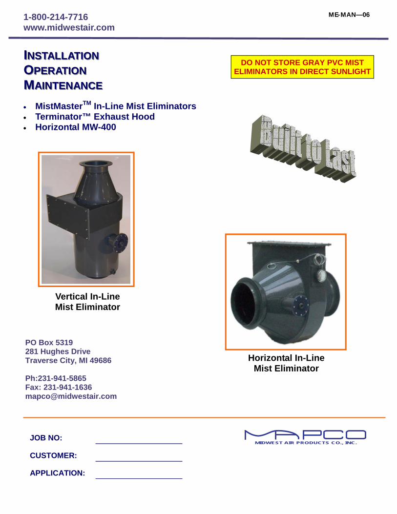
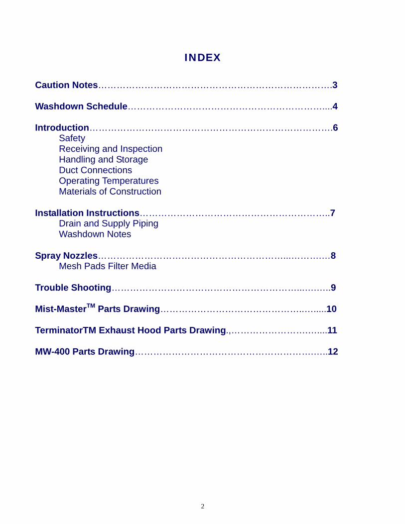
IINSTALLATIONNSTALLATION OOPERATIONPERATION MMAINTENANCEAINTENANCE • MistMasterTM In-Line Mist Eliminators • Terminator™ Exhaust Hood • Horizontal MW-400
Horizontal In-Line Mist Eliminator
Vertical In-Line Mist Eliminator
2
INDEX
Caution Notes………………………………………………………………….3
Washdown Schedule………………………………………………………....4 Introduction…………………………………………………………………….6 Safety Receiving and Inspection Handling and Storage Duct Connections Operating Temperatures Materials of Construction Installation Instructions……………………………………………………..7 Drain and Supply Piping Washdown Notes Spray Nozzles……………………………………………………...……….…8 Mesh Pads Filter Media Trouble Shooting……………………………………………………...….…..9 Mist-MasterTM Parts Drawing………………………………………..….....10 TerminatorTM Exhaust Hood Parts Drawing.,…………………….…....11 MW-400 Parts Drawing………………………………………………….…..12
3
CAUTION
Responsible Personnel must be assigned to the installation, operation and maintenance of this unit. Read complete manual prior to operating this unit. DO NOT WASH FINAL STAGE WITH FAN RUNNING. Observe fan discharge stack immediately after start-up and also on a regular basis thereafter. If excessive misting is present, shut down system immediately and notify MAPCO. Serious damage could occur to property if unit is run under this condition.
Before putting mist eliminator into operation: 1. Check all mesh pads for separation between hood side wall and/or mesh pad retainer. Also
check mesh pad for voids. Any opening or gap in mesh pad could allow mists to bypass mesh pads.
2. Plumbing: Make sure all plumbing is installed to code. Check for leaks. 3. Velocity/CFM: External static pressure for the proposed system may vary depending on ac-
tual field conditions. Make sure exhaust fan is exhausting proper volume (CFM). Deviation from design could cause excessive misting at the mist eliminator.
4. Spray Pattern: Check spray nozzles upon start-up for good spray pattern. Debris lodged in
filter media could become dislodged during transit. Without a filtering device, debris could be-come lodged in spray nozzle causing little or no flow.
Start-Up Service: In addition to this installation, operation and maintenance manual, MAPCO offers a factory trained ser-
vice representative to perform, assist or advise in the installation and start-up of this equipment. The cost for this service is charged per man at the following rates:
A. First eight (8) hours of a single day $50.00/hour B. Overtime hours in a single day $65.00/hour C. Sunday or Holiday $80.00/hour D. Other expenses such as airfare, hotel, car rental, meals, parts, tax, freight, etc. if applicable will be
charged at cost plus 15% administration fee. E. Company Vehicles 1. Company car or truck @ $.50/mile 2. Company truck and trailer @ $1.50/mile Note: MAPCO assumes the "End User" is knowledgeable of this equipment and fully understands the
risks associated with the installation, operation and maintenance of the equipment purchased.
Any malfunction of the mist eliminator should be reported to MAPCO immediately for repair or service instructions.
4
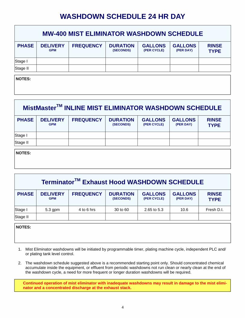
WASHDOWN SCHEDULE 24 HR DAY
1. Mist Eliminator washdowns will be initiated by programmable timer, plating machine cycle, independent PLC and/or plating tank level control.
2. The washdown schedule suggested above is a recommended starting point only. Should concentrated chemical
accumulate inside the equipment, or effluent from periodic washdowns not run clean or nearly clean at the end of the washdown cycle, a need for more frequent or longer duration washdowns will be required.
PHASE DELIVERY GPM
FREQUENCY DURATION (SECONDS)
GALLONS (PER CYCLE)
GALLONS (PER DAY)
RINSE TYPE
Stage I
Stage II
MW-400 MIST ELIMINATOR WASHDOWN SCHEDULE
NOTES:
PHASE DELIVERY GPM
FREQUENCY DURATION (SECONDS)
GALLONS (PER CYCLE)
GALLONS (PER DAY)
RINSE TYPE
Stage I
Stage II
MistMasterTM INLINE MIST ELIMINATOR WASHDOWN SCHEDULE
NOTES:
PHASE DELIVERY GPM
FREQUENCY DURATION (SECONDS)
GALLONS (PER CYCLE)
GALLONS (PER DAY)
RINSE TYPE
Stage I 5.3 gpm 4 to 6 hrs 30 to 60 2.65 to 5.3 10.6 Fresh D.I.
Stage II
TerminatorTM Exhaust Hood WASHDOWN SCHEDULE
NOTES:
Continued operation of mist eliminator with inadequate washdowns may result in damage to the mist elimi-nator and a concentrated discharge at the exhaust stack.
5
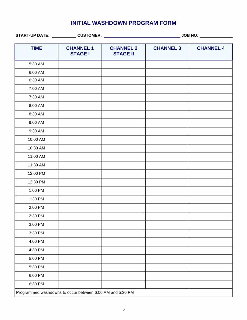
TIME CHANNEL 1 STAGE I
CHANNEL 2 STAGE II
CHANNEL 3 CHANNEL 4
5:30 AM
6:00 AM
6:30 AM
7:00 AM
7:30 AM
8:00 AM
8:30 AM
9:00 AM
9:30 AM
10:00 AM
10:30 AM
11:00 AM
11:30 AM
12:00 PM
12:30 PM
1:00 PM
1:30 PM
2:00 PM
2:30 PM
3:00 PM
3:30 PM
4:00 PM
4:30 PM
5:00 PM
5:30 PM
6:00 PM
6:30 PM
Programmed washdowns to occur between 6:00 AM and 5:30 PM
START-UP DATE: CUSTOMER:
INITIAL WASHDOWN PROGRAM FORM
JOB NO:
6
INTRODUCTION—The performance of every Mist Eliminator depends on many factors. The pur-pose of this manual is to make you aware of these factors so you will obtain the utmost efficient and dependable performance. Providing that proper care is exercised in installing this equipment, and if it is given reasonable main-tenance, you can be assured of trouble free opera-tion. It is important that you study this manual prior to installing this equipment to assure safe installation and operation. SAFETY - The very nature of air handling equip-ment and accessories present a hazard to person-nel during installation and maintenance. The fol-lowing precautions should be observed prior to in-stalling, starting or maintaining this equipment. 1. Inspect the name plates or other tags for spe-
cial instructions. 2. It is recommended that this equipment be in-
stalled by personnel familiar with the installa-tion of this type of equipment.
3. All motors should be locked out until installa-tion is complete. This is accomplished by pad-locking the disconnect switch in the off posi-tion. Inspect the hood interior for debris or loose parts.
4. Inspect ductwork for leakage of harmful or corrosive fumes.
5. Never discharge corrosive or harmful fumes from the fan. The mist eliminator should always be operated with the proper amount of water. Follow good safety practices when installing or maintaining this equipment.
RECEIVING AND INSPECTION - Upon receipt of shipment, check first to see that all items on bill of lading and/or packing slip have been received. By careful inspection determine whether damage has occurred in transit. Any shortage or damage should be noted and a claim should be filed imme-diately. Equipment manufactured by Midwest Air Products Co., Inc. has been inspected at our factory in Traverse City, MI. HANDLING AND STORAGE - If installation of the equipment is delayed and storage is made out-doors, provide reasonable weather protection. When transporting or installing this equipment exercise care to avoid breakage of PVC. Never pick this equipment up by the flanges. DUCT CONNECTIONS - Duct loads can cause distortion with consequent damage. Support duct-work independently of the mist eliminator. OPERATING TEMPERATURES - The mist elimi-nator is fabricated from PVC. When constant tem-perature exceeds 130o F the unit will distort caus-ing severe damage. MATERIALS OF CONSTRUCTION - The mist eliminator body is typically fabricated from 1/8”, 3/16”,1/4" and 3/8” Type I, Grade I corrosion resis-tant, unplasticized PVC. Access doors and re-moval doors are 3/8" thick PVC. It is recommended that all chrome control equip-ment be set up with some form of secondary containment should a leak occur.
7
INSTALLATION INSTRUCTIONS 1. Prior to installation, inspect mesh pads for dam
age during transit. This is accomplished by looking through the inspection door, hood outlet or inlet/outlet with the aid of a flashlight. If media is separated from sidewall, consult factory immediately.
2. Inspect all plumbing connections for breakage
or leaks. 3. If flanges are not drilled, the bolt holes should
be drilled on 4" to 6" centerlines. Use either 1/4" or 3/8" bolts with a flat washer under both bolt head and nut. It is important that a caulk-ing or gasket material which is compatible with the process chemicals be used. Mapco recom-mends the use of an adhesive backed teflon type gasket.
DRAIN AND SUPPLY PIPING - Follow proper plumbing codes when installing plumbing. Double wall containment may be required. DO NOT tap into potable drinking water for supply of clean water. Use the proper back-flow valves, etc. to prevent cross-contamination. 1. The drain is marked with a
tag. It is good practice to install a trap and valve on the drain line. DO NOT reduce the drain line diameter. Unit could overflow and cause dam-age.
2. The supply line should be plumbed using sch.
80 PVC or CPVC as a minimum. DO NOT re-duce the supply line. Reducing supply line could cause higher head pressure and reduced flow. Pipe supports should be installed to in-sure solid installation.
3. In order to minimize plugging of the spray noz-
zles, a filtering device should be installed on the supply line. If not installed, the nozzles will eventually become plugged and cause the mesh pads to plug. This could create undue stress on the mesh pads and allow chemical to bypass the system.
bath contamination, effluent from initial pad wash-downs should be sent to waste treatment until foamy brown traces of oil disappear.
OPERATION IMPORTANT - The polypropylene mesh pads supplied with this unit may contain re-sidual lubricating oil that is used on the knitting needles during pad construction. Mapco knows of no instance where these oils pre-sented a problem involving contamination of the plating bath. To avoid any possibility of plating Inadequate washdown procedures and/ or concen-trations of chemicals may considerably shorten the service life of polypropylene mesh pads. Mapco offers a more expensive alternate mesh pad con-structed of Kynar™. Kynar™ offers a higher de-gree of resistance to chromic acid and should sig-nificantly increase the life expectancy of the first phase pad. These pads are offered as an option and are not standard equipment. Replacement Ky-nar™ mesh pads cost run three to five times that of polypropylene. WASHDOWN SCHEDULE (FREQUENCY AND DURATION) The mist eliminator is designed with one, two or three stages. The first stage will collect the highest percentage of larger chemical droplets and there-fore will require more washdown cycles. The last stage (if so equipped) will require the least amount of washdown cycles. The first stage in most cases will require a wash-down every two to three hours. The duration of the washdown will last from 30 seconds to one minute. This can be determined by visual inspection of the effluent. When the water is clean the washdown duration will be established. The second stage (if so equipped) will require a washdown every three to four hours. The duration of the washdown could last from 10 seconds to one minute. This can be determined by visual in-spection of the effluent. When the water is clean the washdown duration will be established. Proper washdown of the mesh pad will be indi-cated when effluent produced from washdown runs clear at the end of the wash cycle. For situa-tions involving very light loadings, it may be possi-ble to decrease washdown frequency or duration or both. A lightly colored effluent will indicate the need for more frequent or longer duration wash-down of the mesh pad depending on what you plan to do with the effluent..
8
NOTE: Use the appropriate safety equipment, clothing and eye protection. Follow manufactures recommended safety procedures for safe handling of all chemicals and other potential hazards. A. SPRAY NOZZLES Spray nozzles should be checked for proper
spray pattern. The spray pattern should give the appearance of a full cone for each nozzle. If the pattern appears to be erratic, the spray header and nozzle assembly should be re-moved from the unit and cleaned. Improper or no spray can cause severe plugging and dete-rioration of the mesh pads. Mapco recom-mends the use of a strainer in the main header line to minimize nozzle plugging.
1. Shut off water supply to spray header. Follow
proper safety procedures to insure against header discharge while working on spray header.
2. Remove bolts securing header flange to side-
wall of scrubber. Break apart union connection at main spray header. Take all necessary pre-cautions to avoid spillage of solution. Be sure solution has completely drained from header. Pry header away from backing plate.
Exercise caution to avoid breaking header
flange when removing or prying. Remove header from unit.
3. Remove threaded end cap and/or all spray
nozzles from spray header. Remove all debris from nozzles and header.
4. Reverse above steps and re-install. Make sure
header flange and backing plate are secured and leak proof. Mapco recommends the use of a 100% silicone caulking and /or Teflon gasket.
B. MESH PAD FILTER MEDIA Mesh pads should be checked for plugging,
build-up or separation from retainer. Under nor-mal circumstances, the mesh pad filter media requires minimal maintenance, provided, the spray nozzles, washdown schedule, and wash-down concentration are maintained. Other fac-tors that may accelerate plugging are minerals in the washdown liquor such as calcium or small dust particles present in the plant air from grinding operations, etc. Should the unit be operated for periods without water,
or other particles are present in the plant air, the mesh pads will eventually plug and/or deteriorate. If mesh pad becomes plugged, remove and clean immediately. MAPCO recommends at a minimum, bi-annual removal and inspection of the Mist Elimi-nating components. A decreased exhaust volume may indicate plugging of the mesh pad. The mesh pad and pad retainer can be immersed in a rinse tank to remove accumulated deposits. Eventual replacement of the mesh pad may be necessary. Typical 1st stage pad life ranges from two to four years with proper wash down. MAPCO recommends a spare mesh pad and retainer as-sembly be kept on hand.
CAUTION NOTE: Mapco assumes no responsibility or liability for problems resulting from mesh pad replacement by other. Only qualified persons should replace mesh pads when necessary. It is extremely important that the replacement fit as snug as the original.
9
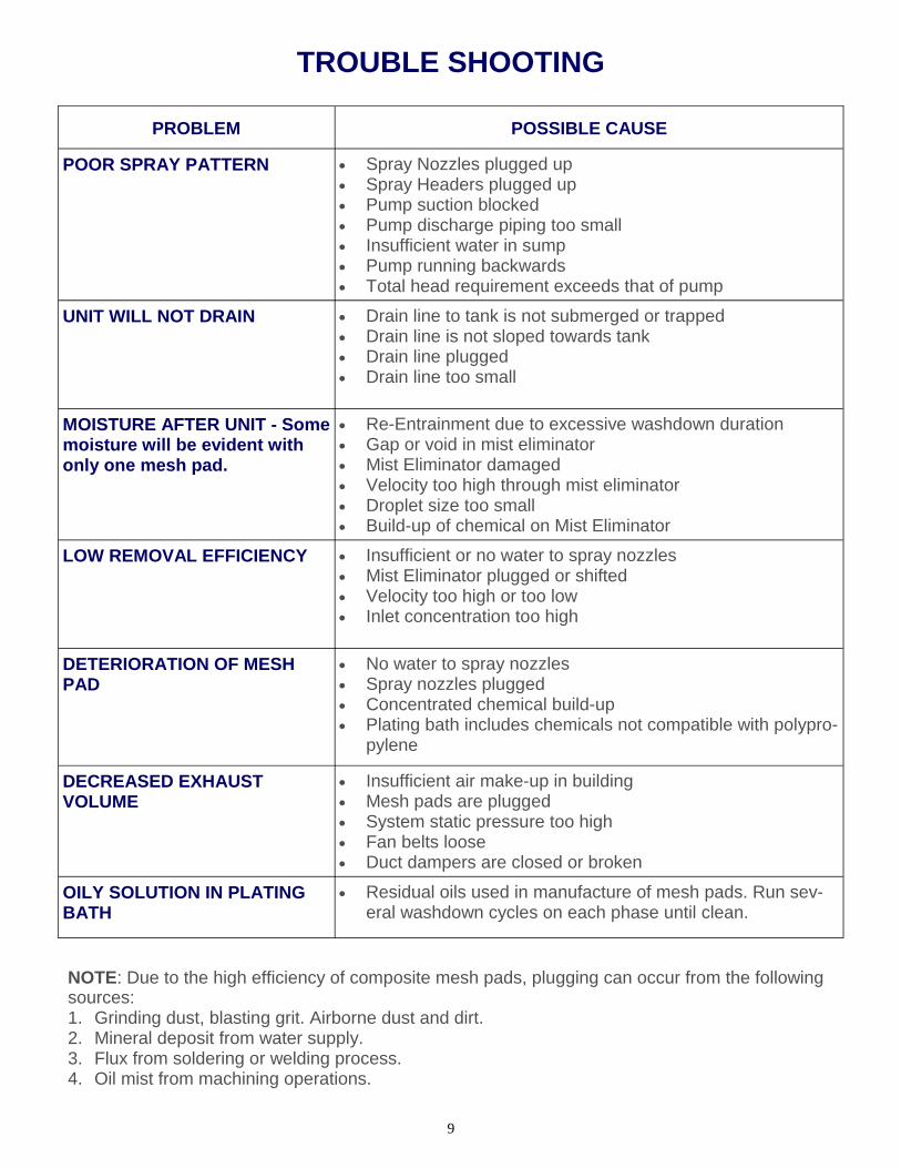
PROBLEM POSSIBLE CAUSE
POOR SPRAY PATTERN • Spray Nozzles plugged up • Spray Headers plugged up • Pump suction blocked • Pump discharge piping too small • Insufficient water in sump • Pump running backwards • Total head requirement exceeds that of pump
UNIT WILL NOT DRAIN • Drain line to tank is not submerged or trapped • Drain line is not sloped towards tank • Drain line plugged • Drain line too small
MOISTURE AFTER UNIT - Some moisture will be evident with only one mesh pad.
• Re-Entrainment due to excessive washdown duration • Gap or void in mist eliminator • Mist Eliminator damaged • Velocity too high through mist eliminator • Droplet size too small • Build-up of chemical on Mist Eliminator
LOW REMOVAL EFFICIENCY • Insufficient or no water to spray nozzles • Mist Eliminator plugged or shifted • Velocity too high or too low • Inlet concentration too high
DETERIORATION OF MESH PAD
• No water to spray nozzles • Spray nozzles plugged • Concentrated chemical build-up • Plating bath includes chemicals not compatible with polypro-
pylene
DECREASED EXHAUST VOLUME
• Insufficient air make-up in building • Mesh pads are plugged • System static pressure too high • Fan belts loose • Duct dampers are closed or broken
OILY SOLUTION IN PLATING BATH
• Residual oils used in manufacture of mesh pads. Run sev-eral washdown cycles on each phase until clean.
TROUBLE SHOOTING
NOTE: Due to the high efficiency of composite mesh pads, plugging can occur from the following sources: 1. Grinding dust, blasting grit. Airborne dust and dirt. 2. Mineral deposit from water supply. 3. Flux from soldering or welding process. 4. Oil mist from machining operations.
10
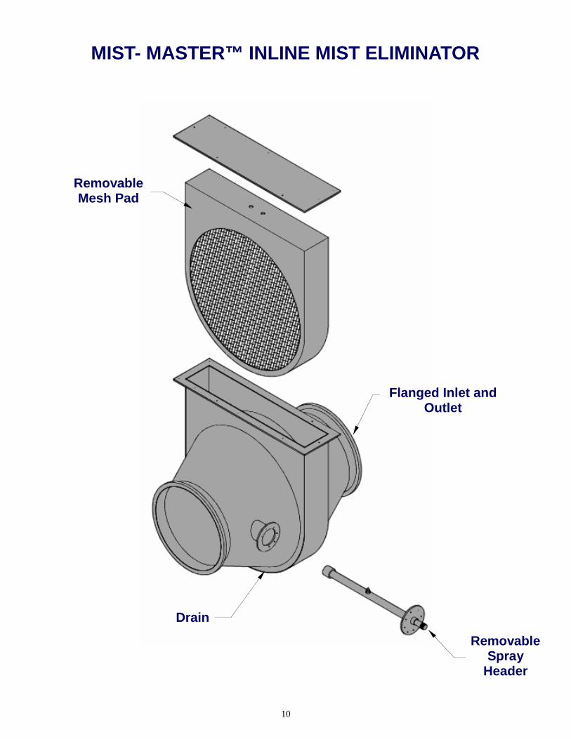
MIST- MASTER™ INLINE MIST ELIMINATOR
Removable Mesh Pad
Removable Spray
Header
Flanged Inlet and Outlet
Drain
11
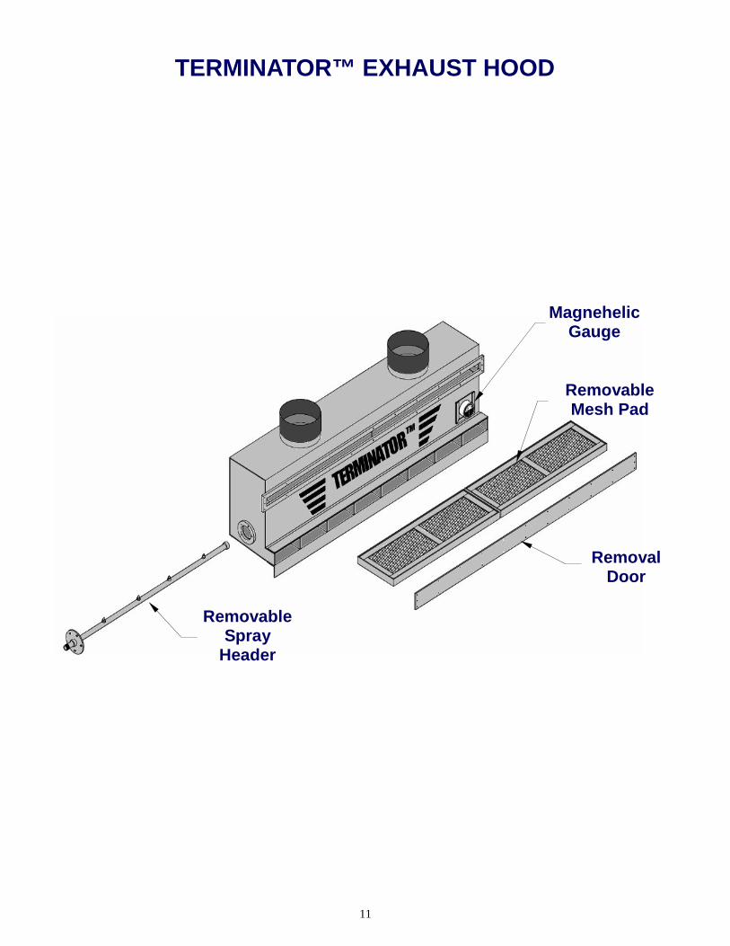
TERMINATOR™ EXHAUST HOOD
Removal Door
Magnehelic Gauge
Removable Spray
Header
Removable Mesh Pad
12
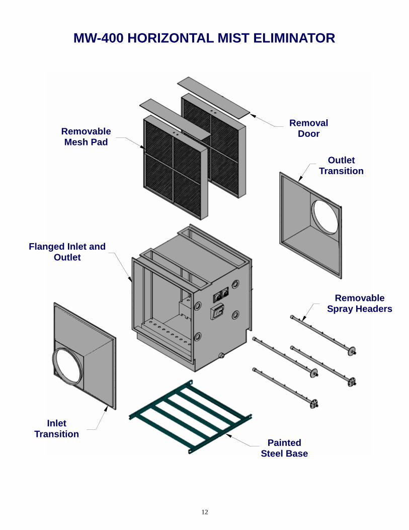
MW-400 HORIZONTAL MIST ELIMINATOR
Removal Door Removable
Mesh Pad
Flanged Inlet and Outlet
Painted Steel Base
Removable Spray Headers
Outlet Transition
Inlet Transition

13
Corrosion Resistant PVC Duct Corrosion Resistant PVC Duct CorzanCorzanTMTM Duct Duct Fiberglass Overlaid DuctFiberglass Overlaid Duct
TurnkeyTurnkey InstallationsInstallations
CorzanCorzanTMTM DuctDuct
TerminatorTerminatorTMTM Composite Mesh PadComposite Mesh Pad
Exhaust HoodsExhaust Hoods
Motorized DampersMotorized Dampers
“and the beat goes on”
Highest Value Exhaust and Pollution
Control Equipment