Embed Size (px)
Citation preview
SAFETY WARNINGOnly qualified personnel should install and service the equipment.The installation, starting up, and servicing of heating, ventilating, and air-
conditioning equipment can be hazardous and requires specific knowledge and training. Improperly installed, adjusted or altered equipment
by an unqualified person could result in death or serious injury.When working on the equipment, observe all precautions in the literature and
on the tags, stickers, and labels that are attached to the equipment.
Midrange Self-Contained Units
Models SCWJ/SCRJ3, 5, 7.5, 10, 12 & 15 tons“A0” and later design sequence
Installation, Operation,
and Maintenance
PKG-SVX14F-ENJanuary 2014

Warnings, Cautions and Notices
Warnings, Cautions and Notices. Note thatwarnings,cautions and notices appear at appropriate intervalsthroughout this manual. Warnings are provided to alertinstalling contractors to potential hazards that could resultin death or personal injury. Cautions are designed to alertpersonnel to hazardous situations that could result inpersonal injury, while notices indicate a situation thatcould result in equipment or property-damage-onlyaccidents.
Your personal safety and the proper operation of thismachine depend upon the strict observance of theseprecautions.
Read this manual thoroughly before operating or servicingthis unit.
Important
Environmental Concerns!
Scientific research has shown that certain man-madechemicals can affect the earth’s naturally occurringstratospheric ozone layer when released to theatmosphere. In particular, several of the identifiedchemicals that may affect the ozone layer are refrigerantsthat contain Chlorine, Fluorine and Carbon (CFCs) andthose containing Hydrogen, Chlorine, Fluorine andCarbon (HCFCs). Not all refrigerants containing thesecompounds have the same potential impact to theenvironment.Trane advocates the responsible handling ofall refrigerants-including industry replacements for CFCssuch as HCFCs and HFCs.
Responsible Refrigerant Practices!
Trane believes that responsible refrigerant practices areimportant to the environment, our customers, and the airconditioning industry. All technicians who handlerefrigerants must be certified.The Federal Clean Air Act(Section 608) sets forth the requirements for handling,reclaiming, recovering and recycling of certainrefrigerants and the equipment that is used in theseservice procedures. In addition, some states ormunicipalities may have additional requirements that
must also be adhered to for responsible management ofrefrigerants. Know the applicable laws and follow them.
ATTENTION: Warnings, Cautions and Notices appear atappropriate sections throughout this literature. Readthese carefully:
WARNINGIndicates a potentially hazardoussituation which, if not avoided, couldresult in death or serious injury.
CAUTIONsIndicates a potentially hazardoussituation which, if not avoided, couldresult in minor or moderate injury. Itcould also be used to alert againstunsafe practices.
NOTICE:Indicates a situation that could result inequipment or property-damage only
WARNING
R-410A Refrigerant under Higher Pressurethan R-22!
The units described in this manual use R-410Arefrigerant which operates at higher pressures than R-22 refrigerant. Use ONLY R-410A rated serviceequipment or components with these units. Forspecific handling concerns with R-410A, please contactyour localTrane representative.Failure to use R-410A rated service equipment orcomponents could result in equipment explodingunder R-410A high pressures which could result indeath, serious injury, or equipment damage.
WARNING
Proper Field Wiring and GroundingRequired!
All field wiring MUST be performed by qualifiedpersonnel. Improperly installed and grounded fieldwiring poses FIRE and ELECTROCUTION hazards.Toavoid these hazards, you MUST follow requirements forfield wiring installation and grounding as described inNEC and your local/state electrical codes. Failure tofollow code could result in death or serious injury.
WARNING
Personal Protective Equipment (PPE)Required!
Installing/servicing this unit could result in exposure toelectrical, mechanical and chemical hazards.
• Before installing/servicing this unit, technicians
MUST put on all Personal Protective Equipment (PPE)
recommended for the work being undertaken.
ALWAYS refer to appropriate MSDS sheets and OSHA
guidelines for proper PPE.
• When working with or around hazardous chemicals,
ALWAYS refer to the appropriate MSDS sheets and
OSHA guidelines for information on allowable
personal exposure levels, proper respiratory
protection and handling recommendations.
• If there is a risk of arc or flash, technicians MUST put
on all Personal Protective Equipment (PPE) in
accordance with NFPA 70E or other country-specific
requirements for arc flash protection, PRIOR to
servicing the unit.
Failure to follow recommendations could result in deathor serious injury.
© 2014Trane All rights reserved PKG-SVX14F-EN
Warnings, Cautions and Notices
Introduction
Overview of Manual
Note: One copy of this document ships inside the controlpanel of each unit and is customer property. It mustbe retained by the unit’s maintenance personnel.
This booklet describes proper installation, operation, andmaintenance procedures for air cooled systems. Bycarefully reviewing the information within this manualand following the instructions, the risk of improperoperation and/or component damage will be minimized. Itis important that periodic maintenance be performed tohelp assure trouble free operation. A maintenanceschedule is provided at the end of this manual. Shouldequipment failure occur, contact a qualified serviceorganizationwithqualified,experiencedHVACtechniciansto properly diagnose and repair this equipment.
Revision Summary
Use this manual for commercial self contained modelsSCWJ and SCRJ. It provides specific installation, ownermaintenance, and diagnostic troubleshooting instructionsfor “AO” and later design sequences.
PKG-SVX14F-EN (03 Jan 2014)
Removed coil resistant coating option from modelnumber description.
PKG-SVX14F-EN (01 Oct 2013)
Updated for increased efficiency project - SCWH to SCWJ.Corrected High pressure disarming and rearming values.Added water volume information.
PKG-SVX14E-EN
Corrected water connection size for SCWH075. Addedperformance testing setup values. Clarified line sizeinformation. Miscellaneous minor corrections.
Trademarks
Trane and theTrane logo are trademarks ofTrane in theUnited States and other countries. All trademarksreferenced in this document are the trademarks of theirrespective owners.
WARNING
Hazardous Voltage!
Disconnect all electric power, including remotedisconnects before servicing. Follow proper lockout/tagout procedures to ensure the power can not beinadvertently energized. Failure to disconnect powerbefore servicing could result in death or serious injury.
WARNING
Hazard of Explosion and Deadly Gases!
Never solder, braze or weld on refrigerant lines or anyunit components that are above atmospheric pressureor where refrigerant may be present. Always removerefrigerant by following the guidelines established bythe EPA Federal Clean Air Act or other state or localcodes as appropriate. After refrigerant removal, use drynitrogen to bring system back to atmospheric pressurebefore opening system for repairs. Mixtures ofrefrigerants and air under pressure may becomecombustible in the presence of an ignition sourceleading to an explosion. Excessive heat from soldering,brazing or welding with refrigerant vapors present canform highly toxic gases and extremely corrosive acids.Failure to follow all proper safe refrigerant handlingpractices could result in death or serious injury.
PKG-SVX14F-EN 3
4 PKG-SVX14F-EN
Table of Contents
Warnings, Cautions and Notices . . . . . . . . . . 2
Introduction . . . . . . . . . . . . . . . . . . . . . . . . . . . 3
Overview of Manual . . . . . . . . . . . . . . . . . . 3
Revision History . . . . . . . . . . . . . . . . . . . . . 3
Model Number Descriptions . . . . . . . . . . . . . . 5
General Data . . . . . . . . . . . . . . . . . . . . . . . . . . . . 6
General . . . . . . . . . . . . . . . . . . . . . . . . . . . . 6
Unit Nameplate . . . . . . . . . . . . . . . . . . . . . 6
Service Equipment and Procedures . . . . . 6
Pre-Installation . . . . . . . . . . . . . . . . . . . . . . . . . 10
Receiving and Handling . . . . . . . . . . . . . . 10
Unit Storage . . . . . . . . . . . . . . . . . . . . . . . 10
Service Access . . . . . . . . . . . . . . . . . . . . . 10
Installation Preparation . . . . . . . . . . . . . . 10
Service Access . . . . . . . . . . . . . . . . . . . . . 11
Proper Lifting Procedure . . . . . . . . . . . . . 13
Dimensions and Weights . . . . . . . . . . . . . . . . 14
Mechanical Requirements . . . . . . . . . . . . . . . 20
Duct Connections . . . . . . . . . . . . . . . . . . . 20
Water Piping . . . . . . . . . . . . . . . . . . . . . . . 20
Refrigerant Piping . . . . . . . . . . . . . . . . . . 20
Brazing Procedures . . . . . . . . . . . . . . . . . 21
Electrical Requirements . . . . . . . . . . . . . . . . . 22
Electrical Data Calculations . . . . . . . . . . . 22
Installation . . . . . . . . . . . . . . . . . . . . . . . . . . . . . 24
Installation Checklist . . . . . . . . . . . . . . . . . . 24
General Unit Requirements . . . . . . . . . . . 24
Fan Discharge Conversion . . . . . . . . . . . . 24
Plenum Installation . . . . . . . . . . . . . . . . . 24
Pre-Start . . . . . . . . . . . . . . . . . . . . . . . . . . . . . . . 25
Pre-Startup Checklist . . . . . . . . . . . . . . . . 25
Water Volumes . . . . . . . . . . . . . . . . . . . . . . . 25
Unit Startup Procedures . . . . . . . . . . . . . . . . . 26
Sequence of Operation . . . . . . . . . . . . . . . . . . 26
Maintenance . . . . . . . . . . . . . . . . . . . . . . . . . . . 27
Cleaning the Condenser Coils . . . . . . . . . 27
Coil Cleaning Procedure . . . . . . . . . . . . . 27
Refrigerant System . . . . . . . . . . . . . . . . . 28
Periodic Checklists . . . . . . . . . . . . . . . . . . .29
Troubleshooting . . . . . . . . . . . . . . . . . . . . . . . . .31
Wiring Diagrams . . . . . . . . . . . . . . . . . . . . . . . .32
PKG-SVX14F-EN 5
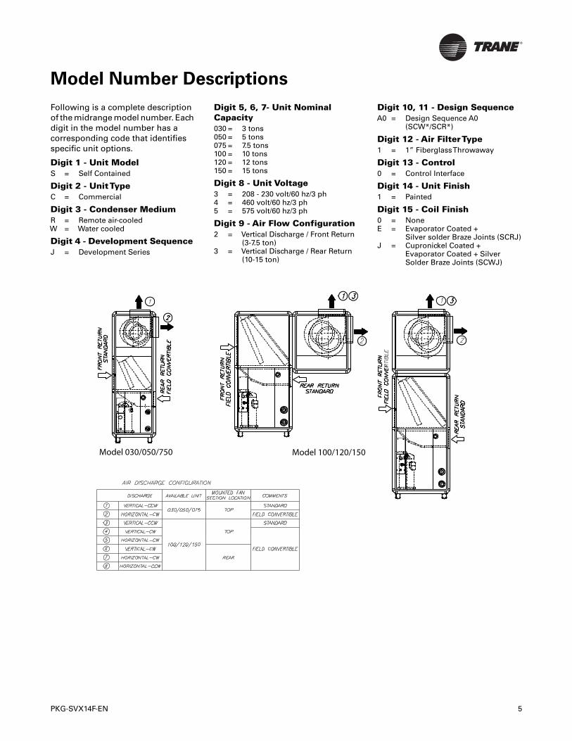
Model Number Descriptions
Following is a complete descriptionof the midrange model number. Eachdigit in the model number has acorresponding code that identifiesspecific unit options.
Digit 1 - Unit ModelS = Self Contained
Digit 2 - UnitTypeC = Commercial
Digit 3 - Condenser MediumR = Remote air-cooledW = Water cooled
Digit 4 - Development SequenceJ = Development Series
Digit 5, 6, 7- Unit NominalCapacity030 = 3 tons050 = 5 tons075 = 7.5 tons100 = 10 tons120 = 12 tons150 = 15 tons
Digit 8 - Unit Voltage3 = 208 - 230 volt/60 hz/3 ph4 = 460 volt/60 hz/3 ph5 = 575 volt/60 hz/3 ph
Digit 9 - Air Flow Configuration2 = Vertical Discharge / Front Return
(3-7.5 ton)3 = Vertical Discharge / Rear Return
(10-15 ton)
Digit 10, 11 - Design SequenceA0 = Design Sequence A0
(SCW*/SCR*)
Digit 12 - Air FilterType1 = 1” FiberglassThrowaway
Digit 13 - Control0 = Control Interface
Digit 14 - Unit Finish1 = Painted
Digit 15 - Coil Finish0 = NoneE = Evaporator Coated +
Silver solder Braze Joints (SCRJ)J = Cupronickel Coated +
Evaporator Coated + SilverSolder Braze Joints (SCWJ)
Model 030/050/750 Model 100/120/150
General Data
General
Midrange models SCWJ/SCRJ are high efficiency, verticalair conditioner units with either front or top dischargeconfiguration options and easy service access. Unitconstruction is heavy gage steel with a baked enamelfinish. Available unit voltages are 208/3/60, 230/3/60, 460/3/60, and 575/3/60.
Refrigeration Circuits
Units are configured in single or double refrigerationcircuits. Each circuit consists of:
• High efficiency scroll compressor mounted on rubberisolation grommets
• Evaporator coils designed for optimum performanceand efficiency with lanced fins and rifled tubing
• Filter-drier
Evaporator Section
The evaporator fan section consists of one or two forwardcurved centrifugal fans powered by a premium efficiencymotor through an adjustable motor sheave and fixeddiameter blower pulley.
Controls
The standard control panel consists of a high voltageterminal block, overload relays for each fan motor,transformer, 3- pole 24-volt contactors for each motor andcompressor, and a 5-second delay timer. Remotethermostat controls are field installed.
Field-Installed Accessories
These items ship separately for field installation:
• Steam coil
• Hot water coil
• Plenum
• Oversized or 2-speed motors
• Remote thermostat
Note: Application of the above options and/oraccessories may require field adjustment of fanspeeds to ensure proper airflow and performance.
Unit Nameplate
Unit nameplate identifies model number, serviceliterature, and wiring diagrams. It is mounted on controlpanel door. Reference this information when makinginquires or ordering parts or literature.
Service Equipment and Procedures
To minimize refrigerant emissions while recoveringrefrigerant, use the manufacturer’s recommendedrecycling equipment per the MSDS. Use equipment andmethods which will pull the lowest possible systemvacuum while recovering and condensing refrigerant.
Equipment capable of pulling a vacuum of less than 1,000microns of mercury is recommended.
Do not open unit to atmosphere for service work untilrefrigerant is fully removed/recovered. When leak-testingwith trace refrigerant and nitrogen, use R-410A. Be awareof any new leak test methods which may eliminaterefrigerants as a trace gas. Perform evacuation prior tocharging with a pump capable of pulling a vacuum of 1,000microns of mercury or less. Let unit stand for 12 hours andverify vacuum does not rise above 2,500 microns mercury.
A rise above 2,500 microns of mercury indicates a leak testis required to locate and repair any leaks. A leak test isrequired on any repaired area.
Charge refrigerant only after verifying equipment does notleak or contain moisture. See Table 1, p. 7 or Table 2, p. 8for proper refrigerant charge values to ensure efficientmachine operation.
When charging is complete, purge or drain charging linesinto an approved refrigerant container. Seal all usedrefrigerant containers with approved closure devices toprevent unused refrigerant from escaping to atmosphere.
Take extra care to properly maintain all service equipmentdirectly supporting refrigerant service work such asgauges, hoses, vacuum pumps, and recycling equipment.
When cleaning system components or parts, avoid usingCFC-11 (R-11) or CFC- 113 (R-113). Use only cleaning-solvents that do not have ozone depletion factors.Properlydispose of used materials. Refrigeration system cleanupmethods using filters and driers are preferred. Check forleaks when excessive purge operation is observed.
Keep abreast of unit enhancements, conversionrefrigerants, compatible parts, and manufacturer’srecommendations that will reduce refrigerant emissionsand increase equipment operating efficiencies.
WARNING
Refrigerant under High Pressure!
System contains oil and refrigerant under highpressure. Recover refrigerant to relieve pressure beforeopening the system. See unit nameplate for refrigeranttype. Do not use non-approved refrigerants, refrigerantsubstitutes, or refrigerant additives. Failure to recoverrefrigerant to relieve pressure or the use of non-approved refrigerants, refrigerant substitutes, orrefrigerant additives could result in an explosion whichcould result in death or serious injury or equipmentdamage.
6 PKG-SVX14F-EN
General Data
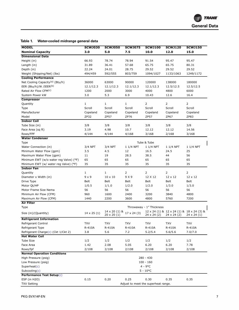
Table 1. Water-cooled midrange general data
MODEL SCWJ030 SCWJ050 SCWJ075 SCWJ100 SCWJ120 SCWJ150Nominal Capacity 3.0 5.0 7.5 10.0 12.0 15.0Dimensional DataHeight (in) 66.93 78.74 78.94 91.54 95.47 95.47Length (in) 31.89 36.41 57.68 65.75 65.75 80.31Depth (in) 22.24 24.01 28.75 29.52 29.52 29.52Weight (Shipping/Net) (lbs) 494/459 592/555 803/759 1094/1027 1133/1063 1249/1172Cooling PerformanceNet Cooling Capacity(a) (Btu/h) 36000 63000 90000 120000 138000 180000EER (Btu/h)/W /IEER(b) 12.1/12.3 12.1/12.3 12.1/12.3 12.1/12.3 12.5/12.5 12.5/12.5Rated Air Flow CFM(c) 1200 2000 3000 4000 4800 6000System Power kW 3.0 5.3 6.9 10.43 12.6 16.4CompressorQuantity 1 1 1 2 2 2Type Scroll Scroll Scroll Scroll Scroll ScrollManufacturer Copeland Copeland Copeland Copeland Copeland CopelandModel ZP32 ZP57 ZP76 ZP57 ZP67 ZP83Indoor CoilTube Size (in) 3/8 3/8 3/8 3/8 3/8 3/8Face Area (sq ft) 3.19 4.98 10.7 12.12 12.12 14.56Rows/FPF 4/144 4/144 4/168 3/168 2/168 3/168Water CondenserType Tube & TubeWater Connection (in) 3/4 NPT 3/4 NPT 1 1/4 NPT 1 1/4 NPT 1 1/4 NPT 1 1/4 NPTMinimum Water Flow (gpm) 3.5 4.5 12 16.5 24.5 25Maximum Water Flow (gpm) 11 19 28.5 38.5 44 56Minimum EWT (w/o water reg Valve) (°F) 65 65 65 65 65 65Minimum EWT (w/ water reg Valve) (°F) 35 35 35 35 35 35Indoor FanQuantity 1 1 2 2 2 2Diameter x Width (in) 9 x 9 10 x 10 9 X 9 12 X 12 12 x 12 12 x 12Drive Type Belt Belt Belt Belt Belt BeltMotor Qt/HP 1/0.5 1/1.0 1/2.0 1/2.0 1/3.0 1/3.0Motor Frame Size Nema 56 56 56 56 56 56Minimum Air Flow (CFM) 960 1600 2400 3200 3840 4800Maximum Air Flow (CFM) 1440 2200 3600 4800 5760 7200Air FilterType Throwaway - 1” Thickness
Size (in)/(Quantity) 14 x 25 (1) 14 x 20 (1) & 20 x 20 (1) 17 x 24 (3) 12 x 24 (1) &
24 x 24 (2)12 x 24 (1) & 24 x 24 (2)
18 x 24 (3) & 24 x 24 (1)
Refrigerant InformationRefrigerant Control TXV TXV TXV TXV TXV TXVRefrigerant Type R-410A R-410A R-410A R-410A R-410A R-410ARefrigerant Charge(c) (Ckt 1/Ckt 2) 3.8 5.6 7.2 5.2/5.4 5.6/5.6 7.0/7.0Hot Water CoilTube Size 1/2 1/2 1/2 1/2 1/2 1/2Face Area 1.42 2.08 5.05 6.20 6.20 7.78Rows/fpf 2/108 2/108 2/108 2/108 2/108 2/108Normal Operation ConditionsHigh Pressure (psig) 280 - 430Low Pressure (psig) 100 - 160Superheat(c) 4 - 9°CSubcooling(c) 5 - 10°CPerformance Test Setup(c)ESP (in H2O) 0.15 0.20 0.25 0.30 0.35 0.35TXV Setting Adjust to meet the superheat range.
PKG-SVX14F-EN 7
General Data
Controls AdjustmentHigh Pressure - Disarming (psig) 610±17 610±17 610±17 610±17 610±17 610±17High Pressure - Rearming (psig) 480±29 480±29 480±29 480±29 480±29 480±29Low Pressure - Disarming (psig) 50±7 50±7 50±7 50±7 50±7 50±7Low Pressure - Rearming (psig) 95±7 95±7 95±7 95±7 95±7 95±7Motor Windings, Thermostat, Std Motor Only - Disarming (psig) - 208-230V Units 266±5 275±5 194±5 194±5 194±5 194±5
Motor Windings, Thermostat, Std Motor Only - Disarming (psig) - 575V Units 266±5 266±5 248±5 248±5 221±5 221±5
Motor Windings, Thermostat, Std Motor Only - Rearming (psig) - 208-230V Units 194±5 198 135 135 135 135
Motor Windings, Thermostat, Std Motor Only - Rearming (psig) - 575V Units 194±5 198 156 156 142 142
(a) Net cooling capacity is rated at 85°F entering water, 80°F entering dry bulb and 67°F entering wet bulb at the rated SCFM air condition.(b) EER and IEER are rated at AHRI conditions.(c) These values are important for performance test setup.
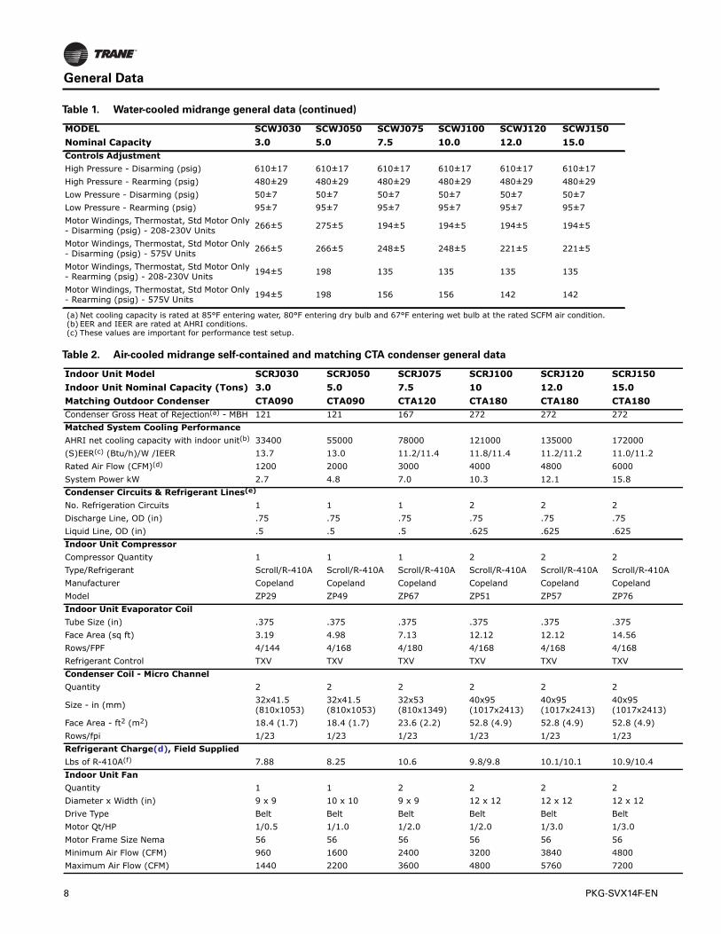
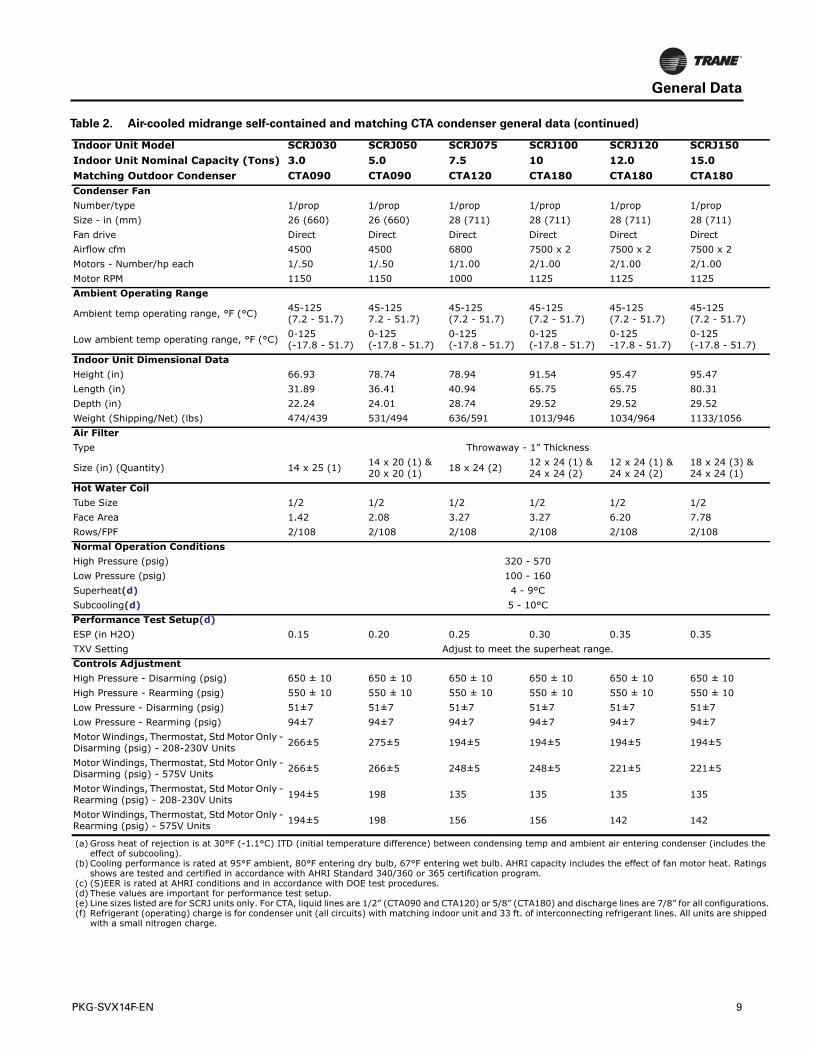
Table 2. Air-cooled midrange self-contained and matching CTA condenser general data
Indoor Unit Model SCRJ030 SCRJ050 SCRJ075 SCRJ100 SCRJ120 SCRJ150Indoor Unit Nominal Capacity (Tons) 3.0 5.0 7.5 10 12.0 15.0Matching Outdoor Condenser CTA090 CTA090 CTA120 CTA180 CTA180 CTA180Condenser Gross Heat of Rejection(a) - MBH 121 121 167 272 272 272Matched System Cooling PerformanceAHRI net cooling capacity with indoor unit(b) 33400 55000 78000 121000 135000 172000(S)EER(c) (Btu/h)/W /IEER 13.7 13.0 11.2/11.4 11.8/11.4 11.2/11.2 11.0/11.2Rated Air Flow (CFM)(d) 1200 2000 3000 4000 4800 6000System Power kW 2.7 4.8 7.0 10.3 12.1 15.8Condenser Circuits & Refrigerant Lines(e)
No. Refrigeration Circuits 1 1 1 2 2 2Discharge Line, OD (in) .75 .75 .75 .75 .75 .75Liquid Line, OD (in) .5 .5 .5 .625 .625 .625Indoor Unit CompressorCompressor Quantity 1 1 1 2 2 2Type/Refrigerant Scroll/R-410A Scroll/R-410A Scroll/R-410A Scroll/R-410A Scroll/R-410A Scroll/R-410AManufacturer Copeland Copeland Copeland Copeland Copeland CopelandModel ZP29 ZP49 ZP67 ZP51 ZP57 ZP76Indoor Unit Evaporator CoilTube Size (in) .375 .375 .375 .375 .375 .375Face Area (sq ft) 3.19 4.98 7.13 12.12 12.12 14.56Rows/FPF 4/144 4/168 4/180 4/168 4/168 4/168Refrigerant Control TXV TXV TXV TXV TXV TXVCondenser Coil - Micro ChannelQuantity 2 2 2 2 2 2
Size - in (mm) 32x41.5 (810x1053)
32x41.5 (810x1053)
32x53 (810x1349)
40x95 (1017x2413)
40x95 (1017x2413)
40x95 (1017x2413)
Face Area - ft2 (m2) 18.4 (1.7) 18.4 (1.7) 23.6 (2.2) 52.8 (4.9) 52.8 (4.9) 52.8 (4.9)Rows/fpi 1/23 1/23 1/23 1/23 1/23 1/23Refrigerant Charge(d), Field SuppliedLbs of R-410A(f) 7.88 8.25 10.6 9.8/9.8 10.1/10.1 10.9/10.4Indoor Unit FanQuantity 1 1 2 2 2 2Diameter x Width (in) 9 x 9 10 x 10 9 x 9 12 x 12 12 x 12 12 x 12Drive Type Belt Belt Belt Belt Belt BeltMotor Qt/HP 1/0.5 1/1.0 1/2.0 1/2.0 1/3.0 1/3.0Motor Frame Size Nema 56 56 56 56 56 56Minimum Air Flow (CFM) 960 1600 2400 3200 3840 4800Maximum Air Flow (CFM) 1440 2200 3600 4800 5760 7200
Table 1. Water-cooled midrange general data (continued)
MODEL SCWJ030 SCWJ050 SCWJ075 SCWJ100 SCWJ120 SCWJ150Nominal Capacity 3.0 5.0 7.5 10.0 12.0 15.0
8 PKG-SVX14F-EN
General Data
he
gs
ns.ed
Condenser FanNumber/type 1/prop 1/prop 1/prop 1/prop 1/prop 1/propSize - in (mm) 26 (660) 26 (660) 28 (711) 28 (711) 28 (711) 28 (711)Fan drive Direct Direct Direct Direct Direct DirectAirflow cfm 4500 4500 6800 7500 x 2 7500 x 2 7500 x 2Motors - Number/hp each 1/.50 1/.50 1/1.00 2/1.00 2/1.00 2/1.00Motor RPM 1150 1150 1000 1125 1125 1125Ambient Operating Range
Ambient temp operating range, °F (°C) 45-125 (7.2 - 51.7)
45-125 7.2 - 51.7)
45-125 (7.2 - 51.7)
45-125 (7.2 - 51.7)
45-125 (7.2 - 51.7)
45-125 (7.2 - 51.7)
Low ambient temp operating range, °F (°C) 0-125 (-17.8 - 51.7)
0-125 (-17.8 - 51.7)
0-125 (-17.8 - 51.7)
0-125 (-17.8 - 51.7)
0-125 -17.8 - 51.7)
0-125 (-17.8 - 51.7)
Indoor Unit Dimensional DataHeight (in) 66.93 78.74 78.94 91.54 95.47 95.47Length (in) 31.89 36.41 40.94 65.75 65.75 80.31Depth (in) 22.24 24.01 28.74 29.52 29.52 29.52Weight (Shipping/Net) (lbs) 474/439 531/494 636/591 1013/946 1034/964 1133/1056Air FilterType Throwaway - 1” Thickness
Size (in) (Quantity) 14 x 25 (1) 14 x 20 (1) & 20 x 20 (1) 18 x 24 (2) 12 x 24 (1) &
24 x 24 (2)12 x 24 (1) & 24 x 24 (2)
18 x 24 (3) & 24 x 24 (1)
Hot Water CoilTube Size 1/2 1/2 1/2 1/2 1/2 1/2Face Area 1.42 2.08 3.27 3.27 6.20 7.78Rows/FPF 2/108 2/108 2/108 2/108 2/108 2/108Normal Operation ConditionsHigh Pressure (psig) 320 - 570Low Pressure (psig) 100 - 160Superheat(d) 4 - 9°CSubcooling(d) 5 - 10°CPerformance Test Setup(d)ESP (in H2O) 0.15 0.20 0.25 0.30 0.35 0.35TXV Setting Adjust to meet the superheat range.Controls AdjustmentHigh Pressure - Disarming (psig) 650 ± 10 650 ± 10 650 ± 10 650 ± 10 650 ± 10 650 ± 10High Pressure - Rearming (psig) 550 ± 10 550 ± 10 550 ± 10 550 ± 10 550 ± 10 550 ± 10Low Pressure - Disarming (psig) 51±7 51±7 51±7 51±7 51±7 51±7Low Pressure - Rearming (psig) 94±7 94±7 94±7 94±7 94±7 94±7Motor Windings, Thermostat, Std Motor Only - Disarming (psig) - 208-230V Units 266±5 275±5 194±5 194±5 194±5 194±5
Motor Windings, Thermostat, Std Motor Only - Disarming (psig) - 575V Units 266±5 266±5 248±5 248±5 221±5 221±5
Motor Windings, Thermostat, Std Motor Only - Rearming (psig) - 208-230V Units 194±5 198 135 135 135 135
Motor Windings, Thermostat, Std Motor Only - Rearming (psig) - 575V Units 194±5 198 156 156 142 142
(a) Gross heat of rejection is at 30°F (-1.1°C) ITD (initial temperature difference) between condensing temp and ambient air entering condenser (includes teffect of subcooling).
(b) Cooling performance is rated at 95°F ambient, 80°F entering dry bulb, 67°F entering wet bulb. AHRI capacity includes the effect of fan motor heat. Ratinshows are tested and certified in accordance with AHRI Standard 340/360 or 365 certification program.
(c) (S)EER is rated at AHRI conditions and in accordance with DOE test procedures.(d) These values are important for performance test setup.(e) Line sizes listed are for SCRJ units only. For CTA, liquid lines are 1/2” (CTA090 and CTA120) or 5/8” (CTA180) and discharge lines are 7/8” for all configuratio(f) Refrigerant (operating) charge is for condenser unit (all circuits) with matching indoor unit and 33 ft. of interconnecting refrigerant lines. All units are shipp
with a small nitrogen charge.
Table 2. Air-cooled midrange self-contained and matching CTA condenser general data (continued)
Indoor Unit Model SCRJ030 SCRJ050 SCRJ075 SCRJ100 SCRJ120 SCRJ150Indoor Unit Nominal Capacity (Tons) 3.0 5.0 7.5 10 12.0 15.0Matching Outdoor Condenser CTA090 CTA090 CTA120 CTA180 CTA180 CTA180
PKG-SVX14F-EN 9
Pre-Installation
Pre-Installation Checklist
Complete the following checklist before beginning unitinstallation.
• Verify unit size and tagging with the unit nameplate.
• Make certain floor or foundation is level, solid, andsufficient to support unit and accessory weights. Levelor repair floor before positioning unit if necessary.
• Allow minimum recommended clearances for routinemaintenance and service. Refer to unit submittals fordimensions.
• Allow three fan diameters above the unit for dischargeductwork. Return air enters the rear of the unit andconditioned supply air discharges through the top.
• Electrical connection knockouts are on the top, left sideof the unit.
• Allow adequate space for piping access and panelremoval. Condenser water piping, refrigerant piping,and condensate drain connections are on the lower leftend panel.
• Electrical supply power must meet specific balanceand voltage requirements as described in the“Electrical Requirements” section.
• Water-cooled units only:The installer is responsible forproviding a condenser main, standby water pump,cooling tower, pressure gauges, strainers, and allcomponents for waterside piping. See “Water Piping”section for general waterside recommendations.
• Air-cooled units only:The installer is responsible forproviding and installing remote air-cooled condenserand refrigerant piping, including filter driers.
Receiving and Handling
Shipping Package
Midrange units ship assembled on skids. Units shipassembled, piped, and charged with either R410a (modelSCWJ) or a dry nitrogen charge (model SCRJ).
Receiving Checklist
Complete the following checklist immediately afterreceiving unit shipment to detect possible shippingdamage.
• Inspect individual cartons before accepting. Check forrattles, bent carton corners, or other visible indicationsof shipping damage.
• If a unit appears damaged, inspect it immediatelybefore accepting the shipment. Make specificnotations concerning the damage on the freight bill.Do not refuse delivery.
• Inspect the unit for concealed damage before it isstored and as soon as possible after delivery. Reportconcealed damage to the freight line within the allotted
time after delivery. Check with the carrier for theirallotted time to submit a claim.
• Do not move damaged material from the receivinglocation. It is the receiver’s responsibility to providereasonable evidence that concealed damage did notoccur after delivery.
• Do not continue unpacking the shipment if it appearsdamaged. Retain all internal packing, cartons, andcrate.Take photos of damaged material if possible.
• Notify the carrier’s terminal of the damageimmediately by phone and mail. Request animmediate joint inspection of the damage by thecarrier and consignee.
• Notify yourTrane representative of the damage andarrange for repair. Have the carrier inspect the damagebefore making any repairs to the unit.
Unit Storage
Take precautions to prevent condensate from forminginside the electrical compartments and motors if the unitis stored before it is installed.
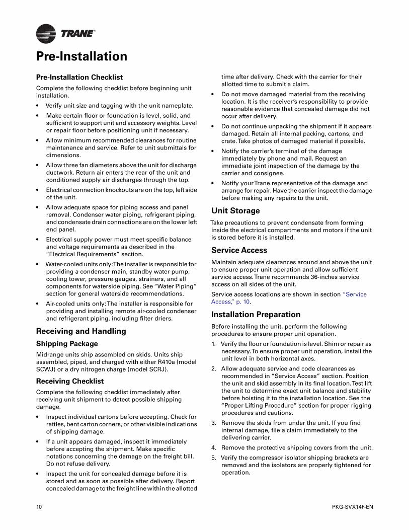
Service Access
Maintain adequate clearances around and above the unitto ensure proper unit operation and allow sufficientservice access.Trane recommends 36-inches serviceaccess on all sides of the unit.
Service access locations are shown in section “ServiceAccess,” p. 10.
Installation Preparation
Before installing the unit, perform the followingprocedures to ensure proper unit operation.
1. Verify the floor or foundation is level. Shim or repair asnecessary.To ensure proper unit operation, install theunit level in both horizontal axes.
2. Allow adequate service and code clearances asrecommended in “Service Access” section. Positionthe unit and skid assembly in its final location.Test liftthe unit to determine exact unit balance and stabilitybefore hoisting it to the installation location. See the“Proper Lifting Procedure” section for proper riggingprocedures and cautions.
3. Remove the skids from under the unit. If you findinternal damage, file a claim immediately to thedelivering carrier.
4. Remove the protective shipping covers from the unit.
5. Verify the compressor isolator shipping brackets areremoved and the isolators are properly tightened foroperation.
10 PKG-SVX14F-EN
Pre-Installation
Service Access
Figure 1. 3 - 7.5 ton SCRJ/SCWJ
LATCH
HEATERACCESS
THIS PANEL GOESTOTOP ONHORI ONTAL AIR DISCHARGECONFIGURATION
PROVIDED DISASSEMBLED(FOR FIELD-INSTALLED REAR RETURN)
Figure 2. 10 - 15 ton SCRJ/SCWJ with top-mounted fan configuration
24
FAN ACCESS
FIELD CONVERTABLEFRONT RETURN
COIL / ELECTRIC HEATERACCESS
MOTOR / DRIVE ACCESS(RIGHT SIDE)
CONTROL BOX &CONDENSER FAN ACCESS
TXV ACCESS(RIGHT SIDE)
26 SERVICE CLEARANCERIGHT SIDE
UNIT-MOUNTEDT-STATOPENING (BOTH SIDES)
POWER ENTRY(BOTH SIDES)
CONTROL ENTRY(BOTH SIDES)
COMPRESSOR ACCESS
42 SERVICE CLEARANCE FRONT
DRAIN CONNECTION
AIR FILTER ACCESS
(BOTH SIDES)
(BOTH SIDES)
26 SERVICE CLEARANCELEFT SIDE
SIGHT GLASS/FILTER DRIER ACCESS(RIGHT SIDE)
24
26 SERVICE CLEARANCELEFT SIDE
STANDARD FACTORY PROVIDEDREAR RETURN
18 SERVICE CLEARANCEREAR
26 SERVICE CLEARANCERIGHT SIDE
NOTE: When front returnis desired, order FrontDecorative Grill inAccessories.
PKG-SVX14F-EN 11
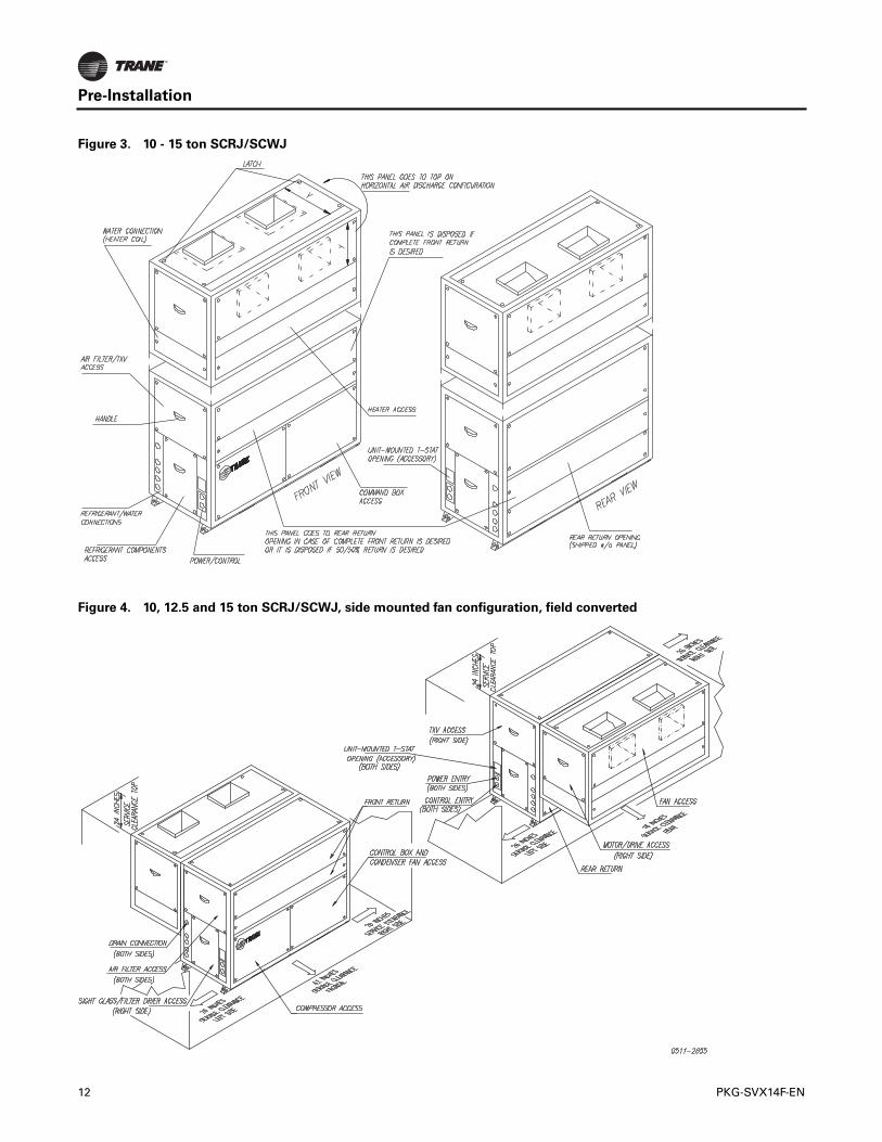
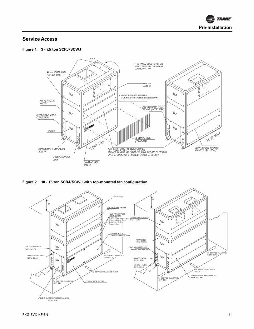
Pre-Installation
Figure 3. 10 - 15 ton SCRJ/SCWJ
Figure 4. 10, 12.5 and 15 ton SCRJ/SCWJ, side mounted fan configuration, field converted
12 PKG-SVX14F-EN
Pre-Installation
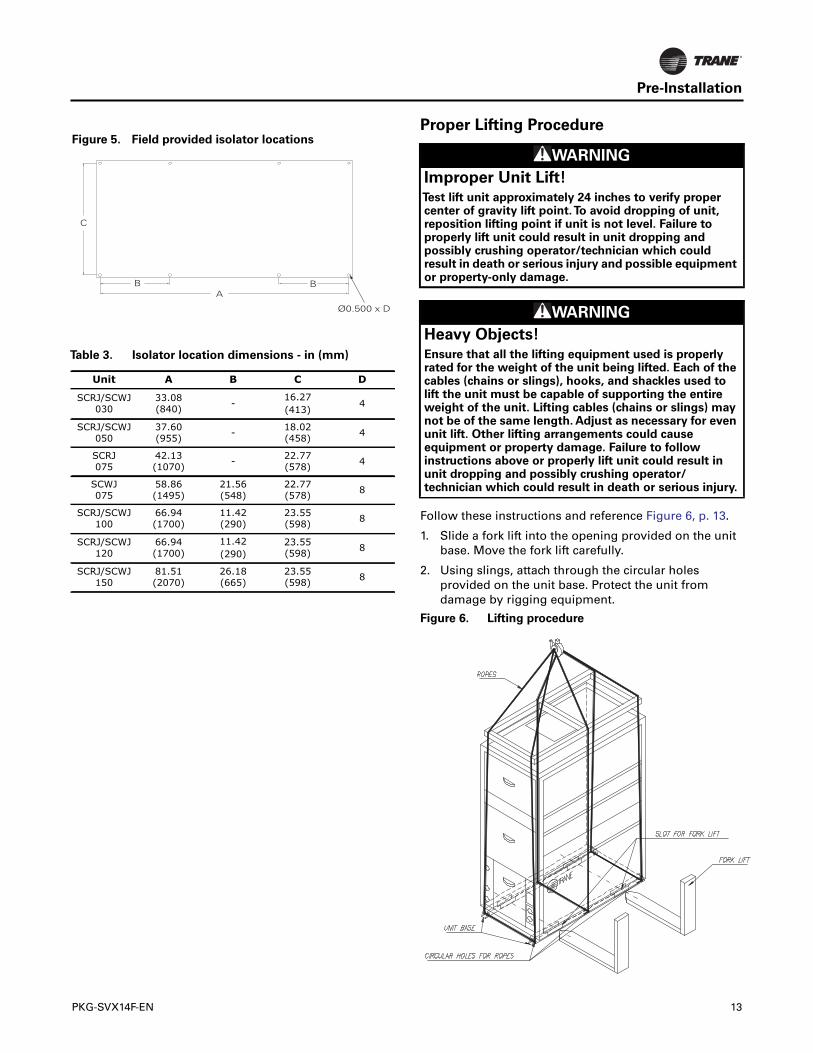
Proper Lifting Procedure
Follow these instructions and reference Figure 6, p. 13.
1. Slide a fork lift into the opening provided on the unitbase. Move the fork lift carefully.
2. Using slings, attach through the circular holesprovided on the unit base. Protect the unit fromdamage by rigging equipment.
Figure 5. Field provided isolator locations
Table 3. Isolator location dimensions - in (mm)
Unit A B C D
SCRJ/SCWJ 030
33.08(840) -
16.27(413)
4
SCRJ/SCWJ 050
37.60(955) - 18.02
(458) 4
SCRJ075
42.13(1070) - 22.77
(578) 4
SCWJ075
58.86(1495)
21.56(548)
22.77(578) 8
SCRJ/SCWJ 100
66.94(1700)
11.42(290)
23.55(598) 8
SCRJ/SCWJ 120
66.94(1700)
11.42(290)
23.55(598) 8
SCRJ/SCWJ 150
81.51(2070)
26.18(665)
23.55(598) 8
Ø0.500 x D
AB B
C
WARNING
Improper Unit Lift!
Test lift unit approximately 24 inches to verify propercenter of gravity lift point.To avoid dropping of unit,reposition lifting point if unit is not level. Failure toproperly lift unit could result in unit dropping andpossibly crushing operator/technician which couldresult in death or serious injury and possible equipmentor property-only damage.
WARNING
Heavy Objects!
Ensure that all the lifting equipment used is properlyrated for the weight of the unit being lifted. Each of thecables (chains or slings), hooks, and shackles used tolift the unit must be capable of supporting the entireweight of the unit. Lifting cables (chains or slings) maynot be of the same length. Adjust as necessary for evenunit lift. Other lifting arrangements could causeequipment or property damage. Failure to followinstructions above or properly lift unit could result inunit dropping and possibly crushing operator/technician which could result in death or serious injury.
Figure 6. Lifting procedure
PKG-SVX14F-EN 13
kg)
ating
9.4)
52)
Dimensions and Weights
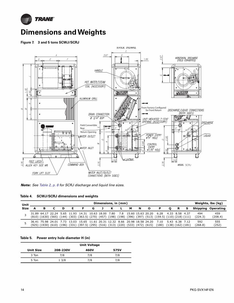
Note: See Table 2, p. 8 for SCRJ discharge and liquid line sizes.
Figure 7. 3 and 5 tons SCWJ/SCRJ
Field ConvertibleRearReturn Opening
From Factory Configuredfor Front Return
SCRJ
Table 4. SCWJ/SCRJ dimensions and weights
Unit Size
Dimensions, in (mm) Weights, lbs (
A B C D E F G J K L M N O P Q R S Shipping Oper
3 31.89 (810)
64.17 (1630)
22.24 (565)
5.65 (144)
11.93 (303)
14.31 (363.5)
10.63 (270)
18.00 (457)
7.80 (198)
7.8 (198)
15.60 (396)
15.63 (397)
20.20 (513)
6.28 (159.5)
4.33 (110)
8.58 (218)
4.37 (111)
494 (224.3)
45(208
5 36.41 (925)
75.98 (1930)
24.01 (610)
7.73 (196)
13.03 (331)
15.65 (397.5)
11.61 (295)
20.31 (516)
12.32 (313)
8.66 (220)
20.98 (533)
18.58 (472)
24.20 (615)
7.10 (180)
5.43 (138)
6.38 (162)
7.12 (181)
592 (268.8)
55(25
Table 5. Power entry hole diameter H (in)
Unit Size
Unit Voltage
208-230V 460V 575V
3 Ton 7/8 7/8 7/8
5 Ton 1 3/8 7/8 7/8
14 PKG-SVX14F-EN
Dimensions and Weights
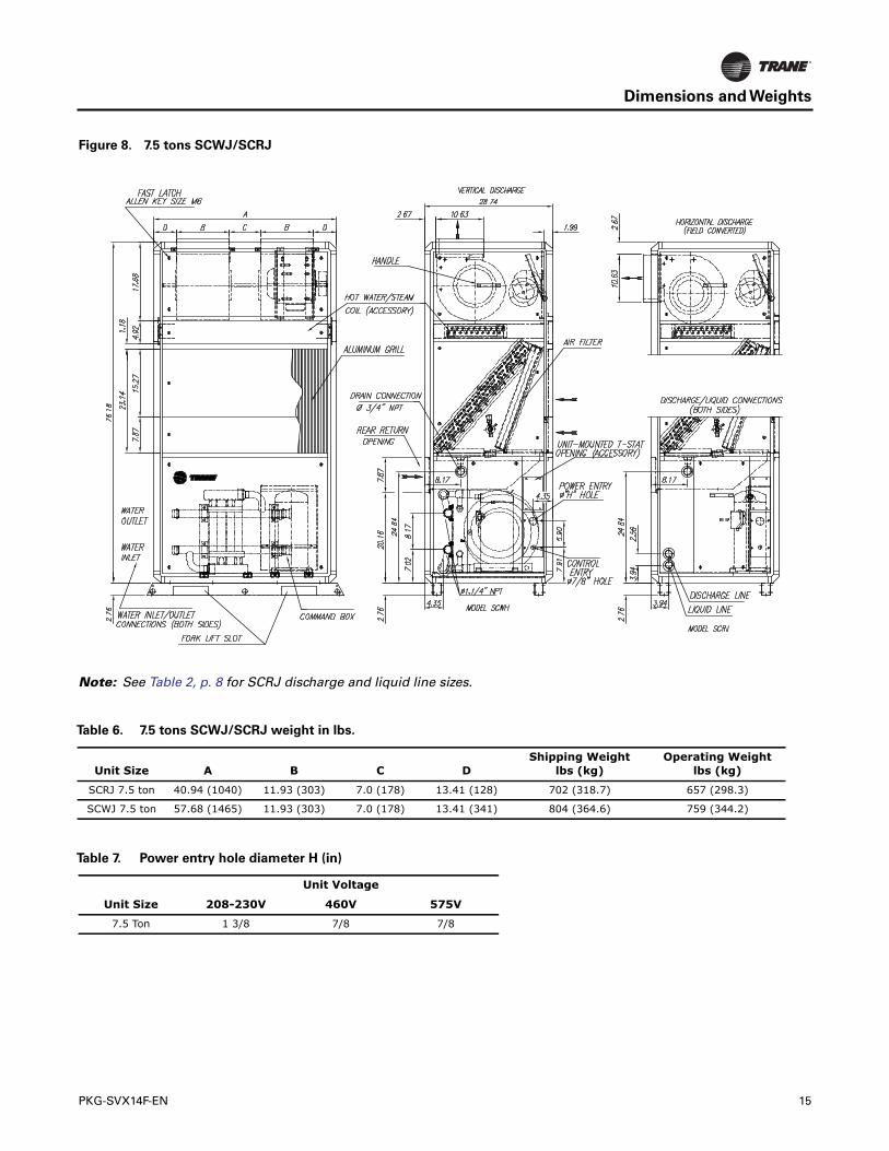
Note: See Table 2, p. 8 for SCRJ discharge and liquid line sizes.
Figure 8. 7.5 tons SCWJ/SCRJ
Table 6. 7.5 tons SCWJ/SCRJ weight in lbs.
Unit Size A B C DShipping Weight
lbs (kg)Operating Weight
lbs (kg)
SCRJ 7.5 ton 40.94 (1040) 11.93 (303) 7.0 (178) 13.41 (128) 702 (318.7) 657 (298.3)
SCWJ 7.5 ton 57.68 (1465) 11.93 (303) 7.0 (178) 13.41 (341) 804 (364.6) 759 (344.2)
Table 7. Power entry hole diameter H (in)
Unit Size
Unit Voltage
208-230V 460V 575V
7.5 Ton 1 3/8 7/8 7/8
PKG-SVX14F-EN 15
Dimensions and Weights
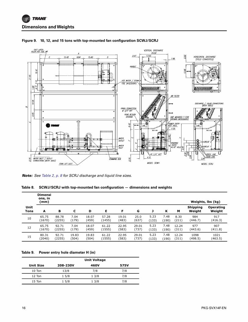
Note: See Table 2, p. 8 for SCRJ discharge and liquid line sizes.
Figure 9. 10, 12, and 15 tons with top-mounted fan configuration SCWJ/SCRJ
Table 8. SCWJ/SCRJ with top-mounted fan configuration — dimensions and weights
Dimensions, in (mm) Weights, lbs (kg)
Unit Tons A B C D E F G J K M
Shipping Weight
Operating Weight
10 65.75(1670)
88.78(2255)
7.04(179)
18.07(459)
57.28(1455)
19.01(483)
25.0(637)
5.23(133)
7.48(190)
8.30(211)
984(446.7)
917(416.3)
12 65.75(1670)
92.71(2255)
7.04(179)
18.07(459)
61.22(1555)
22.95(583)
29.01(737)
5.23(133)
7.48(190)
12.24(311)
977(443.6)
907(411.8)
15 80.31(2040)
92.71(2255)
19.83(504)
19.83(504)
61.22(1555)
22.95(583)
29.01(737)
5.23(133)
7.48(190)
12.24(311)
1098(498.5)
1021(463.5)
Table 9. Power entry hole diameter H (in)
Unit Size
Unit Voltage
208-230V 460V 575V
10 Ton 13/8 7/8 7/8
12 Ton 1 5/8 1 3/8 7/8
15 Ton 1 5/8 1 3/8 7/8
16 PKG-SVX14F-EN
Dimensions and Weights
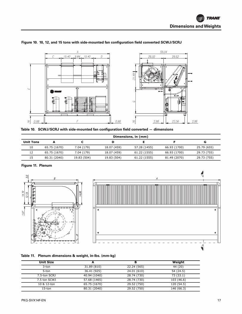
Figure 10. 10, 12, and 15 tons with side-mounted fan configuration field converted SCWJ/SCRJ
Table 10. SCWJ/SCRJ with side-mounted fan configuration field converted — dimensions
Dimensions, in (mm)
Unit Tons A C D E F G
10 65.75 (1670) 7.04 (179) 18.07 (459) 57.28 (1455) 66.93 (1700) 25.79 (655)
12 65.75 (1670) 7.04 (179) 18.07 (459) 61.22 (1555) 66.93 (1700) 29.73 (755)
15 80.31 (2040) 19.83 (504) 19.83 (504) 61.22 (1555) 81.49 (2070) 29.73 (755)
Figure 11. Plenum
Table 11. Plenum dimensions & weight, in-lbs. (mm-kg)
Unit Size A B Weight3-ton 31.89 (810) 22.24 (565) 44 (20)5-ton 36.41 (925) 24.01 (610) 54 (24.5)
7.5-ton SCRJ 40.94 (1040) 28.74 (730) 73 (33.1)7.5 ton SCWJ 57.68 (1465) 28.74 (730) 103 (46.6)10 & 12-ton 65.75 (1670) 29.52 (750) 120 (54.5)
15-ton 80.31 (2040) 29.52 (750) 146 (66.3)
PKG-SVX14F-EN 17
Dimensions and Weights
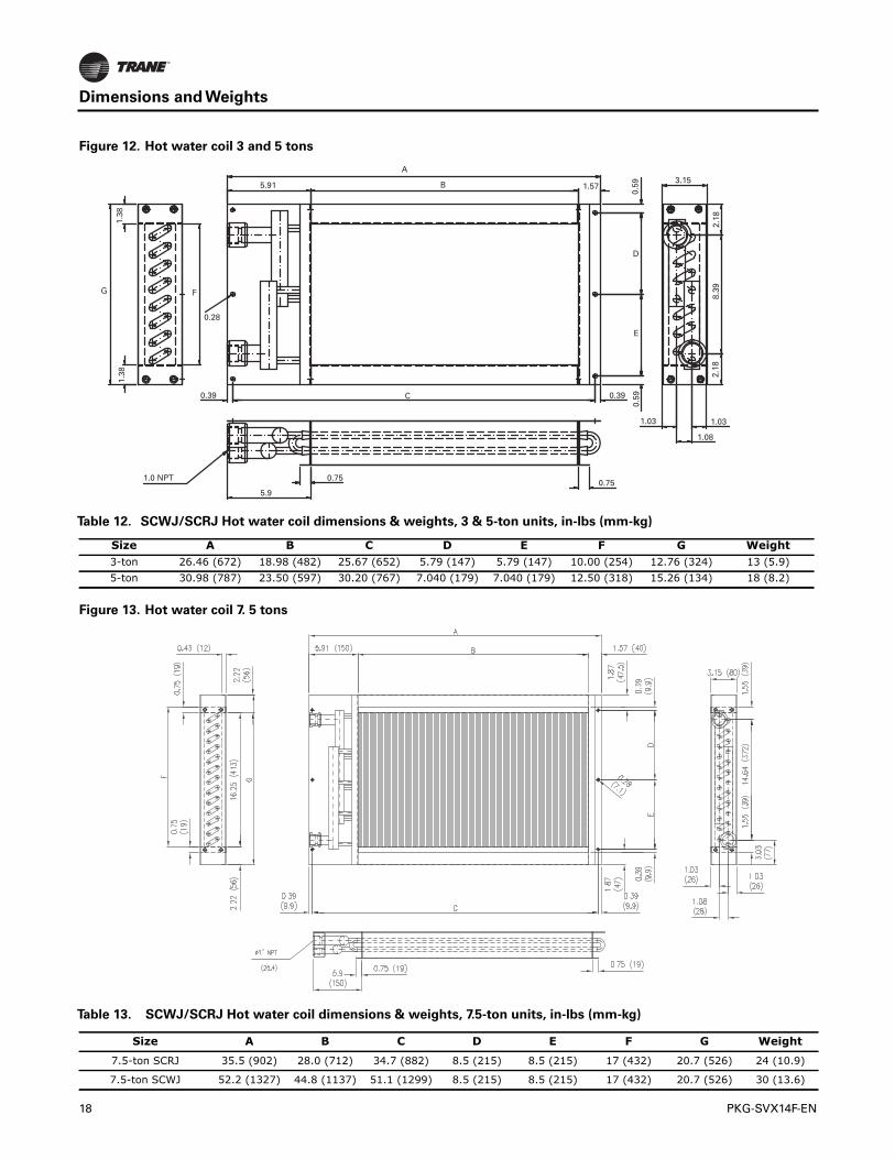
Figure 12. Hot water coil 3 and 5 tons
Table 12. SCWJ/SCRJ Hot water coil dimensions & weights, 3 & 5-ton units, in-lbs (mm-kg)
Size A B C D E F G Weight3-ton 26.46 (672) 18.98 (482) 25.67 (652) 5.79 (147) 5.79 (147) 10.00 (254) 12.76 (324) 13 (5.9)5-ton 30.98 (787) 23.50 (597) 30.20 (767) 7.040 (179) 7.040 (179) 12.50 (318) 15.26 (134) 18 (8.2)
Figure 13. Hot water coil 7. 5 tons
Table 13. SCWJ/SCRJ Hot water coil dimensions & weights, 7.5-ton units, in-lbs (mm-kg)
Size A B C D E F G Weight
7.5-ton SCRJ 35.5 (902) 28.0 (712) 34.7 (882) 8.5 (215) 8.5 (215) 17 (432) 20.7 (526) 24 (10.9)
7.5-ton SCWJ 52.2 (1327) 44.8 (1137) 51.1 (1299) 8.5 (215) 8.5 (215) 17 (432) 20.7 (526) 30 (13.6)
18 PKG-SVX14F-EN
Dimensions and Weights
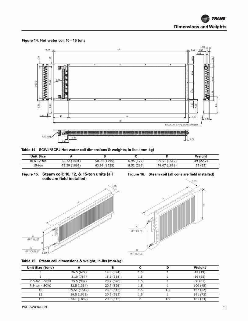
Figure 14. Hot water coil 10 - 15 tons
Table 14. SCWJ/SCRJ Hot water coil dimensions & weights, in-lbs. (mm-kg)
Unit Size A B C D Weight10 & 12-ton 58.72 (1491) 50.98 (1295) 6.95 (177) 59.51 (1512) 49 (22.2)
15-ton 73.29 (1862) 63.98 (1625) 8.52 (216) 74.07 (1881) 55 (25)
Figure 15. Steam coil: 10, 12, & 15-ton units (allcoils are field installed)
A
3.15”
CMPT INLET
DMPT OUTLET
B
6.89”
Figure 16. Steam coil (all coils are field installed)
3.15”
A
B
C
D
MPT INLET
MPT OUTLET
Table 15. Steam coil dimensions & weight, in-lbs (mm-kg)
Unit Size (tons) A B C D Weight3 26.5 (672) 12.8 (324) 1.5 1 42 (19)5 31.0 (787) 15.3 (388) 1.5 1 56 (25)
7.5-ton - SCRJ 35.5 (902) 20.7 (526) 1.5 1 68 (31)7.5-ton - SCWJ 52.5 (1334) 20.7 (526) 1.5 1 100 (45)
10 59.51 (1512) 20.3 (515) 1.5 1.5 137 (62)12 59.5 (1512) 20.3 (515) 1.5 1 161 (73)15 74.1 (1882) 20.3 (515) 2 1.5 161 (73)
PKG-SVX14F-EN 19
Mechanical Requirements
Duct Connections
Install all air ducts according to the National Fire ProtectionAssociation standards for the “Installation of AirConditioning and Ventilation Systems other thanResidenceType (NFPA 90A) and ResidenceType Warm AirHeating and Air Conditioning Systems (NFPA 90B).
Make duct connections to unit with a flexible material suchas heavy canvas. If a fire hazard exists,Trane recommendsusing Flexweave 1000, type FW30 or equivalent canvas.Use three inches for return duct and three inches fordischarge duct. Keep material loose to absorb fanvibration.
Run the ductwork straight from the opening for aminimum of three fan diameters. Do not make abruptturns or transitions near the unit due to increased noiseand excessive static losses. Use elbows with splitters orturning vanes to minimize static losses.
Poorly constructed turning vanes may cause airflowgenerated noise. Check total external static pressuresagainst fan characteristics to be sure required airflow isavailable throughout ductwork.
Water Piping
Condenser Connections
Note: To prevent water damage, install piping drain andvent plugs.
Condenser water piping knockouts are in the lowercorners of both ends of the panel. If necessary, removeinsulation to gain access. All field installed piping mustconform to applicable local, state, and federal codes.
To complete condenser water connections follow theprocedure below.
1. Remove back panel to access water connection fittings.
2. Attach the water supply line to the inlet connection,and the return line to the outlet connection.The waterconnection fittings are copper, so exercise extremecare when connecting steel piping to copper fittings.
3. Ensure that water piping is aligned to the unitconnection fittings. Failure to align piping could causestripped threads, leakage, and possible unit failure.
4. Connection to unit water piping requires a backingwrench to prevent distortion of connecting tubing.Apply backing wrench to water connection points onunit.
Note: NPT connections are female type.
Condensate Drain Connections
Install a water regulating valve in the water supply line tomaintain head pressure when operating with city water ofvarying temperature.
These units require a minimum water pressure of 15 psigand will operate at a maximum of 400 psig.
Provide safeguards against cold weather drain line freeze.
CoolingTower Piping
Cooling tower control affects the unit cycle rates.Condenser water temperature swings from 10-15°F maycause excessive compressor, water valve, and unitcycling. Be sure to set the tower controls to minimizecompressor/ unit cycling.
The cooling tower system requires a separate drain in thewater supply line for service and repair.
WaterTemperature Requirements
Install a water regulating valve in the water supply line tomaintain head pressure when operating with water ofvarying temperature.The valve modulates condenserwater flow to control condensing pressure.The valveopens or closes in response to compressor dischargepressure as sensed by its capillary line connection in theliquid line schrader valve. When the valve is properlyinstalled, water flow automatically decreases as dischargepressure falls and increases as discharge pressure rises.Field installation of the water regulating valve assemblyrequires one valve for each refrigeration circuit.
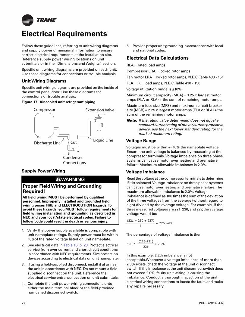
Refrigerant Piping
(Air-Cooled Units Only)
Reference industry recommendations for air-cooled unitrefrigerant piping. If suspending piping from the building,use isolation hangers to prevent vibration transmission.
Air-cooled units ship with a holding charge of nitrogen.Before installing unit piping, momentarily depress eitherthe suction or discharge line access valve to verify that theholding charge has not been lost. If nitrogen does notescape when depressing the access valve, leak test theentire refrigerant system to determine the source of loss.The charge is contained by a continuous loop of both hotgas and liquid lines.You must cut the loop for connectionto discharge and liquid lines. See Figure 17, p. 22.
20 PKG-SVX14F-EN
Mechanical Requirements
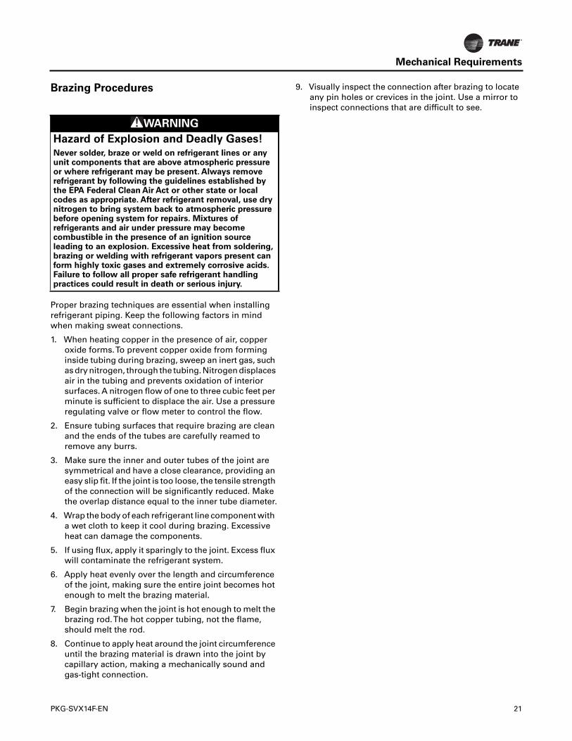
Brazing Procedures
Proper brazing techniques are essential when installingrefrigerant piping. Keep the following factors in mindwhen making sweat connections.
1. When heating copper in the presence of air, copperoxide forms.To prevent copper oxide from forminginside tubing during brazing, sweep an inert gas, suchas dry nitrogen, through the tubing. Nitrogen displacesair in the tubing and prevents oxidation of interiorsurfaces. A nitrogen flow of one to three cubic feet perminute is sufficient to displace the air. Use a pressureregulating valve or flow meter to control the flow.
2. Ensure tubing surfaces that require brazing are cleanand the ends of the tubes are carefully reamed toremove any burrs.
3. Make sure the inner and outer tubes of the joint aresymmetrical and have a close clearance, providing aneasy slip fit. If the joint is too loose, the tensile strengthof the connection will be significantly reduced. Makethe overlap distance equal to the inner tube diameter.
4. Wrap the body of each refrigerant line component witha wet cloth to keep it cool during brazing. Excessiveheat can damage the components.
5. If using flux, apply it sparingly to the joint. Excess fluxwill contaminate the refrigerant system.
6. Apply heat evenly over the length and circumferenceof the joint, making sure the entire joint becomes hotenough to melt the brazing material.
7. Begin brazing when the joint is hot enough to melt thebrazing rod.The hot copper tubing, not the flame,should melt the rod.
8. Continue to apply heat around the joint circumferenceuntil the brazing material is drawn into the joint bycapillary action, making a mechanically sound andgas-tight connection.
9. Visually inspect the connection after brazing to locateany pin holes or crevices in the joint. Use a mirror toinspect connections that are difficult to see.
WARNING
Hazard of Explosion and Deadly Gases!
Never solder, braze or weld on refrigerant lines or anyunit components that are above atmospheric pressureor where refrigerant may be present. Always removerefrigerant by following the guidelines established bythe EPA Federal Clean Air Act or other state or localcodes as appropriate. After refrigerant removal, use drynitrogen to bring system back to atmospheric pressurebefore opening system for repairs. Mixtures ofrefrigerants and air under pressure may becomecombustible in the presence of an ignition sourceleading to an explosion. Excessive heat from soldering,brazing or welding with refrigerant vapors present canform highly toxic gases and extremely corrosive acids.Failure to follow all proper safe refrigerant handlingpractices could result in death or serious injury.
PKG-SVX14F-EN 21
Electrical Requirements
Follow these guidelines, referring to unit wiring diagramsand supply power dimensional information to ensurecorrect electrical requirements at the installation site.Reference supply power wiring locations on unitsubmittals or in the “Dimensions and Weights” section.
Specific unit wiring diagrams are provided on each unit.Use these diagrams for connections or trouble analysis.
Unit Wiring Diagrams
Specific unit wiring diagrams are provided on the inside ofthe control panel door. Use these diagrams forconnections or trouble analysis.
Supply Power Wiring
1. Verify the power supply available is compatible withunit nameplate ratings. Supply power must be within10%of the rated voltage listed on unit nameplate.
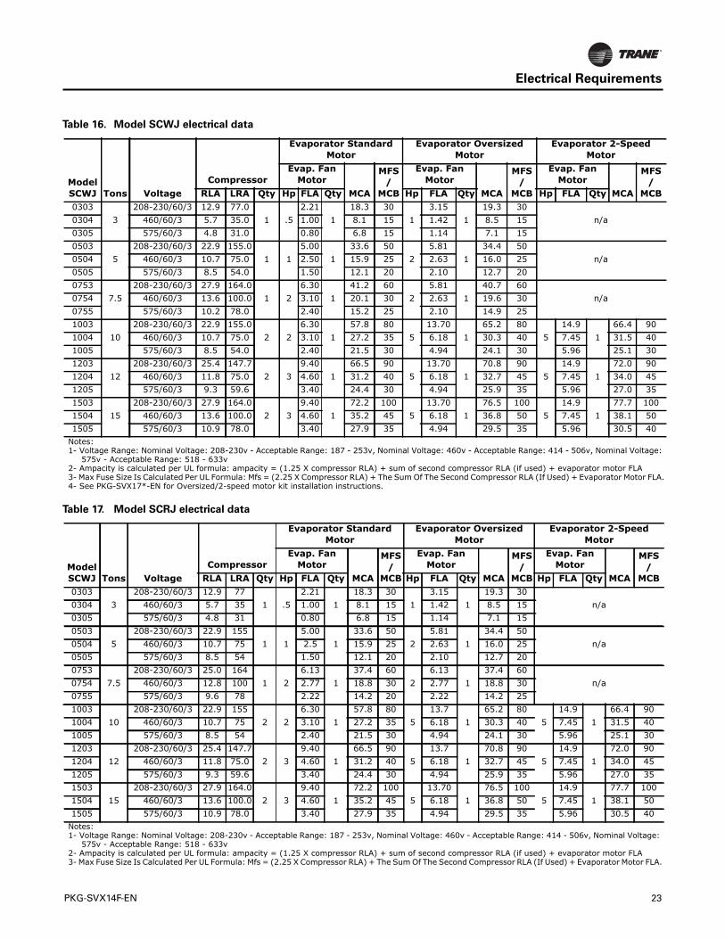
2. See electrical data in Table 16, p. 23. Protect electricalservice from over current and short circuit conditionsin accordance with NEC requirements. Size protectiondevices according to electrical data on unit nameplate.
3. If using a field-supplied disconnect, install it at or nearthe unit in accordance with NEC. Do not mount a field-supplied disconnect on the unit. Reference theelectrical service entrance location on unit submittals.
4. Complete the unit power wiring connections ontoeither the main terminal block or the field-providednonfushed disconnect switch.
5. Provide proper unit grounding in accordance with localand national codes.
Electrical Data Calculations
RLA = rated load amps
Compressor LRA = locked rotor amps
Fan motor LRA = locked rotor amps, N.E.C.Table 430 - 151
FLA = Full load amps, N.E.C.Table 430 - 150
Voltage utilization range is ±10%
Minimum circuit ampacity (MCA) = 1.25 x largest motoramps (FLA or RLA) + the sum of remaining motor amps.
Maximum fuse size (MFS) and maximum circuit breakersize (MCB) = 2.25 x largest motor amps (FLA or RLA) + thesum of the remaining motor amps.
Note: If the rating value determined does not equal astandard current rating of mover current protectivedevice, use the next lower standard rating for themarked maximum rating.
Voltage Range
Voltages must be within +- 10% the nameplate voltage.Ensure the unit voltage is balanced by measuring at thecompressor terminals. Voltage imbalance on three phasesystems can cause motor overheating and prematurefailure. Maximum allowable imbalance is 2.0%.
Voltage Imbalance
Read the voltage at the compressor terminals to determineif it is balanced.Voltage imbalance on three phase systemscan cause motor overheating and premature failure.Themaximum allowable imbalance is 2.0%. Voltageimbalance is defined as 100 times the sum of the deviationof the three voltages from the average (without regard tosign) divided by the average voltage. For example, if thethree measured voltages are 221, 230, and 227, the averagevoltage would be:
The percentage of voltage imbalance is then:
In this example, 2.2% imbalance is notacceptable.Whenever a voltage imbalance of more than2.0% exists, check the voltage at the unit disconnectswitch. If the imbalance at the unit disconnect switch doesnot exceed 2.0%, faulty unit wiring is causing theimbalance. Conduct a thorough inspection of the unitelectrical wiring connections to locate the fault, and makeany repairs necessary.
Figure 17. Air-cooled unit refrigerant piping
WARNING
Proper Field Wiring and GroundingRequired!
All field wiring MUST be performed by qualifiedpersonnel. Improperly installed and grounded fieldwiring poses FIRE and ELECTROCUTION hazards.Toavoid these hazards, you MUST follow requirements forfield wiring installation and grounding as described inNEC and your local/state electrical codes. Failure tofollow code could result in death or serious injury.
Cut
Compressor Expansion Valve
Liquid Line
Condenser Connections
Discharge Line
(221 + 230 + 227)= 226 volts
3
100 * (226-221)
= 2.2%226
22 PKG-SVX14F-EN
Electrical Requirements
Table 16. Model SCWJ electrical data
Model SCWJ Tons Voltage
Compressor
Evaporator Standard Motor
Evaporator Oversized Motor
Evaporator 2-Speed Motor
Evap. Fan Motor
MCA
MFS /
MCB
Evap. Fan Motor
MCA
MFS /
MCB
Evap. Fan Motor
MCA
MFS /
MCBRLA LRA Qty Hp FLA Qty Hp FLA Qty Hp FLA Qty0303
3208-230/60/3 12.9 77.0
1 .52.21
118.3 30
13.15
119.3 30
n/a0304 460/60/3 5.7 35.0 1.00 8.1 15 1.42 8.5 150305 575/60/3 4.8 31.0 0.80 6.8 15 1.14 7.1 150503
5208-230/60/3 22.9 155.0
1 15.00
133.6 50
25.81
134.4 50
n/a0504 460/60/3 10.7 75.0 2.50 15.9 25 2.63 16.0 250505 575/60/3 8.5 54.0 1.50 12.1 20 2.10 12.7 200753
7.5208-230/60/3 27.9 164.0
1 26.30
141.2 60
25.81
140.7 60
n/a0754 460/60/3 13.6 100.0 3.10 20.1 30 2.63 19.6 300755 575/60/3 10.2 78.0 2.40 15.2 25 2.10 14.9 251003
10208-230/60/3 22.9 155.0
2 26.30
157.8 80
513.70
165.2 80
514.9
166.4 90
1004 460/60/3 10.7 75.0 3.10 27.2 35 6.18 30.3 40 7.45 31.5 401005 575/60/3 8.5 54.0 2.40 21.5 30 4.94 24.1 30 5.96 25.1 301203
12208-230/60/3 25.4 147.7
2 39.40
166.5 90
513.70
170.8 90
514.9
172.0 90
1204 460/60/3 11.8 75.0 4.60 31.2 40 6.18 32.7 45 7.45 34.0 451205 575/60/3 9.3 59.6 3.40 24.4 30 4.94 25.9 35 5.96 27.0 351503
15208-230/60/3 27.9 164.0
2 39.40
172.2 100
513.70
176.5 100
514.9
177.7 100
1504 460/60/3 13.6 100.0 4.60 35.2 45 6.18 36.8 50 7.45 38.1 501505 575/60/3 10.9 78.0 3.40 27.9 35 4.94 29.5 35 5.96 30.5 40
Notes:1- Voltage Range: Nominal Voltage: 208-230v - Acceptable Range: 187 - 253v, Nominal Voltage: 460v - Acceptable Range: 414 - 506v, Nominal Voltage:
575v - Acceptable Range: 518 - 633v2- Ampacity is calculated per UL formula: ampacity = (1.25 X compressor RLA) + sum of second compressor RLA (if used) + evaporator motor FLA3- Max Fuse Size Is Calculated Per UL Formula: Mfs = (2.25 X Compressor RLA) + The Sum Of The Second Compressor RLA (If Used) + Evaporator Motor FLA.4- See PKG-SVX17*-EN for Oversized/2-speed motor kit installation instructions.
Table 17. Model SCRJ electrical data
Model SCWJ Tons Voltage
Compressor
Evaporator Standard Motor
Evaporator Oversized Motor
Evaporator 2-Speed Motor
Evap. Fan Motor
MCA
MFS /
MCB
Evap. Fan Motor
MCA
MFS /
MCB
Evap. Fan Motor
MCA
MFS /
MCBRLA LRA Qty Hp FLA Qty Hp FLA Qty Hp FLA Qty0303
3208-230/60/3 12.9 77
1 .52.21
118.3 30
13.15
119.3 30
n/a0304 460/60/3 5.7 35 1.00 8.1 15 1.42 8.5 150305 575/60/3 4.8 31 0.80 6.8 15 1.14 7.1 150503
5208-230/60/3 22.9 155
1 15.00
133.6 50
25.81
134.4 50
n/a0504 460/60/3 10.7 75 2.5 15.9 25 2.63 16.0 250505 575/60/3 8.5 54 1.50 12.1 20 2.10 12.7 200753
7.5208-230/60/3 25.0 164
1 26.13
137.4 60
26.13
137.4 60
n/a0754 460/60/3 12.8 100 2.77 18.8 30 2.77 18.8 300755 575/60/3 9.6 78 2.22 14.2 20 2.22 14.2 251003
10208-230/60/3 22.9 155
2 26.30
157.8 80
513.7
165.2 80
514.9
166.4 90
1004 460/60/3 10.7 75 3.10 27.2 35 6.18 30.3 40 7.45 31.5 401005 575/60/3 8.5 54 2.40 21.5 30 4.94 24.1 30 5.96 25.1 301203
12208-230/60/3 25.4 147.7
2 39.40
166.5 90
513.7
170.8 90
514.9
172.0 90
1204 460/60/3 11.8 75.0 4.60 31.2 40 6.18 32.7 45 7.45 34.0 451205 575/60/3 9.3 59.6 3.40 24.4 30 4.94 25.9 35 5.96 27.0 351503
15208-230/60/3 27.9 164.0
2 39.40
172.2 100
513.70
176.5 100
514.9
177.7 100
1504 460/60/3 13.6 100.0 4.60 35.2 45 6.18 36.8 50 7.45 38.1 501505 575/60/3 10.9 78.0 3.40 27.9 35 4.94 29.5 35 5.96 30.5 40
Notes:1- Voltage Range: Nominal Voltage: 208-230v - Acceptable Range: 187 - 253v, Nominal Voltage: 460v - Acceptable Range: 414 - 506v, Nominal Voltage:
575v - Acceptable Range: 518 - 633v2- Ampacity is calculated per UL formula: ampacity = (1.25 X compressor RLA) + sum of second compressor RLA (if used) + evaporator motor FLA3- Max Fuse Size Is Calculated Per UL Formula: Mfs = (2.25 X Compressor RLA) + The Sum Of The Second Compressor RLA (If Used) + Evaporator Motor FLA.
PKG-SVX14F-EN 23
24 PKG-SVX14F-EN
Installation
Installation Checklist
Reference checklist below to verify all steps required toinstall a deluxe self-contained unit are complete.
This checklist is intended to acquaint installing personnelwith the installation process. It does not replace detailedinstructions in the applicable sections of this manual.
General Unit Requirements
• Install and secure the ductwork to the unit.
• Check unit for shipping damage and material shortage.Refer to the Receiving Checklist.
Electrical Requirements
• Verify that the electrical power supply characteristicscomply with the unit nameplate specifications.
• Inspect all control components; tighten any looseconnections.
• Connect properly sized and protected power supplywiring to a field supplied/installed disconnect and unitpower terminal block, or to the optional unit mounteddisconnect switch.
• Properly ground the unit.
Field Installed Control Wiring (Optional)
Complete the field wiring connections.
Note: All field installed wiring must comply with NEC andapplicable local codes.
Fan Discharge Conversion
Complete the steps below to convert the fan dischargefrom vertical to horizontal.
1. Remove all mid and top fan section panels.
2. Loosen the brackets inside the unit that clamp the midand fan sections together.
3. Remove the control box cover and disconnect themotor power wires. Feed wires up through the unit andsecure out of the way until rotation is complete.
4. Rotate the fan section to desired position.
5. Re-route motor power wires to control box. Ensure allwiring is free and not routed over any sharp edges.
6. Reconnect motor power wires per unit wiring diagram.
7. Bolt and/or clamp all brackets back into place.
8. Replace control box cover and all exterior panels.
9. Verify the fan rotation and motor amp draw.
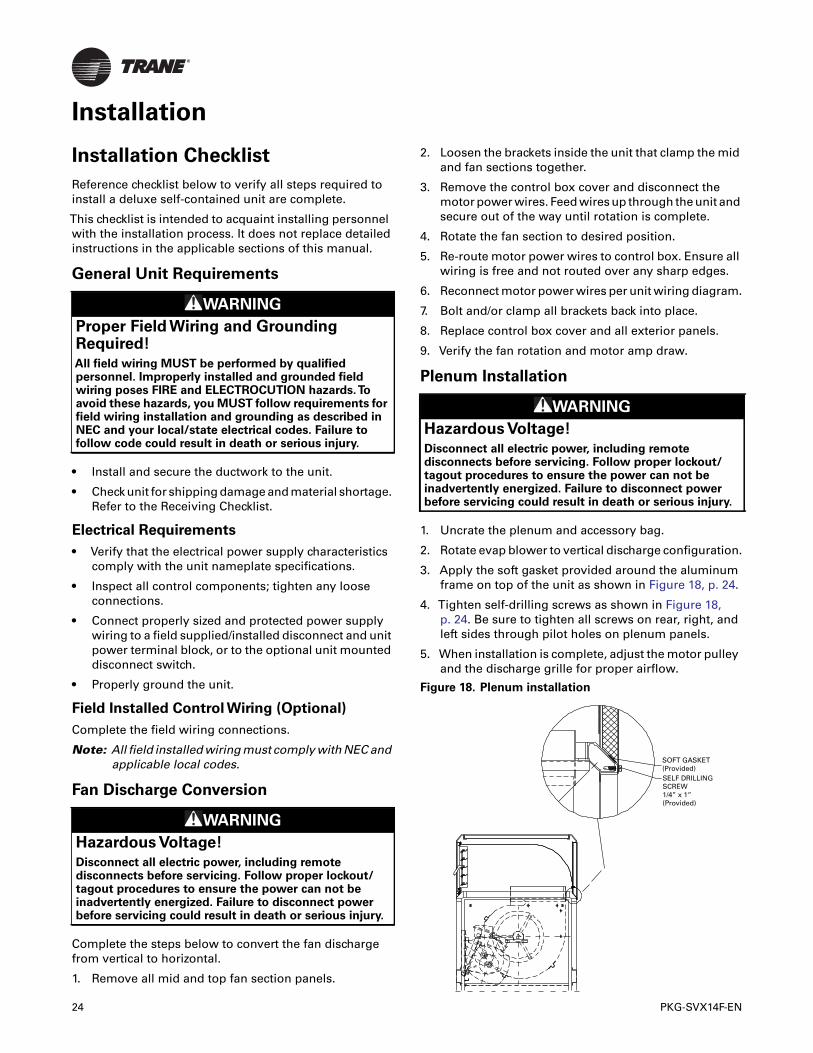
Plenum Installation
1. Uncrate the plenum and accessory bag.
2. Rotate evap blower to vertical discharge configuration.
3. Apply the soft gasket provided around the aluminumframe on top of the unit as shown in Figure 18, p. 24.
4. Tighten self-drilling screws as shown in Figure 18,p. 24. Be sure to tighten all screws on rear, right, andleft sides through pilot holes on plenum panels.
5. When installation is complete, adjust the motor pulleyand the discharge grille for proper airflow.
WARNING
Proper Field Wiring and GroundingRequired!
All field wiring MUST be performed by qualifiedpersonnel. Improperly installed and grounded fieldwiring poses FIRE and ELECTROCUTION hazards.Toavoid these hazards, you MUST follow requirements forfield wiring installation and grounding as described inNEC and your local/state electrical codes. Failure tofollow code could result in death or serious injury.
WARNING
Hazardous Voltage!
Disconnect all electric power, including remotedisconnects before servicing. Follow proper lockout/tagout procedures to ensure the power can not beinadvertently energized. Failure to disconnect powerbefore servicing could result in death or serious injury.
WARNING
Hazardous Voltage!
Disconnect all electric power, including remotedisconnects before servicing. Follow proper lockout/tagout procedures to ensure the power can not beinadvertently energized. Failure to disconnect powerbefore servicing could result in death or serious injury.
Figure 18. Plenum installation
SOFT GASKET(Provided)SELF DRILLINGSCREW1/4” x 1”(Provided)
PKG-SVX14F-EN 25
Pre-StartPre-Startup Checklist
Complete this checklist after installing the unit to verify allrecommended installation procedures are completebefore unit startup.This does not replace the detailedinstructions in the appropriate sections of this manual.Always read the entire section carefully to become familiarwith the procedures.
Receiving
• Inspect unit and components for shipping damage.File damage claims immediately with the deliveringcarrier.
• Check nameplate unit data so that it matches the salesorder requirements.
• Check unit for missing material. Look for ship-withaccessories that are packaged separately and placedinside the access panel, fan section, or compressorsection. See the “Receiving and Handling” section.
Unit Location
• Ensure the unit location is adequate for unitdimensions, ductwork, piping, and electricalconnections.
• Ensure access and maintenance clearances around theunit are adequate. See the “Service Access” section.
Unit Mounting
Remove shipping brackets on the compressor assemblyand supply fan.
Component Overview
• Verify the fan and motor sheaves are aligned.
• Check the belt tension for proper adjustment.
• Ensure the fan rotates freely.
• Tighten locking screws, bearing set screws andsheaves.
• Ensure bearing locking collars do not wobble whenrotated.
• Ensure all air filters are properly installed withconsideration of size and air flow.
• Manually rotate the evaporator fan to ensure freemovement. Verify that all of the fan mountinghardware is tight.
Ductwork
Verify that all ductwork conforms to NFPA 90A or 90B andall applicable local codes.
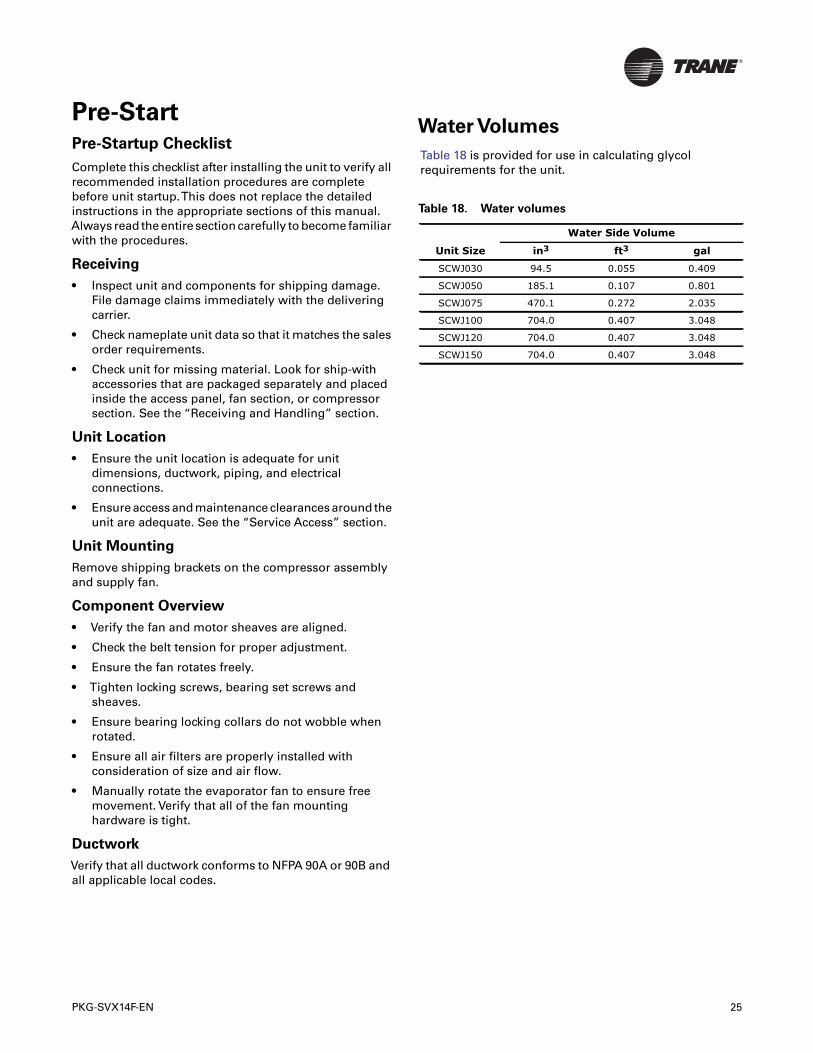
Water Volumes
Table 18 is provided for use in calculating glycolrequirements for the unit.
Table 18. Water volumes
Unit Size
Water Side Volume
in3 ft3 gal
SCWJ030 94.5 0.055 0.409
SCWJ050 185.1 0.107 0.801
SCWJ075 470.1 0.272 2.035
SCWJ100 704.0 0.407 3.048
SCWJ120 704.0 0.407 3.048
SCWJ150 704.0 0.407 3.048
26 PKG-SVX14F-EN
Unit Startup Procedures
1. Check all electrical connections for tightness.
2. Verify unit accessories are properly set and installed.
3. Model SCWJ: Verify condenser water piping isproperly connected, supply, and return.
4. Model SCRJ: Verify refrigerant piping is properlyconnected, hot gas, and liquid.
5. Inspect all ductwork and duct connections.
6. Check for proper belt tension.
7. Check fan drive sheaves, pulleys, and bearings.
Unit Startup Checklist
1. Turn the thermostat to the OFF position.
2. Engage power supply by closing power disconnect.
3. Switch thermostat to fan position and adjusttemperature setting below room temperature.Evaporator fan should start.
4. Check evaporator section for proper operation.
5. Switch thermostat to cool position and adjusttemperature setting to below room temperature.Theevaporator fan and compressor(s) should start.
Note: These units are equipped with high efficiency scrollcompressors. Check for proper scroll rotation priorto operating unit.
6. Check the evaporator fan for proper rotation. If fanrotation is incorrect, switch thermostat to Off positionand disconnect power. Reverse two phase leads atdisconnect and return back to Step 1 of startup.
7. Allow unit to run until all system temperatures andpressures stabilize.
8. Check systems for proper operation and performance.Observe unit in operation and check for unusual noise,vibration, belt, and fan clearances.
Sequence of Operation
The thermostat controls the unit operation. It has bothmanual and automatic switches so the thermostatmaintains desired comfort levels.
The fan switch allows manual selection of the fan speedusing the On or Auto setting.With the switch set in the Onposition, the evaporator fan runs continuously,independent from the thermostat temperature setting.TheAuto position cycles the evaporator fan on and off withthe demand for heating or cooling.
The system switch may have two or more positions. Forexample, using a cooling only thermostat, the systemswitch can be set in the Off or the Cool position.The Offposition disconnects power from the thermostat contactsthat control the condensing unit.This prevents thecondensing unit from running, regardless of thethermostat temperature setting.The evaporator fan maycirculate air if the fan switch is in the On position.With theswitch in the Cool position, the condensing unit andevaporator will operate on a signal from the thermostatcalling for cooling.
With the fan switch set to Auto and the system switch setto Cool, the following sequence takes place. On a rise inroom temperature, the thermostat contacts close toprovide power to the evaporator fan contactor, thecondensing unit fan contactor, and the condensing unitcompressor contactors. As the room temperature reachessetpoint, the thermostat contacts open to de-energize allcontactors, and the system cycles off.This system willremain off until additional cooling is required and the cyclerepeats.
WARNING
Hazardous Service Procedures!
The maintenance and troubleshooting proceduresrecommended in this manual could result in exposureto electrical, mechanical or other potential safetyhazards. Always refer to the safety warnings providedthroughout this manual concerning these procedures.Unless specified otherwise, disconnect all electricalpower including remote disconnect and discharge allenergy storing devices such as capacitors beforeservicing. Follow proper lockout/tagout procedures toensure the power can not be inadvertently energized.When necessary to work with live electricalcomponents, have a qualified licensed electrician orother individual who has been trained in handling liveelectrical components perform these tasks. Failure tofollow all of the recommended safety warningsprovided, could result in death or serious injury.
Maintenance
This section describes specific maintenance proceduresthat must be preformed as a part of the normalmaintenance program. Always disconnect electricalpower to the unit before performing these procedures andheed all warnings and cautions.
Periodic Maintenance Checklist
Inspect coil surface for cleanliness. Clean as required,referring to the “Coil Cleaning” section.
Annual Maintenance Checklist
• Perform all monthly maintenance inspections.• Perform seasonal startup checks.• Leak test refrigerant circuits. Inspect contacts of fan
motor contactors and relays. Replace all worncontacts.
• Clean and repaint any corroded surface.
Water Quality
The water quality should be checked periodically. SeeTable 19, p. 27.
Cleaning the Condenser Coils
Note: The following coil cleaning procedures apply onlyto outdoor air cooled condenser coils. Do not usethese procedures for the reheat or evaporator coils.
Clean the coil at least once each year or more frequently iflocated in a dirty environment, to help maintain properunit operating efficiency. High discharge pressures are agood indication that the coil needs cleaning. Follow thedetergent manufacturer instructions as closely as possibleto avoid potential coil damage.
To clean the refrigerant coil, use a soft brush and sprayer,such as a garden pump up or high pressure type. Inaddition, use a quality detergent; like “SPREX AC’, “OAKITE 161” or “OAKITE 166” and “COILOX.”
Note: If detergent is strongly alkaline (i.e. has a pH valuegreater that 8.5) after mixing, you must add analuminum corrosion inhibitor.
Coil Cleaning Procedure
WARNING
Hazardous Voltage!
Disconnect all electric power, including remotedisconnects before servicing. Follow proper lockout/tagout procedures to ensure the power can not beinadvertently energized. Failure to disconnect powerbefore servicing could result in death or serious injury.
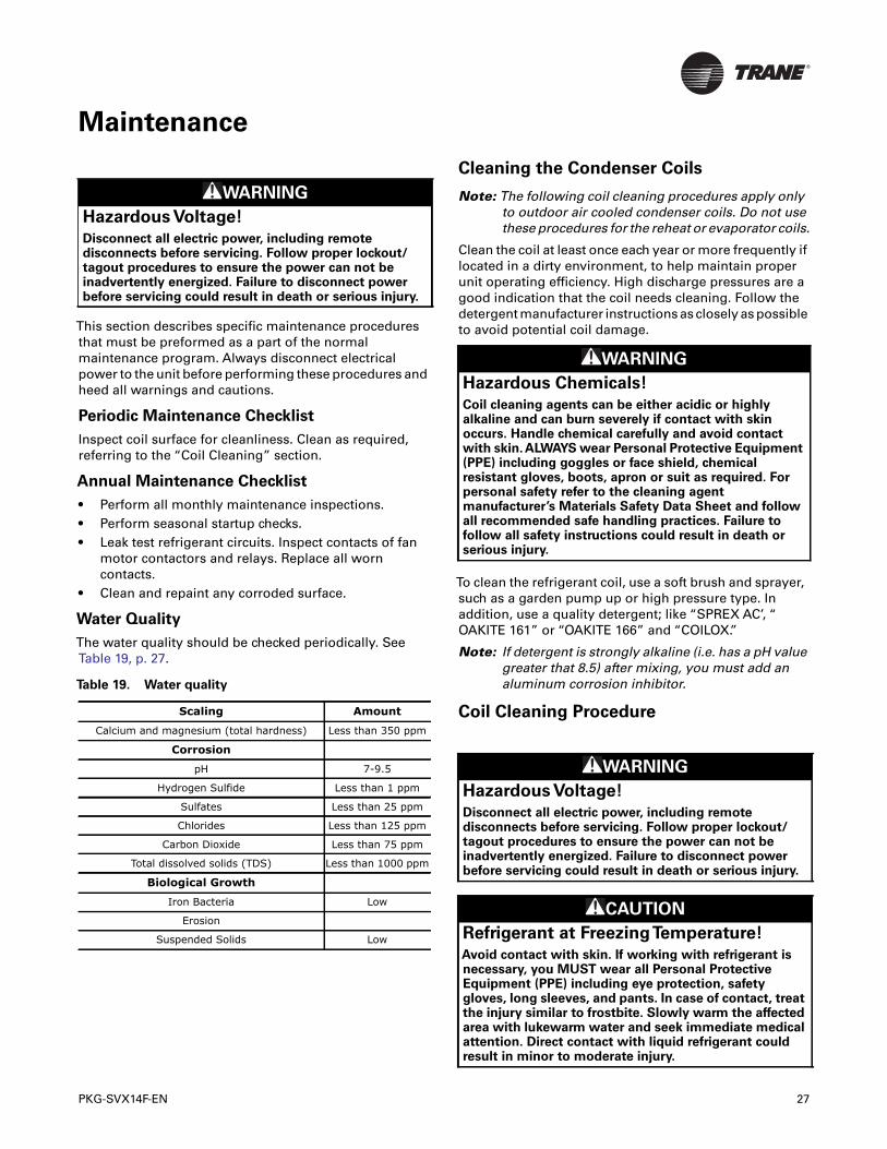
Table 19. Water quality
Scaling Amount
Calcium and magnesium (total hardness) Less than 350 ppm
Corrosion
pH 7-9.5
Hydrogen Sulfide Less than 1 ppm
Sulfates Less than 25 ppm
Chlorides Less than 125 ppm
Carbon Dioxide Less than 75 ppm
Total dissolved solids (TDS) Less than 1000 ppm
Biological Growth
Iron Bacteria Low
Erosion
Suspended Solids Low
WARNING
Hazardous Chemicals!
Coil cleaning agents can be either acidic or highlyalkaline and can burn severely if contact with skinoccurs. Handle chemical carefully and avoid contactwith skin. ALWAYS wear Personal Protective Equipment(PPE) including goggles or face shield, chemicalresistant gloves, boots, apron or suit as required. Forpersonal safety refer to the cleaning agentmanufacturer’s Materials Safety Data Sheet and followall recommended safe handling practices. Failure tofollow all safety instructions could result in death orserious injury.
WARNING
Hazardous Voltage!
Disconnect all electric power, including remotedisconnects before servicing. Follow proper lockout/tagout procedures to ensure the power can not beinadvertently energized. Failure to disconnect powerbefore servicing could result in death or serious injury.
CAUTION
Refrigerant at FreezingTemperature!
Avoid contact with skin. If working with refrigerant isnecessary, you MUST wear all Personal ProtectiveEquipment (PPE) including eye protection, safetygloves, long sleeves, and pants. In case of contact, treatthe injury similar to frostbite. Slowly warm the affectedarea with lukewarm water and seek immediate medicalattention. Direct contact with liquid refrigerant couldresult in minor to moderate injury.
PKG-SVX14F-EN 27
Maintenance
1. Disconnect power to the unit.
2. Remove panels from the unit to gain access to the coil.
3. Use a soft brush to remove loose dirt and debris formboth sides of the coil.
4. Straighten coil fins with fin comb as required.
5. Mix the detergent with water according to themanufacturers instructions.
Observe all recommendations of the cleansermanufacturer.The coil cleanser manufacturer’srecommendations, warnings and cautions will at all timestake precedence to these instructions.
1. Place solution in the sprayer. Be sure to follow theseguidelines if using a high pressure sprayer:
a. Keep minimum nozzle spray angle 15°.
b. Spray solution at a 90° angle to the coil face.
c. Keep sprayer nozzle at least six inches from the coil.
d. Sprayer pressure must not exceed 600 psi.
2. Spray leaving air side of the coil first then spray theentering air side of the coil. Allow the detergent andwater solution to stand on the coil for five minutes.
3. Rinse both sides of the coil with cool, clean water.
4. Inspect the coil. If it still appears dirty, repeat thecleaning procedure.
5. Reinstall all unit components and panels, and restoreelectrical power and gas supply to the unit.
Refrigerant System
Special Note on Refrigerant Emissions
Follow theTrane recommended procedures on operation,maintenance, and service to ensure refrigerantconservation and emission reduction.
Also, pay specific attention to the following:
• Whenever removing refrigerant from equipment,recover for reuse, recycle, reprocess (reclaim), orproperly destroy it.
• Always determine possible refrigerant recycling orreclaiming requirements before beginning recovery.Questions about recovered refrigerants and
acceptable refrigerant quality standards are addressedin AHRI Standard 700.
• Use approved containment vessels and safetystandards. Comply with all applicable transportationstandards when shipping refrigerant containers.
• To minimize emissions while recovering refrigerant,use recycling equipment. Always attempt to usemethods that pull the lowest possible system vacuumwhile recovering and condensing refrigerant intocontainment.
• When leak checking with trace refrigerant andnitrogen, use R410a. Be aware of any new leak testmethods that eliminate refrigerant as a trace gas.
• When cleaning system components or parts, do notuse CFC11 (R11) or CFC113 (R113). Refrigeration systemclean up methods using filters and dryers arerecommended. Do not use solvents that have ozonedepletion factors. Properly dispose of used materials.
• Take extra care to properly maintain all serviceequipmentdirectlysupportingrefrigerantserviceworksuch as gauges, hoses, vacuum pumps, and recyclingequipment.
• Stay aware of unit enhancements, conversionrefrigerants, compatible parts, manufacturer’srecommendations that reduce refrigerant emissionsand increase equipment operating efficiencies. Followspecific manufacturer’s guidelines for conversion ofexisting systems.
• To reduce power generation emissions, maximizeequipment performance with improved maintenanceand operations will help conserve energy resources.
In the event of required system repair, leak test the liquidline, evaporator coil, and suction line at pressures dictatedby local codes, and using the following guidelines.
WARNING
Confined Space Hazards!
Do not work in confined spaces where refrigerant orother hazardous, toxic or flammable gas may beleaking. Refrigerant or other gases could displaceavailable oxygen to breathe, causing possibleasphyxiation or other serious health risks. Some gasesmay be flammable and or explosive. If a leak in suchspaces is detected, evacuate the area immediately andcontact the proper rescue or response authority. Failureto take appropriate precautions or to react properly tosuch potential hazards could result in death or seriousinjury.
WARNING
Hazard of Explosion!
Use only dry nitrogen with a pressure regulator forpressurizing unit. Do not use acetylene, oxygen orcompressed air or mixtures containing them forpressure testing. Do not use mixtures of a hydrogencontaining refrigerant and air above atmosphericpressure for pressure testing as they may becomeflammable and could result in an explosion.Refrigerant, when used as a trace gas should only bemixed with dry nitrogen for pressurizing units. Failureto follow these recommendations could result in deathor serious injury or equipment or property-onlydamage.
WARNING
Hazard of Explosion!
Do not exceed 200 psig when leak testing system.Failure to follow these instructions could result in anexplosion which could result in death or serious injury.
28 PKG-SVX14F-EN
Maintenance
1. Charge enough refrigerant and dry nitrogen into thesystem to raise the pressure to 100 psig.
2. Use a halogen leak detector or soap bubbles to checkfor leaks. Check interconnecting piping joints, theevaporator coil connections, and all accessoryconnections.
3. If a leak is detected on the SCWH or SCRJ unit, releasethe test pressure, break the connections andreassemble as a new joint, using proper brazingtechniques.
4. If a leak is detected on a CTA micro-channel condenser,replace condenser coil.
5. If no leak is detected, use nitrogen to increase the testpressure to 150 psig and repeat the leak test. Also, usesoap bubbles to check for leaks when nitrogen isadded.
6. Retest the system to make sure new connections aresolid.
7. If a leak is suspected after the system has been fullycharged with refrigerant, use a halogen leak detectoror soap bubbles to check for leaks.
Refrigerant Evacuation
For field evacuation, use a rotary style vacuum pumpcapable of pulling a vacuum of 1000 microns or less.Whenconnecting the vacuum pump to a refrigeration system, itis important to manifold the pump to both the high and lowside of the system. Follow the pump manufacturer’sdirections.
Charging the Refrigerant System
To completely charge the system, charge gaseousrefrigerant into the suction line schrader valve with theunit running. However, make sure that some refrigerant ispresent in each circuit before starting the compressors.
See General Data Table 1, p. 7 and Table 2, p. 8 for normaloperating conditions, and controls adjustment values.
Periodic Checklists
WARNING
Hazardous Pressures!
Always use pressure regulators, valves, and gauges tocontrol drum and line pressures when pressure testingequipment. Failure to follow these instructions couldresult in an explosion causing death, serious injury, orequipment damage.
WARNING
Hazardous Pressures!
If a heat source is required to raise the tank pressureduring removal of refrigerant from cylinders, use onlywarm water or heat blankets to raise the tanktemperature. Do not exceed a temperature of 150°F. Donot, under any circumstances apply direct flame to anyportion of the cylinder. Failure to follow these safetyprecautions could result in a sudden rise of pressurepossibly resulting in a violent explosion which couldresult in death or serious injury.
NOTICE:
Motor Winding Damage!
Do not use a megohm meter or apply voltage greaterthan 50 DVC to a compressor motor winding while it isunder a deep vacuum. Voltage sparkover may causedamage to the motor windings.
NOTICE:
Compressor Damage!
Do not allow liquid refrigerant to enter the suction line.Excessive liquid accumulation in the liquid lines mayresult in compressor damage.
NOTICE:
Compressor Damage!
Never manually or automatically pump down systembelow 7 psig.This will cause the compressor to operatein a vacuum and result in compressor damage.
WARNING
Hazardous Service Procedures!
The maintenance and troubleshooting proceduresrecommended in this manual could result in exposureto electrical, mechanical or other potential safetyhazards. Always refer to the safety warnings providedthroughout this manual concerning these procedures.Unless specified otherwise, disconnect all electricalpower including remote disconnect and discharge allenergy storing devices such as capacitors beforeservicing. Follow proper lockout/tagout procedures toensure the power can not be inadvertently energized.When necessary to work with live electricalcomponents, have a qualified licensed electrician orother individual who has been trained in handling liveelectrical components perform these tasks. Failure tofollow all of the recommended safety warningsprovided, could result in death or serious injury.
PKG-SVX14F-EN 29
Maintenance
Monthly Checklist
The following checklist provides the recommendedmaintenance schedule to keep the unit running efficiently.
1. Inspect unit air filters. Clean or replace if airflow isblocked or if filters are dirty.
2. Inspect coils for icing. Icing on the coils may indicatelow airflow supply, restricted airflow from dirty fins.
3. Check the fan belt condition and tension. Adjusttension if belt is floppy or squeals continually.
4. Check and record operating pressures.
Semi-Annual Maintenance
1. Verify the fan motor is properly aligned and boltedtight to the motor frame.
2. With power disconnected, manually rotate the fanwheel to check for obstructions in the housing orinterference with fan blades. Remove obstructions anddebris. Center the fan wheel if necessary.
3. Check the fan assembly sheave alignment.Tighten setscrews to their proper torques.
Note: Perform this procedure monthly if the unit is in acoastal or corrosive environment.
Annual Maintenance
Check and tighten all set screws, bolts, locking collars andsheaves.
1. Inspect, clean, and tighten all electrical connections.
2. Visually inspect entire unit casing for chips orcorrosion. Remove rust or corrosion and repaintsurfaces.
3. Visually check for leaks in refrigerant piping.
4. Inspect fan, motor, and control contacts. Replace badlyworn or eroded contacts.
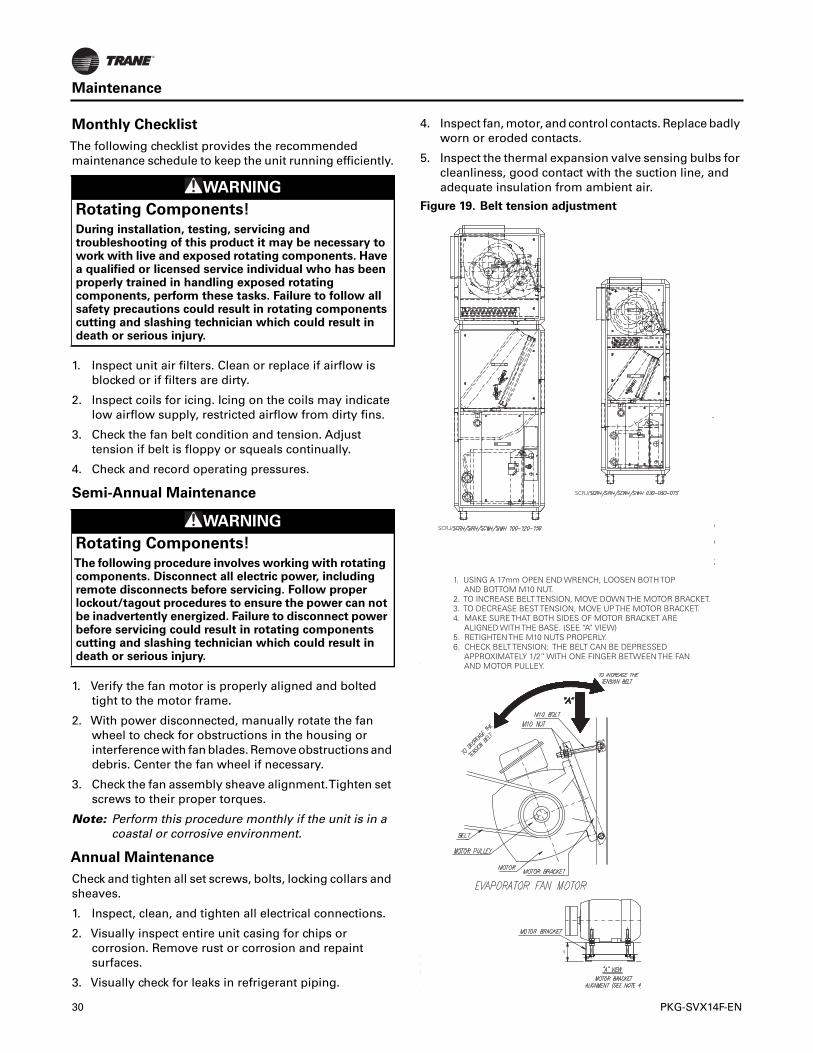
5. Inspect the thermal expansion valve sensing bulbs forcleanliness, good contact with the suction line, andadequate insulation from ambient air.WARNING
Rotating Components!
During installation, testing, servicing andtroubleshooting of this product it may be necessary towork with live and exposed rotating components. Havea qualified or licensed service individual who has beenproperly trained in handling exposed rotatingcomponents, perform these tasks. Failure to follow allsafety precautions could result in rotating componentscutting and slashing technician which could result indeath or serious injury.
WARNING
Rotating Components!
The following procedure involves working with rotatingcomponents. Disconnect all electric power, includingremote disconnects before servicing. Follow properlockout/tagout procedures to ensure the power can notbe inadvertently energized. Failure to disconnect powerbefore servicing could result in rotating componentscutting and slashing technician which could result indeath or serious injury.
Figure 19. Belt tension adjustment
1. USING A 17mm OPEN END WRENCH, LOOSEN BOTH TOP AND BOTTOM M10 NUT.2. TO INCREASE BELT TENSION, MOVE DOWN THE MOTOR BRACKET.3. TO DECREASE BEST TENSION, MOVE UP THE MOTOR BRACKET.4. MAKE SURE THAT BOTH SIDES OF MOTOR BRACKET ARE ALIGNED WITH THE BASE. (SEE “A” VIEW)5. RETIGHTEN THE M10 NUTS PROPERLY.6. CHECK BELT TENSION: THE BELT CAN BE DEPRESSED APPROXIMATELY 1/2” WITH ONE FINGER BETWEEN THE FAN AND MOTOR PULLEY.
SCRJ/
SCRJ/
30 PKG-SVX14F-EN
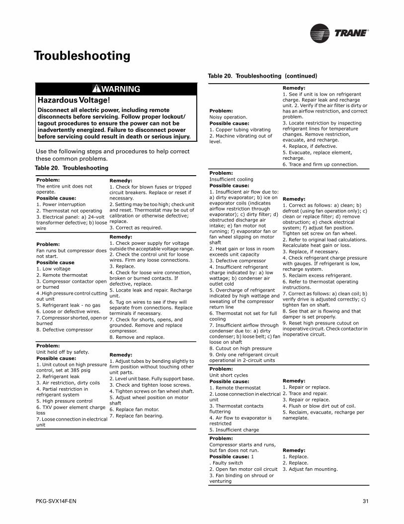
PKG-SVX14F-EN 31
Troubleshooting
Use the following steps and procedures to help correctthese common problems.
WARNING
Hazardous Voltage!
Disconnect all electric power, including remotedisconnects before servicing. Follow proper lockout/tagout procedures to ensure the power can not beinadvertently energized. Failure to disconnect powerbefore servicing could result in death or serious injury.
Table 20. Troubleshooting
Problem:The entire unit does not operate. Possible cause:1. Power interruption 2. Thermostat not operating 3. Electrical panel: a) 24-volt transformer defective; b) loose wire
Remedy:1. Check for blown fuses or tripped circuit breakers. Replace or reset if necessary. 2. Setting may be too high; check unit and reset. Thermostat may be out of calibration or otherwise defective; replace. 3. Correct as required.
Problem: Fan runs but compressor does not start. Possible cause 1. Low voltage 2. Remote thermostat 3. Compressor contactor open or burned4 .High pressure control cutting out unit 5. Refrigerant leak - no gas 6. Loose or defective wires. 7. Compressor shorted, open or burned 8. Defective compressor
Remedy: 1. Check power supply for voltage outside the acceptable voltage range. 2. Check the control unit for loose wires. Firm any loose connections. 3. Replace. 4. Check for loose wire connection, broken or burned contacts. If defective, replace. 5. Locate leak and repair. Recharge unit. 6. Tug on wires to see if they will separate from connections. Replace terminals if necessary. 7. Check for shorts, opens, and grounded. Remove and replace compressor. 8. Remove and replace.
Problem: Unit held off by safety. Possible cause: 1. Unit cutout on high pressure control, set at 385 psig 2. Refrigerant leak 3. Air restriction, dirty coils 4. Partial restriction in refrigerant system 5. High pressure control 6. TXV power element charge loss 7. Loose connection in electrical unit
Remedy: 1. Adjust tubes by bending slightly to firm position without touching other unit parts. 2. Level unit base. Fully support base. 3. Check and tighten loose screws. 4. Tighten screws on fan wheel shaft. 5. Adjust wheel position on motor shaft 6. Replace fan motor. 7. Replace fan bearing.
Problem: Noisy operation. Possible cause: 1. Copper tubing vibrating 2. Machine vibrating out of level.
Remedy: 1. See if unit is low on refrigerant charge. Repair leak and recharge unit. 2. Verify if the air filter is dirty or has an airflow restriction, and correct problem. 3. Locate restriction by inspecting refrigerant lines for temperature changes. Remove restriction, evacuate, and recharge. 4. Replace, if defective. 5. Evacuate, replace element, recharge. 6. Trace and firm up connection.
Problem: Insufficient cooling Possible cause: 1. Insufficient air flow due to: a) dirty evaporator; b) ice on evaporator coils (indicates airflow restriction through evaporator); c) dirty filter; d) obstructed discharge air intake; e) fan motor not running; f) evaporator fan or fan wheel slipping on motor shaft 2. Heat gain or loss in room exceeds unit capacity 3. Defective compressor 4. Insufficient refrigerant charge indicated by: a) low wattage; b) condenser air outlet cold 5. Overcharge of refrigerant indicated by high wattage and sweating of the compressor return line 6. Thermostat not set for full cooling 7. Insufficient airflow through condenser due to: a) dirty condenser; b) loose belt; c) fan loose on shaft 8. Cutout on high pressure 9. Only one refrigerant circuit operational in 2-circuit units
Remedy: 1. Correct as follows: a) clean; b) defrost (using fan operation only); c) clean or replace filter; d) remove obstruction; e) check electrical system; f) adjust fan position. Tighten set screw on fan wheel. 2. Refer to original load calculations. Recalculate heat gain or loss. 3. Replace, if necessary. 4. Check refrigerant charge pressure with gauges. If refrigerant is low, recharge system. 5. Reclaim excess refrigerant. 6. Refer to thermostat operating instructions. 7. Correct as follows: a) clean coil; b) verify drive is adjusted correctly; c) tighten fan on shaft. 8. See that air is flowing and that damper is set properly. 9. Reset high pressure cutout on inoperative circuit. Check contactor in inoperative circuit.
Problem: Unit short cycles Possible cause:1. Remote thermostat 2. Loose connection in electrical unit 3. Thermostat contacts fluttering 4. Air flow to evaporator is restricted 5. Insufficient charge
Remedy: 1. Repair or replace. 2. Trace and repair. 3. Repair or replace. 4. Flush or blow dirt out of coil. 5. Reclaim, evacuate, recharge per nameplate.
Problem: Compressor starts and runs, but fan does not run. Possible cause: 1. Faulty switch 2. Open fan motor coil circuit 3. Fan binding on shroud or venturing
Remedy: 1. Replace. 2. Replace. 3. Adjust fan mounting.
Table 20. Troubleshooting (continued)
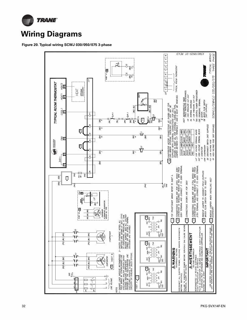
Wiring Diagrams
Figure 20. Typical wiring SCWJ 030/050/075 3-phase
32 PKG-SVX14F-EN
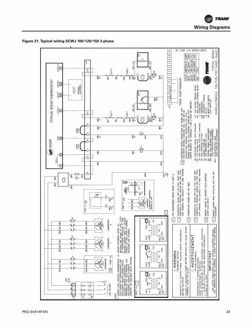
Wiring Diagrams
Figure 21. Typical wiring SCWJ 100/120/150 3-phase
PKG-SVX14F-EN 33
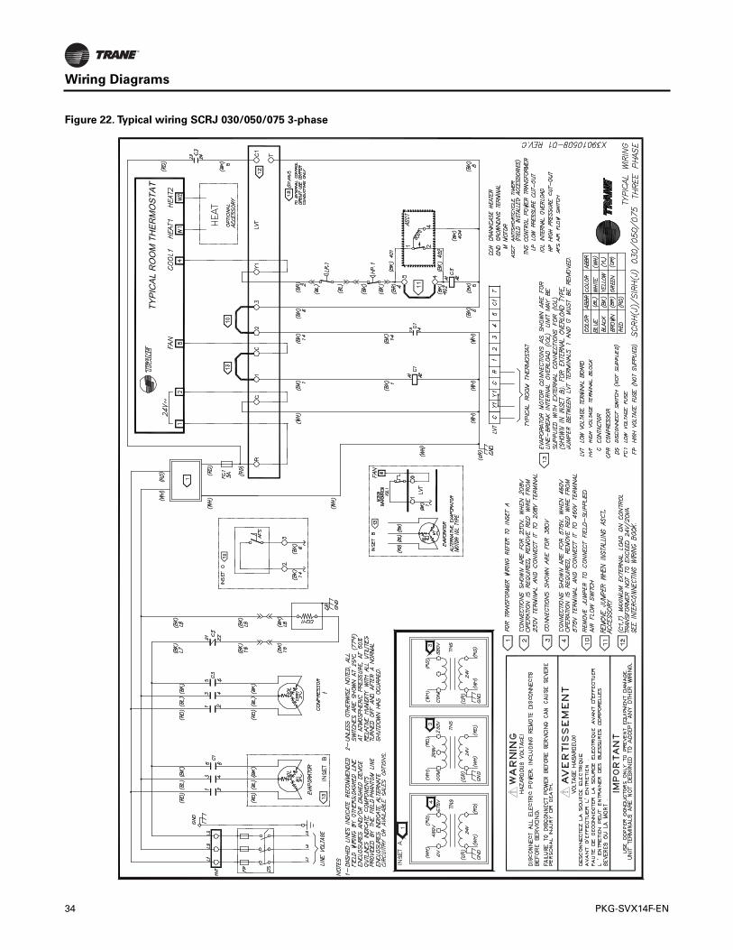
Wiring Diagrams
Figure 22. Typical wiring SCRJ 030/050/075 3-phase
34 PKG-SVX14F-EN
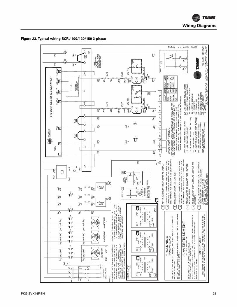
Wiring Diagrams
Figure 23. Typical wiring SCRJ 100/120/150 3-phase
PKG-SVX14F-EN 35
Trane optimizes the performance of homes and buildings around the world. A business of Ingersoll Rand, the leader increating and sustaining safe, comfortable and energy efficient environments,Trane offers a broad portfolio of advancedcontrols and HVAC systems, comprehensive building services, and parts. For more information, visit www.Trane.com.
Trane has a policy of continuous product and product data improvement and reserves the right to change design and specifications without notice.
We are committed to using environmentally
conscious print practices that reduce waste.
© 2014Trane All rights reserved
PKG-SVX14F-EN 30 Jan 2014
Supersedes PKG-SVX14F-EN (01 Oct 2013)