Embed Size (px)
Citation preview

T-41/T-43 and ST-41/ST-43P T F E - L I N E D V A L V E S
The No. 1 Lined Valve in the CPI
Quality System
CertificateBulletin V-171c
Installation, Operation and Maintenance


3
FOREWORDFlowserve Corporation, Flow Control Division hasestablished this Installation, Operating, and MaintenanceManual to facilitate the installation, operation and repair ofT-41 and T-43 valves.
It is recommended that questions or concerns involving theprocesses described in this manual be directed to the localSales Representative of the Flowserve Corporation. OnlyFlowserve replacement repair parts and assembly tooling
Flow Control Division
Section 1.0
made or designed by Flowserve Corporation should beused. Part numbers referenced in the following sections areavailable from Flowserve Corporation, Flow Control Division.
You can also contact Flowserve directly by writing to:
Flowserve CorporationFlow Control DivisionP.O. Box 2609Cookeville, TN 38502-2609
TABLE OF CONTENTSSection Title Page
Foreword
I. Installation Instructions . . . . . . . . . . . . . . . . . . . . . . . . . . . . . . . . . . . . . . . . . . . . . . . . . . . . . . 5
II. Operating/Maintenance. . . . . . . . . . . . . . . . . . . . . . . . . . . . . . . . . . . . . . . . . . . . . . . . . . . . . . . 6
III. Valve Disassembly . . . . . . . . . . . . . . . . . . . . . . . . . . . . . . . . . . . . . . . . . . . . . . . . . . . . . . . . . . 7
IV. Valve Assembly. . . . . . . . . . . . . . . . . . . . . . . . . . . . . . . . . . . . . . . . . . . . . . . . . . . . . . . . . . . . . 7
V. Gear Installation . . . . . . . . . . . . . . . . . . . . . . . . . . . . . . . . . . . . . . . . . . . . . . . . . . . . . . . . . . . . 8
VI. Recommended Spare Parts & Parts List . . . . . . . . . . . . . . . . . . . . . . . . . . . . . . . . . . . . . . . . . 9-10
Material SelectionSelecting the proper fastener material is the ultimateresponsibility of the customer because the supplier does nottypically know in what service the valves will be used or whatelements may be present in the environment. Flowservenormally supplies B7 (carbon steel) for ductile cast iron andcarbon steel valves. For stainless steel and high alloy valves,B8 (stainless steel) fasteners are supplied as standard. Allfasteners used must have a minimum yield strength of40,000 PSI, a minimum elongation of 12% and be com-patible with the process fluid. Determining compatibility tothe process fluid goes beyond a material being resistant togeneral corrosion because the more important considerationis a material’s resistance to stress corrosion cracking.Depending on the service, it may make sense to use B7fasteners on high alloy valves. One such service would bemarine environments because of stainless steel’s suscep-tibility to stress corrosion cracking in chloride environments.Another key aspect of fasteners is frequent visual inspection.Because of the common practice of using steel fastenersrather than stainless steel to avoid chloride stress corrosioncracking, visual inspection is recommended to monitor thegeneral corrosion of these fasteners. If jacketing or insulationis used on a valve, it must be periodically removed for visualinspection of the fasteners. If you wish assistance indetermining the proper fasteners to use, please refer to theattached chart or contact Flowserve’s Materials EngineeringGroup at (937) 476-6100.
Design & TypeFlowserve’s valve design standards adopt ANSI B18.2.1(1981) as the standard for fastener type and design. Thisnational standard requires that finished hex “head” capscrews be used with the head of the fastener is turned. Afinished hex “head” cap screw and a heavy hex cap screwhave a bearing surface under the head to minimize frictionalresistance during tightening. They also comply to qualifiedbody dimensions and fully formed head dimensions. FlowControl Division’s policy is to use finished hex “head” andheavy hex “head” cap screws for all pressure retainingfasteners. This includes top caps, packing adjusters, plugadjusters, bottom caps, body halves or other pressureretaining components. Compliance is made with ANSIB18.2.2 (1987), Square and Hex Nuts, when studs and heavyhex nuts are required. Additional information on these itemsmay be obtained from Flowserve Corporation, Flow ControlDivision, Cookeville, Tennessee.
PRESSURE CONTAINING FASTENERS

4
Flow Control Division
Section 1.0
TABLE 1CAP SCREWS - STUDS
HHCS - Finished Heavy Hex Head Cap ScrewHCS - Finished Hex Head Cap ScrewSTUD - StudDimensions per ANSI B18.2.1
B840 - 304 Stainless Steel per ASTM A193, Grade B8, Class 1, 40 KSI Min. Yield Strength, 12% Min. El.B7 - Chromium - Molybdenum Alloy Steel per ASTM A193, Grade B7B7M - Chromium - Molybdenum Alloy Steel per ASTM A193, Grade B7M, 100% hardness testedB7MT - Chromium - Molybdenum Alloy Steel per ASTM A193, Grade B7M, 100% hardness tested, PTFE coated, Dupont SP11C, Type B - Color blue or
greenB8M - 316 Stainless Steel per ASTM A193, Grade B8M, Class 1, 40 KSI Min. Yield Strength, 12% Min. El.B8C2 - 304 Stainless Steel per ASTM A193, Grade B8, Class 2C20 - Carpenter C20, CB-3 (UNS N08020), ASTM B473, 40 KSI Min. Yield Strength, 12% Min. El.HC - Hastelloy C276 (UNS N10276), ASTM B574I625 - Inconel 625 (UNS N006625), ASTM B446I825 - Incoloy 825 (UNS N08825), ASTM B425, 40 KSI Min. Yield Strength, 12% Min. El.IN - Inconel 600 (UNS N0660), ASTM B166, 40 KSI Min. Yield Strength, 12% Min. El.M - Monel (UNS N04400), ASTM B164, Class A or B, 40 KSI Min. Yield Strength, 12% Min. El.HB - Hastelloy B (UNS 10665), ASTM B335I718 - Incoloy 718, AMS 5596BMKH - Monel K-500, Cold drawn and aged hardened, QQN-286 and ASTM F468L7 - Chromium-Molybdenum Alloy Steel per ASTM A320, Grade L7L7M - Chromium-Molybdenum Alloy Steel per ASTM A320, Grade L7M, 100% hardness testedL7T - Chromium-Molybdenum Alloy Steel per ASTM A320, Grade L7, PTFE coated, DuPont SP11C, Type B - Color blue or greenL7MT - Chromium-Molybdenum Alloy Steel per ASTM A320, Grade L7M, 100% hardness tested, PTFE coated, DuPont SP11C, Type B - Color blue or
greenN - Nickel per ASTM B160 (UNS N0220), 40 KSI Min. Yield Strength, 12% Min. El.B7YC - Chromium-Molybdenum Steel per A193, Grade B7, Yellow Zinc Dichromate Plated
TABLE 2NUTS
HN - Finished Heavy Hex NutXN - Finished Hex NutHXN - Regular Heavy Hex Nut
8 - 304 Stainless Steel per ASTM A194, Grade 88M - 316 Stainless Steel per ASTM A194, Grade 8M2H - ASTM A194, Grade 2H2HM - ASTM A194, Grade 2HM7M - ASTM A194, Grade 7M, 100% hardness tested7MT - ASTM A194, Grade 7M, 100% hardness tested, PTFE coated, DuPont SP11C, Type B - Color blue or greenM - Monel (UNS N04400), ASTM B164, Class A or B, or QQN-281, Class BHB - Hastelloy B (UNS N10665), ASTM B335HC - Hastelloy C276 (UNS N10276), ASTM B574I625 - Inconel 625 (UNS N06625), ASTM B446I718 - Incoloy 718, AMS 5596BI825 - Incoloy 825 (UNS N08825), ASTM B425L7 - Chromium-Molybdenum Alloy Steel per ASTM A194, Grade 7L7M - Chromium-Molybdenum Alloy Steel per ASTM A194, Grade 7M, 235 BHN Max, ASTM A320, Section 9MKH - Monel K-500, Cold drawn and aged hardened, QQN-286 and ASTM F4678F - 303 Stainless Steel per ASTM A194, Grade 8F2HYC - ASTM A194, Grade 2H, Yellow Zinc Dichromate Plated
Alloy identification stamp required on each piece.Certification required.Alloy Specification (40 KSI Minimum Yield Strength, 12% Minimum El.)
Dimensions per ANSI B18.2.2Alloy identification stamp is required on each piece.Certification required.

Replacement PartsThe use of parts and components other than those
supplied by Flowserve Corporation could severely restrictthe operation and performance of this valve. Unauthorizedmodifications or substitution of components can lead tovalve failure due to corrosion and/or premature failure ofthe substituted parts.
Selection, Installation, Operation and MaintenanceFlowserve Corporation has established industry leader-
ship in the design and manufacture of its products. Whenproperly selected, each product is designed to perform itsintended function safely during its useful service life.However, it is necessary that Flowserve’s customers befully aware of their responsibilities when using theseproducts.
Each Flowserve product may be used in numerousapplications under a wide variety of industrial serviceconditions. Although Flowserve can, and often does,provide general guidelines, it is obviously not possible toprovide application specific data and warnings for all
conceivable applications. The purchaser/end user musttherefore assume the ultimate responsibility for the properselection, installation, operation and maintenance of theproducts. Read the appropriate IOM before installing,operating or repairing any valve. The purchaser/end usershould train its employees and/or contractors in the safeuse of the Flowserve products in connection with thepurchaser’s manufacturing processes.
Flowserve will continue to provide its customers withthe best possible products and service available. We donot recommend substituting surplus or remanufacturedvalves over new Flowserve valves or those repaired in anauthorized service center. Should you have any questionsabout these provisions or about Flowserve’s products ingeneral, please contact your local Flowserve represen-tative, who will be happy to help.
IMPORTANT NOTES ABOUT YOUR WARRANTY AND SAFETY
SECTION I
Installation Instructions1. The protective flange covers provided on each valve
should remain in place during any storage or handlingoperations.
2. Gaskets are not required for the T-Line valve since thevalve liner itself forms a gasket on both flange faces.Gaskets may be used, however, for protection of theliner where frequent disassembly of the associatedpiping may be required. Gaskets are recommendedwhen the valve is to be installed between smooth face(ground or rigid plastic) or glass lined pipe flanges.
3. Care should be used to protect the valve liner andcoated plug (where appropriate) from damage duringhandling.
4. When installing the valve between flanges, care shouldbe exercised to note that the valve liner not be allowedto catch on the pipe I.D. and fold over. This will causesevere liner damage and result in flange leakage.
5. When tightening the flange bolts, normal wrenchtorque may be used without fear of damage to thevalve or liner.
6. Do not run sharp instruments between the valve bodyand the liner, the liner and the pipe, or between theplug and the liner. This practice will result in severeliner and/or plug damage.
7. Valves as shipped are adjusted and pneumaticallytested to hold (T-41) 1/2"-8" 150 PSI/(T-43) 1"-6"300 PSI.
8. Plug adjustment at installation should not be requiredand is not recommended. Increased operating torquewill result.
9. It is imperative that top cap fasteners be re-torquedprior to installation. (See Table I, page 6.)
SPECIAL NOTE: Consult the piping specifications forproper flange torque and installation procedures. Over-torquing may damage the gasket surface. When matingdissimilar materials, use the lower torque value.Valves may require adjustment to remain drop tight whenoperating at the lower end of the temperature range or onextreme temperature cycles.
5
Flow Control Division
Section 1.0
▲WARNINGTo avoid personal injury and prevent damage toequipment, do not operate or repair this valvewithout observing the following procedures outlined in this manual.
!
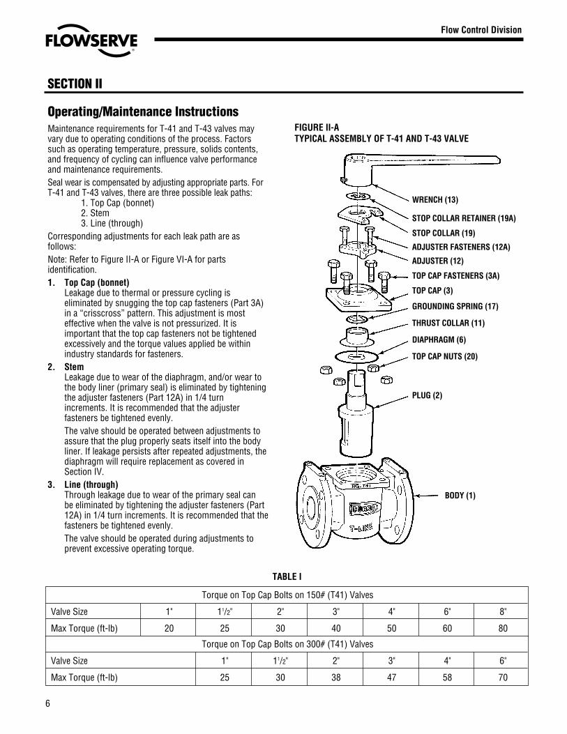
Operating/Maintenance InstructionsMaintenance requirements for T-41 and T-43 valves mayvary due to operating conditions of the process. Factorssuch as operating temperature, pressure, solids contents,and frequency of cycling can influence valve performanceand maintenance requirements.Seal wear is compensated by adjusting appropriate parts. ForT-41 and T-43 valves, there are three possible leak paths:
1. Top Cap (bonnet)2. Stem3. Line (through)
Corresponding adjustments for each leak path are asfollows:Note: Refer to Figure II-A or Figure VI-A for partsidentification.1. Top Cap (bonnet)
Leakage due to thermal or pressure cycling iseliminated by snugging the top cap fasteners (Part 3A)in a “crisscross” pattern. This adjustment is mosteffective when the valve is not pressurized. It isimportant that the top cap fasteners not be tightenedexcessively and the torque values applied be withinindustry standards for fasteners.
2. StemLeakage due to wear of the diaphragm, and/or wear tothe body liner (primary seal) is eliminated by tighteningthe adjuster fasteners (Part 12A) in 1/4 turnincrements. It is recommended that the adjusterfasteners be tightened evenly.The valve should be operated between adjustments toassure that the plug properly seats itself into the bodyliner. If leakage persists after repeated adjustments, thediaphragm will require replacement as covered inSection IV.
3. Line (through)Through leakage due to wear of the primary seal canbe eliminated by tightening the adjuster fasteners (Part12A) in 1/4 turn increments. It is recommended that thefasteners be tightened evenly.The valve should be operated during adjustments toprevent excessive operating torque.
SECTION II
6
Flow Control Division
Section 1.0
FIGURE II-ATYPICAL ASSEMBLY OF T-41 AND T-43 VALVE
WRENCH (13)
STOP COLLAR RETAINER (19A)
STOP COLLAR (19)
ADJUSTER FASTENERS (12A)
ADJUSTER (12)
TOP CAP FASTENERS (3A)
TOP CAP (3)
GROUNDING SPRING (17)
THRUST COLLAR (11)
DIAPHRAGM (6)
TOP CAP NUTS (20)
PLUG (2)
BODY (1)
TABLE I
Torque on Top Cap Bolts on 150# (T41) Valves
Valve Size 1" 11/2" 2" 3" 4" 6" 8"
Max Torque (ft-lb) 20 25 30 40 50 60 80
Torque on Top Cap Bolts on 300# (T41) Valves
Valve Size 1" 11/2" 2" 3" 4" 6"
Max Torque (ft-lb) 25 30 38 47 58 70

Valve Disassembly – T-41, T-43IntroductionNo regular maintenance is required for the T-41 and T-43 valveother than the adjustments covered in Section II. Should itbecome necessary to disassemble the valve for cleaning orother reasons, the following procedures should be followed.Recommended Precautionary Measures1. Valves must be relieved of process fluid and pressure prior
to disassembly.2. Personnel performing disassembly must be suitably pro-
tected and alert for emission of hazardous process fluid.Disassembly StepsNOTE: Refer to Figure II-A for parts identification. If anactuator or gearbox operates the valve, alignment marksshould be noted to assure correct orientation whenreassembled. This may best be accomplished by makingmatching marks on the plug stem and operator housingwhile checking to assure that no burrs are present on theplug stem. Whenever the valve has been disassembled forany reason, the PTFE diaphragm, Part #6, must be replacedwith a new component.
1. Gradually loosen adjuster fasteners (Part 12A) – DO NOTREMOVE.
2. Turn plug (Part 2) in order to raise the plug to vent anymaterial trapped in the valve (see note below).Note: If there is no upward movement of the plug (Part2), it will be necessary to devise a method of lifting theplug upward. This may require removal of the valveoperator (Step 3). This operation should be undertakennoting the above precautionary measures. Methods ofplug removal must include protective measures on plugstem and plug end. Flange protectors should be used toprevent possible spray of material out of the ends whenpressure is relieved from under the plug.
3. WARNING: Do not loosen or remove top cap fasteners(Part 3A) when removing an operator or accessory.Remove the operator by unfastening it from the bracket.
4. Once the plug (Part 2) has lifted, the adjuster fasteners(Part 12A) can be completely removed.
5. Gradually loosen but DO NOT REMOVE all of the top capfasteners (Part 3A). Turn the plug until it is loose and allpressure has been vented. (Again, it may be necessary touse a mechanical means to move the plug upwards.)
6. Remove the top cap fasteners (Part 3A) and top cap(Part 3) from the plug stem (Part 2).
7. Remove the plug (Part 2) from the body (Part 1).8. Remove the grounding spring (Part 17) and thrust collar
(Part 11) from plug stem (Part 2).9. Remove the diaphragm (Part 6) from plug stem (Part 2).
10. Inspect the body liner for wear or damage, especiallyscratches near the top, bottom, and port areas. If wear ordamage is excessive, the valve should be replaced.
SECTION III SECTION IV
Valve Assembly1. The diaphragm (6) is assembled over the plug stem with
the aid of the T4 diaphragm guide, part series #BY77543A1/2"-3/4" #BY77543, 1"-8" #BY79581 (Figure IV-A). The plugstem and diaphragm guide should be checked for nicksbefore installing the diaphragm. Nicks on these surfacescould result in scratches on the lip of the diaphragm.
2. The thrust collar is then assembled over the plug stem anddriven into place through the use of the thrust collar guide,part series #BY77545A, and an arbor press (Figure IV-B).
3. Place the grounding spring (17) over the plug stem.4. Place the top cap (3) and adjuster (12) over the plug stem.
The adjuster fasteners should be threaded into the top capuntil flush with the bottom (Figure IV-C).
Flow Control Division
Section 1.0
If damaged the plug taper and 1/2" in length of stemmust be repolished to a surface finish of 32AA on thetaper and 63AA on stem.
FIGURE IV-A
FIGURE IV-B
7
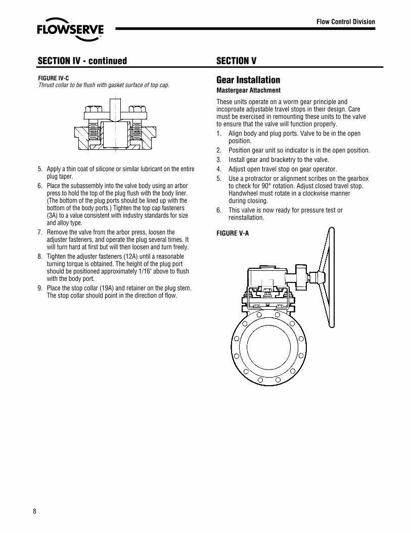
Gear InstallationMastergear Attachment
These units operate on a worm gear principle andincoproate adjustable travel stops in their design. Caremust be exercised in remounting these units to the valveto ensure that the valve will function properly.1. Align body and plug ports. Valve to be in the open
position.2. Position gear unit so indicator is in the open position.3. Install gear and bracketry to the valve.4. Adjust open travel stop on gear operator.5. Use a protractor or alignment scribes on the gearbox
to check for 90° rotation. Adjust closed travel stop.Handwheel must rotate in a clockwise mannerduring closing.
6. This valve is now ready for pressure test orreinstallation.
FIGURE V-A
SECTION VSECTION IV - continued
8
Flow Control Division
Section 1.0
5. Apply a thin coat of silicone or similar lubricant on the entireplug taper.
6. Place the subassembly into the valve body using an arborpress to hold the top of the plug flush with the body liner.(The bottom of the plug ports should be lined up with thebottom of the body ports.) Tighten the top cap fasteners(3A) to a value consistent with industry standards for sizeand alloy type.
7. Remove the valve from the arbor press, loosen theadjuster fasteners, and operate the plug several times. Itwill turn hard at first but will then loosen and turn freely.
8. Tighten the adjuster fasteners (12A) until a reasonableturning torque is obtained. The height of the plug portshould be positioned approximately 1/16" above to flushwith the body port.
9. Place the stop collar (19A) and retainer on the plug stem.The stop collar should point in the direction of flow.
FIGURE IV-CThrust collar to be flush with gasket surface of top cap.

SECTION VI
Flow Control Division
Section 1.0
Recommended Spare Parts & Parts List for T-41 and T-43
Item No. Description T-41 Material Req’d.1 Body Ductile Iron/TFE 12 Plug Ductile Iron/PFA 13 Cap, Top Ductile Iron 1
3A Fasteners, Top Cap Carbon Steel 4A193-B7
6* Diaphragm* PFA 111 Collar, Thrust Durcomet 100 112 Adjuster Durcomet 100 1
12A Fasteners, Adjuster Carbon Steel 2A193-B7
17 Spring, Ground 302 SS 119 Collar, Stop Cadmium Plated 1
Carbon Steel19A Retainer, Collar 302 SS 120 Hex Nuts, Top Cap Carbon Steel 4
A194-2H
Item No. Description T-43 Material Req’d.1 Body Carbon Steel/TFE 12 Plug Ductile Iron/PFA 13 Cap, Top Durcomet 100 1
3A Fasteners, Top Cap Carbon Steel 4A193-B7
6* Diaphragm* PFA 111 Collar, Thrust Durcomet 100 112 Adjuster Durcomet 100 1
12A Fasteners, Adjuster Carbon Steel 2A193-B7
17 Spring, Ground 302 SS 119 Collar, Stop Cadmium Plated 1
Carbon Steel19A Retainer, Collar 302 SS 120 Hex Nuts, Top Cap Carbon Steel 4
A194-2H
*Recommended spare parts
NOTE:Body liners are not field replaceable.
Special ServicesFor the convenience of our valve customers, Flowserve main-tains a complete valve repair facility in our Cookeville, TNfactory. For information on how to capitalize on this serviceplease call us at (931) 432-4021.
9

SECTION VI
Flow Control Division
Section 1.0
Recommended Spare Parts & Parts List for ST-41 and ST-43
Item No. Description ST-41 Material Req’d.1 Body 316SS/TFE 12 Plug 316SS/PFA 13 Cap, Top CD4M 1
3A Fasteners, Top Cap SS 4A193-B840
6* Diaphragm* PTFE 111 Collar, Thrust Durcomet 100 112 Adjuster Durcomet 100 1
12A Fasteners, Adjuster SS 2A193-B840
17 Spring, Ground 302 SS 119 Collar, Stop Cadmium Plated 1
Carbon Steel19A Retainer, Collar 302 SS 120 Hex Nuts, Top Cap SS 4
A194-8
Item No. Description ST-43 Material Req’d.1 Body 316SS/TFE 12 Plug 316SS/PFA 13 Cap, Top CD4M 1
3A Fasteners, Top Cap SS 4A193-B840
6* Diaphragm* PTFE 111 Collar, Thrust Durcomet 100 112 Adjuster Durcomet 100 1
12A Fasteners, Adjuster SS 2A193-B840
17 Spring, Ground 302 SS 119 Collar, Stop Cadmium Plated 1
Carbon Steel19A Retainer, Collar 302 SS 120 Hex Nuts, Top Cap SS 4
A194-8
*Recommended spare parts
10


Or Consult Your Local Stocking Distributor
A T O M A C
Flowserve has the answer to your corrosion resistant, quarter-turn valving needs.
Printed in U.S.A.December 2002
© Flowserve Corporation
Clockwise from top right.
Durco® BTV-2000PTFE or UHMWPE lined chemical service valve
Atomac®
Lined ball valves• ANSI/ISO, standard and full port• Specialty valves• Valve products and accessories
Durco® Sleeveline®
Non-lubricated, PTFE-sleeved plug valves• G4 Isolation• G4E – DIN Mounting Pad• G4 Marathon™• TSG4 Severe Service
Durco® T-Line®
Non-lubricated, PTFE-lined plug valves
Big Max® ButterflyHigh performance valves
Durco® Microfinish™Alloy ball valves
Automax®
Valve automationsystems• Actuators• Controls with
smart technology• Accessories
For more information, contact:
Flowserve CorporationFlow Control Division1978 Foreman DriveCookeville, Tennessee 38501Phone: 931 432 4021Fax: 931 432 3105www.flowserve.com
Flowserve Pte. Ltd.12 Tuas Avenue 20Republic of Singapore 638824Phone: 65 862 3332Fax: 65 862 2800
Flowserve Ahaus GmbHVon Braun Straße 19aD-48683 AhausGermanyPhone: +49 2561 686-0Fax: +49 2561 686-39