Embed Size (px)
Citation preview

Spencer®
Single-StageScroll Blowers
Installation, Operation andMaintenance Instructions
ImportantRead and become familiar with this manual prior to uncrating and installing your Spencer Scroll Blower. Following the instructions detailed here will help you realize its full potential of efficient service and extended lifespan. Damage result-ing from failure to follow correct procedure will void the warranty.
The Spencer Turbine Company Windsor, Connecticut 06095 Form FF12.1
Serial No:
Model No:

2The Spencer Turbine Company ◆ 600 Day Hill Road, Windsor, CT 06095 ◆ TEL 800-232-4321 ◆ 860-688-8361 ◆ www.spencerturbine.com
Note: For complete warranty information, including our limitation of liability, consult Spencer’s Terms and Conditions of Sale - Form 706.
Contents Page I General Instructions .............................................. 2 II Operation and Adjustments ....................................5 III Typical Scroll Blower ............................................. 7 IV Replacement Parts ................................................ 9 V Lubrication Instructions ...........................................9 VI Trouble Shooting Guide ...................................... 10
Before proceeding with this set-up, refer to the machine nameplate and record the machine number and serial number in the boxes on the manual front cover.
I. General Instructions
ImportantRead and become familiar with this manual prior to uncrating and installing or storing machinery – it is a precision piece of equipment capable of extended service and lifespan. Realization of this potential can best be achieved through proper handling and adherence to the following instructions. Damage resulting from failure to follow correct procedures will void warranty.
Spencer ServiceSpencer service begins upon receipt of your request for equipment purchase. Our engineers welcome the opportunity to discuss your problems and will assist in determining specification requirements if so desired. To serve you promptly, we maintain a large inventory of electric motors and machine parts. Also, by combining under one roof the constantly supervised manufacturing, assembly, and test procedures, Spencer can assure you of a unit capable of optimum performance under the most severe service conditions. All Spencer machines are factory tested for load capacities and vibrational characteristics. This assures long, trouble-free operations.
WarrantyWe warrant that this product will be free from defects in material and workmanship for a period of 18 months from date of shipment or 12 months from date of startup, whichever comes first. Within the warranty period, we shall repair or replace, F.O.B. our Factory or designated service center, such products that are determined by us to be defective.
This warranty will not apply to any product which has been subjected to misuse, negligence, or accident or, misapplied or improperly installed. This warranty will not apply to any product which has been disassembled, repaired or otherwise altered by any persons not authorized by our Service Department.
The guarantee of the motor, control, and component manufacturers govern the extent of our guarantee on such equipment. Warranty work on motors, controls, and components must be authorized by Spencer and must be performed in an authorized shop as designated by the motor, control, and component manufacturers. The Spencer Turbine Company reserves the right to invoice all expenses incurred when repairs are made in the field at the specific request of the customer.
HandlingThis machine has been carefully balanced and tested at our factory. It is essential that it be handled with care during installation in order that you may be assured satisfactory performance.
StorageCaution: If machine is to be stored for an extended period of time, it must be carefully protected from dampness, dirt and vibration. The inlet and discharge should be covered to keep foreign matter out; the motor shaft should be periodically rotated a few times by hand. Failure to comply with any of the preceeding will void warranty.
LocationCaution: Do not locate unit in excessively hot area (> 104 ˚F) unless equipment is designed for this condition.
Before placing the machine in its operating position, be sure that the blower and motor are readily accessible for servicing by allowing several feet of clear space around the machine. Inaccessibility can prove costly in both time and labor.
FoundationNo special foundation is necessary for the Scroll Blower. A level concrete f loor or block is recommended, although any other substantial floor will prove satisfactory. The blower should be placed on cork isolating pads furnished. The blower should not be vertically, or “wall” mounted.
TubingAll tubing should be of ample size to minimize frictional loss. It is absolutely essential that all joints be airtight and that there be no leaks in the system. Leaky air pipes consume a surprising amount of power and impair the operating efficiency of the machine. Piping should be properly supported without producing any stress or strain on the machine casing. It is further recommended that the rubber or isolation sleeve supplied with the machine be used to connect it to the tubing system.

3The Spencer Turbine Company ◆ 600 Day Hill Road, Windsor, CT 06095 ◆ TEL 800-232-4321 ◆ 860-688-8361 ◆ www.spencerturbine.com
The rubber connecting sleeve supplied with the scroll should be installed so that it covers a gap of approximately one inch as illustrated. The mounting clamps supplied with the sleeve should be adequately tightened to effect an air-tight connection.
ElectricalCaution: Be sure motor, starter, controls and other electrical equipment is the proper type suitable for the application and environment and complies with all applicable codes.
Be sure that the motor furnished with this machine is wound for the same type of voltage available at the installation site. In making the electrical connections, follow the wiring instructions furnished. Wire and fuses should be of ample capacity to insure that proper voltage is maintained at the motor terminals while starting and running. It is important that proper starting equipment be used. All AC machines should be equipped with a magnetic contactor or a manual or automatic compensator depending on the machine size and the installation regulations of the local power company. The starters should have thermal overload protection as well as true low-voltage protection.
Air FiltersThe Spencer Turbine Company recommends the use of inlet air filters on all Scroll Blowers for pressure applications.
The use of any type of filter requires that it be kept clean to prevent excessive pressure drop in the lines. The dry element of the Spencer filter may be cleaned with soap & water and reused.
Silencers and Combination Filter-SilencersSpencer offers silencers and combination filter-silencers for intake discharge, and bleed applications. The silencers should be properly supported at both ends. Rigid connection to the machine is not recommended. The tubing mount is recommended and connects to the machine with a rubber sleeve and a flange to tubing adapter.
This diagram shows the available discharge positions, viewed from the intake end, and the direction of blower rotation associated with each discharge position.
Coupling AlignmentThe coupling on this machine was carefully aligned at the factory and the coupling halves and shell(s) marked to indicate optimum relative position. However, transportation may have caused coupling misalignment.
Caution: Check the motor and blower shafts for misalignment and carefully realign them if necessary after Installation and before startup, as misalignment can cause destructive vibration. Coupling alignment should be rechecked again after an hour's operation. Final alignment should be made at average operating temperature. After each alignment check, add lubricant per instructions and replace coupling guard.
WARNING: DISCONNECT AND LOCK OUT ELECTRICAL POWER BEFORE PERFORMING ALIGNMENT.
On certain blowers, the coupling is disassembled after factory alignment and marking. The coupling halves are specially protected against the elements during shipping. Prior to startup, assemble the coupling, align keyways using factory markings and lubricate as instructed.
Rubber Inlet and Outlet Sleeve Vacuum ApplicationsWhen the machine is used for vacuum, the outlet should discharge outdoors (preferred) or into a room having ample volume and proper ventilation in order to permit the air to escape and at the same time keep the unit at a reasonable temperature. Intake air must be kept clean through proper filtration methods.
Motor RotationThe motor must be wired correctly to rotate the blower in the right direction. A rotation arrow is located on the blower housing. "Bump" or jog the start button and observe the direction of rotation of the motor shaft. This movement must agree with the rotation arrow. If the rotation is incorrect, the motor wiring must be changed.

Coupling alignment lines up the motor shaft and blower shaft in horizontal and vertical planes. It also ensures an adequate clearance (gap) between the two coupling halves. Only qualified personnel should attempt to align a coupling. If problems arise, contact Spencer or your Spencer Representative.
Sier Bath Gear-Type Couplings, manufactured to our rigid specifications, are most commonly supplied with Spencer equipment.
Sier Bath Hub to Hub Coupling Size, In. Gap, ln. 7/8 1/8 1-1/2 1/8 2 1/8 2-1/2 1/4 3 1/4 3-1/2 1/4 4 1/4 4-1/2 1/4 5 1/4
Remove one snap ring and slide the sleeve off the hub halves. Using a feeler gage, verify that the gap between the coupling halves agrees with this table.
Caution: Some motor shafts are spring-loaded axially. Be careful when using the feeler gage to avoid compressing the shaft and disturbing the normal at-rest position.
Machinery Soft FootImperfections or unevenness between the machine base and any foot of the motor or blower creates a condition known as soft foot, which may be parallel or angular. If uncorrected, soft foot leads to increased stress and high vibration. Although both the motor and blower feet were preset at the factory, each foot must be checked for soft foot prior to alignment. Any vertical or angular soft foot that exceeds .003" is excessive and must be corrected.
Laser Alignment Technique (Recommended)Laser systems have significant advantages such as reduced maintenance costs and energy consumption; prolonged life for bearings, seals and couplings; decreased bearing temperatures and lower vibration levels. Many laser systems also identify and measure soft foot conditions.
NOTE: Consult an alignment specialist if laser equipment is not available.
Reverse Indicator Method (Permissible)This method may be done electronically following the instrument manufacturer's instructions or by means of dial indicators as follows:
1. Reinstall the coupling sleeve, seal and snap ring.
2. Clamp dial indicators on shafts 180° apart as shown.
3. Place indicator probes on opposite shafts as shown.
4. Rotate both shafts simultaneously in the correct operating direction, taking readings at 90° intervals.
5. Adjust motor to achieve parallel and angular alignment. If questions arise, contact the Spencer Service Department.
Straightedge Method (Permissible)1. Remove old lubricant and clean the hub teeth.
2. Set a machine shop quality straightedge across the coupling hubs (at the root diameter of the gear teeth).
3. Adjust the motor so the straightedge is evenly supported between the coupling hubs at the 3, 6, 9 and 12 o'clock positions.
4. Using a feeler gage, measure the clearance between the coupling hubs at the 3, 6, 9 and 12 o'clock positions.
5. Adjust the motor so the gap is identical at all four positions and in accord with the table of hub to hub gaps.
4The Spencer Turbine Company ◆ 600 Day Hill Road, Windsor, CT 06095 ◆ TEL 800-232-4321 ◆ 860-688-8361 ◆ www.spencerturbine.com

caused by operating in surge is not covered by Spencer warranty.
A blower In surge produces a rush or pulsating rhythmic air sound caused when airflow into or out of the blower is restr icted. In addit ion to i ts characteristic noise, surge may be detected by power or pressure fluctuations. Surge is destructive because i t is accompanied by excessive temperatures and aerodynamic forces that will ultimately cause mechanical failure. A surge condition is simply eliminated by increasing the airflow either into the system or to a bypass or vent.
NOTE: If a blower surges violently at startup, avoid recurrences by leaving the throttling valve open at or near its normal operating position.
II. Operation and AdjustmentsStartup PrecautionsBefore operating a new blower for the first lime, review its installation and setup to be sure that no steps have been overlooked.
1. Installation Check List• Is there any damage from transportation or
installation?
• Isthemachinelevel?
• Have all packing, shippingmaterials and toolsbeen removed?
• Istheinletfilterinplace?
• Areisolationpadsinplace?
• Isthepipingconnectedandsupported?
• Are flexible connectors in place betweenblowerand piping?
• Aresafetyguardsinplace?
2. Adjustment Checks• Is the coupling aligned within tolerances and
lubricated?
3. Operational Checks• Is the throt tl ing valve closed or properly
positioned?
• Dotheblowershaftanddriverspinfreely?
• Istheisolationvalve(ifany)open?
• Isthesystemreadyforairorgasdelivery?
• Hasmotorrotationbeenchecked?
• Aremotor and electrical accessories properlywired?
5
Coupling Alignment with Sleeve Bearing MotorsCaution: Complete the following procedures before attempting coupling alignment with sleeve bearing motors.
Use a flange-type gear coupling for both 1800 and 2600 RPM motors. Do not use a sleeve-type coupling.
Sleeve bearing motors have a specified end play. End play limits and the magnetic center (where motor will run) should be scribed on the shaft by the manufacturer.
Use the following procedure to align a sleeve bearing motor with a blower.
1. Make sure the motor shaft is level.
2. Position the motor so that when the rotor is pushed toward the blower as far as it will go, there will 0.030" clearance between the ends of the motor and blower shafts (or the alignment faces on the coupling hubs).
3. Proceed with coupling alignment using the appropriate instructions.
Alignment Tips• Makesuretheblowerislevelbeforealignment.
• Mark the axial location of the motor beforealignment as a reference point to be sure it does not move.
• Avoiddisturbinganyfactory-installedshimsunlessthey are to be replaced.
• Dosoft footcorrections first; loosenallmountingbolts before correcting any foot.
• During the final vertical adjustment of themotor,work on one side at a time, loosening the jack bolts first so the motor does not move laterally as mounting bolts are loosened.
• Use the smallest shim that will slide over themounting bolts.
• Minimize the number of shims.One thick shimand 2-3 thin shims are usually satisfactory.
• Remove all traces of dirt or contaminants fromshims and machine parts.
• Usestainlesssteelshimsonly.
• Neverreuseshims.
Caution: After each alignment check, add coupling lubricant If required.
WARNING: REPLACE THE COUPLING GUARD BEFORE RESTARTING THE BLOWER.
SurgeCaution: Do not operate blower In surge (unstable low flow range). Damage to blower
The Spencer Turbine Company ◆ 600 Day Hill Road, Windsor, CT 06095 ◆ TEL 800-232-4321 ◆ 860-688-8361 ◆ www.spencerturbine.com

6
Instructions for Disassembly and ReassemblyCaution: Parts must be reassembled in exactly the same relative positions. Therefore, it is recommended that each part be tagged as it is removed from the machine to facilitate later reassembly. It is especially important that the impeller location and its position on the shaft be marked.
BalancingEach machine is fully tested before leaving the Spencer factory to be sure vibrations, if any, are well within specifications for that particular machine. However, rough handling during shipment or improper disassembly/reassembly of a machine can upset its balance and result in excess vibration.
When a machine is being disassembled for repairs, mark the parts as they are removed. If this is done, no trouble should be expected from vibration when they are reassembled in the same order.
However, if the impeller is being replaced or there is any vibration due to an unbalanced condition after assembly, use the following procedure.
Run the unit at maximum speed. Mark the position of the impeller hub on the shaft. Loosen the bolts or screws holding the impeller on the shaft. Rotate the impeller 90˚ on the shaft. Run the machine again at the maximum speed, and check the vibration. Repeat this process until the best position is located for the impeller on the shaft so that there is no vibration or unbalance in the machine.
DisassemblyScroll blowers are now being supplied with casing, motor base and casing/base support welded into a integral unit. This innovation provides a stable and maintenance free platform. As a result, maintenance is confined to removal of the motor on one end and
• Isthecontrolpanelenergized?
• Have maintenance and operations personnelbeen notified?
CAUTION: This blower must have adequate system resistance at all times to avoid operation at or near free delivery (wide open). It Is typically imposed by the process and supplemented with a throttling valve. Running the blower overloaded will damage the motor.
Start UpCaution: It is very important that the blower be installed with regard to the correct direction of rotation. A direction-of-rotation arrow is affixed to the scroll casing.
Under no circumstances should the Scroll Blower be operated without being connected to the pipe system with which it is to be used.
When star ting up a Scroll Blower it is recommended that the blast gate or other control device be closed. When first starting the installation, an ammeter should be connected to the motor circuit and the control device opened until full load current is reached. At this point, the unit is delivering the full rated volume of air for which it was designed and the control device should be adjusted to prevent opening beyond this point. (See following paragraphs.)
Multiple Machine OperationCaution: All Scroll Blowers in a multiple machine operation should be operated periodically. This can be accomplished through bi-weekly, alternate operation of the machines.
Check valves must be installed in the discharge of each Scroll Blower to prevent blow-back through the unit not in operation. These are available as optional equipment.
When operating two or more Scroll Blowers in parallel it is necessary to be sure that each machine carries its respective share of the load. This is accomplished by setting each blast gate so that the Scroll Blower operates within the full load amp rating of its motor. Once the proper setting is established, tighten bolts securing the variable stop (View A) or the locking nut (View B). This prevents the blast gate from being opened beyond the full load rating of the motor.
The Spencer Turbine Company ◆ 600 Day Hill Road, Windsor, CT 06095 ◆ TEL 800-232-4321 ◆ 860-688-8361 ◆ www.spencerturbine.com

3
9
12
14
17
III. Typical Scroll BlowerNote:
1. The impeller is equipped with a split clamped hub or a tapered bushing clamp (as illustrated). The latter is tightened on the shaft with three or six Allen socket screws.
2. Contact Spencer for separate instructions for arrangement 9 (Belt Drive) single-stage Scroll Blowers.
Screened items are recommend-ed spare parts 1 - Front Motor End Bracket 2 - Discharge Flange 3 - Impeller 4 - End Head 5 - Impeller Allen Screws 6 - Motor Shaft 7 - Inlet 8 - End Head Bolts 9 - End Head Gasket 10 - Motor Housing Assembly (Casing, Motor Base, Floor Support) 11 - Division Head Packing 12 - Rear Motor Bearing 13 - Motor Bolts 14 - Front Motor Bearing 15 - Thrust Bearing Nut 16 - Front Bearing End Cap 17 - Motor Shim
removal of the end head on the other. Removal of the end head provides immediate access to the impeller.
To disassemble the scroll blower, proceed as follows: Remove the bolts (8) securing end head (4) to the casing assembly. Remove the end head.
Measure or mark position of impeller on the shaft, loosen the three (or six) Allen socket screws three full turns, tap the heads of the screws. This will loosen the impeller from the tapered bushing allowing removal.
Remove the bolts holding the motor in place. Remove motor leaving the block and shims in their original place. The motor can now be overhauled. It is good maintenance practice and Spencer recommends replacing the division head packing (11) when motor removal /re insta l lat ion is accomplished.
ReassemblyReplace motor in original position on blocking and shims, making sure that shaft is centered in hole in division head and taking care not to damage packing (11). Be sure motor is perpendicular to division head so that fan is properly aligned within the casing. Tighten motor hold-down bolts finger tight. Replace fan and tighten Allen socket screws. Determine (by hand) that fan turns freely without interference. Without causing the motor to move, tighten motor hold-down bolts securely.
Replace end head gasket and end head in proper position. Insert all bolts. Then tighten uniformly. Machine is ready to run.
Check that motor leads are properly connected and motor is rotating in the right direction.
7The Spencer Turbine Company ◆ 600 Day Hill Road, Windsor, CT 06095 ◆ TEL 800-232-4321 ◆ 860-688-8361 ◆ www.spencerturbine.com
BP - Balancing PointLP - Lifting Point (Half-moon cutouts in Scroll floor support)

12
3
4
5
6
7
9
8
8
Recommended spare parts1 - Flexible Coupling2 - Coupling End Bearing3 - Blower End Bearing4 - Division Head Packing5 - Shaft6 - Impeller7 - End Head Gasket8 - Drive End Motor Bearing9 - Opposite Drive End Motor Bearing
Arrangement 8: Four-Bearing Overhung Design
The Spencer Turbine Company ◆ 600 Day Hill Road, Windsor, CT 06095 ◆ TEL 800-232-4321 ◆ 860-688-8361 ◆ www.spencerturbine.com

V. Lubrication Instructions WARNING: DISCONNECT AND LOCK OUT ELECTRICAL POWER BEFORE PERFORMING LUBRICATION.
Motor BearingsFollow the motor manufacturer's recommendations. Some motors are equipped with sealed bearings not intended for relubrication; these motors have no grease or drain plugs.
Blower Bearings (Arrangement 8)Blowers are equipped with deep-groove ball bearings designed to carry the thrust and radial loads. These bearings are packed at the factory with sufficient grease for 1500 to 8000 hours of continuous operation prior to relubrication. Lubrication prior to blower operation is not recommended and should not be attempted.
If, however, the blower has been stored for three months or longer, remove the bearing caps and check for moisture or hard grease. Discard any hard or dry grease and relubricate if necessary.
An average lubrication interval should be established based on existing conditions. Several factors affect the frequency of lubrication:
1. Operating temperature of the bearing2. Indoor or outdoor blower location3. Clean or dusty conditions4. Ambient temperature5. Predicted duty cycle6. Bearing size and speed
Under actual operating conditions, the ideal lubrication interval of 8000 hours should be adjusted according to the following table.
NOTE: The higher limit of each range shown is for small bearings (#308 and smaller); the lower limit is for large sizes. This table is only a guide. An extremely dirty atmosphere could decrease the lubrication interval as much as 50%.
Operating Condition Lubrication Interval
I 1. 120-150 °F bearing temp. 4000-6000 hours 2. Indoor installation 3. Clean atmosphere 4. 40-100 °F ambient temp. 5. Continuous operation
II Same conditions as I 6000-8000 hours except Intermittent operation
III 1. 120-155 °F bearing temp. 3000-5000 hours 2. Outdoor installation 3. All atmospheres 4. 0-104 °F ambient temp. 5. Continuous operation
IV Same conditions as III 5000-7000 hours except intermittent operation
IV. Replacement Parts How to order replacement partsWhen ordering replacement parts, it is important that the information you furnish to Spencer is correct. Be sure when reading nameplates that you obtain the correct information. Remember, the more complete the information, the quicker the order will be processed; incomplete information will result in unnecessary delays and expense through callbacks. When in doubt, consult the factory for further information.
To order replacement parts, furnish the following:1. Machine model and serial number from machine
nameplate.
2. Motor horsepower from motor nameplate.
3. Measure and record the casing diameter.
4. Refer to applicable illustration in the instruction manual and locate needed item by its circled call-out number. Refer to callout list for nomenclature and record.
9The Spencer Turbine Company ◆ 600 Day Hill Road, Windsor, CT 06095 ◆ TEL 800-232-4321 ◆ 860-688-8361 ◆ www.spencerturbine.com

VI. Trouble Shooting GuideTrouble Probable Cause Corrective Action
Insufficient air Low pressure or vacuum as determined by measurement with a manometer:through system – Incorrect rotation. Change motor leads to correct rotation. – Machine sized for requirements given, but air lines too small Increase line sizes or install machine providing higher causing excessive frictional loss. output pressure. – Valves in line, causing excessive losses. Install larger valves or install machine providing higher output pressure. – Inlet or outlet partially blocked, i.e., clogged inlet filter, Check blast gate; remove and repair if necessary. blast gate shaft slipped in handle and shutter does not open fully. – High inlet temperature, i.e., higher than designed inlet Direct inlet line to cooler area; replace machine with temperature. one designed for correct temperature. – Lower inlet pressure, i.e., lower than designed inlet pressure. Remove inlet restrictions or install machine providing higher output pressure. – Machine not running at designed speed. Refer to motor manufacturer’s instructions; check motor speed; check voltage connections. – Lower than design gas density or specific gravity. Check gas analysis; increase density or install machine designed for correct requirements. – Machine air passages clogged with material. Disassemble, clean and inspect all parts. – Fans worn out due to explosion, abrasion, or vibration. Replace fan(s). – Pressure or vacuum gauge inaccurate – would not apply to Calibrate gauge; always use a “U” tube manometer for performance of machine, but to gauge reading only. checking pressure and/or vacuum. Machine design capacity too small for the system: – System requirements incorrectly calculated by customer. Install larger volume or lower vacuum machine to handle correct system requirements. – Too many leaks and/or openings. Locate and repair all leaks. Measuring gas or air flow incorrectly: – Flowmeters incorrectly calibrated. Calibrate flowmeters; be certain proper orifice is used for meter (check with flowmeter manufacturer). – No means of measurement available so customer is Obtain and install flowmeter. guessing at airflow.
Machine noisy Internal machine malfunction: – Fan hitting after customer reassembly and/or fan slipping on Reassemble according to instructions, tighten fan. Bleed air at shaft due to heat or excessive inlet pressure. low flow to reduce heat. Change inlet conditions if necessary. – Fan coming apart due to age or wear from dirty air or gas. Replace fan. – Machine out of balance running rough. Rebalance and/or clean machine (refer to “Machine Vibrating”). – Foreign material in machine. Disassemble machine, inspect and clean. Reassemble and, if necessary, install filter to prevent further clogging.
Motor malfunctions: – Excessive electrical hum or whine. Check motor manufacturer’s instructions. Check voltage supply and connections. – Wrong voltage – low voltage motor not up to speed. High Check for proper voltage at motor and correct. voltage will burn out motor and also cause noticeably more noise. – Bearing failure. Check manufacturer’s instructions and replace if necessary. – Motor rebuilt improperly – thrust taken on wrong end in Rebuild motor properly and correct end play. standard overhung machine. – Worn bearings or loose part. Tighten, repair or replace (check with motor manufacturer). – Low frequency. Separate power supply; correct frequency.
Machine vibrating Imbalance: – Material build-up on Impeller. Clean Impeller; install or improve filter to prevent further build up. – Shaft bent. Replace shaft. – Faulty replacement motor installed and /or machine Disassemble machine, balance motor, reassemble reassembled incorrectly. according to instruction in this book and assembly print. – Motor bearings worn. Replace worn bearings.
Mechanical: – Inlet and/or outlet piping connected to machine without Install flexible connection at inlet and outlet. flexible connector causing torque or strain on casing. – Machine bolted down causing change in alignment. Remove bolts; use dowel pins or set in guide channels. – Piping not properly supported. Properly anchor piping beyond flexible connector. – Improper voltage on motor causing assembly to operate Check voltage and wiring connections; correct voltage. at different speed. – Solids or liquids in, or passing through machine. Disassemble, inspect and clean machine, install or improve filter to prevent further contamination. – Machine not mounted on solid foundation, i.e., on Re-inforce foundation. unstable catwalk, etc.
Motor Hot (Can be Incorrect motor selection:checked with surface – Ambient temperature too high for insulation class. Cool motor or replace with motor having proper insulation.thermometer. Refer – Incorrect voltage. Change to correct voltage.to factory for decision – Incorrect cycle. Change to correct cycle. as to whether or not – Electrical short-circuit insulation failure. Repair or replace motor.it is too hot.) – Motor overloaded – blower too small for system. Install larger motor and/or blower. Unbalanced voltage supply: Check with power company for correction.
10The Spencer Turbine Company ◆ 600 Day Hill Road, Windsor, CT 06095 ◆ TEL 800-232-4321 ◆ 860-688-8361 ◆ www.spencerturbine.com
Spencer Single-stage Scroll Blowers
Standard Features
Optional Features
Flanged outlet with standardANSI B16.5 125lb/150lb drillingfor ease of installation.
• Stainlesssteelorotherspecialmaterials.
• Housingof1⁄4"or3⁄8"steelplate.
• Mechanicalsealforgas-tightconstruction.
• Spark-resistantconstruction.
• Hightemperatureconstructionwithheatslinger.
• Epoxyorothercoatingsforchemicalapplications.
• Customdesigns.
• Specialmotorenclosures–chemicalduty, high-efficiency, explosion-proof.
• Casingdrains.
• Backwardcurvedimpellerstoreducenoiseand increase operating stability at low flows.
• Rotatabledischarge.
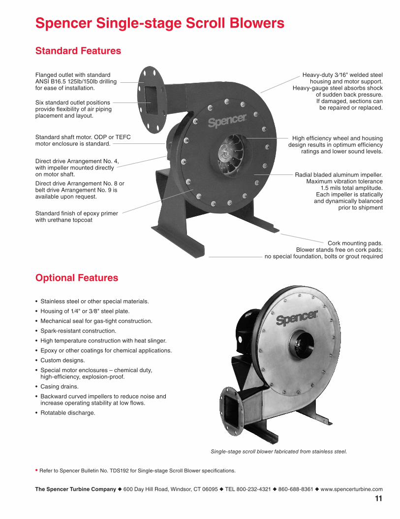
Single-stage scroll blower fabricated from stainless steel.
Heavy-duty3⁄16"weldedsteelhousing and motor support.
Heavy-gauge steel absorbs shockof sudden back pressure.If damaged, sections canbe repaired or replaced.
Radial bladed aluminum impeller.Maximum vibration tolerance
1.5 mils total amplitude.Each impeller is statically
and dynamically balancedprior to shipment
High efficiency wheel and housingdesign results in optimum efficiency
ratings and lower sound levels.
Cork mounting pads.Blower stands free on cork pads;
no special foundation, bolts or grout required
Six standard outlet positionsprovide flexibility of air pipingplacement and layout.
Standard shaft motor. ODP or TEFCmotor enclosure is standard.
Direct drive Arrangement No. 4,with impeller mounted directlyon motor shaft.
Direct drive Arrangement No. 8 orbelt drive Arrangement No. 9 isavailable upon request.
Standard finish of epoxy primerwith urethane topcoat
• Refer to Spencer Bulletin No. TDS192 for Single-stage Scroll Blower specifications.
11The Spencer Turbine Company ◆ 600 Day Hill Road, Windsor, CT 06095 ◆ TEL 800-232-4321 ◆ 860-688-8361 ◆ www.spencerturbine.com

Form FF12.1 Copyright ©2012 The Spencer Turbine Company 041012KBA
Blowers & Vacuum Systems with an Engineering Edge
The Turbine Company, 600 Day Hill Road, Windsor, CT 06095 USA
TEL 800-232-4321 ◆ 860-688-8361 ◆ FAX 860-688-0098 ◆ www.spencerturbine.com
Products & Services
For the name and telephone number of your local Spencer Representative, call 800-232-4321
or email [email protected]
Industrially rated products offering effective solutions for air and gas handling problems:
• Multistagecentrifugalblowers
• Single-stagecentrifugalblowers
• Highspeedturboblowers
• Gasboostersandhermeticgasboosters
• Regenerativeblowers
• Modularcentralvacuumsystems
• Mobileorstationaryintegratedvacuumunits
• Separatorsanddustcollectors
• Custom-engineeredproductswithspecialmaterials for extreme temperatures and pressures
Complementary accessories with single source convenience and compatibility:
• Standardandcustomelectricalcontrolpanels–UL, CUL Listed and C.E. Compliant available
• Valves,gauges,couplings,shrinksleeves,vibration isolators and other system components
• Comprehensiveselectionoftubing,fittings,vacuum hoses, valves and tools
Comprehensive engineering and other customer support services:
• Theindustry’slargestcomplementof technical specialists in air and gas handling technology
• Worldwidepartsandserviceorganization
• Applicationresearchandtestingfacility
Worldwide organization of sales repre-sentatives and distributors offering:
• Productselection,installationandoperationassistance
• Comprehensivesystemdesignservices
• Follow-upservicesandtroubleshooting
Spencer Corporate Headquarters and Manufacturing Plant, Windsor, CT USA