Embed Size (px)
Citation preview

28141 Rev A 10-27-06
Installation, Operation and Maintenance Manual
Oil Fired Warm Air Furnaces
BCL BCL-S BFL
ALL INSTALLATIONS MUST MEET ALL LOCAL, PROVINCIAL/STATE,
AND FEDERAL CODES WHICH MAY DIFER FROM THIS MANUAL
ECR International Ltd. Olsen Division
Read this complete manual before beginning installation. These instructions must be kept with the furnace for future reference. P.O. Box 900, Wallaceburg, Ontario, Canada N8A 5E5
Installation, Operation and Maintenance Manual
FOR YOUR SAFETY: Do not store or use gasoline or other flammable liquids or vapors in the vicinity
of this, or any other appliance.
28141 Rev A 10-27-06 2
Table of Contents 1. INTRODUCTION................................................................................................................................................... 3 2. HEAT LOSS.......................................................................................................................................................... 3 3. LOCATION OF UNIT............................................................................................................................................ 3 4. AIR CONDITIONING APPLICATIONS ................................................................................................................ 3 5. COMBUSTION AIR .............................................................................................................................................. 4 6. CHIMNEY VENTING............................................................................................................................................. 4 7. BAROMETRIC DAMPER CONTROL .................................................................................................................. 4 8. OPTIONAL SIDEWALL VENTING....................................................................................................................... 5 9. FAN AND LIMIT CONTROL................................................................................................................................. 5 10. ELECTRICAL CONNECTIONS.......................................................................................................................... 5 11. HUMIDIFIER ....................................................................................................................................................... 6 12. PIPING INSTALLATION..................................................................................................................................... 6 13. OIL FILTER......................................................................................................................................................... 6 14. OIL BURNER NOZZLES.................................................................................................................................... 6 15. OIL BURNER ADJUSTMENT............................................................................................................................ 6 16. BURNER ELECTRODES ................................................................................................................................... 7 17. BURNER PRIMARY CONTROL ........................................................................................................................ 7 18. COMBUSTION CHAMBER ................................................................................................................................ 7 19. CIRCULATING AIR BLOWER........................................................................................................................... 7 20. MAINTENANCE AND SERVICE........................................................................................................................ 9 21. OPERATING INSTRUCTIONS......................................................................................................................... 10 TABLE A-1: BECKETT AF OIL BURNER SET-UP .............................................................................................. 11 TABLE A-2: AERO HFUS OIL BURNER SET-UP FOR BCL 170 - 225 .............................................................. 11 TABLE A-3: BECKETT AFII BURNER SET-UP FOR SIDE WALL VENTED BCL(S) AND BFL........................ 12 TABLE A-4: WAYNE HSR OIL BURNER SET-UP FOR BCL(S) AND BFL ........................................................ 12 TABLE A-5: RIELLO 40F OIL BURNER SET-UP FOR BCL(S) AND BFL.......................................................... 13 TABLE A-6: RIELLO R35 OIL BURNER SET-UP FOR BCL(S) AND BFL ......................................................... 13 TABLE A-7: RIELLO 40BF OIL BURNER SET-UP FOR SIDE WALL VENTED BCL(S) AND BFL................... 14 A.1 OIL BURNER AIR ADJUSTMENT .................................................................................................................. 14 A.2 BURNER ELECTRODES ................................................................................................................................ 15 A.3 START UP........................................................................................................................................................ 15 A.4 SPECIAL INSTRUCTIONS FOR UNITS EQUIPPED WITH RIELLO BURNERS.......................................... 15 TABLE A-8: DIRECT DRIVE BLOWER SET-UP .................................................................................................. 16 TABLE A-9: BELT DRIVE BLOWER SET-UP ...................................................................................................... 18 TABLE A-10: RECOMMENDED MINIMUM INSTALLATION CLEARANCES (INCHES).................................... 20 TABLE A-11: GENERAL DIMENSIONS (INCHES) .............................................................................................. 20 TABLE A-12: AIRFLOW CHARACTERISTICS – DIRECT DRIVE....................................................................... 21 TABLE A-13: AIRFLOW CHARACTERISTICS – BELT DRIVE........................................................................... 21 TABLE B-1: BECKETT AND RIELLO CHIMNEY VENTED WIRING DIAGRAM BCL(S) / BFL ......................... 23 TABLE B-2: BECKETT AND RIELLO DIRECT VENT WIRING DIAGRAM BCL(S) / BFL ................................. 24 APPENDIX C TROUBLESHOOTING ..................................................................................................................... 25 22. FINAL CHECK OUT ......................................................................................................................................... 28 PARTS LISTING: LOWBOY MODEL: BCL - 190 / 225 ......................................................................................... 30 PARTS LISTING: LOWBOY MODEL: BCL - 120S / 145S .................................................................................... 33 PARTS LISTING: LOWBOY MODEL: BFL - 120 / 145.......................................................................................... 37 HOMEOWNER’S REFERENCE TABLE................................................................................................................. 40 NOTES:.................................................................................................................................................................... 41
28141 Rev A 10-27-06 3
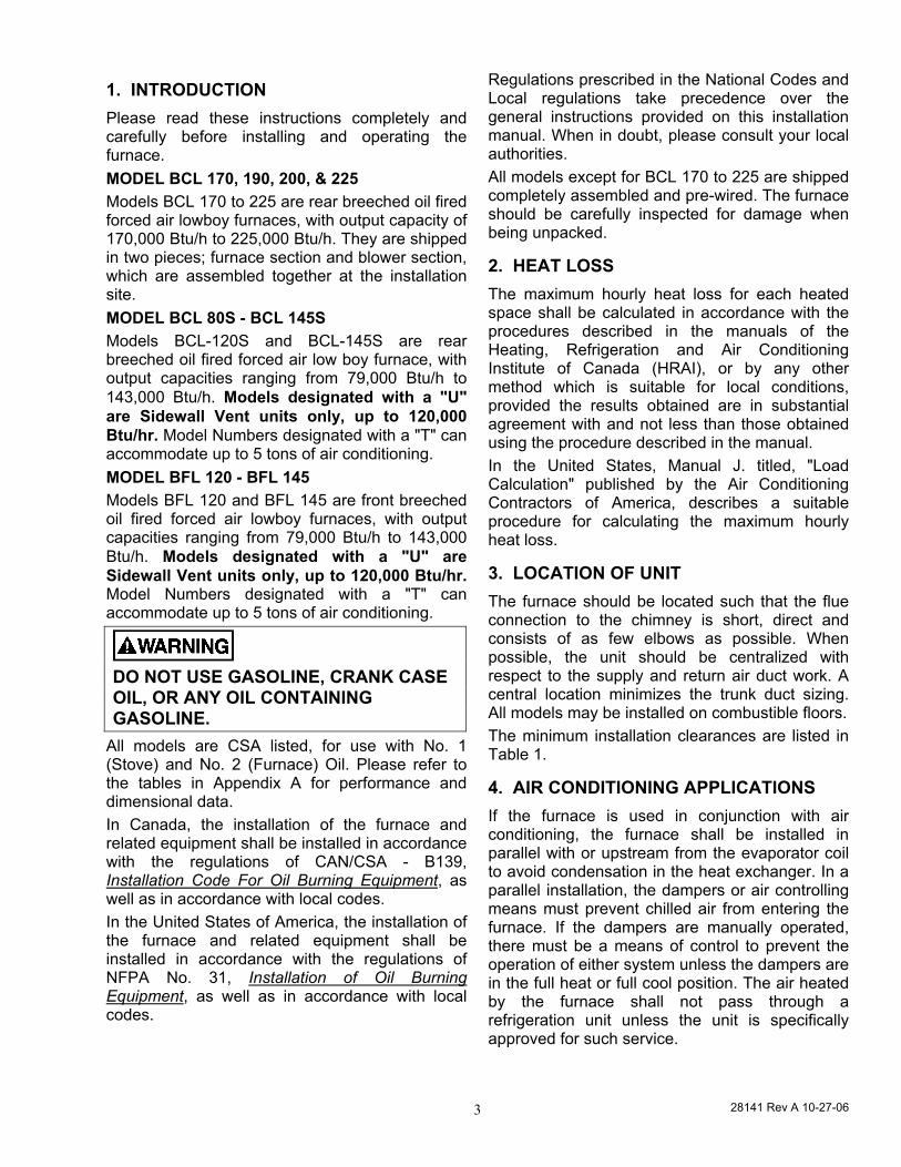
1. INTRODUCTION Please read these instructions completely and carefully before installing and operating the furnace. MODEL BCL 170, 190, 200, & 225 Models BCL 170 to 225 are rear breeched oil fired forced air lowboy furnaces, with output capacity of 170,000 Btu/h to 225,000 Btu/h. They are shipped in two pieces; furnace section and blower section, which are assembled together at the installation site. MODEL BCL 80S - BCL 145S Models BCL-120S and BCL-145S are rear breeched oil fired forced air low boy furnace, with output capacities ranging from 79,000 Btu/h to 143,000 Btu/h. Models designated with a "U" are Sidewall Vent units only, up to 120,000 Btu/hr. Model Numbers designated with a "T" can accommodate up to 5 tons of air conditioning. MODEL BFL 120 - BFL 145 Models BFL 120 and BFL 145 are front breeched oil fired forced air lowboy furnaces, with output capacities ranging from 79,000 Btu/h to 143,000 Btu/h. Models designated with a "U" are Sidewall Vent units only, up to 120,000 Btu/hr. Model Numbers designated with a "T" can accommodate up to 5 tons of air conditioning.
DO NOT USE GASOLINE, CRANK CASE OIL, OR ANY OIL CONTAINING GASOLINE.
All models are CSA listed, for use with No. 1 (Stove) and No. 2 (Furnace) Oil. Please refer to the tables in Appendix A for performance and dimensional data. In Canada, the installation of the furnace and related equipment shall be installed in accordance with the regulations of CAN/CSA - B139, Installation Code For Oil Burning Equipment, as well as in accordance with local codes. In the United States of America, the installation of the furnace and related equipment shall be installed in accordance with the regulations of NFPA No. 31, Installation of Oil Burning Equipment, as well as in accordance with local codes.
Regulations prescribed in the National Codes and Local regulations take precedence over the general instructions provided on this installation manual. When in doubt, please consult your local authorities. All models except for BCL 170 to 225 are shipped completely assembled and pre-wired. The furnace should be carefully inspected for damage when being unpacked.
2. HEAT LOSS The maximum hourly heat loss for each heated space shall be calculated in accordance with the procedures described in the manuals of the Heating, Refrigeration and Air Conditioning Institute of Canada (HRAI), or by any other method which is suitable for local conditions, provided the results obtained are in substantial agreement with and not less than those obtained using the procedure described in the manual. In the United States, Manual J. titled, "Load Calculation" published by the Air Conditioning Contractors of America, describes a suitable procedure for calculating the maximum hourly heat loss.
3. LOCATION OF UNIT The furnace should be located such that the flue connection to the chimney is short, direct and consists of as few elbows as possible. When possible, the unit should be centralized with respect to the supply and return air duct work. A central location minimizes the trunk duct sizing. All models may be installed on combustible floors. The minimum installation clearances are listed in Table 1.
4. AIR CONDITIONING APPLICATIONS If the furnace is used in conjunction with air conditioning, the furnace shall be installed in parallel with or upstream from the evaporator coil to avoid condensation in the heat exchanger. In a parallel installation, the dampers or air controlling means must prevent chilled air from entering the furnace. If the dampers are manually operated, there must be a means of control to prevent the operation of either system unless the dampers are in the full heat or full cool position. The air heated by the furnace shall not pass through a refrigeration unit unless the unit is specifically approved for such service.
28141 Rev A 10-27-06 4
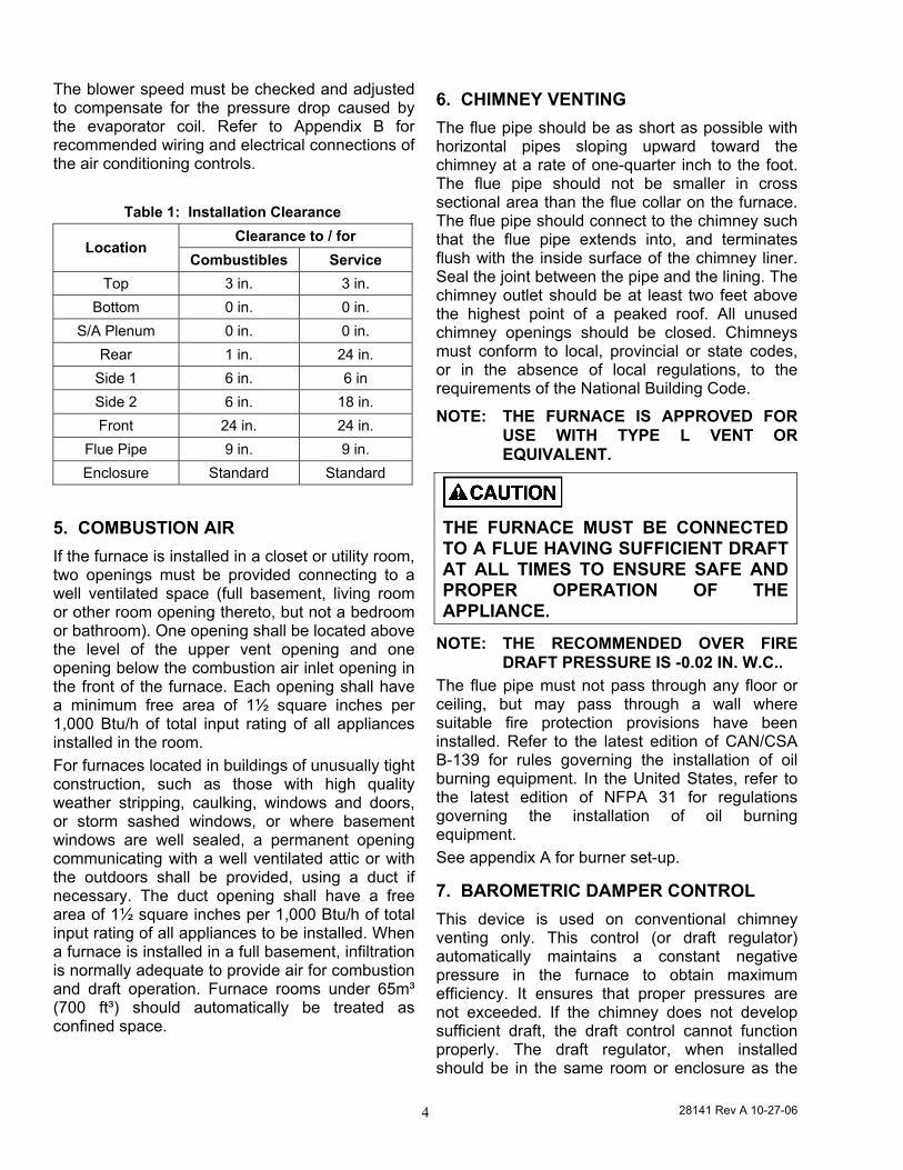
The blower speed must be checked and adjusted to compensate for the pressure drop caused by the evaporator coil. Refer to Appendix B for recommended wiring and electrical connections of the air conditioning controls.
Table 1: Installation Clearance Clearance to / for
Location Combustibles Service
Top 3 in. 3 in. Bottom 0 in. 0 in.
S/A Plenum 0 in. 0 in. Rear 1 in. 24 in.
Side 1 6 in. 6 in Side 2 6 in. 18 in. Front 24 in. 24 in.
Flue Pipe 9 in. 9 in. Enclosure Standard Standard
5. COMBUSTION AIR If the furnace is installed in a closet or utility room, two openings must be provided connecting to a well ventilated space (full basement, living room or other room opening thereto, but not a bedroom or bathroom). One opening shall be located above the level of the upper vent opening and one opening below the combustion air inlet opening in the front of the furnace. Each opening shall have a minimum free area of 1½ square inches per 1,000 Btu/h of total input rating of all appliances installed in the room. For furnaces located in buildings of unusually tight construction, such as those with high quality weather stripping, caulking, windows and doors, or storm sashed windows, or where basement windows are well sealed, a permanent opening communicating with a well ventilated attic or with the outdoors shall be provided, using a duct if necessary. The duct opening shall have a free area of 1½ square inches per 1,000 Btu/h of total input rating of all appliances to be installed. When a furnace is installed in a full basement, infiltration is normally adequate to provide air for combustion and draft operation. Furnace rooms under 65m³ (700 ft³) should automatically be treated as confined space.
6. CHIMNEY VENTING The flue pipe should be as short as possible with horizontal pipes sloping upward toward the chimney at a rate of one-quarter inch to the foot. The flue pipe should not be smaller in cross sectional area than the flue collar on the furnace. The flue pipe should connect to the chimney such that the flue pipe extends into, and terminates flush with the inside surface of the chimney liner. Seal the joint between the pipe and the lining. The chimney outlet should be at least two feet above the highest point of a peaked roof. All unused chimney openings should be closed. Chimneys must conform to local, provincial or state codes, or in the absence of local regulations, to the requirements of the National Building Code.
NOTE: THE FURNACE IS APPROVED FOR USE WITH TYPE L VENT OR EQUIVALENT.
THE FURNACE MUST BE CONNECTED TO A FLUE HAVING SUFFICIENT DRAFT AT ALL TIMES TO ENSURE SAFE AND PROPER OPERATION OF THE APPLIANCE.
NOTE: THE RECOMMENDED OVER FIRE DRAFT PRESSURE IS -0.02 IN. W.C..
The flue pipe must not pass through any floor or ceiling, but may pass through a wall where suitable fire protection provisions have been installed. Refer to the latest edition of CAN/CSA B-139 for rules governing the installation of oil burning equipment. In the United States, refer to the latest edition of NFPA 31 for regulations governing the installation of oil burning equipment. See appendix A for burner set-up.
7. BAROMETRIC DAMPER CONTROL This device is used on conventional chimney venting only. This control (or draft regulator) automatically maintains a constant negative pressure in the furnace to obtain maximum efficiency. It ensures that proper pressures are not exceeded. If the chimney does not develop sufficient draft, the draft control cannot function properly. The draft regulator, when installed should be in the same room or enclosure as the
28141 Rev A 10-27-06 5
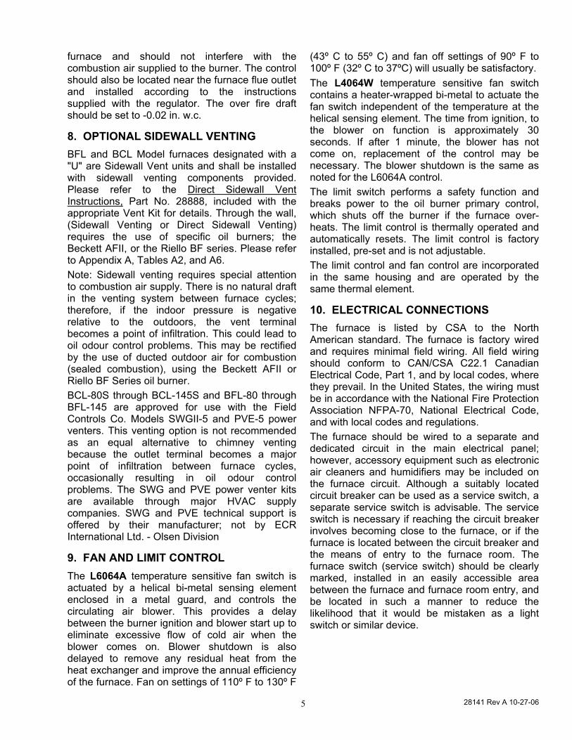
furnace and should not interfere with the combustion air supplied to the burner. The control should also be located near the furnace flue outlet and installed according to the instructions supplied with the regulator. The over fire draft should be set to -0.02 in. w.c.
8. OPTIONAL SIDEWALL VENTING BFL and BCL Model furnaces designated with a "U" are Sidewall Vent units and shall be installed with sidewall venting components provided. Please refer to the Direct Sidewall Vent Instructions, Part No. 28888, included with the appropriate Vent Kit for details. Through the wall, (Sidewall Venting or Direct Sidewall Venting) requires the use of specific oil burners; the Beckett AFII, or the Riello BF series. Please refer to Appendix A, Tables A2, and A6. Note: Sidewall venting requires special attention to combustion air supply. There is no natural draft in the venting system between furnace cycles; therefore, if the indoor pressure is negative relative to the outdoors, the vent terminal becomes a point of infiltration. This could lead to oil odour control problems. This may be rectified by the use of ducted outdoor air for combustion (sealed combustion), using the Beckett AFII or Riello BF Series oil burner. BCL-80S through BCL-145S and BFL-80 through BFL-145 are approved for use with the Field Controls Co. Models SWGII-5 and PVE-5 power venters. This venting option is not recommended as an equal alternative to chimney venting because the outlet terminal becomes a major point of infiltration between furnace cycles, occasionally resulting in oil odour control problems. The SWG and PVE power venter kits are available through major HVAC supply companies. SWG and PVE technical support is offered by their manufacturer; not by ECR International Ltd. - Olsen Division
9. FAN AND LIMIT CONTROL The L6064A temperature sensitive fan switch is actuated by a helical bi-metal sensing element enclosed in a metal guard, and controls the circulating air blower. This provides a delay between the burner ignition and blower start up to eliminate excessive flow of cold air when the blower comes on. Blower shutdown is also delayed to remove any residual heat from the heat exchanger and improve the annual efficiency of the furnace. Fan on settings of 110º F to 130º F
(43º C to 55º C) and fan off settings of 90º F to 100º F (32º C to 37ºC) will usually be satisfactory. The L4064W temperature sensitive fan switch contains a heater-wrapped bi-metal to actuate the fan switch independent of the temperature at the helical sensing element. The time from ignition, to the blower on function is approximately 30 seconds. If after 1 minute, the blower has not come on, replacement of the control may be necessary. The blower shutdown is the same as noted for the L6064A control. The limit switch performs a safety function and breaks power to the oil burner primary control, which shuts off the burner if the furnace over-heats. The limit control is thermally operated and automatically resets. The limit control is factory installed, pre-set and is not adjustable. The limit control and fan control are incorporated in the same housing and are operated by the same thermal element.
10. ELECTRICAL CONNECTIONS The furnace is listed by CSA to the North American standard. The furnace is factory wired and requires minimal field wiring. All field wiring should conform to CAN/CSA C22.1 Canadian Electrical Code, Part 1, and by local codes, where they prevail. In the United States, the wiring must be in accordance with the National Fire Protection Association NFPA-70, National Electrical Code, and with local codes and regulations. The furnace should be wired to a separate and dedicated circuit in the main electrical panel; however, accessory equipment such as electronic air cleaners and humidifiers may be included on the furnace circuit. Although a suitably located circuit breaker can be used as a service switch, a separate service switch is advisable. The service switch is necessary if reaching the circuit breaker involves becoming close to the furnace, or if the furnace is located between the circuit breaker and the means of entry to the furnace room. The furnace switch (service switch) should be clearly marked, installed in an easily accessible area between the furnace and furnace room entry, and be located in such a manner to reduce the likelihood that it would be mistaken as a light switch or similar device.
28141 Rev A 10-27-06 6
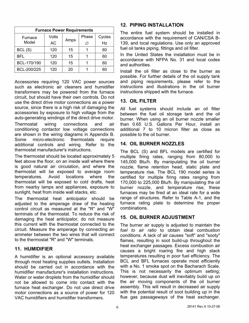
Furnace Power Requirements
Furnace Model
Volts AC
Amps Phase ∅
Cycles Hz
BCL (S) 120 15 1 60 BFL 120 15 1 60 BCL-170/190 120 15 1 60 BCL-200/225 120 20 1 60
Accessories requiring 120 VAC power sources such as electronic air cleaners and humidifier transformers may be powered from the furnace circuit, but should have their own controls. Do not use the direct drive motor connections as a power source, since there is a high risk of damaging the accessories by exposure to high voltage from the auto-generating windings of the direct drive motor. Thermostat wiring connections and air conditioning contactor low voltage connections are shown in the wiring diagrams in Appendix B. Some micro-electronic thermostats require additional controls and wiring. Refer to the thermostat manufacturer's instructions. The thermostat should be located approximately 5 feet above the floor, on an inside wall where there is good natural air circulation, and where the thermostat will be exposed to average room temperatures. Avoid locations where the thermostat will be exposed to cold drafts, heat from nearby lamps and appliances, exposure to sunlight, heat from inside wall stacks, etc. The thermostat heat anticipator should be adjusted to the amperage draw of the heating control circuit as measured at the "R" and "W" terminals of the thermostat. To reduce the risk of damaging the heat anticipator, do not measure this current with the thermostat connected to the circuit. Measure the amperage by connecting an ammeter between the two wires that will connect to the thermostat "R" and "W" terminals.
11. HUMIDIFIER A humidifier is an optional accessory available through most heating supplies outlets. Installation should be carried out in accordance with the humidifier manufacturer's installation instructions. Water or water droplets from the humidifier should not be allowed to come into contact with the furnace heat exchanger. Do not use direct drive motor connections as a source of power for 120 VAC humidifiers and humidifier transformers.
12. PIPING INSTALLATION The entire fuel system should be installed in accordance with the requirement of CAN/CSA B-139, and local regulations. Use only an approved fuel oil tanks piping, fittings and oil filter. In the United States the installation must be in accordance with NFPA No. 31 and local codes and authorities. Install the oil filter as close to the burner as possible. For further details of the oil supply tank and piping requirements, please refer to the instructions and illustrations in the oil burner instructions shipped with the furnace.
13. OIL FILTER All fuel systems should include an oil filter between the fuel oil storage tank and the oil burner. When using an oil burner nozzle smaller than 0.65 U.S. Gallons Per Hour, install an additional 7 to 10 micron filter as close as possible to the oil burner.
14. OIL BURNER NOZZLES The BCL (S) and BFL models are certified for multiple firing rates, ranging from 80,000 to 145,000 Btu/h. By manipulating the oil burner nozzle, flame retention head, static plate and temperature rise. The BCL 190 model series is certified for multiple firing rates ranging from 170,000 to 225,000 Btu/h. By manipulating the oil burner nozzle, and temperature rise, these furnaces may be fired at an ideal rate for a wide range of structures. Refer to Table A-1, and the furnace rating plate to determine the proper combinations.
15. OIL BURNER ADJUSTMENT The burner air supply is adjusted to maintain the fuel to air ratio to obtain ideal combustion conditions. A lack of air causes "soft" and "sooty" flames, resulting in soot build-up throughout the heat exchanger passages. Excess combustion air causes a bright roaring fire and high stack temperatures resulting in poor fuel efficiency. The BCL and BFL furnaces operate most efficiently with a No. 1 smoke spot on the Bacharach Scale. This is not necessarily the optimum setting; however, because dust will inevitably build up on the air moving components of the oil burner assembly. This will result in decreased air supply with the potential result of soot building up in the flue gas passageways of the heat exchanger.
28141 Rev A 10-27-06 7
Soot behaves as an insulator and impairs good heat transfer. Stack temperature will increase, and the overall efficiency will decrease. As a means of avoiding this problem, it is advisable to adjust the air supply to provide no more than a trace smoke spot on the Bacharach Scale.
NOTE: SIDEWALL VENTED MODELS SHOULD BE SET UP TO DELIVER ZERO (0) SMOKE.
BEFORE OPERATING THE FURNACE CHECK BURNER ALIGNMENT WITH COMBUSTION CHAMBER. THE END CONE OF THE AIR TUBE MUST BE CENTRED TO THE ACCOMODATING RING PROVIDED IN THE DESIGN OF THE COMBUSTION CHAMBER. ADJUST AS NECESSARY.
See the Venting Instructions included in the Vent Kits for set-up details for sidewall vented furnaces.
16. BURNER ELECTRODES Correct positioning of the electrode tips with respect to each other, to the fuel oil nozzle, and to the rest of the burner is essential for smooth light ups and proper operation. Refer to the oil burner instructions shipped with the furnace for electrode specifications. NOTE: Beckett AF Series Burner electrode specifications have been revised. They should be adjusted to be 5/16” above the nozzle centerline. Use of Beckett’s “Z” gauge is recommended
17. BURNER PRIMARY CONTROL The furnace is equipped with a primary combustion control, sometimes refer to as the burner relay or burner protector relay, which uses a light sensing device (cad cell) located in the burner housing, to monitor and control combustion. Over time, dust or combustion residuals can build up on the lens of the cad cell impairing its response to the flame. The cad cell should be checked for cleanliness and proper alignment if the primary control frequently shuts down combustion.
ALL FURNACE CONTROLS ARE SENSITIVE AND SHOULD NOT BE SUBJECTED TO TAMPERING. IF PROBLEMS PERSIST, CALL YOUR SERVICE CONTRACTOR.
18. COMBUSTION CHAMBER This furnace is equipped with a high quality cerafelt combustion chamber. It is held in place by a support bracket and stainless steel retaining band and clamp. CHECK THE ALIGNMENT OF THE COMBUSTION CHAMBER AND OIL BURNER BEFORE FIRING. IT IS POSSIBLE FOR THE COMBUSTION CHAMBER TO SHIFT IF SUBJECTED TO ROUGH HANDLING DURING TRANSIT. The combustion chamber should be inspected for damage or carbon build up whenever the oil burner is removed for repairs or routine maintenance.
DO NOT START THE BURNER UNLESS THE BLOWER ACCESS DOOR IS SECURED IN PLACE.
19. CIRCULATING AIR BLOWER The BCL and BFL furnaces are equipped with either direct drive or belt drive blower systems. Direct drive blower speed adjustments are not normally required in properly sized extended plenum duct systems. The motor RPM and air CFM delivery will vary automatically to accommodate conditions within the usual range of external static pressures typical of residential duct systems. Under-sized duct systems may require a higher blower speed to obtain a reasonable system temperature rise. Some older duct systems were not designed to provide static pressure. They typically feature special reducing fittings at each branch run and lack block ends on the trunk ducts. These systems may require modification to provide some resistance to the airflow to prevent over- amping of the direct drive blower motor. Selecting a lower blower speed
28141 Rev A 10-27-06 8
may correct this problem; however, a belt drive blower system is the better solution, since motor RPM and CFM delivery is not particularly influenced by system external static pressure. Direct drive blower speeds are adjusted by changing the "hot" wires to the motor winding connections. Please refer to wiring diagrams in Appendix B or the wiring diagram label affixed to the furnace. THE NEUTRAL WIRE (normally the white wire) IS NEVER MOVED TO ADJUST THE BLOWER SPEED. It is possible and acceptable to use a single blower speed for both heating and cooling modes. The simplest method to connect the wiring from both modes is to use a "piggy-back connector" accommodating both wires on a single motor tap. It is also acceptable to connect the selected motor speed with a pig tail joined to both heating and cooling speed wires with a wire nut. As a safety precaution against accidental disconnection of the wires by vibration, it is advisable to secure the wire nut and wires with a few wraps of electricians tape.
DO NOT CONNECT POWER LEADS BETWEEN MOTOR SPEEDS. THE NEUTRAL WIRE MUST ALWAYS BE CONNECTED TO THE MOTOR'S DESIGNATED NEUTRAL TERMINAL.
DISCONNECT THE POWER SUPPLY TO THE FURNACE BEFORE OPENING THE BLOWER ACCESS DOOR TO SERVICE THE AIR FILTER, FAN AND MOTOR. FAILURE TO SHUT OFF POWER COULD ALLOW THE BLOWER TO START UNEXPECTEDLY, CREATING A RISK OF DEATH OR PERSONAL INJURY.
If the joining of the blower speed wiring is done in the furnace junction box, tape off both ends of the unused wire.
Do not use the blower speed wires as a source of power to accessories as electronic air cleaners and humidifier transformers unless it is certain that only one motor speed will be used. The unused motor taps auto-generate sufficiently high voltages to damage accessory equipment. Belt drive blower systems can be modified for a variety of speeds and air delivery by adjusting the variable speed motor pulley, and by changing the blower pulley. The variable speed motor pulley may be adjusted by loosening the 5/32 Allen set screw in the outer sheave, and turning the outer sheave clockwise to increase blower speed; counter clockwise to reduce blower speed. Ensure that the setscrew is tightened at one of the "flat spots", failure to do so will convert the variable speed pulley to a fixed speed pulley by ruining the threads. The blower speed can be modified by the changing of the blower pulley. A smaller blower pulley will cause the blower to turn faster; a larger pulley will reduce blower speed. Large increases in blower speed may increase power requirements. Check the amperage draw of the blower motor after changes have been made. If the amperage draw is greater than the value listed on the motor rating plate, replace with a motor of higher horsepower. The fan belt tension is very important. There should be a deflection of ¾ of an inch to 1 inch. Less deflection places a strain on the blower bearings, and increases start up amperage draw. More deflection allows excess slippage and causes premature motor pulley wear. Automotive belt dressings are not recommended. A hard soap such as Sunlight® soap will work well as a belt dressing, for the purpose of reducing belt squeaks, etc. If used, the soap should be applied to the sides of the belt only.
THE BELT DRIVE COMPONENTS OPERATE AT HIGH SPEEDS AND CAN EASILY SNAG LOOSE CLOTHING, CAUSING SERIOUS PERSONAL INJURY. THIS PROCEDURE SHOULD BE LEFT TO TRAINED SERVICE PERSONNEL.
If planning to operate the belt drive blower at speeds above 1100 RPM, it is advisable to
28141 Rev A 10-27-06 9
replace the cintered bronze blower bearings with roller Bearings. The blower assembly used in the BCL 200 / 225 model is equipped with roller Bearings.
DO NOT CONNECT POWER LEADS BETWEEN MOTOR SPEEDS. THE NEUTRAL WIRE MUST ALWAYS BE CONNECTED TO THE MOTOR'S DESIGNATED NEUTRAL TERMINAL.
20. MAINTENANCE AND SERVICE A: Routine Maintenance By Home Owner Other than remembering to arrange for the annual professional servicing of the furnace by the service or installation contractor, the most important routine service performed by the homeowner is to maintain the air filter or filters. A dirty filter can cause the furnace to over-heat, fail to maintain indoor temperature during cold weather, increase fuel consumption and cause component failure. The furnace filter(s) should be inspected, cleaned or replaced monthly. The furnace is factory equipped with a semi-permanent type filter. If the filter is damaged, replace with filters of the same size and type. (See Appendix A, Table A-11). During the routine service, inspect the general condition of the furnace watching for signs of oil leaks in the vicinity of the oil burner, soot forming on any external part of the furnace, soot forming around the joints in the vent pipe, etc. If any of these conditions are present, please advice your service or installation contractor. Annual Service By Contractor
THE COMBUSTION CHAMBER (FIREPOT) IS FRAGILE. USE CARE WHEN INSPECTING AND CLEANING THIS AREA.
The heat exchanger, and flue pipe on rear breach units, should be inspected periodically and cleaned if necessary. if cleaning is necessary, SHUT OFF POWER TO THE FURNACE and remove the burner. Using a stiff brush with a wire handle, brush off scale and
soot from inside the drum and flue pipe. The Flue Connector shall be removed to inspect and clean the flue pipe area. To clean the radiator, remove the round covers on the inner front panel to gain access to the cleaning ports. When this procedure is done for the first time, carefully cut away the insulation covering the opening with a sharp knife. Loosen the nuts on the radiator clean-outs. DO NOT REMOVE THE NUTS. Remove the covers carefully to avoid tearing the gaskets. A wire brush can be used to loosen dirt and debris on the inside surfaces of the radiator. Clean out all accumulated dirt, soot and debris with a wire handled brush and industrial a vacuum cleaner. Before replacing the clean-out covers, inspect the gaskets. If the gaskets are broken, remove the remnants and replace with new gaskets. Snug the cleanout covers. DO NOT OVER-TORQUE THE CLEAN-OUT NUTS. Replace the inner front panel clean-out covers. NOTE: A radiator clean-out assembly inadvertently dropped into the interior of the furnace can usually be easily retrieved with a magnet on a wire handle or stout string. The direct drive blower motor is factory oiled. Under normal operating conditions it does not require oiling for the first two years. Oil sparingly (a few drops) with SAE 20 non-detergent oil. Oiling is most easily done with a "tele-spout" oiler. This oiler has a long flexible plastic spout. DO NOT OVER-LUBRICATE. Excess oil causes premature electric motor failure. Belt drive blower motors require the same oiling program. Inspect the blower fan. Clean if necessary.
Oil Burner Maintenance: Follow the instructions of the oil burner manufacturer. (See oil burner manufacturer's instructions supplied with furnace). It is advisable to change the oil burner nozzle and oil filter on an annual basis. The venting system should be cleaned and inspected for signs of deterioration. Replace pitted or perforated vent pipe and fittings. The barometric damper should open and close freely. All electrical connections should be checked to ensure tight connections. Safety controls such as the high limit controls should be tested for functionality. The fan control should be checked to ensure that the "fan off" function continues to stop the blower fan at temperatures between 90°F to 100°F.
28141 Rev A 10-27-06 10
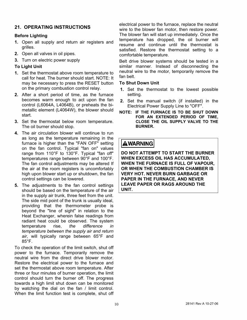
21. OPERATING INSTRUCTIONS Before Lighting 1. Open all supply and return air registers and
grilles. 2. Open all valves in oil pipes. 3. Turn on electric power supply To Light Unit 1. Set the thermostat above room temperature to
call for heat. The burner should start. NOTE: It may be necessary to press the RESET button on the primary combustion control relay.
2. After a short period of time, as the furnace becomes warm enough to act upon the fan control (L6064A, L4064B), or preheats the bi-metallic element (L4064W), the blower should start.
3. Set the thermostat below room temperature. The oil burner should stop.
4. The air circulation blower will continue to run as long as the temperature remaining in the furnace is higher than the "FAN OFF" setting on the fan control. Typical "fan on" values range from 110°F to 130°F. Typical "fan off" temperatures range between 90°F and 100°F. The fan control adjustments may be altered If the air at the room registers is uncomfortably high upon blower start up or shutdown, the fan control settings can be lowered.
5. The adjustments to the fan control settings should be based on the temperature of the air in the supply air trunk, three feet from the unit. The side mid point of the trunk is usually ideal, providing that the thermometer probe is beyond the "line of sight" in relation to the Heat Exchanger, wherein false readings from radiant heat could be observed. The system temperature rise, the difference in temperature between the supply air and return air, will typically range between 65°F and 85°F.
To check the operation of the limit switch, shut off power to the furnace. Temporarily remove the neutral wire from the direct drive blower motor. Restore the electrical power to the furnace and set the thermostat above room temperature. After three or four minutes of burner operation, the limit control should turn the burner off. The progress towards a high limit shut down can be monitored by watching the dial on the fan / limit control. When the limit function test is complete, shut off
electrical power to the furnace, replace the neutral wire to the blower fan motor, then restore power. The blower fan will start up immediately. Once the temperature has dropped, the oil burner will resume and continue until the thermostat is satisfied. Restore the thermostat setting to a comfortable temperature. Belt drive blower systems should be tested in a similar manner. Instead of disconnecting the neutral wire to the motor, temporarily remove the fan belt. To Shut Down Unit 1. Set the thermostat to the lowest possible
setting. 2. Set the manual switch (if installed) in the
Electrical Power Supply Line to "OFF". NOTE: IF THE FURNACE IS TO BE SHUT DOWN
FOR AN EXTENDED PERIOD OF TIME, CLOSE THE OIL SUPPLY VALVE TO THE BURNER.
DO NOT ATTEMPT TO START THE BURNER WHEN EXCESS OIL HAS ACCUMULATED, WHEN THE FURNACE IS FULL OF VAPOUR, OR WHEN THE COMBUSTION CHAMBER IS VERY HOT. NEVER BURN GARBAGE OR PAPER IN THE FURNACE, AND NEVER LEAVE PAPER OR RAGS AROUND THE UNIT.
28141 Rev A 10-27-06 11
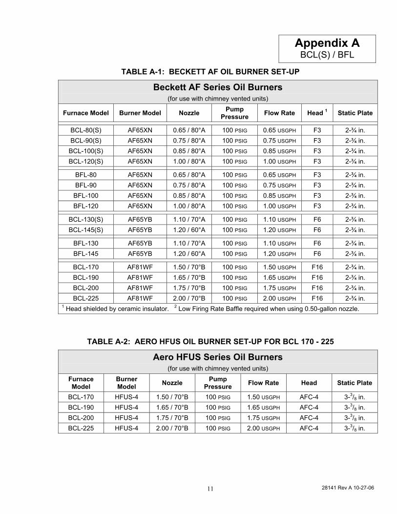
TABLE A-1: BECKETT AF OIL BURNER SET-UP
Beckett AF Series Oil Burners (for use with chimney vented units)
Furnace Model Burner Model Nozzle Pump Pressure Flow Rate Head 1 Static Plate
BCL-80(S) AF65XN 0.65 / 80°A 100 PSIG 0.65 USGPH F3 2-¾ in. BCL-90(S) AF65XN 0.75 / 80°A 100 PSIG 0.75 USGPH F3 2-¾ in.
BCL-100(S) AF65XN 0.85 / 80°A 100 PSIG 0.85 USGPH F3 2-¾ in. BCL-120(S) AF65XN 1.00 / 80°A 100 PSIG 1.00 USGPH F3 2-¾ in.
BFL-80 AF65XN 0.65 / 80°A 100 PSIG 0.65 USGPH F3 2-¾ in. BFL-90 AF65XN 0.75 / 80°A 100 PSIG 0.75 USGPH F3 2-¾ in.
BFL-100 AF65XN 0.85 / 80°A 100 PSIG 0.85 USGPH F3 2-¾ in. BFL-120 AF65XN 1.00 / 80°A 100 PSIG 1.00 USGPH F3 2-¾ in.
BCL-130(S) AF65YB 1.10 / 70°A 100 PSIG 1.10 USGPH F6 2-¾ in. BCL-145(S) AF65YB 1.20 / 60°A 100 PSIG 1.20 USGPH F6 2-¾ in.
BFL-130 AF65YB 1.10 / 70°A 100 PSIG 1.10 USGPH F6 2-¾ in. BFL-145 AF65YB 1.20 / 60°A 100 PSIG 1.20 USGPH F6 2-¾ in.
BCL-170 AF81WF 1.50 / 70°B 100 PSIG 1.50 USGPH F16 2-¾ in. BCL-190 AF81WF 1.65 / 70°B 100 PSIG 1.65 USGPH F16 2-¾ in. BCL-200 AF81WF 1.75 / 70°B 100 PSIG 1.75 USGPH F16 2-¾ in. BCL-225 AF81WF 2.00 / 70°B 100 PSIG 2.00 USGPH F16 2-¾ in.
1 Head shielded by ceramic insulator. 2 Low Firing Rate Baffle required when using 0.50-gallon nozzle.
TABLE A-2: AERO HFUS OIL BURNER SET-UP FOR BCL 170 - 225
Aero HFUS Series Oil Burners (for use with chimney vented units)
Furnace Model
Burner Model Nozzle Pump
Pressure Flow Rate Head Static Plate
BCL-170 HFUS-4 1.50 / 70°B 100 PSIG 1.50 USGPH AFC-4 3-3/8 in. BCL-190 HFUS-4 1.65 / 70°B 100 PSIG 1.65 USGPH AFC-4 3-3/8 in. BCL-200 HFUS-4 1.75 / 70°B 100 PSIG 1.75 USGPH AFC-4 3-3/8 in. BCL-225 HFUS-4 2.00 / 70°B 100 PSIG 2.00 USGPH AFC-4 3-3/8 in.
Appendix A BCL(S) / BFL
28141 Rev A 10-27-06 12
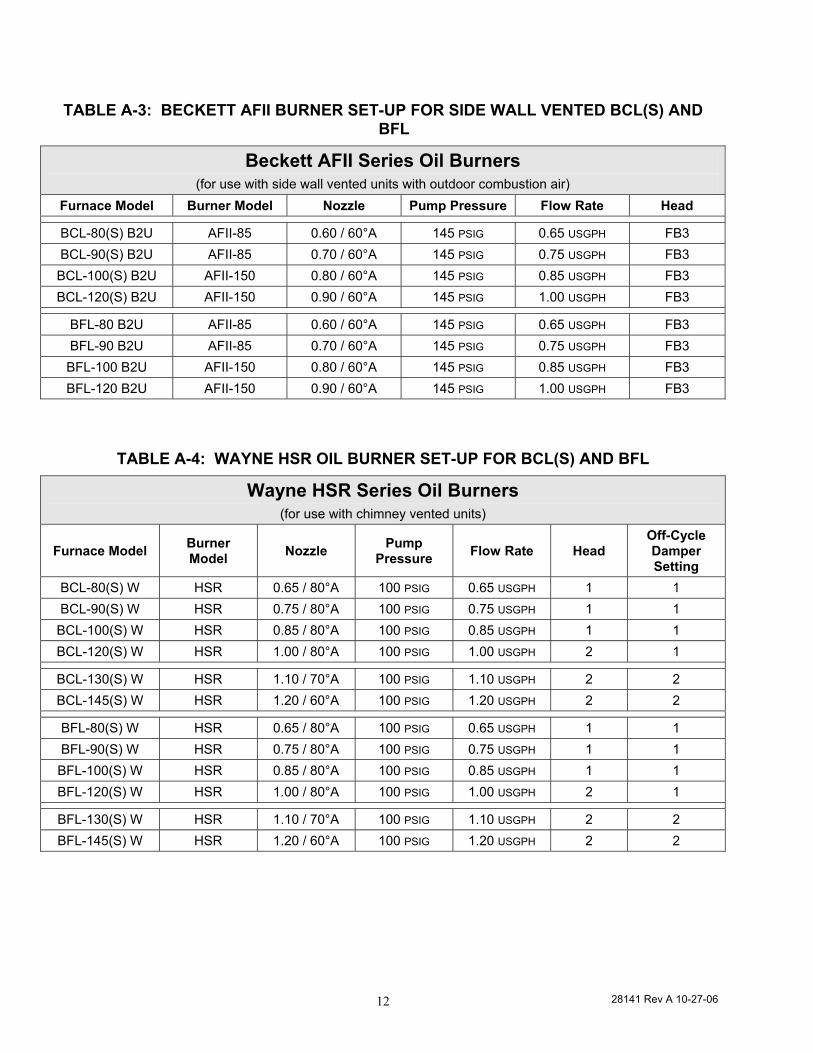
TABLE A-3: BECKETT AFII BURNER SET-UP FOR SIDE WALL VENTED BCL(S) AND BFL
Beckett AFII Series Oil Burners (for use with side wall vented units with outdoor combustion air)
Furnace Model Burner Model Nozzle Pump Pressure Flow Rate Head
BCL-80(S) B2U AFII-85 0.60 / 60°A 145 PSIG 0.65 USGPH FB3 BCL-90(S) B2U AFII-85 0.70 / 60°A 145 PSIG 0.75 USGPH FB3 BCL-100(S) B2U AFII-150 0.80 / 60°A 145 PSIG 0.85 USGPH FB3 BCL-120(S) B2U AFII-150 0.90 / 60°A 145 PSIG 1.00 USGPH FB3
BFL-80 B2U AFII-85 0.60 / 60°A 145 PSIG 0.65 USGPH FB3 BFL-90 B2U AFII-85 0.70 / 60°A 145 PSIG 0.75 USGPH FB3 BFL-100 B2U AFII-150 0.80 / 60°A 145 PSIG 0.85 USGPH FB3 BFL-120 B2U AFII-150 0.90 / 60°A 145 PSIG 1.00 USGPH FB3
TABLE A-4: WAYNE HSR OIL BURNER SET-UP FOR BCL(S) AND BFL
Wayne HSR Series Oil Burners (for use with chimney vented units)
Furnace Model Burner Model Nozzle Pump
Pressure Flow Rate Head Off-Cycle Damper Setting
BCL-80(S) W HSR 0.65 / 80°A 100 PSIG 0.65 USGPH 1 1 BCL-90(S) W HSR 0.75 / 80°A 100 PSIG 0.75 USGPH 1 1
BCL-100(S) W HSR 0.85 / 80°A 100 PSIG 0.85 USGPH 1 1 BCL-120(S) W HSR 1.00 / 80°A 100 PSIG 1.00 USGPH 2 1
BCL-130(S) W HSR 1.10 / 70°A 100 PSIG 1.10 USGPH 2 2 BCL-145(S) W HSR 1.20 / 60°A 100 PSIG 1.20 USGPH 2 2
BFL-80(S) W HSR 0.65 / 80°A 100 PSIG 0.65 USGPH 1 1 BFL-90(S) W HSR 0.75 / 80°A 100 PSIG 0.75 USGPH 1 1 BFL-100(S) W HSR 0.85 / 80°A 100 PSIG 0.85 USGPH 1 1 BFL-120(S) W HSR 1.00 / 80°A 100 PSIG 1.00 USGPH 2 1
BFL-130(S) W HSR 1.10 / 70°A 100 PSIG 1.10 USGPH 2 2 BFL-145(S) W HSR 1.20 / 60°A 100 PSIG 1.20 USGPH 2 2
28141 Rev A 10-27-06 13
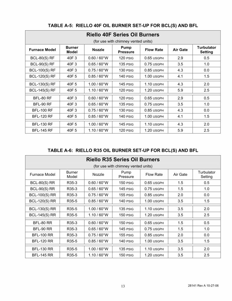
TABLE A-5: RIELLO 40F OIL BURNER SET-UP FOR BCL(S) AND BFL
Riello 40F Series Oil Burners (for use with chimney vented units)
Furnace Model Burner Model Nozzle Pump
Pressure Flow Rate Air Gate Turbulator Setting
BCL-80(S) RF 40F 3 0.60 / 60°W 120 PSIG 0.65 USGPH 2.9 0.5 BCL-90(S) RF 40F 3 0.65 / 60°W 135 PSIG 0.75 USGPH 3.5 1.0 BCL-100(S) RF 40F 3 0.75 / 60°W 130 PSIG 0.85 USGPH 4.3 0.0 BCL-120(S) RF 40F 5 0.85 / 60°W 140 PSIG 1.00 USGPH 4.1 1.5
BCL-130(S) RF 40F 5 1.00 / 60°W 145 PSIG 1.10 USGPH 4.3 2.0 BCL-145(S) RF 40F 5 1.10 / 60°W 120 PSIG 1.20 USGPH 5.9 2.5
BFL-80 RF 40F 3 0.60 / 60°W 120 PSIG 0.65 USGPH 2.9 0.5 BFL-90 RF 40F 3 0.65 / 60°W 135 PSIG 0.75 USGPH 3.5 1.0 BFL-100 RF 40F 3 0.75 / 60°W 130 PSIG 0.85 USGPH 4.3 0.0 BFL-120 RF 40F 5 0.85 / 60°W 140 PSIG 1.00 USGPH 4.1 1.5
BFL-130 RF 40F 5 1.00 / 60°W 145 PSIG 1.10 USGPH 4.3 2.0 BFL-145 RF 40F 5 1.10 / 60°W 120 PSIG 1.20 USGPH 5.9 2.5
TABLE A-6: RIELLO R35 OIL BURNER SET-UP FOR BCL(S) AND BFL
Riello R35 Series Oil Burners (for use with chimney vented units)
Furnace Model Burner Model Nozzle Pump
Pressure Flow Rate Air Gate Turbulator Setting
BCL-80(S) RR R35-3 0.60 / 60°W 150 PSIG 0.65 USGPH 1.5 0.5 BCL-90(S) RR R35-3 0.65 / 60°W 145 PSIG 0.75 USGPH 1.5 1.0
BCL-100(S) RR R35-3 0.75 / 60°W 155 PSIG 0.85 USGPH 2.0 0.0 BCL-120(S) RR R35-5 0.85 / 60°W 140 PSIG 1.00 USGPH 3.5 1.5
BCL-130(S) RR R35-5 1.00 / 60°W 135 PSIG 1.10 USGPH 3.5 2.0 BCL-145(S) RR R35-5 1.10 / 60°W 150 PSIG 1.20 USGPH 3.5 2.5
BFL-80 RR R35-3 0.60 / 60°W 150 PSIG 0.65 USGPH 1.5 0.5 BFL-90 RR R35-3 0.65 / 60°W 145 PSIG 0.75 USGPH 1.5 1.0
BFL-100 RR R35-3 0.75 / 60°W 155 PSIG 0.85 USGPH 2.0 0.0 BFL-120 RR R35-5 0.85 / 60°W 140 PSIG 1.00 USGPH 3.5 1.5
BFL-130 RR R35-5 1.00 / 60°W 135 PSIG 1.10 USGPH 3.5 2.0 BFL-145 RR R35-5 1.10 / 60°W 150 PSIG 1.20 USGPH 3.5 2.5
28141 Rev A 10-27-06 14
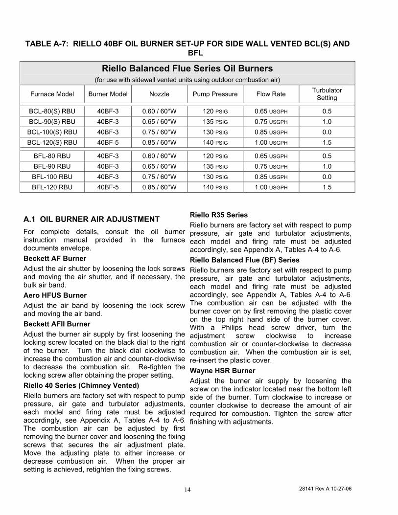
TABLE A-7: RIELLO 40BF OIL BURNER SET-UP FOR SIDE WALL VENTED BCL(S) AND BFL
Riello Balanced Flue Series Oil Burners (for use with sidewall vented units using outdoor combustion air)
Furnace Model Burner Model Nozzle Pump Pressure Flow Rate Turbulator Setting
BCL-80(S) RBU 40BF-3 0.60 / 60°W 120 PSIG 0.65 USGPH 0.5 BCL-90(S) RBU 40BF-3 0.65 / 60°W 135 PSIG 0.75 USGPH 1.0 BCL-100(S) RBU 40BF-3 0.75 / 60°W 130 PSIG 0.85 USGPH 0.0 BCL-120(S) RBU 40BF-5 0.85 / 60°W 140 PSIG 1.00 USGPH 1.5
BFL-80 RBU 40BF-3 0.60 / 60°W 120 PSIG 0.65 USGPH 0.5 BFL-90 RBU 40BF-3 0.65 / 60°W 135 PSIG 0.75 USGPH 1.0 BFL-100 RBU 40BF-3 0.75 / 60°W 130 PSIG 0.85 USGPH 0.0 BFL-120 RBU 40BF-5 0.85 / 60°W 140 PSIG 1.00 USGPH 1.5
A.1 OIL BURNER AIR ADJUSTMENT For complete details, consult the oil burner instruction manual provided in the furnace documents envelope. Beckett AF Burner Adjust the air shutter by loosening the lock screws and moving the air shutter, and if necessary, the bulk air band. Aero HFUS Burner Adjust the air band by loosening the lock screw and moving the air band. Beckett AFII Burner Adjust the burner air supply by first loosening the locking screw located on the black dial to the right of the burner. Turn the black dial clockwise to increase the combustion air and counter-clockwise to decrease the combustion air. Re-tighten the locking screw after obtaining the proper setting. Riello 40 Series (Chimney Vented) Riello burners are factory set with respect to pump pressure, air gate and turbulator adjustments, each model and firing rate must be adjusted accordingly, see Appendix A, Tables A-4 to A-6. The combustion air can be adjusted by first removing the burner cover and loosening the fixing screws that secures the air adjustment plate. Move the adjusting plate to either increase or decrease combustion air. When the proper air setting is achieved, retighten the fixing screws.
Riello R35 Series Riello burners are factory set with respect to pump pressure, air gate and turbulator adjustments, each model and firing rate must be adjusted accordingly, see Appendix A, Tables A-4 to A-6. Riello Balanced Flue (BF) Series Riello burners are factory set with respect to pump pressure, air gate and turbulator adjustments, each model and firing rate must be adjusted accordingly, see Appendix A, Tables A-4 to A-6.
The combustion air can be adjusted with the burner cover on by first removing the plastic cover on the top right hand side of the burner cover. With a Philips head screw driver, turn the adjustment screw clockwise to increase combustion air or counter-clockwise to decrease combustion air. When the combustion air is set, re-insert the plastic cover. Wayne HSR Burner Adjust the burner air supply by loosening the screw on the indicator located near the bottom left side of the burner. Turn clockwise to increase or counter clockwise to decrease the amount of air required for combustion. Tighten the screw after finishing with adjustments.
28141 Rev A 10-27-06 15
A.2 BURNER ELECTRODES Adjustment of the electrode tips with respect to each other, the nozzle, and to the rest of the burner is very important to ensure smooth start ups and to permit efficient combustion. Refer to the Burner Manufacturers Instructions for details.
A.3 START UP The furnace should be operated for a minimum of 15 minutes to reach steady state conditions before fine tuning combustion. The warm up time is ideal for testing the oil pump pressure. Drill a 1/4 inch test port in the venting between the furnace flue outlet and draft regulator (barometric damper). Insert a stack thermometer and note the flue gas temperature. The flue gases should be within a range of 350°F to 575°F. If the flue gases are below the range, it may be necessary to slow down the blower fan. If the flue gases are above the range, the blower fan may require speeding up. Stack temperature varies directly with the system temperature rise. System temperature rise is the difference between the furnace outlet temperature and furnace inlet temperature as measured in the vicinity of the connection between the plenum take-offs and the trunk ducts. Typical temperature rise values range between 65°F and 85°F.
Perform a smoke spot test. The smoke spot should not exceed No. 1 on the Bacharach Scale. After the air adjustments have been completed, re-check the draft pressure at the same point as the smoke spot test. The over fire draft should be adjusted to 0.02 inches w.c. In the United States, the Beckett AF Burner may be equipped with Beckett's "Inlet Air Shut-Off" to increase efficiency. (Beckett Part No. AF/A 5861).
NOTE: USE OF THE INLET AIR SHUT-OFF COULD CAUSE POST COMBUSTION NOZZLE DRIP.
A.4 SPECIAL INSTRUCTIONS FOR UNITS EQUIPPED WITH RIELLO BURNERS
Riello burners are factory set with respect to pump pressure, air gate and turbulator adjustments, each model and firing rate must be adjusted accordingly, see Appendix A, Tables A-4 to A-6.
Consult the Riello Installation Instructions supplied with the furnace documents envelope for specific information concerning burner adjustments, operation, and trouble-shooting.
28141 Rev A 10-27-06 16
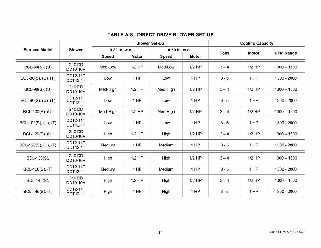
TABLE A-8: DIRECT DRIVE BLOWER SET-UP Blower Set-Up Cooling Capacity
0.20 in. w.c. 0.50 in. w.c. Furnace Model Blower Speed Motor Speed Motor
Tons Motor CFM Range
BCL-80(S), (U) G10 DD DD10-10A Med-Low 1/2 HP Med-Low 1/2 HP 3 – 4 1/2 HP 1000 – 1600
BCL-80(S), (U), (T) DD12-11T DCT12-11 Low 1 HP Low 1 HP 3 - 5 1 HP 1300 - 2000
BCL-90(S), (U) G10 DD DD10-10A Med-High 1/2 HP Med-High 1/2 HP 3 – 4 1/2 HP 1000 – 1600
BCL-90(S), (U), (T) DD12-11T DCT12-11 Low 1 HP Low 1 HP 3 - 5 1 HP 1300 - 2000
BCL-100(S), (U) G10 DD DD10-10A Med-High 1/2 HP Med-High 1/2 HP 3 – 4 1/2 HP 1000 – 1600
BCL-100(S), (U), (T) DD12-11T DCT12-11 Low 1 HP Low 1 HP 3 - 5 1 HP 1300 - 2000
BCL-120(S), (U) G10 DD DD10-10A High 1/2 HP High 1/2 HP 3 – 4 1/2 HP 1000 – 1600
BCL-120(S), (U), (T) DD12-11T DCT12-11 Medium 1 HP Medium 1 HP 3 - 5 1 HP 1300 - 2000
BCL-130(S), G10 DD DD10-10A High 1/2 HP High 1/2 HP 3 – 4 1/2 HP 1000 – 1600
BCL-130(S), (T) DD12-11T DCT12-11 Medium 1 HP Medium 1 HP 3 - 5 1 HP 1300 - 2000
BCL-145(S), G10 DD DD10-10A High 1/2 HP High 1/2 HP 3 – 4 1/2 HP 1000 – 1600
BCL-145(S), (T) DD12-11T DCT12-11 High 1 HP High 1 HP 3 - 5 1 HP 1300 - 2000
28141 Rev A 10-27-06 17
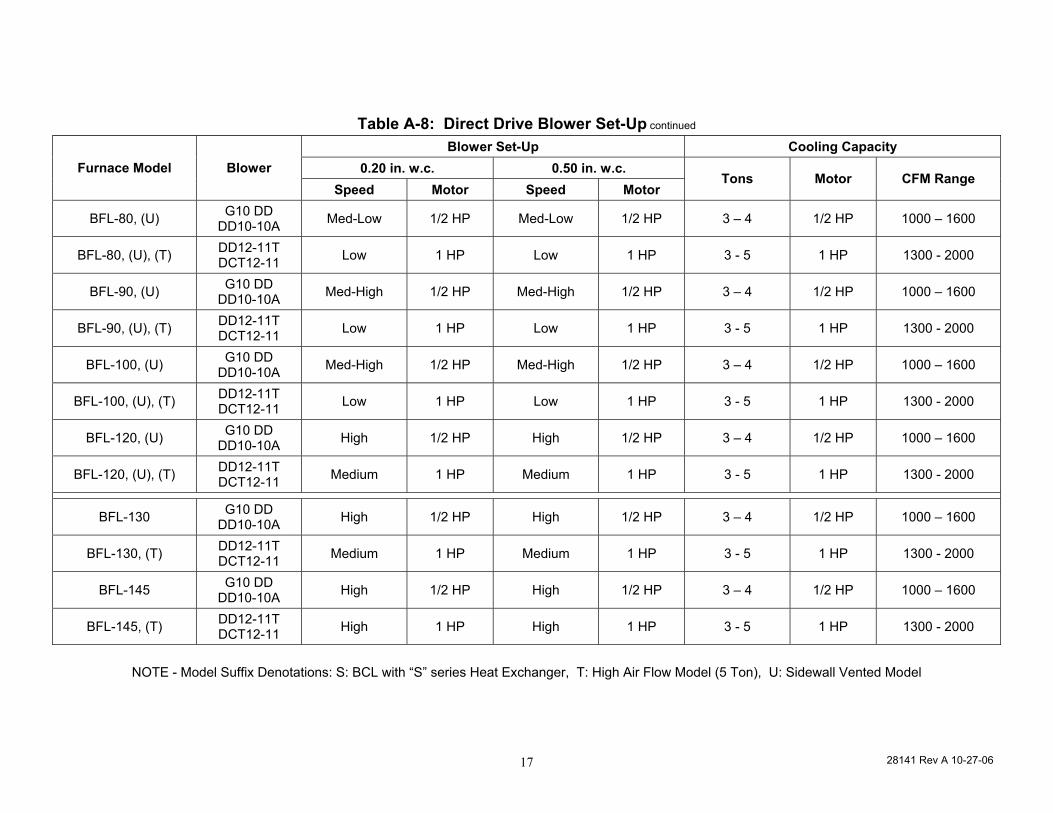
Table A-8: Direct Drive Blower Set-Up continued
Blower Set-Up Cooling Capacity 0.20 in. w.c. 0.50 in. w.c. Furnace Model Blower
Speed Motor Speed Motor Tons Motor CFM Range
BFL-80, (U) G10 DD DD10-10A Med-Low 1/2 HP Med-Low 1/2 HP 3 – 4 1/2 HP 1000 – 1600
BFL-80, (U), (T) DD12-11T DCT12-11 Low 1 HP Low 1 HP 3 - 5 1 HP 1300 - 2000
BFL-90, (U) G10 DD DD10-10A Med-High 1/2 HP Med-High 1/2 HP 3 – 4 1/2 HP 1000 – 1600
BFL-90, (U), (T) DD12-11T DCT12-11 Low 1 HP Low 1 HP 3 - 5 1 HP 1300 - 2000
BFL-100, (U) G10 DD DD10-10A Med-High 1/2 HP Med-High 1/2 HP 3 – 4 1/2 HP 1000 – 1600
BFL-100, (U), (T) DD12-11T DCT12-11 Low 1 HP Low 1 HP 3 - 5 1 HP 1300 - 2000
BFL-120, (U) G10 DD DD10-10A High 1/2 HP High 1/2 HP 3 – 4 1/2 HP 1000 – 1600
BFL-120, (U), (T) DD12-11T DCT12-11 Medium 1 HP Medium 1 HP 3 - 5 1 HP 1300 - 2000
BFL-130 G10 DD DD10-10A High 1/2 HP High 1/2 HP 3 – 4 1/2 HP 1000 – 1600
BFL-130, (T) DD12-11T DCT12-11 Medium 1 HP Medium 1 HP 3 - 5 1 HP 1300 - 2000
BFL-145 G10 DD DD10-10A High 1/2 HP High 1/2 HP 3 – 4 1/2 HP 1000 – 1600
BFL-145, (T) DD12-11T DCT12-11 High 1 HP High 1 HP 3 - 5 1 HP 1300 - 2000
NOTE - Model Suffix Denotations: S: BCL with “S” series Heat Exchanger, T: High Air Flow Model (5 Ton), U: Sidewall Vented Model
28141 Rev A 10-27-06 18
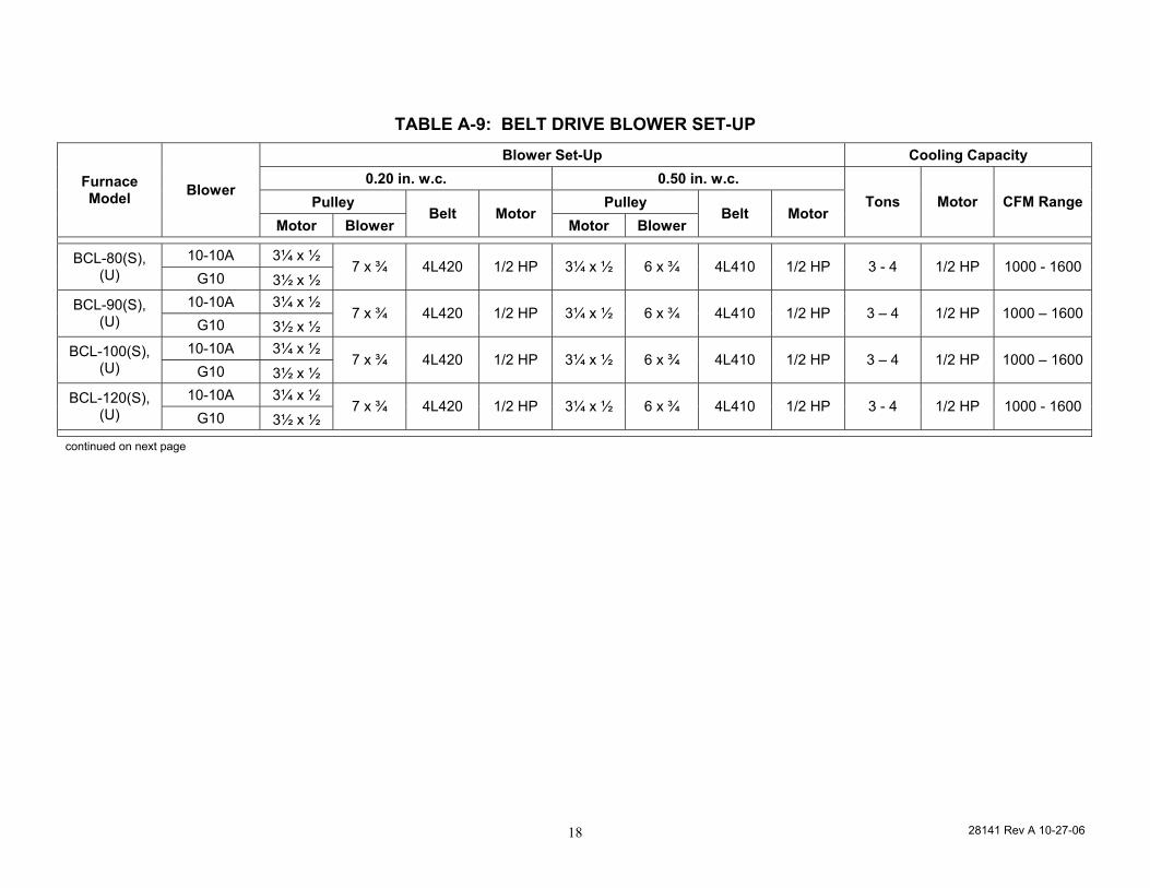
TABLE A-9: BELT DRIVE BLOWER SET-UP Blower Set-Up Cooling Capacity
0.20 in. w.c. 0.50 in. w.c. Pulley Pulley
Furnace Model Blower
Motor Blower Belt Motor
Motor Blower Belt Motor
Tons Motor CFM Range
10-10A 3¼ x ½ BCL-80(S), (U) G10 3½ x ½
7 x ¾ 4L420 1/2 HP 3¼ x ½ 6 x ¾ 4L410 1/2 HP 3 - 4 1/2 HP 1000 - 1600
10-10A 3¼ x ½ BCL-90(S), (U) G10 3½ x ½
7 x ¾ 4L420 1/2 HP 3¼ x ½ 6 x ¾ 4L410 1/2 HP 3 – 4 1/2 HP 1000 – 1600
10-10A 3¼ x ½ BCL-100(S), (U) G10 3½ x ½
7 x ¾ 4L420 1/2 HP 3¼ x ½ 6 x ¾ 4L410 1/2 HP 3 – 4 1/2 HP 1000 – 1600
10-10A 3¼ x ½ BCL-120(S), (U) G10 3½ x ½
7 x ¾ 4L420 1/2 HP 3¼ x ½ 6 x ¾ 4L410 1/2 HP 3 - 4 1/2 HP 1000 - 1600
continued on next page
28141 Rev A 10-27-06 19
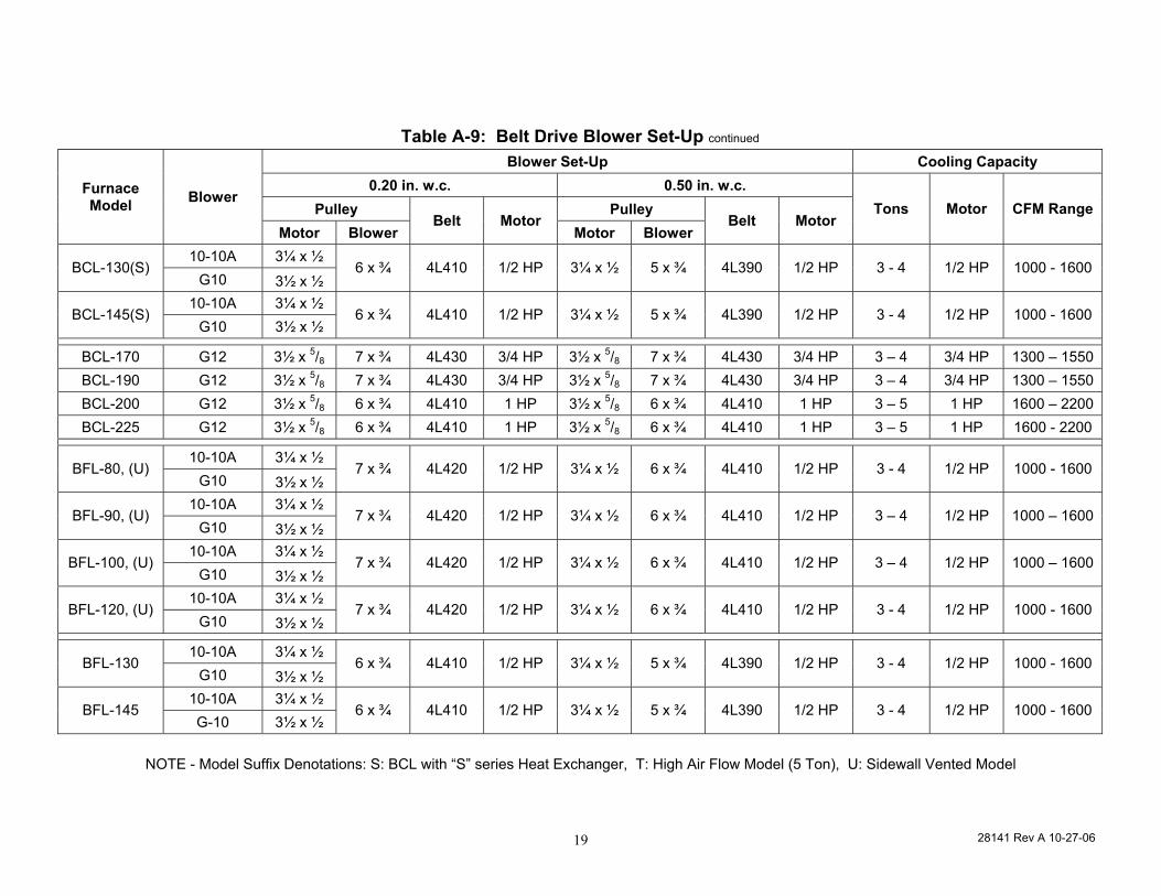
Table A-9: Belt Drive Blower Set-Up continued
Blower Set-Up Cooling Capacity 0.20 in. w.c. 0.50 in. w.c.
Pulley Pulley Furnace Model Blower
Motor Blower Belt Motor
Motor Blower Belt Motor
Tons Motor CFM Range
10-10A 3¼ x ½ BCL-130(S)
G10 3½ x ½ 6 x ¾ 4L410 1/2 HP 3¼ x ½ 5 x ¾ 4L390 1/2 HP 3 - 4 1/2 HP 1000 - 1600
10-10A 3¼ x ½ BCL-145(S)
G10 3½ x ½ 6 x ¾ 4L410 1/2 HP 3¼ x ½ 5 x ¾ 4L390 1/2 HP 3 - 4 1/2 HP 1000 - 1600
BCL-170 G12 3½ x 5/8 7 x ¾ 4L430 3/4 HP 3½ x 5/8 7 x ¾ 4L430 3/4 HP 3 – 4 3/4 HP 1300 – 1550 BCL-190 G12 3½ x 5/8 7 x ¾ 4L430 3/4 HP 3½ x 5/8 7 x ¾ 4L430 3/4 HP 3 – 4 3/4 HP 1300 – 1550 BCL-200 G12 3½ x 5/8 6 x ¾ 4L410 1 HP 3½ x 5/8 6 x ¾ 4L410 1 HP 3 – 5 1 HP 1600 – 2200 BCL-225 G12 3½ x 5/8 6 x ¾ 4L410 1 HP 3½ x 5/8 6 x ¾ 4L410 1 HP 3 – 5 1 HP 1600 - 2200
10-10A 3¼ x ½ BFL-80, (U)
G10 3½ x ½ 7 x ¾ 4L420 1/2 HP 3¼ x ½ 6 x ¾ 4L410 1/2 HP 3 - 4 1/2 HP 1000 - 1600
10-10A 3¼ x ½ BFL-90, (U)
G10 3½ x ½ 7 x ¾ 4L420 1/2 HP 3¼ x ½ 6 x ¾ 4L410 1/2 HP 3 – 4 1/2 HP 1000 – 1600
10-10A 3¼ x ½ BFL-100, (U)
G10 3½ x ½ 7 x ¾ 4L420 1/2 HP 3¼ x ½ 6 x ¾ 4L410 1/2 HP 3 – 4 1/2 HP 1000 – 1600
10-10A 3¼ x ½ BFL-120, (U)
G10 3½ x ½ 7 x ¾ 4L420 1/2 HP 3¼ x ½ 6 x ¾ 4L410 1/2 HP 3 - 4 1/2 HP 1000 - 1600
10-10A 3¼ x ½ BFL-130
G10 3½ x ½ 6 x ¾ 4L410 1/2 HP 3¼ x ½ 5 x ¾ 4L390 1/2 HP 3 - 4 1/2 HP 1000 - 1600
10-10A 3¼ x ½ BFL-145
G-10 3½ x ½ 6 x ¾ 4L410 1/2 HP 3¼ x ½ 5 x ¾ 4L390 1/2 HP 3 - 4 1/2 HP 1000 - 1600
NOTE - Model Suffix Denotations: S: BCL with “S” series Heat Exchanger, T: High Air Flow Model (5 Ton), U: Sidewall Vented Model
28141 Rev A 10-27-06 20
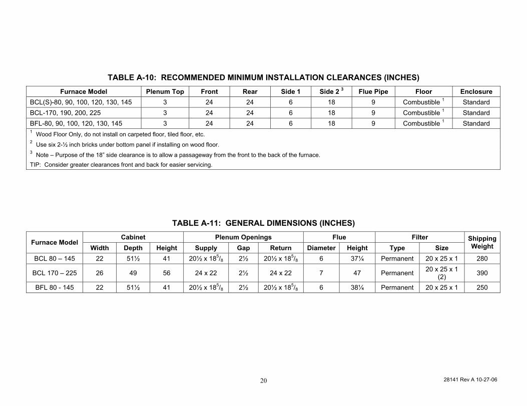
TABLE A-10: RECOMMENDED MINIMUM INSTALLATION CLEARANCES (INCHES) Furnace Model Plenum Top Front Rear Side 1 Side 2 3 Flue Pipe Floor Enclosure
BCL(S)-80, 90, 100, 120, 130, 145 3 24 24 6 18 9 Combustible 1 Standard BCL-170, 190, 200, 225 3 24 24 6 18 9 Combustible 1 Standard BFL-80, 90, 100, 120, 130, 145 3 24 24 6 18 9 Combustible 1 Standard 1 Wood Floor Only, do not install on carpeted floor, tiled floor, etc. 2 Use six 2-½ inch bricks under bottom panel if installing on wood floor. 3 Note – Purpose of the 18” side clearance is to allow a passageway from the front to the back of the furnace. TIP: Consider greater clearances front and back for easier servicing.
TABLE A-11: GENERAL DIMENSIONS (INCHES) Cabinet Plenum Openings Flue Filter
Furnace Model Width Depth Height Supply Gap Return Diameter Height Type Size
Shipping Weight
BCL 80 – 145 22 51½ 41 20½ x 185/8 2½ 20½ x 185/8 6 37¼ Permanent 20 x 25 x 1 280
BCL 170 – 225 26 49 56 24 x 22 2½ 24 x 22 7 47 Permanent 20 x 25 x 1 (2) 390
BFL 80 - 145 22 51½ 41 20½ x 185/8 2½ 20½ x 185/8 6 38¼ Permanent 20 x 25 x 1 250
28141 Rev A 10-27-06 21
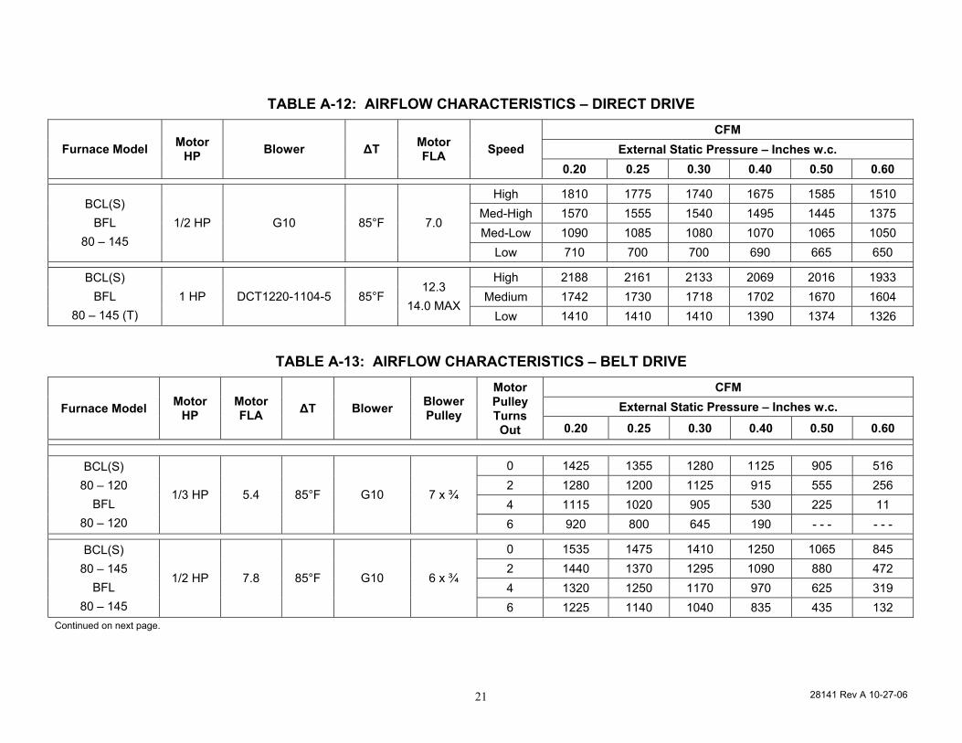
TABLE A-12: AIRFLOW CHARACTERISTICS – DIRECT DRIVE CFM
External Static Pressure – Inches w.c. Furnace Model Motor HP Blower ∆T Motor
FLA Speed 0.20 0.25 0.30 0.40 0.50 0.60
High 1810 1775 1740 1675 1585 1510 Med-High 1570 1555 1540 1495 1445 1375 Med-Low 1090 1085 1080 1070 1065 1050
BCL(S) BFL
80 – 145 1/2 HP G10 85°F 7.0
Low 710 700 700 690 665 650
High 2188 2161 2133 2069 2016 1933 Medium 1742 1730 1718 1702 1670 1604
BCL(S) BFL
80 – 145 (T) 1 HP DCT1220-1104-5 85°F
12.3 14.0 MAX
Low 1410 1410 1410 1390 1374 1326
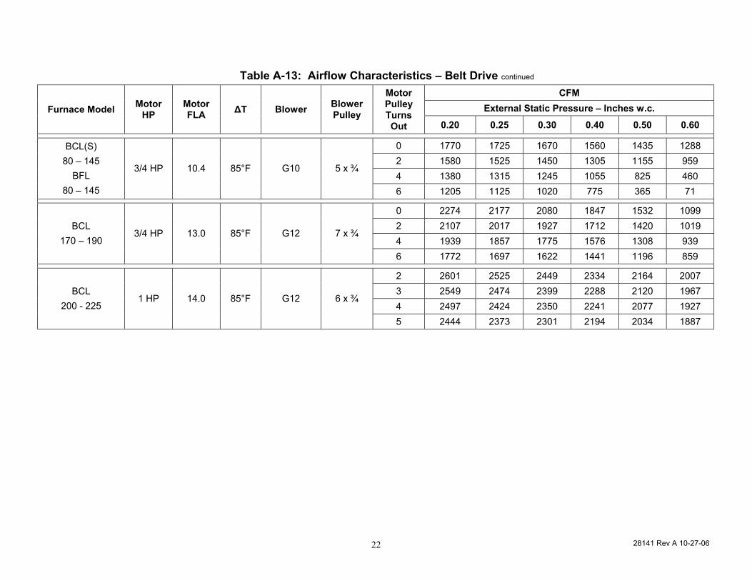
TABLE A-13: AIRFLOW CHARACTERISTICS – BELT DRIVE CFM
External Static Pressure – Inches w.c. Furnace Model Motor HP
Motor FLA ∆T Blower Blower
Pulley
Motor Pulley Turns Out 0.20 0.25 0.30 0.40 0.50 0.60
0 1425 1355 1280 1125 905 516 2 1280 1200 1125 915 555 256 4 1115 1020 905 530 225 11
BCL(S) 80 – 120
BFL 80 – 120
1/3 HP 5.4 85°F G10 7 x ¾
6 920 800 645 190 - - - - - -
0 1535 1475 1410 1250 1065 845 2 1440 1370 1295 1090 880 472 4 1320 1250 1170 970 625 319
BCL(S) 80 – 145
BFL 80 – 145
1/2 HP 7.8 85°F G10 6 x ¾
6 1225 1140 1040 835 435 132 Continued on next page.
28141 Rev A 10-27-06 22
Table A-13: Airflow Characteristics – Belt Drive continued CFM
External Static Pressure – Inches w.c. Furnace Model Motor HP
Motor FLA ∆T Blower Blower
Pulley
Motor Pulley Turns Out 0.20 0.25 0.30 0.40 0.50 0.60
0 1770 1725 1670 1560 1435 1288 2 1580 1525 1450 1305 1155 959 4 1380 1315 1245 1055 825 460
BCL(S) 80 – 145
BFL 80 – 145
3/4 HP 10.4 85°F G10 5 x ¾
6 1205 1125 1020 775 365 71
0 2274 2177 2080 1847 1532 1099 2 2107 2017 1927 1712 1420 1019 4 1939 1857 1775 1576 1308 939
BCL 170 – 190
3/4 HP 13.0 85°F G12 7 x ¾
6 1772 1697 1622 1441 1196 859
2 2601 2525 2449 2334 2164 2007 3 2549 2474 2399 2288 2120 1967 4 2497 2424 2350 2241 2077 1927
BCL 200 - 225
1 HP 14.0 85°F G12 6 x ¾
5 2444 2373 2301 2194 2034 1887
28141 Rev A 10-27-06 23
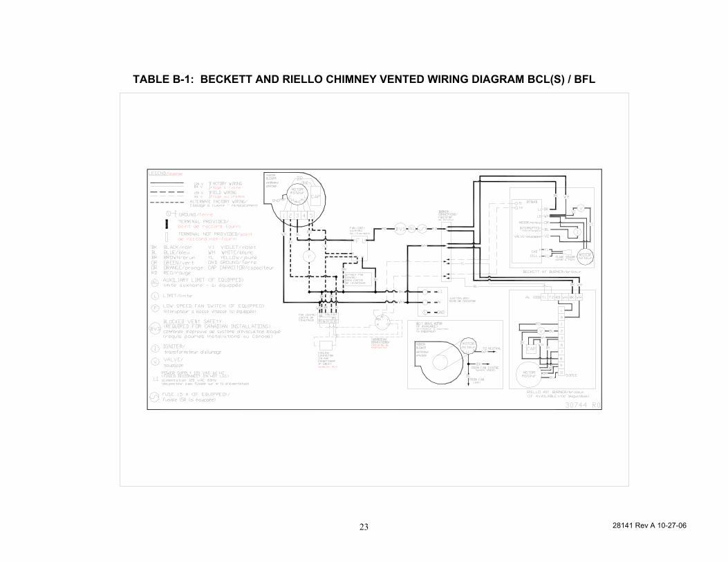
TABLE B-1: BECKETT AND RIELLO CHIMNEY VENTED WIRING DIAGRAM BCL(S) / BFL
28141 Rev A 10-27-06 24
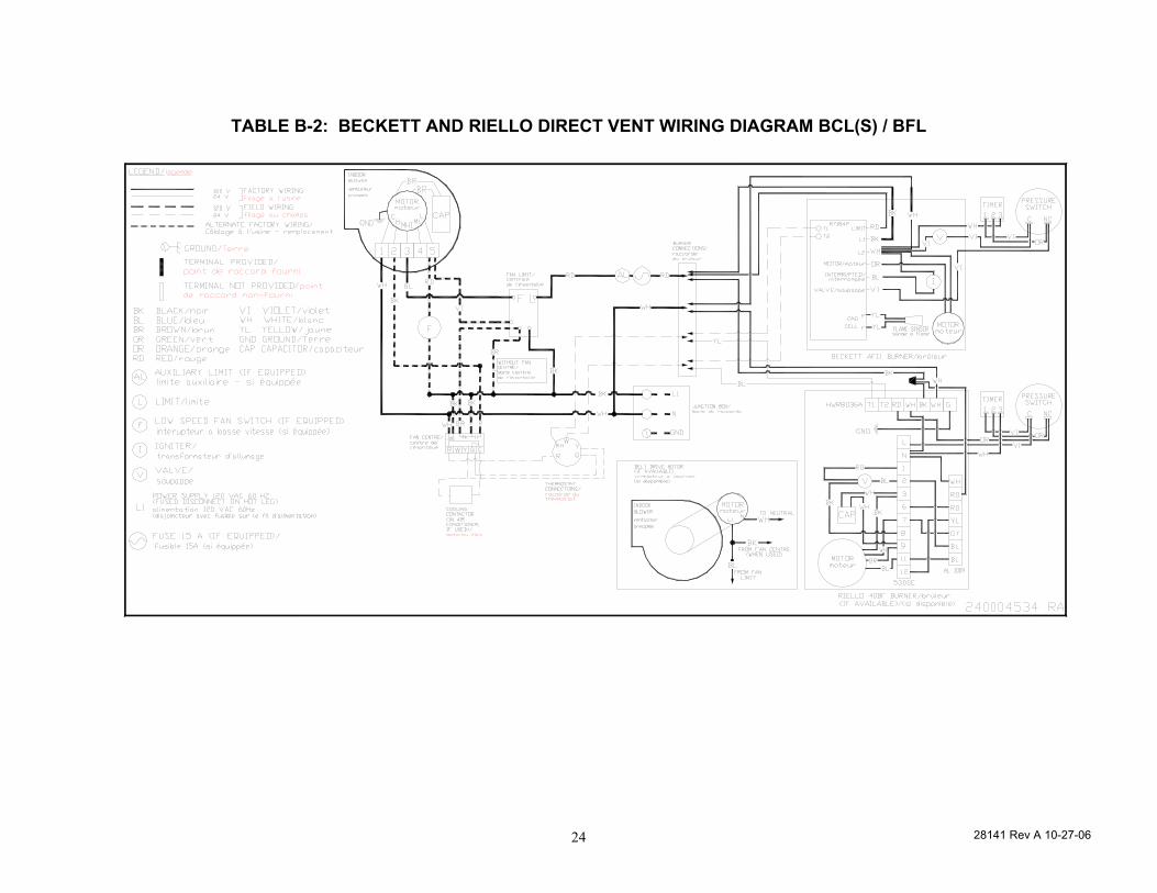
TABLE B-2: BECKETT AND RIELLO DIRECT VENT WIRING DIAGRAM BCL(S) / BFL
28141 Rev A 10-27-06 25
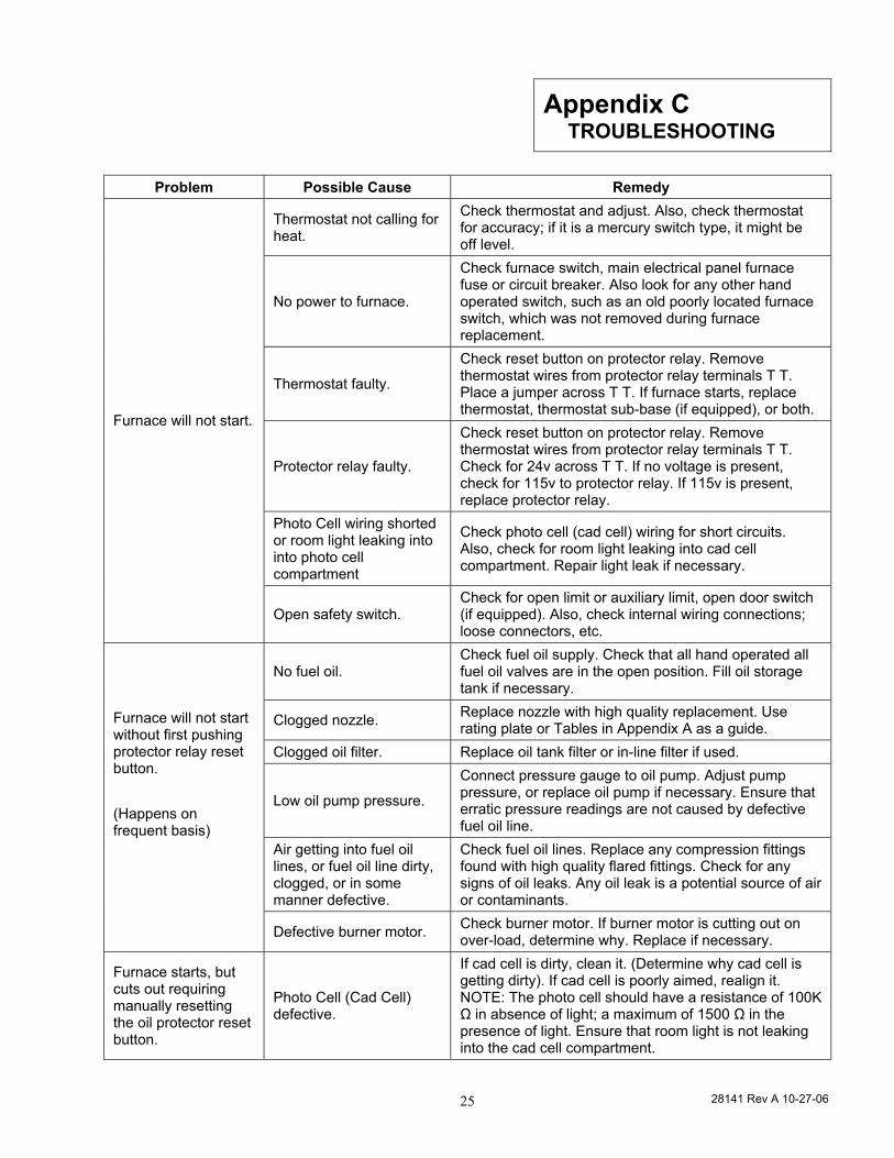
Appendix C TROUBLESHOOTING
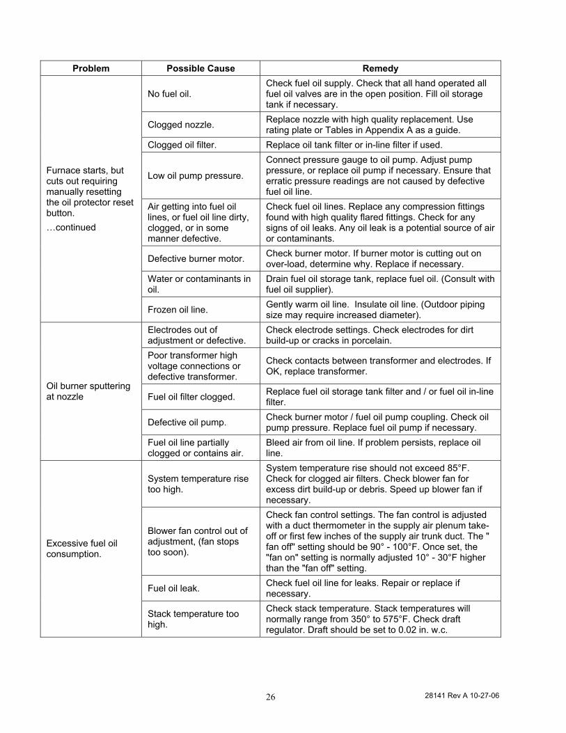
Problem Possible Cause Remedy
Thermostat not calling for heat.
Check thermostat and adjust. Also, check thermostat for accuracy; if it is a mercury switch type, it might be off level.
No power to furnace.
Check furnace switch, main electrical panel furnace fuse or circuit breaker. Also look for any other hand operated switch, such as an old poorly located furnace switch, which was not removed during furnace replacement.
Thermostat faulty.
Check reset button on protector relay. Remove thermostat wires from protector relay terminals T T. Place a jumper across T T. If furnace starts, replace thermostat, thermostat sub-base (if equipped), or both.
Protector relay faulty.
Check reset button on protector relay. Remove thermostat wires from protector relay terminals T T. Check for 24v across T T. If no voltage is present, check for 115v to protector relay. If 115v is present, replace protector relay.
Photo Cell wiring shorted or room light leaking into into photo cell compartment
Check photo cell (cad cell) wiring for short circuits. Also, check for room light leaking into cad cell compartment. Repair light leak if necessary.
Furnace will not start.
Open safety switch. Check for open limit or auxiliary limit, open door switch (if equipped). Also, check internal wiring connections; loose connectors, etc.
No fuel oil. Check fuel oil supply. Check that all hand operated all fuel oil valves are in the open position. Fill oil storage tank if necessary.
Clogged nozzle. Replace nozzle with high quality replacement. Use rating plate or Tables in Appendix A as a guide.
Clogged oil filter. Replace oil tank filter or in-line filter if used.
Low oil pump pressure.
Connect pressure gauge to oil pump. Adjust pump pressure, or replace oil pump if necessary. Ensure that erratic pressure readings are not caused by defective fuel oil line.
Air getting into fuel oil lines, or fuel oil line dirty, clogged, or in some manner defective.
Check fuel oil lines. Replace any compression fittings found with high quality flared fittings. Check for any signs of oil leaks. Any oil leak is a potential source of air or contaminants.
Furnace will not start without first pushing protector relay reset button. (Happens on frequent basis)
Defective burner motor. Check burner motor. If burner motor is cutting out on over-load, determine why. Replace if necessary.
Furnace starts, but cuts out requiring manually resetting the oil protector reset button.
Photo Cell (Cad Cell) defective.
If cad cell is dirty, clean it. (Determine why cad cell is getting dirty). If cad cell is poorly aimed, realign it. NOTE: The photo cell should have a resistance of 100K Ω in absence of light; a maximum of 1500 Ω in the presence of light. Ensure that room light is not leaking into the cad cell compartment.
28141 Rev A 10-27-06 26
Problem Possible Cause Remedy
No fuel oil. Check fuel oil supply. Check that all hand operated all fuel oil valves are in the open position. Fill oil storage tank if necessary.
Clogged nozzle. Replace nozzle with high quality replacement. Use rating plate or Tables in Appendix A as a guide.
Clogged oil filter. Replace oil tank filter or in-line filter if used.
Low oil pump pressure.
Connect pressure gauge to oil pump. Adjust pump pressure, or replace oil pump if necessary. Ensure that erratic pressure readings are not caused by defective fuel oil line.
Air getting into fuel oil lines, or fuel oil line dirty, clogged, or in some manner defective.
Check fuel oil lines. Replace any compression fittings found with high quality flared fittings. Check for any signs of oil leaks. Any oil leak is a potential source of air or contaminants.
Defective burner motor. Check burner motor. If burner motor is cutting out on over-load, determine why. Replace if necessary.
Water or contaminants in oil.
Drain fuel oil storage tank, replace fuel oil. (Consult with fuel oil supplier).
Furnace starts, but cuts out requiring manually resetting the oil protector reset button. …continued
Frozen oil line. Gently warm oil line. Insulate oil line. (Outdoor piping size may require increased diameter).
Electrodes out of adjustment or defective.
Check electrode settings. Check electrodes for dirt build-up or cracks in porcelain.
Poor transformer high voltage connections or defective transformer.
Check contacts between transformer and electrodes. If OK, replace transformer.
Fuel oil filter clogged. Replace fuel oil storage tank filter and / or fuel oil in-line filter.
Defective oil pump. Check burner motor / fuel oil pump coupling. Check oil pump pressure. Replace fuel oil pump if necessary.
Oil burner sputtering at nozzle
Fuel oil line partially clogged or contains air.
Bleed air from oil line. If problem persists, replace oil line.
System temperature rise too high.
System temperature rise should not exceed 85°F. Check for clogged air filters. Check blower fan for excess dirt build-up or debris. Speed up blower fan if necessary.
Blower fan control out of adjustment, (fan stops too soon).
Check fan control settings. The fan control is adjusted with a duct thermometer in the supply air plenum take-off or first few inches of the supply air trunk duct. The " fan off" setting should be 90° - 100°F. Once set, the "fan on" setting is normally adjusted 10° - 30°F higher than the "fan off" setting.
Fuel oil leak. Check fuel oil line for leaks. Repair or replace if necessary.
Excessive fuel oil consumption.
Stack temperature too high.
Check stack temperature. Stack temperatures will normally range from 350° to 575°F. Check draft regulator. Draft should be set to 0.02 in. w.c.
28141 Rev A 10-27-06 27
Problem Possible Cause Remedy
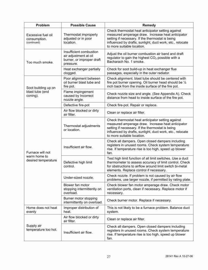
Excessive fuel oil consumption. (continued)
Thermostat improperly adjusted or in poor location.
Check thermostat heat anticipator setting against measured amperage draw. Increase heat anticipator setting if necessary. If the thermostat is being influenced by drafts, sunlight, duct work, etc., relocate to more suitable location.
Insufficient combustion air adjustment at oil burner, or improper draft pressure.
Adjust the oil burner combustion air band and draft regulator to gain the highest CO2 possible with a Bacharach No. 1 smoke. Too much smoke.
Heat exchanger partially clogged.
Check for soot build-up in heat exchanger flue passages, especially in the outer radiator.
Poor alignment between oil burner blast tube and fire pot.
Check alignment. blast tube should be centered with fire pot burner opening. Oil burner head should be ¼ inch back from the inside surface of the fire pot.
Flame impingement caused by Incorrect nozzle angle.
Check nozzle size and angle. (See Appendix A). Check distance from head to inside surface of the fire pot.
Soot building up on blast tube (end coning).
Defective fire-pot Check fire-pot. Repair or replace. Air flow blocked or dirty air filter. Clean or replace air filter.
Thermostat adjustments or location.
Check thermostat heat anticipator setting against measured amperage draw. Increase heat anticipator setting if necessary. If the thermostat is being influenced by drafts, sunlight, duct work, etc., relocate to more suitable location.
Insufficient air flow.
Check all dampers. Open closed dampers including registers in unused rooms. Check system temperature rise. If temperature rise is too high, speed up blower fan.
Defective high limit control.
Test high limit function of all limit switches. Use a duct thermometer to assess accuracy of limit control. Check for obstructions to airflow around limit switch bi-metal elements. Replace control if necessary.
Under-sized nozzle. Check nozzle. If problem is not caused by air flow problems, use larger nozzle, if permitted by rating plate.
Blower fan motor stopping intermittently on overload.
Check blower fan motor amperage draw. Check motor ventilation ports, clean if necessary. Replace motor if necessary.
Furnace will not warm home to desired temperature
Burner motor stopping intermittently on overload. Check burner motor. Replace if necessary.
Home does not heat evenly
Improper distribution of heat.
This is not likely to be a furnace problem. Balance duct system.
Air flow blocked or dirty air filter. Clean or replace air filter.
Supply air temperature too hot.
Insufficient air flow.
Check all dampers. Open closed dampers including registers in unused rooms. Check system temperature rise. If temperature rise is too high, speed up blower fan.
28141 Rev A 10-27-06 28
Problem Possible Cause Remedy
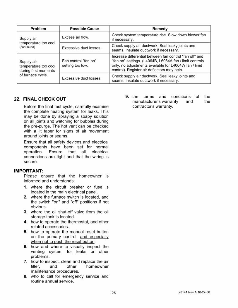
Excess air flow. Check system temperature rise. Slow down blower fan if necessary. Supply air
temperature too cool. (continued) Excessive duct losses. Check supply air ductwork. Seal leaky joints and
seams. Insulate ductwork if necessary.
Fan control "fan on" setting too low.
Increase differential between fan control "fan off" and "fan on" settings. (L4064B, L6064A fan / limit controls only, no adjustments available for L4064W fan / limit control). Register air deflectors may help.
Supply air temperature too cool during first moments of furnace cycle.
Excessive duct losses. Check supply air ductwork. Seal leaky joints and seams. Insulate ductwork if necessary.
22. FINAL CHECK OUT Before the final test cycle, carefully examine the complete heating system for leaks. This may be done by spraying a soapy solution on all joints and watching for bubbles during the pre-purge. The hot vent can be checked with a lit taper for signs of air movement around joints or seams. Ensure that all safety devices and electrical components have been set for normal operation. Ensure that all electrical connections are tight and that the wiring is secure.
IMPORTANT: Please ensure that the homeowner is informed and understands: 1. where the circuit breaker or fuse is
located in the main electrical panel. 2. where the furnace switch is located, and
the switch "on" and "off" positions if not obvious.
3. where the oil shut-off valve from the oil storage tank is located.
4. how to operate the thermostat, and other related accessories.
5. how to operate the manual reset button on the primary control, and especially when not to push the reset button.
6. how and where to visually inspect the venting system for leaks or other problems.
7. how to inspect, clean and replace the air filter, and other homeowner maintenance procedures.
8. who to call for emergency service and routine annual service.
9. the terms and conditions of the manufacturer's warranty and the contractor's warranty.
29809 Rev A 10/19/2006 29
29809 Rev A 10/19/2006 30
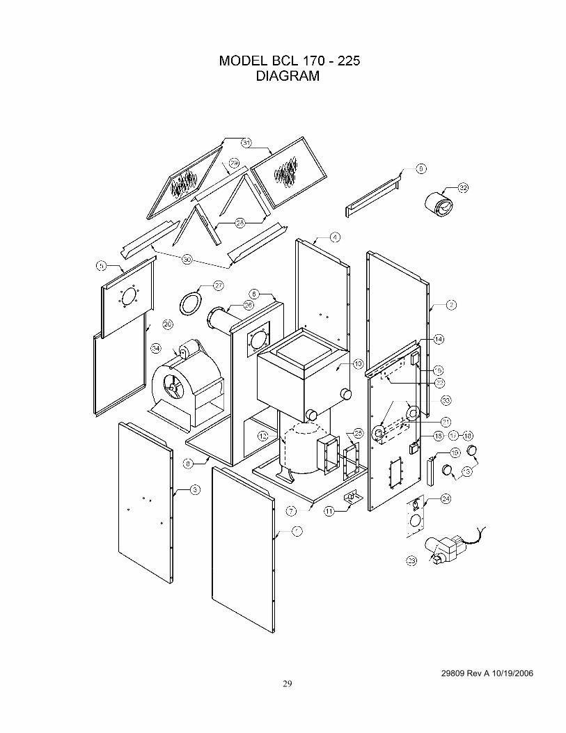
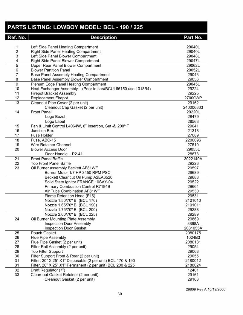
PARTS LISTING: LOWBOY MODEL: BCL - 190 / 225
Ref. No. Description Part No.
1 Left Side Panel Heating Compartment 29040L 2 Right Side Panel Heating Compartment 29040L 3 Left Side Panel Blower Compartment 29048L 4 Right Side Panel Blower Compartment 29047L 5 Upper Rear Panel Blower Compartment 29062L 6 Blower Partition Panel 29052L 7 Base Panel Assembly Heating Compartment 29043 8 Base Panel Assembly Blower Compartment 29056 9 Plenum Edge Panel Heating Compartment 29045L
10 Heat Exchanger Assembly (Prior to ser#BCUL66150 use 1018B4) 29224 11 Firepot Bracket Assembly 29225 12 Replacement Firepot 27000WP 13 Cleanout Pipe Cover (2 per unit) 29162
Cleanout Cap Gasket (2 per unit) 240006333 14 Front Panel 29220L
Logo Bezel 28479 Logo Label 28563
15 Fan & Limit Control L4064W, 8” Insertion, Set @ 200º F 29041 16 Junction Box 21318 17 Fuse Holder 27089 18 Fuse, ABC-15 2200096 19 Wire Retainer Channel 27510 20 Blower Access Door 29053L
Door Handle – P2-41 28673 21 Front Panel Baffle 3022140A 22 Top Front Panel Baffle 29223 23 Oil Burner assembly Beckett AF81WF 29597
Burner Motor 1/7 HP 3450 RPM PSC 29689 Beckett Cleancut Oil Pump A2EA6520 29688 Solid State Ignitor FRANCE 10SAY-04 29522 Primary Combustion Control R7184B 29664 Air Tube Combination AF81WF 29530 Flame Retention Head (F16) 29531 Nozzle 1.50/70º B (BCL 170) 2101010 Nozzle 1.65/70º B (BCL 190) 2101011 Nozzle 1.75/70º B (BCL 200) 29288 Nozzle 2.00/70º B (BCL 225) 29289
24 Oil Burner Mounting Plate Assembly 29869 Inspection Door Assembly 8898A Inspection Door Gasket 2081055A
25 Pouch Gasket 2080175 26 Flue Pipe Assembly 1024B3 27 Flue Pipe Gasket (2 per unit) 2080181 28 Filter Rail Assembly (2 per unit) 29054 29 Top Filter Support 29063 30 Filter Support Front & Rear (2 per unit) 29055 31 Filter, 20” X 25” X1” Disposable (2 per unit) BCL 170 & 190 2180012 31 Filter, 20” X 25” X1” Permanent (2 per unit) BCL 200 & 225 2180024 32 Draft Regulator (7”) 12401 33 Clean-out Gasket Retainer (2 per unit) 29161
Cleanout Gasket (2 per unit) 29163
29809 Rev A 10/19/2006 31
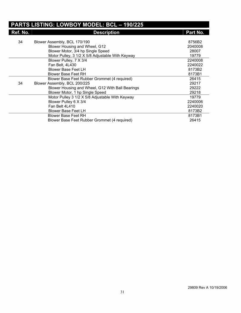
PARTS LISTING: LOWBOY MODEL: BCL – 190/225 Ref. No. Description Part No.
34 Blower Assembly, BCL 170/190 8756B2 Blower Housing and Wheel, G12 2040008 Blower Motor, 3/4 hp Single Speed 28007 Motor Pulley, 3 1/2 X 5/8 Adjustable With Keyway 19779 Blower Pulley, 7 X 3/4 2240008 Fan Belt, 4L430 2240022 Blower Base Feet LH 8173B2 Blower Base Feet RH 8173B1 Blower Base Feet Rubber Grommet (4 required) 26415
34 Blower Assembly, BCL 200/225 29217 Blower Housing and Wheel, G12 With Ball Bearings 29222 Blower Motor, 1 hp Single Speed 29218 Motor Pulley 3 1/2 X 5/8 Adjustable With Keyway 19779 Blower Pulley 6 X 3/4 2240006 Fan Belt 4L410 2240020 Blower Base Feet LH 8173B2 Blower Base Feet RH 8173B1 Blower Base Feet Rubber Grommet (4 required) 26415
29809 Rev A 10/19/2006 32
29809 Rev A 10/19/2006 33
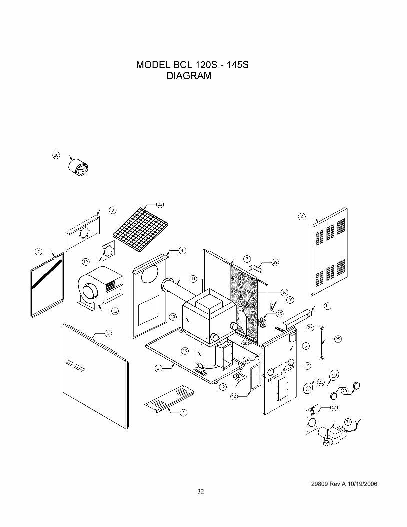
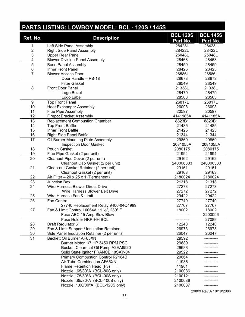
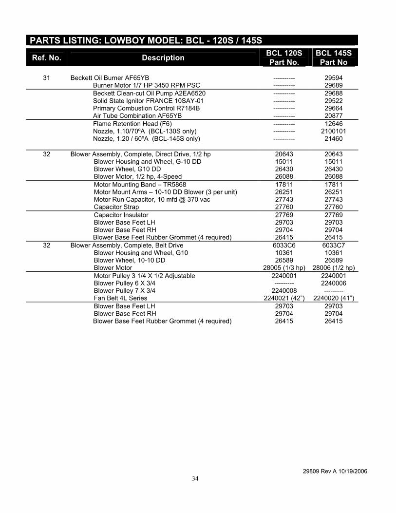
PARTS LISTING: LOWBOY MODEL: BCL - 120S / 145S
Ref. No. Description BCL 120S Part No.
BCL 145S Part No.
1 Left Side Panel Assembly 28423L 28423L 2 Right Side Panel Assembly 28422L 28422L 3 Upper Rear Panel 26048L 26048L 4 Blower Division Panel Assembly 28468 28468 5 Base Panel Assembly 28459 28459 6 Inner Front Panel 28425 28425 7 Blower Access Door 26586L 26586L Door Handle – PS-18 28673 28673 Filter Gasket 28549 28549
8 Front Door Panel 21338L 21338L Logo Bezel 28479 28479 Logo Label 28563 28563
9 Top Front Panel 26017L 26017L 10 Heat Exchanger Assembly 26098 26098 11 Flue Pipe Assembly 20597 20597 12 Firepot Bracket Assembly 4141185A 4141185A 13 Replacement Combustion Chamber 8823B1 8823B1 14 Top Front Baffle 21485 21485 15 Inner Front Baffle 21425 21425 16 Right Side Panel Baffle 21344 21344 17 Oil Burner Mounting Plate Assembly 29869 29869
Inspection Door Gasket 2081055A 2081055A 18 Pouch Gasket 2080175 2080175 19 Flue Pipe Gasket (2 per unit) 21994 21994 20 Cleanout Pipe Cover (2 per unit) 29162 29162
Cleanout Cap Gasket (2 per unit) 240006333 240006333 21 Clean-out Gasket Retainer (2 per unit) 29161 29161
Cleanout Gasket (2 per unit) 29163 29163 22 Air Filter – 20 x 25 x 1 (Permanent) 2180024 2180024 23 Junction Box 21318 21318 24 Wire Harness Blower Direct Drive 27273 27273
Wire Harness Blower Belt Drive 27272 27272 25 Wire Harness Fan & Limit 29422 29422 26 Fan Centre 27740 27740
27740 Replacement Relay 9400-04Q1999 27767 27767 27 Fan & Limit Control L6064A 11 ½”, 230º F 18002 18002
Fuse ABC 15 Amp Slow Blow ---------- 2200096 Fuse Holder HKP-HH BCL ---------- 27089
28 Draft Regulator 6” 12240 12240 29 Fan & Limit Support / Insulation Retainer 26973 26973 30 Side Panel Insulation Retainer (2 per unit) 26047 26047 31 Beckett Oil Burner AF65XN 29592 ----------
Burner Motor 1/7 HP 3450 RPM PSC 29689 ---------- Beckett Clean-cut Oil Pump A2EA6520 29688 ---------- Solid State Ignitor FRANCE 10SAY-04 29522 ---------- Primary Combustion Control R7184B 29664 ---------- Air Tube Combination AF65XN 11986 ---------- Flame Retention Head (F3) 11961 ---------- Nozzle, .65/80ºA (BCL-80S only) 2100086 ---------- Nozzle, .75/80ºA (BCL-90S only) 2100121 ---------- Nozzle, .85/80ºA (BCL-100S only) 2100036 ---------- Nozzle, 1.00/80ºA (BCL-120S only) 2100037 ----------
29809 Rev A 10/19/2006 34
PARTS LISTING: LOWBOY MODEL: BCL - 120S / 145S
Ref. No. Description BCL 120S Part No.
BCL 145S Part No
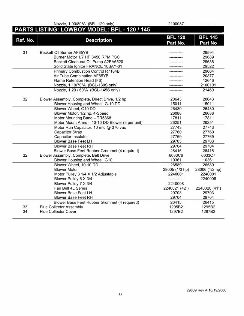
31 Beckett Oil Burner AF65YB ---------- 29594
Burner Motor 1/7 HP 3450 RPM PSC ---------- 29689 Beckett Clean-cut Oil Pump A2EA6520 ---------- 29688 Solid State Ignitor FRANCE 10SAY-01 ---------- 29522 Primary Combustion Control R7184B ---------- 29664 Air Tube Combination AF65YB ---------- 20877 Flame Retention Head (F6) ---------- 12646 Nozzle, 1.10/70ºA (BCL-130S only) ---------- 2100101 Nozzle, 1.20 / 60ºA (BCL-145S only) ---------- 21460
32 Blower Assembly, Complete, Direct Drive, 1/2 hp 20643 20643 Blower Housing and Wheel, G-10 DD 15011 15011 Blower Wheel, G10 DD 26430 26430 Blower Motor, 1/2 hp, 4-Speed 26088 26088 Motor Mounting Band – TR5868 17811 17811 Motor Mount Arms – 10-10 DD Blower (3 per unit) 26251 26251 Motor Run Capacitor, 10 mfd @ 370 vac 27743 27743 Capacitor Strap 27760 27760 Capacitor Insulator 27769 27769 Blower Base Feet LH 29703 29703 Blower Base Feet RH 29704 29704 Blower Base Feet Rubber Grommet (4 required) 26415 26415
32 Blower Assembly, Complete, Belt Drive 6033C6 6033C7 Blower Housing and Wheel, G10 10361 10361 Blower Wheel, 10-10 DD 26589 26589 Blower Motor 28005 (1/3 hp) 28006 (1/2 hp) Motor Pulley 3 1/4 X 1/2 Adjustable 2240001 2240001 Blower Pulley 6 X 3/4 --------- 2240006 Blower Pulley 7 X 3/4 2240008 --------- Fan Belt 4L Series 2240021 (42”) 2240020 (41”) Blower Base Feet LH 29703 29703 Blower Base Feet RH 29704 29704 Blower Base Feet Rubber Grommet (4 required) 26415 26415
29809 Rev A 10/19/2006 35
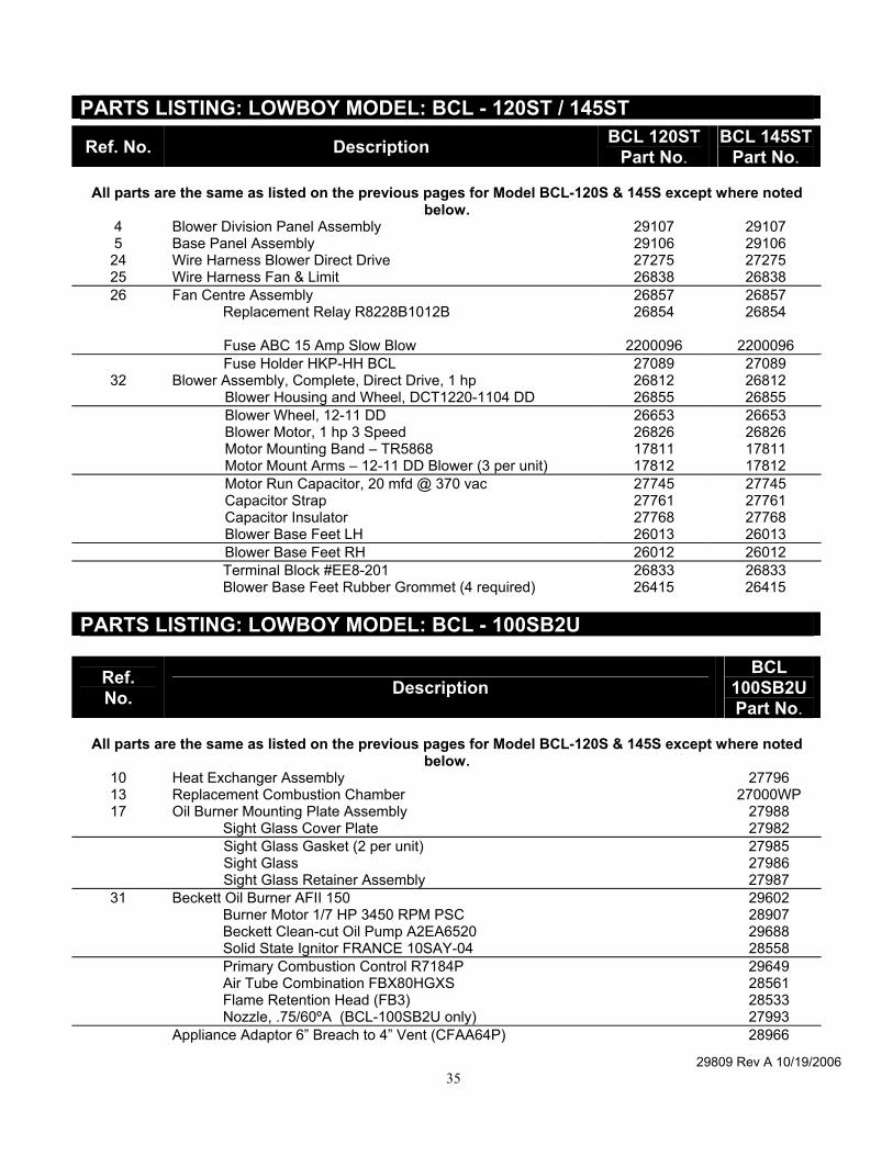
PARTS LISTING: LOWBOY MODEL: BCL - 120ST / 145ST
Ref. No. Description BCL 120ST Part No.
BCL 145ST Part No.
All parts are the same as listed on the previous pages for Model BCL-120S & 145S except where noted
below. 4 Blower Division Panel Assembly 29107 29107 5 Base Panel Assembly 29106 29106 24 Wire Harness Blower Direct Drive 27275 27275 25 Wire Harness Fan & Limit 26838 26838 26 Fan Centre Assembly 26857 26857
Replacement Relay R8228B1012B 26854 26854 Fuse ABC 15 Amp Slow Blow 2200096 2200096 Fuse Holder HKP-HH BCL 27089 27089
32 Blower Assembly, Complete, Direct Drive, 1 hp 26812 26812 Blower Housing and Wheel, DCT1220-1104 DD 26855 26855 Blower Wheel, 12-11 DD 26653 26653 Blower Motor, 1 hp 3 Speed 26826 26826 Motor Mounting Band – TR5868 17811 17811 Motor Mount Arms – 12-11 DD Blower (3 per unit) 17812 17812 Motor Run Capacitor, 20 mfd @ 370 vac 27745 27745 Capacitor Strap 27761 27761 Capacitor Insulator 27768 27768 Blower Base Feet LH 26013 26013 Blower Base Feet RH 26012 26012 Terminal Block #EE8-201 26833 26833 Blower Base Feet Rubber Grommet (4 required) 26415 26415
PARTS LISTING: LOWBOY MODEL: BCL - 100SB2U
Ref. No. Description
BCL 100SB2U Part No.
All parts are the same as listed on the previous pages for Model BCL-120S & 145S except where noted
below. 10 Heat Exchanger Assembly 27796 13 Replacement Combustion Chamber 27000WP 17 Oil Burner Mounting Plate Assembly 27988
Sight Glass Cover Plate 27982 Sight Glass Gasket (2 per unit) 27985 Sight Glass 27986 Sight Glass Retainer Assembly 27987
31 Beckett Oil Burner AFII 150 29602 Burner Motor 1/7 HP 3450 RPM PSC 28907 Beckett Clean-cut Oil Pump A2EA6520 29688 Solid State Ignitor FRANCE 10SAY-04 28558 Primary Combustion Control R7184P 29649 Air Tube Combination FBX80HGXS 28561 Flame Retention Head (FB3) 28533 Nozzle, .75/60ºA (BCL-100SB2U only) 27993 Appliance Adaptor 6” Breach to 4” Vent (CFAA64P) 28966
29809 Rev A 10/19/2006 36
29809 Rev A 10/19/2006 37
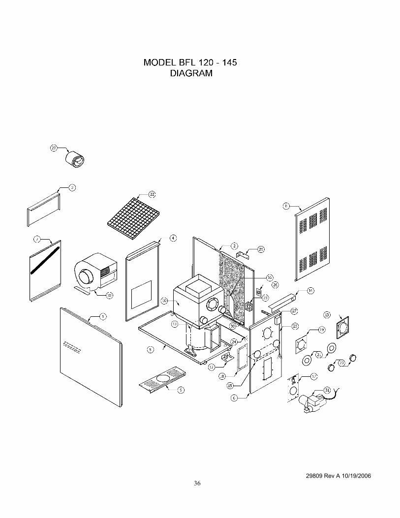
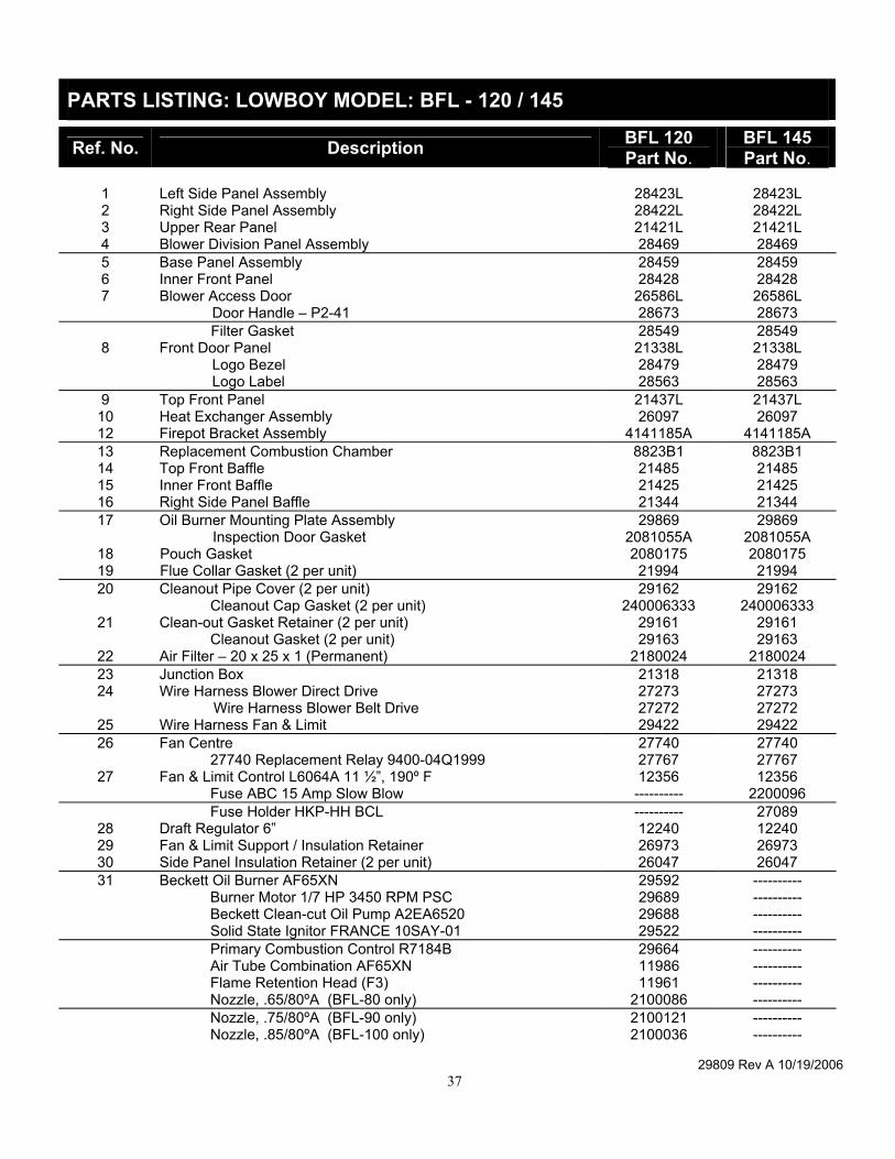
PARTS LISTING: LOWBOY MODEL: BFL - 120 / 145
Ref. No. Description BFL 120 Part No.
BFL 145 Part No.
1 Left Side Panel Assembly 28423L 28423L 2 Right Side Panel Assembly 28422L 28422L 3 Upper Rear Panel 21421L 21421L 4 Blower Division Panel Assembly 28469 28469 5 Base Panel Assembly 28459 28459 6 Inner Front Panel 28428 28428 7 Blower Access Door 26586L 26586L Door Handle – P2-41 28673 28673 Filter Gasket 28549 28549
8 Front Door Panel 21338L 21338L Logo Bezel 28479 28479 Logo Label 28563 28563
9 Top Front Panel 21437L 21437L 10 Heat Exchanger Assembly 26097 26097 12 Firepot Bracket Assembly 4141185A 4141185A 13 Replacement Combustion Chamber 8823B1 8823B1 14 Top Front Baffle 21485 21485 15 Inner Front Baffle 21425 21425 16 Right Side Panel Baffle 21344 21344 17 Oil Burner Mounting Plate Assembly 29869 29869
Inspection Door Gasket 2081055A 2081055A 18 Pouch Gasket 2080175 2080175 19 Flue Collar Gasket (2 per unit) 21994 21994 20 Cleanout Pipe Cover (2 per unit) 29162 29162
Cleanout Cap Gasket (2 per unit) 240006333 240006333 21 Clean-out Gasket Retainer (2 per unit) 29161 29161
Cleanout Gasket (2 per unit) 29163 29163 22 Air Filter – 20 x 25 x 1 (Permanent) 2180024 2180024 23 Junction Box 21318 21318 24 Wire Harness Blower Direct Drive 27273 27273
Wire Harness Blower Belt Drive 27272 27272 25 Wire Harness Fan & Limit 29422 29422 26 Fan Centre 27740 27740
27740 Replacement Relay 9400-04Q1999 27767 27767 27 Fan & Limit Control L6064A 11 ½”, 190º F 12356 12356
Fuse ABC 15 Amp Slow Blow ---------- 2200096 Fuse Holder HKP-HH BCL ---------- 27089
28 Draft Regulator 6” 12240 12240 29 Fan & Limit Support / Insulation Retainer 26973 26973 30 Side Panel Insulation Retainer (2 per unit) 26047 26047 31 Beckett Oil Burner AF65XN 29592 ----------
Burner Motor 1/7 HP 3450 RPM PSC 29689 ---------- Beckett Clean-cut Oil Pump A2EA6520 29688 ---------- Solid State Ignitor FRANCE 10SAY-01 29522 ---------- Primary Combustion Control R7184B 29664 ---------- Air Tube Combination AF65XN 11986 ---------- Flame Retention Head (F3) 11961 ---------- Nozzle, .65/80ºA (BFL-80 only) 2100086 ---------- Nozzle, .75/80ºA (BFL-90 only) 2100121 ---------- Nozzle, .85/80ºA (BFL-100 only) 2100036 ----------
29809 Rev A 10/19/2006 38
Nozzle, 1.00/80ºA (BFL-120 only) 2100037 ---------- PARTS LISTING: LOWBOY MODEL: BFL - 120 / 145
Ref. No. Description BFL 120 Part No.
BFL 145 Part No
31 Beckett Oil Burner AF65YB ---------- 29594
Burner Motor 1/7 HP 3450 RPM PSC ---------- 29689 Beckett Clean-cut Oil Pump A2EA6520 ---------- 29688 Solid State Ignitor FRANCE 10SAY-01 ---------- 29522 Primary Combustion Control R7184B ---------- 29664 Air Tube Combination AF65YB ---------- 20877 Flame Retention Head (F6) ---------- 12646 Nozzle, 1.10/70ºA (BCL-130S only) ---------- 2100101 Nozzle, 1.20 / 60ºA (BCL-145S only) ---------- 21460
32 Blower Assembly, Complete, Direct Drive, 1/2 hp 20643 20643 Blower Housing and Wheel, G-10 DD 15011 15011 Blower Wheel, G10 DD 26430 26430 Blower Motor, 1/2 hp, 4-Speed 26088 26088 Motor Mounting Band – TR5868 17811 17811 Motor Mount Arms – 10-10 DD Blower (3 per unit) 26251 26251 Motor Run Capacitor, 10 mfd @ 370 vac 27743 27743 Capacitor Strap 27760 27760 Capacitor Insulator 27769 27769 Blower Base Feet LH 29703 29703 Blower Base Feet RH 29704 29704 Blower Base Feet Rubber Grommet (4 required) 26415 26415
32 Blower Assembly, Complete, Belt Drive 6033C6 6033C7 Blower Housing and Wheel, G10 10361 10361 Blower Wheel, 10-10 DD 26589 26589 Blower Motor 28005 (1/3 hp) 28006 (1/2 hp) Motor Pulley 3 1/4 X 1/2 Adjustable 2240001 2240001 Blower Pulley 6 X 3/4 --------- 2240006 Blower Pulley 7 X 3/4 2240008 --------- Fan Belt 4L Series 2240021 (42”) 2240020 (41”) Blower Base Feet LH 29703 29703 Blower Base Feet RH 29704 29704 Blower Base Feet Rubber Grommet (4 required) 26415 26415
33 Flue Collector Assembly 1295B2 1295B2 34 Flue Collector Cover 1297B2 1297B2
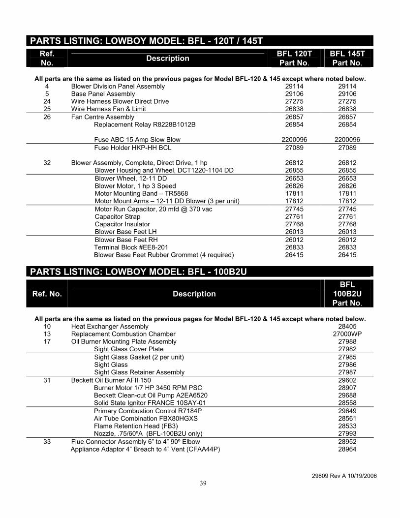
29809 Rev A 10/19/2006 39
PARTS LISTING: LOWBOY MODEL: BFL - 120T / 145T Ref. No. Description BFL 120T
Part No. BFL 145T Part No.
All parts are the same as listed on the previous pages for Model BFL-120 & 145 except where noted below.
4 Blower Division Panel Assembly 29114 29114 5 Base Panel Assembly 29106 29106 24 Wire Harness Blower Direct Drive 27275 27275 25 Wire Harness Fan & Limit 26838 26838 26 Fan Centre Assembly 26857 26857
Replacement Relay R8228B1012B 26854 26854 Fuse ABC 15 Amp Slow Blow 2200096 2200096 Fuse Holder HKP-HH BCL 27089 27089
32 Blower Assembly, Complete, Direct Drive, 1 hp 26812 26812 Blower Housing and Wheel, DCT1220-1104 DD 26855 26855 Blower Wheel, 12-11 DD 26653 26653 Blower Motor, 1 hp 3 Speed 26826 26826 Motor Mounting Band – TR5868 17811 17811 Motor Mount Arms – 12-11 DD Blower (3 per unit) 17812 17812 Motor Run Capacitor, 20 mfd @ 370 vac 27745 27745 Capacitor Strap 27761 27761 Capacitor Insulator 27768 27768 Blower Base Feet LH 26013 26013 Blower Base Feet RH 26012 26012 Terminal Block #EE8-201 26833 26833 Blower Base Feet Rubber Grommet (4 required) 26415 26415
PARTS LISTING: LOWBOY MODEL: BFL - 100B2U
Ref. No. Description BFL
100B2U Part No.
All parts are the same as listed on the previous pages for Model BFL-120 & 145 except where noted below.
10 Heat Exchanger Assembly 28405 13 Replacement Combustion Chamber 27000WP 17 Oil Burner Mounting Plate Assembly 27988
Sight Glass Cover Plate 27982 Sight Glass Gasket (2 per unit) 27985 Sight Glass 27986 Sight Glass Retainer Assembly 27987
31 Beckett Oil Burner AFII 150 29602 Burner Motor 1/7 HP 3450 RPM PSC 28907 Beckett Clean-cut Oil Pump A2EA6520 29688 Solid State Ignitor FRANCE 10SAY-01 28558 Primary Combustion Control R7184P 29649 Air Tube Combination FBX80HGXS 28561 Flame Retention Head (FB3) 28533 Nozzle, .75/60ºA (BFL-100B2U only) 27993
33 Flue Connector Assembly 6” to 4” 90º Elbow 28952 Appliance Adaptor 4” Breach to 4” Vent (CFAA44P) 28964
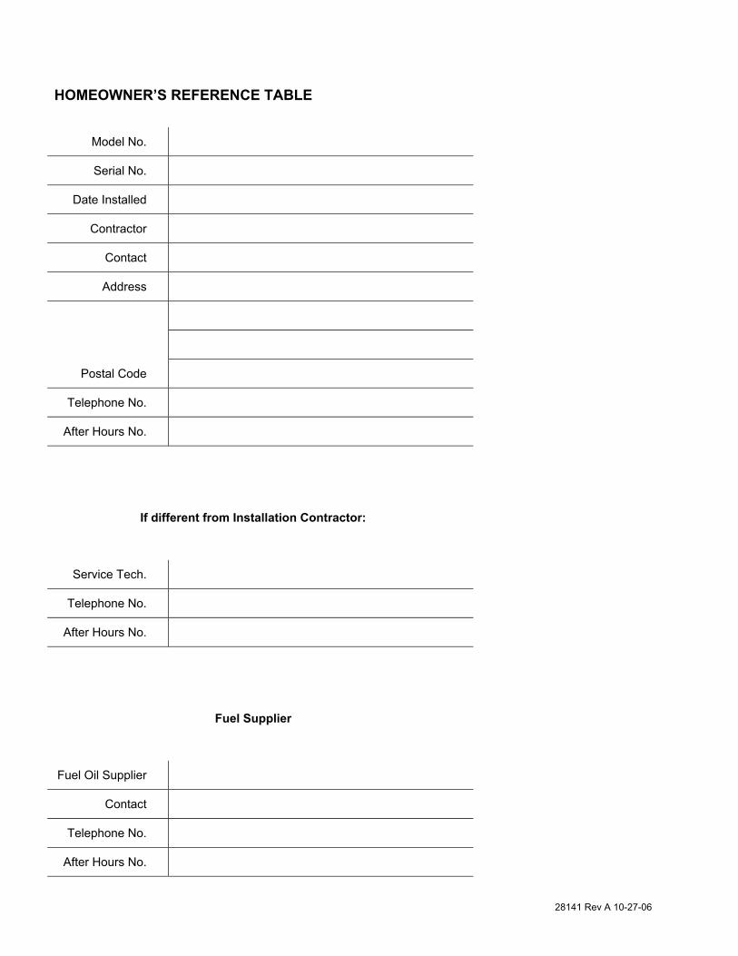
28141 Rev A 10-27-06
HOMEOWNER’S REFERENCE TABLE
Model No.
Serial No.
Date Installed
Contractor
Contact
Address
Postal Code
Telephone No.
After Hours No.
If different from Installation Contractor:
Service Tech.
Telephone No.
After Hours No.
Fuel Supplier
Fuel Oil Supplier
Contact
Telephone No.
After Hours No.
28141 Rev A 10-27-06
NOTES:

28141 Rev A 10-27-06

28141 Rev A 10-27-06

28141 Rev A 10-27-06
6800 Base Line, Wallaceburg, Ontario, N8A 5E5, Can. Tel: (519) 627-0791 Fax: (519) 627-4719
2201 Dwyer Avenue, Utica, New York, 13504, USA. Tel: (315) 797-1310 Fax: (315) 724-9319 85 Middle Road, Dunkirk, New York, 14048, USA Tel: (716) 366-5500 Fax: (716) 366-1209
www.ecrinternational.com