Embed Size (px)
Citation preview

©Copyright Eaton Corp., 2006. All rights reserved.
VC 5001
Installation, Operationand Maintenance ofAirflex® VC Grinding Mill Clutches
Forward this manual to the person responsible for Installation, Operation and Maintenance of the product described herein. Without access to this information, faulty Installation, Operation or Maintenance may result in personal injury or equipment damage.
Use Only Genuine Airflex® Replacement Parts. The Airflex Division of Eaton Corporation recommends the use of genuine Airflex replacement parts. The use of non-genuine Airflex replacement parts could result in substandard product performance, and may void your Eaton warranty. For optimum performance, contactAirflex:
In the U.S.A. and Canada:(800) 233-5926Outside the U.S.A. & Canada: (216) 281-2211Internet: www.airflex.com
November, 1989(Revised: November, 2006)
203676

Table of Contents
1.0 INTRODUCTION . . . . . . . . . . . . . . . . . . . . . . . . . . . . . . . . . . . . . . . . . . . . . . . . . . . . . . . . . . . 2
1.1 Description . . . . . . . . . . . . . . . . . . . . . . . . . . . . . . . . . . . . . . . . . . . . . . . . . . . . . . . . . . . . . . . . . . . . . . . . 2
1.2 How It Works . . . . . . . . . . . . . . . . . . . . . . . . . . . . . . . . . . . . . . . . . . . . . . . . . . . . . . . . . . . . . . . . . . . . . . 2
1.3 Clutch Adjustment . . . . . . . . . . . . . . . . . . . . . . . . . . . . . . . . . . . . . . . . . . . . . . . . . . . . . . . . . . . . . . . . . . 32.0 INSTALLATION. . . . . . . . . . . . . . . . . . . . . . . . . . . . . . . . . . . . . . . . . . . . . . . . . . . . . . . . . . . . 4
2.1 Mounting Arrangements . . . . . . . . . . . . . . . . . . . . . . . . . . . . . . . . . . . . . . . . . . . . . . . . . . . . . . . . . . . . . 4
2.3 Mounting Considerations . . . . . . . . . . . . . . . . . . . . . . . . . . . . . . . . . . . . . . . . . . . . . . . . . . . . . . . . . . . . . 4
2.3 Mounting Spider and Drum Hub . . . . . . . . . . . . . . . . . . . . . . . . . . . . . . . . . . . . . . . . . . . . . . . . . . . . . . . 7
2.4 Shaft Alignment . . . . . . . . . . . . . . . . . . . . . . . . . . . . . . . . . . . . . . . . . . . . . . . . . . . . . . . . . . . . . . . . . . . . 7
2.5 Axial Locking Device Adjustment . . . . . . . . . . . . . . . . . . . . . . . . . . . . . . . . . . . . . . . . . . . . . . . . . . . . . . . 8
2.6 Installation of Element and Drum (Narrow, Dual Narrow and Single Wide) . . . . . . . . . . . . . . . . . . . . . . 9
2.7 Installation of Element and Drums (Dual Wide) . . . . . . . . . . . . . . . . . . . . . . . . . . . . . . . . . . . . . . . . . . . 10
2.8 Air Control System . . . . . . . . . . . . . . . . . . . . . . . . . . . . . . . . . . . . . . . . . . . . . . . . . . . . . . . . . . . . . . . . . 12
2.9 Electrical Controls . . . . . . . . . . . . . . . . . . . . . . . . . . . . . . . . . . . . . . . . . . . . . . . . . . . . . . . . . . . . . . . . . 123.0 OPERATION . . . . . . . . . . . . . . . . . . . . . . . . . . . . . . . . . . . . . . . . . . . . . . . . . . . . . . . . . . . . . 18
3.1 Torque, RPM and Pressure Limits . . . . . . . . . . . . . . . . . . . . . . . . . . . . . . . . . . . . . . . . . . . . . . . . . . . . . 18
3.2 Control Component Adjustment . . . . . . . . . . . . . . . . . . . . . . . . . . . . . . . . . . . . . . . . . . . . . . . . . . . . . . . 184.0 MAINTENANCE . . . . . . . . . . . . . . . . . . . . . . . . . . . . . . . . . . . . . . . . . . . . . . . . . . . . . . . . . . 20
4.1 Periodic Inspection . . . . . . . . . . . . . . . . . . . . . . . . . . . . . . . . . . . . . . . . . . . . . . . . . . . . . . . . . . . . . . . . 20
4.2 Removal of Element Assembly and Drum (Narrow, Dual Narrow and Single Wide) . . . . . . . . . . . . . . . 22
4.3 Removal of Element Assemblies and Drums (Dual Wide) . . . . . . . . . . . . . . . . . . . . . . . . . . . . . . . . . . 22
4.4 Removal of Spider and Drum Hub . . . . . . . . . . . . . . . . . . . . . . . . . . . . . . . . . . . . . . . . . . . . . . . . . . . . . 22
4.5 Disassembly of the Element . . . . . . . . . . . . . . . . . . . . . . . . . . . . . . . . . . . . . . . . . . . . . . . . . . . . . . . . . 22
4.6 Friction Lining Replacement . . . . . . . . . . . . . . . . . . . . . . . . . . . . . . . . . . . . . . . . . . . . . . . . . . . . . . . . . 23
4.7 Assembly of the Element . . . . . . . . . . . . . . . . . . . . . . . . . . . . . . . . . . . . . . . . . . . . . . . . . . . . . . . . . . . . 245.0 SPARE PARTS STORAGE. . . . . . . . . . . . . . . . . . . . . . . . . . . . . . . . . . . . . . . . . . . . . . . . . . 24
5.1 Element Assemblies . . . . . . . . . . . . . . . . . . . . . . . . . . . . . . . . . . . . . . . . . . . . . . . . . . . . . . . . . . . . . . . 24
5.2 Drums . . . . . . . . . . . . . . . . . . . . . . . . . . . . . . . . . . . . . . . . . . . . . . . . . . . . . . . . . . . . . . . . . . . . . . . . . . 24
5.3 Air Actuating Tubes . . . . . . . . . . . . . . . . . . . . . . . . . . . . . . . . . . . . . . . . . . . . . . . . . . . . . . . . . . . . . . . . 246.0 ORDERING INFORMATION/ TECHNICAL ASSISTANCE . . . . . . . . . . . . . . . . . . . . . . . . . 25
6.1 Equipment Reference . . . . . . . . . . . . . . . . . . . . . . . . . . . . . . . . . . . . . . . . . . . . . . . . . . . . . . . . . . . . . . 257.0 PARTS LISTS . . . . . . . . . . . . . . . . . . . . . . . . . . . . . . . . . . . . . . . . . . . . . . . . . . . . . . . . . . . . 26
7.1 Single Narrow Element Assemblies . . . . . . . . . . . . . . . . . . . . . . . . . . . . . . . . . . . . . . . . . . . . . . . . . . . . 26
7.2 Dual Narrow Element Assemblies . . . . . . . . . . . . . . . . . . . . . . . . . . . . . . . . . . . . . . . . . . . . . . . . . . . . . 27
VC 5001 (PDF FORMAT) © Copyright Eaton Corp. 2006, All Rights reserved.

Table of Contents
7.3 Single Wide Element Assemblies . . . . . . . . . . . . . . . . . . . . . . . . . . . . . . . . . . . . . . . . . . . . . . . . . . . . . 28
7.4 Dual Wide Element Assemblies . . . . . . . . . . . . . . . . . . . . . . . . . . . . . . . . . . . . . . . . . . . . . . . . . . . . . . . 29
7.5 Drums . . . . . . . . . . . . . . . . . . . . . . . . . . . . . . . . . . . . . . . . . . . . . . . . . . . . . . . . . . . . . . . . . . . . . . . . . . 29
7.6 Axial Locking Devices . . . . . . . . . . . . . . . . . . . . . . . . . . . . . . . . . . . . . . . . . . . . . . . . . . . . . . . . . . . . . . 30
7.7 Friction Block and Rivet Kits . . . . . . . . . . . . . . . . . . . . . . . . . . . . . . . . . . . . . . . . . . . . . . . . . . . . . . . . . 30
7.8 Friction Shoe Assembly, Torque bar and Release Spring Kits . . . . . . . . . . . . . . . . . . . . . . . . . . . . . . . 32
VC 5001 (PDF FORMAT) © Copyright Eaton Corp. 2006, All Rights reserved.

VC 5001 (PDF FORMAT) 1 © Copyright Eaton Corp. 2006, All Rights reserved.
AIRFLEX® VC GRINDING MILL CLUTCHES
Figure 1 Component Parts for Airflex Type VC Element

1.0 INTRODUCTIONThroughout this manual there are a number of HAZARD WARNINGS that must be read and adhered to in order to prevent possible personal injury and/or damage to equipment. Three signal words “DANGER”, “WARNING” and “CAUTION” are used to indicate the severity of a hazard, and are preceded by the safety alert symbol
Denotes the most serious hazard, and is used when serious injury or death WILL result from misuse or failure to follow specific instruc-tions.
Used when serious injury or death MAY result from misuse or failure to follow specific instructions.
Used when injury or product/equipment dam-age may result from misuse or failure to fol-low specific instructions.
It is the responsibility and duty of all personnel involved in the installation, operation and mainte-nance of the equipment on which this device is used to fully understand the:
procedures by which hazards can be avoided.
1.1 Description1.1.1 The Airflex® air-actuated VC clutch is specifically
designed and manufactured for severe service encountered in grinding mill operations, where high starting loads and sustained slippage would normally lower clutch efficiency and reduce operating life. Con-stricting action and ventilated construction make high torque capacity and rapid heat dissipation possible.
1.1.2 All Airflex VC elements are supplied with long wear-ing, NON-ASBESTOS friction material.
1.1.3 Airflex element assemblies are available for drum diameters from 11.5 inches through 66 inches. The element size designation indicates the nominal drum diameter in inches, the clutch model and the width of the friction material. For example, size ‘38VC1200” indicates the element operates on a drum having a nominal diameter of 38 inches, is an Airflex ‘VC’ series clutch and has friction material which is 12 inches wide.
1.1.4 Where diameter space is limited, or the torque required is greater than a single element can transmit, all sizes of Airflex VC elements can be supplied as dual units.
1.2 How It Works1.2.1 Referring to Figures 1 and 2, the neoprene and cord
actuating tube is contained within a steel rim which is drilled for mounting to the driving component. As air pressure is applied to the air actuating tube, the tube inflates, forcing the friction shoe assemblies uniformly against the drum, which is attached to the driven com-ponent. The friction shoe assemblies, which consist of friction Mocks attached to aluminum backing plates, are guided by torque bars which are secured to side plates. The torque flow is from the driving shaft, through the element mounting component (typically an iron spider), through the rim/side plate structure, through the torque bars to the backing plates and fric-tion material, where the torque is transmitted through the friction couple to the components mounted on the driven shaft (clutch drum and drum mounting compo-nent). As actuating air is exhausted, release springs and centrifugal force assure positive disengagement.
1.2.1.1 In some cases, the spider and element assembly may be mounted to the driven shaft rather than the driving shaft. This “reverse-mounted” arrangement is typically used when retrofitting a mill drive and it is more practi-cal to drill the pinion shaft for the air supply rather than the motor shaft In these cases, the operation and torque flow description is opposite to what is stated above.
1.2.2 For applications where the clutch is mounted on a motor shaft having plain bearings, an axial locking device is used to hold the motor on magnetic center during operation. See Figure 3. Refer to the INSTAL-LATION section for axial locking device adjustment.
1.2.2.1 Figure 3A illustrates another type of axial locking device called a separation restraint. This device is attached to the clutch rim as shown, with a bronze wear pad which rides against the clutch drum to restrict axial movement.Note : There is no relative motion between the drumand wear pad when the clutch is fully engaged.
VC 5001 (PDF FORMAT) 2 © Copyright Eaton Corp. 2006, All Rights reserved.
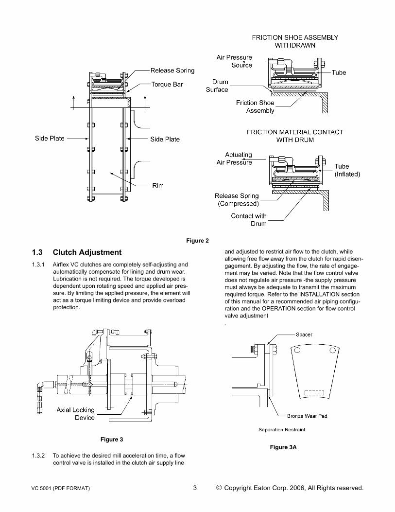
Figure 2
1.3 Clutch Adjustment1.3.1 Airflex VC clutches are completely self-adjusting and
automatically compensate for lining and drum wear. Lubrication is not required. The torque developed is dependent upon rotating speed and applied air pres-sure. By limiting the applied pressure, the element will act as a torque limiting device and provide overload protection.
Figure 3
1.3.2 To achieve the desired mill acceleration time, a flow control valve is installed in the clutch air supply line
and adjusted to restrict air flow to the clutch, while allowing free flow away from the clutch for rapid disen-gagement. By adjusting the flow, the rate of engage-ment may be varied. Note that the flow control valve does not regulate air pressure -the supply pressure must always be adequate to transmit the maximum required torque. Refer to the INSTALLATION section of this manual for a recommended air piping configu-ration and the OPERATION section for flow control valve adjustment.
Figure 3A
VC 5001 (PDF FORMAT) 3 © Copyright Eaton Corp. 2006, All Rights reserved.

2.0 INSTALLATION
Only qualified personnel should install, adjust or repair these units. Faulty workmanship will result in exposure to hazardous conditions or personal injury.
Do not inflate the element without having a drum in place. Inflation of the element without a drum in place will result in permanent dam-age to the element components.
2.1 Mounting Arrangements2.1.1 Airflex VC grinding mill clutch applications are avail-
able in single-narrow, single-wide, dual-narrow and dual-wide mounting configurations. See Figure 4. The clutch configuration is determined by the motor horse-power and RPM, the allowable motor overload (per cent rated horsepower) for mill starting, the inertia of the mill and the charge, and the physical space avail-able for the clutch. With the exception of single-narrow arrangements, all clutches can be supplied with axial locking devices.
2.2 Mounting Considerations2.2.1 Shaft alignment must be within the tolerances indi-
cated in the Alignment section of this manual.
Operation with shaft misalignment exceeding the limits indicated in this manual will result in accelerated wear of the clutch components.
2.2.2 The element must be protected from contamination from oil, grease or excessive amounts of dust.
Oil or grease contamination will result in a reduction of developed torque. Excessive dust contamination may result in incomplete disengagement. Either of these conditions will result in clutch slippage and overheating.
All rotating equipment must be guarded to comply with applicable safety standards.
Figure 4
2.2.3 All mounting fasteners must be of the proper size and grade, and torqued to the appropriate value. See Table 1.
Use only the proper grade and number of mounting fasteners. Using commercial grade fasteners (Grade 2) in place of Grade 8 fasten-ers (where called for) may result in failure under load, causing personal injury or equip-ment damage.
VC 5001 (PDF FORMAT) 4 © Copyright Eaton Corp. 2006, All Rights reserved.

TABLE 1FASTENER ASSEMBLY TORQUE
SN = SINGLE NARROW
SW = SINGLE WIDE
DN = DUAL NARROW
DW = DUAL WIDE
L = LUBED TORQUE - FT.-LB. (Nm) (30 WT. MOTOR OIL OR ANTI-SEIZE)
D = DRY TORQUE - FT.-LB. (Nm)
SIZE ELEMENT TO SPIDER/SIDE PLATE TO RIM TORQUE DRUM TO HUB TORQUE
SN 11.5VC500 3/8-16NC GR 2 D 15 (20) 1/2-13NC GR 2 D 38 (51)
SN14VC500 1/2-13NC GR 2 D 15 (20) 1/2-13NC GR 2 D 38 (51)
SN16VC600 1/2-13NC GR 2 D 38 (51) 3/4-10NC GR 2 L 93 (126)
SN20VC600 1/2-13NC GR 2 D 38 (51) 3/4-10NC GR 2 L 93 (126)
SN24VC650 5/8-11 NC GR 2 D 77 (104) 3/4-10NC GR 2 L 93 (126)
SN28VC650 5/8-11NC GR 2 D 77 (104) 3/4-10NC GR 2 L 93 (126)
SN33VC650 3/4-10 NC GR 2 L 93 (126) 3/4-10NC GR 2 L 93 (126)
SN37VC650 3/4-10NC GR 2 L 93 (126) 3/4-10NC GR 2 L 93 (126)
SN42VC650 3/4-10NC GR 2 L 93 (126) 3/4-10NC GR 2 L 93 (126)
DN 11.5VC500 3/8-16NC GR 2 D 15 (20) 1/2-13NC GR 8 D 109 (148)
DN14VC500 1/2-13NC GR 8 D 87 (118) 1/2-13NC GR 2 D 38 (51)
DN16VC600 1/2-13NC GR 2 D 38 (51) 3/4-10NC GR 8 L 245 (332)
DN20VC600 1/2-13NC GR 8 D 87 (118) 3/4-10NC GR 8 L 211 (286)
DN24VC650 5/8- 11 NC GR 2 D 77 (104) 3/4-10NV GR 2 L 93 (126)
DN28VC650 5/8- 11 NC GR 2 D 77 (104) 3/4-10NV GR 2 L 93 (126)
DN33VC650 3/4-10NC GR 2 L 93 (126) 3/4-10NC GR 2 L 93 (126)
DN37VC650 3/4-10NC GR 2 L 93 (126) 3/4-10NC GR 2 L 93 (126)
DN42VC650 3/4-10NC GR 2 L 93 (126) 3/4-10NC GR 2 L 93 (126)
SW 14VC1000 1/2-13NC GR 2 D 38 (51) 1/2- 13NC GR 8 L 109 (148)
SW 16VC1000 1/2-13NC GR 2 D 38 (51) 3/4-10NC GR 2 L 93 (126)
SW 20VC1000 1/2-13NC GR 2 D 38 (51) 3/4-10NC GR 2 L 93 (126)
SW24VC1000 5/8-11 NC GR 2 D 77 (104) 3/4- 10NC GR 2 L 93 (126)
SW28VC1000 5/8-11 NC GR 2 D 77 (104) 3/4-10NC GR 2 L 93 (126)
SW32VC1000 5/8-11 NC GR 2 D 77 (104) 3/4-10NC GR 2 L 93 (126)
SW38VC1200 3/4-10NC GR 2 L 93 (126) 3/4-10NC GR 2 L 93 (126)
VC 5001 (PDF FORMAT) 5 © Copyright Eaton Corp. 2006, All Rights reserved.

SIZE ELEMENT TO SPIDER/SIDE PLATE TO RIM TORQUE DRUM TO HUB TORQUE
SW42VC1200 3/4-10NC GR 2 L 93 (126) 3/4-10NC GR 2 L 93 (126)
SW46VC1200 7/8-9NC GR 2 L 109 (148) 1-8NC GR 2 L 163 (221)
SW52VC1200 7/8-9NC GR 2 L 109 (148) 1-8NC GR 2 L 163 (221)
SW51VC1600 7/8-9NC GR 2 L 109 (148) 1-8NC GR 2 L 163 (221)
SW60VC1600 1-8NC GR 2 L 163 (221) 1 1/2-6NC GR 2 L 566 (767)
SW66VC1600 1 1/4-7NC GR 2 L 325 (441) 1 1/2-6NC GR 2 L 566 (767)
DW 16VC1000 1/2-13NC GR 8 D 87 (118) 3/4-10NC GR 8 L 245 (332)
DW20VC1000 1/2-13NC GR 8 D 87 (118) 3/4- 10NC GR 8 L 245 (332)
DW24VC1000 5/8- 11 NC GR 8 D 174 (236) 3/4- 10NC GR 8 L 245 (332)
DW28VC1000 5/8- 11 NC GR 8 D 174 (236) 3/4- 10NC GR 8 L 245 (332)
DW32VC1000 5/8- 11NC GR 8 D 174 (236) 3/4- 10NC GR 8 L 245 (332)
DW38VC1200 3/4-10NC GR 8 L 245 (332) 3/4- 10NC GR 8 L 245 (332)
DW42VC1200 3/4-10NC GR 8 L 245 (332) 3/4- 10NC GR 8 L 245 (332)
DW46VC1200 7/8-9NC GR 2 L 109 (148) 1-8NC GR 8 L 510 (692)
DW52VC1200 7/8-9NC GR 2 L 109 (148) 1-8NC GR 8 L 510 (692)
DW51VC1600 7/8-9NC GR 2 L 163 (221) 1-8NC GR 8 L 510 (692)
DW60VC1600 1-8NC GR 2 L 190 (258) 1 1/2-6NC GR 2 L 650 (881)
DW66VC1600 1 1/4-7NC GR 2 L 380 (515) 1 1/2-6NC GR 2 L 650 (881)
DW76VC1600 1 1/4-7NC GR 2 L 380 (515) 1 1/2-6NC GR 2 L 650 (881)
HEX SIZES (in.)SIZE BOLT NUT SIZE BOLT NUT SIZE BOLT NUT
3/8NC 9/16 9/16 3/4NC 1-1/8 1-1/16 1-1/4NC 1-7/8 1-13/161/2NC 3/4 3/4 7/8NC 1-5/16 1-1/4 1-1/2NC 2-1/4 2-3/165/8NC 15/16 15/16 1NC 1-1/2 1-7/16
TABLE 1FASTENER ASSEMBLY TORQUE
SN = SINGLE NARROW
SW = SINGLE WIDE
DN = DUAL NARROW
DW = DUAL WIDE
L = LUBED TORQUE - FT.-LB. (Nm) (30 WT. MOTOR OIL OR ANTI-SEIZE)
D = DRY TORQUE - FT.-LB. (Nm)
VC 5001 (PDF FORMAT) 6 © Copyright Eaton Corp. 2006, All Rights reserved.

VC 5001 (PDF FORMAT) 7 © Copyright Eaton Corp. 2006, All Rights reserved.
2.3 Mounting Spider and Drum Hub2.3.1 The spider and drum hub are bored for a press fit onto
their respective shafts. The interference is approxi-mately 0.0005 in. per inch (.0005mm/mm) of shaft diameter.
2.3.2 Ensure the shaft is dean and free of nicks or burrs and check the shaft and bore diameters for proper fit. Tap the key into the keyway, making sure it bottoms, and apply a light coat of anti-seizing compound to the shaft and key.
2.3.3 Heat the drum hub or spider uniformly to 250°F (121°C) to expand the bore.
It is recommended the drum hub or spider be heated in oil or an oven; however, torches may be used. Use several with “rosebud” (broad-flame) tips and keep them moving to avoid "hot spots". Check bore temperature frequently to avoid overheating.
2.3.4 Slide the heated drum hub or spider onto the shaft. Hold in position and allow to cool.
2.4 Shaft AlignmentParallel Alignment Tolerance (Offset):Not to exceed 0.010 inch (.254mm) Total Indicator Reading (0.005 in. (.127mm) maximum offset).
Figure 5
TABLE 2“X” DIMENSIONS (FIG. 5)
SIZE “X” IN. (mm) SIZE “X” IN.
(mm) SIZE “X” IN. (mm) SIZE “X” IN.
(mm)
SN11.5VC500 6.750 (171.5) DN 11.5VC500 13.375 (339.7) SW14VC1000 11.875 (301.6) DW16VC1000 12.750 (323.9)
SN14VC500 6.812 (173.0) DN14VC500 13.438 (341.3) SW16VC1000 11.875 (301.6) DW20VC1000 12.750 (323.9)
SN16VC600 8.062 (204.8) DN16VC600 15.938 (404.8) SW20VC1000 11.875 (301.6) DW24VC1000 12.750 (323.9)
SN20VC600 8.062 (204.8) DN20VC600 15.938 (404.8) SW24VC1000 11.875 (301.6) DW28VC1000 12.750 (323.9)
SN24VC650 8.562 (217.5) DN24VC650 16.688 (423.9) SW28VC1000 11.875 (301.6) DW32VC1000 12.812 (325.4)
SN28VC650 8.562 (217.5) DN28VC650 16.688 (423.9) SW32VC1000 11.938 (303.2) DW38VC1200 15.000 (381.0)
SN33VC650 8.562 (217.5) DN33VC650 16.750 (425.5) SW38VC1200 14.125 (356.7) DW42VC1200 15.125 (384.2)
SN37VC650 8.562 (217.5) DN37VC650 16.750 (425.5) SW42VC1200 14.125 (358.7) DW46VC1200 15.250 (387.4)
SN42VC650 8.562 (217.5) DN42VC650 16.750 (425.5) SW46VC1200 14.125 (358.7) DW52VC1200 15.750 (400.0)
SW52VC1200 14.625 (371.5) DW51VC1600 20.000 (508.0)
SW51VC1600 18.875 (479.4) DW60VC1600 20.375 (517.5)
SW60VC1600 18.750 (476.31) DW66VC1600 22.000 (558.8)
SW66VC1600 20.500 (520.7) DW76VC1600 20.375 (517.5)

Angular Alignment Tolerance (Gap):Not to exceed 0.0005 inch per inch (0.0005 mm/mm) diameter at which readings are taken (“D” on Fig 5).Note : The alignment procedure described below hasbeen used successfully on many VC grinding millclutch applications. Other procedures, of course, maybe used; however, the alignment tolerances are thesame regardless of the technique used.
2.4.1 Foundations must be set so distance "X", shown on Figure 5 (or the appropriate drawing for non-standard applications), is established. If the clutch is mounted on a shaft haying plain bearings, make sure the shaft is centered within the bearings when establishing the "X" dimension. Refer to Table 2 for appropriate "X" dimensions.Note : It is presumed that one of the shafts has beenproperly located and anchored. When setting andaligning the grinding mill drive components, alwayswork from the pinion back to the motor.
2.4.2 Fabricate a rigid bracket for supporting a dial indicator and attach to the spider. See Figure 5
2.4.3 Thoroughly clean the flange O.D. and the face of the drum hub where alignment readings are to be taken.
2.4.4 Rotate the spider and take parallel alignment readings off the drum hub flange O.D. If both shafts can be rotated together, the alignment readings are less influ-enced by any surface irregularities.Note : On reverse-mounted clutches where only oneshaft can be rotated, the indicator is attached to thedrum hub and readings are taken off of the spider O.D.
When recording parallel alignment readings, “sag” of the indicator/indicator bracket must be accounted for.
2.4.5 Angular alignment readings can be made by accu-rately measuring the gap between the spider and drum hub faces with an inside micrometer. If a dial indicator is used, make sure to monitor and correct for any axial movement of the shaft To reduce the influ-ence any surface irregularities may have on the angu-lar alignment readings, index the spider 90 degrees after taking the initial set of readings. Take an addi-tional set of readings and index the spider another 90 degrees. Continue in this manner until four sets of readings have been taken. For misalignment correc-tion, use the average of the four readings at each position.
2.4.6 Shim and shift the base of the movable shaft to correct the misalignment After tightening the base, recheck the alignment and correct if necessary. Make sure to check for a “soft foot” condition. Dowel or chock into position after satisfactory alignment has been achieved.Note : On some applications, thermal growth of themill or gear reducer (if present) may result in unac-ceptable shaft alignment in a running condition. It isalways good practice to make a “hot alignment? checkand t-e-shim if necessary.
2.5 Axial Locking Device Adjustment2.5.1 If the "X" dimension shown on Table 2 could not be
achieved within +/- 0.250” (6.4mm), the axial locking device has a provision to accommodate this variation.
2.5.2 Position the motor shaft on its magnetic center and measure the gap between the faces of the drum hub and spider ("X" dimension on Table 2). The difference between this measured dimension and the value shown on Table 2 is the amount of correction to be made with adjustment of the axial locking device.
2.5.3 Referring to Figure 6, the overall length of the axial locking device can be adjusted by relocating shims (11,16) from one side of a bearing to another.
2.5.3.1 Remove four hex head screws and lock washers (6,7) from the bearing housing (8) and adapter plate (1 or 9).
2.5.3.2 Remove the snap ring (2) from the bearing housing.
2.5.3.3 After ensuring the shaft (3) is clean and free of foreign matter, nicks or burrs in the area between the two bearing housings, slide the bearing housing assembly toward the opposite bearing housing assembly to expose the bearing/spacer assembly (10,11,16).
VC 5001 (PDF FORMAT) 8 © Copyright Eaton Corp. 2006, All Rights reserved.

Figure 6
2.5.3.4 Remove the bearing locknut and lock washer (13,14) from the shaft.
2.5.3.5 The assembled length of the axial locking device is established by the location of the bearings with respect to the shaft. The assembled length can there-fore be adjusted by moving spacers from one side of the bearing to the other. Two thicknesses of spacers are included in each assembly (.025"(.6mm) and 0.098"(2.5mm)). After making the appropriate assem-bled length adjustment, reassemble, making sure the thinner spacers are against the bearing.
2.5.3.6 Tighten the locknut sufficiently to take up all axial clearance in the bearing/spacer/snap ring assembly.
2.5.3.7 Slide the housing back over the bearing and install the snap ring.
2.5.3.8 Secure and tighten the bearing housing to the adapter plate using four hex head screws and lockwashers. Tighten the screws to 35 ft.-lb. (47Nm).
2.5.3.9 After completing assembly, lubricate both bearings with No. 2 EP grease.
2.6 Installation of Element and Drum (Narrow, Dual Narrow and Single Wide)
2.6.1 Note the orientation of the drum flange with respect to the air connection(s) on the element and slide the drum into the element.
2.6.2 Attach the axial locking device (if required) to the drum flange with the appropriate screws and lockwashers. There are tapped holes in the drum flange to accept the screws.
2.6.3 Separate the shafts as far as the bearing clearances will allow and hoist the element/drum (axial locking device) into position. If an axial locking device is used, take special care when hoisting the element between the shafts. The axial locking device mounting plate binds easily against the spider face.
2.6.4 Attach the drum to the drum hub with the appropriate fasteners. See Table 1. Make sure the bore in the drum flange fully engages the pilot on the drum hub.
2.6.5 Install the air connection gaskets onto the air tubes. The metal backup washer is to be positioned toward the elbow (away from the spider). See Figure 7.Note : Some older elements use a flanged air connec-tion tube and a thin gasket See Table 3 for correct partnumbers.
Figure 7
VC 5001 (PDF FORMAT) 9 © Copyright Eaton Corp. 2006, All Rights reserved.

2.6.6 Align the element air connections with the passages in the spider and attach the element to the spider with the appropriate fasteners. See Table 1. Make sure the element fully engages the register in the spider.
2.6.7 Attach the axial locking device (ii required) mounting plate to the spider with the appropriate screws and lock washers. Rotate the motor shaft and push the spi-der toward the mill until the axial locking device mounting plate is flush against the spider face. Tighten the screws.
Do not attempt to pull the motor shaft back onto magnetic center by tightening the axial locking device mounting screws. To do so will damage the axial locking device.
2.7 Installation of Element and Drums (Dual Wide)
2.7.1 Separate the shafts as far as the bearing clearances will allow.
2.7.2 Attach the drum having the female register on the drum flange to the drum hub with short screws and lock washers. There are tapped holes in the drum flange to accept the screws. Make sure the bore in the drum flange fully engages the pilot on the drum hub. See Figure 4.
2.7.3 Disassemble the dual element into two halves and, noting the orientation of the air connections, place the element onto the drum installed in 2.7.2.
2.7.4 Noting the orientation of the flange on the remaining drum with respect to tie air connections on the remain-ing element, slide the drum into the element.
2.7.5 Attach the axial locking device (if required) to the flange of the remaining drum with the appropriate short screws and lock washers. There are tapped holes in the drum to accept the screws.
2.7.6 Hoist the element/drum (axial locking device) into position, align the tapped holes in the drum having the male pilot with the tapped holes in the drum attached to the drum hub, and attach both drums to the drum hub with the appropriate fasteners. See Table 1. Make sure the male pilot fully engages the female register. If an axial locking device is used, take special care when hoisting the element between the shafts. The axial locking device mounting plate binds easily against the spider face.
2.7.7 Align the air connections and reassemble the element halves, making sure the spacers are in place between the elements. See Figure 8.
2.7.8 Reassemble the air connection tubes. If an elbow has been removed, use a good quality pipe sealant on the threads. See Figure 8.Note : The elbow assemblies on the outboard element(farthest from the spider) use rubber compressionsleeves. Make sure the sleeves are securely on thelong air tubes.
2.7.9 Install the air connection gaskets onto the air tubes. The metal backup washer is to be positioned toward the elbow (away from the spider). See Figure 7.
2.7.10 Align the element air connections with the correspond-ing passages in the spider and attach the element to the spider with the appropriate fasteners. See Table 1. Make sure the element fully engages the register in the spider.
2.7.11 Attach the axial locking device (if required) mounting plate to the spider with the appropriate screws and lock washers. Rotate the motor shaft and push the spi-der toward the mill until the axial locking device mounting plate is flush against the spider face. Tighten the screws.
VC 5001 (PDF FORMAT) 10 © Copyright Eaton Corp. 2006, All Rights reserved.
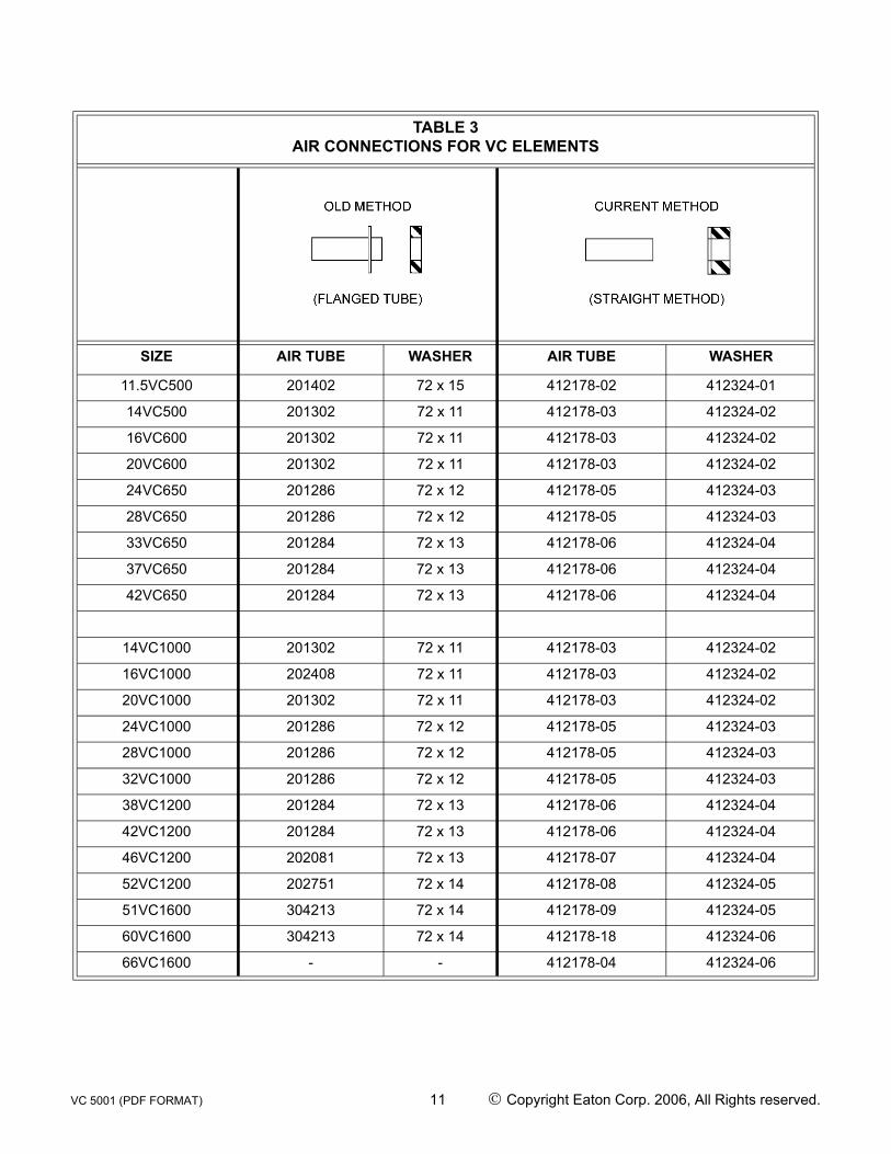
TABLE 3AIR CONNECTIONS FOR VC ELEMENTS
SIZE AIR TUBE WASHER AIR TUBE WASHER
11.5VC500 201402 72 x 15 412178-02 412324-01
14VC500 201302 72 x 11 412178-03 412324-02
16VC600 201302 72 x 11 412178-03 412324-02
20VC600 201302 72 x 11 412178-03 412324-02
24VC650 201286 72 x 12 412178-05 412324-03
28VC650 201286 72 x 12 412178-05 412324-03
33VC650 201284 72 x 13 412178-06 412324-04
37VC650 201284 72 x 13 412178-06 412324-04
42VC650 201284 72 x 13 412178-06 412324-04
14VC1000 201302 72 x 11 412178-03 412324-02
16VC1000 202408 72 x 11 412178-03 412324-02
20VC1000 201302 72 x 11 412178-03 412324-02
24VC1000 201286 72 x 12 412178-05 412324-03
28VC1000 201286 72 x 12 412178-05 412324-03
32VC1000 201286 72 x 12 412178-05 412324-03
38VC1200 201284 72 x 13 412178-06 412324-04
42VC1200 201284 72 x 13 412178-06 412324-04
46VC1200 202081 72 x 13 412178-07 412324-04
52VC1200 202751 72 x 14 412178-08 412324-05
51VC1600 304213 72 x 14 412178-09 412324-05
60VC1600 304213 72 x 14 412178-18 412324-06
66VC1600 - - 412178-04 412324-06
VC 5001 (PDF FORMAT) 11 © Copyright Eaton Corp. 2006, All Rights reserved.

.
Figure 8
Do not attempt to pull the motor shaft back onto magnetic center by tightening the axial locking device mounting screws. To do so will damage the axial locking device.
2.8 Air Control System2.8.1 A typical air control system is shown on Figure 9.
Since operating characteristics vary from one grinding mill to another, following are some general guidelines for installing the air controls.
2.8.1.1 The air receiver tank must be located as close to the rotors & as possible (the tank should be loacted within 15 feet of the solenoid valve, and solenoid valve should be within five feet from the rotoseal) for consis-tent clutch response. See Figure 10 for the appropri-ate air receiver tank size.
2.8.1.2 Use full size piping and valves consistent with the rotorseal size and keep the number of elbows to a minimum.
2.8.1.3 Use poppet-type solenoid valves. Spool valves are not recommended.
2.8.1.4 An air line lubricator is not required for the clutch ele-ment; however, if one is used, it must be a nonadjust-able, mist-type.
2.8.1.5 Make sure the flow control valve is installed with free flow (indicated by an arrow on the valve body) away from the clutch (free flow to exhaust).
2.8.1.6 The final connection to the rotorseal MUST be made with flexible hose and place no radial load upon the rotorseal. Also, if the rotorseal is mounted onto the end of a motor shaft, an insulating coupling must be installed between the piping and the rotorseal.
Do not use rigid pipe at the connection to the rotorseal. Rigid piping will result in excessive loads on the rotorseal bearings, shortening life.
2.9 Electrical Controls2.9.1 The basic Airflex grinding mill clutch control is shown
on Figure 11. This control provides run, inch and timed inch features only. Timed inch creates a delay between successive clutch engagements when spot-ting the mill to prevent clutch overheating and dam-age. Other control features, such as clutch slip detection, can be provided as required. Contact Airflex for details.
VC 5001 (PDF FORMAT) 12 © Copyright Eaton Corp. 2006, All Rights reserved.
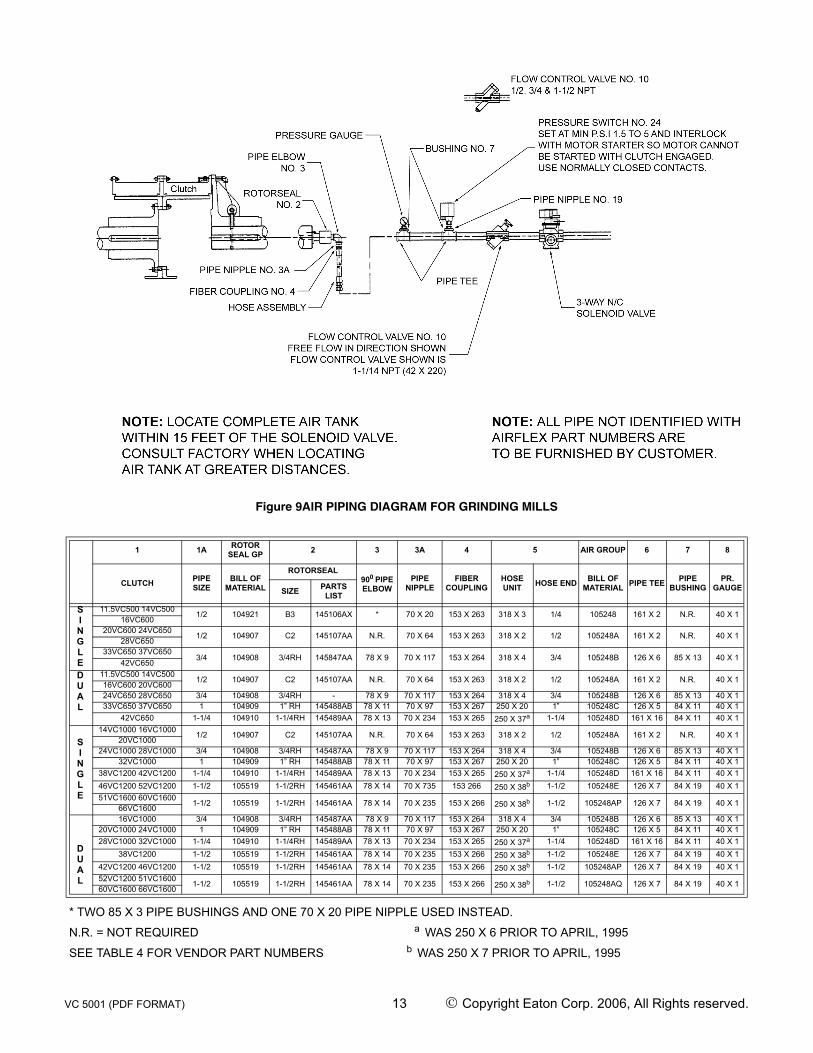
Figure 9AIR PIPING DIAGRAM FOR GRINDING MILLS
1 1A ROTOR SEAL GP 2 3 3A 4 5 AIR GROUP 6 7 8
CLUTCH PIPESIZE
BILL OFMATERIAL
ROTORSEAL900 PIPE ELBOW
PIPE NIPPLE
FIBER COUPLING
HOSE UNIT HOSE END BILL OF
MATERIAL PIPE TEE PIPE BUSHING
PR. GAUGESIZE PARTS
LIST
SINGLE
11.5VC500 14VC500 1/2 104921 B3 145106AX * 70 X 20 153 X 263 318 X 3 1/4 105248 161 X 2 N.R. 40 X 116VC600
20VC600 24VC6501/2 104907 C2 145107AA N.R. 70 X 64 153 X 263 318 X 2 1/2 105248A 161 X 2 N.R. 40 X 1
28VC65033VC650 37VC650
3/4 104908 3/4RH 145847AA 78 X 9 70 X 117 153 X 264 318 X 4 3/4 105248B 126 X 6 85 X 13 40 X 142VC650
DUAL
11.5VC500 14VC5001/2 104907 C2 145107AA N.R. 70 X 64 153 X 263 318 X 2 1/2 105248A 161 X 2 N.R. 40 X 1
16VC600 20VC60024VC650 28VC650 3/4 104908 3/4RH - 78 X 9 70 X 117 153 X 264 318 X 4 3/4 105248B 126 X 6 85 X 13 40 X 133VC650 37VC650 1 104909 1” RH 145488AB 78 X 11 70 X 97 153 X 267 250 X 20 1” 105248C 126 X 5 84 X 11 40 X 1
42VC650 1-1/4 104910 1-1/4RH 145489AA 78 X 13 70 X 234 153 X 265 250 X 37a 1-1/4 105248D 161 X 16 84 X 11 40 X 1
SINGLE
14VC1000 16VC1000 1/2 104907 C2 145107AA N.R. 70 X 64 153 X 263 318 X 2 1/2 105248A 161 X 2 N.R. 40 X 120VC1000
24VC1000 28VC1000 3/4 104908 3/4RH 145487AA 78 X 9 70 X 117 153 X 264 318 X 4 3/4 105248B 126 X 6 85 X 13 40 X 132VC1000 1 104909 1” RH 145488AB 78 X 11 70 X 97 153 X 267 250 X 20 1” 105248C 126 X 5 84 X 11 40 X 1
38VC1200 42VC1200 1-1/4 104910 1-1/4RH 145489AA 78 X 13 70 X 234 153 X 265 250 X 37a 1-1/4 105248D 161 X 16 84 X 11 40 X 146VC1200 52VC1200 1-1/2 105519 1-1/2RH 145461AA 78 X 14 70 X 735 153 266 250 X 38b 1-1/2 105248E 126 X 7 84 X 19 40 X 151VC1600 60VC1600
1-1/2 105519 1-1/2RH 145461AA 78 X 14 70 X 235 153 X 266 250 X 38b 1-1/2 105248AP 126 X 7 84 X 19 40 X 166VC1600
DUAL
16VC1000 3/4 104908 3/4RH 145487AA 78 X 9 70 X 117 153 X 264 318 X 4 3/4 105248B 126 X 6 85 X 13 40 X 120VC1000 24VC1000 1 104909 1” RH 145488AB 78 X 11 70 X 97 153 X 267 250 X 20 1” 105248C 126 X 5 84 X 11 40 X 128VC1000 32VC1000 1-1/4 104910 1-1/4RH 145489AA 78 X 13 70 X 234 153 X 265 250 X 37a 1-1/4 105248D 161 X 16 84 X 11 40 X 1
38VC1200 1-1/2 105519 1-1/2RH 145461AA 78 X 14 70 X 235 153 X 266 250 X 38b 1-1/2 105248E 126 X 7 84 X 19 40 X 142VC1200 46VC1200 1-1/2 105519 1-1/2RH 145461AA 78 X 14 70 X 235 153 X 266 250 X 38b 1-1/2 105248AP 126 X 7 84 X 19 40 X 152VC1200 51VC1600
1-1/2 105519 1-1/2RH 145461AA 78 X 14 70 X 235 153 X 266 250 X 38b 1-1/2 105248AQ 126 X 7 84 X 19 40 X 160VC1600 66VC1600
* TWO 85 X 3 PIPE BUSHINGS AND ONE 70 X 20 PIPE NIPPLE USED INSTEAD.
N.R. = NOT REQUIRED a WAS 250 X 6 PRIOR TO APRIL, 1995
SEE TABLE 4 FOR VENDOR PART NUMBERS b WAS 250 X 7 PRIOR TO APRIL, 1995
VC 5001 (PDF FORMAT) 13 © Copyright Eaton Corp. 2006, All Rights reserved.

+ REQUIRES REDUCING BUSHING 85 X 4N.R. = NOT REQUIRED
Figure 9 : AIR PIPING DIAGRAM FOR GRINDING MILLS
9 10 11 12 13 14 15 16 17 18 19 20 21 22 23 24
PRESSURE SWITCH
FLOW CONTROL
VALVE
SOLENOID VALVE AIR FILTER PRESSURE
REGULATORPIPE
NIPPLECHECK VALVE
PIPE BUSHING AIR TANK PIPE
BUSHING PIPE NIPPLE DRAIN VALVE
RELIEF VALVE PIPE TEE PIPE
BUSHINGPRESSURE
SWITCH
219206-28 42 X 223 63 X 368 364 X 1 365 X 2 70 X 169 42 X 243 85 X 4 156 X 4 85 X 13 70 X 205 42 X 79 153 X 705 126 X 2 85 X 4 219206-27
219206-28 42 X 223 63 X 368 364 X 1 365 X 2 70 X 169 42 X 243 84 X 7 156 X 2 85 X 13 70 X 205 42 X 79 153 X 705 126 X 2 84 x 7 219206-27
219206-28 42 X 224 63 X 438 364 X 2 365 X 3 70 X 203 42 X 244 84 X 10 156 X 2 85 X 13 70 X 205 42 X 79 153 X 705 126 X 2 84 x 10 219206-27
219206-28 42 X 223 63 X 368 364 X 1 365 X 2 70 X 169 42 X 243 84 X 7 156 X 2 85 X 13 70 X 205 42 X 79 153 X 705 126 X 2 84 x 7 219206-27
219206-28 42 X 224 63 X 438 364 X 2 365 X 3 70 X 203 42 X 244 84 X 10 156 X 2 85 X 13 70 X 205 42 X 79 153 X 705 126 X 2 84 x 10 219206-27
219206-28 42 X 215 63 X 439 364 X 3 365 X 4 70 X 204 42 X 245 84 X 12 156 X 5 85 X 13 70 X 205 42 X 79 153 X 705 126 X 2 84 x 12 219206-27
219206-28 42 X 220 63 X 440 364 X 3 365 X 4 70 X 204 42 X 245 84 X 14 156 X 5 85 X 13 70 X 205 42 X 79 153 X 705 126 X 2 84 x 12 219206-27
219206-28 42 X 231 63 X 441 364 X 3 365 X 4 70 X 204 42 X 245 84 X 20 156 X 5 85 X 13 70 X 205 42 X 79 153 X 705 126 X 2 84 x 12 219206-27
219206-28 42 X 231 63 X 441 364 X 3 365 X 4 70 X 204 42 X 245 84 X 20 156 X 11 84 X 21 70 X 205 42 X 79+ 153 X 705 N.R. N.R. 219206-27
219206-28 42 X 231 63 X 441 364 X 3 365 X 4 70 X 204 42 X 245 84 X 20 156 X 12 84 X 21 70 X 205 42 X 79+ 153 X 705 N.R. N.R. 219206-27
VC 5001 (PDF FORMAT) 14 © Copyright Eaton Corp. 2006, All Rights reserved.

Figure 10 AIR TANK (ITEM NO.17)
N/A = Not Applicable
NOTE: Tanks are constructed in accordance the Unfired Pressure Vessels Section VIIIof the ASME Code. Maximum working pressure 125 PSI.
On special order, tanks can be constructed to comply with the requirements of anyregulatory body.
Airflex Part No.
Dimensions (Inches) National Pipe Tap Volume
A B C D E F G H J K ft.3 Gallon
156 x 2 38 N/A 10 19 16 2 3/4 N/A 2 1/2 4 30
156 x 4 24 N/A 6 12 10 3/4 3/4 N/A 3/4 1/2 1 8
156 x 5 48 N/A 12 24 20 2 3/4 N/A 2 1/2 8 60
156 x 11 70 35 10 10 24 2 2 2 1 3/4 18 135
156 x 12 84 42 11-1/2 11-1/2 30 2 2 2 1 3/4 34 255
VC 5001 (PDF FORMAT) 15 © Copyright Eaton Corp. 2006, All Rights reserved.

TABLE 4AIRFLEX/VENDOR COMPONENT CROSS REFERENCE (CONTINUED)
ITEM NO. DESCRIPTION VENDOR VENDOR PART NO. AIRFLEX
PART NO.
4 FIBER COUPLING O.Z.GEDNEY
I.C.C. 50 153 X 263
I.C.C. 75 153 X 264
I.C.C. 125 153 X 265
I.C.C. 150 153 X 266
I.C.C. 100 153 X 267
5 HOSE STRATOFLEX INC.
211R10-PM20-AS20-16 + 1016-20-20B 250 X 6
21 1R24-PM-AS24-15 1/8 + 1016-2424B 250 X 7
211R16-PM16-JS16-15 1/2 + 1015-16-16S 250 X 20
211 R10-PM20-AS20-24 + 1016-20-20B 250 X 37
211 R24-PM-AS24-30 + 1016-24-24B 250 X 38
223R10-PM8-AS10-12 + 1014-8-10 318 X 2
223R8-PM6-AS8-12 + 1014-6-8 318 X 3
223R12-PM12-ASl2-15 + 1014-12-12 318 X 4
8 PRESSURE GAUGE C.A. NORGREN CO. 18-013-085-S 40 X 1
9 PRESSURE SWITCH SQUARE “D” CO. 9012 GAW-5-K1 219206-28
10 FLOW CONTROL VALVE
ROSS OPERATING VALVE CO. 1968A7007 42 X 220
WABCO/AMERICAN STAN-DARD
P-54986 42 X 215
P-53010-2 42 X 223
P-5501 0 42 X 224
SCHRADER BELLOWS DIV. 3250-1 500 42 X 231
11 SOLENOID VALVE SCHRADER BELLOWS DIV.
N355-41-048-53 63 X 368
N355-61-048-53 63 X 438
N365-71-048-53 63 X 439
N365-81-048-53 63 X 440
N365-91-048-53 63 X 441
12 AIR FILTER C.A. NORGREN CO.
F12-4OO-M3PA 364 X 1
F17-600-M3DA 364 X 2
F17-800-M3DA 364 X 3
13 PRESSURE REGULA-TOR C.A. NORGREN CO.
R12-401-RGLA-S 365 X 2
R17-601-RGLA-S 365 X 3
R17-801-RGLA-S 365 X 4
15 CHECK VALVE TELEDYNE REPUBLIC MFG.
483-1/2-B-1-1 42 X 243
483-3/4-B-1-1 42 X 244
483-1-B-1-1 42 X 245
20 DRAIN VALVE ESSEX BRASS #15 42 X 79
21 RELIEF VALVE FC KINGSTON CO. FIG. 112Cx 1/4AT 125 153 X 705
24 PRESSURE SWITCH SQUARE “D” CO. 9012 GAW-4-K1 219206-27
VC 5001 (PDF FORMAT) 16 © Copyright Eaton Corp. 2006, All Rights reserved.

Figure 11 WIRING DIAGRAM FOR GRINDING MILL CONTROL PANEL REF.: LA-9811
VC 5001 (PDF FORMAT) 17 © Copyright Eaton Corp. 2006, All Rights reserved.
3.0 OPERATION
Exceeding the operating limits described in this section may result in personal injury or equipment damage.
3.1 Torque, RPM and Pressure Limits3.1.1 The developed torque is directly proportional to the
applied air pressure. If the developed torque seems inadequate, check for oil, grease or dust contamina-tion.
Maximum applied air pressure is 125 psig (8.5 bar). Operation at pressures exceeding 125 psig may result in damage to the clutch ele-ment Airflex grinding mill clutches typically require only 100 psig (6.8 bar) operating pres-sure.
The non-asbestos friction material used in Airflex VC units may not develop rated torque initially, as a short Wear-in” period is required. It is very important that the first few mill starts be monitored to prevent excessive heat generated from slippage.
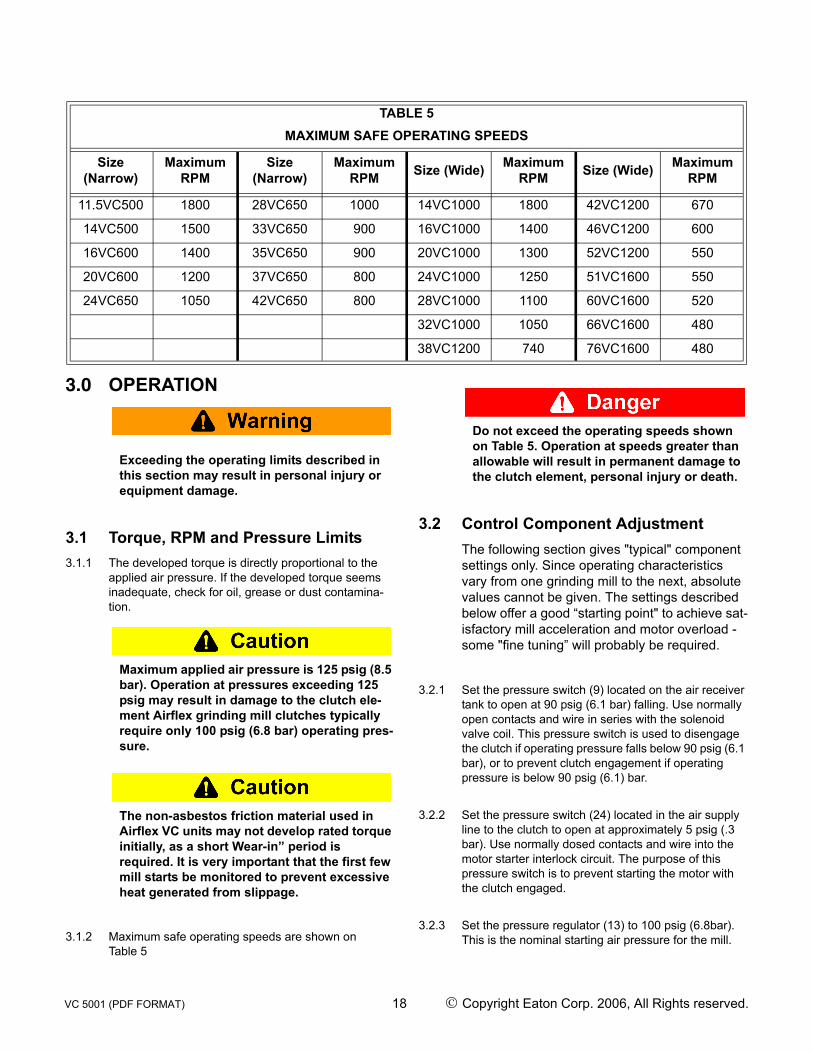
3.1.2 Maximum safe operating speeds are shown on Table 5
Do not exceed the operating speeds shown on Table 5. Operation at speeds greater than allowable will result in permanent damage to the clutch element, personal injury or death.
3.2 Control Component AdjustmentThe following section gives "typical" component settings only. Since operating characteristics vary from one grinding mill to the next, absolute values cannot be given. The settings described below offer a good “starting point" to achieve sat-isfactory mill acceleration and motor overload - some "fine tuning” will probably be required.
3.2.1 Set the pressure switch (9) located on the air receiver tank to open at 90 psig (6.1 bar) falling. Use normally open contacts and wire in series with the solenoid valve coil. This pressure switch is used to disengage the clutch if operating pressure falls below 90 psig (6.1 bar), or to prevent clutch engagement if operating pressure is below 90 psig (6.1) bar.
3.2.2 Set the pressure switch (24) located in the air supply line to the clutch to open at approximately 5 psig (.3 bar). Use normally dosed contacts and wire into the motor starter interlock circuit. The purpose of this pressure switch is to prevent starting the motor with the clutch engaged.
3.2.3 Set the pressure regulator (13) to 100 psig (6.8bar). This is the nominal starting air pressure for the mill.
TABLE 5MAXIMUM SAFE OPERATING SPEEDS
Size (Narrow)
Maximum RPM
Size (Narrow)
Maximum RPM Size (Wide) Maximum
RPM Size (Wide) Maximum RPM
11.5VC500 1800 28VC650 1000 14VC1000 1800 42VC1200 670
14VC500 1500 33VC650 900 16VC1000 1400 46VC1200 600
16VC600 1400 35VC650 900 20VC1000 1300 52VC1200 550
20VC600 1200 37VC650 800 24VC1000 1250 51VC1600 550
24VC650 1050 42VC650 800 28VC1000 1100 60VC1600 520
32VC1000 1050 66VC1600 480
38VC1200 740 76VC1600 480
VC 5001 (PDF FORMAT) 18 © Copyright Eaton Corp. 2006, All Rights reserved.

3.2.4 With the motor "off", manually trip the solenoid valve and note the time elapsed for the pressure gauge (8) to register full tank pressure.
3.2.5 Repeat the above procedure while adjusting the flow control valve (10) to supply a pressure rate of approxi-mately 20 psig/sec. (1.4 bar/sec.). Due to the non-lin-earity of the pressure-time curve (See Figure 12), it will be easier to use a reduced value to set the flow control valve. For example, if the tank pressure is 100 psig (6.8 bar), to obtain a flow rate of 20 psig/sec. (1.4 bar/sec.), time the pressure build up to 80 psig (5.4 bar) and adjust the flow control valve to deliver this pressure in 4 seconds, which, for all practical pur-poses, would equate to the desired 20 psig/sec. (1.4 bar/sec.).
Figure 12
3.2.5.1 The flow rate is increased by turning the flow control valve adjusting screw clockwise on the 3/4”, 1” and 1 -1/4” valves, and counter-clockwise on the 1-1/2” valve. The 1-1/2” valve has wrench fiats on the adjusting screw. The 1-1/4” valve has a knurled adjusting knob. The 3/4” and 1" valves have slotted adjusting screws.
3.2.6 Manually engage the clutch several times to verify the flow control valve setting. Also, confirm operation of the pressure switches at this time.
3.2.7 Check all other interlocks that affect the starting of the mill and remove any jumpers that may have been installed.
The flow rate described typically will result in a 4-7 second mill acceleration time (timed from the instant the clutch shoes make con-tact with the drum to the instant the clutch locks up); however, since operating charac-teristics vary from mill to mill, the mill acceler-
ation at the above flow setting may be greater or less than the allow able 4-7 second range.
The non-asbestos friction material used on Airflex VC clutches may not develop rated torque initially, as a short ‘wear-in” period is required. It is very important that the first few mill starts be monitored closely to prevent damage to the clutch components.
3.2.8 Start the motor and engage the clutch, noting the mill acceleration time. ABORT THE START IF THE CLUTCH SLIPS FOR MORE THAN SEVEN SEC-ONDS!
3.2.9 Disengage the clutch (if the start has not been aborted) and allow the drum(s) to cool to room tem-perature. Make the appropriate adjustment to the flow control valve if the mill acceleration fell outside of the 4-7 second range and retry. Repeat until the desired acceleration time has been achieved.Note : If the motor overload is beyond allowable limitsduring the start (typically the result of too high operat-ing pressure), reduce the operating pressure andincrease the flow rate. If the motor is sized correctlyfor the mill load conditions, the overload on the motoris directly proportional to the applied air pressure - notthe flow rate.
VC 5001 (PDF FORMAT) 19 © Copyright Eaton Corp. 2006, All Rights reserved.

4.0 MAINTENANCE
Only qualified personnel should maintain and repair these units. Faulty workmanship may result in personal injury or equipment dam-age.
When replacing clutch components, use only genuine, Airflex replacement parts. Use of replacement material which is not of Airflex origin till void all warranties.
4.1 Periodic Inspection4.1.1 The following items may be inspected without disas-
sembly of the clutch:
4.1.1.1 Friction Shoe Assembly Lining Wear - Check the lining thickness and compare to the valves shown on Table 6. If the linings have worn to minimum allowable thickness or less, they must be replaced as a com-plete set.
Operation with friction material worn to less than minimum allowable thickness till result in damage to the drum.
Note : A wear indicating groove (see figure in previ-ous page) is provided on each end of the friction block. The maximum wear point, which coincides with the values shown on Table 6, is at the bottom of the groove.
4.1.1.2 Contamination of Shoes or Drum - Oil or grease contamination will reduce the developed torque of the clutch. Disassembly will be required to clean any oil or grease buildup. In extremely dusty environments, dust may accumulate in the backing plate cavities to the point where the friction shoes will not properly retract Dust accumulations may be vacuumed out of the cavi-ties.
Do not attempt to use a solvent to remove oil or grease without first removing the element While squirting a solvent into an installed clutch may improve performance temporarily, a fire hazard exists from the heat generated during slippage.
Do not use compressed air to blow dust accu-mulations out of the backing plates. Although the friction material does not contain asbes-tos, the dust created as the friction material wears, along with the dust from the operating environment, may irritate the respiratory sys-tem.
4.1.1.3 Air Control Components-Check for proper adjust-ment of the air control components. Make sure the safety pressure switches are set correctly. Repair any air leaks as discovered.
4.1.2 Partial or complete disassembly is required to inspect the following items:
4.1.2.1 Drum Diameter Wear - Check the O.D. of the drum and compare to the values shown on Table 7. Minor heat-checking may be removed by machining the drum O.D. If the drum has been subjected to exces-sive heat, the open end may flare out, giving the impression that the drum has not worn. It is therefore important to check the diameter at several locations across the face.
Table 6Friction Material Thickness
NARROW SERIES
Element Size
Min. Allowable Lining
Thickness, in.(mm)
Original Lining Thickness,
in.(mm)
11.5VC500 thru 20VC600 .15 (3,8) .33 (8,4)
24VC650 thru 28VC650 .15 (3,8) .45 (11,4)
33VC650 thru 42VC650 .28 (7,1) .58 (14,7)
WIDE SERIES14VC1000 thru
20VC1000 .15 (3,8) .33 (8,4)
24VC1000 thru 28VC1000 .15 (3,8) .45 (11,4)
32VC1000 thru 42VC1200 .38 (9,5) .58 (14,7)
46VC1200 thru 52VC1200 .38 (9,5) .69 (17,5)
51 thru 76 VC1600 .30 (7,6) .67 (17,0)
VC 5001 (PDF FORMAT) 20 © Copyright Eaton Corp. 2006, All Rights reserved.

Operation of the clutch on a drum that has worn, or has been machined, to less that min-imum allowable diameter will result in dam-age to the element components.
4.1.2.2 Air Actuating Tube - Check that the tube has not been damaged by excessive heat. If any portion of the tube is hard or charred, the tube must be replaced. Check for any blisters, which would indicate ply sepa-ration. A tube in this condition must also be replaced.
4.1.2.3 Friction Shoe Lining Wear - If the linings are glazed, they may be lightly sanded to remove the glazing PROVlDlNG THEY DO NOT CONTAlN ASBESTOS.
Clean the edge of the lining and note the pres-ence of a blue stripe and a white stripe along with brass flakes in the friction material. If the above exists, the linings contain asbestos Using the appropriate precautions for work-ing with asbestos, remove the linings and dis-pose of properly. DO NOT ATTEMPT TO SAND FRICTION MATERIAL CONTAINING ASBES-TOS.
When working with any friction material, regardless of whether or not it contains asbestos, always wear approved safety equipment
4.1.2.4 Uneven Friction Lining Wear-Tapered wear across the friction surface typically indicates a worn drum and/or misalignment. If two or more adjacent shoes are worn on one end only, the air actuating tube has most likely developed a ply separation at that location.
4.1.2.5 Backing Plate Wear - Wear on the ends of the back-ing plates from bearing against the side plates is indic-ative of misalignment or thrusting. If wear is on one end only, and uniform for all backing plates, a worn drum may be causing the shoes to thrust as the ele-ment engages. If wear exists on both ends of all of the backing plates, excessive misalignment is probably the cause. Slight notching in the torque bar cavity is normal; however, if the notching occurs in a short amount of time, check shaft alignment If both wails in the torque bar cavity are notched, there may be a sig-nificant vibration (torsional) problem.
.
* Note: The number preceding the letters “VC” in the element size designates the original drum diameter in inches.Example: 16VC600 - Original drum diameter = 16.00 inches (406mm).Minimum allowable drum diameter is:16(406) - 0.09(2) = 15.91(404).
4.1.2.6 Release Springs and Torque Bars - Excessive wear at the ends of the torque bars where the release springs make contact indicates excessive parallel mis-alignment.
4.1.2.7 Side Plates -Any wear on the backing plates will also be reflected as elongation of the torque bar holes in the side plates.
4.1.2.8 Contamination of Friction Shoes - Mild oil or grease contamination may be removed with a solvent Linings which have become saturated must be replaced. Also, linings that have been charred from excessive heat must be replaced.
When using any solvent, always follow the appropriate safety precautions.
Table 7Drum Wear Limits
NARROW SERIES
Element Size Max. Allowable wear on Drum Diameter* in.(mm)
11.5VC500 thru 16VC600 .09 (2)20VC600 thru 24VC650 .12 (3)
28VC650 .19 (5)33VC656 thru 42VC650 .19 (5)
WIDE SERIES14VC1000 thru
16VC1000 .09 (2)
20VC1000 thru 24VC1000 .13 (3)
28VC1000 .19 (5)32VC1000 thru
38VC1200 .19 (5)
42VC1200 thru 46VC1200 .25 (6)
52VC1600 thru 76VC1600 .25 (6)
VC 5001 (PDF FORMAT) 21 © Copyright Eaton Corp. 2006, All Rights reserved.

4.1.2.9 Excessive Dust Accumulation - if dust becomes packed in the backing plate cavities, a pressurized enclosure should be considered. Excessive accumula-tions will prevent complete shoe retraction.
4.2 Removal of Element Assembly and Drum (Narrow, Dual Narrow and Sin-gle Wide)
Prior to removal of the clutch, make sure the mill is in, and will remain in, a safe condition.
4.2.1 Match mark the element to the spider and the drum to the drum hub.
4.2.2 Disconnect the element from the spider and allow it to rest on the drum.
4.2.3 Disconnect the axial locking device (ii used) from the spider and separate the shafts as far as the bearings will allow.
4.2.4 Connect an overhead support to the element and apply enough tension to support the weight of the ele-ment and drum.
4.2.5 Remove the fasteners attaching the drum to the drum hub and hoist the element/drum out from between the shafts. If an axial locking device is used, take special care when hoisting the element/drum from between the shafts, as the axial locking device mounting plate binds easily against the spider face.
Use extreme care when disconnecting the drum from the hub. Shear points exist at the mounting holes.
4.3 Removal of Element Assemblies and Drums (Dual Wide)
4.3.1 Match mark the element assemblies to each other and to the spider. Also, match mark the drums to each other and to the drum hub.
4.3.2 Disconnect the dual element from the spider and allow it to rest on the drums. Remove the air connection tubes.
4.3.3 Remove the fasteners and spacers attaching the ele-ment halves together.
4.3.4 Disconnect the axial locking device (if used) from the spider and separate the shafts as far as the bearings will allow.
4.3.5 Attach an overhead support to the spider-side ele-ment and apply enough tension to support the weight of the element half and one of the drums.
4.3.6 Remove the through bolts and nuts attaching the drums to the drum hub. DO NOT REMOVE THE SHORT SCREWS AND LOCKWASHERS WHICH HOLD THE FEMALE DRUM ONTO THE DRUM HUB. Carefully hoist the spider-side element and drum out from between the shafts. If an axial locking device is used, take special care when hoisting the element/drum from between the shafts, as the axial locking device mounting plate binds easily against the face of the spider.
4.3.7 Attach an overhead support to the remaining element and apply enough tension to support the weight of the element and drum.
4.3.8 Remove the short screws and lock washers holding the drum onto the drum hub and carefully hoist the element and drum out from between the shafts.
Use extreme care when disconnecting the drums from the drum hub. Shear points exist at the mounting holes.
4.4 Removal of Spider and Drum Hub4.4.1 Puller holes are provided for removal. It will usually
require heating along with the puller. When heating, heat uniformly to prevent hot spots.
4.5 Disassembly of the Element4.5.1 Lay the element flat on a clean work surface.
4.5.2 Remove the side plate and clean for reassembly. If the torque bar holes are elongated more than one-half the diameter of the pin on the end of the torque bar, the side plate must be replaced.
4.5.3 Remove the friction shoe assemblies, torque bars and release springs. If the torque bars and springs come out of the element with the friction shoe assemblies, carefully tap them out of the backing plate cavities. Note wear and replace as necessary.
VC 5001 (PDF FORMAT) 22 © Copyright Eaton Corp. 2006, All Rights reserved.
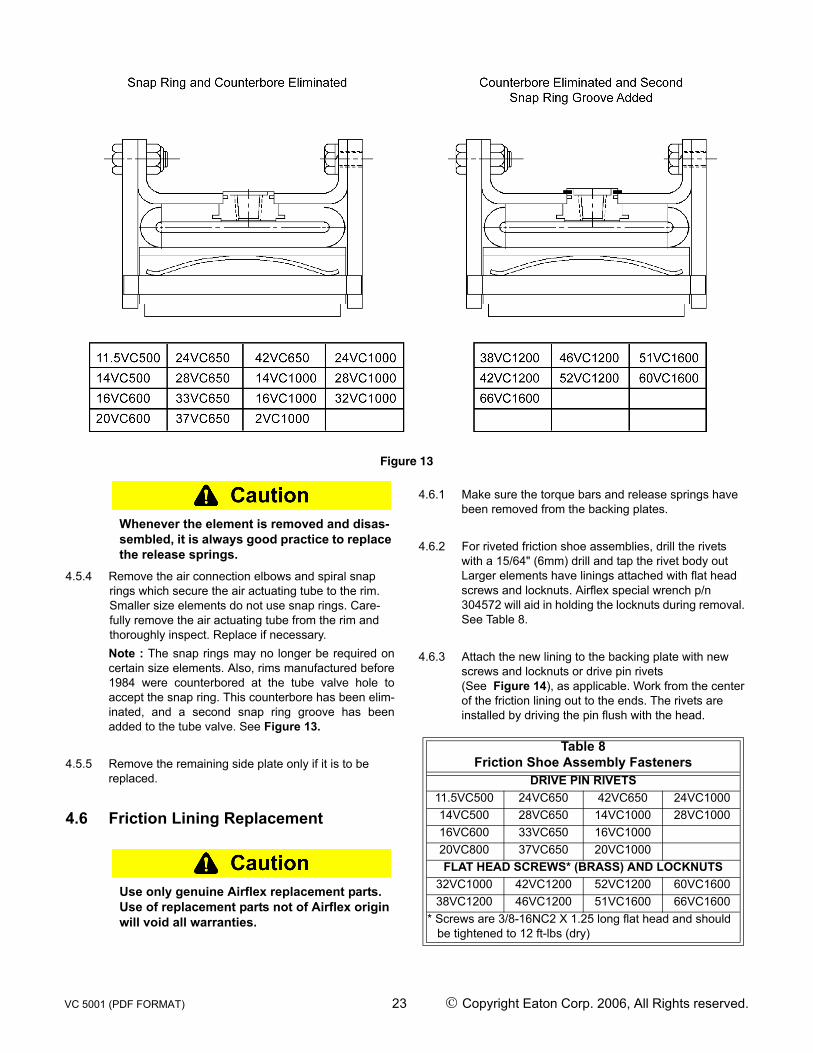
Figure 13
Whenever the element is removed and disas-sembled, it is always good practice to replace the release springs.
4.5.4 Remove the air connection elbows and spiral snap rings which secure the air actuating tube to the rim. Smaller size elements do not use snap rings. Care-fully remove the air actuating tube from the rim and thoroughly inspect. Replace if necessary.Note : The snap rings may no longer be required oncertain size elements. Also, rims manufactured before1984 were counterbored at the tube valve hole toaccept the snap ring. This counterbore has been elim-inated, and a second snap ring groove has beenadded to the tube valve. See Figure 13.
4.5.5 Remove the remaining side plate only if it is to be replaced.
4.6 Friction Lining Replacement
Use only genuine Airflex replacement parts. Use of replacement parts not of Airflex origin will void all warranties.
4.6.1 Make sure the torque bars and release springs have been removed from the backing plates.
4.6.2 For riveted friction shoe assemblies, drill the rivets with a 15/64" (6mm) drill and tap the rivet body out Larger elements have linings attached with flat head screws and locknuts. Airflex special wrench p/n 304572 will aid in holding the locknuts during removal. See Table 8.
4.6.3 Attach the new lining to the backing plate with new screws and locknuts or drive pin rivets (See Figure 14), as applicable. Work from the center of the friction lining out to the ends. The rivets are installed by driving the pin flush with the head.
Table 8Friction Shoe Assembly Fasteners
DRIVE PIN RIVETS11.5VC500 24VC650 42VC650 24VC100014VC500 28VC650 14VC1000 28VC100016VC600 33VC650 16VC100020VC800 37VC650 20VC1000FLAT HEAD SCREWS* (BRASS) AND LOCKNUTS
32VC1000 42VC1200 52VC1200 60VC160038VC1200 46VC1200 51VC1600 66VC1600
* Screws are 3/8-16NC2 X 1.25 long flat head and should be tightened to 12 ft-lbs (dry)
VC 5001 (PDF FORMAT) 23 © Copyright Eaton Corp. 2006, All Rights reserved.

Figure 14
4.7 Assembly of the Element4.7.1 Make sure all of the components have been cleaned
and any damaged or worn components have been repaired or replaced.
4.7.2 Assemble one of the side plates to the rim with cap screws and lockwashers. It is not necessary to install through bolts and locknuts at this time.
4.7.3 Lay the rim/side plate assembly on a dean, Rat work surface, side plate down.
4.7.4 Carefully insert the air actuating tube into the rim. Push the valves on the tube through the correspond-ing holes in the rim and install the spiral snap rings (ii applicable).
4.7.5 Place a torque bar in each mating hole in the side plate, slide a friction shoe assembly onto each torque bar and carefully tap a release spring (51VC1600, 60VC1600 and 66VC1600 elements have two release springs in each cavity) into place. Make sure the spring is positioned on the side of the torque bar oppo-site the friction lining. Also, the spring must contact the torque bar at two points, not one. See Figure 15.
4.7.6 Lay the remaining side plate in position so the air con-nections and torque bar. holes are properly aligned.
4.7.7 Carefully guide the torque bars into the corresponding holes in the side plate. It is often helpful to install four equally spaced screws and nuts through the rim and side plate to keep some tension on the side plate throughout this step.
4.7.8 Attach the side plate to the rim with cap screws and lock washers, making sure all of the torque bars are seated in their side plate holes.
4.7.9 Note the orientation of the air connections and install the through bolts and locknuts where applicable.
4.7.10 Reinstall the elbows using a good quality sealant on the pipe threads. Install the air connections on single narrow, dual narrow and single wide elements. Install only the short air connections (element closest to spi-der) on dual wide elements.
4.7.11 Reinstall per 2.0.
5.0 SPARE PARTS STORAGE
5.1 Element Assemblies5.1.1 Element assemblies must always be stored flat Stor-
age in the standing position may cause the rims to go out-of-round.
5.2 Drums5.2.1 Drums must be stored open end down. Similar to ele-
ment assemblies, storage of a drum in the standing position will adversely affect roundness.
5.3 Air Actuating Tubes5.3.1 Air actuating tubes are shipped from the Airflex plant
folded to conserve. shipping space. Upon receipt, remove the tube from its container and allow it to assume its natural shape. Store in a cool, dry area, away from electrical equipment and ultraviolet light.
Figure 15
VC 5001 (PDF FORMAT) 24 © Copyright Eaton Corp. 2006, All Rights reserved.
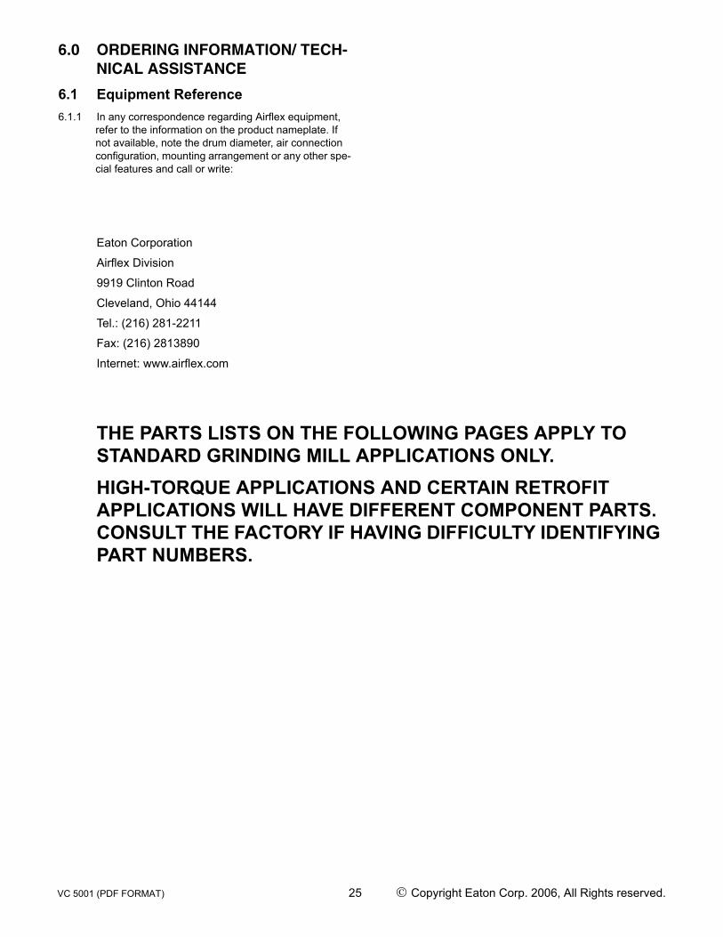
6.0 ORDERING INFORMATION/ TECH-NICAL ASSISTANCE
6.1 Equipment Reference6.1.1 In any correspondence regarding Airflex equipment,
refer to the information on the product nameplate. If not available, note the drum diameter, air connection configuration, mounting arrangement or any other spe-cial features and call or write:
Eaton Corporation
Airflex Division
9919 Clinton Road
Cleveland, Ohio 44144
Tel.: (216) 281-2211
Fax: (216) 2813890
Internet: www.airflex.com
THE PARTS LISTS ON THE FOLLOWING PAGES APPLY TO STANDARD GRINDING MILL APPLICATIONS ONLY. HIGH-TORQUE APPLICATIONS AND CERTAIN RETROFIT APPLICATIONS WILL HAVE DIFFERENT COMPONENT PARTS. CONSULT THE FACTORY IF HAVING DIFFICULTY IDENTIFYING PART NUMBERS.
VC 5001 (PDF FORMAT) 25 © Copyright Eaton Corp. 2006, All Rights reserved.

7.0
PA
RT
S L
IST
S
7.1
Sing
le N
arro
w E
lem
ent A
ssem
blie
s
ITEM
Elem
ent
Des
crip
tion
# of
Air
InL
Part
No.
of
Com
plet
e El
emen
t
12
34
56
710
1112
13
Part
No.
1
Req
’dPa
rt N
o.1
Req
’dPa
rt N
o.Q
ty.
Part
No.
Qty
.Pa
rt N
o.Q
ty.
Part
No.
Qty
.Pa
rt N
o.Li
ning
Riv
etPa
rt N
o.2
Req
dPa
rt N
o.Pa
rt N
o.
11.5
VC
50
0
Min
us S
ide
Con
n.1
or 2
1426
39H
A
4030
8940
3090
--
--
--
--
4145
76
8 R
eq’d
4145
75
8 R
eq’d
130
X 72
48
Req
’d41
2123
2013
72
8 R
eq’d
2013
73
8 R
eq’d
Sid
e C
onn.
214
2639
HP
131
X 11
213
1 X
202
4121
78-
022
4123
24-
012
14VC
500
Min
us S
ide
Con
n.1,
2 o
r 414
3829
HA
4062
7340
6274
--
--
--
--
4145
13
8 R
eq’d
4145
7713
0 X
72
80 R
eq’d
4121
2430
7353
8
Req
’d30
7354
8
Req
’dS
ide
Con
n.2
1438
29H
P92
X 6
287
X 1
22
4121
78-
032
4123
24-
022
16VC
600
Min
us S
ide
Con
n.1,
2 o
r 414
2640
HA
4027
0340
2704
--
--
--
--
4145
80
8 R
eq’d
4145
79
8 R
eq’d
130
X 72
80
Req
’d41
2125
2013
01
8 R
eq’d
3013
52
8 R
eq’d
Sid
e C
onn.
214
2640
HP
92 X
62
87 X
12
241
2178
-03
241
2324
-02
2
20 V
C60
0
Min
us S
ide
Con
n.1,
2 o
r 414
2641
HA
4027
3240
2733
--
--
--
--
3073
69
10 R
eq’d
3073
58
10
Req
’d
130
X 71
10
0 R
eq’d
4121
2620
1301
10
R
eq’d
3013
52
10 R
eq’d
Sid
e C
onn.
214
2641
HP
92 X
62
87 X
12
241
2178
-03
241
2324
-02
2
24 V
C65
0
Min
us S
ide
Con
n.1,
2 o
r 414
2642
HA
4028
0340
2804
--
--
--
--
4145
82
12 R
eq’d
4145
81
12
Req
’d
130
X 72
12
0 R
eq’d
4121
2720
1285
12
R
eq’d
3013
52
12 R
eq’d
Sid
e C
onn.
214
2642
HP
92 X
72
87 X
14
241
2178
-05
241
2324
-03
2
28 V
C65
0
Min
us S
ide
Con
n.1,
2 o
r 414
2643
HA
4026
9440
2693
--
--
--
--
4145
84
14 R
eq’d
4145
83
14
Req
’d
130
X 73
14
0 R
eq’d
4121
2820
1285
14
R
eq’d
3013
52
14 R
eq’d
Sid
e C
onn.
214
2643
HP
92 X
72
87 X
14
241
2178
-05
241
2324
-03
2
33C
V 65
0
Min
us S
ide
Con
n.1,
2 o
r 414
2644
HA
4028
2140
2822
--
--
--
--
4145
86
16 R
eq’d
4145
85
16
Req
’d
130
X 73
16
0 R
eq’d
4121
2920
1283
16
R
eq’d
3013
33
16 R
eq’d
Sid
e C
onn.
214
2644
HP
92 X
82
87 X
16
241
2178
-06
241
2324
-04
2
37 V
C65
0
Min
us S
ide
Con
n.1,
2 o
r 414
2645
HA
4026
7140
2670
--
--
--
--
4145
86
18 R
eq’d
4145
85
18
Req
’d
130
X 73
18
0 R
eq’d
4121
3020
1283
18
R
eq’d
3013
33
18 R
eq’d
Sid
e C
onn.
214
2645
HP
92 X
82
87 X
16
241
2178
-06
241
2324
-04
2
42 V
C65
0
Min
us S
ide
Con
n.1,
2 o
r 414
2647
HA
4028
2940
2830
--
--
--
--
4145
90
8 R
eq’d
4145
89
8 R
eq’d
130
X 73
20
0 R
eq’d
4121
3120
1283
20
R
eq’d
3013
33
20 R
eq’d
Sid
e C
onn.
214
2647
HP
92 X
82
87 X
16
241
2178
-06
241
2324
-04
2
VC 5001 (PDF FORMAT) 26 © Copyright Eaton Corp. 2006, All Rights reserved.

7.2
Dua
l Nar
row
Ele
men
t Ass
embl
ies
* Th
e se
cond
col
umn
unde
r "IT
EM
" lis
ts th
e pa
rt nu
mbe
r of t
he tw
o si
ngle
ele
men
ts th
at m
ake
up th
e du
al m
ount
ed e
lem
ent a
ssem
bly.
To
find
part
num
bers
of c
ompo
nent
s, lo
cate
the
elem
ent n
umbe
r in
the
parts
list
for s
ingl
e el
emen
t app
licat
ion.
Fin
d th
e pa
rt nu
mbe
rs in
the
corr
espo
ndin
g ite
m
colu
mn.
ITEM
ITEM
Com
plet
e D
ual
Elem
ent
Sing
le
Elem
ents
*8
9C
ompl
ete
Dua
l El
emen
t
Sing
le
Elem
ents
*8
9
11.5
VC
50E
lem
ent
with
four
S
ide
Con
-ne
ctio
ns
1421
12C
1426
39H
A10
5808
A10
5898
28V
C65
0E
lem
ent
with
four
S
ide
Con
-ne
ctio
ns
1421
18C
1426
43H
A10
5811
A10
5901
14V
C50
014
3114
C14
3829
HA
1058
09A
1058
9933
VC
650
1421
19C
1426
44H
A10
5812
A10
5902
16V
C60
014
2115
C14
2640
HA
1058
10A
1059
0037
VC
650
1421
20C
1426
45H
A10
5812
A10
5903
20V
C60
014
2116
C14
2641
HA
1058
10A
1059
0042
VC
650
1421
21C
1426
47H
A10
5812
A10
5904
24V
C65
014
2117
C14
2642
HA
1058
11A
1059
01
VC 5001 (PDF FORMAT) 27 © Copyright Eaton Corp. 2006, All Rights reserved.

7.3
Sing
le W
ide
Elem
ent A
ssem
blie
s
ITE
M
Ele
men
t Des
crip
tion
No.
of A
ir In
lets
Par
t No.
of
Com
plet
e El
emen
t
12
34
56
710
1112
13
Par
t No.
1
Req
’dTu
be 1
R
eq’d
Snap
R
ing
4 R
eq’d
Par
t No.
Qty
Par
t N
o.Q
tyP
art N
o.Q
tyP
art N
o.Q
tyP
art N
o.R
ivet
Lini
ngS
crew
Nut
Par
t No.
1
Req
’dP
art N
o.Pa
rt N
o.
14VC
1000
Min
us S
ide
Con
n.1,
2 or
414
2838
HA
4091
41-
0140
6978
--
--
--
--
-41
4592
8
Req
’d13
0 X
72
98 R
eq’d
4145
91
16
Req
’d-
-41
2124
3035
67
8 R
eq’d
3031
50
8 R
eq’d
Side
Con
nect
ion
214
2838
HP
92 X
62
87 X
12
241
2178
-03
241
2324
-02
2
16VC
1000
Min
us S
ide
Con
n.1,
2 or
414
2821
HA
4059
50-
0140
5954
-
--
--
--
--
4145
94
8 R
eq’d
130
X 7
2 80
Req
’d41
4593
8
Req
’d-
-41
2156
3018
31
8 R
eq’d
3018
32
8 R
eq’d
Side
Con
nect
ion
214
2821
HP
92 X
62
87 X
12
241
2178
-03
241
2324
-02
2
Side
Con
nect
ion
414
2821
HC
44
44
20VC
1000
Min
us S
ide
Con
n.1,
2 or
414
2832
HA
5033
02-
0140
6544
-
--
--
--
--
4145
96
8 R
eq’d
130
X 7
2 80
Req
’d41
4595
8
Req
’d-
-41
2157
3018
31
8 R
eq’d
3018
32
8 R
eq’d
Side
Con
nect
ion
214
2832
HP
92 X
62
87 X
12
241
2178
-03
241
2324
-02
2
Side
Con
nect
ion
414
2832
HC
44
44
24VC
1000
Min
us S
ide
Con
n.1,
2 or
414
2675
HA
4046
66-
0140
4675
-
--
--
--
--
4145
98
10
Req
’d
130
X 7
2 10
0 R
eq’d
4145
97
10
Req
’d-
-41
2158
3018
31
10
Req
’d
3018
32
10
Req
’dSi
de C
onne
ctio
n2
1426
75H
P92
X 7
287
X 1
42
4121
78-
052
4123
24-0
32
Side
Con
nect
ion
414
2675
HC
44
44
28VC
1000
Min
us S
ide
Con
n.1,
2 or
414
2674
HA
4055
03-
0140
3745
-
--
--
--
--
4146
00
10
Req
’d
130
X 7
2 10
0 R
eq’d
4145
99
10
Req
’d-
-41
2159
3018
31
10
Req
’d
3018
32
10
Req
’dSi
de C
onne
ctio
n2
1426
74H
P92
X 7
287
X 1
42
4121
78-
052
4123
24-0
32
Side
Con
nect
ion
414
2674
HC
44
44
32VC
1000
Min
us S
ide
Con
n.1,
2 or
414
2673
HA
4023
30-
0140
2327
-
--
--
--
--
4146
02
12
Req
’d-
4146
01
12
Req
’d
330
X 2
06
120
Req
’d
110
X 2
3 12
0 R
eq’d
4121
6030
1839
12
R
eq’d
3017
18
12
Req
’dSi
de C
onne
ctio
n2
1426
73H
P92
X 7
287
X 1
42
4121
78-
052
4123
24-0
32
Side
Con
nect
ion
414
2673
HC
44
44
38VC
1200
Min
us S
ide
Con
n.1,
2 or
414
2739
HA
4045
03-
0140
4504
190
X 3
--
--
--
--
5116
40
12
Req
’d-
5116
39
12
Req
’d
330
X 2
08
120
Req
’d
110
X 2
3 12
0 R
eq’d
4121
6130
2115
12
R
eq’d
3019
06
12
Req
’dSi
de C
onne
ctio
n2
1427
39H
P92
X 8
287
X 1
62
4121
78-
062
4123
24-0
42
Side
Con
nect
ion
414
2739
HC
44
44
42VC
1200
Min
us S
ide
Con
n.1,
2 or
414
2677
HA
4038
00-
0140
3799
190
X 3
--
--
--
--
5116
42
14
Req
’d-
5116
41
14
Req
’d
330
X 2
08
140
Req
’d
110
X 2
3 14
0 R
eq’d
4121
6230
2115
14
R
eq’d
3019
06
14
Req
’dSi
de C
onne
ctio
n2
1426
77H
P92
X 8
287
X 1
62
4121
78-
062
4123
24-0
42
Side
Con
nect
ion
414
2677
HC
44
44
46VC
1200
Min
us S
ide
Con
n.1,
2 or
414
2671
HA
4046
0240
3901
190
X 3
--
--
--
--
4144
39
16
Req
’d-
4144
38
32
Req
’d
330
X 2
06
182
Req
’d
110
X 2
3 19
2 R
eq’d
4121
6330
2115
16
R
eq’d
3019
06
16
Req
’dSi
de C
onne
ctio
n2
1426
71H
P92
X 8
287
X 1
62
4121
78-
072
4123
24-0
42
Side
Con
nect
ion
414
2671
HC
44
44
52VC
1200
Min
us S
ide
Con
n.1,
2 or
414
2841
HA
5039
8550
3986
190
X 8
3
--
--
--
--
4144
39
18
Req
’d-
4144
38
36
Req
’d
330
X 2
06
216
Req
’d
110
X 2
3 21
6 R
eq’d
4121
6430
3929
18
R
eq’d
3019
06
18
Req
’dSi
de C
onne
ctio
n2
1428
41H
P92
X 1
02
87 X
20
241
2178
-08
241
2324
-05
2
Side
Con
nect
ion
414
2841
HC
44
44
51VC
1600
Min
us S
ide
Con
n.1,
2 or
414
2835
HA
5068
7450
5580
190
X 8
3
--
--
--
--
5116
44
18
Req
’d-
5116
43
38
Req
’d
330
X 2
06
286
Req
’d
110
X 2
3 21
6 R
eq’d
4121
6530
4214
18
R
eq’d
3042
15
36
Req
’dSi
de C
onne
ctio
n2
1428
35H
P92
X 1
02
87 X
20
241
2178
-09
241
2324
-05
2
Side
Con
nect
ion
414
2835
HC
44
44
60VC
1600
Min
us S
ide
Con
n.1,
2 or
414
2915
MB
5108
2951
1348
190
X 1
5
--
--
--
--
5116
46
20
Req
’d-
5116
45
40
Req
’d
330
X 2
08
240
Req
’d
110
X 2
3 24
0 R
eq’d
4121
6630
4214
20
R
eq’d
3042
15
40
Req
’dSi
de C
onne
ctio
n2
1429
15M
A15
3 X
791
287
X 2
02
4121
78-
182
4123
24-0
62
Side
Con
nect
ion
414
2915
HC
44
44
66VC
1600
Min
us S
ide
Con
n.1,
2 or
414
2097
HA
5095
4851
1350
190
X 1
5-
--
--
--
-51
1648
22
R
eq’d
-51
1645
44
R
eq’d
330
X 2
08
264
Req
’d
110
X 2
3 26
4 R
eq’d
5095
2730
4214
22
R
eq’d
3042
15
44
Req
’dSi
de C
onne
ctio
n4
1420
97H
C92
X 1
04
87 X
20
441
2178
-04
441
2324
-06
4
76VC
16
00Si
de C
onne
ctio
n4
-51
5144
5151
4219
0 X
15
92 X
10
487
X 2
04
4121
78-
044
4123
24-0
64
5151
56
25
Req
’d-
5151
45
50
Req
’d
330
X 2
08
300
Req
’d
110
X 2
3 30
0 R
eq’d
5151
4030
4214
25
R
eq’d
3042
15
50
Req
’d
VC 5001 (PDF FORMAT) 28 © Copyright Eaton Corp. 2006, All Rights reserved.

7.4
Dua
l Wid
e El
emen
t Ass
embl
ies
* Th
e se
cond
col
umn
unde
r "IT
EM
" lis
ts th
e pa
rt nu
mbe
r of t
he tw
o si
ngle
ele
men
ts th
at m
ake
up th
e du
al m
ount
ed e
lem
ent a
ssem
bly.
To
find
part
num
bers
of c
ompo
nent
s, lo
cate
the
elem
ent n
umbe
r in
the
parts
list
for s
ingl
e el
emen
t app
licat
ion.
Fin
d th
e pa
rt nu
mbe
rs in
the
corr
espo
ndin
g ite
m
colu
mn.
7.5
Dru
ms
ITEM
ITEM
Com
plet
e D
ual
Elem
ent
Sing
le
Elem
ents
*8
9C
ompl
ete
Dua
l El
emen
t
Sing
le
Elem
ents
*8
9
16V
C10
00E
lem
ent w
ith
four
Sid
e C
on-
nect
ions
1421
22C
1428
21H
A10
5815
A10
5905
42V
C12
00
Ele
men
t with
fo
ur S
ide
Con
nect
ions
1421
28C
1426
77H
A10
5817
A10
5908
20V
C10
0014
2123
C14
2832
HA
1058
15A
1059
0646
VC
1200
1421
29C
1426
71H
A10
5891
A10
5909
24V
C10
0014
2124
C14
2675
HA
1058
16A
1059
0152
VC
1200
1421
31C
1428
41H
A10
5893
A10
5910
28V
C10
0014
2125
C14
2674
HA
1058
16A
1059
0151
VC
1600
1421
30C
1428
35H
A10
5892
A10
5910
32V
C10
0014
2126
C14
2673
HA
1058
16A
1059
0660
VC
1600
1421
32A
L14
2915
MB
1058
94A
1059
1138
VC
1200
1421
27C
1426
39H
A10
5817
A10
5907
66V
C16
0014
2198
C14
2097
HA
1058
97A
-76
VC
1600
1465
09P
--
-
NA
RR
OW
SER
IES
WID
E SE
RIE
S
SIZE
SIN
GLE
DU
AL
SIZE
SIN
GLE
DU
AL
(MA
LE)
DU
AL
(FEM
ALE
)11
.5V
C50
040
8290
4083
07*
14V
C10
0041
1111
*-
-14
VC
500
4082
8340
8309
*16
VC
1000
4095
06*
4125
8941
2590
16V
C60
040
8292
4083
11*
20V
C10
0041
0087
4100
8741
0088
20V
C60
040
8294
4108
6224
VC
1000
4097
9440
9794
4097
9524
VC
650
4082
9640
9804
28V
C10
0040
9537
4095
3740
9538
28V
C65
040
9479
4097
0632
VC
1000
4108
2441
0824
4108
2533
VC
650
4083
0041
0022
38V
C12
0040
9474
4094
7440
9475
37V
C65
040
8302
4108
6642
VC
1200
4099
4740
9947
4099
4842
VC
650
4083
0440
9964
46V
C12
0040
9980
4099
8040
9981
* Ta
pped
Hol
es
52V
C12
0040
9715
4097
1540
9716
51V
C16
0040
9711
4097
1140
9712
60V
C16
0041
1501
4115
0141
1502
66V
C16
0041
3727
4137
2741
3726
76V
C16
0051
5149
5151
4951
5150
VC 5001 (PDF FORMAT) 29 © Copyright Eaton Corp. 2006, All Rights reserved.
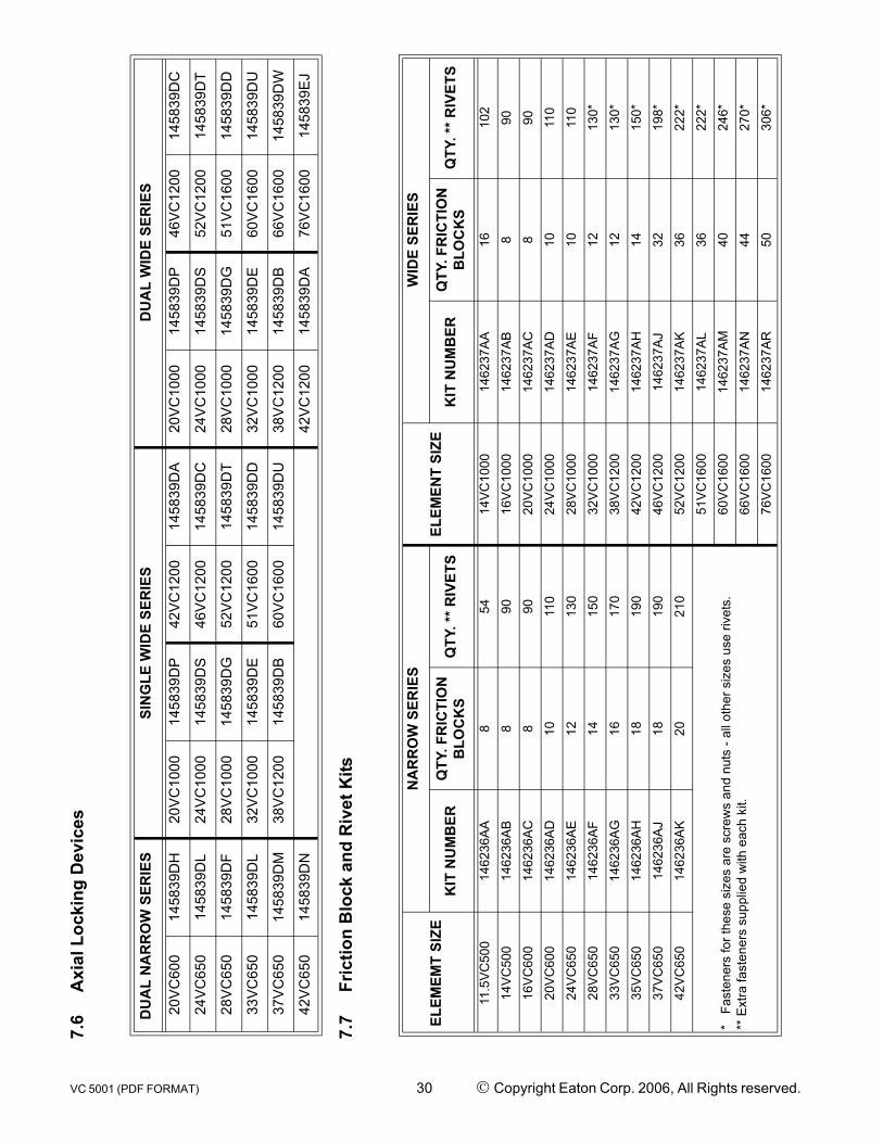
7.6
Axi
al L
ocki
ng D
evic
es
7.7
Fric
tion
Blo
ck a
nd R
ivet
Kits
DU
AL
NA
RR
OW
SER
IES
SIN
GLE
WID
E SE
RIE
SD
UA
L W
IDE
SER
IES
20V
C60
014
5839
DH
20V
C10
0014
5839
DP
42V
C12
0014
5839
DA
20V
C10
0014
5839
DP
46V
C12
0014
5839
DC
24V
C65
014
5839
DL
24V
C10
0014
5839
DS
46V
C12
0014
5839
DC
24V
C10
0014
5839
DS
52V
C12
0014
5839
DT
28V
C65
014
5839
DF
28V
C10
0014
5839
DG
52V
C12
0014
5839
DT
28V
C10
0014
5839
DG
51V
C16
0014
5839
DD
33V
C65
014
5839
DL
32V
C10
0014
5839
DE
51V
C16
0014
5839
DD
32V
C10
0014
5839
DE
60V
C16
0014
5839
DU
37V
C65
014
5839
DM
38V
C12
0014
5839
DB
60V
C16
0014
5839
DU
38V
C12
0014
5839
DB
66V
C16
0014
5839
DW
42V
C65
014
5839
DN
42V
C12
0014
5839
DA
76V
C16
0014
5839
EJ
ELEM
EMT
SIZE
NA
RR
OW
SER
IES
ELEM
ENT
SIZE
WID
E SE
RIE
S
KIT
NU
MB
ERQ
TY. F
RIC
TIO
N
BLO
CK
SQ
TY. *
* RIV
ETS
KIT
NU
MB
ERQ
TY. F
RIC
TIO
N
BLO
CK
SQ
TY. *
* RIV
ETS
11.5
VC50
014
6236
AA8
5414
VC10
0014
6237
AA16
102
14VC
500
1462
36AB
890
16VC
1000
1462
37AB
890
16VC
600
1462
36AC
890
20VC
1000
1462
37AC
890
20VC
600
1462
36AD
1011
024
VC10
0014
6237
AD10
110
24VC
650
1462
36AE
1213
028
VC10
0014
6237
AE10
110
28VC
650
1462
36AF
1415
032
VC10
0014
6237
AF12
130*
33VC
650
1462
36AG
1617
038
VC12
0014
6237
AG12
130*
35VC
650
1462
36AH
1819
042
VC12
0014
6237
AH14
150*
37VC
650
1462
36AJ
1819
046
VC12
0014
6237
AJ32
198*
42VC
650
1462
36AK
2021
052
VC12
0014
6237
AK36
222*
* F
aste
ners
for t
hese
siz
es a
re s
crew
s an
d nu
ts -
all o
ther
siz
es u
se ri
vets
.**
Ext
ra fa
sten
ers
supp
lied
with
eac
h ki
t.
51VC
1600
1462
37AL
3622
2*
60VC
1600
1462
37AM
4024
6*
66VC
1600
1462
37AN
4427
0*
76VC
1600
1462
37AR
5030
6*
VC 5001 (PDF FORMAT) 30 © Copyright Eaton Corp. 2006, All Rights reserved.

7.8
Fric
tion
Shoe
Ass
embl
y, T
orqu
e ba
r and
Rel
ease
Spr
ing
Kits
ELEM
EMT
SIZE
NA
RR
OW
SER
IES
ELEM
ENT
SIZE
WID
E SE
RIE
S
KIT
N
UM
BER
QTY
. FR
ICTI
ON
SH
OES
QTY
. TO
RQ
UE
BA
RS
QTY
. SP
RIN
GS
KIT
N
UM
BER
QTY
. FR
ICTI
ON
SH
OES
QTY
. TO
RQ
UE
BA
RS
QTY
. SP
RIN
GS
11.5
VC50
014
6236
A8
88
14VC
1000
1462
37A
88
8
14VC
500
1462
36B
88
816
VC10
0014
6237
B8
88
16VC
600
1462
36C
88
820
VC10
0014
6237
C8
88
20VC
600
1462
36D
1010
1024
VC10
0014
6237
D10
1010
24VC
650
1462
36E
1212
1228
VC10
0014
6237
E10
1010
28VC
650
1462
36F
1414
1432
VC10
0014
6237
F12
1212
33VC
650
1462
36G
1616
1638
VC12
0014
6237
G12
1212
35VC
650
1462
36H
1818
1842
VC12
0014
6237
H14
1414
37VC
650
1462
36J
1818
1846
VC12
0014
6237
J16
1616
42VC
650
1462
36K
2020
2052
VC12
0014
6237
K18
1818
51VC
1600
1462
37L
1818
36
60VC
1600
1462
37M
2020
40
66VC
1600
1462
37N
2222
44
76VC
1600
1462
37V
2525
50
VC 5001 (PDF FORMAT) 31 © Copyright Eaton Corp. 2006, All Rights reserved.

Form ML-318Revised September 3, 1997
EATON PRODUCT WARRANTYSubject to the conditions stated herein, Eaton Corporation warrants to the Purchaser that each new Airflex Product manufactured by Eaton will be free from failures caused by defects in material and workmanship, and will deliver its rated capacity, for a period of twelve (12) months from the date of shipment to Pur-chaser, provided such Product is properly installed, properly maintained, operated under normal conditions and with competent supervi-sion. Warranty claims shall, be made in writing and the part or parts shall, if requested by Air-flex Division, be returned repaid to the Airflex Division for inspection.Upon a determination that a defect exists, Eaton shall thereupon cor-rect any defect, at its option either by repairing any defective part or parts or by making avail-able at Eaton’s plant a repaired or replacement part. This warranty does not extend to normal wear parts or components of the Product, such as friction material and friction surfaces.
LIMITATION OF WARRANTYTHE FOREGOING WARRANTY IS EXCLUSIVE AND IN LIEU OF ALL OTHER WARRANTIES WHETHER WRITTEN, ORAL OR IMPLIED. ANY IMPLIED WARRANTY OF MERCHANTABILITY OR FITNESS FOR A PARTICULAR PURPOSE ARE SPECIFICALLY EXCLUDED.
In no event shall Eaton be liable for special, incidental or consequential damages. Eaton’s liability arising out of the supplying of such Product, or its use, whether in warranty, con-tract or otherwise, shall in no case exceed the cost of correcting defects in the Products as herein provided. Upon expiration of the twelve (12) month period, all such liability shall termi-nate. THE FOREGOING SHALL CONSTITUTE THE SOLE REMEDY OF PURCHASER AND THE SOLE LIABILITY OF EATON.
Eaton CorporationAirfiex Division
9919 Clinton RoadCleveland, Ohio 44144