Embed Size (px)
Citation preview
October 10, 1983OM-01934-OB02CDSW
Rev. H 12/12/01
THE GORMAN-RUPP COMPANY D MANSFIELD, OHIOGORMAN-RUPP OF CANADA LIMITED D ST. THOMAS, ONTARIO, CANADA Printed in U.S.A.
eCopyright by the Gorman-Rupp Company
INSTALLATION, OPERATION,AND MAINTENANCE MANUAL
WITH PARTS LIST
T---SERIES PUMP
MODEL
T6A61-BINCLUDING: /F, /FM
TABLE OF CONTENTS
i
INTRODUCTION PAGE I --- 1. . . . . . . . . . . . . . . . . . . . . . . . . . . . . . . . . . . . . . . . . . . . . . . . .
SAFETY --- SECTION A PAGE A --- 1. . . . . . . . . . . . . . . . . . . . . . . . . . . . . . . . . . . . . . . . . . .
INSTALLATION --- SECTION B PAGE B --- 1. . . . . . . . . . . . . . . . . . . . . . . . . . . . . . . . . . . .
Pump Dimensions PAGE B --- 1. . . . . . . . . . . . . . . . . . . . . . . . . . . . . . . . . . . . . . . . . . . . . . . . . . . . .PREINSTALLATION INSPECTION PAGE B --- 2. . . . . . . . . . . . . . . . . . . . . . . . . . . . . . . . . . . . . . . . . . . .POSITIONING PUMP PAGE B --- 2. . . . . . . . . . . . . . . . . . . . . . . . . . . . . . . . . . . . . . . . . . . . . . . . . . . . . . .
Lifting PAGE B --- 2. . . . . . . . . . . . . . . . . . . . . . . . . . . . . . . . . . . . . . . . . . . . . . . . . . . . . . . . . . . . . . . . .Mounting PAGE B --- 2. . . . . . . . . . . . . . . . . . . . . . . . . . . . . . . . . . . . . . . . . . . . . . . . . . . . . . . . . . . . .Clearance PAGE B --- 2. . . . . . . . . . . . . . . . . . . . . . . . . . . . . . . . . . . . . . . . . . . . . . . . . . . . . . . . . . . . .
SUCTION AND DISCHARGE PIPING PAGE B --- 2. . . . . . . . . . . . . . . . . . . . . . . . . . . . . . . . . . . . . . . . .Materials PAGE B --- 2. . . . . . . . . . . . . . . . . . . . . . . . . . . . . . . . . . . . . . . . . . . . . . . . . . . . . . . . . . . . . .Line Configuration PAGE B --- 3. . . . . . . . . . . . . . . . . . . . . . . . . . . . . . . . . . . . . . . . . . . . . . . . . . . . . .Connections to Pump PAGE B --- 3. . . . . . . . . . . . . . . . . . . . . . . . . . . . . . . . . . . . . . . . . . . . . . . . . .Gauges PAGE B --- 3. . . . . . . . . . . . . . . . . . . . . . . . . . . . . . . . . . . . . . . . . . . . . . . . . . . . . . . . . . . . . . .
SUCTION LINES PAGE B --- 3. . . . . . . . . . . . . . . . . . . . . . . . . . . . . . . . . . . . . . . . . . . . . . . . . . . . . . . . . . .Fittings PAGE B --- 3. . . . . . . . . . . . . . . . . . . . . . . . . . . . . . . . . . . . . . . . . . . . . . . . . . . . . . . . . . . . . . .Strainers PAGE B --- 3. . . . . . . . . . . . . . . . . . . . . . . . . . . . . . . . . . . . . . . . . . . . . . . . . . . . . . . . . . . . . .Sealing PAGE B --- 3. . . . . . . . . . . . . . . . . . . . . . . . . . . . . . . . . . . . . . . . . . . . . . . . . . . . . . . . . . . . . . .Suction Lines In Sumps PAGE B --- 3. . . . . . . . . . . . . . . . . . . . . . . . . . . . . . . . . . . . . . . . . . . . . . . . .Suction Line Positioning PAGE B --- 4. . . . . . . . . . . . . . . . . . . . . . . . . . . . . . . . . . . . . . . . . . . . . . . .
DISCHARGE LINES PAGE B --- 4. . . . . . . . . . . . . . . . . . . . . . . . . . . . . . . . . . . . . . . . . . . . . . . . . . . . . . . .Siphoning PAGE B --- 4. . . . . . . . . . . . . . . . . . . . . . . . . . . . . . . . . . . . . . . . . . . . . . . . . . . . . . . . . . . . .Valves PAGE B --- 4. . . . . . . . . . . . . . . . . . . . . . . . . . . . . . . . . . . . . . . . . . . . . . . . . . . . . . . . . . . . . . . .Bypass Lines PAGE B --- 5. . . . . . . . . . . . . . . . . . . . . . . . . . . . . . . . . . . . . . . . . . . . . . . . . . . . . . . . . .
AUTOMATIC AIR RELEASE VALVE PAGE B --- 6. . . . . . . . . . . . . . . . . . . . . . . . . . . . . . . . . . . . . . . . . . .Theory of Operation PAGE B --- 6. . . . . . . . . . . . . . . . . . . . . . . . . . . . . . . . . . . . . . . . . . . . . . . . . . . .Air Release Valve Installation PAGE B --- 6. . . . . . . . . . . . . . . . . . . . . . . . . . . . . . . . . . . . . . . . . . . .
ALIGNMENT PAGE B --- 7. . . . . . . . . . . . . . . . . . . . . . . . . . . . . . . . . . . . . . . . . . . . . . . . . . . . . . . . . . . . . .Coupled Drives PAGE B --- 8. . . . . . . . . . . . . . . . . . . . . . . . . . . . . . . . . . . . . . . . . . . . . . . . . . . . . . . .V-Belt Drives PAGE B --- 8. . . . . . . . . . . . . . . . . . . . . . . . . . . . . . . . . . . . . . . . . . . . . . . . . . . . . . . . . . .
OPERATION --- SECTION C PAGE C --- 1. . . . . . . . . . . . . . . . . . . . . . . . . . . . . . . . . . . . . .
PRIMING PAGE C --- 1. . . . . . . . . . . . . . . . . . . . . . . . . . . . . . . . . . . . . . . . . . . . . . . . . . . . . . . . . . . . . . . . .STARTING PAGE C --- 1. . . . . . . . . . . . . . . . . . . . . . . . . . . . . . . . . . . . . . . . . . . . . . . . . . . . . . . . . . . . . . . .
Rotation PAGE C --- 1. . . . . . . . . . . . . . . . . . . . . . . . . . . . . . . . . . . . . . . . . . . . . . . . . . . . . . . . . . . . . .OPERATION PAGE C --- 2. . . . . . . . . . . . . . . . . . . . . . . . . . . . . . . . . . . . . . . . . . . . . . . . . . . . . . . . . . . . . .
Lines With a Bypass PAGE C --- 2. . . . . . . . . . . . . . . . . . . . . . . . . . . . . . . . . . . . . . . . . . . . . . . . . . . .Lines Without a Bypass PAGE C --- 2. . . . . . . . . . . . . . . . . . . . . . . . . . . . . . . . . . . . . . . . . . . . . . . . .Leakage PAGE C --- 2. . . . . . . . . . . . . . . . . . . . . . . . . . . . . . . . . . . . . . . . . . . . . . . . . . . . . . . . . . . . . .Liquid Temperature And Overheating PAGE C --- 2. . . . . . . . . . . . . . . . . . . . . . . . . . . . . . . . . . . . .Strainer Check PAGE C --- 3. . . . . . . . . . . . . . . . . . . . . . . . . . . . . . . . . . . . . . . . . . . . . . . . . . . . . . . . .Pump Vacuum Check PAGE C --- 3. . . . . . . . . . . . . . . . . . . . . . . . . . . . . . . . . . . . . . . . . . . . . . . . . .
STOPPING PAGE C --- 3. . . . . . . . . . . . . . . . . . . . . . . . . . . . . . . . . . . . . . . . . . . . . . . . . . . . . . . . . . . . . . . .Cold Weather Preservation PAGE C --- 3. . . . . . . . . . . . . . . . . . . . . . . . . . . . . . . . . . . . . . . . . . . . . .
BEARING TEMPERATURE CHECK PAGE C --- 3. . . . . . . . . . . . . . . . . . . . . . . . . . . . . . . . . . . . . . . . . .
TABLE OF CONTENTS(continued)
ii
TROUBLESHOOTING --- SECTION D PAGE D --- 1. . . . . . . . . . . . . . . . . . . . . . . . . . . . . .
PREVENTIVE MAINTENANCE PAGE D --- 3. . . . . . . . . . . . . . . . . . . . . . . . . . . . . . . . . . . . . . . . . . . . . . .
PUMP MAINTENANCE AND REPAIR --- SECTION E PAGE E --- 1. . . . . . . . . . . . . . . .
PERFORMANCE CURVE PAGE E --- 1. . . . . . . . . . . . . . . . . . . . . . . . . . . . . . . . . . . . . . . . . . . . . . . . . . .PARTS LISTS:
Pump Model PAGE E --- 3. . . . . . . . . . . . . . . . . . . . . . . . . . . . . . . . . . . . . . . . . . . . . . . . . . . . . . . . . .Repair Rotating Assembly PAGE E --- 5. . . . . . . . . . . . . . . . . . . . . . . . . . . . . . . . . . . . . . . . . . . . . . .
PUMP AND SEAL DISASSEMBLY AND REASSEMBLY PAGE E --- 6. . . . . . . . . . . . . . . . . . . . . . . . .Back Cover And Wear Plate Removal PAGE E --- 6. . . . . . . . . . . . . . . . . . . . . . . . . . . . . . . . . . . . .Suction Check Valve Removal PAGE E --- 6. . . . . . . . . . . . . . . . . . . . . . . . . . . . . . . . . . . . . . . . . . .Rotating Assembly Removal PAGE E --- 7. . . . . . . . . . . . . . . . . . . . . . . . . . . . . . . . . . . . . . . . . . . . .Impeller Removal PAGE E --- 8. . . . . . . . . . . . . . . . . . . . . . . . . . . . . . . . . . . . . . . . . . . . . . . . . . . . . .Seal Removal PAGE E --- 8. . . . . . . . . . . . . . . . . . . . . . . . . . . . . . . . . . . . . . . . . . . . . . . . . . . . . . . . . .Shaft and Bearing Removal and Disassembly PAGE E --- 8. . . . . . . . . . . . . . . . . . . . . . . . . . . . .Shaft and Bearing Reassembly and Installation PAGE E --- 9. . . . . . . . . . . . . . . . . . . . . . . . . . . .Seal Installation PAGE E --- 10. . . . . . . . . . . . . . . . . . . . . . . . . . . . . . . . . . . . . . . . . . . . . . . . . . . . . . . .Impeller Installation PAGE E --- 12. . . . . . . . . . . . . . . . . . . . . . . . . . . . . . . . . . . . . . . . . . . . . . . . . . . . .Rotating Assembly Installation PAGE E --- 12. . . . . . . . . . . . . . . . . . . . . . . . . . . . . . . . . . . . . . . . . . .Suction Check Valve Installation PAGE E --- 13. . . . . . . . . . . . . . . . . . . . . . . . . . . . . . . . . . . . . . . . .Back Cover Installation PAGE E --- 13. . . . . . . . . . . . . . . . . . . . . . . . . . . . . . . . . . . . . . . . . . . . . . . . .
PRESSURE RELIEF VALVE MAINTENANCE PAGE E --- 13. . . . . . . . . . . . . . . . . . . . . . . . . . . . . . . . . .Final Pump Assembly PAGE E --- 13. . . . . . . . . . . . . . . . . . . . . . . . . . . . . . . . . . . . . . . . . . . . . . . . . .
LUBRICATION PAGE E --- 14. . . . . . . . . . . . . . . . . . . . . . . . . . . . . . . . . . . . . . . . . . . . . . . . . . . . . . . . . . . . .Seal Assembly PAGE E --- 14. . . . . . . . . . . . . . . . . . . . . . . . . . . . . . . . . . . . . . . . . . . . . . . . . . . . . . . . .Bearings PAGE E --- 14. . . . . . . . . . . . . . . . . . . . . . . . . . . . . . . . . . . . . . . . . . . . . . . . . . . . . . . . . . . . . .Power Source PAGE E --- 14. . . . . . . . . . . . . . . . . . . . . . . . . . . . . . . . . . . . . . . . . . . . . . . . . . . . . . . . .
T SERIES OM--01934
PAGE I -- 1INTRODUCTION
INTRODUCTION
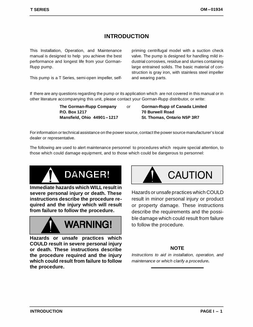
This Installation, Operation, and Maintenancemanual is designed to help you achieve the bestperformance and longest life from your Gorman-Rupp pump.
This pump is a T Series, semi-open impeller, self-
priming centrifugal model with a suction checkvalve. The pump is designed for handling mild in-dustrial corrosives, residue and slurries containinglarge entrained solids. The basic material of con-struction is gray iron, with stainless steel impellerand wearing parts.
If there are any questions regarding the pump or its application which are not covered in this manual or inother literature accompanying this unit, please contact your Gorman-Rupp distributor, or write:
The Gorman-Rupp Company or Gorman-Rupp of Canada LimitedP.O. Box 1217 70 Burwell RoadMansfield, Ohio 44901--1217 St. Thomas, Ontario N5P 3R7
For information or technical assistance on the power source, contact the power source manufacturer’s localdealer or representative.
The following are used to alert maintenance personnel to procedures which require special attention, tothose which could damage equipment, and to those which could be dangerous to personnel:
Immediate hazards which WILL result insevere personal injury or death. Theseinstructions describe the procedure re-quired and the injury which will resultfrom failure to follow the procedure.
Hazards or unsafe practices whichCOULD result in severe personal injuryor death. These instructions describethe procedure required and the injurywhich could result from failure to followthe procedure.
Hazards or unsafe practices which COULDresult in minor personal injury or productor property damage. These instructionsdescribe the requirements and the possi-ble damage which could result from failureto follow the procedure.
NOTEInstructions to aid in installation, operation, andmaintenance or which clarify a procedure.
T SERIES OM--01934
PAGE A -- 1SAFETY
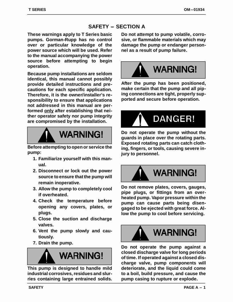
SAFETY --- SECTION AThese warnings apply to T Series basicpumps. Gorman-Rupp has no controlover or particular knowledge of thepower source which will be used. Referto the manual accompanying the powersource before attempting to beginoperation.
Because pump installations are seldomidentical, this manual cannot possiblyprovide detailed instructions and pre-cautions for each specific application.Therefore, it is the owner/installer’s re-sponsibility to ensure that applicationsnot addressed in this manual are per-formed only after establishing that nei-ther operator safety nor pump integrityare compromised by the installation.
Before attempting to open or service thepump:
1. Familiarize yourself with this man-ual.
2. Disconnect or lock out the powersource to ensure that the pump willremain inoperative.
3. Allow the pump to completely coolif overheated.
4. Check the temperature beforeopening any covers, plates, orplugs.
5. Close the suction and dischargevalves.
6. Vent the pump slowly and cau-tiously.
7. Drain the pump.
This pump is designed to handle mildindustrial corrosives, residues and slur-ries containing large entrained solids.
Do not attempt to pump volatile, corro-sive, or flammable materials which maydamage the pump or endanger person-nel as a result of pump failure.
After the pump has been positioned,make certain that the pump and all pip-ing connections are tight, properly sup-ported and secure before operation.
Do not operate the pump without theguards in place over the rotating parts.Exposed rotating parts can catch cloth-ing, fingers, or tools, causing severe in-jury to personnel.
Do not remove plates, covers, gauges,pipe plugs, or fittings from an over-heated pump. Vapor pressure within thepump can cause parts being disen-gaged to be ejected with great force. Al-low the pump to cool before servicing.
Do not operate the pump against aclosed discharge valve for long periodsof time. If operated against a closed dis-charge valve, pump components willdeteriorate, and the liquid could cometo a boil, build pressure, and cause thepump casing to rupture or explode.
T SERIESOM--01934
PAGE A -- 2 SAFETY
This pump is designed to handle materi-als which could cause illness or injurythrough direct exposure or emittedfumes. Wear adequate protective cloth-ing when working on this pump or pip-ing.
Use lifting and moving equipment ingood repair and with adequate capacityto prevent injuries to personnel or dam-age to equipment. Suction and dis-charge hoses and piping must be re-moved from the pump before lifting.
OM--01934T SERIES
PAGE B -- 1INSTALLATION
INSTALLATION --- SECTION B
Review all SAFETY information in Section A.
Since pump installations are seldom identical, thissection offers only general recommendations andpractices required to inspect, position, and ar-range the pump and piping.
Most of the information pertains to a standardstatic lift application where the pump is posi-tioned above the free level of liquid to be pumped.
If installed in a flooded suction application wherethe liquid is supplied to the pump under pressure,some of the information such as mounting, lineconfiguration, and priming must be tailored to the
specific application. Since the pressure suppliedto the pump is critical to performance and safety,be sure to limit the incoming pressure to 50% ofthe maximum permissible operating pressure asshown on the pump performance curve.
For further assistance, contact your Gorman-Ruppdistributor or the Gorman-Rupp Company.
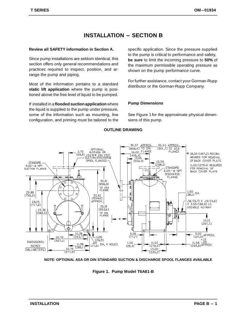
Pump Dimensions
See Figure 1 for the approximate physical dimen-sions of this pump.
OUTLINE DRAWING
NOTE: OPTIONAL ASA OR DIN STANDARD SUCTION & DISCHARGE SPOOL FLANGES AVAILABLE
Figure 1. Pump Model T6A61-B
OM--01934 T SERIES
PAGE B -- 2 INSTALLATION
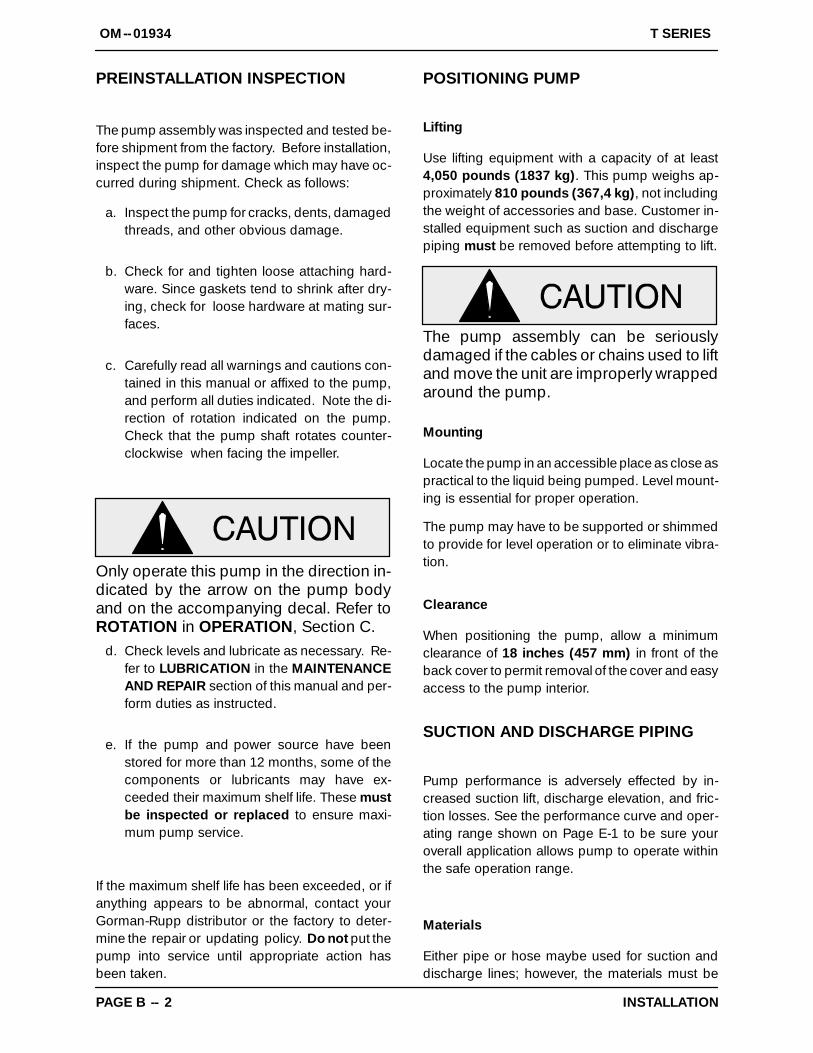
PREINSTALLATION INSPECTION
The pump assembly was inspected and tested be-fore shipment from the factory. Before installation,inspect the pump for damage which may have oc-curred during shipment. Check as follows:
a. Inspect the pump for cracks, dents, damagedthreads, and other obvious damage.
b. Check for and tighten loose attaching hard-ware. Since gaskets tend to shrink after dry-ing, check for loose hardware at mating sur-faces.
c. Carefully read all warnings and cautions con-tained in this manual or affixed to the pump,and perform all duties indicated. Note the di-rection of rotation indicated on the pump.Check that the pump shaft rotates counter-clockwise when facing the impeller.
Only operate this pump in the direction in-dicated by the arrow on the pump bodyand on the accompanying decal. Refer toROTATION in OPERATION, Section C.
d. Check levels and lubricate as necessary. Re-fer to LUBRICATION in the MAINTENANCEAND REPAIR section of this manual and per-form duties as instructed.
e. If the pump and power source have beenstored for more than 12 months, some of thecomponents or lubricants may have ex-ceeded their maximum shelf life. These mustbe inspected or replaced to ensure maxi-mum pump service.
If the maximum shelf life has been exceeded, or ifanything appears to be abnormal, contact yourGorman-Rupp distributor or the factory to deter-mine the repair or updating policy. Do not put thepump into service until appropriate action hasbeen taken.
POSITIONING PUMP
Lifting
Use lifting equipment with a capacity of at least4,050 pounds (1837 kg). This pump weighs ap-proximately 810 pounds (367,4 kg), not includingthe weight of accessories and base. Customer in-stalled equipment such as suction and dischargepiping must be removed before attempting to lift.
The pump assembly can be seriouslydamaged if the cables or chains used to liftand move the unit are improperly wrappedaround the pump.
Mounting
Locate the pump in an accessible place as close aspractical to the liquid being pumped. Level mount-ing is essential for proper operation.
The pump may have to be supported or shimmedto provide for level operation or to eliminate vibra-tion.
Clearance
When positioning the pump, allow a minimumclearance of 18 inches (457 mm) in front of theback cover to permit removal of the cover and easyaccess to the pump interior.
SUCTION AND DISCHARGE PIPING
Pump performance is adversely effected by in-creased suction lift, discharge elevation, and fric-tion losses. See the performance curve and oper-ating range shown on Page E-1 to be sure youroverall application allows pump to operate withinthe safe operation range.
Materials
Either pipe or hose maybe used for suction anddischarge lines; however, the materials must be
OM--01934T SERIES
PAGE B -- 3INSTALLATION
compatible with the liquid being pumped. If hose isused in suction lines, it must be the rigid-wall, rein-forced type to prevent collapse under suction. Us-ing piping couplings in suction lines is not recom-mended.
Line Configuration
Keep suction and discharge lines as straight aspossible to minimize friction losses. Make mini-mum use of elbows and fittings, which substan-tially increase friction loss. If elbows are necessary,use the long-radius type to minimize friction loss.
Connections to Pump
Before tightening a connecting flange, align it ex-actly with the pump port. Never pull a pipe line intoplace by tightening the flange bolts and/or cou-plings.
Lines near the pump must be independently sup-ported to avoid strain on the pump which couldcause excessive vibration, decreased bearing life,and increased shaft and seal wear. If hose-typelines are used, they should have adequate supportto secure them when filled with liquid and underpressure.
Gauges
Most pumps are drilled and tapped for installingdischarge pressure and vacuum suction gauges.If these gauges are desired for pumps that are nottapped, drill and tap the suction and dischargelines not less than 18 inches (457,2 mm) from thesuction and discharge ports and install the lines.Installation closer to the pump may result in erraticreadings.
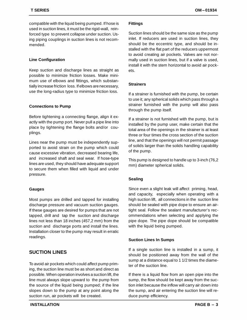
SUCTION LINES
To avoid air pockets which could affect pump prim-ing, the suction line must be as short and direct aspossible. When operation involves a suction lift, theline must always slope upward to the pump fromthe source of the liquid being pumped; if the lineslopes down to the pump at any point along thesuction run, air pockets will be created.
Fittings
Suction lines should be the same size as the pumpinlet. If reducers are used in suction lines, theyshould be the eccentric type, and should be in-stalled with the flat part of the reducers uppermostto avoid creating air pockets. Valves are not nor-mally used in suction lines, but if a valve is used,install it with the stem horizontal to avoid air pock-ets.
Strainers
If a strainer is furnished with the pump, be certainto use it; any spherical solids which pass through astrainer furnished with the pump will also passthrough the pump itself.
If a strainer is not furnished with the pump, but isinstalled by the pump user, make certain that thetotal area of the openings in the strainer is at leastthree or four times the cross section of the suctionline, and that the openings will not permit passageof solids larger than the solids handling capabilityof the pump.
This pump is designed to handle up to 3-inch (76,2mm) diameter spherical solids.
Sealing
Since even a slight leak will affect priming, head,and capacity, especially when operating with ahigh suction lift, all connections in the suction lineshould be sealed with pipe dope to ensure an air-tight seal. Follow the sealant manufacturer’s rec-ommendations when selecting and applying thepipe dope. The pipe dope should be compatiblewith the liquid being pumped.
Suction Lines In Sumps
If a single suction line is installed in a sump, itshould be positioned away from the wall of thesump at a distance equal to 1 1/2 times the diame-ter of the suction line.
If there is a liquid flow from an open pipe into thesump, the flow should be kept away from the suc-tion inlet because the inflow will carry air down intothe sump, and air entering the suction line will re-duce pump efficiency.
OM--01934 T SERIES
PAGE B -- 4 INSTALLATION
If it is necessary to position inflow close to the suc-tion inlet, install a baffle between the inflow and thesuction inlet at a distance 1 1/2 times the diameterof the suction pipe. The baffle will allow entrainedair to escape from the liquid before it is drawn intothe suction inlet.
If two suction lines are installed in a single sump,the flow paths may interact, reducing the efficiencyof one or both pumps. To avoid this, position thesuction inlets so that they are separated by a dis-tance equal to at least 3 times the diameter of thesuction pipe.
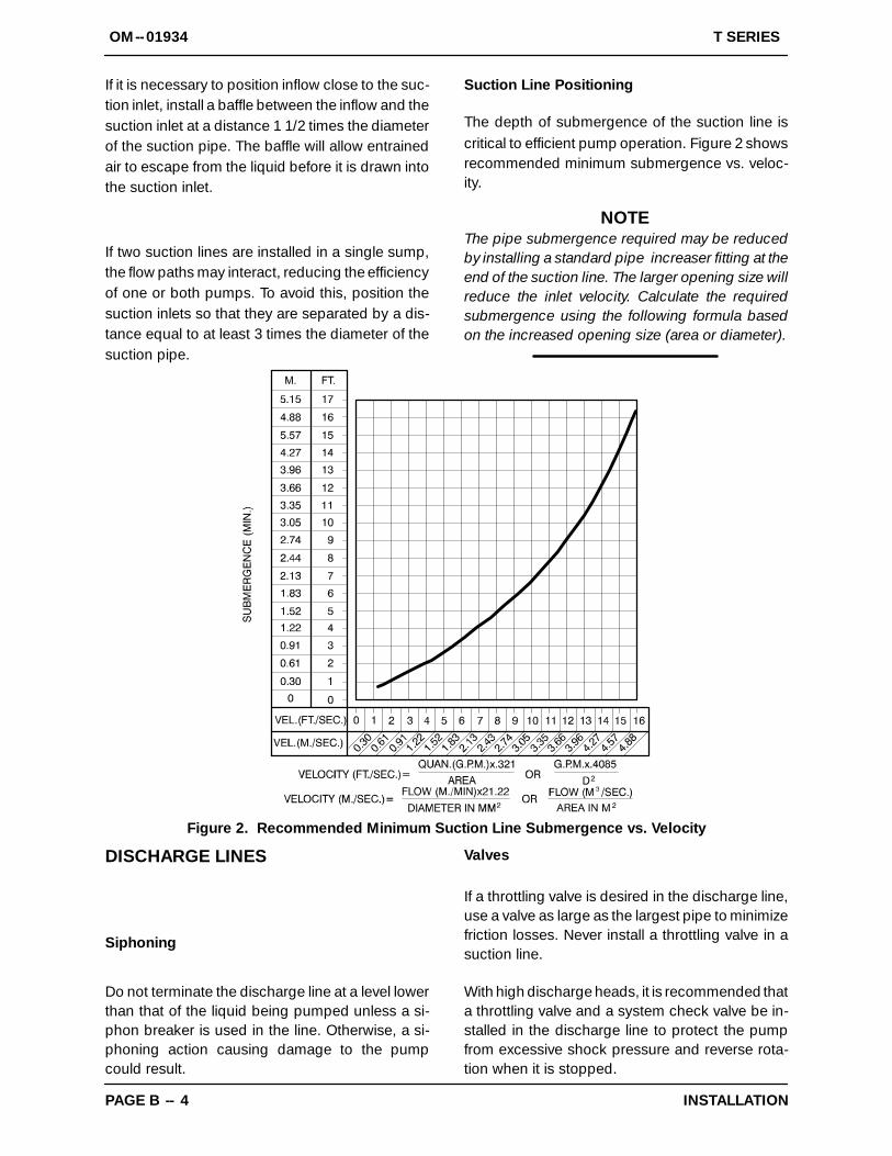
Suction Line Positioning
The depth of submergence of the suction line iscritical to efficient pump operation. Figure 2 showsrecommended minimum submergence vs. veloc-ity.
NOTEThe pipe submergence required may be reducedby installing a standard pipe increaser fitting at theend of the suction line. The larger opening size willreduce the inlet velocity. Calculate the requiredsubmergence using the following formula basedon the increased opening size (area or diameter).
Figure 2. Recommended Minimum Suction Line Submergence vs. Velocity
DISCHARGE LINES
Siphoning
Do not terminate the discharge line at a level lowerthan that of the liquid being pumped unless a si-phon breaker is used in the line. Otherwise, a si-phoning action causing damage to the pumpcould result.
Valves
If a throttling valve is desired in the discharge line,use a valve as large as the largest pipe to minimizefriction losses. Never install a throttling valve in asuction line.
With high discharge heads, it is recommended thata throttling valve and a system check valve be in-stalled in the discharge line to protect the pumpfrom excessive shock pressure and reverse rota-tion when it is stopped.
OM--01934T SERIES
PAGE B -- 5INSTALLATION
If the application involves a high dischargehead, gradually close the dischargethrottling valve before stopping the pump.
Bypass Lines
Self-priming pumps are not air compressors. Dur-ing the priming cycle, air from the suction line mustbe vented to atmosphere on the discharge side. Ifthe discharge line is open, this air will be ventedthrough the discharge. However, if a check valvehas been installed in the discharge line, the dis-charge side of the pump must be opened toatmos-pheric pressure through a bypass line installed be-tween the pump discharge and the check valve. Aself-priming centrifugal pump will not prime ifthere is sufficient static liquid head to hold the dis-charge check valve closed.
NOTEThe bypass line should be sized so that it does notaffect pump discharge capacity; however, the by-pass line should be at least 1 inch in diameter tominimize the chance of plugging.
In low discharge head applications (less than 30feet or 9 meters), it is recommended that the by-pass line be run back to the wet well, and located 6inches below the water level or cut-off point of thelow level pump. In some installations, this bypassline may be terminated with a six-to-eight footlength of 1 1/4 inch I.D. smooth-bore hose; air andliquid vented during the priming process will thenagitate the hose and break up any solids, grease,or other substances likely to cause clogging.
A bypass line that is returned to a wet wellmust be secured against being drawn intothe pump suction inlet.
It is also recommended that pipe unions be in-stalled at each 90_ elbow in a bypass line to easedisassembly and maintenance.
In high discharge head applications (more than30 feet), an excessive amount of liquid may be by-passed and forced back to the wet well under thefull working pressure of the pump; this will reduceoverall pumping efficiency. Therefore, it is recom-mended that a Gorman-Rupp Automatic Air Re-lease Valve be installed in the bypass line.
Gorman-Rupp Automatic Air Release Valves arereliable, and require minimum maintenance. SeeAUTOMATIC AIR RELEASE VALVE in this sectionfor installation and theory of operation of the Auto-matic Air Release Valve. Consult your Gorman-Rupp distributor, or contact the Gorman-RuppCompany for selection of an Automatic Air ReleaseValve to fit your application.
If the installation involves a flooded suction such asa below-ground lift station. A pipe union and manu-al shut-off valve may be installed in the bleed line toallow service of the valve without shutting down thestation, and to eliminate the possibility of flooding.If a manual shut-off valve is installed anywhere inthe air release piping, it must be a full-opening balltype valve to prevent plugging by solids.
If a manual shut-off valve is installed ina bypass line, it must not be left closedduring operation. A closed manual shut-off valve may cause a pump which haslost prime to continue to operate with-out reaching prime, causing dangerousoverheating and possible explosiverupture of the pump casing. Personnelcould be severely injured.
Allow an over-heated pump to cool be-fore servicing. Do not remove plates,covers, gauges, or fittings from an over-heated pump. Liquid within the pumpcan reach boiling temperatures, and va-por pressure within the pump can causeparts being disengaged to be ejectedwith great force. After the pump cools,drain the liquid from the pump by re-moving the casing drain plug. Use cau-
OM--01934 T SERIES
PAGE B -- 6 INSTALLATION
tion when removing the plug to preventinjury to personnel from hot liquid.
AUTOMATIC AIR RELEASE VALVE
When properly installed and correctly adjusted tothe specific hydraulic operating conditions of theapplication, the Gorman-Rupp Automatic Air Re-lease Valve will permit air to escape through the by-pass line, and then close automatically when thepump is fully primed and pumping at full capacity.
Theory of Operation
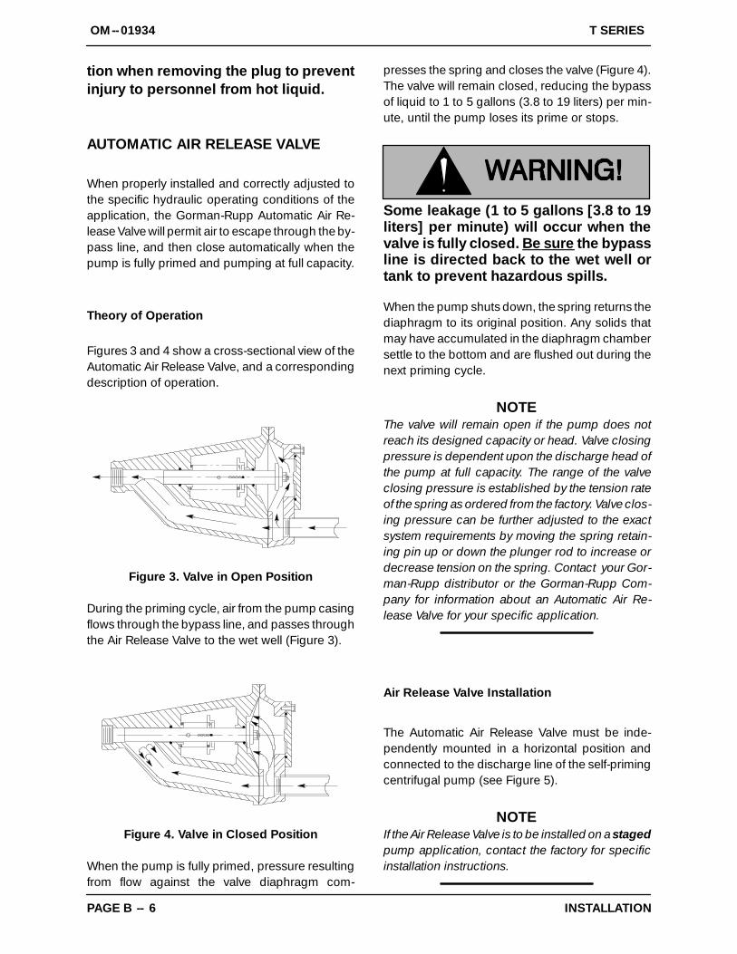
Figures 3 and 4 show a cross-sectional view of theAutomatic Air Release Valve, and a correspondingdescription of operation.
Figure 3. Valve in Open Position
During the priming cycle, air from the pump casingflows through the bypass line, and passes throughthe Air Release Valve to the wet well (Figure 3).
Figure 4. Valve in Closed Position
When the pump is fully primed, pressure resultingfrom flow against the valve diaphragm com-
presses the spring and closes the valve (Figure 4).The valve will remain closed, reducing the bypassof liquid to 1 to 5 gallons (3.8 to 19 liters) per min-ute, until the pump loses its prime or stops.
Some leakage (1 to 5 gallons [3.8 to 19liters] per minute) will occur when thevalve is fully closed. Be sure the bypassline is directed back to the wet well ortank to prevent hazardous spills.
When the pump shuts down, the spring returns thediaphragm to its original position. Any solids thatmay have accumulated in the diaphragm chambersettle to the bottom and are flushed out during thenext priming cycle.
NOTEThe valve will remain open if the pump does notreach its designed capacity or head. Valve closingpressure is dependent upon the discharge head ofthe pump at full capacity. The range of the valveclosing pressure is established by the tension rateof the spring as ordered from the factory. Valve clos-ing pressure can be further adjusted to the exactsystem requirements by moving the spring retain-ing pin up or down the plunger rod to increase ordecrease tension on the spring. Contact your Gor-man-Rupp distributor or the Gorman-Rupp Com-pany for information about an Automatic Air Re-lease Valve for your specific application.
Air Release Valve Installation
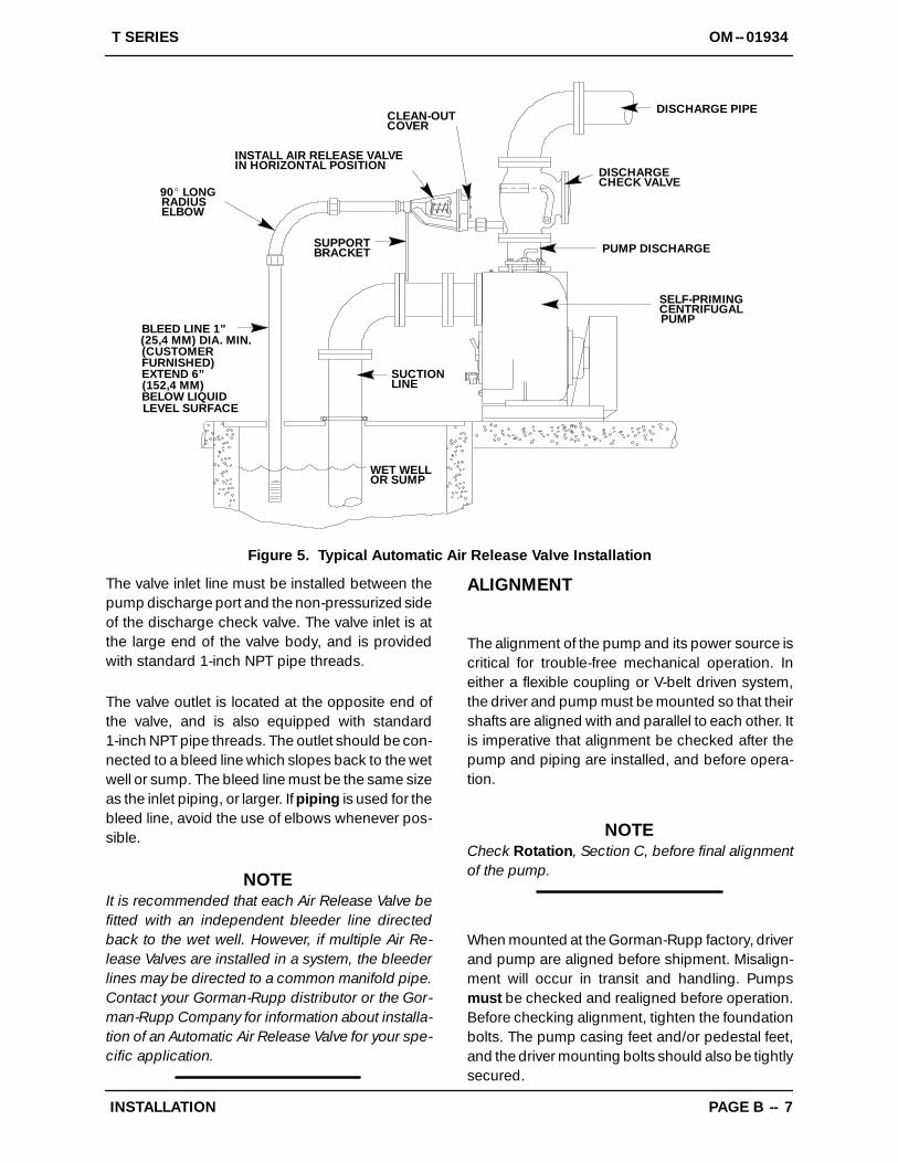
The Automatic Air Release Valve must be inde-pendently mounted in a horizontal position andconnected to the discharge line of the self-primingcentrifugal pump (see Figure 5).
NOTEIf the Air Release Valve is to be installed on a stagedpump application, contact the factory for specificinstallation instructions.
OM--01934T SERIES
PAGE B -- 7INSTALLATION
DISCHARGE PIPE
DISCHARGECHECK VALVE
PUMP DISCHARGE
SELF-PRIMINGCENTRIFUGALPUMP
SUCTIONLINE
SUPPORTBRACKET
CLEAN-OUTCOVER
INSTALL AIR RELEASE VALVEIN HORIZONTAL POSITION
90_ LONGRADIUSELBOW
BLEED LINE 1”(25,4 MM) DIA. MIN.(CUSTOMERFURNISHED)EXTEND 6”(152,4 MM)BELOW LIQUID
WET WELLOR SUMP
LEVEL SURFACE
Figure 5. Typical Automatic Air Release Valve Installation
The valve inlet line must be installed between thepump discharge port and the non-pressurized sideof the discharge check valve. The valve inlet is atthe large end of the valve body, and is providedwith standard 1-inch NPT pipe threads.
The valve outlet is located at the opposite end ofthe valve, and is also equipped with standard1-inch NPT pipe threads. The outlet should be con-nected to a bleed line which slopes back to the wetwell or sump. The bleed line must be the same sizeas the inlet piping, or larger. If piping is used for thebleed line, avoid the use of elbows whenever pos-sible.
NOTEIt is recommended that each Air Release Valve befitted with an independent bleeder line directedback to the wet well. However, if multiple Air Re-lease Valves are installed in a system, the bleederlines may be directed to a common manifold pipe.Contact your Gorman-Rupp distributor or the Gor-man-Rupp Company for information about installa-tion of an Automatic Air Release Valve for your spe-cific application.
ALIGNMENT
The alignment of the pump and its power source iscritical for trouble-free mechanical operation. Ineither a flexible coupling or V-belt driven system,the driver and pump must be mounted so that theirshafts are aligned with and parallel to each other. Itis imperative that alignment be checked after thepump and piping are installed, and before opera-tion.
NOTECheck Rotation, Section C, before final alignmentof the pump.
When mounted at the Gorman-Rupp factory, driverand pump are aligned before shipment. Misalign-ment will occur in transit and handling. Pumpsmust be checked and realigned before operation.Before checking alignment, tighten the foundationbolts. The pump casing feet and/or pedestal feet,and the driver mounting bolts should also be tightlysecured.
OM--01934 T SERIES
PAGE B -- 8 INSTALLATION
When checking alignment, disconnectthe power source to ensure that thepump will remain inoperative.
Adjusting the alignment in one directionmay alter the alignment in another direc-tion. check each procedure after alteringalignment.
Coupled Drives
When using couplings, the axis of the powersource must be aligned to the axis of the pumpshaft in both the horizontal and vertical planes.Most couplings require a specific gap or clearancebetween the driving and the driven shafts. Refer tothe coupling manufacturer’s service literature.
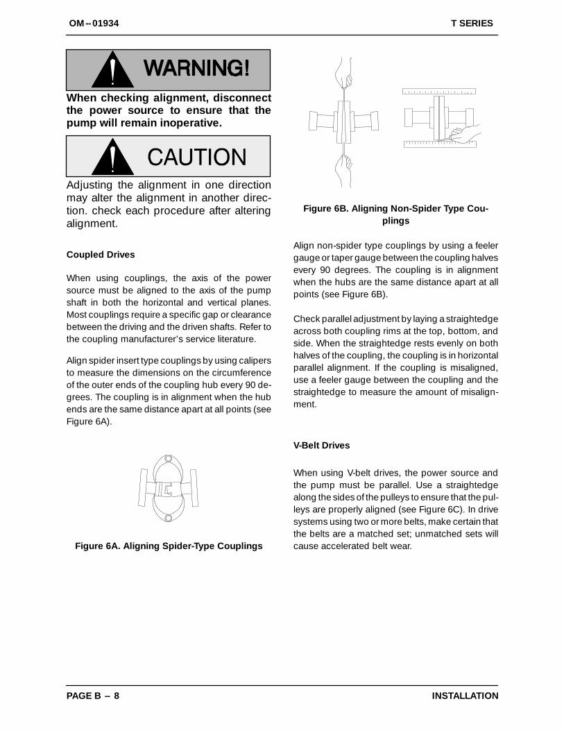
Align spider insert type couplings by using calipersto measure the dimensions on the circumferenceof the outer ends of the coupling hub every 90 de-grees. The coupling is in alignment when the hubends are the same distance apart at all points (seeFigure 6A).
Figure 6A. Aligning Spider-Type Couplings
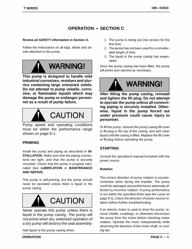
Figure 6B. Aligning Non-Spider Type Cou-plings
Align non-spider type couplings by using a feelergauge or taper gauge between the coupling halvesevery 90 degrees. The coupling is in alignmentwhen the hubs are the same distance apart at allpoints (see Figure 6B).
Check parallel adjustment by laying a straightedgeacross both coupling rims at the top, bottom, andside. When the straightedge rests evenly on bothhalves of the coupling, the coupling is in horizontalparallel alignment. If the coupling is misaligned,use a feeler gauge between the coupling and thestraightedge to measure the amount of misalign-ment.
V-Belt Drives
When using V-belt drives, the power source andthe pump must be parallel. Use a straightedgealong the sides of the pulleys to ensure that the pul-leys are properly aligned (see Figure 6C). In drivesystems using two or more belts, make certain thatthe belts are a matched set; unmatched sets willcause accelerated belt wear.

OM--01934T SERIES
PAGE B -- 9INSTALLATION
MISALIGNED:SHAFTS
NOT PARALLEL
MISALIGNED:SHAFTS
NOT IN LINE
ALIGNED: SHAFTSPARALLEL AND
SHEAVES IN LINEFigure 6C. Alignment of V-Belt Driven Pumps
Tighten the belts in accordance with the belt manu-facturer’s instructions. If the belts are too loose,they will slip; if the belts are too tight, there will beexcessive power loss and possible bearing failure.Select pulleys that will match the proper speed ra-tio; overspeeding the pump may damage bothpump and power source.
Do not operate the pump without theguard in place over the rotating parts.exposed rotating parts can catch cloth-ing, fingers, or tools, causing severe in-jury to personnel.
T SERIES OM--01934
OPERATION PAGE C -- 1
OPERATION --- SECTION C
Review all SAFETY information in Section A.
Follow the instructions on all tags, labels and de-cals attached to the pump.
This pump is designed to handle mildindustrial corrosives, residues and slur-ries containing large entrained solids.Do not attempt to pump volatile, corro-sive, or flammable liquids which maydamage the pump or endanger person-nel as a result of pump failure.
Pump speed and operating conditionsmust be within the performance rangeshown on page E-1.
PRIMING
Install the pump and piping as described in IN-STALLATION. Make sure that the piping connec-tions are tight, and that the pump is securelymounted. Check that the pump is properly lubri-cated (see LUBRICATION in MAINTENANCEAND REPAIR).
This pump is self-priming, but the pump shouldnever be operated unless there is liquid in thepump casing.
Never operate this pump unless there isliquid in the pump casing. The pump willnot prime when dry. extended operation ofa dry pump will destroy the seal assembly.
Add liquid to the pump casing when:
1. The pump is being put into service for thefirst time.
2. The pump has not been used for a consider-able length of time.
3. The liquid in the pump casing has evapo-rated.
Once the pump casing has been filled, the pumpwill prime and reprime as necessary.
After filling the pump casing, reinstalland tighten the fill plug. Do not attemptto operate the pump unless all connect-ing piping is securely installed. Other-wise, liquid in the pump forced outunder pressure could cause injury topersonnel.
To fill the pump, remove the pump casing fill coveror fill plug in the top of the casing, and add cleanliquid until the casing is filled. Replace the fill coveror fill plug before operating the pump.
STARTING
Consult the operations manual furnished with thepower source.
Rotation
The correct direction of pump rotation is counter-clockwise when facing the impeller. The pumpcould be damaged and performance adversely af-fected by incorrect rotation. If pump performanceis not within the specified limits (see the curve onpage E-1), check the direction of power source ro-tation before further troubleshooting.
If an electric motor is used to drive the pump, re-move V-belts, couplings, or otherwise disconnectthe pump from the motor before checking motorrotation. Operate the motor independently whileobserving the direction of the motor shaft, or cool-ing fan.
T SERIESOM--01934
OPERATIONPAGE C -- 2
If rotation is incorrect on a three-phase motor, havea qualified electrician interchange any two of thethree phase wires to change direction. If rotation isincorrect on a single-phase motor, consult the liter-ature supplied with the motor for specific instruc-tions.
OPERATION
Lines With a Bypass
If a Gorman-Rupp Automatic Air Release Valve hasbeen installed, the valve will automatically open toallow the pump to prime, and automatically closeafter priming is complete (see INSTALLATION forAir Release Valve operation).
If the bypass line is open, air from the suction linewill be discharged through the bypass line back tothe wet well during the priming cycle. Liquid willthen continue to circulate through the bypass linewhile the pump is in operation.
Lines Without a Bypass
Open all valves in the discharge line and start thepower source. Priming is indicated by a positivereading on the discharge pressure gauge or by aquieter operation. The pump may not prime imme-diately because the suction line must first fill withliquid. If the pump fails to prime within five minutes,stop it and check the suction line for leaks.
After the pump has been primed, partially close thedischarge line throttling valve in order to fill the lineslowly and guard against excessive shock pres-sure which could damage pipe ends, gaskets,sprinkler heads, and any other fixtures connectedto the line. When the discharge line is completelyfilled, adjust the throttling valve to the required flowrate.
Do not operate the pump against aclosed discharge throttling valve forlong periods of time. If operated againsta closed discharge throttling valve,pump components will deteriorate, and
the liquid could come to a boil, buildpressure, and cause the pump casing torupture or explode.
Leakage
No leakage should be visible at pump mating sur-faces, or at pump connections or fittings. Keep allline connections and fittings tight to maintain maxi-mum pump efficiency.
Liquid Temperature And Overheating
The maximum liquid temperature for this pump is160_ F (71_ C). Do not apply it at a higher operat-ing temperature.
Overheating can occur if operated with the valvesin the suction or discharge lines closed. Operatingagainst closed valves could bring the liquid to aboil, build pressure, and cause the pump to rup-ture or explode. If overheating occurs, stop thepump and allow it to cool before servicing it. Refill
the pump casing with cool liquid.
Allow an over-heated pump to cool be-fore servicing. Do not remove plates,covers, gauges, or fittings from an over-heated pump. Liquid within the pumpcan reach boiling temperatures, and va-por pressure within the pump can causeparts being disengaged to be ejectedwith great force. After the pump cools,drain the liquid from the pump by re-moving the casing drain plug. Use cau-tion when removing the plug to preventinjury to personnel from hot liquid.
As a safeguard against rupture or explosion due toheat, this pump is equipped with a pressure reliefvalve which will open if vapor pressure within thepump casing reaches a critical point. If overheatingdoes occur, stop the pump immediately and allowit to cool before servicing it. Approach any over-heated pump cautiously. It is recommended thatthe pressure relief valve assembly be replaced ateach overhaul, or any time the pump casing over-heats and activates the valve. Never replace this
T SERIES OM--01934
OPERATION PAGE C -- 3
valve with a substitute which has not been speci-fied or provided by the Gorman-Rupp Company.
Strainer Check
If a suction strainer has been shipped with thepump or installed by the user, check the strainerregularly, and clean it as necessary. The strainershould also be checked if pump flow rate begins todrop. If a vacuum suction gauge has been in-stalled, monitor and record the readings regularlyto detect strainer blockage.
Never introduce air or steam pressure into thepump casing or piping to remove a blockage. Thiscould result in personal injury or damage to theequipment. If backflushing is absolutely neces-sary, liquid pressure must be limited to 50% of themaximum permissible operating pressure shownon the pump performance curve.
Pump Vacuum Check
With the pump inoperative, install a vacuum gaugein the system, using pipe dope on the threads.Block the suction line and start the pump. At oper-ating speed the pump should pull a vacuum of 20inches (508,0 mm) or more of mercury. If it doesnot, check for air leaks in the seal, gasket, or dis-charge valve.
Open the suction line, and read the vacuum gaugewith the pump primed and at operation speed.Shut off the pump. The vacuum gauge reading willimmediately drop proportionate to static suctionlift, and should then stabilize. If the vacuum readingfalls off rapidly after stabilization, an air leak exists.Before checking for the source of the leak, checkthe point of installation of the vacuum gauge.
STOPPING
Never halt the flow of liquid suddenly. If the liquidbeing pumped is stopped abruptly, damagingshock waves can be transmitted to the pump andpiping system. Close all connecting valves slowly.
On engine driven pumps, reduce the throttlespeed slowly and allow the engine to idle briefly be-fore stopping.
If the application involves a high dischargehead, gradually close the dischargethrottling valve before stopping the pump.
After stopping the pump, lock out or disconnectthe power source to ensure that the pump will re-main inoperative.
Do not operate the pump against aclosed discharge throttling valve forlong periods of time. If operated againsta closed discharge throttling valve,pump components will deteriorate, andthe liquid could come to a boil, buildpressure, and cause the pump casing torupture or explode.
Cold Weather Preservation
In below freezing conditions, drain the pump toprevent damage from freezing. Also, clean out anysolids by flushing with a hose. Operate the pumpfor approximately one minute; this will remove anyremaining liquid that could freeze the pump rotat-ing parts. If the pump will be idle for more than afew hours, or if it has been pumping liquids con-taining a large amount of solids, drain the pump,and flush it thoroughly with clean water. To preventlarge solids from clogging the drain port and pre-venting the pump from completely draining, inserta rod or stiff wire in the drain port, and agitate theliquid during the draining process. Clean out anyremaining solids by flushing with a hose.
BEARING TEMPERATURE CHECK
Bearings normally run at higher than ambient tem-peratures because of heat generated by friction.Temperatures up to 160_F (71_ C) are considerednormal for bearings, and they can operate safely toat least 180_F (82_ C).
Checking bearing temperatures by hand is inaccu-rate. Bearing temperatures can be measured ac-
T SERIESOM--01934
OPERATIONPAGE C -- 4
curately by placing a contact-type thermometeragainst the housing. Record this temperature forfuture reference.
A sudden increase in bearing temperature is awarning that the bearings are at the point of failingto operate properly. Make certain that the bearinglubricant is of the proper viscosity and at the cor-rect level (see LUBRICATION in MAINTENANCE
AND REPAIR). Bearing overheating can also becaused by shaft misalignment and/or excessive vi-bration.
When pumps are first started, the bearings mayseem to run at temperatures above normal. Con-tinued operation should bring the temperaturesdown to normal levels.
T SERIES OM--01934
TROUBLESHOOTING PAGE D -- 1
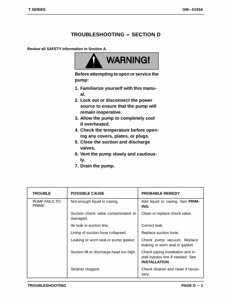
TROUBLESHOOTING --- SECTION D
Review all SAFETY information in Section A.
Before attempting to open or service thepump:
1. Familiarize yourself with this manu-al.
2. Lock out or disconnect the powersource to ensure that the pump willremain inoperative.
3. Allow the pump to completely coolif overheated.
4. Check the temperature before open-ing any covers, plates, or plugs.
5. Close the suction and dischargevalves.
6. Vent the pump slowly and cautious-ly.
7. Drain the pump.
TROUBLE POSSIBLE CAUSE PROBABLE REMEDY
PUMP FAILS TOPRIME
Suction check valve contaminated ordamaged.
Clean or replace check valve.
Air leak in suction line.
Lining of suction hose collapsed.
Correct leak.
Replace suction hose.
Leaking or worn seal or pump gasket. Check pump vacuum. Replaceleaking or worn seal or gasket.
Suction lift or discharge head too high. Check piping installation and in-stall bypass line if needed. SeeINSTALLATION.
Strainer clogged. Check strainer and clean if neces-sary.
Not enough liquid in casing. Add liquid to casing. See PRIM-ING.
OM--01934 T SERIES
TROUBLESHOOTINGPAGE D -- 2
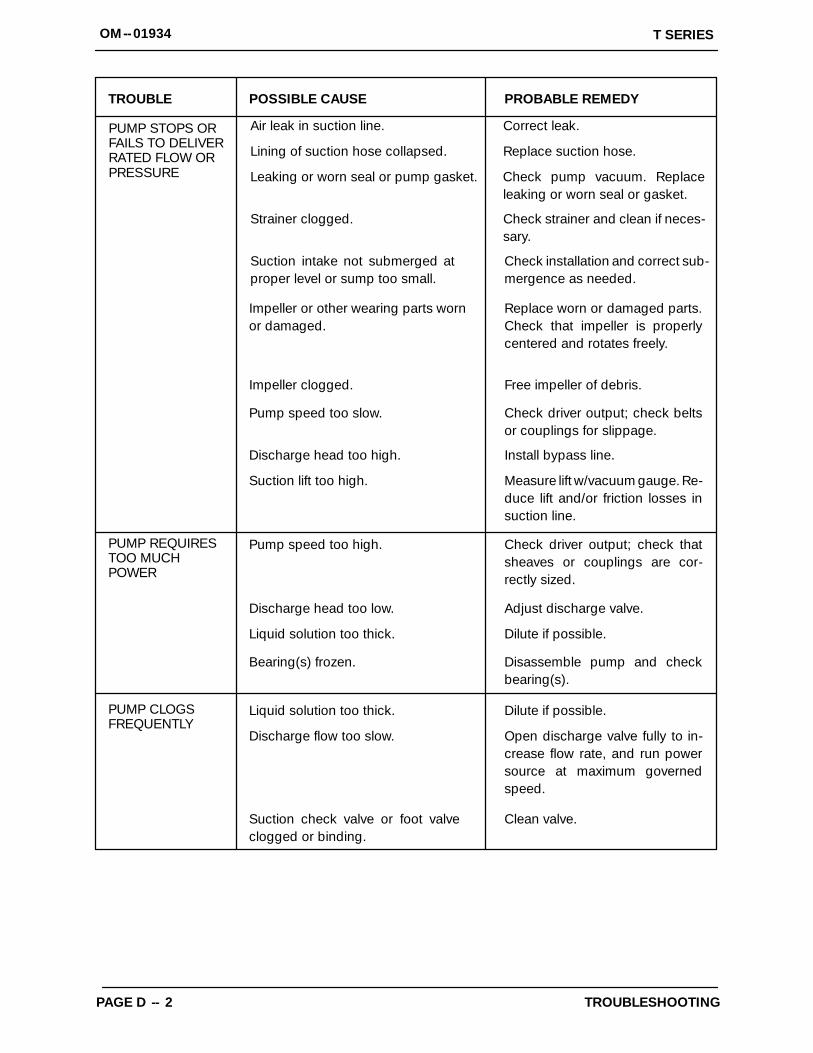
TROUBLE POSSIBLE CAUSE PROBABLE REMEDY
PUMP REQUIRESTOO MUCHPOWER
PUMP CLOGSFREQUENTLY
Impeller or other wearing parts wornor damaged.
Replace worn or damaged parts.Check that impeller is properlycentered and rotates freely.
Impeller clogged. Free impeller of debris.
Pump speed too slow. Check driver output; check beltsor couplings for slippage.
Discharge head too high. Install bypass line.
Suction lift too high. Measure lift w/vacuum gauge. Re-duce lift and/or friction losses insuction line.
Pump speed too high. Check driver output; check thatsheaves or couplings are cor-rectly sized.
Discharge head too low. Adjust discharge valve.
Liquid solution too thick. Dilute if possible.
Bearing(s) frozen. Disassemble pump and checkbearing(s).
Liquid solution too thick. Dilute if possible.
Discharge flow too slow. Open discharge valve fully to in-crease flow rate, and run powersource at maximum governedspeed.
Suction check valve or foot valveclogged or binding.
Clean valve.
PUMP STOPS ORFAILS TO DELIVERRATED FLOW ORPRESSURE
Air leak in suction line.
Lining of suction hose collapsed.
Correct leak.
Replace suction hose.
Leaking or worn seal or pump gasket. Check pump vacuum. Replaceleaking or worn seal or gasket.
Strainer clogged. Check strainer and clean if neces-sary.
Suction intake not submerged atproper level or sump too small.
Check installation and correct sub-mergence as needed.
T SERIES OM--01934
TROUBLESHOOTING PAGE D -- 3
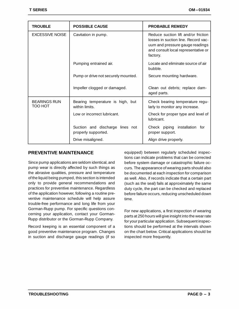
TROUBLE POSSIBLE CAUSE PROBABLE REMEDY
BEARINGS RUNTOO HOT
Bearing temperature is high, butwithin limits.
Check bearing temperature regu-larly to monitor any increase.
Low or incorrect lubricant. Check for proper type and level oflubricant.
Suction and discharge lines notproperly supported.
Check piping installation forproper support.
Drive misaligned. Align drive properly.
EXCESSIVE NOISE Cavitation in pump.
Impeller clogged or damaged.
Pump or drive not securely mounted.
Pumping entrained air.
Reduce suction lift and/or frictionlosses in suction line. Record vac-uum and pressure gauge readingsand consult local representative orfactory.
Locate and eliminate source of airbubble.
Secure mounting hardware.
Clean out debris; replace dam-aged parts.
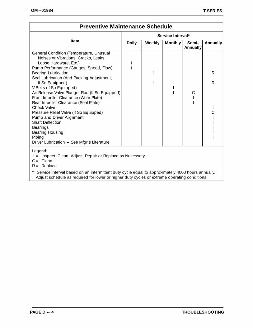
PREVENTIVE MAINTENANCE
Since pump applications are seldom identical, andpump wear is directly affected by such things asthe abrasive qualities, pressure and temperatureof the liquid being pumped, this section is intendedonly to provide general recommendations andpractices for preventive maintenance. Regardlessof the application however, following a routine pre-ventive maintenance schedule will help assuretrouble-free performance and long life from yourGorman-Rupp pump. For specific questions con-cerning your application, contact your Gorman-Rupp distributor or the Gorman-Rupp Company.
Record keeping is an essential component of agood preventive maintenance program. Changesin suction and discharge gauge readings (if so
equipped) between regularly scheduled inspec-tions can indicate problems that can be correctedbefore system damage or catastrophic failure oc-curs. The appearance of wearing parts should alsobe documented at each inspection for comparisonas well. Also, if records indicate that a certain part(such as the seal) fails at approximately the sameduty cycle, the part can be checked and replacedbefore failure occurs, reducing unscheduled downtime.
For new applications, a first inspection of wearingparts at 250 hours will give insight into the wear ratefor your particular application. Subsequent inspec-tions should be performed at the intervals shownon the chart below. Critical applications should beinspected more frequently.
OM--01934 T SERIES
TROUBLESHOOTINGPAGE D -- 4
General Condition (Temperature, UnusualNoises or Vibrations, Cracks, Leaks,Loose Hardware, Etc.) I
Pump Performance (Gauges, Speed, Flow) IBearing Lubrication I RSeal Lubrication (And Packing Adjustment,
If So Equipped) I RV-Belts (If So Equipped) IAir Release Valve Plunger Rod (If So Equipped) I CFront Impeller Clearance (Wear Plate) IRear Impeller Clearance (Seal Plate) ICheck Valve IPressure Relief Valve (If So Equipped) CPump and Driver Alignment IShaft Deflection IBearings IBearing Housing IPiping IDriver Lubrication --- See Mfgr’s Literature
Legend:I = Inspect, Clean, Adjust, Repair or Replace as Necessary
C = CleanR = Replace* Service interval based on an intermittent duty cycle equal to approximately 4000 hours annually.
Adjust schedule as required for lower or higher duty cycles or extreme operating conditions.
Preventive Maintenance Schedule
Item Daily Weekly Monthly Semi-Annually
Annually
Service Interval*
OM--01934T SERIES
MAINTENANCE & REPAIR PAGE E -- 1
PUMP MAINTENANCE AND REPAIR --- SECTION E
MAINTENANCE AND REPAIR OF THE WEARING PARTS OF THE PUMP WILL MAINTAIN PEAK OPER-ATING PERFORMANCE.
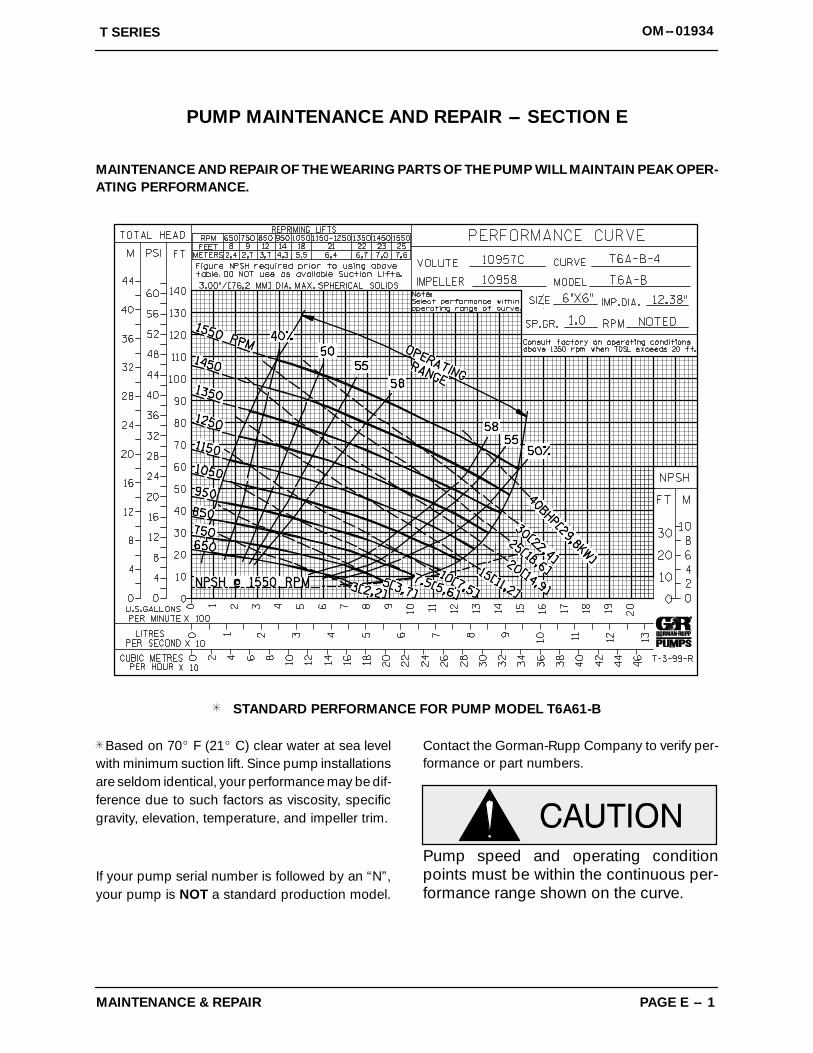
STANDARD PERFORMANCE FOR PUMP MODEL T6A61-B
Based on 70_ F (21_ C) clear water at sea levelwith minimum suction lift. Since pump installationsare seldom identical, your performance may be dif-ference due to such factors as viscosity, specificgravity, elevation, temperature, and impeller trim.
If your pump serial number is followed by an “N”,your pump is NOT a standard production model.
Contact the Gorman-Rupp Company to verify per-formance or part numbers.
Pump speed and operating conditionpoints must be within the continuous per-formance range shown on the curve.
OM--01934 T SERIES
MAINTENANCE & REPAIRPAGE E -- 2
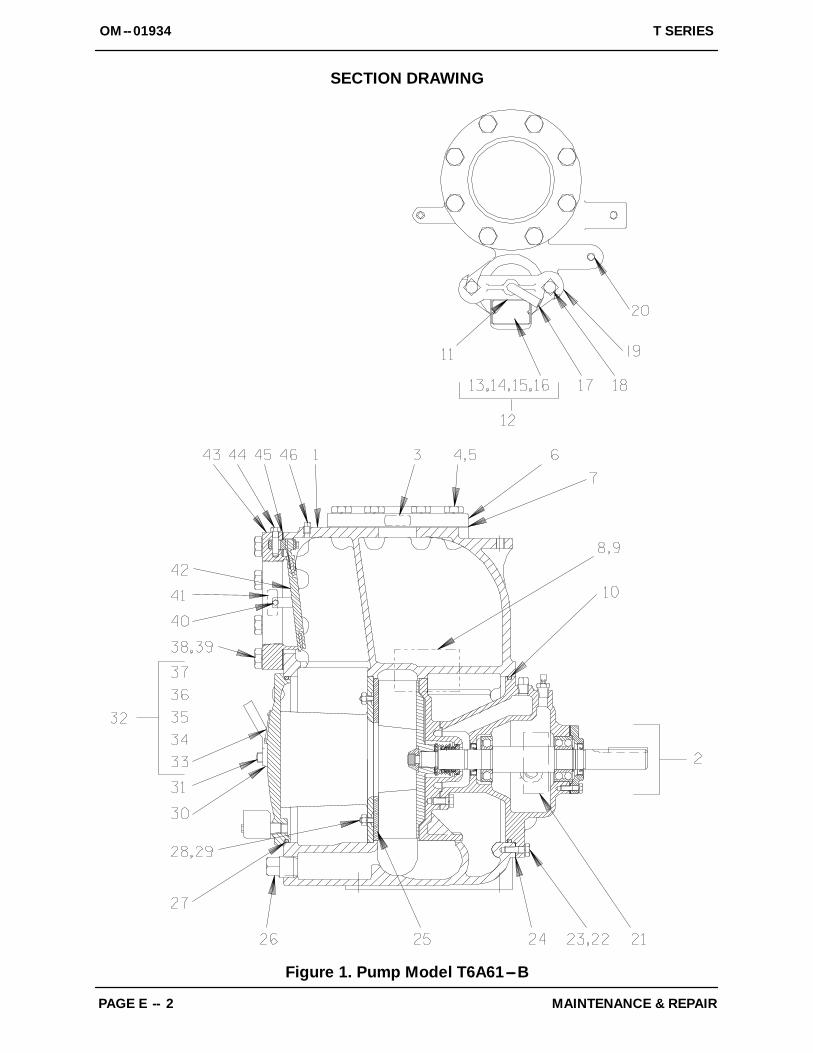
SECTION DRAWING
Figure 1. Pump Model T6A61---B
ITEMNO.
PART NAME PARTNUMBER
MAT’LCODE
QTY ITEMNO.
PART NAME PARTNUMBER
MAT’LCODE
QTY
OM--01934T SERIES
MAINTENANCE & REPAIR PAGE E -- 3
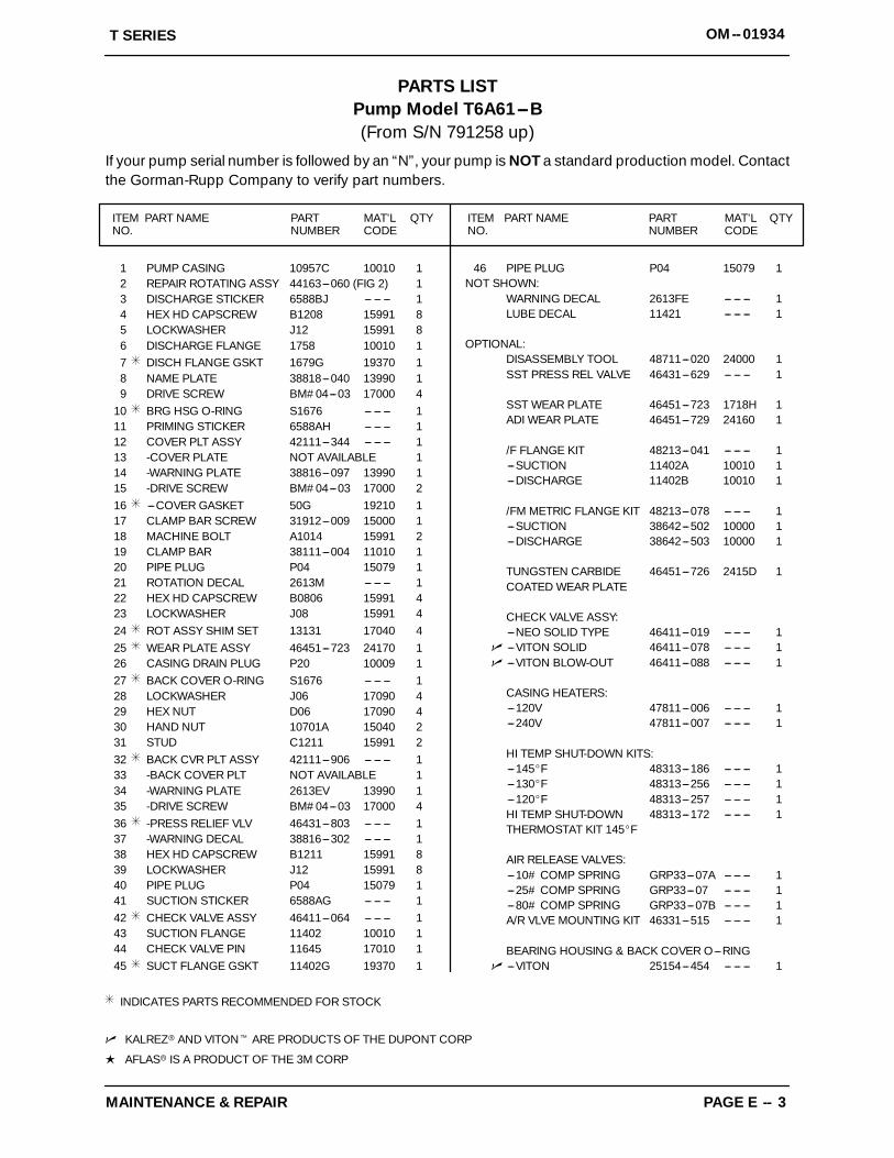
PARTS LISTPump Model T6A61---B(From S/N 791258 up)
If your pump serial number is followed by an “N”, your pump is NOT a standard production model. Contactthe Gorman-Rupp Company to verify part numbers.
1 PUMP CASING 10957C 10010 12 REPAIR ROTATING ASSY 44163---060 (FIG 2) 13 DISCHARGE STICKER 6588BJ --- --- --- 14 HEX HD CAPSCREW B1208 15991 85 LOCKWASHER J12 15991 86 DISCHARGE FLANGE 1758 10010 17 DISCH FLANGE GSKT 1679G 19370 18 NAME PLATE 38818---040 13990 19 DRIVE SCREW BM#04---03 17000 4
10 BRG HSG O-RING S1676 --- --- --- 111 PRIMING STICKER 6588AH --- --- --- 112 COVER PLT ASSY 42111---344 --- --- --- 113 -COVER PLATE NOT AVAILABLE 114 -WARNING PLATE 38816---097 13990 115 -DRIVE SCREW BM#04---03 17000 216 ---COVER GASKET 50G 19210 117 CLAMP BAR SCREW 31912---009 15000 118 MACHINE BOLT A1014 15991 219 CLAMP BAR 38111---004 11010 120 PIPE PLUG P04 15079 121 ROTATION DECAL 2613M --- --- --- 122 HEX HD CAPSCREW B0806 15991 423 LOCKWASHER J08 15991 424 ROT ASSY SHIM SET 13131 17040 425 WEAR PLATE ASSY 46451---723 24170 126 CASING DRAIN PLUG P20 10009 127 BACK COVER O-RING S1676 --- --- --- 128 LOCKWASHER J06 17090 429 HEX NUT D06 17090 430 HAND NUT 10701A 15040 231 STUD C1211 15991 232 BACK CVR PLT ASSY 42111---906 --- --- --- 133 -BACK COVER PLT NOT AVAILABLE 134 -WARNING PLATE 2613EV 13990 135 -DRIVE SCREW BM#04---03 17000 436 -PRESS RELIEF VLV 46431---803 --- --- --- 137 -WARNING DECAL 38816---302 --- --- --- 138 HEX HD CAPSCREW B1211 15991 839 LOCKWASHER J12 15991 840 PIPE PLUG P04 15079 141 SUCTION STICKER 6588AG --- --- --- 142 CHECK VALVE ASSY 46411---064 --- --- --- 143 SUCTION FLANGE 11402 10010 144 CHECK VALVE PIN 11645 17010 145 SUCT FLANGE GSKT 11402G 19370 1
46 PIPE PLUG P04 15079 1NOT SHOWN:
WARNING DECAL 2613FE --- --- --- 1LUBE DECAL 11421 --- --- --- 1
OPTIONAL:DISASSEMBLY TOOL 48711---020 24000 1SST PRESS REL VALVE 46431---629 --- --- --- 1
SST WEAR PLATE 46451---723 1718H 1ADI WEAR PLATE 46451---729 24160 1
/F FLANGE KIT 48213---041 --- --- --- 1---SUCTION 11402A 10010 1---DISCHARGE 11402B 10010 1
/FM METRIC FLANGE KIT 48213---078 --- --- --- 1---SUCTION 38642---502 10000 1---DISCHARGE 38642---503 10000 1
TUNGSTEN CARBIDE 46451---726 2415D 1COATED WEAR PLATE
CHECK VALVE ASSY:---NEO SOLID TYPE 46411---019 --- --- --- 1
n ---VITON SOLID 46411---078 --- --- --- 1n ---VITON BLOW-OUT 46411---088 --- --- --- 1
CASING HEATERS:---120V 47811---006 --- --- --- 1---240V 47811---007 --- --- --- 1
HI TEMP SHUT-DOWN KITS:---145_F 48313---186 --- --- --- 1---130_F 48313---256 --- --- --- 1---120_F 48313---257 --- --- --- 1HI TEMP SHUT-DOWN 48313---172 --- --- --- 1THERMOSTAT KIT 145_F
AIR RELEASE VALVES:---10# COMP SPRING GRP33---07A --- --- --- 1---25# COMP SPRING GRP33---07 --- --- --- 1---80# COMP SPRING GRP33---07B --- --- --- 1A/R VLVE MOUNTING KIT 46331---515 --- --- --- 1
BEARING HOUSING & BACK COVER O---RINGn ---VITON 25154---454 --- --- --- 1
INDICATES PARTS RECOMMENDED FOR STOCK
n KALREZr AND VITONt ARE PRODUCTS OF THE DUPONT CORP
L AFLASr IS A PRODUCT OF THE 3M CORP
OM--01934 T SERIES
MAINTENANCE & REPAIRPAGE E -- 4
SECTION DRAWING
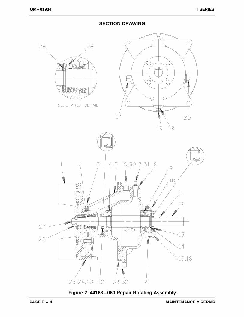
Figure 2. 44163---060 Repair Rotating Assembly
ITEMNO.
PART NAME PARTNUMBER
MAT’LCODE
QTY ITEMNO.
PART NAME PARTNUMBER
MAT’LCODE
QTY
OM--01934T SERIES
MAINTENANCE & REPAIR PAGE E -- 5
PARTS LIST44163---060 Repair Rotating Assembly
1 IMPELLER 10958 17070 12 SEAL ASSEMBLY 46512---047 --- --- --- 13 SEAL PLATE GSKT 10959G 20000 14 BALL BEARING 23276---009 --- --- --- 15 BEARING HOUSING 10959B 10010 16 VENTED SEAL PLUG 4823A 15079 17 HOUSING AIR VENT S1530 --- --- --- 18 REDUCER BUSHING AP0802 15079 19 BALL BEARING S1040 --- --- --- 1
10 BEARING CAP 38322---215 10010 111 IMPELLER SHAFT 10529B 1706H 112 IMPELLER SHAFT KEY N0612 15990 113 OIL SEAL S1352 --- --- --- 114 SNAP RING S244 --- --- --- 115 HEX HD CAPSCREW B0605 15991 416 LOCKWASHER J06 15991 417 PIPE PLUG P12 15079 118 BRG CVTY DRAIN PLUG P08 15079 119 SEAL CVTY DRAIN PLUG P08 15079 120 OIL SIGHT GAUGE S1471 --- --- --- 121 BEARING CAP GSKT 38683---248 18000 122 OIL SEAL S1352 --- --- --- 123 HEX HD CAPSCREW B0805 1/2 17000 424 LOCKWASHER J08 17090 425 SEAL PLATE 11837E 17070 126 IMPELLER WASHER 10278 17090 127 IMPELLER CAPSCREW DM1004S 17090 128 IMPELLER SHIM SET 37J 17090 REF29 SEAL WASHER 38329---040 17130 130 SHIPPING PLUG 11495B 15079 1
31 SHIPPING PLUG 11495B 15079 132 SHIM SET 13131 17040 433 BRG HOUSING O-RING S1676 --- --- --- 1
NOT SHOWN:ROTATION DECAL 2613M --- --- --- 1INSTRUCTION TAG 6588U --- --- --- 1
OPTIONAL:TUNGSTEN CARBIDE 10958A 1101D 1COATED IMPELLERSPA ALLOY IMP 10958 15014 1ADI IMPELLER 10958 1102H 1ADI WEAR PLATE 46451---729 24160 1ADI SEAL PLATE 11837E 1102H 1
IMP CLEAN---OUT KIT 48783---003 --- --- --- 1
ASTL WEAR PLATE 46451---729 24160 1
SEALS:---PERMALON COATED 46512---150 --- --- --- 1
[ L ---AFLAS (W/SLEEVE ORSOLID SST SHAFT 46512---194 --- --- --- 1
---SST SEAL PLATE 38272---242 1718H 1
ROTATING ASSY O---RINGSn ---VITON 25154---454 --- --- --- 1
[ METAL BELLOWS MECH SEAL ASSYn (VITON OR EQUAL) 46512---147 --- --- --- 1n (KALREZ) 46512---142 --- --- --- 1
INDICATES PARTS RECOMMENDED FOR STOCK
FOR PUMPS WITH SERIAL NUMBERS BELOW 864836, ORDER 10530G/18000 BEARING CAP GASKET.
IF BOTH BEARING CAP AND GASKET MUST BE REPLACED, ORDER PARTS LISTED ABOVE.
[ OPTIONAL MECHANICAL SEAL(S) MUST BE USED WITH MECHANICAL SEAL SHAFT SLEEVE OR SOLID SST SHAFT.
n KALREZr AND VITONt ARE PRODUCTS OF THE DUPONT CORP
L AFLASr IS A PRODUCT OF THE 3M CORP
OM--01934 T SERIES
MAINTENANCE & REPAIRPAGE E -- 6
PUMP AND SEAL DISASSEMBLYAND REASSEMBLY
Review all SAFETY information in Section A.
Follow the instructions on all tags, label and decalsattached to the pump.
This pump requires little service due to its rugged,minimum-maintenance design. However, if it be-comes necessary to inspect or replace the wearingparts, follow these instructions which are keyed tothe sectional views (see Figures 1 and 2) and theaccompanying parts lists.
As described on the following page, this manualwill alert personnel to known procedures which re-quire special attention, to those which could dam-age equipment, and to those which could be dan-gerous to personnel. However, this manual cannotpossibly anticipate and provide detailed precau-tions for every situation that might occur duringmaintenance of the unit. Therefore, it is the respon-sibility of the owner/maintenance personnel to en-sure that only safe, established maintenance pro-cedures are used, and that any procedures not ad-dressed in this manual are performed only after es-tablishing that neither personal safety nor pump in-tegrity are compromised by such practices.
Many service functions may be performed bydraining the pump and removing the back coverassembly. If major repair is required, the pipingand/or power source must be disconnected. Thefollowing instructions assume complete disassem-bly is required.
Before attempting to service the pump, disconnector lock out the power source and take precautionsto ensure that it will remain inoperative. Close allvalves in the suction and discharge lines.
For power source disassembly and repair, consultthe literature supplied with the power source, orcontact your local power source representative.
Before attempting to open or service thepump:
1. Familiarize yourself with this man-ual.
2. Disconnect or lock out the powersource to ensure that the pump willremain inoperative.
3. Allow the pump to completely coolif overheated.
4. Check the temperature beforeopening any covers, plates, orplugs.
5. Close the suction and dischargevalves.
6. Vent the pump slowly and cau-tiously.
7. Drain the pump.
Use lifting and moving equipment ingood repair and with adequate capacityto prevent injuries to personnel or dam-age to equipment.
Back Cover And Wear Plate Removal
(Figure 1)
The wear plate (25) is easily accessible and may beserviced by removing the back cover assembly(32). Before attempting to service the pump, re-move the pump casing drain plug (26) and drainthe pump. Clean and reinstall the drain plug.
Remove the hand nuts (30) and pull the back coverand assembled wear plate from the pump casing(1). Inspect the wear plate, and replace it if badlyscored or worn. To remove the wear plate, disen-gage the hardware (28 and 29).
Inspect the back cover O-ring (27) and replace it ifdamaged or worn.
Suction Check Valve Removal
(Figure 1)
If the check valve assembly (42) is to be serviced,remove the check valve pin (44), reach through theback cover opening and pull the complete assem-bly from the suction flange (43).
NOTEFurther disassembly of the check valve is not re-
OM--01934T SERIES
MAINTENANCE & REPAIR PAGE E -- 7
quired since it must be replaced as a complete unit.Individual parts are not sold separately.
Rotating Assembly Removal
(Figure 2)
The rotating assembly may be serviced withoutdisconnecting the suction or discharge piping;however, the power source must be removed toprovide clearance.
The impeller (1) should be loosened while the rotat-ing assembly is still secured to the pump casing.Before loosening the impeller, remove the seal cav-ity drain plug (19) and drain the seal lubricant. Thiswill prevent the oil in the seal cavity from escapingwhen the impeller is loosened. Clean and reinstallthe seal cavity drain plug.
Immobilize the impeller by wedging a block woodbetween the vanes and the pump casing, and re-move the impeller capscrew and washer (26 and27).
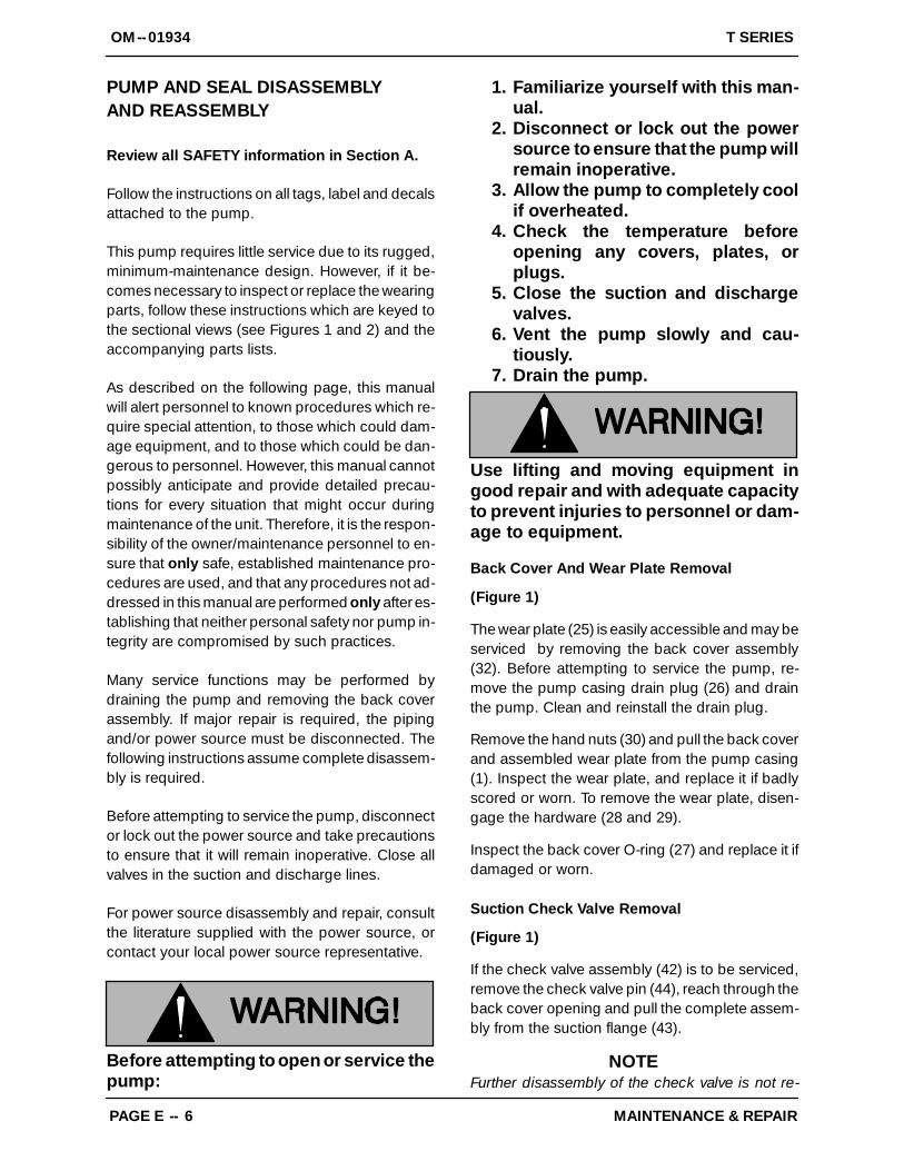
Install a lathe dog on the drive end of the shaft (11)with the “V” notch positioned over the shaft key-way.
With the impeller rotation still blocked, see Figure 3and use a long piece of heavy bar stock to pryagainst the arm of the lathe dog in a counterclock-wise direction (when facing the drive end of theshaft). Use caution not to damage the shaft or key-way. When the impeller breaks loose, remove thelathe dog and wood block.
NOTEDo not remove the impeller until the rotating assem-bly has been removed from the pump casing.
TurnCounterclockwise
Lathe Dog Arm
“V” Notch
Shaft Key
Impeller Shaft
Lathe Dog
Setscrew
HeavyBar Stock
Figure 3. Loosening Impeller
(Figure 1)
Remove the hardware (22 and 23) securing the ro-tating assembly to the pump casing. Separate therotating assembly by pulling straight away from thepump casing.
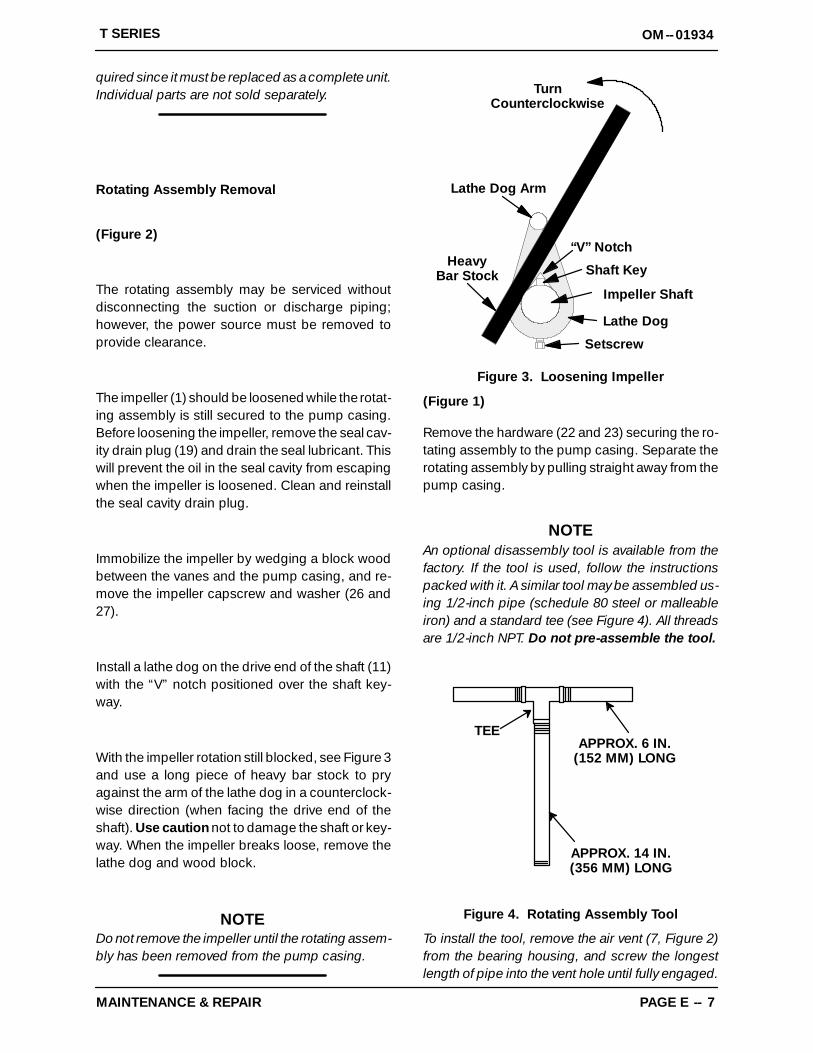
NOTEAn optional disassembly tool is available from thefactory. If the tool is used, follow the instructionspacked with it. A similar tool may be assembled us-ing 1/2-inch pipe (schedule 80 steel or malleableiron) and a standard tee (see Figure 4). All threadsare 1/2-inch NPT. Do not pre-assemble the tool.
TEEAPPROX. 6 IN.
(152 MM) LONG
APPROX. 14 IN.(356 MM) LONG
Figure 4. Rotating Assembly Tool
To install the tool, remove the air vent (7, Figure 2)from the bearing housing, and screw the longestlength of pipe into the vent hole until fully engaged.
OM--01934 T SERIES
MAINTENANCE & REPAIRPAGE E -- 8
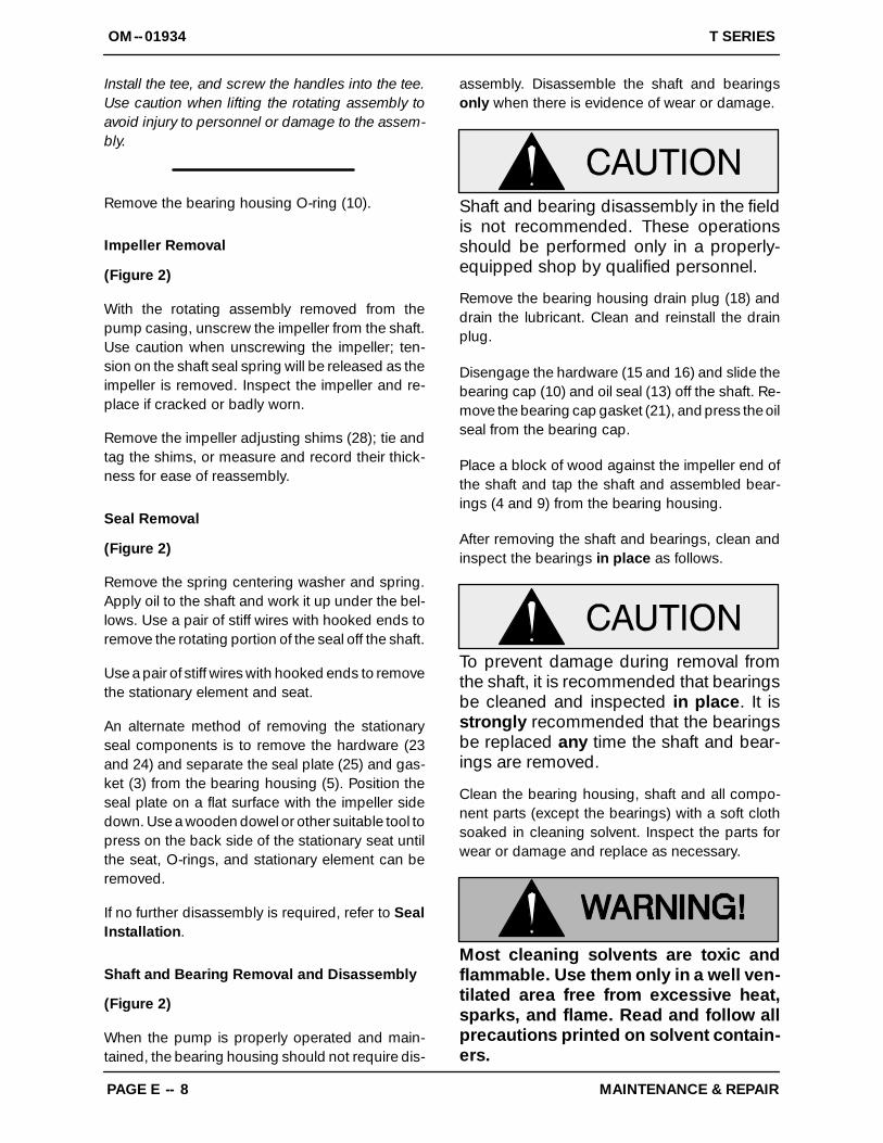
Install the tee, and screw the handles into the tee.Use caution when lifting the rotating assembly toavoid injury to personnel or damage to the assem-bly.
Remove the bearing housing O-ring (10).
Impeller Removal
(Figure 2)
With the rotating assembly removed from thepump casing, unscrew the impeller from the shaft.Use caution when unscrewing the impeller; ten-sion on the shaft seal spring will be released as theimpeller is removed. Inspect the impeller and re-place if cracked or badly worn.
Remove the impeller adjusting shims (28); tie andtag the shims, or measure and record their thick-ness for ease of reassembly.
Seal Removal
(Figure 2)
Remove the spring centering washer and spring.Apply oil to the shaft and work it up under the bel-lows. Use a pair of stiff wires with hooked ends toremove the rotating portion of the seal off the shaft.
Use a pair of stiff wires with hooked ends to removethe stationary element and seat.
An alternate method of removing the stationaryseal components is to remove the hardware (23and 24) and separate the seal plate (25) and gas-ket (3) from the bearing housing (5). Position theseal plate on a flat surface with the impeller sidedown. Use a wooden dowel or other suitable tool topress on the back side of the stationary seat untilthe seat, O-rings, and stationary element can beremoved.
If no further disassembly is required, refer to SealInstallation.
Shaft and Bearing Removal and Disassembly
(Figure 2)
When the pump is properly operated and main-tained, the bearing housing should not require dis-
assembly. Disassemble the shaft and bearingsonly when there is evidence of wear or damage.
Shaft and bearing disassembly in the fieldis not recommended. These operationsshould be performed only in a properly-equipped shop by qualified personnel.
Remove the bearing housing drain plug (18) anddrain the lubricant. Clean and reinstall the drainplug.
Disengage the hardware (15 and 16) and slide thebearing cap (10) and oil seal (13) off the shaft. Re-move the bearing cap gasket (21), and press the oilseal from the bearing cap.
Place a block of wood against the impeller end ofthe shaft and tap the shaft and assembled bear-ings (4 and 9) from the bearing housing.
After removing the shaft and bearings, clean andinspect the bearings in place as follows.
To prevent damage during removal fromthe shaft, it is recommended that bearingsbe cleaned and inspected in place. It isstrongly recommended that the bearingsbe replaced any time the shaft and bear-ings are removed.
Clean the bearing housing, shaft and all compo-nent parts (except the bearings) with a soft clothsoaked in cleaning solvent. Inspect the parts forwear or damage and replace as necessary.
Most cleaning solvents are toxic andflammable. Use them only in a well ven-tilated area free from excessive heat,sparks, and flame. Read and follow allprecautions printed on solvent contain-ers.
OM--01934T SERIES
MAINTENANCE & REPAIR PAGE E -- 9
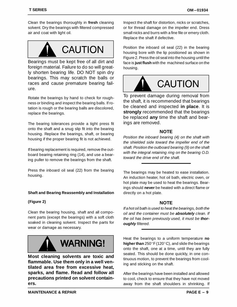
Clean the bearings thoroughly in fresh cleaningsolvent. Dry the bearings with filtered compressedair and coat with light oil.
Bearings must be kept free of all dirt andforeign material. Failure to do so will great-ly shorten bearing life. DO NOT spin drybearings. This may scratch the balls orraces and cause premature bearing fail-ure.
Rotate the bearings by hand to check for rough-ness or binding and inspect the bearing balls. If ro-tation is rough or the bearing balls are discolored,replace the bearings.
The bearing tolerances provide a tight press fitonto the shaft and a snug slip fit into the bearinghousing. Replace the bearings, shaft, or bearinghousing if the proper bearing fit is not achieved.
If bearing replacement is required, remove the out-board bearing retaining ring (14), and use a bear-ing puller to remove the bearings from the shaft.
Press the inboard oil seal (22) from the bearinghousing.
Shaft and Bearing Reassembly and Installation
(Figure 2)
Clean the bearing housing, shaft and all compo-nent parts (except the bearings) with a soft clothsoaked in cleaning solvent. Inspect the parts forwear or damage as necessary.
Most cleaning solvents are toxic andflammable. Use them only in a well ven-tilated area free from excessive heat,sparks, and flame. Read and follow allprecautions printed on solvent contain-ers.
Inspect the shaft for distortion, nicks or scratches,or for thread damage on the impeller end. Dresssmall nicks and burrs with a fine file or emery cloth.Replace the shaft if defective.
Position the inboard oil seal (22) in the bearinghousing bore with the lip positioned as shown inFigure 2. Press the oil seal into the housing until theface is just flush with the machined surface on thehousing.
To prevent damage during removal fromthe shaft, it is recommended that bearingsbe cleaned and inspected in place. It isstrongly recommended that the bearingsbe replaced any time the shaft and bear-ings are removed.
NOTEPosition the inboard bearing (4) on the shaft withthe shielded side toward the impeller end of theshaft. Position the outboard bearing (9) on the shaftwith the integral retaining ring on the bearing O.D.toward the drive end of the shaft.
The bearings may be heated to ease installation.An induction heater, hot oil bath, electric oven, orhot plate may be used to heat the bearings. Bear-ings should never be heated with a direct flame ordirectly on a hot plate.
NOTEIf a hot oil bath is used to heat the bearings, both theoil and the container must be absolutely clean. Ifthe oil has been previously used, it must be thor-oughly filtered.
Heat the bearings to a uniform temperature nohigher than 250_F (120_C), and slide the bearingsonto the shaft, one at a time, until they are fullyseated. This should be done quickly, in one con-tinuous motion, to prevent the bearings from cool-ing and sticking on the shaft.
After the bearings have been installed and allowedto cool, check to ensure that they have not movedaway from the shaft shoulders in shrinking. If
OM--01934 T SERIES
MAINTENANCE & REPAIRPAGE E -- 10
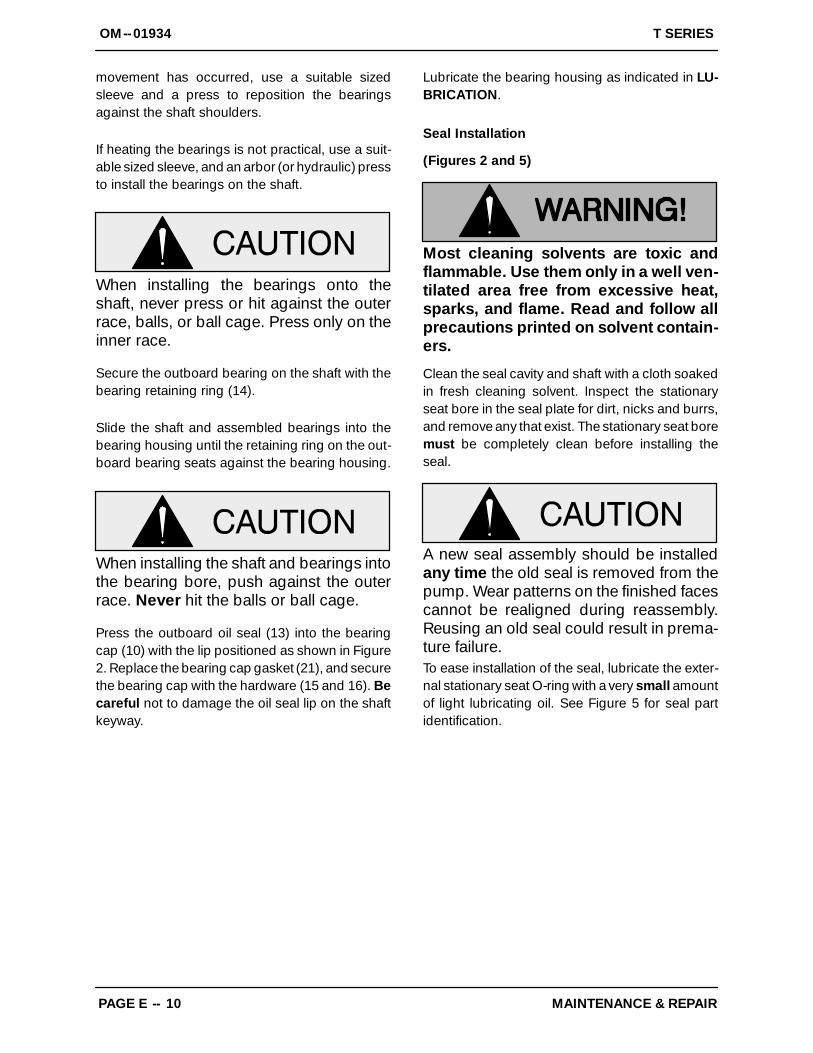
movement has occurred, use a suitable sizedsleeve and a press to reposition the bearingsagainst the shaft shoulders.
If heating the bearings is not practical, use a suit-able sized sleeve, and an arbor (or hydraulic) pressto install the bearings on the shaft.
When installing the bearings onto theshaft, never press or hit against the outerrace, balls, or ball cage. Press only on theinner race.
Secure the outboard bearing on the shaft with thebearing retaining ring (14).
Slide the shaft and assembled bearings into thebearing housing until the retaining ring on the out-board bearing seats against the bearing housing.
When installing the shaft and bearings intothe bearing bore, push against the outerrace. Never hit the balls or ball cage.
Press the outboard oil seal (13) into the bearingcap (10) with the lip positioned as shown in Figure2. Replace the bearing cap gasket (21), and securethe bearing cap with the hardware (15 and 16). Becareful not to damage the oil seal lip on the shaftkeyway.
Lubricate the bearing housing as indicated in LU-BRICATION.
Seal Installation
(Figures 2 and 5)
Most cleaning solvents are toxic andflammable. Use them only in a well ven-tilated area free from excessive heat,sparks, and flame. Read and follow allprecautions printed on solvent contain-ers.
Clean the seal cavity and shaft with a cloth soakedin fresh cleaning solvent. Inspect the stationaryseat bore in the seal plate for dirt, nicks and burrs,and remove any that exist. The stationary seat boremust be completely clean before installing theseal.
A new seal assembly should be installedany time the old seal is removed from thepump. Wear patterns on the finished facescannot be realigned during reassembly.Reusing an old seal could result in prema-ture failure.To ease installation of the seal, lubricate the exter-nal stationary seat O-ring with a very small amountof light lubricating oil. See Figure 5 for seal partidentification.
OM--01934T SERIES
MAINTENANCE & REPAIR PAGE E -- 11
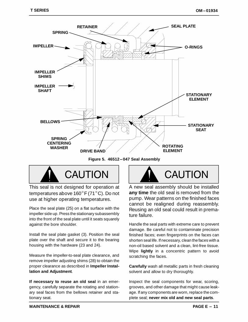
SEAL PLATE
O-RINGS
IMPELLERSHAFT
STATIONARYSEAT
STATIONARYELEMENT
ROTATINGELEMENTDRIVE BAND
BELLOWS
IMPELLERSHIMS
IMPELLER
SPRINGRETAINER
SPRINGCENTERING
WASHER
Figure 5. 46512--047 Seal Assembly
This seal is not designed for operation attemperatures above 160_F (71_C). Do notuse at higher operating temperatures.
Place the seal plate (25) on a flat surface with theimpeller side up. Press the stationary subassemblyinto the front of the seal plate until it seats squarelyagainst the bore shoulder.
Install the seal plate gasket (3). Position the sealplate over the shaft and secure it to the bearinghousing with the hardware (23 and 24).
Measure the impeller-to-seal plate clearance, andremove impeller adjusting shims (28) to obtain theproper clearance as described in Impeller Instal-lation and Adjustment.
If necessary to reuse an old seal in an emer-gency, carefully separate the rotating and station-ary seal faces from the bellows retainer and sta-tionary seat.
A new seal assembly should be installedany time the old seal is removed from thepump. Wear patterns on the finished facescannot be realigned during reassembly.Reusing an old seal could result in prema-ture failure.
Handle the seal parts with extreme care to preventdamage. Be careful not to contaminate precisionfinished faces; even fingerprints on the faces canshorten seal life. If necessary, clean the faces with anon-oil based solvent and a clean, lint-free tissue.Wipe lightly in a concentric pattern to avoidscratching the faces.
Carefully wash all metallic parts in fresh cleaningsolvent and allow to dry thoroughly.
Inspect the seal components for wear, scoring,grooves, and other damage that might cause leak-age. If any components are worn, replace the com-plete seal; never mix old and new seal parts.
OM--01934 T SERIES
MAINTENANCE & REPAIRPAGE E -- 12
Install the stationary seal element in the stationaryseat. Press this stationary subassembly into theseal plate bore until it seats squarely against thebore shoulder. A push tube made from a piece ofplastic pipe would aid this installation. The I.D. ofthe pipe should be slightly larger than the O.D. ofthe shaft sleeve.
Slide the rotating portion of the seal (consisting ofthe spring centering washer, spring, bellows andretainer, and rotating element) onto the shaft untilthe seal faces contact.
Proceed with Impeller Installation and Adjust-ment.
Impeller Installation
(Figure 2)
Inspect the impeller, and replace it if cracked orbadly worn. Inspect the impeller and shaft threadsfor dirt or damage, and clean or dress the threadsas required.
The shaft and impeller threads must becompletely clean before reinstalling the im-peller. Even the slightest amount of dirt onthe threads can cause the impeller to seizeto the shaft, making future removal difficultor impossible without damage to the im-peller or shaft.
Install the same thickness of impeller adjustingshims (28) as previously removed. Apply ‘Never-Seez’ or equivalent to the shaft threads and screwthe impeller onto the shaft until tight.
NOTEAt the slightest sign of binding, immediately backthe impeller off, and check the threads for dirt. Donot try to force the impeller onto the shaft.
A clearance of .025 to .040 inch (0,64 to 1,02 mm)between the impeller and the seal plate is recom-mended for maximum pump efficiency. Measurethis clearance, and add or remove impeller adjust-ing shims as required.
NOTEIf the rotating assembly has been installed in thepump casing, this clearance may be measured byreaching through the priming port with a feelergauge.
NOTEProceed with Rotating Assembly Installation be-fore installing the impeller capscrew and washer(26 and 27). The rotating assembly must be in-stalled in the pump casing in order to torque the im-peller capscrew.
After the rotating assembly is installed in the pumpcasing, coat the threads of the impeller capscrew(27) with ‘Never-Seez’ or equivalent compound,and install the impeller washer (26) and capscrew;torque the capscrew to 90 ft. lbs. (1080 in. lbs. or12,4 m. kg.).
Rotating Assembly Installation
(Figure 1)
NOTEIf the pump has been completely disassembled, itis recommended that the suction check valve andback cover assembly be reinstalled at this point.The back cover assembly must be in place to adjustthe impeller face clearance.
Install the bearing housing O-ring (10) and lubri-cate it with light grease. Ease the rotating assem-bly into the pump casing using the installation tool.Be careful not to damage the O-ring.
Install an the four sets of rotating assembly adjust-ing shims (24) using the same thickness as pre-viously removed. Secure the rotating assembly tothe pump casing with the hardware (22 and 23).Do not fully tighten the capscrews until the backcover has been reinstalled and the impeller faceclearance has been set.
A clearance of .010 to .020 inch (0,25 to 0,51 mm)between the impeller and the wear plate is also rec-ommended for maximum pump efficiency. Thisclearance can be obtained by removing an equalamount of shims from each rotating assemblyshim set until the impeller scrapes against the wearplate when the shaft is turned. After the impeller
OM--01934T SERIES
MAINTENANCE & REPAIR PAGE E -- 13
scrapes, add approximately .015 inch (0,4 mm) ofshims to each shim set.
NOTEAn alternate method of adjusting this clearance is toreach through the suction port with a feeler gaugeand measure the gap. Add or subtract rotating as-sembly shims accordingly.
Suction Check Valve Installation
(Figure 1)
Inspect the check valve assembly (42), and re-place it if badly worn.
NOTEThe check valve assembly must be replaced as acomplete unit. Individual parts are not sold sepa-rately.
Reach through the back cover opening with thecheck valve (42), and position the check valveadaptor in the mounting slot in the suction flange(43). Align the adaptor with the flange hole, and se-cure the assembly with the check valve pin (44).
NOTEIf the suction or discharge flanges were removed,replace the respective gaskets, apply ‘PermatexAviation No. 3 Form-A-Gasket’ or equivalent com-pound to the mating surfaces, and secure them tothe pump casing with the attaching hardware.
Back Cover Installation
(Figure 1)
If the wear plate (25) was removed for replace-ment, carefully center it on the back cover and se-cure it with the hardware (28 and 29). The wearplate must be concentric to prevent binding whenthe back cover is installed.
Replace the back cover O-ring (27), and lubricate itwith a generous amount of No. 2 grease. Clean anyscale or debris from the contacting surfaces in thepump casing that might interfere or prevent a goodseal with the back cover. Slide the back cover as-
sembly into the pump casing. Be sure the wearplate does not bind against the impeller.
NOTETo ease future disassembly, apply a film of greaseor ‘Never-Seez’ on the back cover shoulder, or anysurface which contacts the pump casing. This ac-tion will reduce rust and scale build-up.
Secure the back cover assembly by tightening thehand nuts (30) evenly. Do not over-tighten thehand nuts; they should be just tight enough to en-sure a good seal at the back cover shoulder. Besure the wear plate does not bind against the cas-ing.
PRESSURE RELIEF VALVEMAINTENANCE
(Figure 1)
The back cover is equipped with a pressure reliefvalve (36) to provide additional safety for the pumpand operator (refer to Liquid Temperature AndOverheating in OPERATION).
It is recommended that the pressure relief valve as-sembly be replaced at each overhaul, or any timethe pump overheats and activates the valve. Neverreplace this valve with a substitute which has notbeen specified or provided by the Gorman-RuppCompany.
Periodically, the valve should be removed for in-spection and cleaning. When reinstalling the reliefvalve, apply ‘Loctite Pipe Sealant With Teflon No.592’, or equivalent compound, on the relief valvethreads. Position the valve as shown in Figure 1with the discharge port pointing down.
Final Pump Assembly
(Figure 1)
Install the shaft key (12, Figure 2) and reconnectthe power source. Be sure to install any guardsused over the rotating members.
Do not operate the pump without the
OM--01934 T SERIES
MAINTENANCE & REPAIRPAGE E -- 14
guards in place over the rotating parts.Exposed rotating parts can catch cloth-ing, fingers, or tools, causing severe in-jury to personnel.
Install the suction and discharge lines and open allvalves. Make certain that all piping connections aretight, properly supported and secure.
Be sure the pump and power source have beenproperly lubricated, see LUBRICATION.
Remove the fill cover assembly (12) and fill thepump casing with clean liquid. Reinstall the fillcover and tighten it. Refer to OPERATION, SectionC, before putting the pump back into service.
LUBRICATION
Seal Assembly
(Figure 2)
Before starting the pump, remove the vented plug(6) and fill the seal cavity with approximately 40ounces (1,4 liters) of SAE No. 30 non-detergent oil,or to a level just below the tapped vented plug hole.Clean and reinstall the vented plug. Maintain the oilat this level.
Bearings
(Figure 2)
The bearing housing was fully lubricated whenshipped from the factory. Check the oil level regu-larly through the sight gauge (20)and maintain it at
the middle of the gauge. When lubrication is re-quired, add SAE No. 30 non-detergent oil throughthe hole for the air vent (7). Do not over-lubricate.Over-lubrication can cause the bearings to over-heat, resulting in premature bearing failure.
NOTEThe white reflector in the sight gauge must be posi-tioned horizontally to provide proper drainage.
Under normal conditions, drain the bearing hous-ing once each year and refill with approximately 32ounces (1 liter) clean oil. Change the oil more fre-quently if the pump is operated continuously or in-stalled in an environment with rapid temperaturechange.
Monitor the condition of the bearing lubri-cant regularly for evidence of rust or mois-ture condensation. This is especially im-portant in areas where variable hot andcold temperatures are common.
For cold weather operation, consult the factory or alubricant supplier for the recommended grade ofoil.
Power Source
Consult the literature supplied with the powersource, or contact your local power source repre-sentative.

For U.S. and International Warranty Information,Please Visit www.grpumps.com/warranty
or call:U.S.: 419−755−1280
International: +1−419−755−1352
For Canadian Warranty Information,Please Visit www.grcanada.com/warranty
or call:519−631−2870
THE GORMAN-RUPP COMPANY � MANSFIELD, OHIOGORMAN-RUPP OF CANADA LIMITED � ST. THOMAS, ONTARIO, CANADA