Embed Size (px)
Citation preview
OM245
P2171-OM-390 R4
Installation, Operation and Maintenance Manual
for the
Kinergetics HCU 3/4 - HCU 3/6 System(Habitat Conditioning Units)
(Part No: KI40037 & KI40034)
A part of

(Intentionally Blank)

OM245 iP2171-OM-390 R4 Approval Sheet
Approval Sheet
This document is produced and controlled by Divex Ltd, Enterprise Drive, Westhill, Aberdeen,Scotland, AB32 6TQ; Tel: +44(0)1224 740145; email:[email protected]
It may not be communicated to a third party in part or whole without the prior written permission ofDivex.
Divex
Manual Number: OM245
Advitium Number: P2171-OM-390
Document Title: Installation, operating & maintenance manual for the Kinergetics HCU 3/4 - HCU 3/6 System (Habitat Conditioning Units)
Rev Date By Check App Comments
0 16 October 2001 P. Buchan John Rendall Fred Pope Original Issue
1 19 December 2001 P. Buchan Fred Pope Fred Pope ECN: 3670
2 2 November 2005 Christine Bain James Massie James Massie ECN: 6038
3 13 May 2009 Alison Middleton Eliot Aitken Ray Wylie ECN: 12445
4 29 January 2014 Debbie Allan Vladimir Garzon Steven Coull ECN: 16264
5
6
7
Original Issue Date: 16 October 2001
Original Document By: P. Buchan
Checked By: John Rendall
Approved By: Fred Pope

ii OM245Approval Sheet P2171-OM-390 R4
(Intentionally Blank)

OM245 iiiP2171-OM-390 R4 Table of Contents
Table of Contents
Page
Chapter 1 - General Description .......................................................................................................1
Chapter 2 - Initial Set Up ...................................................................................................................7
Chapter 3 - Operation Instructions ..................................................................................................13
Chapter 4 - Maintenance & Repair .................................................................................................19

iv OM245Table of Contents P2171-OM-390 R4
(Intentionally Blank)

OM245 1P2171-OM-390 R4 Chapter 1
Chapter 1 - General Description
Contents
Page
1.1 General Specifications ...................................................................................................... 21.1.1 Habitat Conditioning Unit .................................................................................................. 2
1.2 Warranty ........................................................................................................................... 3
1.3 Theory of Operation .......................................................................................................... 51.3.1 Environmental Control ...................................................................................................... 51.3.2 Heating .............................................................................................................................. 51.3.3 Cooling .............................................................................................................................. 51.3.4 Dehumidification ............................................................................................................... 51.3.5 CO2 Scrubbing ................................................................................................................. 61.3.6 Breathing Gas Flow .......................................................................................................... 6

2 OM245Chapter 1 P2171-OM-390 R4
1.1 General SpecificationsThe HCU 3/4 and 3/6 have been designed for the use in a hyperbaric environment (BothAir or Heliox) to depths of 300 MSW.
The HCU 3/4 has been designed for four persons in saturation and the HCU 3/6 for fourpersons. The HCU 3/6 has a greater scrubbing and dehumidification capacity. Thespecification may be varied for special applications.
1.1.1 Habitat Conditioning Unit
Model HCU 3/4 Model HCU 3/6
Water removal >250 ml/hr 500 ml/hr
Humidity control from 50% RH to 70% RH ± 3% from 50% RH to 70% RH ± 3%
Temperature control 24o C to 35oC ± 1oC 24o C to 35oC ± 1 oC
Flow rates:
Heating / cooling 390m3/hr (230 ACFM*) 390m3/hr(230 ACFM*)
CO2 absorption 51m3/hr (>30 ACFM) 102m3/hr (>60ACFM)
Dehumidification 51m3/hr (>30 ACFM) 102m3/hr (>60 ACFM)
Heating / cooling capacity:
Heating 20,000 BTU/hr 20,000 BTU/hr
Cooling 20,000 BTU/hr 20,000 BTU/hr
Weight 68kg 80kg
Size (mm) 747w x 335h x 267d(29.4w x 13.2h x 10.5d)
1016w x 335h x 267d(40.0w x 13.2h x10.5d)
Max. volume of Chamber that 1 HCU can support
11.3m3 (400 cubic feet) 17m3 (600 cubic feet)
Blower drive 24V.a.c or d.c Electric Motor 24V.a.c or d.c Electric Motor
* Actual cubic feet per minute

OM245 3P2171-OM-390 R4 Chapter 1
1.2 WarrantyIn accordance with its terms of sale, Divex Limited will normally warrant that any HabitatConditioning Unit (Models number HCU 3/4 - HCU 3/6) supplied by it will conform, as at thedate of delivery Divex factory, with Divex’s then current specification thereof and that thesame will be free of patent defects in materials or workmanship for a period of twelvemonths from the date of such delivery or for 3,000 operating hours, whichever first occurs.
Any part or sub-system which is established to be patently defective will normally, and atDivex’s option, be repaired or replaced upon the condition that such defective parts or sub-systems are returned to Aberdeen, Scotland, freight pre-paid and that upon completion ofsuch repair or replacement, such parts or sub-systems will be returned to the customerFOB Aberdeen, Scotland. By agreement with its customer, and upon prepayment by thecustomer of any transportation and on-site accommodation and subsistence expenses,Divex may dispatch its own personnel to perform on-site repairs.
The foregoing specification and warranty terms and subject to alteration without priornotice to the customer and do not form part of any contract made between Divex and itscustomer.
Fig 1.1 Outline HCU 3/4

4 OM245Chapter 1 P2171-OM-390 R4
Fig 1.2 Outline HCU 3/6

OM245 5P2171-OM-390 R4 Chapter 1
1.3 Theory of OperationSee Fig 1.3.
1.3.1 Environmental ControlInputs to habitat are heated fluid, cooled fluid and electrical power for the Blower Motor.Components contained in Habitat Conditioning Unit (HCU) are as follows: (see Fig 1.3)
1. CO2 Scrubber (1) - Contains Sodasorb for CO2 removal.
2. Dehumidification Coil (2) - Condenses moisture from breathing gas.
3. Reheat Coil (3) - Controls temperature of breathing gas.
4. Water Tap (4) - Collection point for condensation from Dehumidification Coil.
5. Electric Motor (5) - Provides power to drive Blower.
6. Blower (6) - Generates the flow of breathing gas.
7. Bypass (7) - Allows breathing gas to bypass Scrubber and Dehumidification Coil.
1.3.2 HeatingWhen heating is required, temperature of Primary Fluid entering HCU increases. Primaryfluid is pumped into HCU by Primary Fluid Pump in the CMU. Heated fluid then entersReheat Coil (3). Heat from fluid is transferred to breathing gas as it flows through HeatExchanger. The Blower circulates heated gas in habitat.
1.3.3 CoolingWhen cooling is required, the temperatures of Primary Fluid entering HCU decreases.Cooled fluid enters Reheat Coil (3). Heat is transferred to the cooled fluid from thebreathing gas as it flows through Heat Exchanger. The Blower circulates cooled gas inhabitat.
1.3.4 DehumidificationWhen dehumidification is required, the secondary fluid is chilled and pumped into HCU bythe secondary fluid Pump in the CMU. Chilled fluid enters Dehumidification Coil (2) whichcauses moisture in the breathing gas to condense on Coil. Water drips into Water Trap (4)then drains into a user supplied container under HCU where it can be passed manually outof habitat. When no dehumidification is required, temperature of fluid rises to a point wherecondensation on Coil will no longer occur.

6 OM245Chapter 1 P2171-OM-390 R4
Fig 1.3 Theory of operation
1.3.5 CO2 ScrubbingA small flow (9) of breathing gas is circulated through CO2 Scrubber (1). Scrubber containsCO2 remover such as Sodasorb. As breathing gas flows through absorbing material. CO2
is removed.
1.3.6 Breathing Gas FlowFlow of breathing gas through HCU is as follows: Total flow (8) of breathing gas exitsthrough Blower (6). Blower pulls flow through HCU, part through CO2 Scrubber (1) andDehumidification Coil (2) and part through Bypass (7). The mixed flow (10) passes throughReheat Coil (3) and into Blower (6) where its pressure is raised and flow is passed backinto Habitat.

OM245 7P2171-OM-390 R4 Chapter 2
Chapter 2 - Initial Set Up
Contents
Page
2.1 Installation (Fluids) ............................................................................................................ 82.1.1 Parts Required for Installation ........................................................................................... 82.1.2 Install Habitat Conditioning Unit (HCU) ............................................................................. 8
2.2 HCU Electrics .................................................................................................................. 122.2.1 Power Supply .................................................................................................................. 122.2.2 HCU Motor Control ......................................................................................................... 12

8 OM245Chapter 2 P2171-OM-390 R4
2.1 Installation (Fluids)Habitat Conditioning Unit, HCU 3/4 and HCU 3/6.
See Fig 2.1 and Fig 2.2.
2.1.1 Parts Required for Installation
NoteAll pipework, valves and fittings must be brass, copper or stainless steel and be rated at aminimum pressure of 52 BAR (750 psi).
2.1.2 Install Habitat Conditioning Unit (HCU)
2.1.2.1 General Information
a. Mount HCU to allow breathing gas to freely circulate within Habitat. Allow at least356mm (14 inches) between left end of HCU and any bulkhead or other obstruction.This allows blower/ motor assembly to be removed for service.
b. A container should be installed below the HCU Condensate Drain (5) whenever it ismounted over an area that moisture will damage.
c. Flared or Swagelok-type fittings should be used on all joints to allow easydisconnection of tubes for HCU service.
d. Use teflon thread tape on all pipe threads. Tighten all fittings carefully.
e. Loose fittings on return side of Primary or Secondary Fluid System will draw gas intosystem causing difficulty in priming.
2.1.2.2 Procedure for Typical HCU Installationa. Bolt HCU to bulkhead. Plumb HCU per block diagram (see Fig 2.3).
b. Install flared fittings to primary and secondary input and output couplings.
c. Install shut-off valves on both sides of habitat wall and plumb tubing to HCU. Theprimary fluid circuit should be plumbed in ¾” tube. The secondary fluid circuit shouldbe plumbed in ½” tube.
CAUTION
Hoses must not be used inside the habitat as they will collapse under habitat pressure.
CAUTION
Do not block or restrict air flow into bypass (8), into CO2 scrubber (7) or from outlet grill (6).

OM245 9P2171-OM-390 R4 Chapter 2
d. Install the external pipework to the CMU.
NotePipework may be bent or installed with swept elbows.
2.1.2.3 Completion of InstallationSee Environmental Control System Manual.
Fig 2.1 Installation diagram (HCU 3/4)
CAUTION
Do not block blower outlet (6) with tubing or piping.
CAUTION
Shut-off ball valves must be rated for habitat pressure in both directions, internal and external.

10 OM245Chapter 2 P2171-OM-390 R4
Fig 2.2 Installation diagram (HCU 3.6)

OM245 11P2171-OM-390 R4 Chapter 2
Fig 2.3 Block diagram

12 OM245Chapter 2 P2171-OM-390 R4
2.2 HCU Electrics
2.2.1 Power SupplyThe motor controller is configured to operate from 24 V.a.c. or d.c., via a female connector,not included, available in two styles:
2.2.2 HCU Motor ControlThe motor controller is supplied factory set ready for use. The controller enclosure is fittedwith a bulkhead male connector for ease of installation.
Offset: Divex Part No: DD442054
Inline: Divex Part No: DD442055
OM245 13P2171-OM-390 R4 Chapter 3
Chapter 3 - Operation Instructions
Contents
Page
3.1 Introduction ..................................................................................................................... 143.1.1 General ........................................................................................................................... 143.1.2 Carbon Dioxide Removal ................................................................................................ 14
3.2 Maintenance ................................................................................................................... 153.2.1 Maintenance During Operation ....................................................................................... 153.2.2 Refilling CO2 Scrubber Canister (HCU 3/4) .................................................................... 153.2.3 Refilling CO2 Scrubber Canister (HCU 3/6) .................................................................... 16

14 OM245Chapter 3 P2171-OM-390 R4
3.1 Introduction
3.1.1 GeneralBlower in Habitat Conditioning Unit (HCU) begins to circulate breathing gas in habitat assoon as the Motor is switched on.
Environmental Control System (ECS) operation is fully automatic from the moment thedesired temperature and humidity settings are selected when used in conjunction with aCMU. Only noticeable change during normal system operation will be Refrigeration Systemcycling on and off. Moisture will begin to drip from HCU if relative humidity rises abovesetting of Humidity Control Potentiometer.
3.1.2 Carbon Dioxide RemovalThe amount of carbon dioxide (CO2) removed will vary with conditions, but, in general, theCO2 Scrubber Canister will be effective for approximately 90 man-hours before it will needto be refilled.
NoteThe ECS will not function properly without Sodasorb in CO2 scrubber canister.

OM245 15P2171-OM-390 R4 Chapter 3
3.2 Maintenance
3.2.1 Maintenance During OperationDuring operation, Sodasorb in CO2 Scrubber Canister will have to be changedapproximately every 90 to 125 man-hours if relative humidity is kept around 70%. If relativehumidity is set lower than that, life of Sodasorb will be greatly reduced. If, however, in adiving mode, fresh Sodasorb were to become scarce while running in a low relativehumidity condition, a cup of water could be poured on used Sodasorb. This will rejuvenateSodasorb and prolong its life.
During the course of the dive, water vapour that was condensed drips from HCU drain andwill have to be disposed out of the habitat. This must be done on a periodic basis.Recommended procedure is a small container placed under HCU with an overboard dumpvalve so that water can be easily dumped without having a large water surface exposed.
3.2.2 Refilling CO2 Scrubber Canister (HCU 3/4) See Fig 3.1.
1. The CO2 Scrubber Canister is supplied as a two piece canister.
2. Canisters are easily removed from HCU by means of 4 Latches.
3. To empty CO2 Scrubber Canister (2), remove Lid, by unlatching 4 Latches (3) andpouring out used Sodasorb (6).
4. Fill CO2 Scrubber Canister with approximately 13kg (28 pounds) of Sodasorb (6).Pack Sodasorb down tightly for maximum performance.
5. Install Lid (1) and secure with 4 Latches (3). Then install CO2 Scrubber Canister onHCU and secure with 4 Latches.
16 OM245Chapter 3 P2171-OM-390 R4
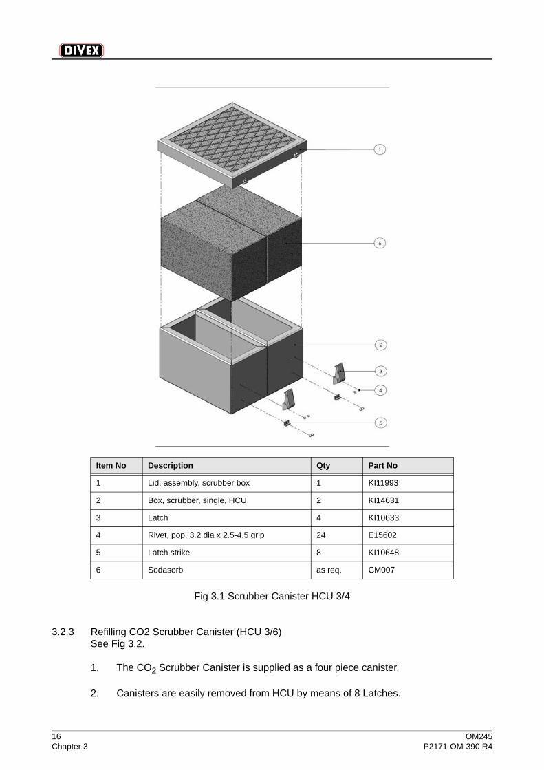
Fig 3.1 Scrubber Canister HCU 3/4
3.2.3 Refilling CO2 Scrubber Canister (HCU 3/6) See Fig 3.2.
1. The CO2 Scrubber Canister is supplied as a four piece canister.
2. Canisters are easily removed from HCU by means of 8 Latches.
Item No Description Qty Part No
1 Lid, assembly, scrubber box 1 KI11993
2 Box, scrubber, single, HCU 2 KI14631
3 Latch 4 KI10633
4 Rivet, pop, 3.2 dia x 2.5-4.5 grip 24 E15602
5 Latch strike 8 KI10648
6 Sodasorb as req. CM007

OM245 17P2171-OM-390 R4 Chapter 3
3. To empty CO2 Scrubber Canister (2), remove Lid, by unlatching 8 Latches (3) andpouring out used Sodasorb (6).
4. Fill CO2 Scrubber Canister with approximately 26kg (56 pounds) of Sodasorb (6).Pack Sodasorb down tightly for maximum performance.
5. Install Lid (1) and secure with 4 Latches (3). Then install CO2 Scrubber Canister onHCU and secure with 8 Latches.
Fig 3.2 Scrubber Canister HCU 3/6
Item No Description Qty Part No
1 Lid, assembly, scrubber box 1 KI11993
2 Box, scrubber, single, HCU 4 KI14631
3 Latch 8 KI10633
4 Latch strike 16 KI10648
5 Rivet, pop, 3.2 dia. x 2.5-4.5 grip 48 E15602
6 Sodasorb as req. CM007

18 OM245Chapter 3 P2171-OM-390 R4
(Intentionally Blank)

OM245 19P2171-OM-390 R4 Chapter 4
Chapter 4 - Maintenance & Repair
Contents
Page
4.1 Routine Maintenance Schedules, HCU 3/4 & HCU 3/6 .................................................. 204.1.1 Clean and Inspect HCU After 2,000 Hours ..................................................................... 20
4.2 Habitat Conditioning Unit Service - Electric Motor .......................................................... 21

20 OM245Chapter 4 P2171-OM-390 R4
4.1 Routine Maintenance Schedules, HCU 3/4 & HCU 3/6
4.1.1 Clean and Inspect HCU After 2,000 Hours
NoteHCU must be disassembled. See Fig 3.2.
1. Remove Sodasorb Canister and discard Sodasorb. Using clean, dry air source (30psi), blow debris out of Case, Reheat Coil Fins, Dehumidification Coil Fins, Plenum,CO2 Scrubber Canister and bottom of Case.
2. Using hot soap solution, clean inside and outside of entire HCU. Clean Reheat CoilFins, Dehumidification Coil Fins, and inside of CO2 Scrubber Canister. Rinse entire
unit with hot water and dry with air and clean, lint-free cloth.
CAUTION
Be sure CO2 scrubber canister and filter screen are completely dry before adding Sodasorb. Inspect HCU for signs of damage.

OM245 21P2171-OM-390 R4 Chapter 4
4.2 Habitat Conditioning Unit Service - Electric MotorThis motor is not user servicable, please contact Divex service department.

22 OM245Chapter 4 P2171-OM-390 R4
(Intentionally Blank)

OM245 23P2171-OM-390 R4 Chapter 4
Fig 4.1 HCU 3/4 (P217711S1 R3)

24 OM245Chapter 4 P2171-OM-390 R4
Fig 4.2 HCU 3/6 (P21713S1 R2)