Embed Size (px)
Citation preview
IOM MANUAL TITLE: Installation, Operation, and Maintenance Manual for the Offshore Treatment System
DOCUMENT MANAGEMENT NUMBER:
BUS. UNIT:
REGION:
Global FUNCTION:
Testing and Subsea
OWNER:
APPROVED BY:
JOB REVISION BY:
REV. DATE:
April 2014
REV. NO: A
SECTION: Water
Treatment
PAGE: 1 of 118
INSTALLATION, OPERATION, AND MAINTENANCE MANUAL FOR THE OFFSHORE TREATMENT SYSTEM
IOM MANUAL TITLE: Installation, Operation, and Maintenance Manual for the Offshore Treatment System
DOCUMENT MANAGEMENT NUMBER:
BUS. UNIT:
REGION:
Global FUNCTION:
Testing and Subsea
OWNER:
APPROVED BY:
JOB REVISION BY:
REV. DATE:
April 2014
REV. NO: A
SECTION: Water
Treatment
PAGE: 2 of 118
TABLE OF CONTENTS
SECTION 1 - CAUTIONS AND GENERAL SAFETY RULES ............................................... 5
GENERAL SAFETY ............................................................................................. 5
ELECTRICAL SAFETY ........................................................................................ 6
HYDRAULIC SAFETY .......................................................................................... 8
CHEMICAL SAFETY ............................................................................................ 9
EMERGENCY PROCEDURES ............................................................................ 9
SECTION 2 - INTRODUCTION AND THEORY OF OPERATIONS ......................................11
THEORY OF OPERATIONS OVERVIEW .......................................................... 11
TREATMENT TRAIN .......................................................................................... 12
EQUIPMENT OVERVIEW .................................................................................. 13
SECTION 3 - TREATMENT SYSTEM COMPONENTS ........................................................15
INFLUENT OIL-IN-WATER SENSOR (AE-INFOIW) .......................................... 15
OIL-IN-WATER DISPLAY ................................................................................... 15
PH PROBES....................................................................................................... 16
FLOW METERS (FE/FIT-INF AND FE/FIT-EFF) ................................................ 17
FLOW CONTROL VALVE (FCV-EC) ................................................................. 18
CONDUCTIVITY PROBE (AE-COND) ............................................................... 19
EC CONTROL PANEL ....................................................................................... 20
CELL ISOLATION VALVES ............................................................................... 21
EC CELLS .......................................................................................................... 22
HUMAN MACHINE INTERFACE (HMI) .............................................................. 22
CHEMICAL INJECTION PUMPS (P-CAUS AND P-POLY) ................................ 23
STATIC MIXER .................................................................................................. 23
FLOCCULATOR ................................................................................................. 24
IAF CONTROL PANEL ....................................................................................... 25
IAF COVER ........................................................................................................ 25
IAF EDUCTOR ................................................................................................... 26
IAF 26
POLE LIGHTS .................................................................................................... 33
POLISHING FILTERS ........................................................................................ 34
EFFLUENT OIL-IN-WATER SENSOR (AE-EFFOIW) ........................................ 35
SECTION 4 - SETUP AND INSTALLATION ........................................................................36
IOM MANUAL TITLE: Installation, Operation, and Maintenance Manual for the Offshore Treatment System
DOCUMENT MANAGEMENT NUMBER:
BUS. UNIT:
REGION:
Global FUNCTION:
Testing and Subsea
OWNER:
APPROVED BY:
JOB REVISION BY:
REV. DATE:
April 2014
REV. NO: A
SECTION: Water
Treatment
PAGE: 3 of 118
PHYSICAL INSTALLATION (ADJACENT) ......................................................... 36
PHYSICAL INSTALLATION (STACKED) ........................................................... 36
SECTION 5 - OPERATION...................................................................................................47
EC STARTUP PROCEDURE ............................................................................. 47
EC OPERATIONAL CONDITIONS ..................................................................... 51
IAF OPERATION ................................................................................................ 52
IAF CONTROL PANEL ....................................................................................... 52
IAF UNIT OPERATION TUNING ........................................................................ 53
HMI INTERFACE SCREENS ............................................................................. 56
SYSTEM STANDBY CONDITIONS ................................................................... 75
AUTOMATIC SHUTDOWN CONDITIONS ......................................................... 75
SYSTEM SHUTDOWN INSTRUCTIONS ........................................................... 76
POLE LIGHTS STATE INFORMATION ............................................................. 76
CHEMICAL INJECTION OPERATION ............................................................... 77
OIW LEVEL WILKS TEST .................................................................................. 80
POLISHING FILTER OPERATION ..................................................................... 81
SECTION 6 - TROUBLESHOOTING ....................................................................................83
SECTION 7 - MAINTENANCE .............................................................................................85
SHORT-TERM STANDBY PERIODS ................................................................. 85
LONG-TERM STORAGE.................................................................................... 85
SYSTEM DRAIN AND BLOWOUT PROCEDURE ............................................. 86
BAG FILTER REPLACEMENT ........................................................................... 86
EC MAINTENANCE ........................................................................................... 88
IAF MAINTENANCE ........................................................................................... 89
SECTION 8 - SPECIFICATIONS ..........................................................................................97
SECTION 9 - SENSOR INFORMATION ...............................................................................98
SENSOR OVERVIEW AND EVALUATION ........................................................ 98
SINGLE-POINT CALIBRATION ......................................................................... 98
ZERO POINT PROGRAMMING ....................................................................... 101
SENSOR ISSUE REMEDIATION PROCEDURES ........................................... 103
SENSOR CLEANING ....................................................................................... 103
ADJUSTING SENSOR OFFSET AND SLOPE ................................................. 105
SECTION 10 - PARTS LISTING ........................................................................................... 109
EC UNIT PARTS .............................................................................................. 109
GENERAL SYSTEM SPARES ......................................................................... 109
SECTION 11 - VARIABLE FREQUENCY DRIVE SETTINGS .............................................. 110

IOM MANUAL TITLE: Installation, Operation, and Maintenance Manual for the Offshore Treatment System
DOCUMENT MANAGEMENT NUMBER:
BUS. UNIT:
REGION:
Global FUNCTION:
Testing and Subsea
OWNER:
APPROVED BY:
JOB REVISION BY:
REV. DATE:
April 2014
REV. NO: A
SECTION: Water
Treatment
PAGE: 4 of 118
SECTION 12 - RELATED DOCUMENTATION..................................................................... 111
SECTION 13 - MAINTENANCE WORKSHEETS AND SCHEDULES .................................. 112
SECTION 14 - PIPING AND INSTRUMENTATION DIAGRAM ............................................ 118
IOM MANUAL TITLE: Installation, Operation, and Maintenance Manual for the Offshore Treatment System
DOCUMENT MANAGEMENT NUMBER:
BUS. UNIT:
REGION:
Global FUNCTION:
Testing and Subsea
OWNER:
APPROVED BY:
JOB REVISION BY:
REV. DATE:
April 2014
REV. NO: A
SECTION: Water
Treatment
PAGE: 5 of 118
SECTION 1 - CAUTIONS AND GENERAL SAFETY RULES
Observe the following rules and procedures to ensure a safe working environment.
GENERAL SAFETY
Display appropriate warning and safety signs near the treatment system.
Do not operate the EC unit without the control cabin properly purged and pressurized. Ensure the air supply and circulation equipment are functioning properly.
Note the locations of safety equipment such as a fire extinguisher and eye wash.
WARNING: Add any additional required fire extinguishers or safety equipment per local safety and installation requirements as required.
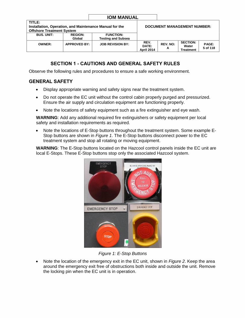
Note the locations of E-Stop buttons throughout the treatment system. Some example E-Stop buttons are shown in Figure 1. The E-Stop buttons disconnect power to the EC treatment system and stop all rotating or moving equipment.
WARNING: The E-Stop buttons located on the Hazcool control panels inside the EC unit are local E-Stops. These E-Stop buttons stop only the associated Hazcool system.
Figure 1: E-Stop Buttons
Note the location of the emergency exit in the EC unit, shown in Figure 2. Keep the area around the emergency exit free of obstructions both inside and outside the unit. Remove the locking pin when the EC unit is in operation.

IOM MANUAL TITLE: Installation, Operation, and Maintenance Manual for the Offshore Treatment System
DOCUMENT MANAGEMENT NUMBER:
BUS. UNIT:
REGION:
Global FUNCTION:
Testing and Subsea
OWNER:
APPROVED BY:
JOB REVISION BY:
REV. DATE:
April 2014
REV. NO: A
SECTION: Water
Treatment
PAGE: 6 of 118
Figure 2: Emergency Exit
Note the location of the manual alarm call point (MAC) in the EC unit transfer area. Periodically test the MAC by inserting the attached key into the bottom of the case. Turn the key to move the lever inside the glass cover. This allows the operator to test the MAC and alarm without breaking the glass cover.
Figure 3: Manual Alarm Call Point
ELECTRICAL SAFETY
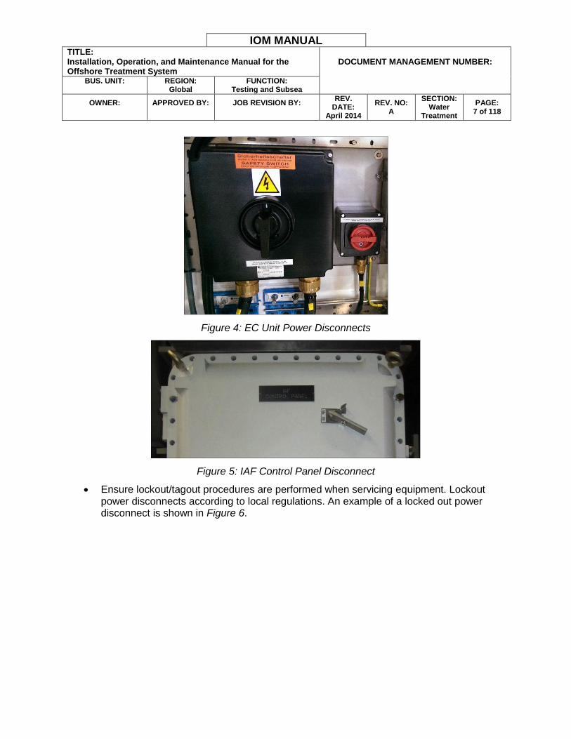
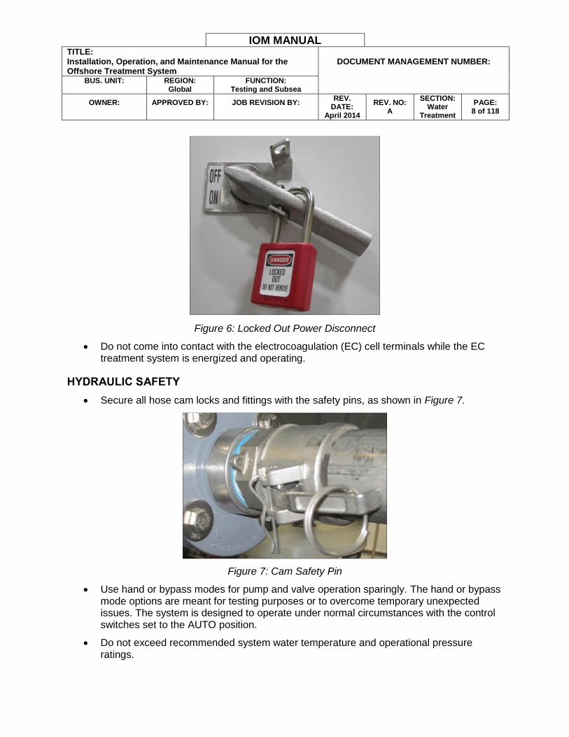
Use the power disconnect switches located in the EC unit recess and on the IAF unit control panel to disable system power when necessary, such as before connecting or disconnecting any equipment. The EC power disconnects are located in the EC unit external recess and are shown in Figure 4. The IAF disconnect is located on the top of the control panel, as shown in Figure 5.
IOM MANUAL TITLE: Installation, Operation, and Maintenance Manual for the Offshore Treatment System
DOCUMENT MANAGEMENT NUMBER:
BUS. UNIT:
REGION:
Global FUNCTION:
Testing and Subsea
OWNER:
APPROVED BY:
JOB REVISION BY:
REV. DATE:
April 2014
REV. NO: A
SECTION: Water
Treatment
PAGE: 7 of 118
Figure 4: EC Unit Power Disconnects
Figure 5: IAF Control Panel Disconnect
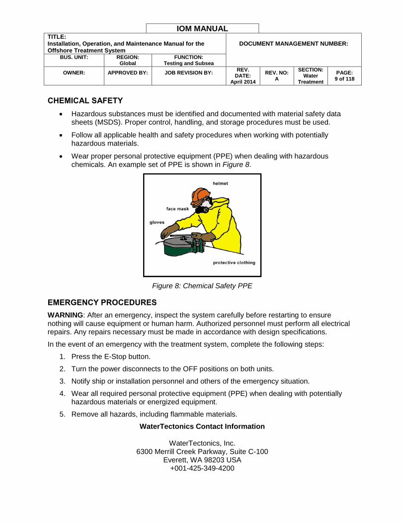
Ensure lockout/tagout procedures are performed when servicing equipment. Lockout power disconnects according to local regulations. An example of a locked out power disconnect is shown in Figure 6.
IOM MANUAL TITLE: Installation, Operation, and Maintenance Manual for the Offshore Treatment System
DOCUMENT MANAGEMENT NUMBER:
BUS. UNIT:
REGION:
Global FUNCTION:
Testing and Subsea
OWNER:
APPROVED BY:
JOB REVISION BY:
REV. DATE:
April 2014
REV. NO: A
SECTION: Water
Treatment
PAGE: 8 of 118
Figure 6: Locked Out Power Disconnect
Do not come into contact with the electrocoagulation (EC) cell terminals while the EC treatment system is energized and operating.
HYDRAULIC SAFETY
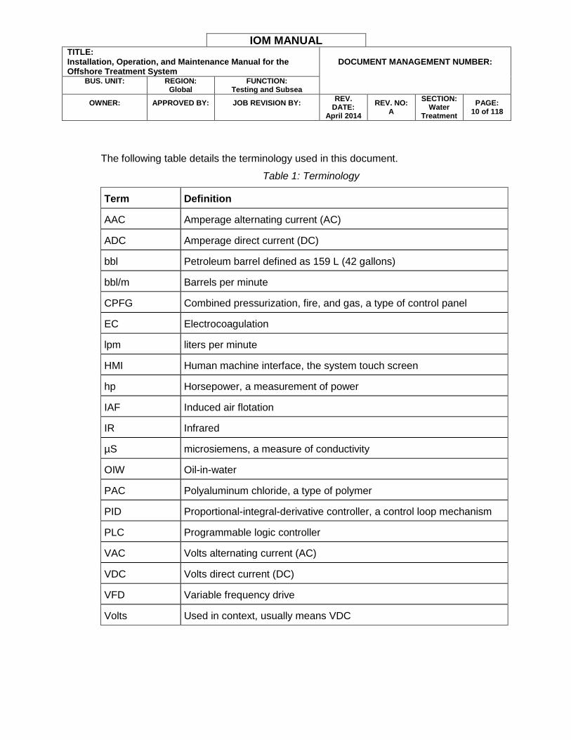
Secure all hose cam locks and fittings with the safety pins, as shown in Figure 7.
Figure 7: Cam Safety Pin
Use hand or bypass modes for pump and valve operation sparingly. The hand or bypass mode options are meant for testing purposes or to overcome temporary unexpected issues. The system is designed to operate under normal circumstances with the control switches set to the AUTO position.
Do not exceed recommended system water temperature and operational pressure ratings.
IOM MANUAL TITLE: Installation, Operation, and Maintenance Manual for the Offshore Treatment System
DOCUMENT MANAGEMENT NUMBER:
BUS. UNIT:
REGION:
Global FUNCTION:
Testing and Subsea
OWNER:
APPROVED BY:
JOB REVISION BY:
REV. DATE:
April 2014
REV. NO: A
SECTION: Water
Treatment
PAGE: 9 of 118
CHEMICAL SAFETY
Hazardous substances must be identified and documented with material safety data sheets (MSDS). Proper control, handling, and storage procedures must be used.
Follow all applicable health and safety procedures when working with potentially hazardous materials.
Wear proper personal protective equipment (PPE) when dealing with hazardous chemicals. An example set of PPE is shown in Figure 8.
Figure 8: Chemical Safety PPE
EMERGENCY PROCEDURES
WARNING: After an emergency, inspect the system carefully before restarting to ensure nothing will cause equipment or human harm. Authorized personnel must perform all electrical repairs. Any repairs necessary must be made in accordance with design specifications.
In the event of an emergency with the treatment system, complete the following steps:
1. Press the E-Stop button.
2. Turn the power disconnects to the OFF positions on both units.
3. Notify ship or installation personnel and others of the emergency situation.
4. Wear all required personal protective equipment (PPE) when dealing with potentially hazardous materials or energized equipment.
5. Remove all hazards, including flammable materials.
WaterTectonics Contact Information
WaterTectonics, Inc. 6300 Merrill Creek Parkway, Suite C-100
Everett, WA 98203 USA +001-425-349-4200
IOM MANUAL TITLE: Installation, Operation, and Maintenance Manual for the Offshore Treatment System
DOCUMENT MANAGEMENT NUMBER:
BUS. UNIT:
REGION:
Global FUNCTION:
Testing and Subsea
OWNER:
APPROVED BY:
JOB REVISION BY:
REV. DATE:
April 2014
REV. NO: A
SECTION: Water
Treatment
PAGE: 10 of 118
The following table details the terminology used in this document.
Table 1: Terminology
Term Definition
AAC Amperage alternating current (AC)
ADC Amperage direct current (DC)
bbl Petroleum barrel defined as 159 L (42 gallons)
bbl/m Barrels per minute
CPFG Combined pressurization, fire, and gas, a type of control panel
EC Electrocoagulation
lpm liters per minute
HMI Human machine interface, the system touch screen
hp Horsepower, a measurement of power
IAF Induced air flotation
IR Infrared
µS microsiemens, a measure of conductivity
OIW Oil-in-water
PAC Polyaluminum chloride, a type of polymer
PID Proportional-integral-derivative controller, a control loop mechanism
PLC Programmable logic controller
VAC Volts alternating current (AC)
VDC Volts direct current (DC)
VFD Variable frequency drive
Volts Used in context, usually means VDC
IOM MANUAL TITLE: Installation, Operation, and Maintenance Manual for the Offshore Treatment System
DOCUMENT MANAGEMENT NUMBER:
BUS. UNIT:
REGION:
Global FUNCTION:
Testing and Subsea
OWNER:
APPROVED BY:
JOB REVISION BY:
REV. DATE:
April 2014
REV. NO: A
SECTION: Water
Treatment
PAGE: 11 of 118
SECTION 2 - INTRODUCTION AND THEORY OF OPERATIONS
This manual contains instructions for the installation, operation, and maintenance of the treatment water treatment system. The intended audience includes operators and trained system technicians.
THEORY OF OPERATIONS OVERVIEW
The electrocoagulation (EC) cells provide the electrochemical reaction that destabilizes the oil and other contaminants emulsified and suspended in solution. This reaction causes the destabilization and aggregation of smaller particles into larger particles. Water contaminants such as ions and colloids are primarily held in solution by electrical charges. Colloidal systems are destabilized by the addition of ions with a charge opposite to the colloidal charge. The oppositely charged particles attract each other and promote the formation of removable flocculent masses. In the EC process contaminated water flows between closely spaced metal plates. DC voltage is applied across the plates to create a high electrical current. The polarity is reversed periodically to avoid buildup on the plates and in the cell.
Chemical injection in the treatment process serves two primary functions:
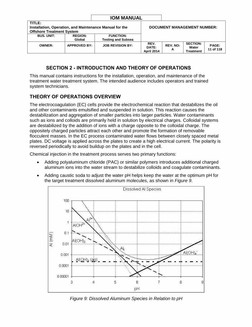
Adding polyaluminum chloride (PAC) or similar polymers introduces additional charged aluminum ions into the water stream to destabilize colloids and coagulate contaminants.
Adding caustic soda to adjust the water pH helps keep the water at the optimum pH for the target treatment dissolved aluminum molecules, as shown in Figure 9.
Figure 9: Dissolved Aluminum Species in Relation to pH
IOM MANUAL TITLE: Installation, Operation, and Maintenance Manual for the Offshore Treatment System
DOCUMENT MANAGEMENT NUMBER:
BUS. UNIT:
REGION:
Global FUNCTION:
Testing and Subsea
OWNER:
APPROVED BY:
JOB REVISION BY:
REV. DATE:
April 2014
REV. NO: A
SECTION: Water
Treatment
PAGE: 12 of 118
After EC treatment, the coagulating particles pass through the static mixer to the flocculator where larger flocculent masses are formed. This water stream then enters the IAF stage. The IAF unit reduces the surface charges on the oil droplets and promotes coagulation and agglomeration. Light or small flocculent masses bond to and are lifted by microbubbles generated by the IAF unit. A skimmer chain and flight system scrapes this floating sludge layer from the top of the water to a sludge hopper. Flocculent masses with a high enough mass sink to the bottom of the IAF and are removed by the sludge pump. Any remaining coagulated material or contaminants are removed by bag or polishing filters prior to discharge.
TREATMENT TRAIN
The treatment train is designed to treat produced flowback water utilizing electrocoagulation and induced air flotation as the primary treatment processes. Additional functions, such as pH adjustment and polymer injection improve the ability of the electrocoagulation and IAF stages to remove precipitates. The system monitors and manages effluent oil-in-water (OIW) content and pH in real time. Certain water quality parameter tolerances are user-configurable.
The process of the electrocoagulation treatment train is outlined below:
Electrocoagulation: By applying an electrical charge through metal plates to a solution of contaminated water, electrocoagulation destabilizes the charges on the various contaminant particles and generates a coagulation reaction.
Coagulant Supplement: When necessary, the system has the ability to add PAC or similar polymers to the water stream after the EC stage. The polymer solution adds additional, highly-charged coagulant before the IAF stage to increase system performance.
pH Adjustment: The system monitors the influent water pH and doses the water with caustic soda to raise the pH before the IAF stage. Raising the water pH to a more neutral value helps the coagulation process by enabling the aluminum molecules to remain dissolved in solution.
Separation/Settling and Coagulation: In this phase of the treatment train, the electrically-charged particles coagulate and settle within a system of pipes and an IAF unit. The rate at which these contaminants precipitate out of solution and join together to form coagulated precipitates varies with water characteristics.
Mechanical and Polishing Filtration: Filtration removes the remaining contaminants that either formed after the clarification stage or were too small to settle out of the water column. A bag filter removes particulates down to a small micron level. Polishing filters can remove remaining traces of oil to ensure discharge compliance.
Performance: With proper operation and maintenance, the treatment system can break oil emulsion and remove oil contaminants, remove the majority of total suspended solids (TSS), and remove dissolved metals.
IOM MANUAL TITLE: Installation, Operation, and Maintenance Manual for the Offshore Treatment System
DOCUMENT MANAGEMENT NUMBER:
BUS. UNIT:
REGION:
Global FUNCTION:
Testing and Subsea
OWNER:
APPROVED BY:
JOB REVISION BY:
REV. DATE:
April 2014
REV. NO: A
SECTION: Water
Treatment
PAGE: 13 of 118
Water Quality Monitoring: If the influent OIW parameters are too high for the
system to effectively treat, the system has the ability to automatically reject and recirculate this water. This protects the system from potential damage. If the effluent OIW water quality parameters are exceeded, the system has the ability to recirculate effluent water through the treatment train until the water quality is within configured discharge parameters.
EQUIPMENT OVERVIEW
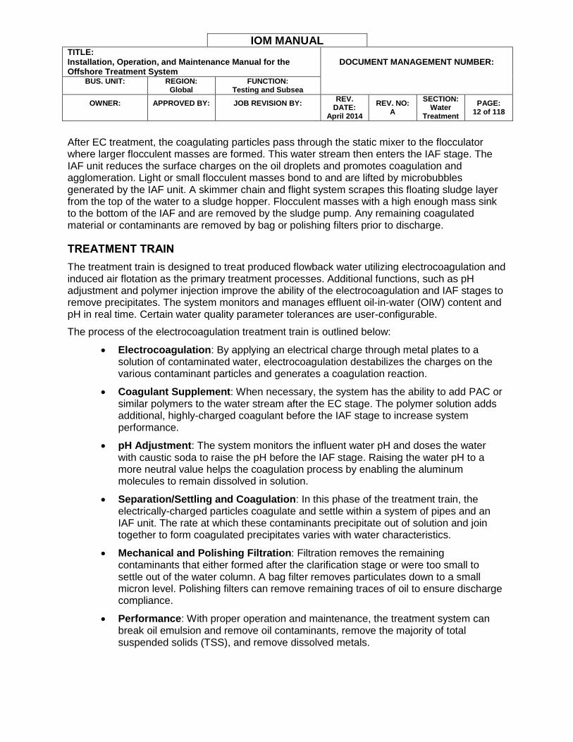
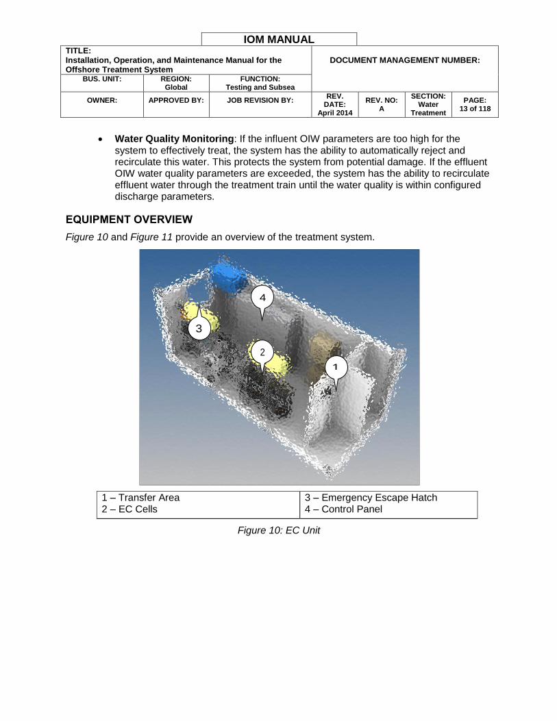
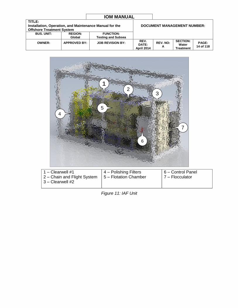
Figure 10 and Figure 11 provide an overview of the treatment system.
1 – Transfer Area 2 – EC Cells
3 – Emergency Escape Hatch 4 – Control Panel
Figure 10: EC Unit
1
2
4
3
IOM MANUAL TITLE: Installation, Operation, and Maintenance Manual for the Offshore Treatment System
DOCUMENT MANAGEMENT NUMBER:
BUS. UNIT:
REGION:
Global FUNCTION:
Testing and Subsea
OWNER:
APPROVED BY:
JOB REVISION BY:
REV. DATE:
April 2014
REV. NO: A
SECTION: Water
Treatment
PAGE: 14 of 118
1 – Clearwell #1 2 – Chain and Flight System 3 – Clearwell #2
4 – Polishing Filters 5 – Flotation Chamber
6 – Control Panel 7 – Flocculator
Figure 11: IAF Unit
3
4
6
7
2
5
1
IOM MANUAL TITLE: Installation, Operation, and Maintenance Manual for the Offshore Treatment System
DOCUMENT MANAGEMENT NUMBER:
BUS. UNIT:
REGION:
Global FUNCTION:
Testing and Subsea
OWNER:
APPROVED BY:
JOB REVISION BY:
REV. DATE:
April 2014
REV. NO: A
SECTION: Water
Treatment
PAGE: 15 of 118
SECTION 3 - TREATMENT SYSTEM COMPONENTS
The following sections describe the treatment system components and their various functions.
INFLUENT OIL-IN-WATER SENSOR (AE-INFOIW)
A REDACTED MODEL monitors the influent OIW characteristics. The influent OIW sensor is an infrared (IR) absorption sensor that detects quantities of oil and other contaminants by measuring the attenuation of light passing through the water. The treatment system uses the sensor as a reference instrument to provide repeatable contaminant response. The primary function of the influent OIW sensor is protecting the system from processing water with OIW quantities too high for the equipment to process. To protect the system from potential damage, the PLC monitors the sensor signal and rejects any influent water with a reference concentration higher than the programmed setpoint. The factory rejection setpoint is REDACTED ppm.
Figure 12: Influent OIW Sensor
OIL-IN-WATER DISPLAY
A REDACTED MODEL converter mounted in the EC control cabinet displays both the influent and effluent OIW sensor information. The converter transmits OIW information to the PLC to control discharge or recirculation water flow.
For additional information about the converter and all related settings and functions, refer to the manufacturer’s documentation.
IOM MANUAL TITLE: Installation, Operation, and Maintenance Manual for the Offshore Treatment System
DOCUMENT MANAGEMENT NUMBER:
BUS. UNIT:
REGION:
Global FUNCTION:
Testing and Subsea
OWNER:
APPROVED BY:
JOB REVISION BY:
REV. DATE:
April 2014
REV. NO: A
SECTION: Water
Treatment
PAGE: 16 of 118
Figure 13: OIW Display
PH PROBES
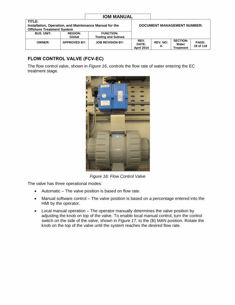
Two pH probes, one shown in Figure 14, monitor water pH in the following locations:
The first pH probe (AT-INFPH) measures the influent water pH before the EC stage.
The second pH probe (AT-EFFPH) measures the effluent water pH after the IAF stage, or polishing filter stage when polishing is enabled.
Figure 14: pH Probe
The pH probe outputs are monitored by the PLC. The PLC has an ON and OFF band that automatically enables or disables the caustic injection pump based on the pH readings.
WARNING: Do not store the pH probes at temperatures below 4.4 °C (40 °F) or without their protective caps.

IOM MANUAL TITLE: Installation, Operation, and Maintenance Manual for the Offshore Treatment System
DOCUMENT MANAGEMENT NUMBER:
BUS. UNIT:
REGION:
Global FUNCTION:
Testing and Subsea
OWNER:
APPROVED BY:
JOB REVISION BY:
REV. DATE:
April 2014
REV. NO: A
SECTION: Water
Treatment
PAGE: 17 of 118
FLOW METERS (FE/FIT-INF AND FE/FIT-EFF)
Two electromagnetic flow meters monitor both the influent and effluent flow rate and communicate the information to the PLC. They also feature digital displays showing real-time flow rate information. The operator can use flow meter readings to gauge system performance, alert them to a system problem, and record discharge totals for regulatory purposes.
For additional information about the flow meters, settings, display options, and calibration procedures, refer to the manufacturer’s documentation.
Figure 15: Flow Meter
IOM MANUAL TITLE: Installation, Operation, and Maintenance Manual for the Offshore Treatment System
DOCUMENT MANAGEMENT NUMBER:
BUS. UNIT:
REGION:
Global FUNCTION:
Testing and Subsea
OWNER:
APPROVED BY:
JOB REVISION BY:
REV. DATE:
April 2014
REV. NO: A
SECTION: Water
Treatment
PAGE: 18 of 118
FLOW CONTROL VALVE (FCV-EC)
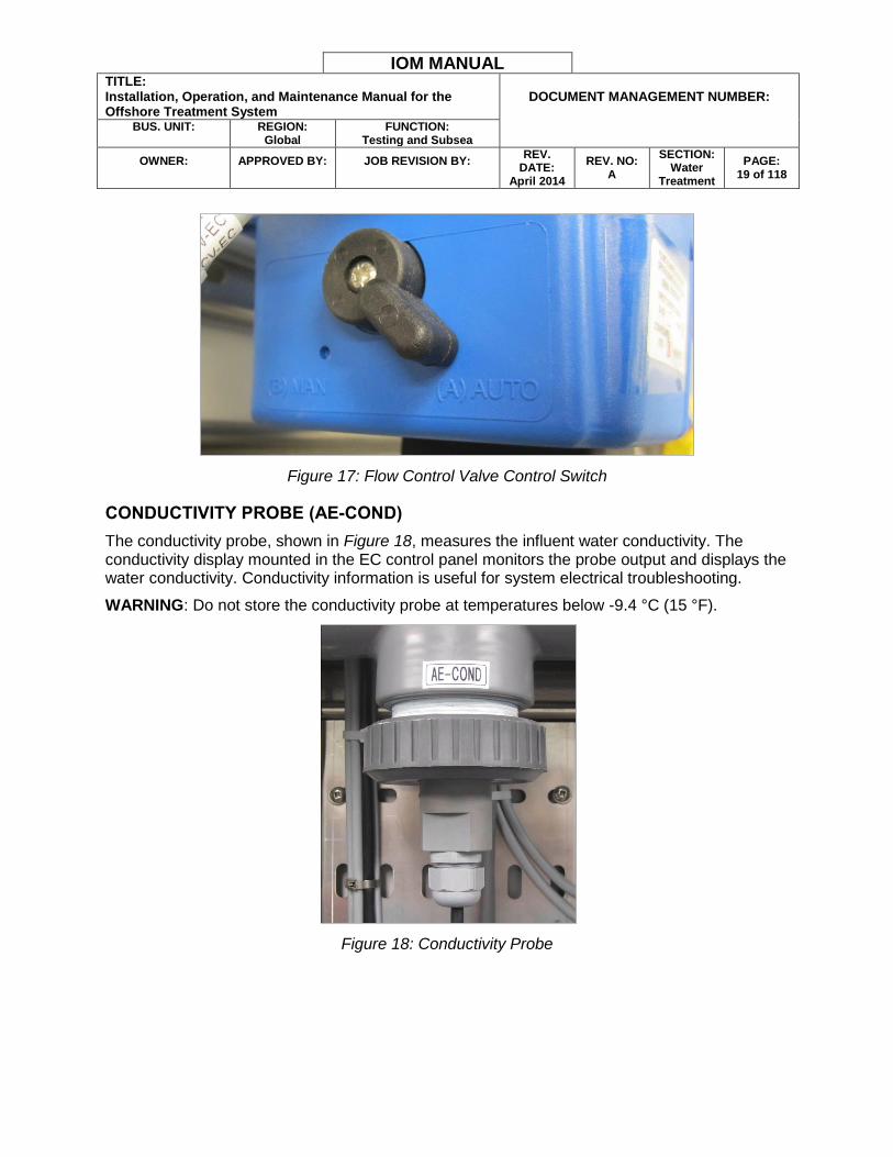
The flow control valve, shown in Figure 16, controls the flow rate of water entering the EC treatment stage.
Figure 16: Flow Control Valve
The valve has three operational modes:
Automatic – The valve position is based on flow rate.
Manual software control – The valve position is based on a percentage entered into the HMI by the operator.
Local manual operation – The operator manually determines the valve position by adjusting the knob on top of the valve. To enable local manual control, turn the control switch on the side of the valve, shown in Figure 17, to the (B) MAN position. Rotate the knob on the top of the valve until the system reaches the desired flow rate.
IOM MANUAL TITLE: Installation, Operation, and Maintenance Manual for the Offshore Treatment System
DOCUMENT MANAGEMENT NUMBER:
BUS. UNIT:
REGION:
Global FUNCTION:
Testing and Subsea
OWNER:
APPROVED BY:
JOB REVISION BY:
REV. DATE:
April 2014
REV. NO: A
SECTION: Water
Treatment
PAGE: 19 of 118
Figure 17: Flow Control Valve Control Switch
CONDUCTIVITY PROBE (AE-COND)
The conductivity probe, shown in Figure 18, measures the influent water conductivity. The conductivity display mounted in the EC control panel monitors the probe output and displays the water conductivity. Conductivity information is useful for system electrical troubleshooting.
WARNING: Do not store the conductivity probe at temperatures below -9.4 °C (15 °F).
Figure 18: Conductivity Probe
IOM MANUAL TITLE: Installation, Operation, and Maintenance Manual for the Offshore Treatment System
DOCUMENT MANAGEMENT NUMBER:
BUS. UNIT:
REGION:
Global FUNCTION:
Testing and Subsea
OWNER:
APPROVED BY:
JOB REVISION BY:
REV. DATE:
April 2014
REV. NO: A
SECTION: Water
Treatment
PAGE: 22 of 118
Figure 21: EC Isolation Valve
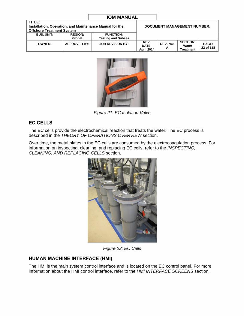
EC CELLS
The EC cells provide the electrochemical reaction that treats the water. The EC process is described in the THEORY OF OPERATIONS OVERVIEW section.
Over time, the metal plates in the EC cells are consumed by the electrocoagulation process. For information on inspecting, cleaning, and replacing EC cells, refer to the INSPECTING, CLEANING, AND REPLACING CELLS section.
Figure 22: EC Cells
HUMAN MACHINE INTERFACE (HMI)
The HMI is the main system control interface and is located on the EC control panel. For more information about the HMI control interface, refer to the HMI INTERFACE SCREENS section.

IOM MANUAL TITLE: Installation, Operation, and Maintenance Manual for the Offshore Treatment System
DOCUMENT MANAGEMENT NUMBER:
BUS. UNIT:
REGION:
Global FUNCTION:
Testing and Subsea
OWNER:
APPROVED BY:
JOB REVISION BY:
REV. DATE:
April 2014
REV. NO: A
SECTION: Water
Treatment
PAGE: 23 of 118
CHEMICAL INJECTION PUMPS (P-CAUS AND P-POLY)
Two chemical injection pumps inject caustic soda or polymer additive into the water stream when necessary. Each chemical solution is injected by a separate pump. Switch controls for both pumps are located on the IAF unit control panel. Caustic soda injection for pH adjustment purposes is controlled by the PLC when the CAUSTIC PUMP switch is in the AUTO position. The PLC will call the pumps to perform chemical injection when flow is detected to prevent undiluted chemical from being injected into the pipe. Refer to the CHEMICAL INJECTION OPERATION section for more information about chemical injection functions.
Note: The flow rate for both chemical injection pumps must be manually adjusted on the pump.
Figure 23: Chemical Injection Pump
STATIC MIXER
The static mixer continuously mixes the influent water stream before the water enters the flocculator. Radial mixing causes the charged ions introduced by the EC treatment process to collide more frequently with water contaminants and form larger flocculent precipitates. When necessary, a polymer is added to the water stream immediately before the static mixer. The static mixer also enhances the effectiveness of the polymer additive, when the additive is present, by causing more frequent particle collisions.
IOM MANUAL TITLE: Installation, Operation, and Maintenance Manual for the Offshore Treatment System
DOCUMENT MANAGEMENT NUMBER:
BUS. UNIT:
REGION:
Global FUNCTION:
Testing and Subsea
OWNER:
APPROVED BY:
JOB REVISION BY:
REV. DATE:
April 2014
REV. NO: A
SECTION: Water
Treatment
PAGE: 24 of 118
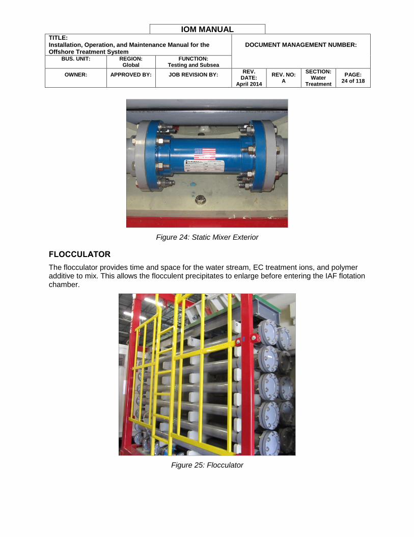
Figure 24: Static Mixer Exterior
FLOCCULATOR
The flocculator provides time and space for the water stream, EC treatment ions, and polymer additive to mix. This allows the flocculent precipitates to enlarge before entering the IAF flotation chamber.
Figure 25: Flocculator
IOM MANUAL TITLE: Installation, Operation, and Maintenance Manual for the Offshore Treatment System
DOCUMENT MANAGEMENT NUMBER:
BUS. UNIT:
REGION:
Global FUNCTION:
Testing and Subsea
OWNER:
APPROVED BY:
JOB REVISION BY:
REV. DATE:
April 2014
REV. NO: A
SECTION: Water
Treatment
PAGE: 25 of 118
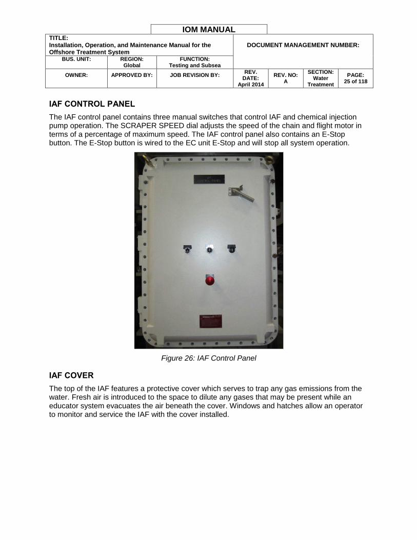
IAF CONTROL PANEL
The IAF control panel contains three manual switches that control IAF and chemical injection pump operation. The SCRAPER SPEED dial adjusts the speed of the chain and flight motor in terms of a percentage of maximum speed. The IAF control panel also contains an E-Stop button. The E-Stop button is wired to the EC unit E-Stop and will stop all system operation.
Figure 26: IAF Control Panel
IAF COVER
The top of the IAF features a protective cover which serves to trap any gas emissions from the water. Fresh air is introduced to the space to dilute any gases that may be present while an educator system evacuates the air beneath the cover. Windows and hatches allow an operator to monitor and service the IAF with the cover installed.
IOM MANUAL TITLE: Installation, Operation, and Maintenance Manual for the Offshore Treatment System
DOCUMENT MANAGEMENT NUMBER:
BUS. UNIT:
REGION:
Global FUNCTION:
Testing and Subsea
OWNER:
APPROVED BY:
JOB REVISION BY:
REV. DATE:
April 2014
REV. NO: A
SECTION: Water
Treatment
PAGE: 26 of 118
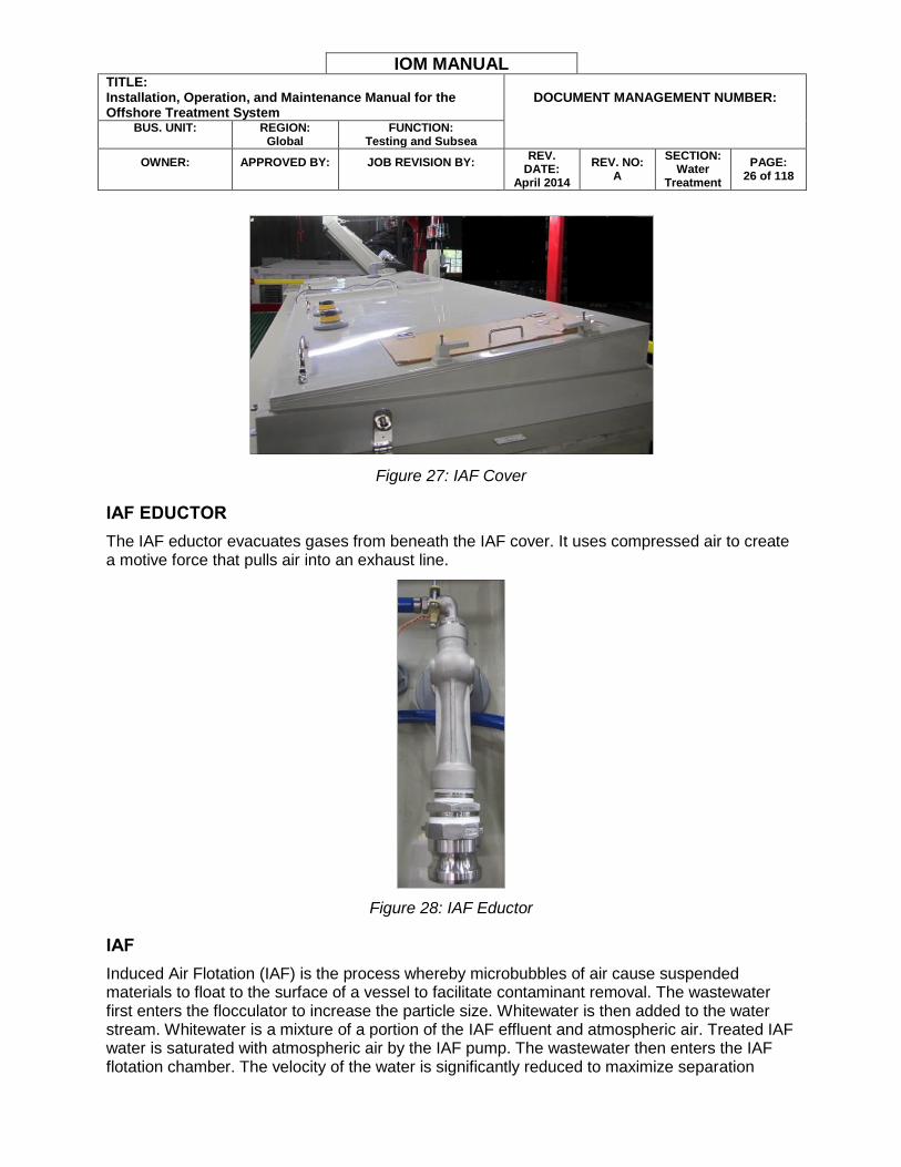
Figure 27: IAF Cover
IAF EDUCTOR
The IAF eductor evacuates gases from beneath the IAF cover. It uses compressed air to create a motive force that pulls air into an exhaust line.
Figure 28: IAF Eductor
IAF
Induced Air Flotation (IAF) is the process whereby microbubbles of air cause suspended materials to float to the surface of a vessel to facilitate contaminant removal. The wastewater first enters the flocculator to increase the particle size. Whitewater is then added to the water stream. Whitewater is a mixture of a portion of the IAF effluent and atmospheric air. Treated IAF water is saturated with atmospheric air by the IAF pump. The wastewater then enters the IAF flotation chamber. The velocity of the water is significantly reduced to maximize separation
IOM MANUAL TITLE: Installation, Operation, and Maintenance Manual for the Offshore Treatment System
DOCUMENT MANAGEMENT NUMBER:
BUS. UNIT:
REGION:
Global FUNCTION:
Testing and Subsea
OWNER:
APPROVED BY:
JOB REVISION BY:
REV. DATE:
April 2014
REV. NO: A
SECTION: Water
Treatment
PAGE: 27 of 118
potential. Inside the flotation chamber the microbubbles, having attached to the contaminant particles and affected the particle density, cause the suspended contaminants to float to the surface. A chain and flight skimmer system removes the floating sludge layer from the flotation chamber surface into a sludge hopper. The treated water is continuously removed at several points inside the flotation chamber and passes over pipe weirs into two clearwells. The treated wastewater leaves the IAF unit from clearwell #2. The IAF is designed to separate and remove particulates above REDACTED microns in size.
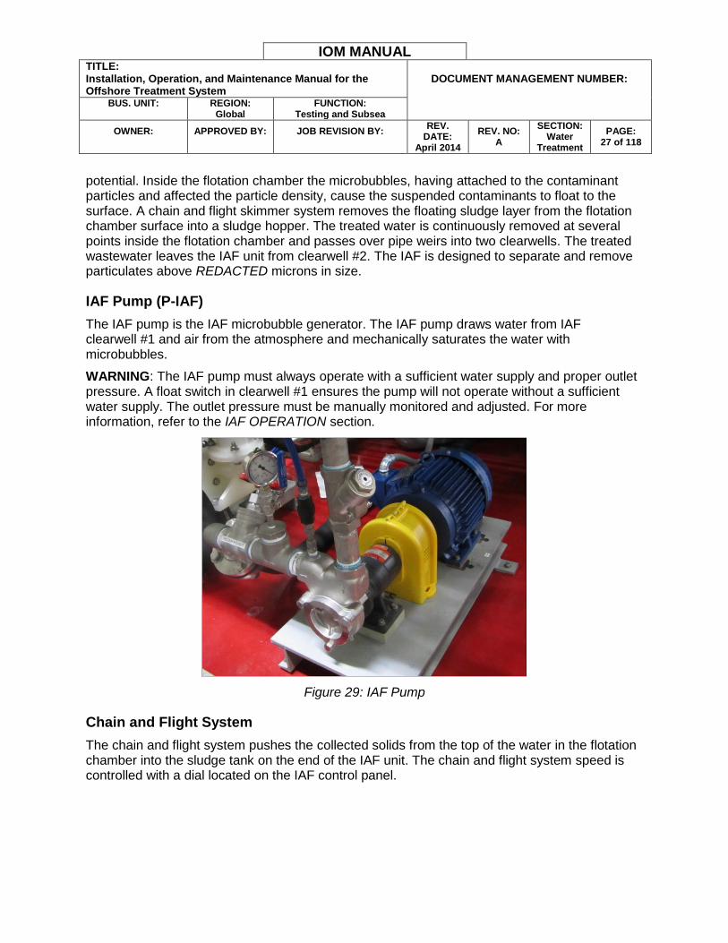
IAF Pump (P-IAF)
The IAF pump is the IAF microbubble generator. The IAF pump draws water from IAF clearwell #1 and air from the atmosphere and mechanically saturates the water with microbubbles.
WARNING: The IAF pump must always operate with a sufficient water supply and proper outlet pressure. A float switch in clearwell #1 ensures the pump will not operate without a sufficient water supply. The outlet pressure must be manually monitored and adjusted. For more information, refer to the IAF OPERATION section.
Figure 29: IAF Pump
Chain and Flight System
The chain and flight system pushes the collected solids from the top of the water in the flotation chamber into the sludge tank on the end of the IAF unit. The chain and flight system speed is controlled with a dial located on the IAF control panel.
IOM MANUAL TITLE: Installation, Operation, and Maintenance Manual for the Offshore Treatment System
DOCUMENT MANAGEMENT NUMBER:
BUS. UNIT:
REGION:
Global FUNCTION:
Testing and Subsea
OWNER:
APPROVED BY:
JOB REVISION BY:
REV. DATE:
April 2014
REV. NO: A
SECTION: Water
Treatment
PAGE: 30 of 118
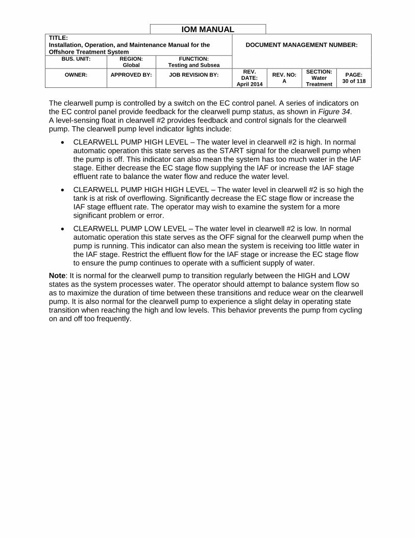
The clearwell pump is controlled by a switch on the EC control panel. A series of indicators on the EC control panel provide feedback for the clearwell pump status, as shown in Figure 34. A level-sensing float in clearwell #2 provides feedback and control signals for the clearwell pump. The clearwell pump level indicator lights include:
CLEARWELL PUMP HIGH LEVEL – The water level in clearwell #2 is high. In normal automatic operation this state serves as the START signal for the clearwell pump when the pump is off. This indicator can also mean the system has too much water in the IAF stage. Either decrease the EC stage flow supplying the IAF or increase the IAF stage effluent rate to balance the water flow and reduce the water level.
CLEARWELL PUMP HIGH HIGH LEVEL – The water level in clearwell #2 is so high the tank is at risk of overflowing. Significantly decrease the EC stage flow or increase the IAF stage effluent rate. The operator may wish to examine the system for a more significant problem or error.
CLEARWELL PUMP LOW LEVEL – The water level in clearwell #2 is low. In normal automatic operation this state serves as the OFF signal for the clearwell pump when the pump is running. This indicator can also mean the system is receiving too little water in the IAF stage. Restrict the effluent flow for the IAF stage or increase the EC stage flow to ensure the pump continues to operate with a sufficient supply of water.
Note: It is normal for the clearwell pump to transition regularly between the HIGH and LOW states as the system processes water. The operator should attempt to balance system flow so as to maximize the duration of time between these transitions and reduce wear on the clearwell pump. It is also normal for the clearwell pump to experience a slight delay in operating state transition when reaching the high and low levels. This behavior prevents the pump from cycling on and off too frequently.
IOM MANUAL TITLE: Installation, Operation, and Maintenance Manual for the Offshore Treatment System
DOCUMENT MANAGEMENT NUMBER:
BUS. UNIT:
REGION:
Global FUNCTION:
Testing and Subsea
OWNER:
APPROVED BY:
JOB REVISION BY:
REV. DATE:
April 2014
REV. NO: A
SECTION: Water
Treatment
PAGE: 31 of 118
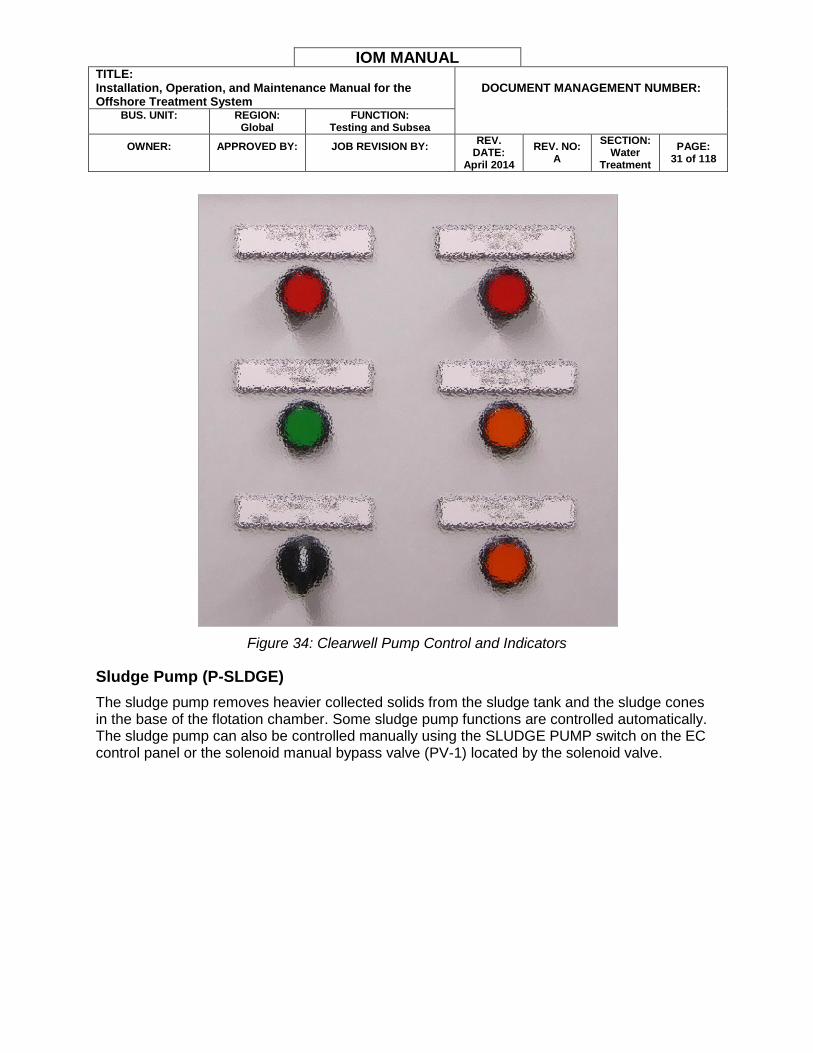
Figure 34: Clearwell Pump Control and Indicators
Sludge Pump (P-SLDGE)
The sludge pump removes heavier collected solids from the sludge tank and the sludge cones in the base of the flotation chamber. Some sludge pump functions are controlled automatically. The sludge pump can also be controlled manually using the SLUDGE PUMP switch on the EC control panel or the solenoid manual bypass valve (PV-1) located by the solenoid valve.

IOM MANUAL TITLE: Installation, Operation, and Maintenance Manual for the Offshore Treatment System
DOCUMENT MANAGEMENT NUMBER:
BUS. UNIT:
REGION:
Global FUNCTION:
Testing and Subsea
OWNER:
APPROVED BY:
JOB REVISION BY:
REV. DATE:
April 2014
REV. NO: A
SECTION: Water
Treatment
PAGE: 32 of 118
Figure 35: Sludge Pump
Note: To manually drain from the sludge cone bottoms, the corresponding cone bottom valve switch must be set to HAND to open the valve before switching the SLUDGE PUMP switch to HAND.
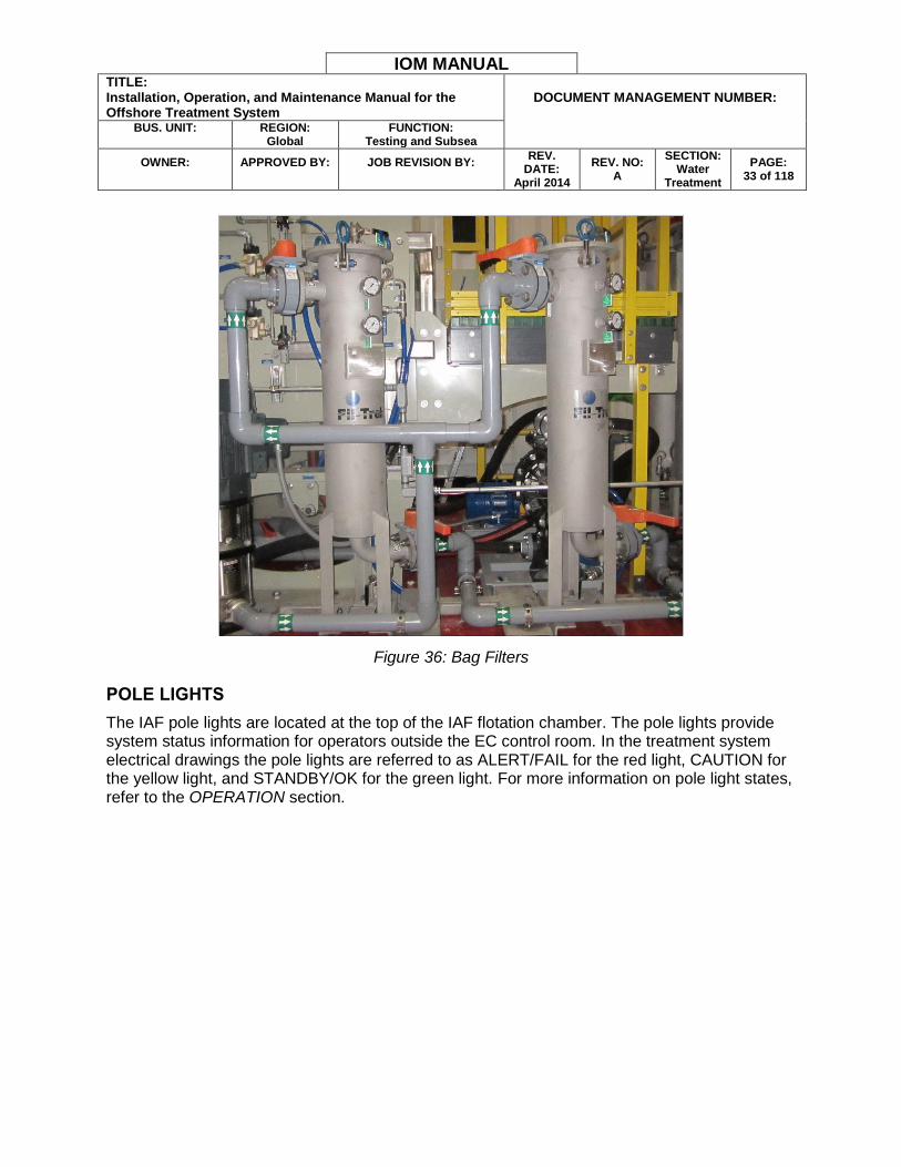
Bag Filters
Two bag filters, shown in Figure 36, remove remaining particulates down to a small micron level after the IAF treatment stage. The treatment system can operate with only one bag filter operational and the other isolated for inspection or maintenance purposes. An empty bag filter chamber can also serve as a bypass when particulate filtration is not required and the polishing filters are not in operation. The recommended configuration is to operate with both bag filters in the hydraulic path.
WARNING: The bag filters protect the much more expensive polishing filters from becoming clogged with particulates. The manufacturer recommends using bag filters that remove particulates of REDACTED micron (nominal) or smaller. Do not use a bag filter with a rating higher than REDACTED micron (nominal) when operating the polishing filters.
Ensure the bag filters are installed and in good condition before diverting water through the polishing filter. Refer to the BAG FILTER REPLACEMENT section for information on monitoring and replacing the bag filters.
IOM MANUAL TITLE: Installation, Operation, and Maintenance Manual for the Offshore Treatment System
DOCUMENT MANAGEMENT NUMBER:
BUS. UNIT:
REGION:
Global FUNCTION:
Testing and Subsea
OWNER:
APPROVED BY:
JOB REVISION BY:
REV. DATE:
April 2014
REV. NO: A
SECTION: Water
Treatment
PAGE: 33 of 118
Figure 36: Bag Filters
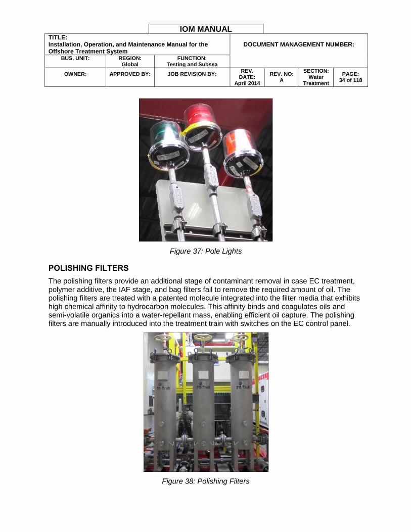
POLE LIGHTS
The IAF pole lights are located at the top of the IAF flotation chamber. The pole lights provide system status information for operators outside the EC control room. In the treatment system electrical drawings the pole lights are referred to as ALERT/FAIL for the red light, CAUTION for the yellow light, and STANDBY/OK for the green light. For more information on pole light states, refer to the OPERATION section.
IOM MANUAL TITLE: Installation, Operation, and Maintenance Manual for the Offshore Treatment System
DOCUMENT MANAGEMENT NUMBER:
BUS. UNIT:
REGION:
Global FUNCTION:
Testing and Subsea
OWNER:
APPROVED BY:
JOB REVISION BY:
REV. DATE:
April 2014
REV. NO: A
SECTION: Water
Treatment
PAGE: 34 of 118
Figure 37: Pole Lights
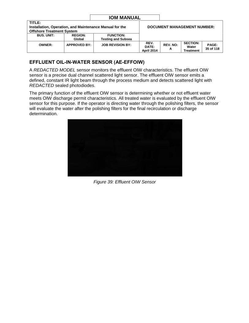
POLISHING FILTERS
The polishing filters provide an additional stage of contaminant removal in case EC treatment, polymer additive, the IAF stage, and bag filters fail to remove the required amount of oil. The polishing filters are treated with a patented molecule integrated into the filter media that exhibits high chemical affinity to hydrocarbon molecules. This affinity binds and coagulates oils and semi-volatile organics into a water-repellant mass, enabling efficient oil capture. The polishing filters are manually introduced into the treatment train with switches on the EC control panel.
Figure 38: Polishing Filters
IOM MANUAL TITLE: Installation, Operation, and Maintenance Manual for the Offshore Treatment System
DOCUMENT MANAGEMENT NUMBER:
BUS. UNIT:
REGION:
Global FUNCTION:
Testing and Subsea
OWNER:
APPROVED BY:
JOB REVISION BY:
REV. DATE:
April 2014
REV. NO: A
SECTION: Water
Treatment
PAGE: 35 of 118
EFFLUENT OIL-IN-WATER SENSOR (AE-EFFOIW)
A REDACTED MODEL sensor monitors the effluent OIW characteristics. The effluent OIW sensor is a precise dual channel scattered light sensor. The effluent OIW sensor emits a defined, constant IR light beam through the process medium and detects scattered light with REDACTED sealed photodiodes.
The primary function of the effluent OIW sensor is determining whether or not effluent water meets OIW discharge permit characteristics. All treated water is evaluated by the effluent OIW sensor for this purpose. If the operator is directing water through the polishing filters, the sensor will evaluate the water after the polishing filters for the final recirculation or discharge determination.
Figure 39: Effluent OIW Sensor
IOM MANUAL TITLE: Installation, Operation, and Maintenance Manual for the Offshore Treatment System
DOCUMENT MANAGEMENT NUMBER:
BUS. UNIT:
REGION:
Global FUNCTION:
Testing and Subsea
OWNER:
APPROVED BY:
JOB REVISION BY:
REV. DATE:
April 2014
REV. NO: A
SECTION: Water
Treatment
PAGE: 36 of 118
SECTION 4 - SETUP AND INSTALLATION
The following section describes set up and installation instructions for the treatment system. Observe the following guidelines when installing the system:
Place the EC unit and IAF unit close enough to allow all electrical and hydraulic interconnections to reach their corresponding points of contact. The most likely distance limiting factor is the 18 m (59 ft.) interconnect cable that runs from the IAF control panel to the signals junction box in the EC unit recess.
Use the provided slings to lift the units with a suitably rated crane.
Keep power disconnects in the OFF position and keep water source isolation valves closed until the system is ready to operate.
Note: Ship and installation facilities, layouts, and resources differ. Consult a site supervisor or other authorized personnel before moving or installing the treatment system.
WARNING: Only qualified personnel should attempt to move, install, or connect power to the treatment system. Observe all applicable safety regulations when moving or installing the system.
PHYSICAL INSTALLATION (ADJACENT)
1. Secure the unit to the installation deck or base by one of the following methods:
a. Use the sacrificial plates, shown in Figure 40, provided at the bottom of each unit for a welded installation.
Figure 40: Sacrificial Plates IAF (Left) and EC (Right)
b. Lock the unit ISO blocks in place using twistlocks or a similar fastener.
c. Clamp the frame to a suitable mounting point.
d. Other approved methods according to ship or installation standards.
PHYSICAL INSTALLATION (STACKED)
1. Insert ISO block locking mechanisms such as twistlocks into the ISO blocks at either the top of the IAF skid or the bottom of the EC unit.

IOM MANUAL TITLE: Installation, Operation, and Maintenance Manual for the Offshore Treatment System
DOCUMENT MANAGEMENT NUMBER:
BUS. UNIT:
REGION:
Global FUNCTION:
Testing and Subsea
OWNER:
APPROVED BY:
JOB REVISION BY:
REV. DATE:
April 2014
REV. NO: A
SECTION: Water
Treatment
PAGE: 37 of 118
2. Secure the IAF skid to the installation deck or base according to the approved facility
installation procedures.
3. Lift the EC unit with a crane and place it on top of the IAF skid. Align the ISO blocks so the twistlocks can function properly.
4. Secure the two units together with the ISO block locking mechanisms.
5. Install the stairs and escape hatch ladder. Lift the stairs and ladder with a crane and secure them to the IAF skid using the attached mounting brackets and pins as shown in Figure 41 and Figure 42.
Figure 41: Stairway Installation
IOM MANUAL TITLE: Installation, Operation, and Maintenance Manual for the Offshore Treatment System
DOCUMENT MANAGEMENT NUMBER:
BUS. UNIT:
REGION:
Global FUNCTION:
Testing and Subsea
OWNER:
APPROVED BY:
JOB REVISION BY:
REV. DATE:
April 2014
REV. NO: A
SECTION: Water
Treatment
PAGE: 38 of 118
Figure 42: Ladder Installation
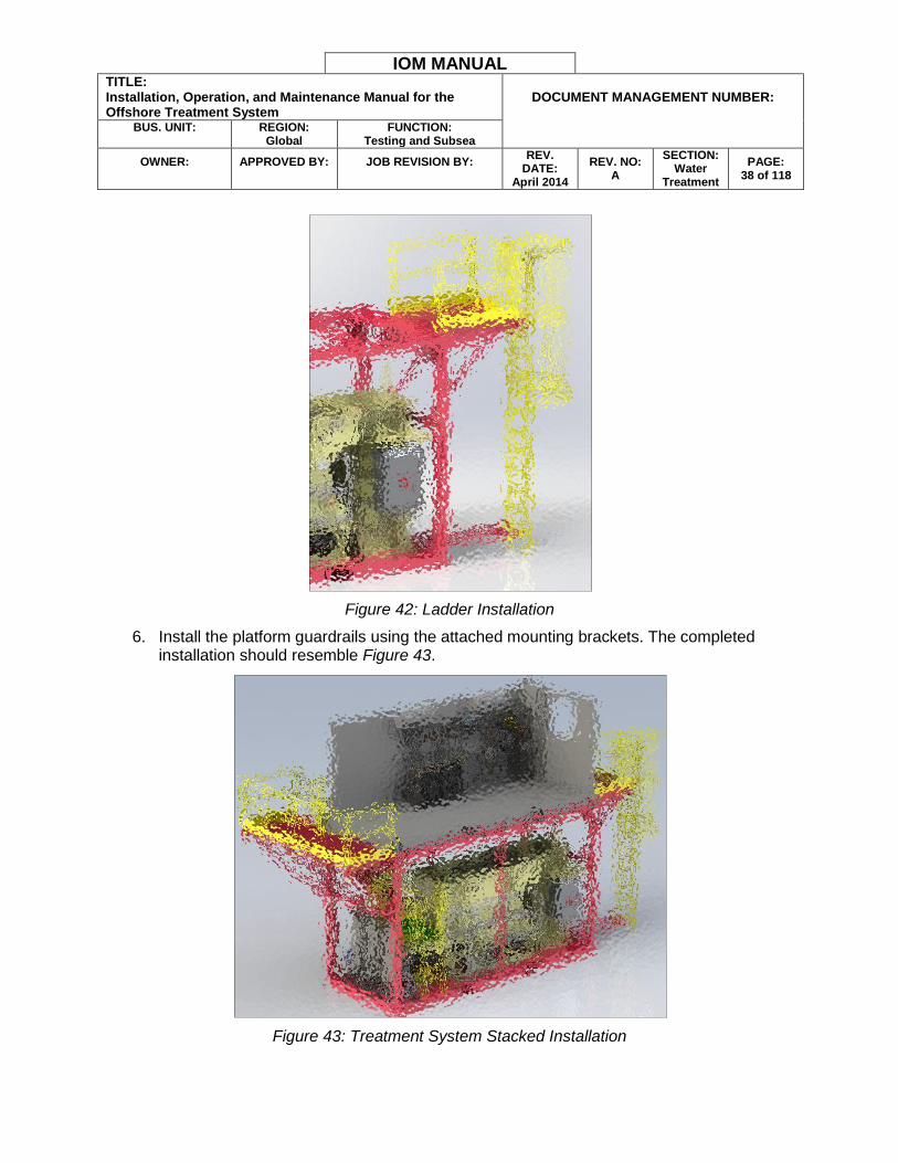
6. Install the platform guardrails using the attached mounting brackets. The completed installation should resemble Figure 43.
Figure 43: Treatment System Stacked Installation
IOM MANUAL TITLE: Installation, Operation, and Maintenance Manual for the Offshore Treatment System
DOCUMENT MANAGEMENT NUMBER:
BUS. UNIT:
REGION:
Global FUNCTION:
Testing and Subsea
OWNER:
APPROVED BY:
JOB REVISION BY:
REV. DATE:
April 2014
REV. NO: A
SECTION: Water
Treatment
PAGE: 39 of 118
CONNECTING POWER, WATER, AND AIR
1. Ensure the source power connection is disconnected. Follow all lockout/tagout electrical safety procedures to ensure power is not unexpectedly supplied to the system.
2. Verify the three-phase source input power is REDACTED VAC with a maximum current of REDACTED A for EC, REDACTED A for IAF prior to connecting the EC and IAF units.
3. Move to the IAF unit. Remove the armored shipboard power cable from the storage position on the side of clearwell #2.
4. Have a qualified electrician connect the IAF unit power cable to the ship or installation power source.
5. Install the IAF cover, if necessary. Connect all grounding cables.
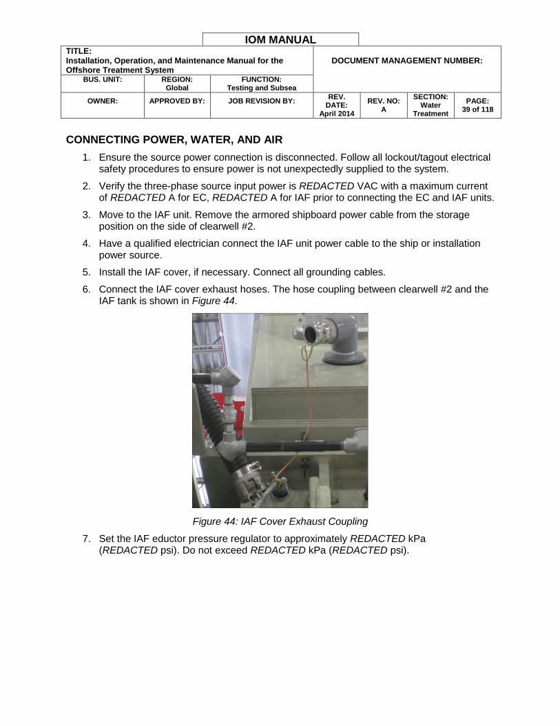
6. Connect the IAF cover exhaust hoses. The hose coupling between clearwell #2 and the IAF tank is shown in Figure 44.
Figure 44: IAF Cover Exhaust Coupling
7. Set the IAF eductor pressure regulator to approximately REDACTED kPa (REDACTED psi). Do not exceed REDACTED kPa (REDACTED psi).
IOM MANUAL TITLE: Installation, Operation, and Maintenance Manual for the Offshore Treatment System
DOCUMENT MANAGEMENT NUMBER:
BUS. UNIT:
REGION:
Global FUNCTION:
Testing and Subsea
OWNER:
APPROVED BY:
JOB REVISION BY:
REV. DATE:
April 2014
REV. NO: A
SECTION: Water
Treatment
PAGE: 40 of 118
Figure 45: IAF Eductor Pressure Regulator
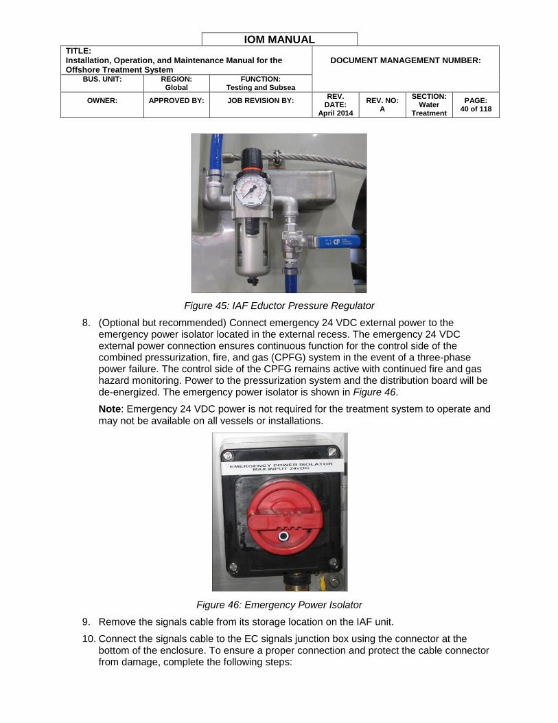
8. (Optional but recommended) Connect emergency 24 VDC external power to the emergency power isolator located in the external recess. The emergency 24 VDC external power connection ensures continuous function for the control side of the combined pressurization, fire, and gas (CPFG) system in the event of a three-phase power failure. The control side of the CPFG remains active with continued fire and gas hazard monitoring. Power to the pressurization system and the distribution board will be de-energized. The emergency power isolator is shown in Figure 46.
Note: Emergency 24 VDC power is not required for the treatment system to operate and may not be available on all vessels or installations.
Figure 46: Emergency Power Isolator
9. Remove the signals cable from its storage location on the IAF unit.
10. Connect the signals cable to the EC signals junction box using the connector at the bottom of the enclosure. To ensure a proper connection and protect the cable connector from damage, complete the following steps:
IOM MANUAL TITLE: Installation, Operation, and Maintenance Manual for the Offshore Treatment System
DOCUMENT MANAGEMENT NUMBER:
BUS. UNIT:
REGION:
Global FUNCTION:
Testing and Subsea
OWNER:
APPROVED BY:
JOB REVISION BY:
REV. DATE:
April 2014
REV. NO: A
SECTION: Water
Treatment
PAGE: 41 of 118
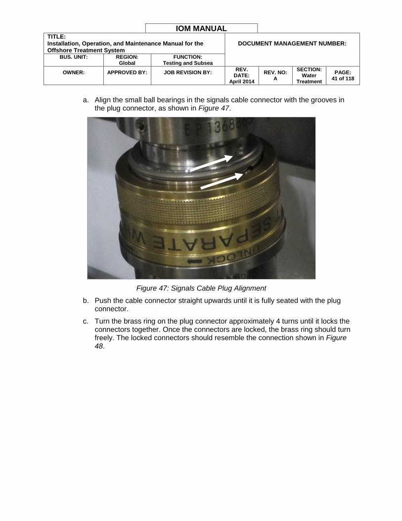
a. Align the small ball bearings in the signals cable connector with the grooves in
the plug connector, as shown in Figure 47.
Figure 47: Signals Cable Plug Alignment
b. Push the cable connector straight upwards until it is fully seated with the plug connector.
c. Turn the brass ring on the plug connector approximately 4 turns until it locks the connectors together. Once the connectors are locked, the brass ring should turn freely. The locked connectors should resemble the connection shown in Figure 48.
IOM MANUAL TITLE: Installation, Operation, and Maintenance Manual for the Offshore Treatment System
DOCUMENT MANAGEMENT NUMBER:
BUS. UNIT:
REGION:
Global FUNCTION:
Testing and Subsea
OWNER:
APPROVED BY:
JOB REVISION BY:
REV. DATE:
April 2014
REV. NO: A
SECTION: Water
Treatment
PAGE: 42 of 118
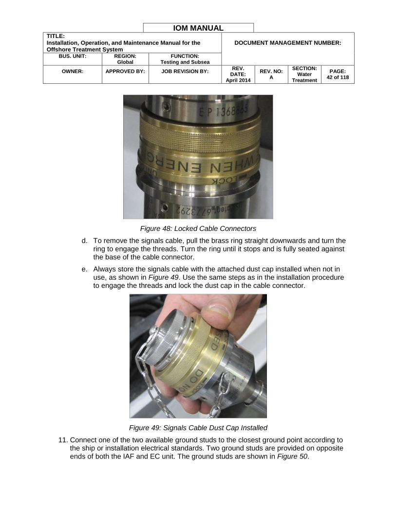
Figure 48: Locked Cable Connectors
d. To remove the signals cable, pull the brass ring straight downwards and turn the ring to engage the threads. Turn the ring until it stops and is fully seated against the base of the cable connector.
e. Always store the signals cable with the attached dust cap installed when not in use, as shown in Figure 49. Use the same steps as in the installation procedure to engage the threads and lock the dust cap in the cable connector.
Figure 49: Signals Cable Dust Cap Installed
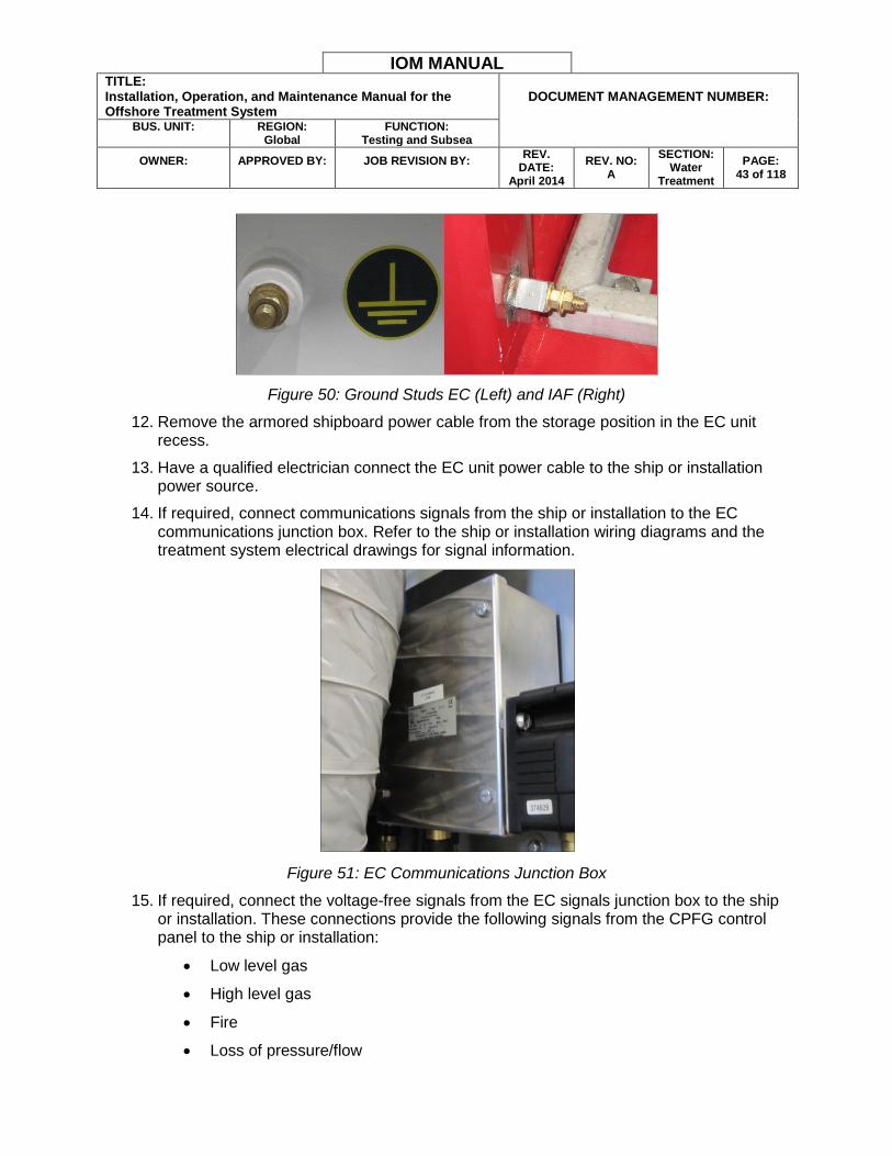
11. Connect one of the two available ground studs to the closest ground point according to the ship or installation electrical standards. Two ground studs are provided on opposite ends of both the IAF and EC unit. The ground studs are shown in Figure 50.
IOM MANUAL TITLE: Installation, Operation, and Maintenance Manual for the Offshore Treatment System
DOCUMENT MANAGEMENT NUMBER:
BUS. UNIT:
REGION:
Global FUNCTION:
Testing and Subsea
OWNER:
APPROVED BY:
JOB REVISION BY:
REV. DATE:
April 2014
REV. NO: A
SECTION: Water
Treatment
PAGE: 43 of 118
Figure 50: Ground Studs EC (Left) and IAF (Right)
12. Remove the armored shipboard power cable from the storage position in the EC unit recess.
13. Have a qualified electrician connect the EC unit power cable to the ship or installation power source.
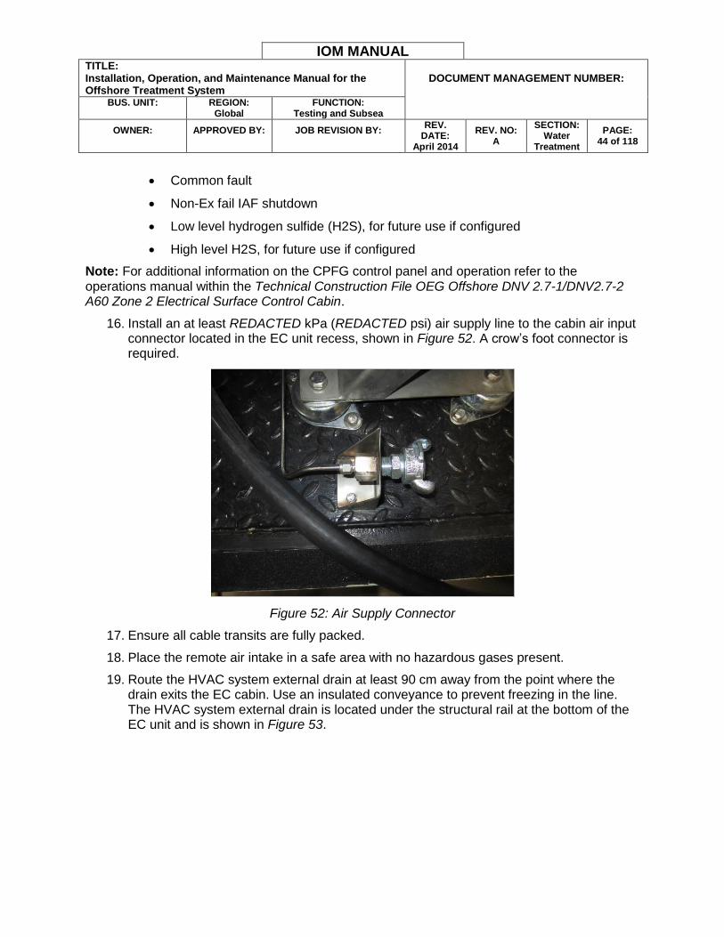
14. If required, connect communications signals from the ship or installation to the EC communications junction box. Refer to the ship or installation wiring diagrams and the treatment system electrical drawings for signal information.
Figure 51: EC Communications Junction Box
15. If required, connect the voltage-free signals from the EC signals junction box to the ship or installation. These connections provide the following signals from the CPFG control panel to the ship or installation:
Low level gas
High level gas
Fire
Loss of pressure/flow
IOM MANUAL TITLE: Installation, Operation, and Maintenance Manual for the Offshore Treatment System
DOCUMENT MANAGEMENT NUMBER:
BUS. UNIT:
REGION:
Global FUNCTION:
Testing and Subsea
OWNER:
APPROVED BY:
JOB REVISION BY:
REV. DATE:
April 2014
REV. NO: A
SECTION: Water
Treatment
PAGE: 44 of 118
Common fault
Non-Ex fail IAF shutdown
Low level hydrogen sulfide (H2S), for future use if configured
High level H2S, for future use if configured
Note: For additional information on the CPFG control panel and operation refer to the operations manual within the Technical Construction File OEG Offshore DNV 2.7-1/DNV2.7-2 A60 Zone 2 Electrical Surface Control Cabin.
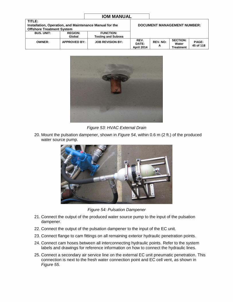
16. Install an at least REDACTED kPa (REDACTED psi) air supply line to the cabin air input connector located in the EC unit recess, shown in Figure 52. A crow’s foot connector is required.
Figure 52: Air Supply Connector
17. Ensure all cable transits are fully packed.
18. Place the remote air intake in a safe area with no hazardous gases present.
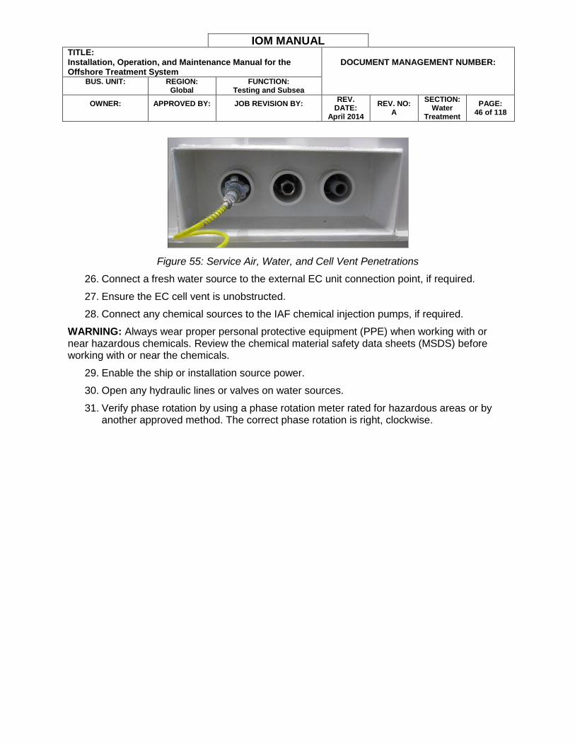
19. Route the HVAC system external drain at least 90 cm away from the point where the drain exits the EC cabin. Use an insulated conveyance to prevent freezing in the line. The HVAC system external drain is located under the structural rail at the bottom of the EC unit and is shown in Figure 53.
IOM MANUAL TITLE: Installation, Operation, and Maintenance Manual for the Offshore Treatment System
DOCUMENT MANAGEMENT NUMBER:
BUS. UNIT:
REGION:
Global FUNCTION:
Testing and Subsea
OWNER:
APPROVED BY:
JOB REVISION BY:
REV. DATE:
April 2014
REV. NO: A
SECTION: Water
Treatment
PAGE: 45 of 118
Figure 53: HVAC External Drain
20. Mount the pulsation dampener, shown in Figure 54, within 0.6 m (2 ft.) of the produced water source pump.
Figure 54: Pulsation Dampener
21. Connect the output of the produced water source pump to the input of the pulsation dampener.
22. Connect the output of the pulsation dampener to the input of the EC unit.
23. Connect flange to cam fittings on all remaining exterior hydraulic penetration points.
24. Connect cam hoses between all interconnecting hydraulic points. Refer to the system labels and drawings for reference information on how to connect the hydraulic lines.
25. Connect a secondary air service line on the external EC unit pneumatic penetration. This connection is next to the fresh water connection point and EC cell vent, as shown in Figure 55.
IOM MANUAL TITLE: Installation, Operation, and Maintenance Manual for the Offshore Treatment System
DOCUMENT MANAGEMENT NUMBER:
BUS. UNIT:
REGION:
Global FUNCTION:
Testing and Subsea
OWNER:
APPROVED BY:
JOB REVISION BY:
REV. DATE:
April 2014
REV. NO: A
SECTION: Water
Treatment
PAGE: 46 of 118
Figure 55: Service Air, Water, and Cell Vent Penetrations
26. Connect a fresh water source to the external EC unit connection point, if required.
27. Ensure the EC cell vent is unobstructed.
28. Connect any chemical sources to the IAF chemical injection pumps, if required.
WARNING: Always wear proper personal protective equipment (PPE) when working with or near hazardous chemicals. Review the chemical material safety data sheets (MSDS) before working with or near the chemicals.
29. Enable the ship or installation source power.
30. Open any hydraulic lines or valves on water sources.
31. Verify phase rotation by using a phase rotation meter rated for hazardous areas or by another approved method. The correct phase rotation is right, clockwise.
IOM MANUAL TITLE: Installation, Operation, and Maintenance Manual for the Offshore Treatment System
DOCUMENT MANAGEMENT NUMBER:
BUS. UNIT:
REGION:
Global FUNCTION:
Testing and Subsea
OWNER:
APPROVED BY:
JOB REVISION BY:
REV. DATE:
April 2014
REV. NO: A
SECTION: Water
Treatment
PAGE: 47 of 118
SECTION 5 - OPERATION
The following sections describe the treatment system operational procedures.
EC STARTUP PROCEDURE
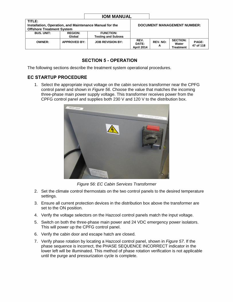
1. Select the appropriate input voltage on the cabin services transformer near the CPFG control panel and shown in Figure 56. Choose the value that matches the incoming three-phase main power supply voltage. This transformer receives power from the CPFG control panel and supplies both 230 V and 120 V to the distribution box.
Figure 56: EC Cabin Services Transformer
2. Set the climate control thermostats on the two control panels to the desired temperature settings.
3. Ensure all current protection devices in the distribution box above the transformer are set to the ON position.
4. Verify the voltage selectors on the Hazcool control panels match the input voltage.
5. Switch on both the three-phase main power and 24 VDC emergency power isolators. This will power up the CPFG control panel.
6. Verify the cabin door and escape hatch are closed.
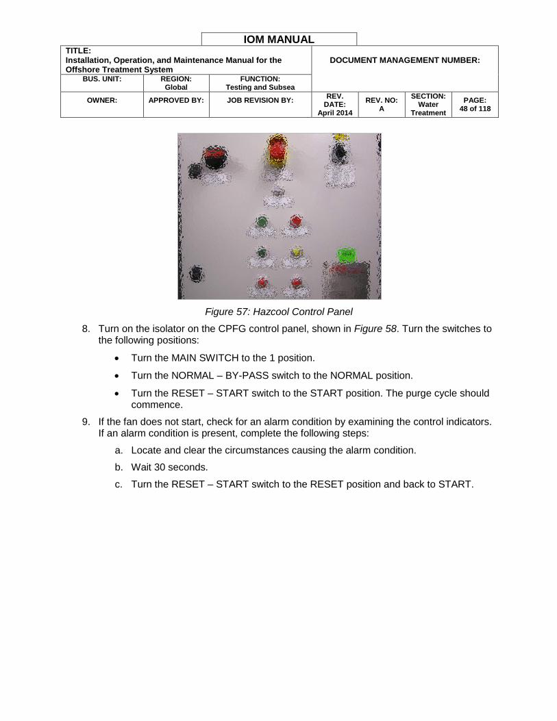
7. Verify phase rotation by locating a Hazcool control panel, shown in Figure 57. If the phase sequence is incorrect, the PHASE SEQUENCE INCORRECT indicator in the lower left will be illuminated. This method of phase rotation verification is not applicable until the purge and pressurization cycle is complete.
IOM MANUAL TITLE: Installation, Operation, and Maintenance Manual for the Offshore Treatment System
DOCUMENT MANAGEMENT NUMBER:
BUS. UNIT:
REGION:
Global FUNCTION:
Testing and Subsea
OWNER:
APPROVED BY:
JOB REVISION BY:
REV. DATE:
April 2014
REV. NO: A
SECTION: Water
Treatment
PAGE: 48 of 118
Figure 57: Hazcool Control Panel
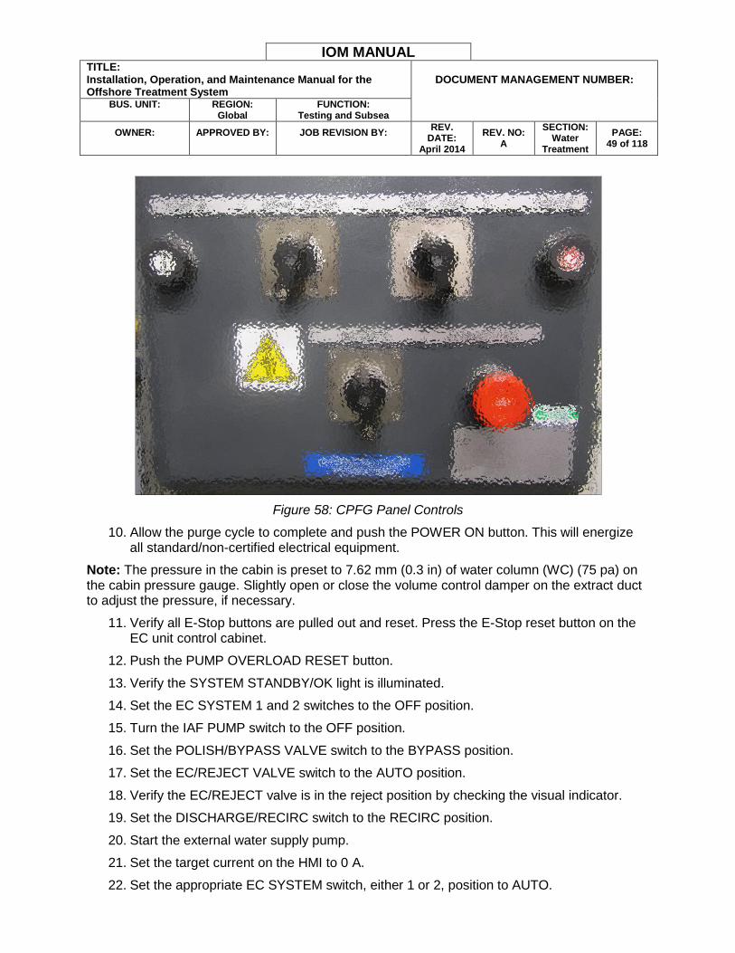
8. Turn on the isolator on the CPFG control panel, shown in Figure 58. Turn the switches to the following positions:
Turn the MAIN SWITCH to the 1 position.
Turn the NORMAL – BY-PASS switch to the NORMAL position.
Turn the RESET – START switch to the START position. The purge cycle should commence.
9. If the fan does not start, check for an alarm condition by examining the control indicators. If an alarm condition is present, complete the following steps:
a. Locate and clear the circumstances causing the alarm condition.
b. Wait 30 seconds.
c. Turn the RESET – START switch to the RESET position and back to START.
IOM MANUAL TITLE: Installation, Operation, and Maintenance Manual for the Offshore Treatment System
DOCUMENT MANAGEMENT NUMBER:
BUS. UNIT:
REGION:
Global FUNCTION:
Testing and Subsea
OWNER:
APPROVED BY:
JOB REVISION BY:
REV. DATE:
April 2014
REV. NO: A
SECTION: Water
Treatment
PAGE: 49 of 118
Figure 58: CPFG Panel Controls
10. Allow the purge cycle to complete and push the POWER ON button. This will energize all standard/non-certified electrical equipment.
Note: The pressure in the cabin is preset to 7.62 mm (0.3 in) of water column (WC) (75 pa) on the cabin pressure gauge. Slightly open or close the volume control damper on the extract duct to adjust the pressure, if necessary.
11. Verify all E-Stop buttons are pulled out and reset. Press the E-Stop reset button on the EC unit control cabinet.
12. Push the PUMP OVERLOAD RESET button.
13. Verify the SYSTEM STANDBY/OK light is illuminated.
14. Set the EC SYSTEM 1 and 2 switches to the OFF position.
15. Turn the IAF PUMP switch to the OFF position.
16. Set the POLISH/BYPASS VALVE switch to the BYPASS position.
17. Set the EC/REJECT VALVE switch to the AUTO position.
18. Verify the EC/REJECT valve is in the reject position by checking the visual indicator.
19. Set the DISCHARGE/RECIRC switch to the RECIRC position.
20. Start the external water supply pump.
21. Set the target current on the HMI to 0 A.
22. Set the appropriate EC SYSTEM switch, either 1 or 2, position to AUTO.

IOM MANUAL TITLE: Installation, Operation, and Maintenance Manual for the Offshore Treatment System
DOCUMENT MANAGEMENT NUMBER:
BUS. UNIT:
REGION:
Global FUNCTION:
Testing and Subsea
OWNER:
APPROVED BY:
JOB REVISION BY:
REV. DATE:
April 2014
REV. NO: A
SECTION: Water
Treatment
PAGE: 50 of 118
23. Check the system and any connections for leaks.
24. Run the system for one minute to fill the EC cells with water.
25. Set the target current on the HMI to the target treatment current.
26. Turn the following switches to the AUTO position:
IAF PUMP
CLEARWELL PUMP
SLUDGE PUMP
CONE BOTTOM VALVE 1
CONE BOTTOM VALVE 2
SCRAPER MOTOR
27. Run the system for a few minutes and observe the pressure on the PI-01 SUPPLY PRESSURE gauge. Stop the system.
28. Set the pulsation dampener preload pressure to approximately 80% of the pressure reading observed on the PI-01 SUPPLY PRESSURE gauge. The pulsation dampener preload pressure is the pressure shown on the dampener gauge with the system not in operation. To adjust the preload pressure, either add or remove air from the pulsation dampener valve shown in Figure 59.
WARNING: Failure to properly set the preload pressure on the pulsation dampener could result in the EC unit conveyance pipes vibrating or shaking. When the system is properly configured, the pulsation dampener should shake and vibrate while the EC unit pipes remain still.
Figure 59: Pulsation Dampener Preload Pressure Adjustment Valve
29. Restart the system.
30. If required, turn the chemical injection pump switches on the IAF control panel to AUTO.

IOM MANUAL TITLE: Installation, Operation, and Maintenance Manual for the Offshore Treatment System
DOCUMENT MANAGEMENT NUMBER:
BUS. UNIT:
REGION:
Global FUNCTION:
Testing and Subsea
OWNER:
APPROVED BY:
JOB REVISION BY:
REV. DATE:
April 2014
REV. NO: A
SECTION: Water
Treatment
PAGE: 51 of 118
31. Adjust the chemical injection rate on the chemical injection pump. Refer to the
CHEMICAL INJECTION OPERATION for details on finding the appropriate injection rate.
32. Take a water sample from the sample port prior to the effluent OIW sensor.
33. Perform a Wilks test on the water sample to verify the OIW level is below the discharge limit. Refer to the OIW LEVEL WILKS TEST section for more information.
34. Verify the OIW level from the Wilks test matches the OIW level reported on the OIL IN WATER display on the EC control panel.
35. If necessary, after adjusting chemical injection and checking the OIW level, set the POLISH/BYPASS VALVE to POLISH. Open the manual hydraulic valves that control access to the polishing filter.
36. Set the EC/REJECT VALVE switch position to AUTO.
37. Set the DISCHARGE/RECIRC switch position to AUTO.
EC OPERATIONAL CONDITIONS
The following section describes operational safeguards for the EC unit.
Differential pressure switches constantly compare pressure within the cabin and atmospheric pressure. If pressurization is lost during operations, an audible alarm will sound. This alarm warns operators that the shutdown timer is running and pressurization must be reestablished quickly, generally in less than 30 seconds. If pressurization is not reestablished, power to all standard electrical equipment is disconnected. The cabin must go through the complete purge cycle again before power is supplied to the non-certified electrical equipment.
Two Ex-certified gas detectors, one internal and one external, detect any gas entering the cabin. If either detector registers a low-level gas alarm at 10% lower explosive limit (LEL), the system will sound an audible alarm. If high level gas (20% LEL) is detected within the cabin, all power to non-certified electrical equipment is disabled, the pressurization fan will stop, and the fire dampers will close. An audible alarm will also sound and a visual alarm indication will appear on the CPFG display. The EC unit is also capable of H2S detection with additional configuration.
There are two certified intrinsically safe (IS) smoke detectors within the cabin- one in the transfer area and another in the main area. The smoke detectors will disable power to all non-certified equipment within the cabin in case of fire. In addition to the smoke detectors, an IS manual alarm call point can be activated from within the transfer area. This call point will also disable power to all non-certified equipment. If a fire alarm is tripped, an audible alarm will sound and a visual alarm indication will appear on the CPFG display.
If a fire or high gas level shutdown occurs, the operator must reset the switch on the front of the CPFG panel and restart the purge cycle.
IOM MANUAL TITLE: Installation, Operation, and Maintenance Manual for the Offshore Treatment System
DOCUMENT MANAGEMENT NUMBER:
BUS. UNIT:
REGION:
Global FUNCTION:
Testing and Subsea
OWNER:
APPROVED BY:
JOB REVISION BY:
REV. DATE:
April 2014
REV. NO: A
SECTION: Water
Treatment
PAGE: 52 of 118
IAF OPERATION
This section describes how to operate the IAF unit.
Note: Protect the IAF unit from freezing conditions when water is present to prevent iceexpansion from damaging the unit. Do not supply the IAF unit with water exceeding REDACTED °C (REDACTED °F).
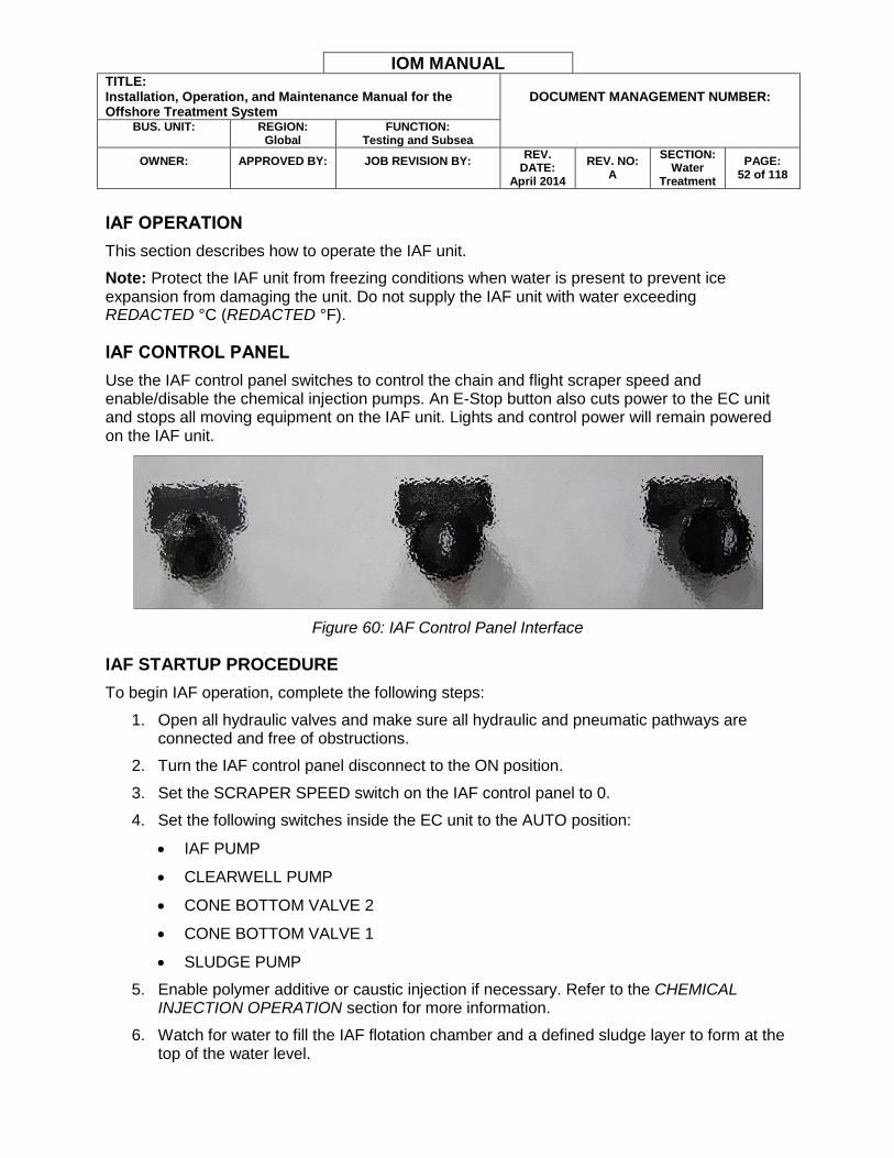
IAF CONTROL PANEL
Use the IAF control panel switches to control the chain and flight scraper speed and enable/disable the chemical injection pumps. An E-Stop button also cuts power to the EC unit and stops all moving equipment on the IAF unit. Lights and control power will remain powered on the IAF unit.
Figure 60: IAF Control Panel Interface
IAF STARTUP PROCEDURE
To begin IAF operation, complete the following steps:
1. Open all hydraulic valves and make sure all hydraulic and pneumatic pathways are connected and free of obstructions.
2. Turn the IAF control panel disconnect to the ON position.
3. Set the SCRAPER SPEED switch on the IAF control panel to 0.
4. Set the following switches inside the EC unit to the AUTO position:
IAF PUMP
CLEARWELL PUMP
CONE BOTTOM VALVE 2
CONE BOTTOM VALVE 1
SLUDGE PUMP
5. Enable polymer additive or caustic injection if necessary. Refer to the CHEMICAL INJECTION OPERATION section for more information.
6. Watch for water to fill the IAF flotation chamber and a defined sludge layer to form at the top of the water level.
IOM MANUAL TITLE: Installation, Operation, and Maintenance Manual for the Offshore Treatment System
DOCUMENT MANAGEMENT NUMBER:
BUS. UNIT:
REGION:
Global FUNCTION:
Testing and Subsea
OWNER:
APPROVED BY:
JOB REVISION BY:
REV. DATE:
April 2014
REV. NO: A
SECTION: Water
Treatment
PAGE: 53 of 118
7. Turn the SCRAPER MOTOR switch in the EC unit to the AUTO position.
8. Proceed to the IAF UNIT OPERATION TUNING section for details on how to enhance IAF unit performance.
IAF UNIT OPERATION TUNING
The following sections describe methods to tune IAF unit operation.
General Guidelines
The following recommendations will help the IAF unit and treatment system operate more smoothly and efficiently.
The IAF has no minimum flow rate. The maximum flow rate depends on the level of water contamination and the effectiveness of the EC treatment and polymer injection. The designed maximum flow rate through the IAF unit is REDACTED liters per minute.
Run the clearwell pump slightly faster than the influent flow rate. An increase of 3-4 liters (approximately one gallon) per minute in the clearwell pump flow rate over the EC treatment flow will help reduce the number of times the clearwell pump must cycle power.
Clean sealed chambers including the bubble separator chambers and dispersal pipes regularly. Access ports provide access for brushes, hoses, and other equipment to remove buildup and flow restrictions.
IAF Pump Operation
The IAF pump produces whitewater by taking a portion of the effluent treated water from IAF clearwell #1 and saturating it with atmospheric air. Check the following conditions regularly to ensure the IAF pump is operating efficiently:
Verify the vacuum gauge measures approximately REDACTED inches of mercury (inHg).
Observe the sight glass. Ensure large air bubbles are leaving the whitewater chamber without an excessive, continuous water flow.
Verify the injection pressure is approximately REDACTED kPa (REDACTED psi) using the PI-04 BUBBLE SEP CHAMBER PRESS gauge.
Properly regulating the vacuum suction pressure and discharge injection pressure ensures the correct size and amount of fine air bubbles will dissolve into the whitewater. Four injection points inject the whitewater into the water stream. At each of these points, a ball valve (V26 – V29) is installed to regulate the discharge pressure, as shown in Figure 61.

IOM MANUAL TITLE: Installation, Operation, and Maintenance Manual for the Offshore Treatment System
DOCUMENT MANAGEMENT NUMBER:
BUS. UNIT:
REGION:
Global FUNCTION:
Testing and Subsea
OWNER:
APPROVED BY:
JOB REVISION BY:
REV. DATE:
April 2014
REV. NO: A
SECTION: Water
Treatment
PAGE: 54 of 118
Figure 61: Whitewater Injection Points
The optimum air distribution between the four injection points is determined at start up and may require minor adjustments during the first few weeks of IAF operation.
Weir Pipe and Water Extraction Introduction
The adjustable weir pipe system allows the operator to control the water level in the separation portion of the IAF unit. The operator can control the content and thickness of the top sludge by adjusting the water level within the separation zone. For example, the operator can adjust the weir pipes down to create a drier top sludge or up to raise the water level and raise the top sludge water content.
The IAF unit incorporates a proprietary progressive water extraction (PWE) design. This design increases the separation time for the finer solids maximizing liquid/solids separation performance. The process is controlled by adjusting the individual weir pipes. The operator can set the weir pipes at individual levels to extract water from the desired area of the system. The more water removed from the weir pipe nearest the IAF influent wall, the more time the remaining water has to separate from contaminants. The IAF influent wall is the wall on the right side while looking into the IAF flotation chamber from the raised platform. Stokes’ Law and Brownian motion dictate that finer particles require more detention time. Removing clean water from the system as soon as possible effectively provides more time for the remaining water slurry to separate. An operator can demonstrate this by performing a wastewater jar test.
Weir Pipe Adjustment
Each site can generate wastewater with different characteristics. Keeping the weir pipes properly adjusted and testing the adjustment performance is essential to efficient system operation. One of the first signs that the IAF system is not efficiently removing pollutants is dirty water entering clearwell #1. There are two remediation steps if dirty water is entering clearwell #1. The operator can slow the entire system flow rate to allow more water residence time or adjust the weir pipe configuration. To test and adjust the weir pipe configuration, complete the following steps:
IOM MANUAL TITLE: Installation, Operation, and Maintenance Manual for the Offshore Treatment System
DOCUMENT MANAGEMENT NUMBER:
BUS. UNIT:
REGION:
Global FUNCTION:
Testing and Subsea
OWNER:
APPROVED BY:
JOB REVISION BY:
REV. DATE:
April 2014
REV. NO: A
SECTION: Water
Treatment
PAGE: 55 of 118
1. Obtain a jar sample from the top of each weir pipe. Hold a jar or beaker in clearwell #1
and collect water spilling over the top of each weir pipe in three separate containers.
2. Observe each weir pipe sample. Note which sample appears the most polluted.
3. Slightly raise the weir pipe that returned the most polluted sample. Alternatively, the operator may slightly lower the weir pipes that returned cleaner samples. The principle behind these two approaches is to increase the outflow of clean water from the system while slowing dirtier water and allowing it more residence and treatment time.
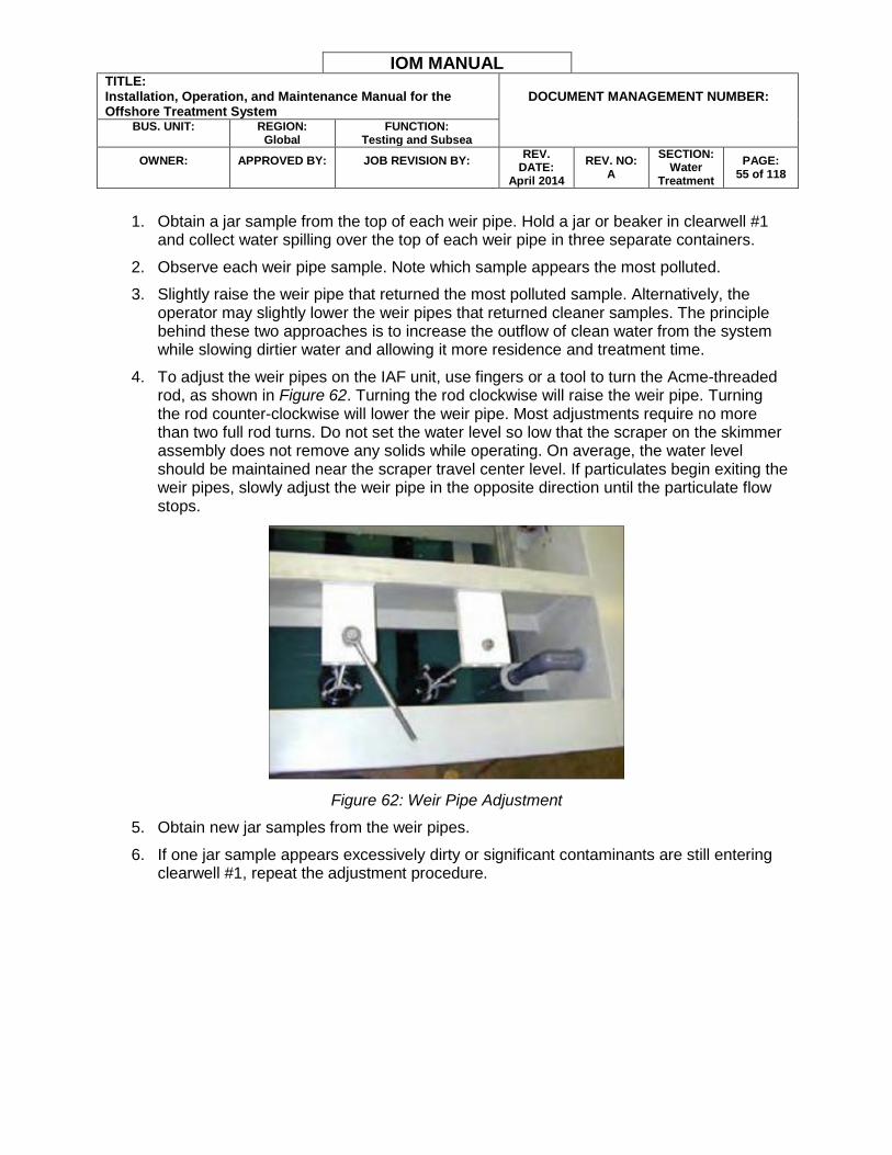
4. To adjust the weir pipes on the IAF unit, use fingers or a tool to turn the Acme-threaded rod, as shown in Figure 62. Turning the rod clockwise will raise the weir pipe. Turning the rod counter-clockwise will lower the weir pipe. Most adjustments require no more than two full rod turns. Do not set the water level so low that the scraper on the skimmer assembly does not remove any solids while operating. On average, the water level should be maintained near the scraper travel center level. If particulates begin exiting the weir pipes, slowly adjust the weir pipe in the opposite direction until the particulate flow stops.
Figure 62: Weir Pipe Adjustment
5. Obtain new jar samples from the weir pipes.
6. If one jar sample appears excessively dirty or significant contaminants are still entering clearwell #1, repeat the adjustment procedure.
IOM MANUAL TITLE: Installation, Operation, and Maintenance Manual for the Offshore Treatment System
DOCUMENT MANAGEMENT NUMBER:
BUS. UNIT:
REGION:
Global FUNCTION:
Testing and Subsea
OWNER:
APPROVED BY:
JOB REVISION BY:
REV. DATE:
April 2014
REV. NO: A
SECTION: Water
Treatment
PAGE: 56 of 118
HMI INTERFACE SCREENS
The following sections describe the HMI interface. The HMI is the main point of configuration, control, and monitoring for the treatment system.
System Page
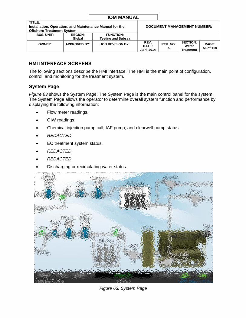
Figure 63 shows the System Page. The System Page is the main control panel for the system. The System Page allows the operator to determine overall system function and performance by displaying the following information:
Flow meter readings.
OIW readings.
Chemical injection pump call, IAF pump, and clearwell pump status.
REDACTED.
EC treatment system status.
REDACTED.
REDACTED.
Discharging or recirculating water status.
Figure 63: System Page
IOM MANUAL TITLE: Installation, Operation, and Maintenance Manual for the Offshore Treatment System
DOCUMENT MANAGEMENT NUMBER:
BUS. UNIT:
REGION:
Global FUNCTION:
Testing and Subsea
OWNER:
APPROVED BY:
JOB REVISION BY:
REV. DATE:
April 2014
REV. NO: A
SECTION: Water
Treatment
PAGE: 57 of 118
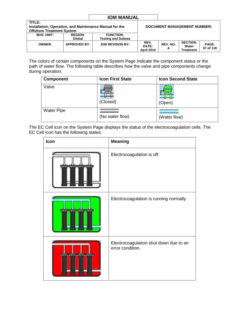
The colors of certain components on the System Page indicate the component status or the path of water flow. The following table describes how the valve and pipe components change during operation.
Component Icon First State Icon Second State
Valve
(Closed)
(Open)
Water Pipe (No water flow)
(Water flow)
The EC Cell icon on the System Page displays the status of the electrocoagulation cells. The EC Cell icon has the following states:
Icon Meaning
Electrocoagulation is off.
Electrocoagulation is running normally.
Electrocoagulation shut down due to an error condition.
IOM MANUAL TITLE: Installation, Operation, and Maintenance Manual for the Offshore Treatment System
DOCUMENT MANAGEMENT NUMBER:
BUS. UNIT:
REGION:
Global FUNCTION:
Testing and Subsea
OWNER:
APPROVED BY:
JOB REVISION BY:
REV. DATE:
April 2014
REV. NO: A
SECTION: Water
Treatment
PAGE: 58 of 118
The electrocoagulation system is in standby mode.
The System Page indicates the status of all water treatment stages. If there is an error anywhere in the system, the System Page will display Check Alarms text at the bottom of the screen. The operator can investigate the error by tapping the corresponding icon or Check Alarms text.
Pumps Page
Figure 64 shows the Pumps Page. The Pumps Page displays the following information:
Target flow rate.
REDACTED.
EC and IAF supply pump run times.
REDACTED.
Flow totals.
Measurement unit information.
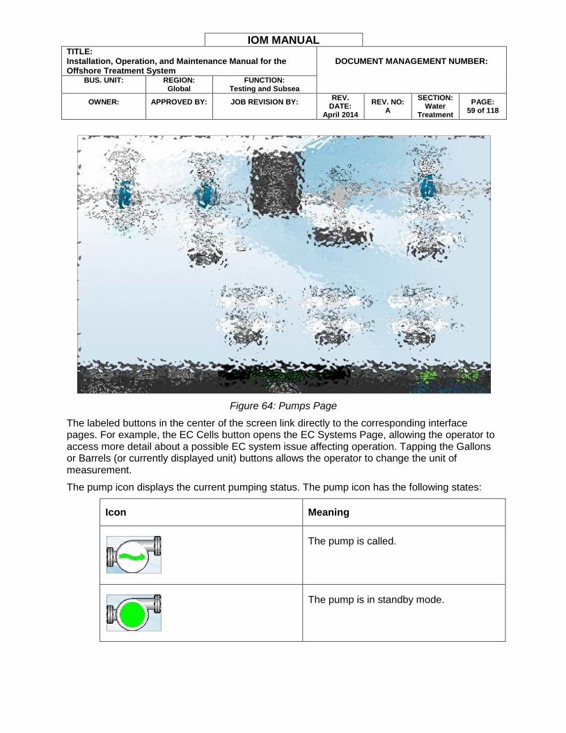
IOM MANUAL TITLE: Installation, Operation, and Maintenance Manual for the Offshore Treatment System
DOCUMENT MANAGEMENT NUMBER:
BUS. UNIT:
REGION:
Global FUNCTION:
Testing and Subsea
OWNER:
APPROVED BY:
JOB REVISION BY:
REV. DATE:
April 2014
REV. NO: A
SECTION: Water
Treatment
PAGE: 59 of 118
Figure 64: Pumps Page
The labeled buttons in the center of the screen link directly to the corresponding interface pages. For example, the EC Cells button opens the EC Systems Page, allowing the operator to access more detail about a possible EC system issue affecting operation. Tapping the Gallons or Barrels (or currently displayed unit) buttons allows the operator to change the unit of measurement.
The pump icon displays the current pumping status. The pump icon has the following states:
Icon Meaning
The pump is called.
The pump is in standby mode.
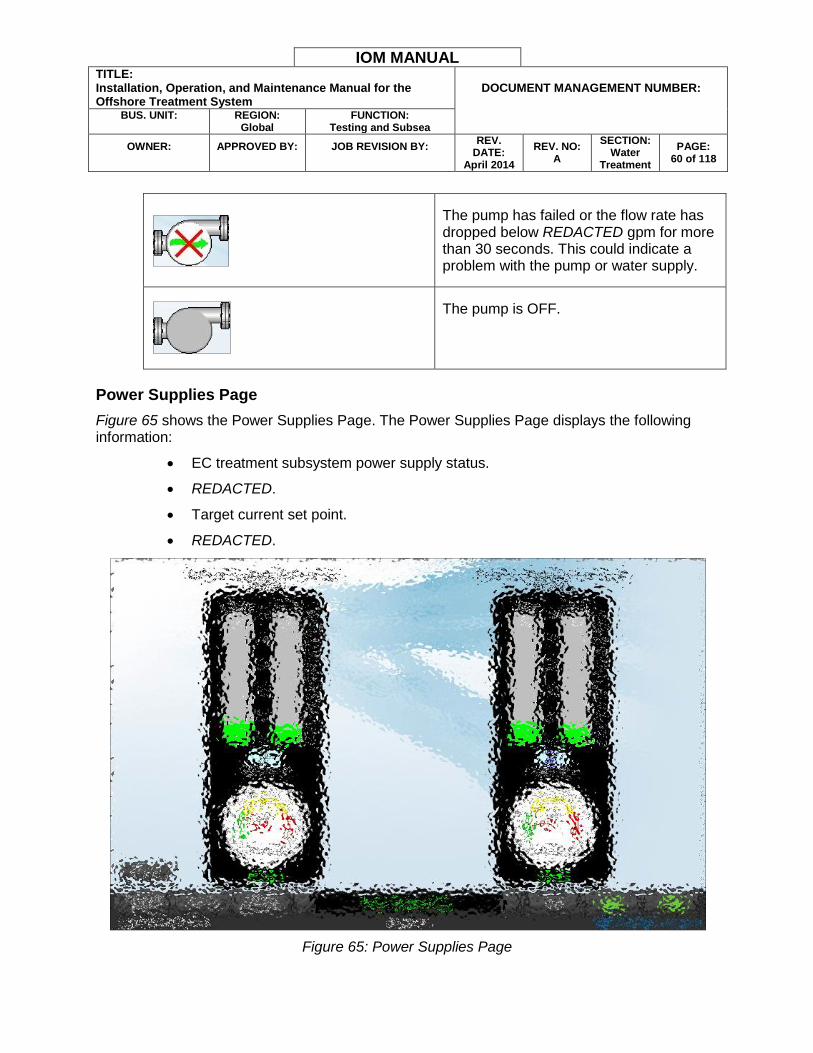
IOM MANUAL TITLE: Installation, Operation, and Maintenance Manual for the Offshore Treatment System
DOCUMENT MANAGEMENT NUMBER:
BUS. UNIT:
REGION:
Global FUNCTION:
Testing and Subsea
OWNER:
APPROVED BY:
JOB REVISION BY:
REV. DATE:
April 2014
REV. NO: A
SECTION: Water
Treatment
PAGE: 60 of 118
The pump has failed or the flow rate has dropped below REDACTED gpm for more than 30 seconds. This could indicate a problem with the pump or water supply.
The pump is OFF.
Power Supplies Page
Figure 65 shows the Power Supplies Page. The Power Supplies Page displays the following information:
EC treatment subsystem power supply status.
REDACTED.
Target current set point.
REDACTED.
Figure 65: Power Supplies Page
IOM MANUAL TITLE: Installation, Operation, and Maintenance Manual for the Offshore Treatment System
DOCUMENT MANAGEMENT NUMBER:
BUS. UNIT:
REGION:
Global FUNCTION:
Testing and Subsea
OWNER:
APPROVED BY:
JOB REVISION BY:
REV. DATE:
April 2014
REV. NO: A
SECTION: Water
Treatment
PAGE: 61 of 118
Press the numeric indicator or the SET ALL button to set the target treatment current. The system will automatically adjust the voltage to achieve the target current setting. The Voltage indicator bar displays the DC voltage supplied to EC cell treatment. The voltage value is measured at the REDACTED in DC volts (VDC). The Current indicator bar displays the DC current passing through the EC cells. The current value is measured at the REDACTED in DC amperes (ADC).
The Cell Resistance indicator displays the EC cell subsystem resistance in ohms. Cell resistance varies due to variations in cell configuration, cell conditions such as fouling or plate consumption, and water conductivity. Cell resistance measurements in conjunction with water conductivity readings are used for estimating cell wear and troubleshooting various issues.
Cell resistance is calculated using Ohm’s law:
𝑅 =𝑉
𝐼
Where:
R is the resistance of the conductor in units of ohms.
V is the potential difference measured across the conductor in units of volts.
I is the current through the conductor in units of amperes.
Figure 66 shows the Power Supplies Page with a current deviation error. A current deviation error occurs when a subsystem cannot meet the target EC treatment current for more than REDACTED seconds. A current deviation error can be a sign of cell wear, cell fouling, consumed plates, low water conductivity, or other electrical issue.
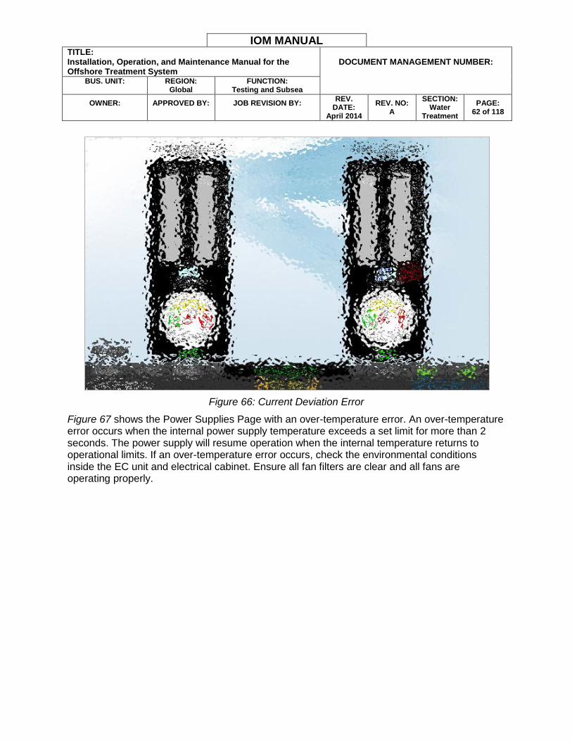
IOM MANUAL TITLE: Installation, Operation, and Maintenance Manual for the Offshore Treatment System
DOCUMENT MANAGEMENT NUMBER:
BUS. UNIT:
REGION:
Global FUNCTION:
Testing and Subsea
OWNER:
APPROVED BY:
JOB REVISION BY:
REV. DATE:
April 2014
REV. NO: A
SECTION: Water
Treatment
PAGE: 62 of 118
Figure 66: Current Deviation Error
Figure 67 shows the Power Supplies Page with an over-temperature error. An over-temperature error occurs when the internal power supply temperature exceeds a set limit for more than 2 seconds. The power supply will resume operation when the internal temperature returns to operational limits. If an over-temperature error occurs, check the environmental conditions inside the EC unit and electrical cabinet. Ensure all fan filters are clear and all fans are operating properly.
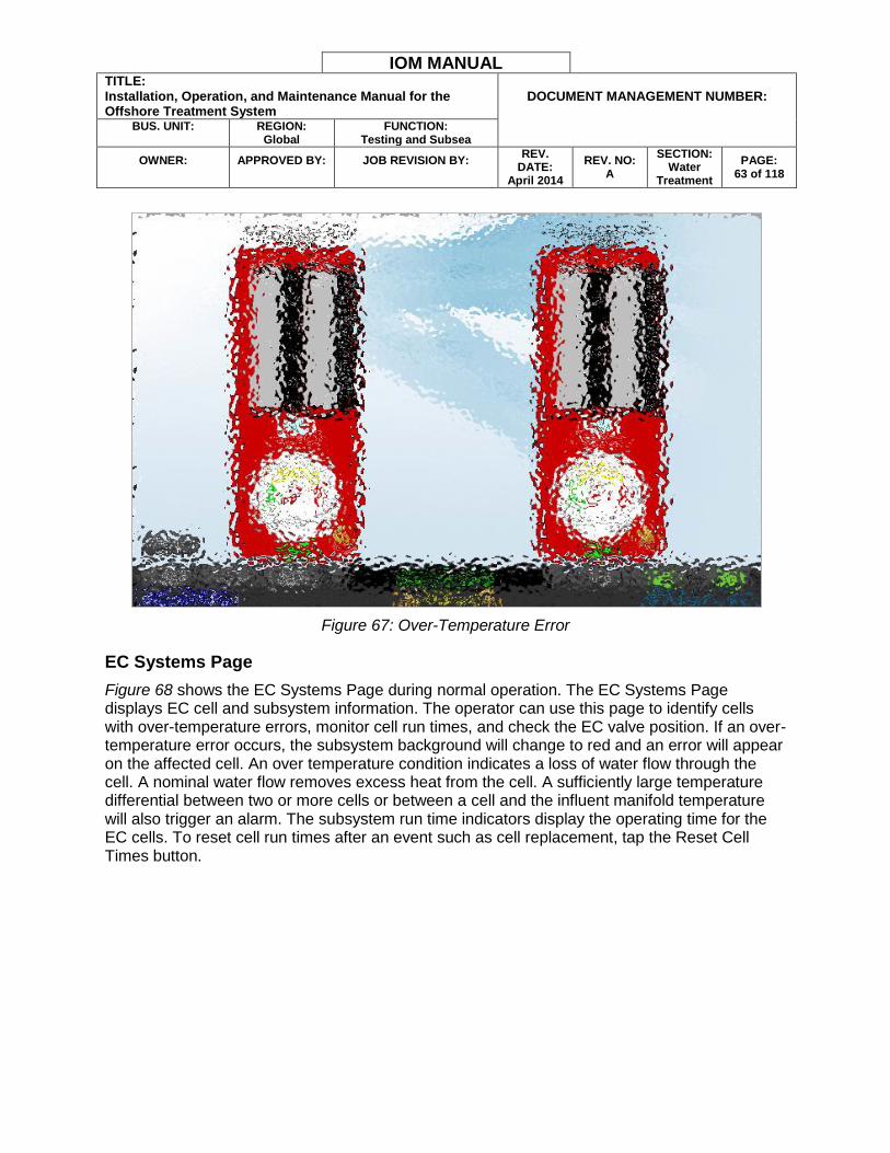
IOM MANUAL TITLE: Installation, Operation, and Maintenance Manual for the Offshore Treatment System
DOCUMENT MANAGEMENT NUMBER:
BUS. UNIT:
REGION:
Global FUNCTION:
Testing and Subsea
OWNER:
APPROVED BY:
JOB REVISION BY:
REV. DATE:
April 2014
REV. NO: A
SECTION: Water
Treatment
PAGE: 63 of 118
Figure 67: Over-Temperature Error
EC Systems Page
Figure 68 shows the EC Systems Page during normal operation. The EC Systems Page displays EC cell and subsystem information. The operator can use this page to identify cells with over-temperature errors, monitor cell run times, and check the EC valve position. If an over-temperature error occurs, the subsystem background will change to red and an error will appear on the affected cell. An over temperature condition indicates a loss of water flow through the cell. A nominal water flow removes excess heat from the cell. A sufficiently large temperature differential between two or more cells or between a cell and the influent manifold temperature will also trigger an alarm. The subsystem run time indicators display the operating time for the EC cells. To reset cell run times after an event such as cell replacement, tap the Reset Cell Times button.

IOM MANUAL TITLE: Installation, Operation, and Maintenance Manual for the Offshore Treatment System
DOCUMENT MANAGEMENT NUMBER:
BUS. UNIT:
REGION:
Global FUNCTION:
Testing and Subsea
OWNER:
APPROVED BY:
JOB REVISION BY:
REV. DATE:
April 2014
REV. NO: A
SECTION: Water
Treatment
PAGE: 64 of 118
Figure 68: EC Systems Page
IAF Page
Figure 69 shows the IAF Page. The IAF page displays status and flow information for IAF-related functions including:
Chemical injection pump call, IAF supply, sludge, and clearwell pump status.
REDACTED.
Valve positions.
Sludge valve timing and delay information.
REDACTED.
REDACTED.
Effluent OIW quality information.
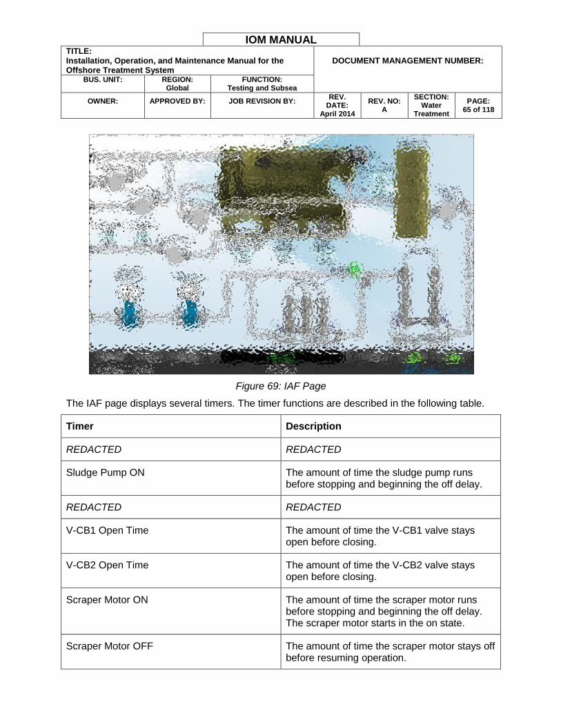
IOM MANUAL TITLE: Installation, Operation, and Maintenance Manual for the Offshore Treatment System
DOCUMENT MANAGEMENT NUMBER:
BUS. UNIT:
REGION:
Global FUNCTION:
Testing and Subsea
OWNER:
APPROVED BY:
JOB REVISION BY:
REV. DATE:
April 2014
REV. NO: A
SECTION: Water
Treatment
PAGE: 65 of 118
Figure 69: IAF Page
The IAF page displays several timers. The timer functions are described in the following table.
Timer Description
REDACTED REDACTED
Sludge Pump ON The amount of time the sludge pump runs before stopping and beginning the off delay.
REDACTED REDACTED
V-CB1 Open Time The amount of time the V-CB1 valve stays open before closing.
V-CB2 Open Time The amount of time the V-CB2 valve stays open before closing.
Scraper Motor ON The amount of time the scraper motor runs before stopping and beginning the off delay. The scraper motor starts in the on state.
Scraper Motor OFF The amount of time the scraper motor stays off before resuming operation.

IOM MANUAL TITLE: Installation, Operation, and Maintenance Manual for the Offshore Treatment System
DOCUMENT MANAGEMENT NUMBER:
BUS. UNIT:
REGION:
Global FUNCTION:
Testing and Subsea
OWNER:
APPROVED BY:
JOB REVISION BY:
REV. DATE:
April 2014
REV. NO: A
SECTION: Water
Treatment
PAGE: 68 of 118
Note: If the pH probe fails the calibration procedure or continues to give incorrect readings when using buffer solutions, it may need to be reset. Refer to the pH Probe Calibration section or the probe manufacturer’s documentation for more information.
pH Probe Calibration Reset
This section describes the periodic manual calibration procedure necessary to compensate for pH probe electrode aging. The Easy-Cal feature allows an operator to perform local calibration at the sensor. Refer to Figure 71 during the procedure.
Figure 71: pH Probe Signal Diagram
1. Disconnect the electrode from the sensor.
2. Reset the pH probe to factory calibration: Press and hold SW1 until LED (D1) illuminates steadily then turns off again. The light cycle should take approximately 10 seconds. Release SW1 when the LED turns off. The factory calibration reset is complete.
Note: The manufacturer recommends a factory calibration reset every time an electrode is replaced. It is not necessary to reset the probe with every initial installation or when performing periodic maintenance calibration.
3. Connect an electrode to the sensor.
WARNING: The electrode and sensor electrical interconnection must remain clean and dry at all times.
4. Place the electrode and sensor assembly into a calibration solution as follows:
Note: If the electrode is in good condition, then the pH probe will automatically recognize the buffer solution. The operator may use the buffer solutions in any order.
Use any two of the following international standard buffer solutions: pH 4.0, 7.0, or 10.0.
Completely submerge the electrode tip. Typically a 2.5 cm (1 in.) solution depth is sufficient for this purpose.
IOM MANUAL TITLE: Installation, Operation, and Maintenance Manual for the Offshore Treatment System
DOCUMENT MANAGEMENT NUMBER:
BUS. UNIT:
REGION:
Global FUNCTION:
Testing and Subsea
OWNER:
APPROVED BY:
JOB REVISION BY:
REV. DATE:
April 2014
REV. NO: A
SECTION: Water
Treatment
PAGE: 69 of 118
Note: Allow at least 30 seconds for the electrode response to stabilize before
continuing with the calibration procedure.
5. Press and hold SW1 for approximately 8 to 10 seconds. During this time LED (D1) will illuminate steadily then turn off.
6. Release SW1. If the LED blinks several times rapidly, the calibration was not successful. Inspect the sensor, electrode, all interconnections, and try the procedure again.
7. Remove the electrode and sensor assembly from the first buffer solution.
8. Rinse the electrode with clean water and place it in a second, different buffer solution. Allow at least 30 seconds for the electrode response to stabilize before continuing with the calibration procedure.
9. Press and hold SW1 for approximately 8 to 10 seconds. During this time LED (D1) will illuminate steadily then turn off.
10. Release SW1. If the LED blinks several times rapidly, the calibration was not successful. Inspect the sensor, electrode, all interconnections, and try the procedure again.
11. Calibration is complete. Reinstall the pH probe.

IOM MANUAL TITLE: Installation, Operation, and Maintenance Manual for the Offshore Treatment System
DOCUMENT MANAGEMENT NUMBER:
BUS. UNIT:
REGION:
Global FUNCTION:
Testing and Subsea
OWNER:
APPROVED BY:
JOB REVISION BY:
REV. DATE:
April 2014
REV. NO: A
SECTION: Water
Treatment
PAGE: 70 of 118
OIW Logging Page
Figure 72 shows the OIW Logging Page. The OIW Logging Page shows influent and effluent OIW data plotted as two separate lines over time. The left y-axis scale is in thousands of ppm to better represent the influent OIW data. The right y-axis scale is in tens of ppm to better represent the effluent OIW data. The page provides the option to start or stop OIW information logging by pressing the START LOGGING or STOP LOGGING buttons.
Figure 72: OIW Logging Page
IOM MANUAL TITLE: Installation, Operation, and Maintenance Manual for the Offshore Treatment System
DOCUMENT MANAGEMENT NUMBER:
BUS. UNIT:
REGION:
Global FUNCTION:
Testing and Subsea
OWNER:
APPROVED BY:
JOB REVISION BY:
REV. DATE:
April 2014
REV. NO: A
SECTION: Water
Treatment
PAGE: 71 of 118
pH Logging Page
Figure 73 shows the pH Logging Page. This page shows influent and effluent pH data plotted as two separate lines over time. The page provides the option to start or stop effluent pH information logging by pressing the START LOGGING or STOP LOGGING buttons.
Figure 73: pH Logging Page
Note: The START LOGGING and STOP LOGGING buttons on the OIW and pH Logging pages are linked together.
Logged Data Information
The logged OIW and pH data is stored in a .csv file on a USB flash drive plugged into the rear of the HMI. The USB flash drive must have the following folders present:
DataLog
REDACTED
REDACTED
Note: The folder names, including spelling and capitalization, must be exact. The folders must be created using a personal computer or laptop. There is no way to create the folders using the HMI.
Inside each log folder on the USB flash drive are three spreadsheet files. These files are created by the HMI the first time the START LOGGING button is pressed.
IOM MANUAL TITLE: Installation, Operation, and Maintenance Manual for the Offshore Treatment System
DOCUMENT MANAGEMENT NUMBER:
BUS. UNIT:
REGION:
Global FUNCTION:
Testing and Subsea
OWNER:
APPROVED BY:
JOB REVISION BY:
REV. DATE:
April 2014
REV. NO: A
SECTION: Water
Treatment
PAGE: 72 of 118
To retrieve the logged data complete the following steps:
1. Navigate to either the pH or OIW Logging Page.
2. Push the STOP LOGGING button.
3. Open the EC control cabinet door with the HMI mounted in it.
4. Remove the USB flash drive from the rear of the HMI.
5. (Optional) Insert a duplicate USB flash drive with the required folder structure and proceed directly to step 8 to minimize logged data loss.
6. Copy only the desired files to a laptop or other computer. Do not modify any folders.
7. Replace the USB flash drive.
8. Press the START LOGGING button. A message will appear stating that log initialization has ended. This indicates the HMI has started logging operations.
9. Close the EC control cabinet door.
Warning: Do NOT remove, alter, or copy the REDACTED files. These are reserved for PLC functions.
The following columns appear in the OIW log file in the OIWLog folder:
Column A – Time of day in milliseconds. Each day begins at midnight.
Columns B through E – PLC tag information. Operator may disregard.
Column F (Var1) – Influent OIW reading raw decimal value.
Column G (Var2) – Effluent OIW reading raw decimal value.
Column N – Sample date and time.
Column O – System condition when sample acquired. The values are treating or not treating. When the system is treating, the sample rate is every three minutes. When the system is not treating the sample rate is every hour.
Column P – HMI pathway name. Operator may disregard.
Note: The logged pH information is in the general DataLog folder. The logged alarm information is in the REDACTED folder. The column information is similar to the information provided for the OIW log file.
IOM MANUAL TITLE: Installation, Operation, and Maintenance Manual for the Offshore Treatment System
DOCUMENT MANAGEMENT NUMBER:
BUS. UNIT:
REGION:
Global FUNCTION:
Testing and Subsea
OWNER:
APPROVED BY:
JOB REVISION BY:
REV. DATE:
April 2014
REV. NO: A
SECTION: Water
Treatment
PAGE: 74 of 118
Alarm Page
Figure 75 shows the Alarm Page with an EC cell over-temperature alarm. The Alarm Page provides alarm details and interface options to acknowledge and clear alarms.
Figure 75: Alarm Page
The Alarm Page table displays the date, time, and a text description of the alarm condition. The Status column displays the alarm status. The Status column indications include the following states:
I – The alarm condition is input to the PLC. The alarm condition can be continuously occurring or input once. The alarm is not cleared, acknowledged, or reset.
IO – The alarm condition input to the PLC, and is now clear.
IA – The alarm condition input to the PLC, did not clear, but the operator acknowledged the alarm.
The Alarm Page features several icons for alarm information and management.
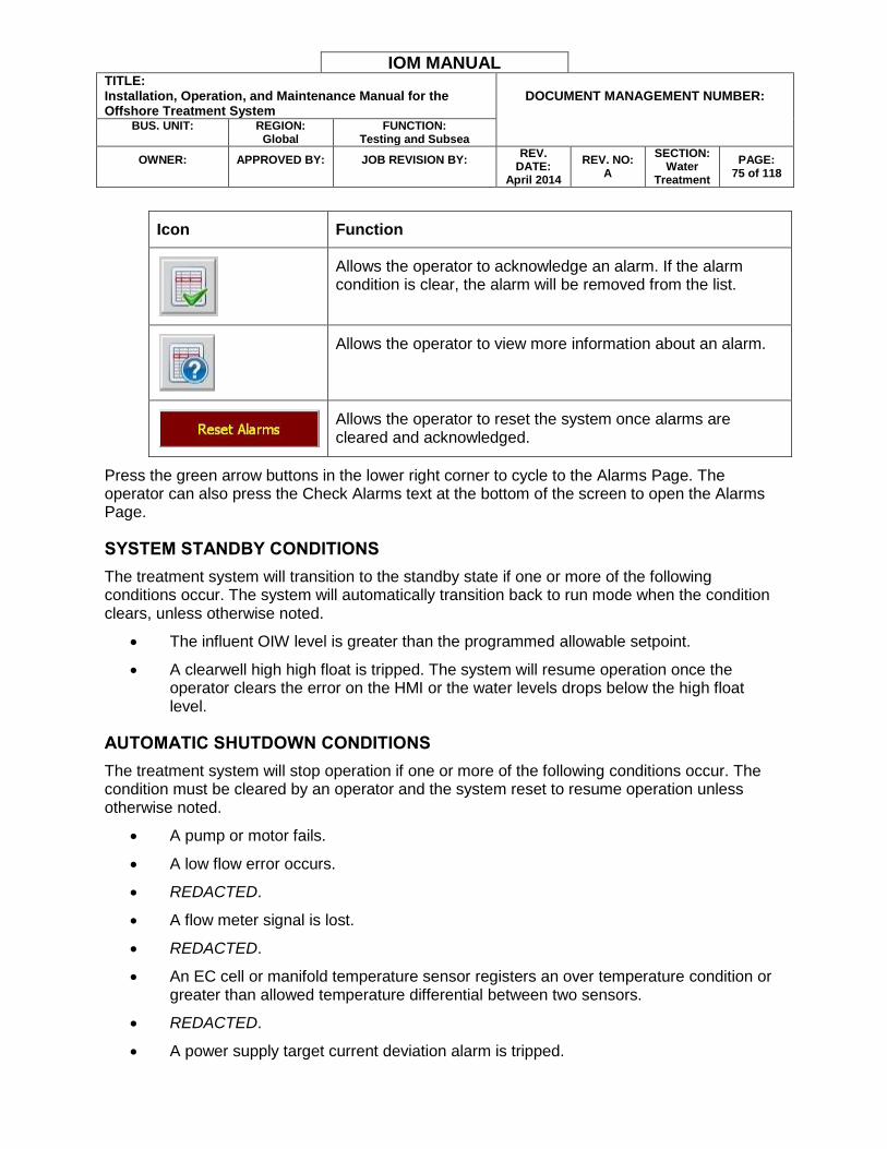
IOM MANUAL TITLE: Installation, Operation, and Maintenance Manual for the Offshore Treatment System
DOCUMENT MANAGEMENT NUMBER:
BUS. UNIT:
REGION:
Global FUNCTION:
Testing and Subsea
OWNER:
APPROVED BY:
JOB REVISION BY:
REV. DATE:
April 2014
REV. NO: A
SECTION: Water
Treatment
PAGE: 75 of 118
Icon Function
Allows the operator to acknowledge an alarm. If the alarm condition is clear, the alarm will be removed from the list.
Allows the operator to view more information about an alarm.
Allows the operator to reset the system once alarms are cleared and acknowledged.
Press the green arrow buttons in the lower right corner to cycle to the Alarms Page. The operator can also press the Check Alarms text at the bottom of the screen to open the Alarms Page.
SYSTEM STANDBY CONDITIONS
The treatment system will transition to the standby state if one or more of the following conditions occur. The system will automatically transition back to run mode when the condition clears, unless otherwise noted.
The influent OIW level is greater than the programmed allowable setpoint.
A clearwell high high float is tripped. The system will resume operation once the operator clears the error on the HMI or the water levels drops below the high float level.
AUTOMATIC SHUTDOWN CONDITIONS
The treatment system will stop operation if one or more of the following conditions occur. The condition must be cleared by an operator and the system reset to resume operation unless otherwise noted.
A pump or motor fails.
A low flow error occurs.
REDACTED.
A flow meter signal is lost.
REDACTED.
An EC cell or manifold temperature sensor registers an over temperature condition or greater than allowed temperature differential between two sensors.
REDACTED.
A power supply target current deviation alarm is tripped.
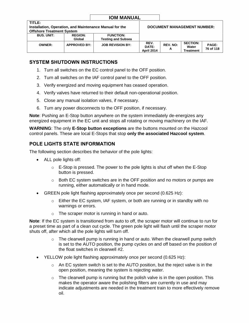
IOM MANUAL TITLE: Installation, Operation, and Maintenance Manual for the Offshore Treatment System
DOCUMENT MANAGEMENT NUMBER:
BUS. UNIT:
REGION:
Global FUNCTION:
Testing and Subsea
OWNER:
APPROVED BY:
JOB REVISION BY:
REV. DATE:
April 2014
REV. NO: A
SECTION: Water
Treatment
PAGE: 76 of 118
SYSTEM SHUTDOWN INSTRUCTIONS
1. Turn all switches on the EC control panel to the OFF position.
2. Turn all switches on the IAF control panel to the OFF position.
3. Verify energized and moving equipment has ceased operation.
4. Verify valves have returned to their default non-operational position.
5. Close any manual isolation valves, if necessary.
6. Turn any power disconnects to the OFF position, if necessary.
Note: Pushing an E-Stop button anywhere on the system immediately de-energizes any energized equipment in the EC unit and stops all rotating or moving machinery on the IAF.
WARNING: The only E-Stop button exceptions are the buttons mounted on the Hazcool control panels. These are local E-Stops that stop only the associated Hazcool system.
POLE LIGHTS STATE INFORMATION
The following section describes the behavior of the pole lights:
ALL pole lights off:
o E-Stop is pressed. The power to the pole lights is shut off when the E-Stop button is pressed.
o Both EC system switches are in the OFF position and no motors or pumps are running, either automatically or in hand mode.
GREEN pole light flashing approximately once per second (0.625 Hz):
o Either the EC system, IAF system, or both are running or in standby with no warnings or errors.
o The scraper motor is running in hand or auto.
Note: If the EC system is transitioned from auto to off, the scraper motor will continue to run for a preset time as part of a clean out cycle. The green pole light will flash until the scraper motor shuts off, after which all the pole lights will turn off.
o The clearwell pump is running in hand or auto. When the clearwell pump switch is set to the AUTO position, the pump cycles on and off based on the position of the float switches in clearwell #2.
YELLOW pole light flashing approximately once per second (0.625 Hz):
o An EC system switch is set to the AUTO position, but the reject valve is in the open position, meaning the system is rejecting water.
o The clearwell pump is running but the polish valve is in the open position. This makes the operator aware the polishing filters are currently in use and may indicate adjustments are needed in the treatment train to more effectively remove oil.
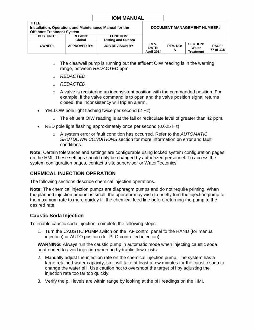
IOM MANUAL TITLE: Installation, Operation, and Maintenance Manual for the Offshore Treatment System
DOCUMENT MANAGEMENT NUMBER:
BUS. UNIT:
REGION:
Global FUNCTION:
Testing and Subsea
OWNER:
APPROVED BY:
JOB REVISION BY:
REV. DATE:
April 2014
REV. NO: A
SECTION: Water
Treatment
PAGE: 77 of 118
o The clearwell pump is running but the effluent OIW reading is in the warning
range, between REDACTED ppm.
o REDACTED.
o REDACTED.
o A valve is registering an inconsistent position with the commanded position. For example, if the valve command is to open and the valve position signal returns closed, the inconsistency will trip an alarm.
YELLOW pole light flashing twice per second (2 Hz)
o The effluent OIW reading is at the fail or recirculate level of greater than 42 ppm.
RED pole light flashing approximately once per second (0.625 Hz):
o A system error or fault condition has occurred. Refer to the AUTOMATIC SHUTDOWN CONDITIONS section for more information on error and fault conditions.
Note: Certain tolerances and settings are configurable using locked system configuration pages on the HMI. These settings should only be changed by authorized personnel. To access the system configuration pages, contact a site supervisor or WaterTectonics.
CHEMICAL INJECTION OPERATION
The following sections describe chemical injection operations.
Note: The chemical injection pumps are diaphragm pumps and do not require priming. When the planned injection amount is small, the operator may wish to briefly turn the injection pump to the maximum rate to more quickly fill the chemical feed line before returning the pump to the desired rate.
Caustic Soda Injection
To enable caustic soda injection, complete the following steps:
1. Turn the CAUSTIC PUMP switch on the IAF control panel to the HAND (for manual injection) or AUTO position (for PLC-controlled injection).
WARNING: Always run the caustic pump in automatic mode when injecting caustic soda unattended to avoid injection when no hydraulic flow exists.
2. Manually adjust the injection rate on the chemical injection pump. The system has a large retained water capacity, so it will take at least a few minutes for the caustic soda to change the water pH. Use caution not to overshoot the target pH by adjusting the injection rate too far too quickly.
3. Verify the pH levels are within range by looking at the pH readings on the HMI.
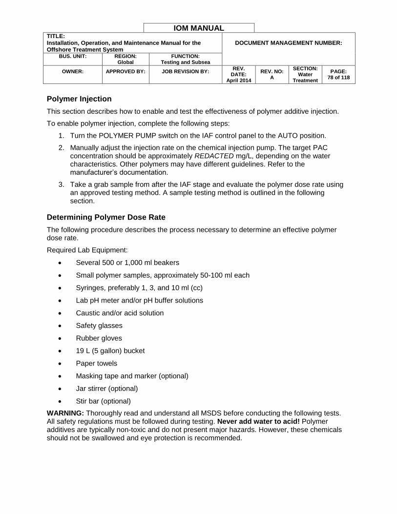
IOM MANUAL TITLE: Installation, Operation, and Maintenance Manual for the Offshore Treatment System
DOCUMENT MANAGEMENT NUMBER:
BUS. UNIT:
REGION:
Global FUNCTION:
Testing and Subsea
OWNER:
APPROVED BY:
JOB REVISION BY:
REV. DATE:
April 2014
REV. NO: A
SECTION: Water
Treatment
PAGE: 78 of 118
Polymer Injection
This section describes how to enable and test the effectiveness of polymer additive injection.
To enable polymer injection, complete the following steps:
1. Turn the POLYMER PUMP switch on the IAF control panel to the AUTO position.
2. Manually adjust the injection rate on the chemical injection pump. The target PAC concentration should be approximately REDACTED mg/L, depending on the water characteristics. Other polymers may have different guidelines. Refer to the manufacturer’s documentation.
3. Take a grab sample from after the IAF stage and evaluate the polymer dose rate using an approved testing method. A sample testing method is outlined in the following section.
Determining Polymer Dose Rate
The following procedure describes the process necessary to determine an effective polymer dose rate.
Required Lab Equipment:
Several 500 or 1,000 ml beakers
Small polymer samples, approximately 50-100 ml each
Syringes, preferably 1, 3, and 10 ml (cc)
Lab pH meter and/or pH buffer solutions
Caustic and/or acid solution
Safety glasses
Rubber gloves
19 L (5 gallon) bucket
Paper towels
Masking tape and marker (optional)
Jar stirrer (optional)
Stir bar (optional)
WARNING: Thoroughly read and understand all MSDS before conducting the following tests. All safety regulations must be followed during testing. Never add water to acid! Polymer additives are typically non-toxic and do not present major hazards. However, these chemicals should not be swallowed and eye protection is recommended.

IOM MANUAL TITLE: Installation, Operation, and Maintenance Manual for the Offshore Treatment System
DOCUMENT MANAGEMENT NUMBER:
BUS. UNIT:
REGION:
Global FUNCTION:
Testing and Subsea
OWNER:
APPROVED BY:
JOB REVISION BY:
REV. DATE:
April 2014
REV. NO: A
SECTION: Water
Treatment
PAGE: 79 of 118
SAMPLE PREPARATION:
1. Fill a 19 L (5 gallon) pail to the halfway point with a representative sample of the test wastewater. Ideally, take this sample after any prescreen equipment, but before coagulant or flocculant injection.
2. Check the wastewater pH.
3. Adjust the wastewater pH to the desired level, if necessary. For typical oil wastewater being treated with aluminum ions the desired pH is approximately 5–7. Add caustic soda to increase the pH or acid to decrease the wastewater pH.
Note: Ensure the wastewater sample is thoroughly mixed and the pH carefully monitored during this adjustment. If the desired pH range is passed, obtain a new sample and readjust accordingly.
FLOCCULATION TEST
1. Obtain 1 L source sample water for testing.
2. Add 1 drop of polymer additive.
3. Shake sample vigorously. Let sample stand for several minutes.
4. Repeat steps 2 and 3 until flocculation occurs and the test achieves the desired result. Note the number of drops used.
5. In a liter each drop of polymer is equal to a 50 ppm (50 mg/L) product concentration. The number of drops in a 1 L test serves as a basis for full-scale treatment calculations.
FULL SCALE CALCULATIONS:
The treatment system chemical injection pumps include one adjustment knob that controls flow as a percentage of total rated flow. The following calculations allow an operator to scale small test results to determine the target chemical injection pump rate.
Determine the target chemical flow in liters per hour (L/hr):
𝐹𝑙𝑜𝑤L
min× 𝐷𝑜𝑠𝑒
mg
L×
1 L
𝑆𝑝𝑒𝑐. 𝐺𝑟𝑎𝑣. (mg)×
1
𝐶𝑜𝑛𝑐. (%)× 𝑇𝑖𝑚𝑒
60 min
1 hr= 𝐶ℎ𝑒𝑚𝑖𝑐𝑎𝑙 𝐹𝑙𝑜𝑤
L
hr
Determine the target pump rate based on the target chemical flow and the pump maximum flow rating:
𝐶ℎ𝑒𝑚𝑖𝑐𝑎𝑙 𝐹𝑙𝑜𝑤 ( L hr⁄ )
100% 𝐶ℎ𝑒𝑚𝑖𝑐𝑎𝑙 𝑃𝑢𝑚𝑝 𝐹𝑙𝑜𝑤 𝑅𝑎𝑡𝑖𝑛𝑔 (L hr⁄ )= 𝑇𝑎𝑟𝑔𝑒𝑡 𝑃𝑢𝑚𝑝 𝑅𝑎𝑡𝑒 (%)
Note: The chemical injection pumps on the treatment system are rated for REDACTED L/hr at 100% flow rate.
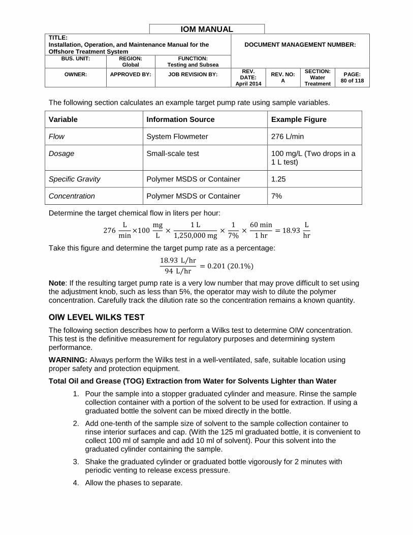
IOM MANUAL TITLE: Installation, Operation, and Maintenance Manual for the Offshore Treatment System
DOCUMENT MANAGEMENT NUMBER:
BUS. UNIT:
REGION:
Global FUNCTION:
Testing and Subsea
OWNER:
APPROVED BY:
JOB REVISION BY:
REV. DATE:
April 2014
REV. NO: A
SECTION: Water
Treatment
PAGE: 80 of 118
The following section calculates an example target pump rate using sample variables.
Variable Information Source Example Figure
Flow System Flowmeter 276 L/min
Dosage Small-scale test 100 mg/L (Two drops in a 1 L test)
Specific Gravity Polymer MSDS or Container 1.25
Concentration Polymer MSDS or Container 7%
Determine the target chemical flow in liters per hour:
276 L
min×100
mg
L ×
1 L
1,250,000 mg ×
1
7% ×
60 min
1 hr = 18.93
L
hr
Take this figure and determine the target pump rate as a percentage:
18.93 L hr⁄
94 L hr⁄ = 0.201 (20.1%)
Note: If the resulting target pump rate is a very low number that may prove difficult to set using the adjustment knob, such as less than 5%, the operator may wish to dilute the polymer concentration. Carefully track the dilution rate so the concentration remains a known quantity.
OIW LEVEL WILKS TEST
The following section describes how to perform a Wilks test to determine OIW concentration. This test is the definitive measurement for regulatory purposes and determining system performance.
WARNING: Always perform the Wilks test in a well-ventilated, safe, suitable location using proper safety and protection equipment.
Total Oil and Grease (TOG) Extraction from Water for Solvents Lighter than Water
1. Pour the sample into a stopper graduated cylinder and measure. Rinse the sample collection container with a portion of the solvent to be used for extraction. If using a graduated bottle the solvent can be mixed directly in the bottle.
2. Add one-tenth of the sample size of solvent to the sample collection container to rinse interior surfaces and cap. (With the 125 ml graduated bottle, it is convenient to collect 100 ml of sample and add 10 ml of solvent). Pour this solvent into the graduated cylinder containing the sample.
3. Shake the graduated cylinder or graduated bottle vigorously for 2 minutes with periodic venting to release excess pressure.
4. Allow the phases to separate.
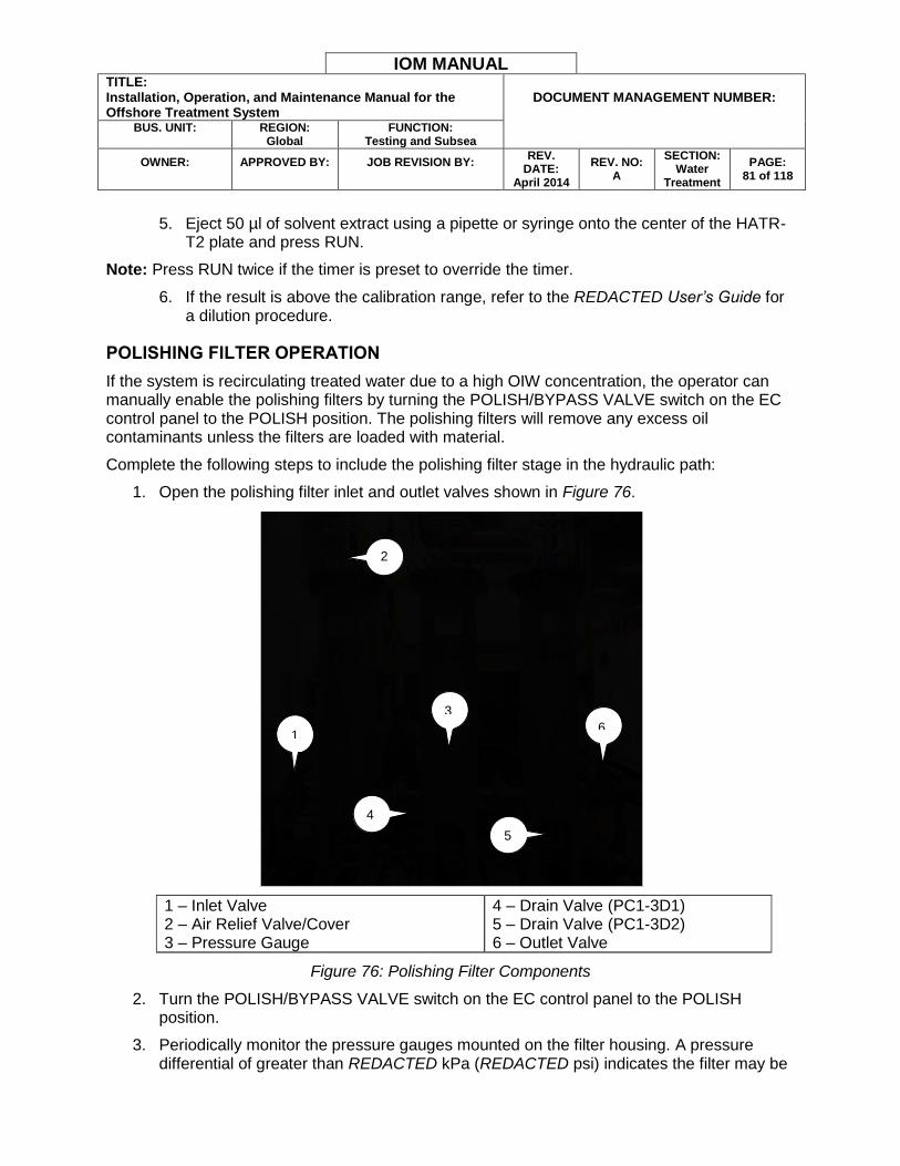
IOM MANUAL TITLE: Installation, Operation, and Maintenance Manual for the Offshore Treatment System
DOCUMENT MANAGEMENT NUMBER:
BUS. UNIT:
REGION:
Global FUNCTION:
Testing and Subsea
OWNER:
APPROVED BY:
JOB REVISION BY:
REV. DATE:
April 2014
REV. NO: A
SECTION: Water
Treatment
PAGE: 81 of 118
5. Eject 50 µl of solvent extract using a pipette or syringe onto the center of the HATR-
T2 plate and press RUN.
Note: Press RUN twice if the timer is preset to override the timer.
6. If the result is above the calibration range, refer to the REDACTED User’s Guide for a dilution procedure.
POLISHING FILTER OPERATION
If the system is recirculating treated water due to a high OIW concentration, the operator can manually enable the polishing filters by turning the POLISH/BYPASS VALVE switch on the EC control panel to the POLISH position. The polishing filters will remove any excess oil contaminants unless the filters are loaded with material.
Complete the following steps to include the polishing filter stage in the hydraulic path:
1. Open the polishing filter inlet and outlet valves shown in Figure 76.
1 – Inlet Valve 2 – Air Relief Valve/Cover 3 – Pressure Gauge
4 – Drain Valve (PC1-3D1) 5 – Drain Valve (PC1-3D2) 6 – Outlet Valve
Figure 76: Polishing Filter Components
2. Turn the POLISH/BYPASS VALVE switch on the EC control panel to the POLISH position.
3. Periodically monitor the pressure gauges mounted on the filter housing. A pressure differential of greater than REDACTED kPa (REDACTED psi) indicates the filter may be
1 6
3
2
5
4
IOM MANUAL TITLE: Installation, Operation, and Maintenance Manual for the Offshore Treatment System
DOCUMENT MANAGEMENT NUMBER:
BUS. UNIT:
REGION:
Global FUNCTION:
Testing and Subsea
OWNER:
APPROVED BY:
JOB REVISION BY:
REV. DATE:
April 2014
REV. NO: A
SECTION: Water
Treatment
PAGE: 82 of 118
mechanically fouled and requires replacement. Polishing filter replacement is similar to the steps described in the BAG FILTER REPLACEMENT section.
Note: The polishing filters are infused with a special compound to remove hydrocarbons. Each filter is rated to remove only a certain amount of contaminant. Even if the pressure gauges show approximately the same pressure, the filter may still be consumed. Monitor both the effluent OIW level and the filter pressures to ensure discharge compliance and filter effectiveness.
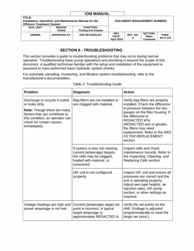
IOM MANUAL TITLE: Installation, Operation, and Maintenance Manual for the Offshore Treatment System
DOCUMENT MANAGEMENT NUMBER:
BUS. UNIT:
REGION:
Global FUNCTION:
Testing and Subsea
OWNER:
APPROVED BY:
JOB REVISION BY:
REV. DATE:
April 2014
REV. NO: A
SECTION: Water
Treatment
PAGE: 83 of 118
SECTION 6 - TROUBLESHOOTING
This section provides a guide to troubleshooting problems that may occur during normal operation. Troubleshooting basic pump operations and plumbing is beyond the scope of this document. A qualified technician familiar with the setup and installation of the equipment is assumed to have performed basic hydraulic system checks.
For automatic sampling, monitoring, and filtration system troubleshooting, refer to the manufacturer’s documentation.
Table 2: Troubleshooting Guide
Problem Diagnosis Action
Discharge or recycle is turbid or looks dirty.
Note: Though there are many factors that can contribute to this condition, an operator can check for certain causes immediately.
Bag filters are not installed or are clogged with material.
Verify bag filters are properly installed. Check the difference in pressure between the two gauges on the filter housing. If the difference is REDACTED kPa (REDACTED psi) or greater, the filters may need replacement. Refer to the BAG FILTER REPLACEMENT section.
If system is also not meeting current (amperage) targets, the cells may be clogged, loaded with material, or consumed.
Inspect cells and check maintenance records. Refer to the Inspecting, Cleaning, and Replacing Cells section.
IAF unit is not configured properly.
Inspect IAF unit and ensure all pressures are correct and the unit is operating properly. Adjust weir pipe heights, air injection rates, IAF pump suction, or other settings as required.
Voltage readings are high and preset amperage is not met.
Current (amperage) target set point is incorrect. A typical target amperage is approximately REDACTED A.
Verify the set points on the HMI. (Voltage is adjusted programmatically to meet the target set point.)
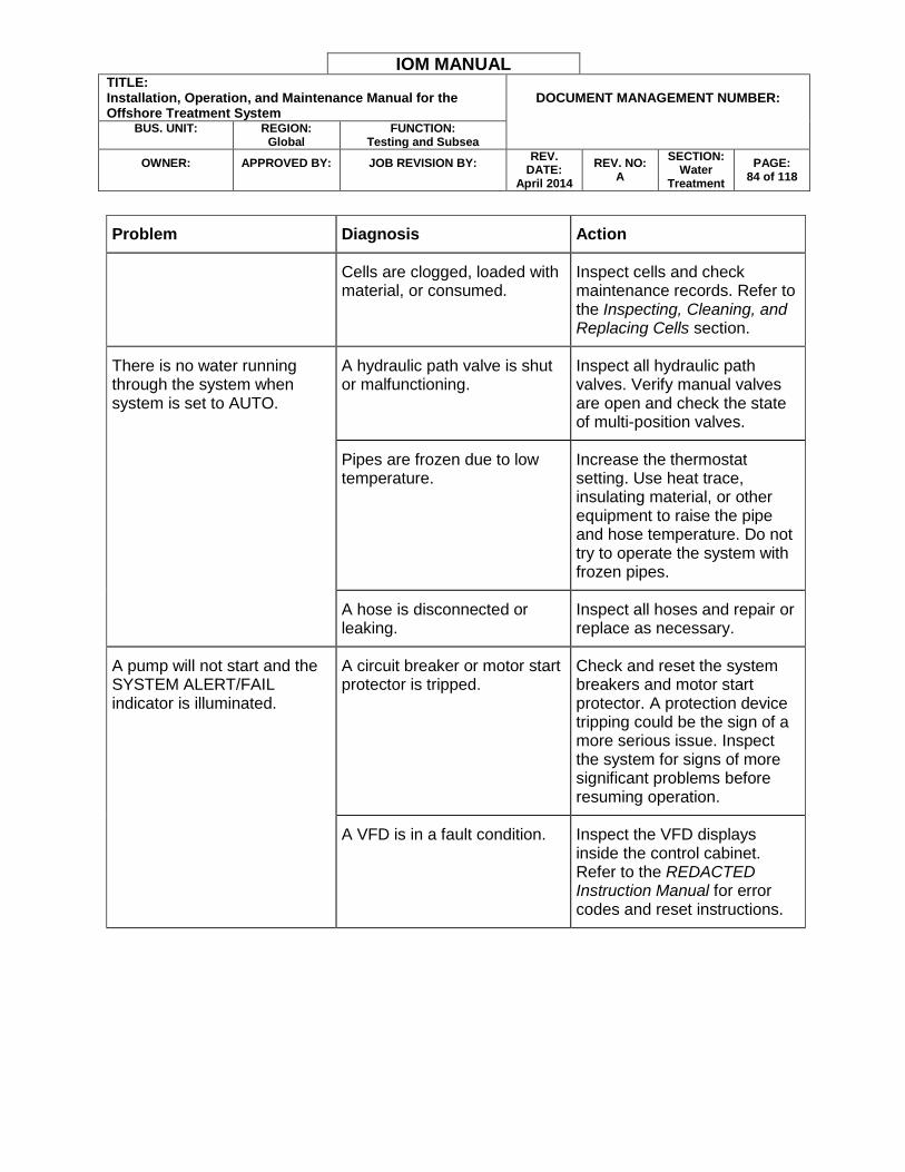
IOM MANUAL TITLE: Installation, Operation, and Maintenance Manual for the Offshore Treatment System
DOCUMENT MANAGEMENT NUMBER:
BUS. UNIT:
REGION:
Global FUNCTION:
Testing and Subsea
OWNER:
APPROVED BY:
JOB REVISION BY:
REV. DATE:
April 2014
REV. NO: A
SECTION: Water
Treatment
PAGE: 84 of 118
Problem Diagnosis Action
Cells are clogged, loaded with material, or consumed.
Inspect cells and check maintenance records. Refer to the Inspecting, Cleaning, and Replacing Cells section.
There is no water running through the system when system is set to AUTO.
A hydraulic path valve is shut or malfunctioning.
Inspect all hydraulic path valves. Verify manual valves are open and check the state of multi-position valves.
Pipes are frozen due to low temperature.
Increase the thermostat setting. Use heat trace, insulating material, or other equipment to raise the pipe and hose temperature. Do not try to operate the system with frozen pipes.
A hose is disconnected or leaking.
Inspect all hoses and repair or replace as necessary.
A pump will not start and the SYSTEM ALERT/FAIL indicator is illuminated.
A circuit breaker or motor start protector is tripped.
Check and reset the system breakers and motor start protector. A protection device tripping could be the sign of a more serious issue. Inspect the system for signs of more significant problems before resuming operation.
A VFD is in a fault condition. Inspect the VFD displays inside the control cabinet. Refer to the REDACTED Instruction Manual for error codes and reset instructions.
IOM MANUAL TITLE: Installation, Operation, and Maintenance Manual for the Offshore Treatment System
DOCUMENT MANAGEMENT NUMBER:
BUS. UNIT:
REGION:
Global FUNCTION:
Testing and Subsea
OWNER:
APPROVED BY:
JOB REVISION BY:
REV. DATE:
April 2014
REV. NO: A
SECTION: Water
Treatment
PAGE: 85 of 118
SECTION 7 - MAINTENANCE
To ensure treatment system performance and longevity, please adhere to the following maintenance guidelines.
SHORT-TERM STANDBY PERIODS
Complete the following steps to secure the treatment system for short periods of downtime.
1. If the system is going to be non-operational for greater than 24 hours, flush the system with water to remove oil, solids, and other contaminants from the system.
Note: The operator may leave any volume of water in the IAF flotation chamber that does not overflow the chamber. Storing dirty water may leave a residue in the IAF unit that could harden and become difficult to remove.
2. Turn the system off.
3. Close any manual isolation valves, if required.
4. Turn any power disconnect switches to the OFF position and secure the system against unauthorized activation.
LONG-TERM STORAGE
When storing the system for long periods of time, complete the following steps.
1. Flush the system with water to remove oil, solids, and other contaminants from the system.
2. Disconnect any supply hoses between chemical sources and the chemical injection pumps.
3. Flush the chemical injection pumps with water.
4. Drain the system by following the instructions in the SYSTEM DRAIN AND BLOWOUT PROCEDURE section.
5. Wash the IAF treatment surfaces before any residue hardens.
6. Remove the pH probes and place the protective caps over the ends.
7. Protect the IAF plastic components from very long term (greater than 60 day) sun exposure with a cover such as a tarp.
8. Turn all power disconnects to the OFF position.
9. If disconnecting the system, roll and store all cables and hoses in their appropriate storage locations.
IOM MANUAL TITLE: Installation, Operation, and Maintenance Manual for the Offshore Treatment System
DOCUMENT MANAGEMENT NUMBER:
BUS. UNIT:
REGION:
Global FUNCTION:
Testing and Subsea
OWNER:
APPROVED BY:
JOB REVISION BY:
REV. DATE:
April 2014
REV. NO: A
SECTION: Water
Treatment
PAGE: 86 of 118
SYSTEM DRAIN AND BLOWOUT PROCEDURE
Warning: Install blowout ports before beginning the blowout procedure to minimize the risk of spilling any liquid. Install one port after the external supply pump (before EC influent) and one after the polishing filter effluent check valve (IAF EFFLUENT).
1. Turn the EC SYSTEM 1, EC SYSTEM 2, and all pump and motor switches to the OFF position.
2. Put the EC/REJECT valve (V-EC/RJCT) in the EC position.
3. Open the cell drain valves (V-10, V-12, V-14, V-16) and plug in the cell drain pump (P-01). Allow the pump to run until the pump begins to draw air and the flow of water stops.
4. Put the EC/REJECT valve in the REJECT position. Pressurize the influent supply hose to blow any residual liquid into the source or rejection tank.
5. Put the DISCHARGE/RECIRC valve (V-D/R) in the discharge position.
6. Blow out the IAF influent line by pressurizing the line after the polish filter effluent check valve. This blows any residual liquid through the EC unit and out the discharge line. Disconnect the IAF influent line and use it to drain the top two-thirds of the polishing filter housings.
7. Close the FLOCCULATOR ISOLATION valve (V-48) and drain any residual liquid through the EC effluent sample port (V-24). Remove the cam hose from the EC unit and drain the hose.
8. Open the flocculator isolation valve and drain any residual liquid from the flocculator.
a. If the system is not installed in the stacked configuration, the cell drain pump will drain most of the flocculator as long as the flocculator isolation valve is open.
9. Open both cone bottom valves (V-CB1 and V-CB2) to drain the sludge tank and IAF flotation chamber through the sludge pump (P-SLDGE).
10. Open the clearwell #1 drain valve (V-51) to drain clearwell #1.
11. The operator can drain clearwell #2 through the 10 cm (4 in.) gravity-fed effluent line beneath the IAF system or by opening the clearwell #2 drain valve (V-37).
12. Use the IAF DRAIN VALVE (V-52) to drain the IAF air/water compartment.
13. Drain the bag and polishing filters by opening all the 1.3 cm (0.5 in.) drain ball valves beneath the filter housings. Open the ball valves on top of the filter housings to provide an air inlet to accelerate the housing drain.
14. Clean up any spills, if required.
BAG FILTER REPLACEMENT
Bag filters typically require replacement when the difference between the pressures shown on the two gauges is REDACTED kPa (REDACTED psi) or greater. If the difference between the pressures is REDACTED kPa (REDACTED psi) or greater, replace or remove the bag filter as

IOM MANUAL TITLE: Installation, Operation, and Maintenance Manual for the Offshore Treatment System
DOCUMENT MANAGEMENT NUMBER:
BUS. UNIT:
REGION:
Global FUNCTION:
Testing and Subsea
OWNER:
APPROVED BY:
JOB REVISION BY:
REV. DATE:
April 2014
REV. NO: A
SECTION: Water
Treatment
PAGE: 87 of 118
soon as possible as the pressure may crush and distort the filter. If the filter is crushed it will not effectively remove particulates. Complete the following steps to replace a bag filter:
1. Turn off the treatment system by setting the control panel system switches to the OFF position.
2. Close the upstream inlet valve, shown with other components in Figure 77.
3. Open the air vent to relieve any residual air pressure trapped in the filter housing and create an air inlet to help the housing drain faster.
4. Allow the filter housings to drain as much as possible, then close the downstream outlet valve.
1 – Inlet Valve 2 – Housing Cover 3 – Swing Bolt
4 – Air Vent 5 – Outlet Valve
Figure 77: Bag Filter Components
5. Unscrew the swing bolts and lower them onto the filter housing.
6. Remove the filter housing cover.
1
2
4
5
3
IOM MANUAL TITLE: Installation, Operation, and Maintenance Manual for the Offshore Treatment System
DOCUMENT MANAGEMENT NUMBER:
BUS. UNIT:
REGION:
Global FUNCTION:
Testing and Subsea
OWNER:
APPROVED BY:
JOB REVISION BY:
REV. DATE:
April 2014
REV. NO: A
SECTION: Water
Treatment
PAGE: 88 of 118
7. Remove the used filter bag by grasping the loop on the bag and lifting the bag upward.
Discard the used filter bag.
8. Remove the support basket from the filter housing. Clean and inspect the basket for any damage.
9. Clean and inspect the filter housing interior and components. Inspect the o-ring groove and o-ring for damage.
10. Reinstall the support basket.
11. Insert a new filter bag. Ensure the new filter bag is spread out inside the support basket.
12. Reinstall the filter housing cover.
13. Close the air vent.
14. Reopen the inlet and outlet valves.
15. Restart the treatment system.
Note: One bag filter can remain in service while the other is being replaced. Refer to the REDACTED Series Installation and Operation Manual for more information on the bag filters.
EC MAINTENANCE
This section describes EC stage maintenance procedures.
Inspecting, Cleaning, and Replacing Cells
To remove an EC cell for inspection, cleaning, or replacement, complete the following steps:
1. Check the EC cells and surrounding area for indications of problems such as leaks or loose interconnect power cables.
2. Power off the EC system using the appropriate EC SYSTEM 1–2 switch on the control cabinet. Open the EC 1 and EC 2 breakers for safety purposes.
3. Close the EC cell isolation valves and open the cell housing drain valve near the floor. Turn on the drain pump to drain the cell.
4. Loosen and remove the flange bolts.
DANGER: Do not disconnect or reconnect any cell leads while the EC system is operating. Do not operate the system without the cell leads connected and the cells filled with water.
5. Remove the power cables from the top of the cell. Turn the cable until it removes easily.
6. Remove the cell vent valve at the top of the cell. Grasp the slide ring and pull downwards while gently pulling upwards on the vent.
7. Remove the EC cell. Residual water may spill from the cell plates. Use caution when removing the cell to avoid plumbing damage.
IOM MANUAL TITLE: Installation, Operation, and Maintenance Manual for the Offshore Treatment System
DOCUMENT MANAGEMENT NUMBER:
BUS. UNIT:
REGION:
Global FUNCTION:
Testing and Subsea
OWNER:
APPROVED BY:
JOB REVISION BY:
REV. DATE:
April 2014
REV. NO: A
SECTION: Water
Treatment
PAGE: 89 of 118
8. Inspect the cell plates for sediment build up and thickness. If the cell looks dirty but the
plates are substantial, clean the cell with a pressure washer. Replace the cell by completing the remaining steps. If the cell appears consumed it must be replaced.
9. Place the old cell in a waterproof container to avoid spillage.
10. Save the rubber flange gasket and put the gasket back in place to receive the new or cleaned EC cell.
11. Install the new or cleaned EC cell by placing a new cell in the old cell location or returning a cleaned cell to the EC cell subsystem.
12. Install the flange bolts with the following precautions:
Tighten the bolts in the following order: 1 and 5, 4 and 8, 2 and 6, 3 and 7.
Use no more than REDACTED Nm (REDACTED lb-ft) of torque on each bolt.
13. Reattach the cell power cables. Ensure the cables are secure by pushing down and turning the connector until the connection is tight.
14. Reattach the cell vent valve.
15. Turn off cell drain pump
16. Close cell housing drains.
17. Open EC cell isolation valves.
IAF MAINTENANCE
The following sections describe the IAF unit maintenance schedule.
Routine Startup Maintenance
During the first 50 hours of operation, or after a prolonged period of inactivity, complete the following maintenance operations:
Check the IAF pump for proper operation.
Check the IAF pump for proper alignment. Refer to the IAF Pump Alignment section for more information.
Check all piping for leaks.
Check the top skimmer assembly for proper chain tension. Refer to Figure 81 for a representation of a properly tightened chain.
Monthly Maintenance
Complete the following maintenance operations once a month or as needed:
Drain the IAF unit. Rinse out the IAF unit with a medium pressure water stream.
Check the top chain and flight skimmer assembly for proper chain tension.

IOM MANUAL TITLE: Installation, Operation, and Maintenance Manual for the Offshore Treatment System
DOCUMENT MANAGEMENT NUMBER:
BUS. UNIT:
REGION:
Global FUNCTION:
Testing and Subsea
OWNER:
APPROVED BY:
JOB REVISION BY:
REV. DATE:
April 2014
REV. NO: A
SECTION: Water
Treatment
PAGE: 90 of 118
Quarterly Maintenance
Complete the following maintenance operations on an as-needed or quarterly basis:
Lubricate the take-up frame bearings and four bolt flange bearing on the top of the skimmer assembly.
Lubricate the top sludge rake bearings and drive motor.
Inspect the ultra high molecular weight (UHMW) wear blocks on the skimmer assembly.
Check the IAF pump for proper alignment. Lubricate the motor if necessary.
Lubricate other moving parts if necessary.
IAF Pump Alignment
The IAF pump must be periodically checked for proper alignment. To check the pump couplings for proper alignment, complete the following steps:
1. Stop the IAF unit by pressing the E-Stop button.
2. Disable all power to the IAF unit by turning the power disconnect on the IAF control panel to the OFF position. Complete any required lockout/tagout procedures.
3. Remove the protective housing from the pump couplings. The housing is located adjacent to the pump motor. The exposed pump couplings are shown in Figure 78.
Figure 78: IAF Pump Couplers
4. Check the top and sides of the pump couplings for a square and even orientation with each other. The couplings should be as close to parallel as possible.
Note: The pump couplings are floating. The length each coupling extends from the pump or motor is less critical than coupling alignment.
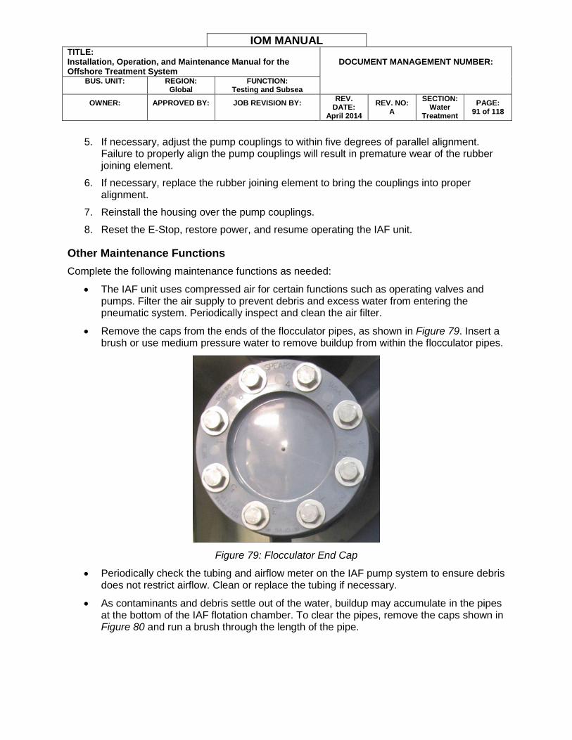
IOM MANUAL TITLE: Installation, Operation, and Maintenance Manual for the Offshore Treatment System
DOCUMENT MANAGEMENT NUMBER:
BUS. UNIT:
REGION:
Global FUNCTION:
Testing and Subsea
OWNER:
APPROVED BY:
JOB REVISION BY:
REV. DATE:
April 2014
REV. NO: A
SECTION: Water
Treatment
PAGE: 91 of 118
5. If necessary, adjust the pump couplings to within five degrees of parallel alignment.
Failure to properly align the pump couplings will result in premature wear of the rubber joining element.
6. If necessary, replace the rubber joining element to bring the couplings into proper alignment.
7. Reinstall the housing over the pump couplings.
8. Reset the E-Stop, restore power, and resume operating the IAF unit.
Other Maintenance Functions
Complete the following maintenance functions as needed:
The IAF unit uses compressed air for certain functions such as operating valves and pumps. Filter the air supply to prevent debris and excess water from entering the pneumatic system. Periodically inspect and clean the air filter.
Remove the caps from the ends of the flocculator pipes, as shown in Figure 79. Insert a brush or use medium pressure water to remove buildup from within the flocculator pipes.
Figure 79: Flocculator End Cap
Periodically check the tubing and airflow meter on the IAF pump system to ensure debris does not restrict airflow. Clean or replace the tubing if necessary.
As contaminants and debris settle out of the water, buildup may accumulate in the pipes at the bottom of the IAF flotation chamber. To clear the pipes, remove the caps shown in Figure 80 and run a brush through the length of the pipe.

IOM MANUAL TITLE: Installation, Operation, and Maintenance Manual for the Offshore Treatment System
DOCUMENT MANAGEMENT NUMBER:
BUS. UNIT:
REGION:
Global FUNCTION:
Testing and Subsea
OWNER:
APPROVED BY:
JOB REVISION BY:
REV. DATE:
April 2014
REV. NO: A
SECTION: Water
Treatment
PAGE: 97 of 118
SECTION 8 - SPECIFICATIONS
This section describes the treatment system specifications.
System Dimensions and Weight
EC Unit
Dimensions: REDACTED m (REDACTED ft.) (LxWxH)
Weight: REDACTED kg (REDACTED lbs.) (sling included)
IAF Unit
Dimensions: REDACTED m (REDACTED ft.) (LxWxH)
Weight: REDACTED kg (REDACTED lbs.) (sling included)
Lifting Slings in Shipping Crates
Crate Dimensions: REDACTED m (REDACTED ft.) (LxWxH)
Crate Weight: REDACTED kg (REDACTED lbs.)
EC Unit Sling Weight: REDACTED kg (REDACTED lbs.)
IAF Unit Sling Weight: REDACTED kg (REDACTED lbs.)
Power Specifications
EC Input Power: REDACTED V nominal. REDACTED V absolute minimum. REDACTED V absolute maximum. REDACTED A service.
IAF Input Power: REDACTED V nominal. REDACTED V absolute minimum. REDACTED V absolute maximum. REDACTED A service.
Flow Specifications
Nominal Treatment Flow Rate: REDACTED bwpd (barrels of water per day)
Treatment Specifications
Factory-Programmed Influent OIW Rejection Limit: REDACTED ppm
Factory-Programmed Effluent OIW Discharge Limit: REDACTED ppm warning with programmable timed automatic recirculation limit, REDACTED ppm maximum.
Note: To discharge water with a higher OIW concentration than REDACTED ppm, turn the DISCHARGE/RECIRC switch on the EC control cabinet to the DISCHARGE position.
Temperature Specifications
Maximum Influent Water Temperature: REDACTED°C (REDACTED°F)
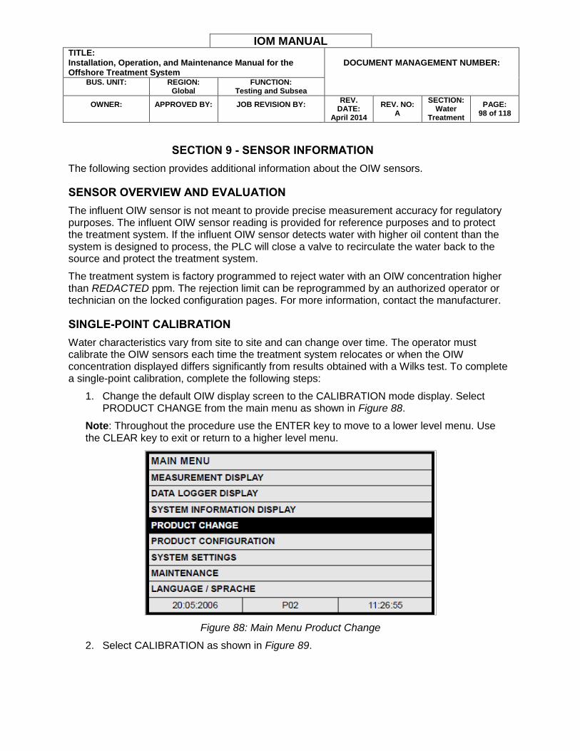
IOM MANUAL TITLE: Installation, Operation, and Maintenance Manual for the Offshore Treatment System
DOCUMENT MANAGEMENT NUMBER:
BUS. UNIT:
REGION:
Global FUNCTION:
Testing and Subsea
OWNER:
APPROVED BY:
JOB REVISION BY:
REV. DATE:
April 2014
REV. NO: A
SECTION: Water
Treatment
PAGE: 98 of 118
SECTION 9 - SENSOR INFORMATION
The following section provides additional information about the OIW sensors.
SENSOR OVERVIEW AND EVALUATION
The influent OIW sensor is not meant to provide precise measurement accuracy for regulatory purposes. The influent OIW sensor reading is provided for reference purposes and to protect the treatment system. If the influent OIW sensor detects water with higher oil content than the system is designed to process, the PLC will close a valve to recirculate the water back to the source and protect the treatment system.
The treatment system is factory programmed to reject water with an OIW concentration higher than REDACTED ppm. The rejection limit can be reprogrammed by an authorized operator or technician on the locked configuration pages. For more information, contact the manufacturer.
SINGLE-POINT CALIBRATION
Water characteristics vary from site to site and can change over time. The operator must calibrate the OIW sensors each time the treatment system relocates or when the OIW concentration displayed differs significantly from results obtained with a Wilks test. To complete a single-point calibration, complete the following steps:
1. Change the default OIW display screen to the CALIBRATION mode display. Select PRODUCT CHANGE from the main menu as shown in Figure 88.
Note: Throughout the procedure use the ENTER key to move to a lower level menu. Use the CLEAR key to exit or return to a higher level menu.
Figure 88: Main Menu Product Change
2. Select CALIBRATION as shown in Figure 89.
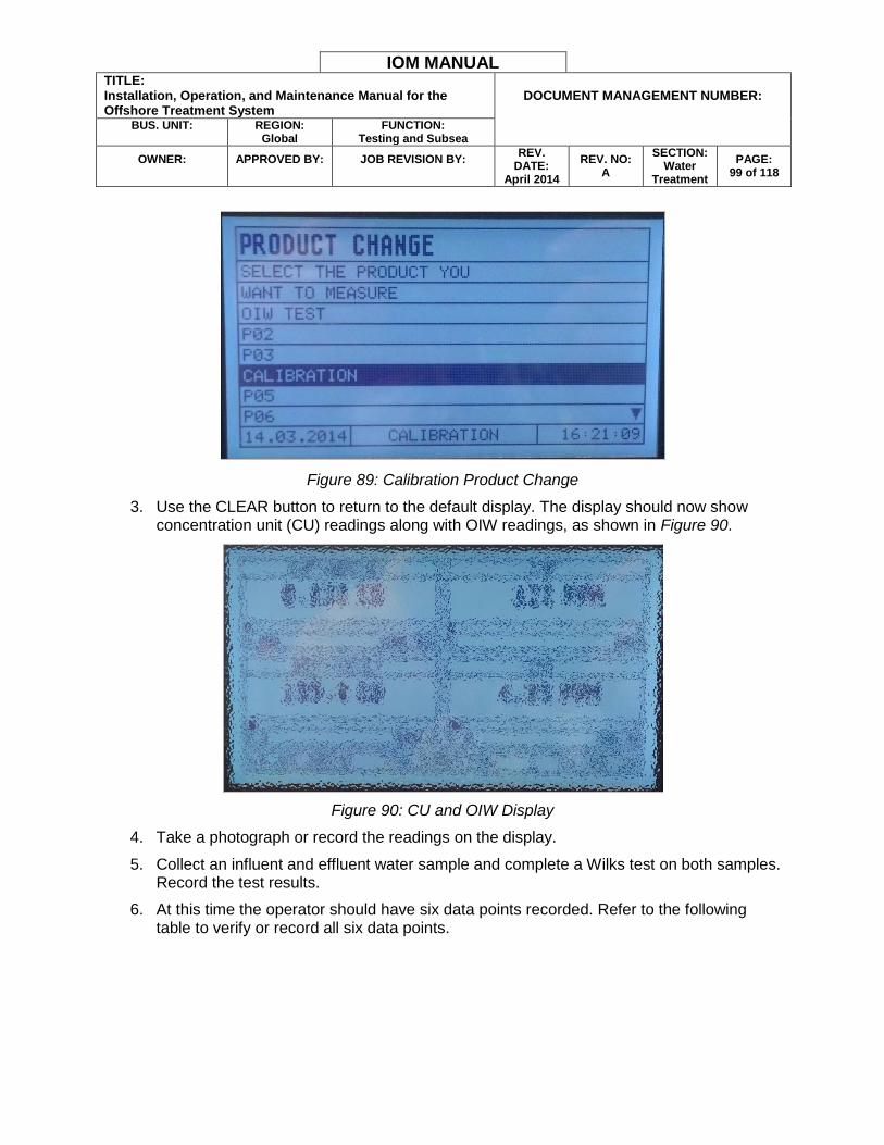
IOM MANUAL TITLE: Installation, Operation, and Maintenance Manual for the Offshore Treatment System
DOCUMENT MANAGEMENT NUMBER:
BUS. UNIT:
REGION:
Global FUNCTION:
Testing and Subsea
OWNER:
APPROVED BY:
JOB REVISION BY:
REV. DATE:
April 2014
REV. NO: A
SECTION: Water
Treatment
PAGE: 99 of 118
Figure 89: Calibration Product Change
3. Use the CLEAR button to return to the default display. The display should now show concentration unit (CU) readings along with OIW readings, as shown in Figure 90.
Figure 90: CU and OIW Display
4. Take a photograph or record the readings on the display.
5. Collect an influent and effluent water sample and complete a Wilks test on both samples. Record the test results.
6. At this time the operator should have six data points recorded. Refer to the following table to verify or record all six data points.
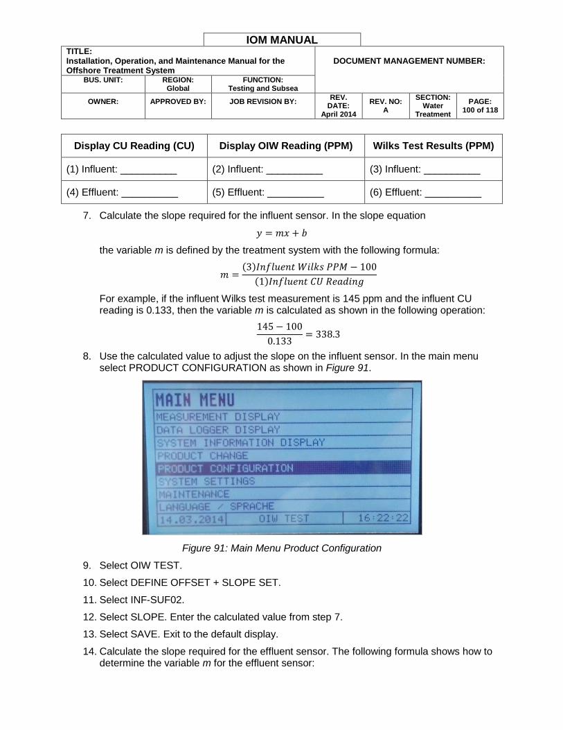
IOM MANUAL TITLE: Installation, Operation, and Maintenance Manual for the Offshore Treatment System
DOCUMENT MANAGEMENT NUMBER:
BUS. UNIT:
REGION:
Global FUNCTION:
Testing and Subsea
OWNER:
APPROVED BY:
JOB REVISION BY:
REV. DATE:
April 2014
REV. NO: A
SECTION: Water
Treatment
PAGE: 100 of 118
Display CU Reading (CU) Display OIW Reading (PPM) Wilks Test Results (PPM)
(1) Influent: __________ (2) Influent: __________ (3) Influent: __________
(4) Effluent: __________ (5) Effluent: __________ (6) Effluent: __________
7. Calculate the slope required for the influent sensor. In the slope equation
𝑦 = 𝑚𝑥 + 𝑏
the variable m is defined by the treatment system with the following formula:
𝑚 =(3)𝐼𝑛𝑓𝑙𝑢𝑒𝑛𝑡 𝑊𝑖𝑙𝑘𝑠 𝑃𝑃𝑀 − 100
(1)𝐼𝑛𝑓𝑙𝑢𝑒𝑛𝑡 𝐶𝑈 𝑅𝑒𝑎𝑑𝑖𝑛𝑔
For example, if the influent Wilks test measurement is 145 ppm and the influent CU reading is 0.133, then the variable m is calculated as shown in the following operation:
145 − 100
0.133= 338.3
8. Use the calculated value to adjust the slope on the influent sensor. In the main menu select PRODUCT CONFIGURATION as shown in Figure 91.
Figure 91: Main Menu Product Configuration
9. Select OIW TEST.
10. Select DEFINE OFFSET + SLOPE SET.
11. Select INF-SUF02.
12. Select SLOPE. Enter the calculated value from step 7.
13. Select SAVE. Exit to the default display.
14. Calculate the slope required for the effluent sensor. The following formula shows how to determine the variable m for the effluent sensor:
IOM MANUAL TITLE: Installation, Operation, and Maintenance Manual for the Offshore Treatment System
DOCUMENT MANAGEMENT NUMBER:
BUS. UNIT:
REGION:
Global FUNCTION:
Testing and Subsea
OWNER:
APPROVED BY:
JOB REVISION BY:
REV. DATE:
April 2014
REV. NO: A
SECTION: Water
Treatment
PAGE: 101 of 118
𝑚 =(6)𝐸𝑓𝑓𝑙𝑢𝑒𝑛𝑡 𝑊𝑖𝑙𝑘𝑠 𝑃𝑃𝑀
(4)𝐸𝑓𝑓𝑙𝑢𝑒𝑛𝑡 𝐶𝑈 𝑅𝑒𝑎𝑑𝑖𝑛𝑔
For example, if the effluent Wilks test measurement is 4.5 ppm and the effluent CU reading is 199.4, then the variable m is calculated as shown in the following operation:
4.5
199.4= 0.0226
15. Use the calculated value to adjust the slope on the effluent sensor. In the main menu select PRODUCT CONFIGURATION.
16. Select OIW TEST.
17. Select DEFINE OFFSET + SLOPE SET.
18. Select EFF-SUF01.
19. Select SLOPE. Enter the calculated value from step 14.
20. Select SAVE. Exit to the default display.
21. Return the display to the standard influent and effluent OIW reading mode. In the main menu select PRODUCT CHANGE. Select OIW TEST.
22. Return to the default display.
ZERO POINT PROGRAMMING
Always check the sensor zero point during commissioning, routine checks, and after lamp module change or other maintenance. To check or set the system zero point, complete the following steps:
1. Clean the sensor windows. Refer to the SENSOR CLEANING section for more information.
2. Fill the sensor body with distilled water.
Note: No gas bubbles must be in the water during the zero point determination process. Allow the water to settle or add additional water until there are no gas bubbles present.
3. Cover the sensor assembly so as to prevent direct sunlight or other light from interfering with the sensor reading.
4. Let the system take readings for at least 15 minutes before checking the measurement.
WARNING: Do not operate any treatment equipment or pump produced water through the system during the sensor stabilization period. The sensor must remain filled with distilled water during this period.
5. Go to the OIL IN WATER display on the EC control cabinet door.
6. Select MAINTENANCE from the main menu and press [ENTER].

IOM MANUAL TITLE: Installation, Operation, and Maintenance Manual for the Offshore Treatment System
DOCUMENT MANAGEMENT NUMBER:
BUS. UNIT:
REGION:
Global FUNCTION:
Testing and Subsea
OWNER:
APPROVED BY:
JOB REVISION BY:
REV. DATE:
April 2014
REV. NO: A
SECTION: Water
Treatment
PAGE: 102 of 118
Figure 92: Main Menu Maintenance Option
7. Select ZERO POINT SETTING MANUALLY and press [ENTER]. The current measuring results appear on the screen. If a faulty signal is received by the system the message “SIGNAL LOSS” appears on the screen. A zero point determination cannot be derived from a faulty signal. Check the sensor water for pollutants or gas bubbles and ensure no ambient light is entering the sensor measurement area.
Figure 93: Zero Point Setting Manually Option
8. To zero the influent sensor, on the Zero Point Setting screen set the EFFLUENT and REDACTED to NO and the INFLUENT and REDACTED to YES. To zero the effluent, set the INFLUENT and REDACTED to NO and the EFFLUENT and REDACTED to YES. The idea is that the opposite sensor from the one currently having the zero point determined should be disabled during the procedure. It is possible to zero both sensors at once, but this makes the procedure more difficult and complex.
IOM MANUAL TITLE: Installation, Operation, and Maintenance Manual for the Offshore Treatment System
DOCUMENT MANAGEMENT NUMBER:
BUS. UNIT:
REGION:
Global FUNCTION:
Testing and Subsea
OWNER:
APPROVED BY:
JOB REVISION BY:
REV. DATE:
April 2014
REV. NO: A
SECTION: Water
Treatment
PAGE: 103 of 118
Figure 94: Zero Point Setting Screen
9. When the CONFIRM SELECTION WITH ENTER message appears press [ENTER].
10. The TO SET NEW ZERO POINT PRESS ENTER message appears. Press [ENTER].
11. The displayed readings will all change to 0.
Note: If an operator programs an effluent offset into the system, the displayed readings will reflect this offset value. For example, if the system currently has a programmed offset of -1, the zero point will be -1, as this value reflects the current offset automatically factored into the measurement.
12. Press CLEAR 3 times until the MEASUREMENT DISPLAY selection is highlighted.
13. Press [ENTER] to return to the normal display.
SENSOR ISSUE REMEDIATION PROCEDURES
If the influent OIW sensor reading is continually causing the PLC to reject the influent water stream, the sensor may need cleaning. Refer to the SENSOR CLEANING section.
If the effluent OIW sensor reading continually deviates from the Wilks test measurement, the sensor may need cleaning. If after cleaning, the deviation between sensor reading and test result persists and is relatively constant, then the sensor may need an offset or gain adjustment.
SENSOR CLEANING
The influent and effluent sensors must be periodically cleaned to maintain accurate OIW readings. Complete the following steps to clean the sensor lenses:
1. Turn off the system and stop all treatment operations.
2. Close the valves upstream and downstream from the sensor assembly. This will isolate the water column containing the sensor assembly.
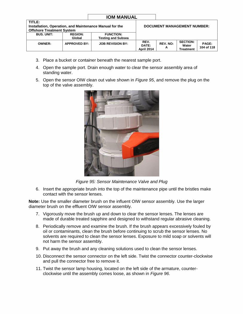
IOM MANUAL TITLE: Installation, Operation, and Maintenance Manual for the Offshore Treatment System
DOCUMENT MANAGEMENT NUMBER:
BUS. UNIT:
REGION:
Global FUNCTION:
Testing and Subsea
OWNER:
APPROVED BY:
JOB REVISION BY:
REV. DATE:
April 2014
REV. NO: A
SECTION: Water
Treatment
PAGE: 104 of 118
3. Place a bucket or container beneath the nearest sample port.
4. Open the sample port. Drain enough water to clear the sensor assembly area of standing water.
5. Open the sensor OIW clean out valve shown in Figure 95, and remove the plug on the top of the valve assembly.
Figure 95: Sensor Maintenance Valve and Plug
6. Insert the appropriate brush into the top of the maintenance pipe until the bristles make contact with the sensor lenses.
Note: Use the smaller diameter brush on the influent OIW sensor assembly. Use the larger diameter brush on the effluent OIW sensor assembly.
7. Vigorously move the brush up and down to clear the sensor lenses. The lenses are made of durable treated sapphire and designed to withstand regular abrasive cleaning.
8. Periodically remove and examine the brush. If the brush appears excessively fouled by oil or contaminants, clean the brush before continuing to scrub the sensor lenses. No solvents are required to clean the sensor lenses. Exposure to mild soap or solvents will not harm the sensor assembly.
9. Put away the brush and any cleaning solutions used to clean the sensor lenses.
10. Disconnect the sensor connector on the left side. Twist the connector counter-clockwise and pull the connector free to remove it.
11. Twist the sensor lamp housing, located on the left side of the armature, counter-clockwise until the assembly comes loose, as shown in Figure 96.

IOM MANUAL TITLE: Installation, Operation, and Maintenance Manual for the Offshore Treatment System
DOCUMENT MANAGEMENT NUMBER:
BUS. UNIT:
REGION:
Global FUNCTION:
Testing and Subsea
OWNER:
APPROVED BY:
JOB REVISION BY:
REV. DATE:
April 2014
REV. NO: A
SECTION: Water
Treatment
PAGE: 105 of 118
Figure 96: Sensor Lamp Housing Removed
12. Look into the exposed sensor armature window to verify the sensor lenses are clean.
13. Reinstall the sensor.
ADJUSTING SENSOR OFFSET AND SLOPE
The operator can perform offset and slope adjustments on the effluent OIW sensor to compensate for specific water characteristics. An offset adds or subtracts a fixed value, measured in ppm, from the OIW sensor measurement. A slope adjustment adjusts how the sensor scales the signal received from a given reading.
WARNING: Only authorized personnel may perform this procedure. This procedure will change the effluent OIW sensor measurement results.
1. Select the DEFINE OFFSET + SLOPE SET function in the PRODUCT menu and press [ENTER].
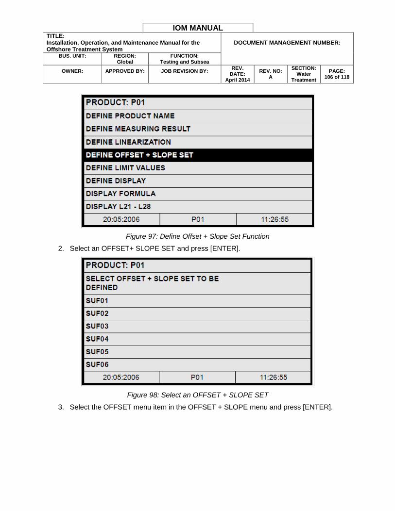
IOM MANUAL TITLE: Installation, Operation, and Maintenance Manual for the Offshore Treatment System
DOCUMENT MANAGEMENT NUMBER:
BUS. UNIT:
REGION:
Global FUNCTION:
Testing and Subsea
OWNER:
APPROVED BY:
JOB REVISION BY:
REV. DATE:
April 2014
REV. NO: A
SECTION: Water
Treatment
PAGE: 106 of 118
Figure 97: Define Offset + Slope Set Function
2. Select an OFFSET+ SLOPE SET and press [ENTER].
Figure 98: Select an OFFSET + SLOPE SET
3. Select the OFFSET menu item in the OFFSET + SLOPE menu and press [ENTER].

IOM MANUAL TITLE: Installation, Operation, and Maintenance Manual for the Offshore Treatment System
DOCUMENT MANAGEMENT NUMBER:
BUS. UNIT:
REGION:
Global FUNCTION:
Testing and Subsea
OWNER:
APPROVED BY:
JOB REVISION BY:
REV. DATE:
April 2014
REV. NO: A
SECTION: Water
Treatment
PAGE: 107 of 118
Figure 99: Define OFFSET Value
4. Type in the OFFSET value with the numeric keyboard. Press [ENTER].
Note: Change the offset value according to the measurement discrepancy observed between the effluent OIW sensor and the Wilks test result. For example, if the effluent OIW sensor is consistently 2 ppm higher than the Wilks test measurement, enter -2 as the offset. Use repeated test measurements to ensure greater accuracy.
5. The screen then moves to the SLOPE menu item. Type in the SLOPE value with the numeric keyboard. Press [ENTER].
Figure 100: Define SLOPE Value
IOM MANUAL TITLE: Installation, Operation, and Maintenance Manual for the Offshore Treatment System
DOCUMENT MANAGEMENT NUMBER:
BUS. UNIT:
REGION:
Global FUNCTION:
Testing and Subsea
OWNER:
APPROVED BY:
JOB REVISION BY:
REV. DATE:
April 2014
REV. NO: A
SECTION: Water
Treatment
PAGE: 108 of 118
Note: Change the slope value in very small increments. The slope value affects the measurement reading over the entire range of the sensor. A higher value will result in a higher ppm reading. Begin with a change of 0.001 or 0.002 and test the resulting measurement changes.
6. Save the new settings.
FACTORY SLOPE + OFFSET SETTINGS:
OFFSET: REDACTED
SLOPE: REDACTED
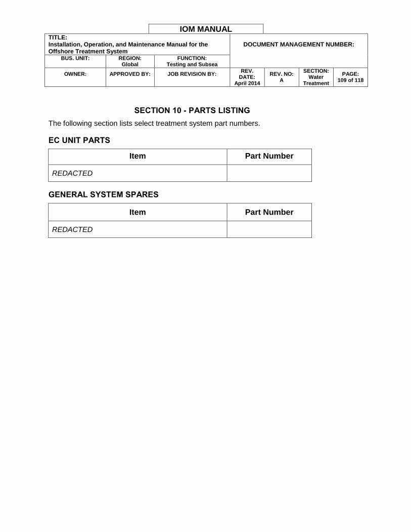
IOM MANUAL TITLE: Installation, Operation, and Maintenance Manual for the Offshore Treatment System
DOCUMENT MANAGEMENT NUMBER:
BUS. UNIT:
REGION:
Global FUNCTION:
Testing and Subsea
OWNER:
APPROVED BY:
JOB REVISION BY:
REV. DATE:
April 2014
REV. NO: A
SECTION: Water
Treatment
PAGE: 109 of 118
SECTION 10 - PARTS LISTING
The following section lists select treatment system part numbers.
EC UNIT PARTS
Item Part Number
REDACTED
GENERAL SYSTEM SPARES
Item Part Number
REDACTED
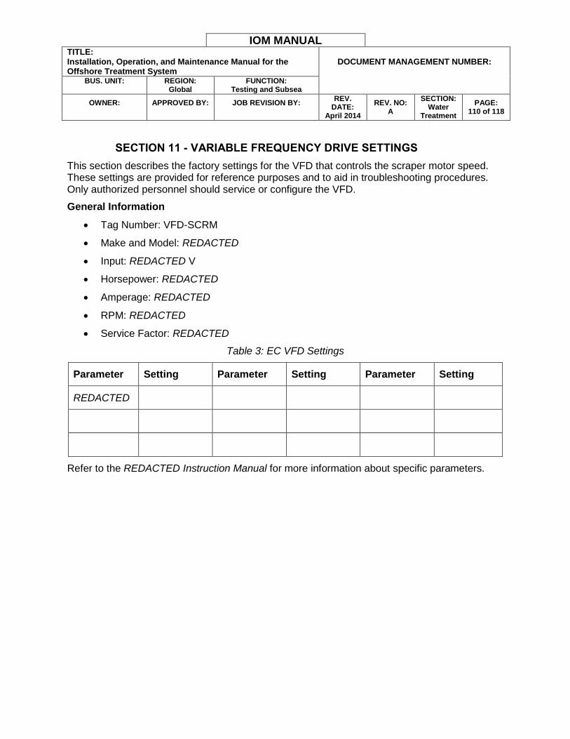
IOM MANUAL TITLE: Installation, Operation, and Maintenance Manual for the Offshore Treatment System
DOCUMENT MANAGEMENT NUMBER:
BUS. UNIT:
REGION:
Global FUNCTION:
Testing and Subsea
OWNER:
APPROVED BY:
JOB REVISION BY:
REV. DATE:
April 2014
REV. NO: A
SECTION: Water
Treatment
PAGE: 110 of 118
SECTION 11 - VARIABLE FREQUENCY DRIVE SETTINGS
This section describes the factory settings for the VFD that controls the scraper motor speed. These settings are provided for reference purposes and to aid in troubleshooting procedures. Only authorized personnel should service or configure the VFD.
General Information
Tag Number: VFD-SCRM
Make and Model: REDACTED
Input: REDACTED V
Horsepower: REDACTED
Amperage: REDACTED
RPM: REDACTED
Service Factor: REDACTED
Table 3: EC VFD Settings
Parameter Setting Parameter Setting Parameter Setting
REDACTED
Refer to the REDACTED Instruction Manual for more information about specific parameters.

IOM MANUAL TITLE: Installation, Operation, and Maintenance Manual for the Offshore Treatment System
DOCUMENT MANAGEMENT NUMBER:
BUS. UNIT:
REGION:
Global FUNCTION:
Testing and Subsea
OWNER:
APPROVED BY:
JOB REVISION BY:
REV. DATE:
April 2014
REV. NO: A
SECTION: Water
Treatment
PAGE: 111 of 118
SECTION 12 - RELATED DOCUMENTATION
REDACTED Digital Inductive Conductivity Sensor User Manual
REDACTED Installation and Operating Instructions
REDACTED Analyzer Model REDACTED and CH User’s Guide
Instruction Manual REDACTED
Instruction Manual REDACTED
Instruction Manual REDACTED
REDACTED Technical Booklet Approach to REDACTED Micro-Bubble Generator
REDACTED Electromagnetic Flow meters Operating Instructions
REDACTED pH and ORP Electrodes Instructions
Technical Construction File OEG Offshore DNV 2.7-1/DNV2.7-2 A60 Zone 2 Electrical Surface Control Cabin
REDACTED Instruction Manual
IOM MANUAL TITLE: Installation, Operation, and Maintenance Manual for the Offshore Treatment System
DOCUMENT MANAGEMENT NUMBER:
BUS. UNIT:
REGION:
Global FUNCTION:
Testing and Subsea
OWNER:
APPROVED BY:
JOB REVISION BY:
REV. DATE:
April 2014
REV. NO: A
SECTION: Water
Treatment
PAGE: 112 of 118
SECTION 13 - MAINTENANCE WORKSHEETS AND SCHEDULES
The following maintenance inspection worksheets are provided for reference purposes. Additional maintenance operations may be necessary at different sites or in adverse operating conditions. The inspection routines should only be performed by qualified operators and Water Tectonics personnel.
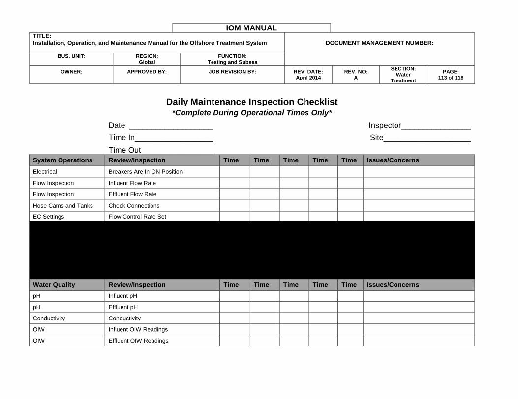
IOM MANUAL TITLE: Installation, Operation, and Maintenance Manual for the Offshore Treatment System
DOCUMENT MANAGEMENT NUMBER:
BUS. UNIT:
REGION:
Global FUNCTION:
Testing and Subsea
OWNER:
APPROVED BY:
JOB REVISION BY:
REV. DATE: April 2014
REV. NO: A
SECTION: Water
Treatment
PAGE: 113 of 118
Daily Maintenance Inspection Checklist *Complete During Operational Times Only*
Date ___________________
Inspector________________
Time In__________________
Site____________________
Time Out_________________
System Operations Review/Inspection Time Time Time Time Time Issues/Concerns
Electrical Breakers Are In ON Position
Flow Inspection Influent Flow Rate
Flow Inspection Effluent Flow Rate
Hose Cams and Tanks Check Connections
EC Settings Flow Control Rate Set
EC Settings EC Stage (Amps/Volts)
IAF Settings Pressures
IAF Settings Float Switch Positions at Proper Level
Chemical Injection NaOH Consumable Level
Chemical Injection Polymer Consumable Level
Water Quality Review/Inspection Time Time Time Time Time Issues/Concerns
pH Influent pH
pH Effluent pH
Conductivity Conductivity
OIW Influent OIW Readings
OIW Effluent OIW Readings
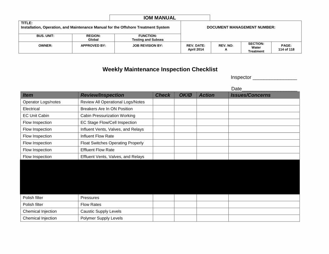
IOM MANUAL TITLE: Installation, Operation, and Maintenance Manual for the Offshore Treatment System
DOCUMENT MANAGEMENT NUMBER:
BUS. UNIT:
REGION:
Global FUNCTION:
Testing and Subsea
OWNER:
APPROVED BY:
JOB REVISION BY:
REV. DATE: April 2014
REV. NO: A
SECTION: Water
Treatment
PAGE: 114 of 118
Weekly Maintenance Inspection Checklist
Inspector ________________
Date____________________
Item Review/Inspection Check OK/Ø Action Issues/Concerns
Operator Logs/notes Review All Operational Logs/Notes
Electrical Breakers Are In ON Position
EC Unit Cabin Cabin Pressurization Working
Flow Inspection EC Stage Flow/Cell Inspection
Flow Inspection Influent Vents, Valves, and Relays
Flow Inspection Influent Flow Rate
Flow Inspection Float Switches Operating Properly
Flow Inspection Effluent Flow Rate
Flow Inspection Effluent Vents, Valves, and Relays
IAF Function IAF Pumps, Valves, Scraper System
OIW Sensor Influent Readings Match Wilks
OIW Sensor Effluent Readings Match Wilks
Bag filter Pressures
Bag filter Flow Rates
Polish filter Pressures
Polish filter Flow Rates
Chemical Injection Caustic Supply Levels
Chemical Injection Polymer Supply Levels
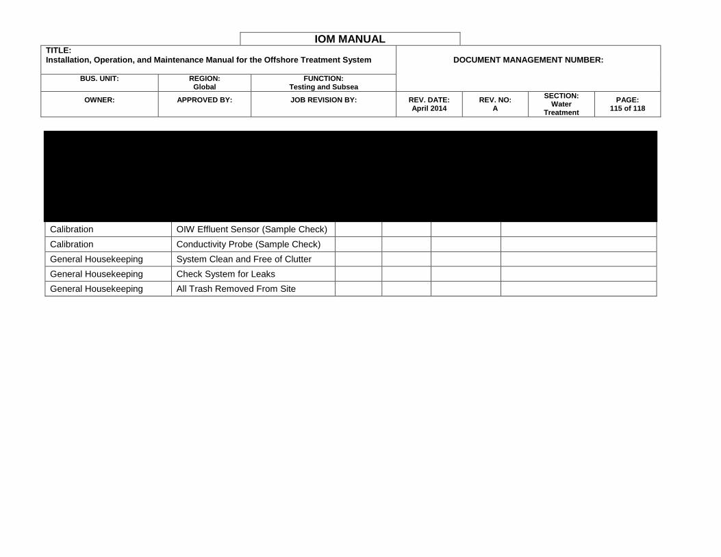
IOM MANUAL TITLE: Installation, Operation, and Maintenance Manual for the Offshore Treatment System
DOCUMENT MANAGEMENT NUMBER:
BUS. UNIT:
REGION:
Global FUNCTION:
Testing and Subsea
OWNER:
APPROVED BY:
JOB REVISION BY:
REV. DATE: April 2014
REV. NO: A
SECTION: Water
Treatment
PAGE: 115 of 118
Chemical Injection Caustic Chemical Pump
Chemical Injection Caustic Injection Quill
Chemical Injection Polymer Chemical Pump
Chemical Injection Polymer Injection Quill
Pressurization System Check System Pressures
Calibration pH Probe (Grab Sample Check)
Calibration OIW Effluent Sensor (Sample Check)
Calibration Conductivity Probe (Sample Check)
General Housekeeping System Clean and Free of Clutter
General Housekeeping Check System for Leaks
General Housekeeping All Trash Removed From Site
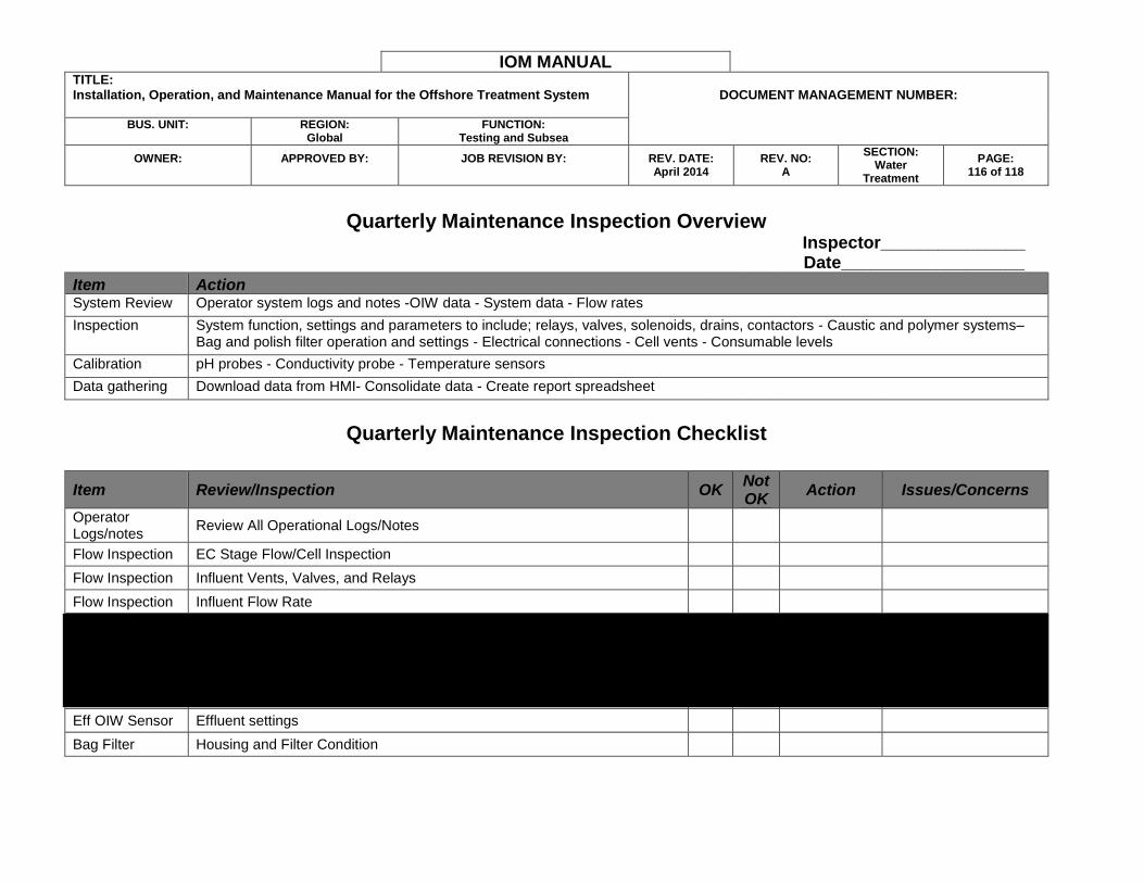
IOM MANUAL TITLE: Installation, Operation, and Maintenance Manual for the Offshore Treatment System
DOCUMENT MANAGEMENT NUMBER:
BUS. UNIT:
REGION:
Global FUNCTION:
Testing and Subsea
OWNER:
APPROVED BY:
JOB REVISION BY:
REV. DATE: April 2014
REV. NO: A
SECTION: Water
Treatment
PAGE: 116 of 118
Quarterly Maintenance Inspection Overview
Inspector_______________ Date___________________
Item Action System Review Operator system logs and notes -OIW data - System data - Flow rates
Inspection System function, settings and parameters to include; relays, valves, solenoids, drains, contactors - Caustic and polymer systems–Bag and polish filter operation and settings - Electrical connections - Cell vents - Consumable levels
Calibration pH probes - Conductivity probe - Temperature sensors
Data gathering Download data from HMI- Consolidate data - Create report spreadsheet
Quarterly Maintenance Inspection Checklist
Item Review/Inspection OK Not OK
Action Issues/Concerns
Operator Logs/notes
Review All Operational Logs/Notes
Flow Inspection EC Stage Flow/Cell Inspection
Flow Inspection Influent Vents, Valves, and Relays
Flow Inspection Influent Flow Rate
Flow Inspection Effluent Flow Rate
Flow Inspection Effluent Valves and Relays
Flow Inspection Solenoids and Contactors
Inf OIW Sensor Influent settings
Eff OIW Sensor Effluent settings
Bag Filter Housing and Filter Condition
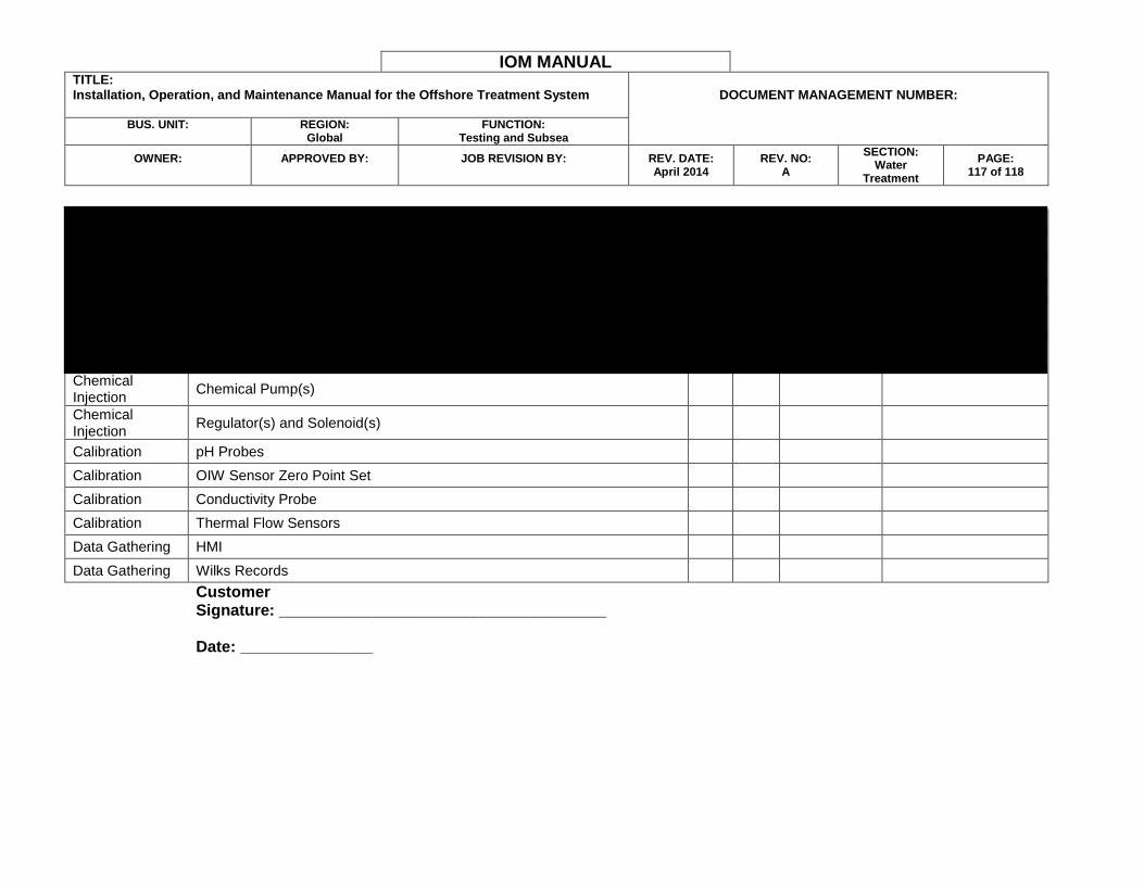
IOM MANUAL TITLE: Installation, Operation, and Maintenance Manual for the Offshore Treatment System
DOCUMENT MANAGEMENT NUMBER:
BUS. UNIT:
REGION:
Global FUNCTION:
Testing and Subsea
OWNER:
APPROVED BY:
JOB REVISION BY:
REV. DATE: April 2014
REV. NO: A
SECTION: Water
Treatment
PAGE: 117 of 118
Bag Filter Pressures
Polish Filter Housing and Filter Condition
Polish Filter Pressures
Media Filter Control Panel Settings
Pumps and Motors
Check Lubrication and Grease
Chemical Injection
Caustic and Polymer Consumables levels
Chemical Injection
Chemical Pump(s)
Chemical Injection
Regulator(s) and Solenoid(s)
Calibration pH Probes
Calibration OIW Sensor Zero Point Set
Calibration Conductivity Probe
Calibration Thermal Flow Sensors
Data Gathering HMI
Data Gathering Wilks Records
Customer Signature: _____________________________________ Date: _______________
IOM MANUAL TITLE: Installation, Operation, and Maintenance Manual for the Offshore Treatment System
DOCUMENT MANAGEMENT NUMBER:
BUS. UNIT:
REGION:
Global FUNCTION:
Testing and Subsea
OWNER:
APPROVED BY:
JOB REVISION BY:
REV. DATE: April 2014
REV. NO: A
SECTION: Water
Treatment
PAGE: 118 of 118
SECTION 14 - PIPING AND INSTRUMENTATION DIAGRAM
REDACTED