Embed Size (px)
Citation preview

Installation, Operation, and
Maintenance Manual
Aquapurion 600 GPD Line
Pressure Reverse Osmosis
System
US Water Systems, Inc. 1209 Country Club Road
Indianapolis, IN 46234 1-800-608-8792
[email protected] www.uswatersystems.com
Installation, Operation and Maintenance Manual
2
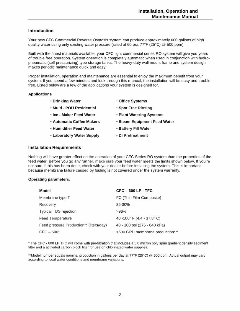
Introduction Your new CFC Commercial Reverse Osmosis system can produce approximately 600 gallons of high quality water using only existing water pressure (rated at 60 psi, 77°F (25°C) @ 500 ppm). Built with the finest materials available, your CFC light commercial series RO system will give you years of trouble free operation. System operation is completely automatic when used in conjunction with hydro-pneumatic (self pressurizing) type storage tanks. The heavy-duty wall mount frame and system design makes periodic maintenance quick and easy. Proper installation, operation and maintenance are essential to enjoy the maximum benefit from your system. If you spend a few minutes and look through this manual, the installation will be easy and trouble free. Listed below are a few of the applications your system is designed for. Applications
• Drinking Water • Office Systems
• Multi - POU Residential • Spot Free Rinsing
• Ice - Maker Feed Water • Plant Watering Systems
• Automatic Coffee Makers • Steam Equipment Feed Water
• Humidifier Feed Water • Battery Fill Water
• Laboratory Water Supply • DI Pretreatment
Installation Requirements Nothing will have greater effect on the operation of your CFC Series RO system than the properties of the feed water. Before you go any further, make sure your feed water meets the limits shown below. If you’re not sure if this has been done, check with your dealer before installing the system. This is important because membrane failure caused by fouling is not covered under the system warranty. Operating parameters:
Model CFC – 600 LP - TFC
Membrane type T FC (Thin Film Composite)
Recovery 25-30%
Typical TDS rejection >96%
Feed Temperature 40 -100° F (4.4 - 37.8° C)
Feed pressure Production** (liters/day) 40 - 100 psi (275 - 640 kPa)
CFC – 600* >600 GPD membrane production***
* The CFC - 600 LP TFC will come with pre-filtration that includes a 5.0 micron poly spun gradient density sediment filter and a activated carbon block filter for use on chlorinated water supplies. **Model number equals nominal production in gallons per day at 77°F (25°C) @ 500 ppm. Actual output may vary according to local water conditions and membrane variations.

Installation, Operation and Maintenance Manual
3
Feedwater Chemistry:
Parameter CFC – 600 LP TFC
Feed TDS Up to 2000 ppm
Feed pH 4.0 -11
Hardness 20 grains or less
Free chlorine non allowable
Iron (Fe) <0.1 mg/l
Manganese <.05 mg/l
Hydrogen sulfide none allowable
Pretreatment:
Proper pretreatment is critical to RO system performance. All CFC RO systems include a commercial grade 5.0 micron sediment prefilter. Systems used on chlorinated water supplies may require two activated carbon filters to remove free chlorine. In high hardness areas polyphosphate prefilter or a water softener maybe necessary to prevent membrane fouling.
Getting To Know Your CFC RO System: Before you get started with the installation, take a few minutes to learn the names of your CFC RO system parts and controls. With the unit unpacked and sitting in front of you, compare it with the picture below. This will familiarize you with the major components of the system. Then, look at the picture of a typical installation on the next page. When you are familiar with the basic layout of the system, you are ready to start the installation. Installation Procedure (Figure #1)
Typical Installation Drawing: (Figure #2)
Installation, Operation and Maintenance Manual
4
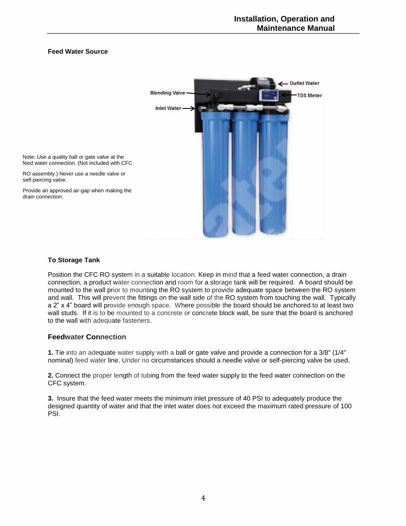
Feed Water Source
To Storage Tank
Position the CFC RO system in a suitable location. Keep in mind that a feed water connection, a drain connection, a product water connection and room for a storage tank will be required. A board should be mounted to the wall prior to mounting the RO system to provide adequate space between the RO system and wall. This will prevent the fittings on the wall side of the RO system from touching the wall. Typically a 2” x 4” board will provide enough space. Where possible the board should be anchored to at least two wall studs. If it is to be mounted to a concrete or concrete block wall, be sure that the board is anchored to the wall with adequate fasteners.
Feedwater Connection 1. Tie into an adequate water supply with a ball or gate valve and provide a connection for a 3/8" (1/4" nominal) feed water line. Under no circumstances should a needle valve or self-piercing valve be used. 2. Connect the proper length of tubing from the feed water supply to the feed water connection on the CFC system. 3. Insure that the feed water meets the minimum inlet pressure of 40 PSI to adequately produce the designed quantity of water and that the inlet water does not exceed the maximum rated pressure of 100 PSI.
Note: Use a quality ball or gate valve at the feed water connection. (Not included with CFC
RO assembly.) Never use a needle valve or self-piercing valve.
Provide an approved air-gap when making the drain connection.
Installation, Operation and Maintenance Manual
5
Product Water Connection
Run 3/8" (1/4" nominal) tubing from the product water connection to a 3/8" tee at the inlet valve of a hydropneumatic storage tank or to a bulkhead fitting at the top of an atmospheric tank. Product water and drain connections on the CFC system are 1/4" John Guest fittings. A 1/4” to 3/8” coupling is provided to adapt the product water line at the shutoff valve (pump) from 1/4” to 3/8” for point of use distribution and hydropneumatic tank connection. To properly connect the 3/8" (1/4" nom.) tubing;
a. Be certain the tubing end is clean and cut perpendicular to tubing length. b. Moisten the end of the tubing with water and push it straight into the fitting until it bottoms on the fitting shoulder.
Drain Connection
Run 1/4" tubing from the reject drain connection at the shutoff valve (pump) to the drain connection. Important: An approved air gap should exist between the RO unit and the drain opening to meet local plumbing codes. A special in-line air gap is available.
Point of Use Connection(s)
Run the final product line(s) from the storage tank to the point(s) of use. • Select the tubing size that will ensure adequate flow and pressure to the point of use, (eg. longer runs require larger tubing).
• The type of tubing used must meet local plumbing codes. Tubing used for drinking water applications must be made of FDA approved materials.
• For drinking water applications, carbon filters should be installed as close to each point of use as possible. • A quality ball type shut-off valve should be installed at each point of use to simplify future maintenance (eg. filter changes).
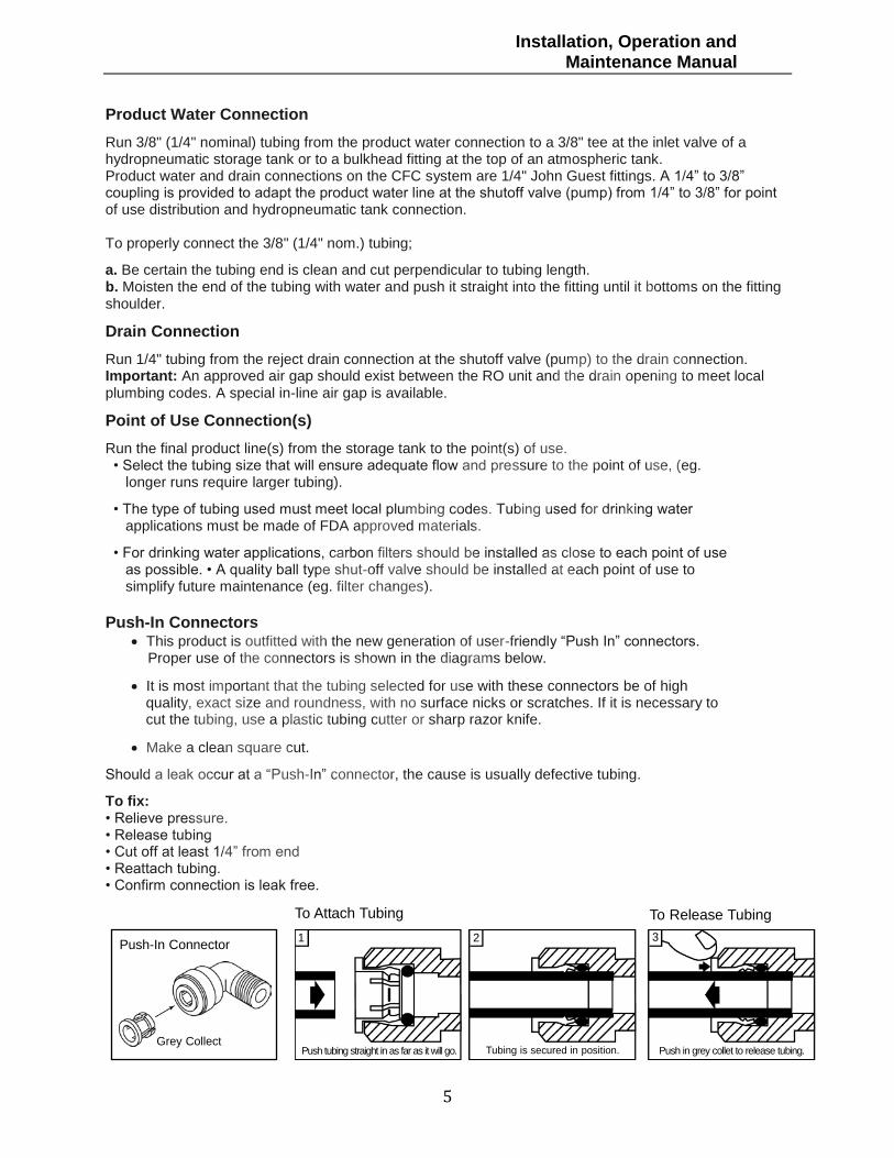
Push-In Connectors
This product is outfitted with the new generation of user-friendly “Push In” connectors. Proper use of the connectors is shown in the diagrams below.
It is most important that the tubing selected for use with these connectors be of high quality, exact size and roundness, with no surface nicks or scratches. If it is necessary to cut the tubing, use a plastic tubing cutter or sharp razor knife.
Make a clean square cut.
Should a leak occur at a “Push-In” connector, the cause is usually defective tubing.
To fix: • Relieve pressure. • Release tubing • Cut off at least 1/4” from end • Reattach tubing. • Confirm connection is leak free.NOT
4
Product Water Connection
1. Run 3/8" (1/4" nominal) tubing from the product water connection (fig. 1) to a 3/8" tee at the inlet valve of
a hydropneumatic storage tank or to a bulkhead fitting at the top of an atmospheric tank.
pH adjustment; If a pH adjustment filter (optional) is used, it should be installed in the product line between
the RO system and storage tank to ensure adequate contact time.
Product water and drain connections on the LP system are 3/8" John Guest fittings. To properly connect
the 3/8" (1/4" nom.) tubing (provided);
a. Be certain the tubing end is clean and cut perpendicular to tubing length.
b. Moisten the end of the tubing with water and push it straight into the fitting until it bottoms on the fitting shoulder.
Drain Connection
1. Run 3/8" (1/4" nom.) tubing from the reject drain connection (fig. #1) to the drain connection. Important: An approved air gap should exist between the RO unit and the drain opening to meet local
plumbing codes. A special in-line air gap is available.
Point of Use Connection(s)
1. Run the final product line(s) from the storage tank to the point(s) of use.
� Select the tubing size that will ensure adequate flow and pressure to the point of use, (eg. longer runs require
larger tubing).
� The type of tubing used must meet local plumbing codes. Tubing used for drinking water applications must
be made of FDA approved materials.
� For drinking water applications, carbon filters should be installed as close to each point of use as possible.
� Aquality ball type shut-off valve should be installed at each point of use to simplify future maintenance (eg. filter changes).
Push-In Connectors
This product is outfitted with the new generation of user-friendly �Push In� connectors. Proper use of the connectors
is shown in the diagrams below.
It is most important that the tubing selected for use with these connectors be of high quality, exact size and roundness,
with no surface nicks or scratches. If it is necessary to cut the tubing, use a plastic tubing cutter or sharp razor knife.
Make a clean square cut.
Should a leak occur at a �Push-In� connector, the cause is usually defective tubing.
To fix:� Relieve pressure.
� Release tubing.
� Cut off at least 1/4� from end
� Reattach tubing.
� Confirm connection is leak free.
NOTE
NOTE
Push-In Connector
Grey Collect
1 32
Push tubing straight in as far as it will go. Tubing is secured in position. Push in grey collet to release tubing.
To Attach Tubing To Release Tubing
Installation, Operation and
Maintenance Manual

Installation, Operation and Maintenance Manual
6
Start-Up Procedures
1. Double check that all connections are secure.
2. Close the valve on the hydropneumatic storage tank(s). This will allow the product side of the RO system to pressurize within a few minutes without waiting for the storage tank to fill.
3. Open the feed water valve(s), wait a few minutes and check for leaks. If any leaks are detected turn off feed water inlet valve and correct.
Setting the TDS Meter
To set the TDS (Total Dissolved Solids) monitor press (fig 1) the on and off button to start.
Move the switch to the right showing the TDS on the product waterside of the membrane. Note that moving the switch to the left with show the inlet TDS before the RO membrane
Setting the Product Water TDS
1. Make sure that the Blending Valve (fig 1) is turned completely in the counter clock wise position before attempting to set the outlet water TDS (Total Dissolved Solids) to the desired level. 2. To adjust the product water TDS, slowly turn the blending valve in a counter wise motion checking the TDS monitor digital box until you reach the product water TDS that you desire. 3. Over time the blending valve may need adjusted as the TDS level may change. This is due to a reduction in membrane performance as the membrane will degrade over time.
Routine Maintenance Routine maintenance is necessary to ensure consistent performance and long system life. The required routine maintenance consists of changing the sediment and carbon prefilters. Since maintenance frequency will range from 3 months to 1 year depending on the properties of your feed water, it’s important that you consult with your distributor or the factory for recommended maintenance frequency for your system.
Installation, Operation and Maintenance Manual
7
De-pressurization Procedure
Prior to changing any prefilters, the feed water must be shut off and the system must be depressurized. To do this:
1. Close the feed water inlet shut-off valve on the CFC RO system.
2. Close the shut-off valve on hydropneumatic storage tank(s).
3. Open any point of use and leave it open.
4. The unit is now depressurized and ready for prefilter replacement. Although the system is depressurized, the filter bowls will still be full of water when removed.
Sediment Prefilter Replacement Procedure
1. De-pressurize the system.
2. Locate the sediment prefilter (see fig. #1). To remove the sediment prefilter, unscrew the filter bowl to the left (counterclockwise as viewed from the bottom) using a filter bowl wrench or by hand. Empty the water and remove the filter from the bowl and discard it.
3. Inspect the O-ring seals for damage. The O-rings should be replaced if they are damaged or distorted. Clean the filter bowls with warm water and soap. Chemically disinfect the filter bowls if desired (household bleach can be used, 1/2 teaspoon in a filter bowl of water).
4. Insert the new prefilter into the filter bowl. Screw the filter bowl (clockwise) onto the filter head by hand or use the filter wrench. Be careful not to over tighten if you are using the filter wrench. Carbon Prefilter Replacement Procedure
1. De-pressurize the system.
2. Locate the carbon prefilter (see fig. #1). To remove the carbon prefilter, unscrew the filter bowls to the left (counterclockwise as viewed from the bottom), using a filter bowl wrench or by hand. Remove the filters from the bowls and discard them.
3. Inspect the O-ring seals for damage. The O-rings should be replaced if they are damaged or distorted. Clean the filter bowls with warm water and soap. Chemically disinfect the filter bowls if desired (household bleach can be used, 1/2 teaspoon in a filter bowl of water).
4. Insert the new prefilter into the filter bowl. Screw the filter bowl (clockwise) onto the filter head by hand or use the filter wrench. Be careful not to over tighten if you are using the filter wrench.
System Re-Start
1. Ensure that the filter bowls are tightly sealed
2. Leave the point of use open and the hydropneumatic storage tank valve closed.
3. Open the feed water valve. Wait 3 to 5 minutes to allow the system to purge air and stabilize.
4. Close any open points of use. Open the valve on the hydropneumatic storage tank.
5. The filter replacement procedure is now complete.
Installation, Operation and Maintenance Manual
8