Embed Size (px)
Citation preview
Unicon HC 5–25, HC 30–40
Installation, Operation and MaintenanceInstructions
ERIEZ MAGNETICS HEADQUARTERS: 2200 ASBURY ROAD, ERIE, PA 16506–1402 U.S.A.WORLD AUTHORITY IN SEPARATION TECHNOLOGIES
VM-11
UniconUnHc 5–25 UnHc 30–40Feeder control Unit
2
IntroductionThis description contains the necessary information for the correct application of the product described below. It is intended for use by technically qualified personal.
Qualified personnel are persons who, because of their training, experience and position as well as their knowledge of appropriate standards, regulations, health and safety requirements and working conditions, are authorised to be responsible for the safety of the equipment, at all times, whilst carrying out their normal duties and are therefore aware of, and can report, possible hazards (Definition of qualified employees according to IEC 364)
Warning! Hazardous Voltage
Failure to observe can kill, cause serious injury or damage
The following instructions are provided for the personal safety of operators and also for the protection of the described product and connected equipment.
• Isolate from mains before installation or dismantling work, as well as for fuse changes or post installation modifications.
• Observe the prescribed accident prevention and safety rules for the specific application.
• Before putting into operation check if the rated voltage for the unit conforms with the local supply voltage.
• Emergency stop devices must be provided for all applications. Operation of the emergency stop must inhibit any further uncontrolled operation.
• Electrical connections must be covered
• The earth connection must be checked, for correct function, after installation.
Specified Use
The units described herein are electrical controllers for installation in industrial plant. They are designed for power adjustment on vibratory feed equipment.
Contact Eriez if you have a question regarding these precautions.
CAUTIONSafety labels must be affixed to this product. Should the safety label(s) be damaged, dislodged or removed, contact Eriez for replacement.
© 2016 ERIEZ MAGNETICS ALL RIGHTS RESERVED
Unicon HC 5–25, HC 30–40
3
Table of ContentsUNICON HC 5–25, HC 30–40
USER TECHNICAL SAfETy INfoRMATIoN....................................................... 2
GENERAL ............................................................................................................. 4
TECHNICAL DATA ................................................................................................ 5
VoLTAGE SELECTIoN ......................................................................................... 6
CoNTRoL oVERVIEw ......................................................................................... 6
CoNNECTIoNS IP20/NEMA 1 VERSIoN ............................................................ 7
CoNNECTIoNS IP65/NEMA 4 VERSIoN ............................................................ 8
fUNCTIoN ............................................................................................................ 9
Vibrating frequency......................................................................................... 9
Setpoint ......................................................................................................... 10
Acceleration Regulator .................................................................................. 10
MoUNTING THE ACCELERoMETER ................................................................ 10
STARTUP of A VIbRAToRy fEEDER wITH ACCELERATIoN CoNTRoL ..... 12
DIMENSIoNS ...................................................................................................... 13
PARTS LIST ........................................................................................................ 17
4
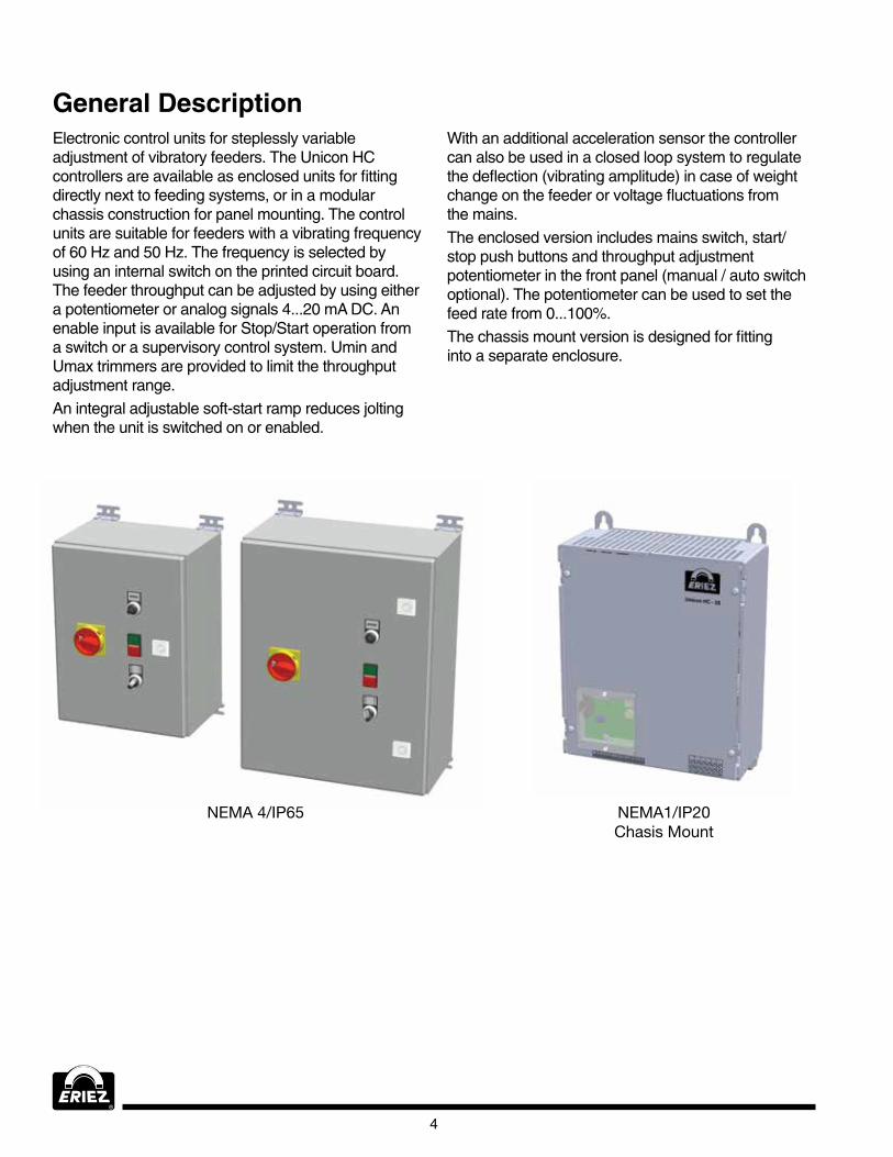
General DescriptionElectronic control units for steplessly variable adjustment of vibratory feeders. The Unicon HC controllers are available as enclosed units for fitting directly next to feeding systems, or in a modular chassis construction for panel mounting. The control units are suitable for feeders with a vibrating frequency of 60 Hz and 50 Hz. The frequency is selected by using an internal switch on the printed circuit board. The feeder throughput can be adjusted by using either a potentiometer or analog signals 4...20 mA DC. An enable input is available for Stop/Start operation from a switch or a supervisory control system. Umin and Umax trimmers are provided to limit the throughput adjustment range. An integral adjustable soft-start ramp reduces jolting when the unit is switched on or enabled.
NEMA 4/IP65 NEMA1/IP20 Chasis Mount
with an additional acceleration sensor the controller can also be used in a closed loop system to regulate the deflection (vibrating amplitude) in case of weight change on the feeder or voltage fluctuations from the mains.The enclosed version includes mains switch, start/stop push buttons and throughput adjustment potentiometer in the front panel (manual / auto switch optional). The potentiometer can be used to set the feed rate from 0...100%. The chassis mount version is designed for fitting into a separate enclosure.
Unicon HC 5–25, HC 30–40
5
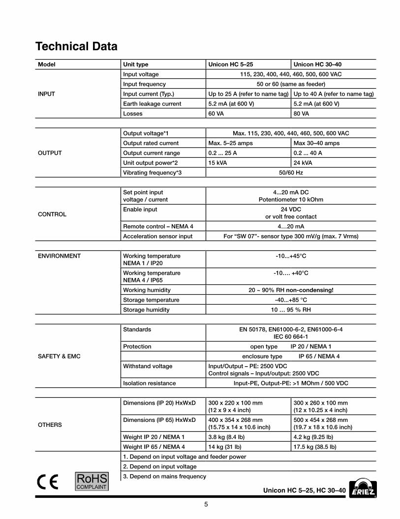
Technical DataModel Unit type Unicon HC 5–25 Unicon HC 30–40
INPUT
Input voltage 115, 230, 400, 440, 460, 500, 600 VAC
Input frequency 50 or 60 (same as feeder)
Input current (Typ.) Up to 25 A (refer to name tag) Up to 40 A (refer to name tag)
Earth leakage current 5.2 mA (at 600 V) 5.2 mA (at 600 V)
Losses 60 VA 80 VA
OUTPUT
Output voltage*1 Max. 115, 230, 400, 440, 460, 500, 600 VAC
Output rated current Max. 5–25 amps Max 30–40 amps
Output current range 0.2 ... 25 A 0.2 ... 40 A
Unit output power*2 15 kVA 24 kVA
Vibrating frequency*3 50/60 Hz
CONTROL
Set point input voltage / current
4...20 mA DC Potentiometer 10 kOhm
Enable input 24 VDC or volt free contact
Remote control – NEMA 4 4…20 mA
Acceleration sensor input For “SW 07”- sensor type 300 mV/g (max. 7 Vrms)
ENVIRONMENT Working temperature NEMA 1 / IP20
-10...+45°C
Working temperature NEMA 4 / IP65
-10…. +40°C
Working humidity 20 ~ 90% RH non-condensing!
Storage temperature -40...+85 °C
Storage humidity 10 … 95 % RH
SAFETY & EMC
Standards EN 50178, EN61000-6-2, EN61000-6-4 IEC 60 664-1
Protection open type IP 20 / NEMA 1
enclosure type IP 65 / NEMA 4
Withstand voltage Input/Output – PE: 2500 VDC Control signals – Input/output: 2500 VDC
Isolation resistance Input-PE, Output-PE: >1 MOhm / 500 VDC
OTHERS
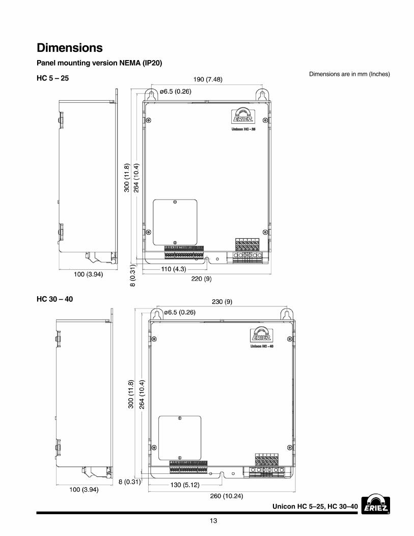
Dimensions (IP 20) HxWxD 300 x 220 x 100 mm (12 x 9 x 4 inch)
300 x 260 x 100 mm (12 x 10.25 x 4 inch)
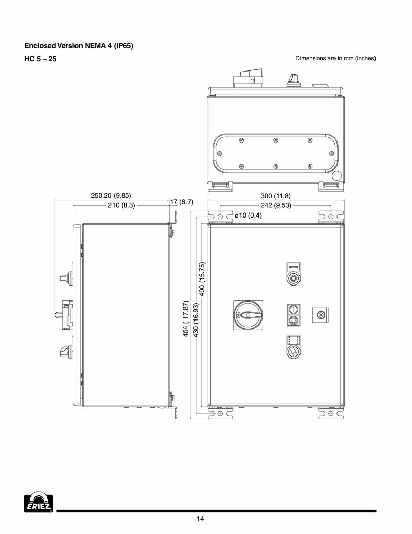
Dimensions (IP 65) HxWxD 400 x 354 x 268 mm (15.75 x 14 x 10.6 inch)
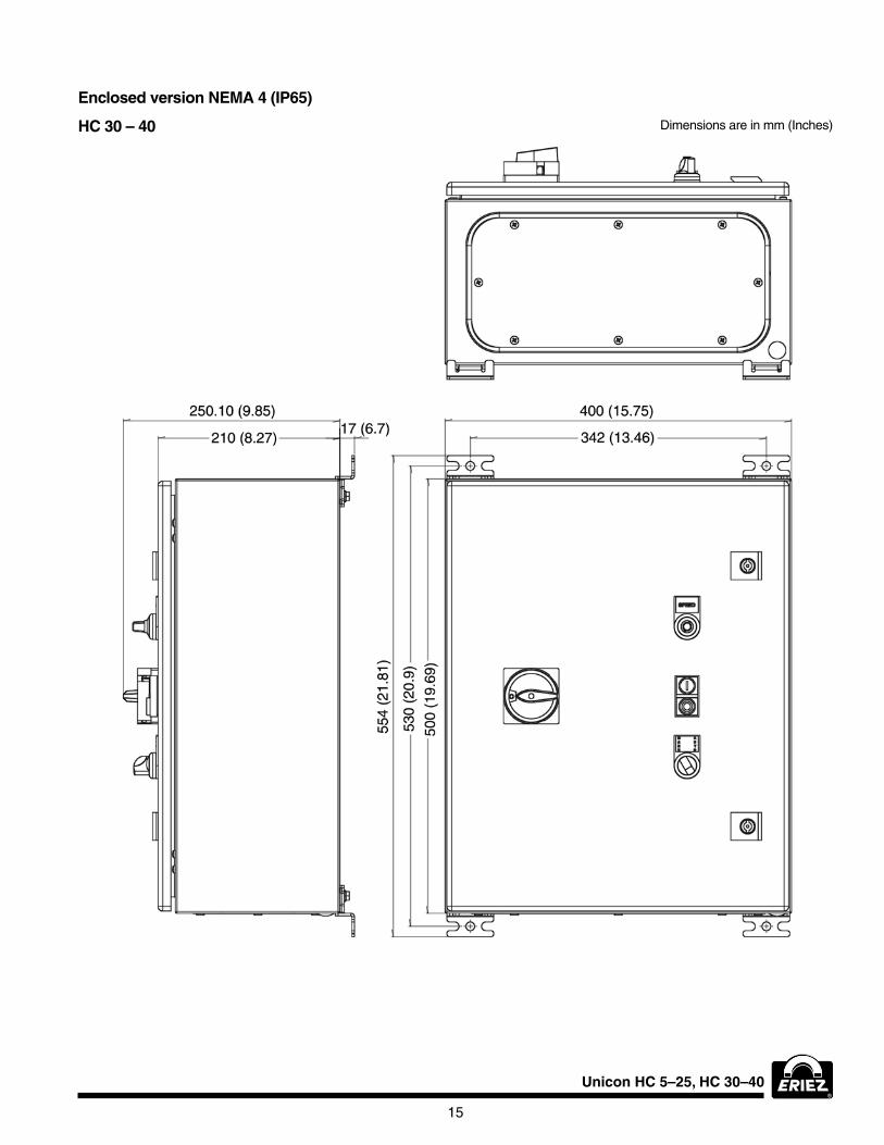
500 x 454 x 268 mm (19.7 x 18 x 10.6 inch)
Weight IP 20 / NEMA 1 3.8 kg (8.4 lb) 4.2 kg (9.25 lb)
Weight IP 65 / NEMA 4 14 kg (31 lb) 17.5 kg (38.5 lb)
1. Depend on input voltage and feeder power
2. Depend on input voltage
3. Depend on mains frequency
6
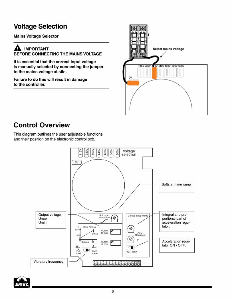
Voltage Selection
IMPORTANTBEFORE CONNECTING THE MAINS VOLTAGE
It is essential that the correct input voltage is manually selected by connecting the jumper to the mains voltage at site.
Failure to do this will result in damage to the controller.
Mains Voltage Selector
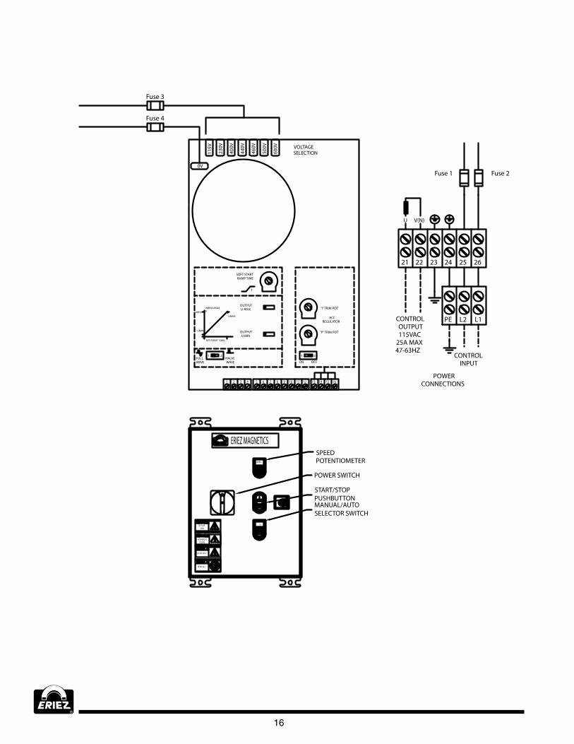
Control OverviewThis diagram outlines the user adjustable functions and their position on the electronic control pcb.
Unicon HC 5–25, HC 30–40
7
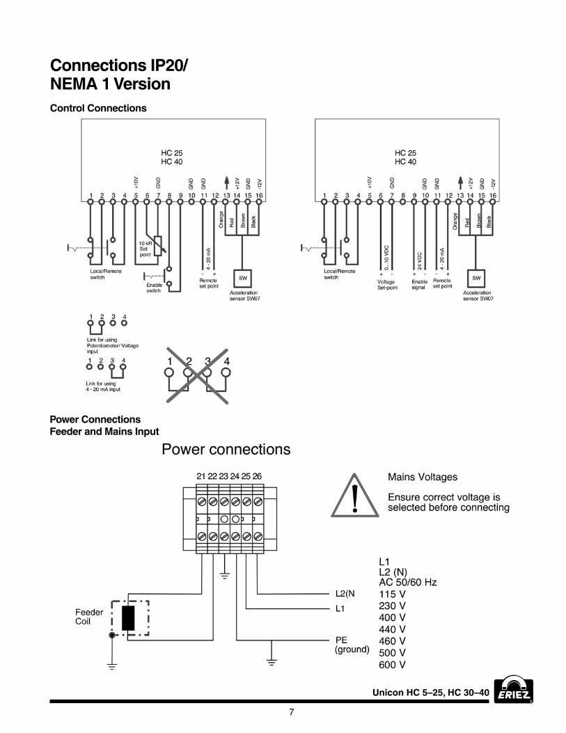
Control Connections
Connections IP20/ NEMA 1 Version
Power ConnectionsFeeder and Mains Input
8
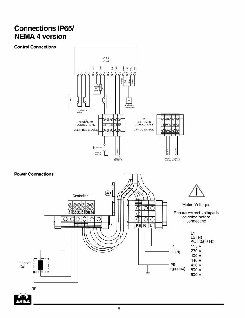
Control Connections
Connections IP65/ NEMA 4 version
Power Connections
Unicon HC 5–25, HC 30–40
9
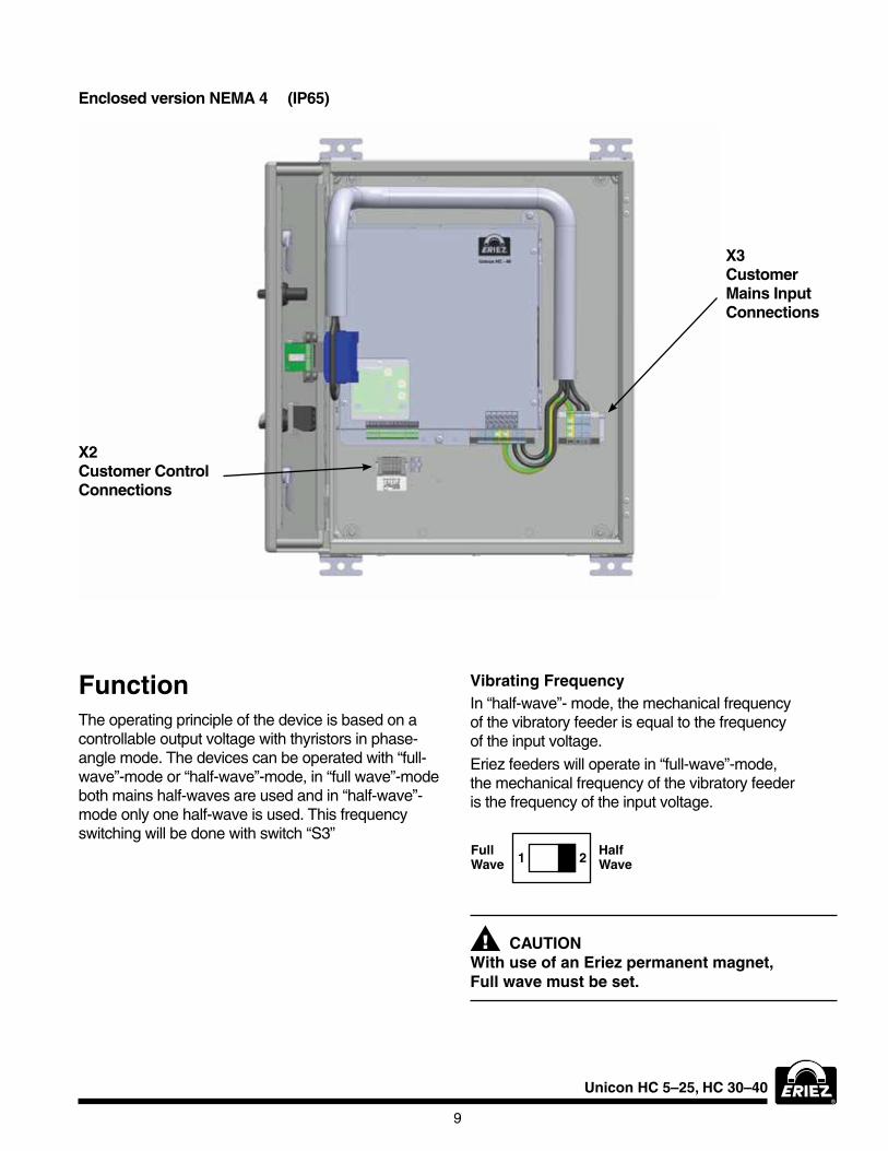
Enclosed version NEMA 4 (IP65)
X2 Customer Control Connections
X3 Customer Mains Input Connections
FunctionThe operating principle of the device is based on a controllable output voltage with thyristors in phase-angle mode. The devices can be operated with “full-wave”-mode or “half-wave”-mode, in “full wave”-mode both mains half-waves are used and in “half-wave”-mode only one half-wave is used. This frequency switching will be done with switch “S3”
Vibrating FrequencyIn “half-wave”- mode, the mechanical frequency of the vibratory feeder is equal to the frequency of the input voltage.Eriez feeders will operate in “full-wave”-mode, the mechanical frequency of the vibratory feeder is the frequency of the input voltage.
CAUTIONWith use of an Eriez permanent magnet, Full wave must be set.
1 2Half Wave
Full Wave
10
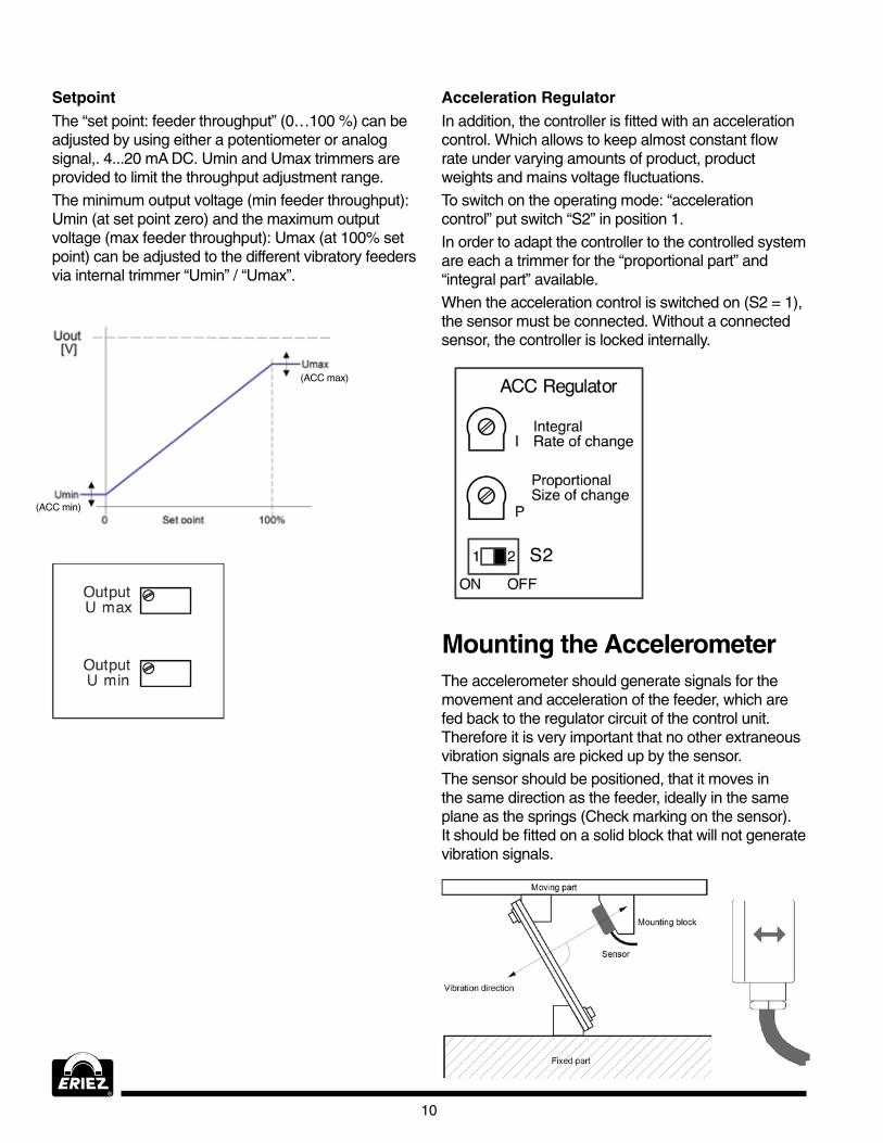
SetpointThe “set point: feeder throughput” (0…100 %) can be adjusted by using either a potentiometer or analog signal,. 4...20 mA DC. Umin and Umax trimmers are provided to limit the throughput adjustment range.The minimum output voltage (min feeder throughput): Umin (at set point zero) and the maximum output voltage (max feeder throughput): Umax (at 100% set point) can be adjusted to the different vibratory feeders via internal trimmer “Umin” / “Umax”.
Acceleration RegulatorIn addition, the controller is fitted with an acceleration control. which allows to keep almost constant flow rate under varying amounts of product, product weights and mains voltage fluctuations.To switch on the operating mode: “acceleration control” put switch “S2” in position 1.In order to adapt the controller to the controlled system are each a trimmer for the “proportional part” and “integral part” available.when the acceleration control is switched on (S2 = 1), the sensor must be connected. without a connected sensor, the controller is locked internally.
(ACC min)
(ACC max)
The accelerometer should generate signals for the movement and acceleration of the feeder, which are fed back to the regulator circuit of the control unit. Therefore it is very important that no other extraneous vibration signals are picked up by the sensor.The sensor should be positioned, that it moves in the same direction as the feeder, ideally in the same plane as the springs (Check marking on the sensor). It should be fitted on a solid block that will not generate vibration signals.
Mounting the Accelerometer
Unicon HC 5–25, HC 30–40
11
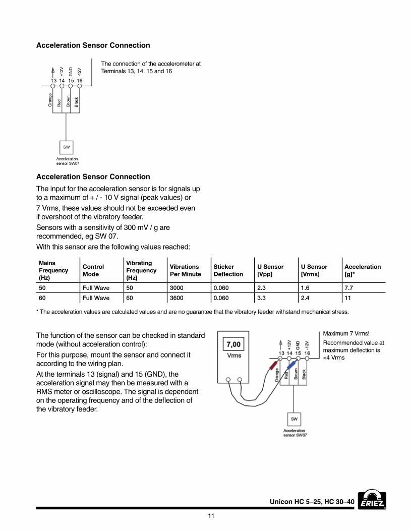
Acceleration Sensor Connection
The connection of the accelerometer at Terminals 13, 14, 15 and 16
Acceleration Sensor Connection
The input for the acceleration sensor is for signals up to a maximum of + / - 10 V signal (peak values) or 7 Vrms, these values should not be exceeded even if overshoot of the vibratory feeder.Sensors with a sensitivity of 300 mV / g are recommended, eg Sw 07.with this sensor are the following values reached:
Mains Frequency (Hz)
Control Mode
Vibrating Frequency (Hz)
Vibrations Per Minute
Sticker Deflection
U Sensor [Vpp]
U Sensor [Vrms]
Acceleration [g]*
50 Full Wave 50 3000 0.060 2.3 1.6 7.7
60 Full Wave 60 3600 0.060 3.3 2.4 11
* The acceleration values are calculated values and are no guarantee that the vibratory feeder withstand mechanical stress.
The function of the sensor can be checked in standard mode (without acceleration control):for this purpose, mount the sensor and connect it according to the wiring plan.At the terminals 13 (signal) and 15 (GND), the acceleration signal may then be measured with a RMS meter or oscilloscope. The signal is dependent on the operating frequency and of the deflection of the vibratory feeder.
Maximum 7 Vrms!
Recommended value at maximum deflection is <4 Vrms
12
Step 1: Without Acceleration Control 1. Selecting and setting of the operating voltage of the control unit for the given supply voltage and (bridge plug).
2. Mounting of the acceleration sensor on the moving part of the vibratory feeder in consideration of the moving direction.
3. Ensure that the supply cables are free of voltage!! Then connect the controller and acceleration sensor according to the wiring plan.
4. Set the vibratory frequency of the feeder at the controller with S3 (full wave / half wave).
5. Turn acceleration control off: S2 = 2.
6. Switch on the supply voltage
7. Take unit into operation. Adjust with the trimmers Umin / Umax: the minimum output voltage at set point “zero”, then set the maximum output voltage at set point 100%.
8. Adjust the soft start as required.
9. Measure the voltage at the sensor input, the voltage should be at 0 - 100% set point in the range 0 ... 4 Vrms. 7 Vrms must not be exceeded!
Startup of a Vibratory Feeder with Acceleration Control
Step 2: Activate Acceleration Control: 10. Set set point to “zero”
11. Turn acceleration control on: S2 =1, Trimmer I in position: (12 clock) Trimmer P in position: 9 clock Trimmer Umin in position: left stop (7 clock)
12. Increase set point, the vibratory feeder is now working in a control loop, the maximum throughput can be adjusted with the trimmer Umax (limited).
A minimum throughput at set point zero can be set with trimmer Umin.
13. Adjust the regulation speed and regulation stability with the trimmer P and I. The settings depend on the particular vibratory feeder. Presetting as described under point 11, should be optimized first with the trimmer P then with the trimmer I.
Unicon HC 5–25, HC 30–40
13
Panel mounting version NEMA (IP20)
Dimensions
HC 5 – 25Dimensions are in mm (Inches)
HC 30 – 40
14
HC 5 – 25
Enclosed Version NEMA 4 (IP65)
Dimensions are in mm (Inches)
Unicon HC 5–25, HC 30–40
15
HC 30 – 40
Enclosed version NEMA 4 (IP65)
Dimensions are in mm (Inches)
16
MANU
21 3 4 65 7 8 109 11 12 1413 15 16
1 2
ON OFF
"P" TRIM POT
ACCREGULATOR
1 2
SOFT STARTRAMP TIME
T
OUTPUTU MAX
OUTPUTU MIN
FULLWAVE
HALVEWAVE
SET POINT 100%
VOLTAGESELECTION11
5V
0V
230V
400V
440V
460V
500V
600V
100%UMAX
UMIN/UMAXV
UMIN
0
AUTO
SPEED
ON
READ ALL
WARNINGWARNINGWARNINGWARNINGWARNINGWARNINGWARNINGWARNINGWARNINGWARNINGWARNINGWARNINGWARNINGWARNINGWARNINGWARNINGWARNING
DANGERDANGERDANGERDANGERDANGERDANGERDANGERDANGERDANGERDANGERDANGERDANGERDANGER
HAZARDOUSVOLTAGE
WARNINGWARNINGWARNINGWARNINGWARNINGWARNINGWARNINGWARNINGWARNINGWARNINGWARNINGWARNINGWARNINGWARNINGWARNINGWARNINGWARNING
ELECTRIC SHOCK
ERIEZ MAGNETICS
ARC FLASHDANGERDANGERDANGERDANGERDANGERDANGERDANGERDANGERDANGERDANGERDANGERDANGERDANGER
SHOCK
SPEEDPOTENTIOMETER
POWER SWITCH
START/STOP PUSHBUTTONMANUAL/AUTOSELECTOR SWITCH
2221 23 24 25 26
U V(N)
CONTROLOUTPUT115VAC
25A MAX 47-63HZ
Fuse 1
Fuse 3
Fuse 4
"I" TRIM POT
POWER CONNECTIONS
CONTROLINPUT
PE L2 L1
Fuse 2
Unicon HC 5–25, HC 30–40
17
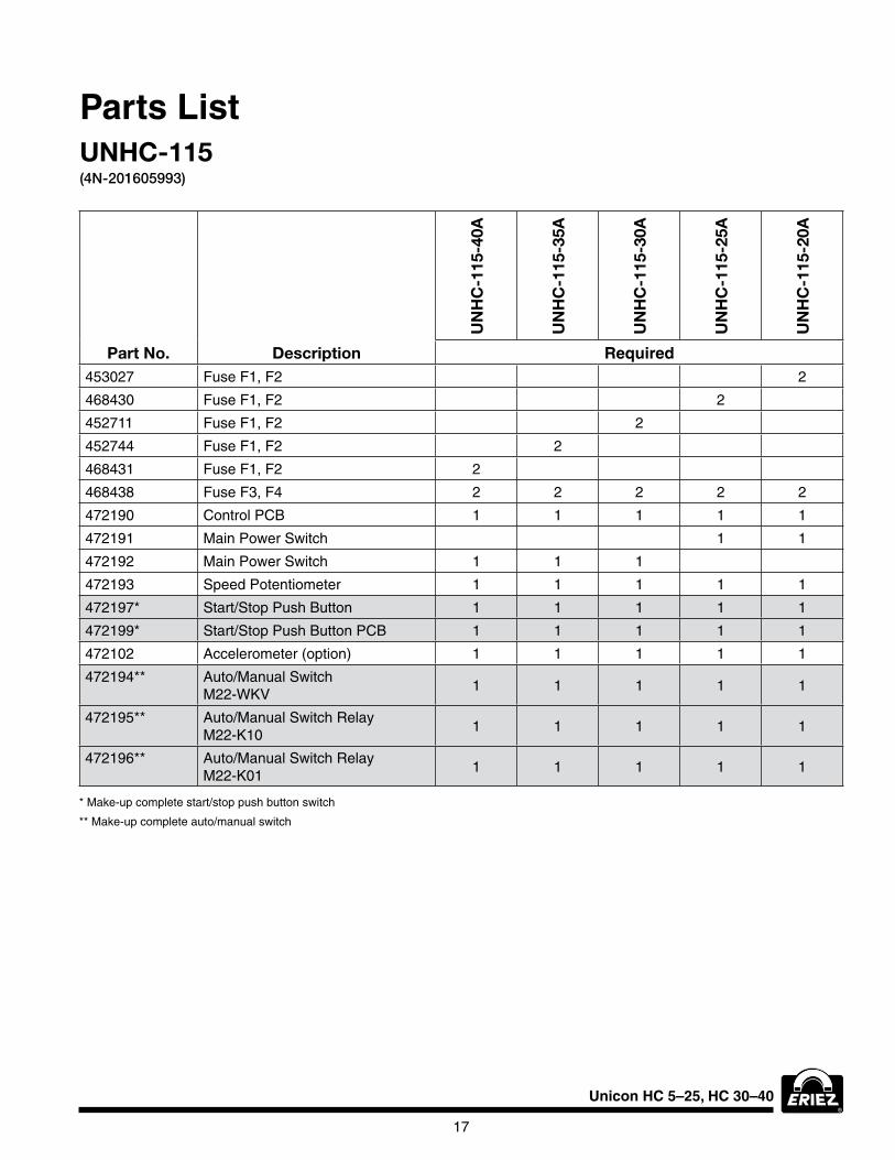
Part No. Description
UN
HC
-115
-40A
UN
HC
-115
-35A
UN
HC
-115
-30A
UN
HC
-115
-25A
UN
HC
-115
-20A
Required453027 fuse f1, f2 2
468430 fuse f1, f2 2
452711 fuse f1, f2 2
452744 fuse f1, f2 2
468431 fuse f1, f2 2
468438 fuse f3, f4 2 2 2 2 2
472190 Control PCb 1 1 1 1 1
472191 Main Power Switch 1 1
472192 Main Power Switch 1 1 1
472193 Speed Potentiometer 1 1 1 1 1
472197* Start/Stop Push button 1 1 1 1 1
472199* Start/Stop Push button PCb 1 1 1 1 1
472102 Accelerometer (option) 1 1 1 1 1
472194** Auto/Manual Switch M22-wKV
1 1 1 1 1
472195** Auto/Manual Switch Relay M22-K10
1 1 1 1 1
472196** Auto/Manual Switch Relay M22-K01
1 1 1 1 1
Parts ListUNHC-115(4N-201605993)
* Make-up complete start/stop push button switch
** Make-up complete auto/manual switch
18
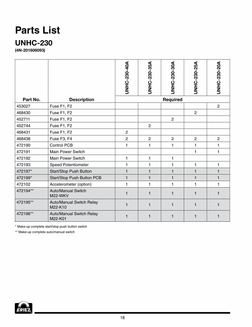
Part No. Description
UN
HC
-230
-40A
UN
HC
-230
-35A
UN
HC
-230
-30A
UN
HC
-230
-25A
UN
HC
-230
-20A
Required453027 fuse f1, f2 2
468430 fuse f1, f2 2
452711 fuse f1, f2 2
452744 fuse f1, f2 2
468431 fuse f1, f2 2
468438 fuse f3, f4 2 2 2 2 2
472190 Control PCb 1 1 1 1 1
472191 Main Power Switch 1 1
472192 Main Power Switch 1 1 1
472193 Speed Potentiometer 1 1 1 1 1
472197* Start/Stop Push button 1 1 1 1 1
472199* Start/Stop Push button PCb 1 1 1 1 1
472102 Accelerometer (option) 1 1 1 1 1
472194** Auto/Manual Switch M22-wKV
1 1 1 1 1
472195** Auto/Manual Switch Relay M22-K10
1 1 1 1 1
472196** Auto/Manual Switch Relay M22-K01
1 1 1 1 1
Parts ListUNHC-230(4N-201606093)
* Make-up complete start/stop push button switch
** Make-up complete auto/manual switch

Unicon HC 5–25, HC 30–40
19
Part No. Description
UN
HC
-380
-40A
UN
HC
-380
-35A
UN
HC
-380
-30A
UN
HC
-380
-25A
UN
HC
-380
-20A
UN
HC
-380
-15A
UN
HC
-380
-10A
UN
HC
-380
-5A
Required452709 fuse f1, f2 2
452710 fuse f1, f2 2
472071 fuse f1, f2 2
453027 fuse f1, f2 2
468430 fuse f1, f2 2
452711 fuse f1, f2 2
452744 fuse f1, f2 2
468431 fuse f1, f2 2
468438 fuse f3, f4 2 2 2 2 2 2 2 2
472190 Control PCb 1 1 1 1 1 1 1 1
472191 Main Power Switch 1 1 1 1 1
472192 Main Power Switch 1 1 1
472193 Speed Potentiometer 1 1 1 1 1
472197* Start/Stop Push button 1 1 1 1 1
472199* Start/Stop Push button PCb 1 1 1 1 1
472102 Accelerometer (option) 1 1 1 1 1
472194** Auto/Manual Switch M22-wKV
1 1 1 1 1
472195** Auto/Manual Switch Relay M22-K10
1 1 1 1 1
472196** Auto/Manual Switch Relay M22-K01
1 1 1 1 1
Parts ListUNHC-380(4N-201606108)
* Make-up complete start/stop push button switch
** Make-up complete auto/manual switch

Unicon HC 5–25, HC 30–40
20
Part No. Description
UN
HC
-460
-40A
UN
HC
-460
-35A
UN
HC
-460
-30A
UN
HC
-460
-25A
UN
HC
-460
-20A
UN
HC
-460
-15A
UN
HC
-460
-10A
UN
HC
-460
-5A
Required452709 fuse f1, f2 2
452710 fuse f1, f2 2
472071 fuse f1, f2 2
453027 fuse f1, f2 2
468430 fuse f1, f2 2
452711 fuse f1, f2 2
452744 fuse f1, f2 2
468431 fuse f1, f2 2
468438 fuse f3, f4 2 2 2 2 2 2 2 2
472190 Control PCb 1 1 1 1 1 1 1 1
472191 Main Power Switch 1 1 1 1 1
472192 Main Power Switch 1 1 1
472193 Speed Potentiometer 1 1 1 1 1
472197* Start/Stop Push button 1 1 1 1 1
472199* Start/Stop Push button PCb 1 1 1 1 1
472102 Accelerometer (option) 1 1 1 1 1
472194** Auto/Manual Switch M22-wKV
1 1 1 1 1
472195** Auto/Manual Switch Relay M22-K10
1 1 1 1 1
472196** Auto/Manual Switch Relay M22-K01
1 1 1 1 1
Parts ListUNHC-460(4N-201606159)
* Make-up complete start/stop push button switch
** Make-up complete auto/manual switch
Unicon HC 5–25, HC 30–40
21
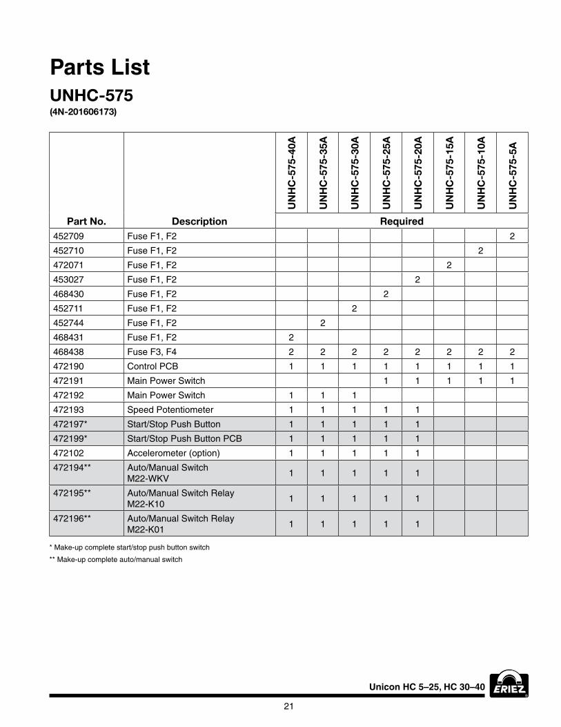
Part No. Description
UN
HC
-575
-40A
UN
HC
-575
-35A
UN
HC
-575
-30A
UN
HC
-575
-25A
UN
HC
-575
-20A
UN
HC
-575
-15A
UN
HC
-575
-10A
UN
HC
-575
-5A
Required452709 fuse f1, f2 2
452710 fuse f1, f2 2
472071 fuse f1, f2 2
453027 fuse f1, f2 2
468430 fuse f1, f2 2
452711 fuse f1, f2 2
452744 fuse f1, f2 2
468431 fuse f1, f2 2
468438 fuse f3, f4 2 2 2 2 2 2 2 2
472190 Control PCb 1 1 1 1 1 1 1 1
472191 Main Power Switch 1 1 1 1 1
472192 Main Power Switch 1 1 1
472193 Speed Potentiometer 1 1 1 1 1
472197* Start/Stop Push button 1 1 1 1 1
472199* Start/Stop Push button PCb 1 1 1 1 1
472102 Accelerometer (option) 1 1 1 1 1
472194** Auto/Manual Switch M22-wKV
1 1 1 1 1
472195** Auto/Manual Switch Relay M22-K10
1 1 1 1 1
472196** Auto/Manual Switch Relay M22-K01
1 1 1 1 1
Parts ListUNHC-575(4N-201606173)
* Make-up complete start/stop push button switch
** Make-up complete auto/manual switch
22
©2016 Eriez Magnetics All Rights Reserved
World Authority in Separation Technologies Headquarters: 2200 Asbury Road, Erie, PA 16506-1402 U.S.A. Telephone: 814-835-6000 • 800-345-4946 • Fax: 814-838-4960 • International Fax: 814-833-3348 Web Site: http://www.eriez.com e-mail: [email protected]
Manufacturing Facilities: AUSTRALIA • BRAZIL • CANADA • CHINA • INDIA • JAPAN • MEXICO • SOUTH AFRICA • UNITED KINGDOM • UNITED STATES
916-AHA-web ERIEZ MANUFACTURING CO ©2016 PRINTED IN USA
Eriez and Eriez Magnetics are registered trademarks of Eriez Manufacturing Co, Erie, PA
Agency ApprovalsCE ComplianceThe standard Unicon HC controls, enclosed and chassis mount, are CE compliant under the Low voltage and EC Electromagnetic Compatibility directives and are also RoHS compliant.
UL/CSA CertificationThe standard Unicon HC controls, enclosed and chassis mount, are UL and CSA certified for the U.S. and Canadian markets.