Embed Size (px)
Citation preview

SAFETY WARNINGOnly qualified personnel should install and service the equipment. The installation, starting up, and servicing of heating, ventilating, and air-conditioning equipment can be hazardous and requires specific knowledge and training. Improperly installed, adjusted or altered equipment by an unqualified person could result in death or serious injury. When working on the equipment, observe all precautions in the literature and on the tags, stickers, and labels that are attached to the equipment.
Rental Services Desiccant Dehumidification Units
June 2012 SRV-SVX04A-EN
Installation, Operation
and Maintenance

© 2012 Trane All rights reserved SRV-SVX04A-EN
Warnings, Cautions and Notices
Warnings, Cautions and Notices. Note that warnings, cautions and notices appear at appropriate intervals throughout this manual. Warnings are provide to alert installing contractors to potential hazards that could result in death or personal injury. Cautions are designed to alert personnel to hazardous situations that could result in personal injury, while notices indicate a situation that could result in equipment or property-damage-only accidents.
Your personal safety and the proper operation of this machine depend upon the strict observance of these precautions.
Read this manual thoroughly before operating or servicing this unit.
ImportantEnvironmental Concerns!
Scientific research has shown that certain man-made chemicals can affect the earth’s naturally occurring stratospheric ozone layer when released to the atmosphere. In particular, several of the identified chemicals that may affect the ozone layer are refrigerants that contain Chlorine, Fluorine and Carbon (CFCs) and those containing Hydrogen, Chlorine, Fluorine and Carbon (HCFCs). Not all refrigerants containing these compounds have the same potential impact to the environment. Trane advocates the responsible handling of all refrigerants-including industry replacements for CFCs such as HCFCs and HFCs.
Responsible Refrigerant Practices!
Trane believes that responsible refrigerant practices are important to the environment, our customers, and the air conditioning industry. All technicians who handle refrigerants must be certified. The Federal Clean Air Act (Section 608) sets forth the requirements for handling, reclaiming, recovering and recycling of certain refrigerants and the equipment that is used in these service procedures. In addition, some states or municipalities may have additional requirements that
must also be adhered to for responsible management of refrigerants. Know the applicable laws and follow them.
ATTENTION: Warnings, Cautions and Notices appear at appropriate sections throughout this literature. Read these carefully:
WARNINGIndicates a potentially hazardous situation which, if not avoided, could result in death or serious injury.
CAUTIONsIndicates a potentially hazardous situation which, if not avoided, could result in minor or moderate injury. It could also be used to alert against unsafe practices.
NOTICE: Indicates a situation that could result in equipment or property-damage only
WARNING
Proper Field Wiring and Grounding Required!
All field wiring MUST be performed by qualified personnel. Improperly installed and grounded field wiring poses FIRE and ELECTROCUTION hazards. To avoid these hazards, you MUST follow requirements for field wiring installation and grounding as described in NEC and your local/state electrical codes. Failure to follow code could result in death or serious injury.
WARNING
Personal Protective Equipment (PPE) Required!
Installing/servicing this unit could result in exposure to electrical, mechanical and chemical hazards.
• Before installing/servicing this unit, technicians
MUST put on all Personal Protective Equipment (PPE)
recommended for the work being undertaken.
ALWAYS refer to appropriate MSDS sheets and
OSHA guidelines for proper PPE.
• When working with or around hazardous chemicals,
ALWAYS refer to the appropriate MSDS sheets and
OSHA guidelines for information on allowable
personal exposure levels, proper respiratory
protection and handling recommendations.
• If there is a risk of arc or flash, technicians MUST put
on all Personal Protective Equipment (PPE) in
accordance with NFPA 70E or other country-specific
requirements for arc flash protection, PRIOR to
servicing the unit.
Failure to follow recommendations could result in death or serious injury.

SRV-SVX04A-EN 3
Table of Contents
Desiccant Dehumidification Unit Overview. 4Introduction . . . . . . . . . . . . . . . . . . . . . . . . . 4
Units Affected . . . . . . . . . . . . . . . . . . . . . . . 4
General Information . . . . . . . . . . . . . . . . . . 4
Unit Specifications . . . . . . . . . . . . . . . . . . . 5
Weights and Dimensions . . . . . . . . . . . . . . 5
Rigging Guidelines . . . . . . . . . . . . . . . . . . . . 6
Electrical Information . . . . . . . . . . . . . . . . . . 7
Unit Controls and Sequence of Operation. . 8
Fan Curve . . . . . . . . . . . . . . . . . . . . . . . . . . . 12
Wiring Diagrams . . . . . . . . . . . . . . . . . . . . . 13
Installation/Start-up Guidelines . . . . . . . . . 18Installation . . . . . . . . . . . . . . . . . . . . . . . . . 18
Start-up Guidelines . . . . . . . . . . . . . . . . . . 18
Shut Down Guidelines . . . . . . . . . . . . . . . 18
Maintenance Guidelines . . . . . . . . . . . . . . 18

Desiccant Dehumidification Unit Overview
Introduction
This Installation, Operation and Maintenance (IOM) manual covers the desiccant dehumidification units (DHU) available to rent from Trane Rental Services for temporary dehumidification solutions. This includes DHU technical information, start-up information and unit maintenance. The information contained in this manual is provided to ensure the safe installation and operation of the equipment and its surroundings.
The information provided in this IOM is to be used as a reference for each DHU to aid in determining unit size, power requirements, or lifting requirements. If additional information regarding a particular unit is required, please contact Trane Rental Services.
Contact Trane Rental Services Marketing for availability of equipment (including ancillary items: electrical cable, flexible duct, etc.) prior to securing rental equipment. Equipment is available on a first-come, first-serve basis, but can be reserved with a signed rental agreement.
Call Rental Services 24/7 at 1-800-755-5115 for specific questions.
Units Affected
RSDH0012F0XX –Desiccant Dehumidification Unit (DHU) with post cooling coil
Note: Where XX represents the unique inventory number.
General Information
The Trane Rental Services DHUs are highly efficient at providing clean, dehumidified air with minimal electrical power required. The DHUs can be used in free blow or ducted applications. Each unit has a single horizontal supply air connection and a single return air connection and is equipped with a post-cooling coil to aid in reducing leaving air temperatures when required. When used in free blow applications, ducting on the front of the unit must be removed. Flexible duct is available upon request.
1 Unit can be provided with reducer to provide either 2.5 inch or 4 inch grooved water connection to allow connection to our flexible water hose accessories.
Table 1.
Model RSDH0012
Manufacturer Munters™
Airflow Orientation Horizontal
Nominal Airflow 4,750 cfm
Blower RPM 3500
Max Static Discharge Pressure
1.70 in. ESP
Post-cooling Coil Water Connection(s)1
Type Flanged
Size 3 inches
Supply Air Connection(s)
Type Round
Quantity 1
Size 17.75 inches
Return Air Connection(s)
Type Round
Quantity 1
Size 17.75 inches
Reactivation Air Connection (s)
None (Free Blow)
Pre Filter Type 30% efficient
Quantity and Dimensions
(2) 12 in x 24 in(2) 24 in x 24 in
Inlet Delta P 0.21 in. WC
Final Delta P 0.42 in. WC
4 SRV-SVX04A-EN

Desiccant Dehumidification Unit Overview
Unit Specifications
Weights and Dimensions
Table 3.
Table 2.
Dehumidifier
Process Air Reactivation Air
Desiccant Type SCFM
Moisture Removal (lb/hr)
WheelP (in WC)
Unit P (in WC)
SCFMWheelP (in WC)
Unit P (in WC)
Energy Type
Input kW
SiGel 4750 102 1.82 2.12 1050 1.63 3.00 Electric 84
Fans
Fan Data Performance
LocationSize Rotation Motor HP RPM SCFM
TSP (in WC)
Sys Loss (in WC)
ESP (in WC)
Supply 15 CW 10 3500 4750 7.04 5.34 1.70 3
React 12-1/4-7 CW 3 3450 1050 4.50 3.00 1.50
Post Cooling Coil
Airside Values Coil Dimensions Fluidside values
Type SCFM Load MBH P (in WC) Face ft2 Rows FPI Flow (gpm) P (ft)
Post Cool 4750 366 1.58 10 10 12 57 24.5
Length Width Height Weight
15 ft 2 in 6 ft 2 in 6 ft 5 in 4,175 lbs
SRV-SVX04A-EN 5

Rigging Guidelines
The DHUs are equipped with fork pockets on two sides and lifting rings along the base of the unit.
Figure 1.
WARNING
Heavy Objects!
Ensure that all the lifting equipment used is properly rated for the weight of the unit being lifted. Each of the cables (chains or slings), hooks, and shackles used to lift the unit must be capable of supporting the entire weight of the unit. Refer to Table 3 for unit weight. Lifting cables (chains or slings) may not be of the same length. Adjust as necessary for even unit lift. Other lifting arrangements could cause equipment or property damage. Failure to follow instructions above or properly lift unit could result in death or serious injury.
6 SRV-SVX04A-EN

Electrical Information
The DHUs have connections to allow for use with our available 2/0 electrical cable. Below is a list of electrical data for these units. If additional information is needed, please contact Trane Rental Services.
Table 4.
Model RSDH0012
Fused Disconnect? Yes
Unit Power 460V, 3-phase
Unit MCA 154.1 A
Unit MOP 175 A
Supply Motor FLA 11.6 A
Reactivation Motor FLA 3.6 A
SRV-SVX04A-EN 7
Unit Controls and Sequence of Operation
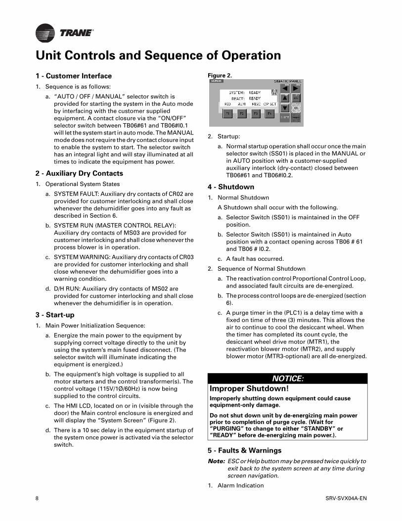
1 - Customer Interface
1. Sequence is as follows:
a. “AUTO / OFF / MANUAL” selector switch is provided for starting the system in the Auto mode by interfacing with the customer supplied equipment. A contact closure via the “ON/OFF” selector switch between TB06#61 and TB06#I0.1 will let the system start in auto mode. The MANUAL mode does not require the dry contact closure input to enable the system to start. The selector switch has an integral light and will stay illuminated at all times to indicate the equipment has power.
2 - Auxiliary Dry Contacts
1. Operational System States
a. SYSTEM FAULT: Auxiliary dry contacts of CR02 are provided for customer interlocking and shall close whenever the dehumidifier goes into any fault as described in Section 6.
b. SYSTEM RUN (MASTER CONTROL RELAY): Auxiliary dry contacts of MS03 are provided for customer interlocking and shall close whenever the process blower is in operation.
c. SYSTEM WARNING: Auxiliary dry contacts of CR03 are provided for customer interlocking and shall close whenever the dehumidifier goes into a warning condition.
d. D/H RUN: Auxiliary dry contacts of MS02 are provided for customer interlocking and shall close whenever the dehumidifier is in operation.
3 - Start-up
1. Main Power Initialization Sequence:
a. Energize the main power to the equipment by supplying correct voltage directly to the unit by using the system’s main fused disconnect. (The selector switch will illuminate indicating the equipment is energized.)
b. The equipment’s high voltage is supplied to all motor starters and the control transformer(s). The control voltage (115V/1Ø/60Hz) is now being supplied to the control circuits.
c. The HMI LCD, located on or in (visible through the door) the Main control enclosure is energized and will display the “System Screen” (Figure 2).
d. There is a 10 sec delay in the equipment startup of the system once power is activated via the selector switch.
Figure 2.
2. Startup:
a. Normal startup operation shall occur once the main selector switch (SS01) is placed in the MANUAL or in AUTO position with a customer-supplied auxiliary interlock (dry-contact) closed between TB06#61 and TB06#I0.2.
4 - Shutdown
1. Normal Shutdown
A Shutdown shall occur with the following.
a. Selector Switch (SS01) is maintained in the OFF position.
b. Selector Switch (SS01) is maintained in Auto position with a contact opening across TB06 # 61 and TB06 # I0.2.
c. A fault has occurred.
2. Sequence of Normal Shutdown
a. The reactivation control Proportional Control Loop, and associated fault circuits are de-energized.
b. The process control loops are de-energized (section 6).
c. A purge timer in the (PLC1) is a delay time with a fixed on time of three (3) minutes. This allows the air to continue to cool the desiccant wheel. When the timer has completed its count cycle, the desiccant wheel drive motor (MTR1), the reactivation blower motor (MTR2), and supply blower motor (MTR3-optional) are all de-energized.
5 - Faults & Warnings
Note: ESC or Help button may be pressed twice quickly to exit back to the system screen at any time during screen navigation.
1. Alarm Indication
NOTICE:
Improper Shutdown!
Improperly shutting down equipment could cause equipment-only damage.
Do not shut down unit by de-energizing main power prior to completion of purge cycle. (Wait for “PURGING” to change to either “STANDBY” or “READY” before de-energizing main power.).
8 SRV-SVX04A-EN

Unit Controls and Sequence of Operation
a. Fault and warning indication is seen in two possible manners on the equipment’s control enclosure. The HMI display and fault warning lights. The HMI will display the blinking triangle with exclamation point and the fault message on the Alarm screen (Figure 3).
b. A fault results in the Red Light (LT02) remaining illuminated constantly.
Figure 3.
2. List of System and DH Faults
a. FAULT - D/H WHEEL MOTOR STARTER PROTECTOR TRIPPED
i. If the desiccant drive motor starter/protector (MSP1) trips the system is faulted.
ii. The system will go into the shutdown sequence as described in Section 4, and the system auxiliary dry contacts close in sequence (described in Section 2), also process blower (optional) will purge.
iii. The dehumidifier will be held in the 'Fault' condition by (PLC1). To restart the dehumidifier clear the alarm pressing the acknowledge ACK on the HMI, reset the overload, and go to the ALARM screen and press the F4 RESET key this resets the PLC. To restart the system, the selector switch (SS01) must be moved to the “OFF” position, then move (SS01) back to the “AUTO” or “MANUAL” position.
b. FAULT - REACTIVATION MOTOR STARTER PROTECTOR TRIPPED
i. If the reactivation blower motor starter/protector (MSP2) trips the system is faulted.
ii. The dehumidifier goes into the shutdown sequence, as described in Section 4, and the system auxiliary dry contacts sequence as described in Section 2 The dehumidifier will be held in the 'Fault' condition by (PLC1). To restart the dehumidifier clear the alarm pressing the acknowledge ACK on the HMI, reset the overload, and go to the ALARM screen and press the F4 RESET key this resets the PLC. To restart the system, the selector switch (SS01) must be moved to the “OFF” position, then move (SS01) back to the “AUTO” or “MANUAL” position.
c. FAULT - SUPPLY BLOWER MOTOR STARTER PROTECTOR TRIPPED/ VFD FAULT (optional)
i. If the supply blower motor starter/protector (MSP3) trips or the customer-supplied variable frequency drive (VFD) goes into a Fault, the system is faulted.
ii. The system will go into the shutdown sequence (described in Section 4), and the system auxiliary dry contacts close in sequence (described in Section 2).
iii. The dehumidifier will be held in the 'Fault' condition by (PLC1). To restart the dehumidifier clear the alarm pressing the acknowledge ACK on the HMI, reset the overload, and go to the ALARM screen and press the F4 RESET key this resets the PLC. To restart the system, the selector switch (SS01) must be moved to the “OFF” position, then move (SS01) back to the “AUTO” or “MANUAL” position.
d. FAULT - DEHUMIDIFIER WHEEL ROTATION
i. Limit switch (LS01) is wired normally closed, and is located inside the dehumidifier wheel compartment next to desiccant wheel. As the wheel turns, a cam fastened to the wheel housing opens this limit switch.
ii. If limit switch (LS01) is not opened once every 600 seconds, a timer in (PLC1) times out the system is faulted.
iii. The system will go into the shutdown sequence (described in Section 4), and the system auxiliary dry contacts close in sequence (described in Section 2).
iv. The dehumidifier will be held in the 'Fault' condition by (PLC1). To restart the dehumidifier clear the alarm pressing the acknowledge ACK on the HMI, reset the overload, and go to the ALARM screen and press the F4 RESET key this resets the PLC. To restart the system, the selector switch (SS01) must be moved to the “OFF” position, then move (SS01) back to the “AUTO” or “MANUAL” position.
e. FAULT – REACTIVATION ELECTRIC HEATER OVERTEMPERATURE
i. Temperature switch (TS01) is located in the reactivation Electric Heater and is furnished to detect extreme temperature level or heat buildup.
ii. Temperature switch (TS01) is located in the reactivation “Heated To” duct and is furnished to detect extreme temperature level or heat buildup.
iii. The system will go into the shutdown sequence (described in Section 4), and the system auxiliary dry contacts close in sequence (described in Section 2).
SRV-SVX04A-EN 9
Unit Controls and Sequence of Operation
iv. The dehumidifier will be held in the 'Fault' condition by (PLC1). To restart the dehumidifier clear the alarm pressing the acknowledge ACK on the HMI, reset the overload, and go to the ALARM screen and press the F4 RESET key this resets the PLC. To restart the system, the selector switch (SS01) must be moved to the “OFF” position, then move (SS01) back to the “AUTO” or “MANUAL” position.
6 - List of System and DH Warnings
1. WARNING – REACTIVATION LOW TEMP
a. LOW TEMP (Reactivation Low Temperature Fault Set point). The adjustment range is 90.0 to 110.0. The parameter corresponds to the value of the set point in engineering units (Typical set point = 110°F).
7 - Proportional Control Loops/ Dh Interlocks
1. Reactivation Heat Energy Control
a. The Reactivation Electric Heater Solid State Relays accepts a 0-10V modulating signal from the logic controller to control the Reactivation Inlet air temperature, as sensed by the reactivation air inlet temperature transmitter (TC01 The Reactivation Inlet temperature set point will be varied based on the Reactivation outlet control PID loop to maintain maximum required Reactivation inlet temperatures over a wide range of DH load conditions.
b. When the reactivation outlet PID loop output is 0% the Reactivation inlet set point will be 200°F. When the reactivation outlet PID loop output is 100% the Reactivation Inlet set point will be 325°F.
8 - Human Machine Interface Control (Op73
Simatic Panel)
1. Screen descriptions, navigation and security:
Note: Other visual options are password protected for FACTORY USE ONLY.
a. System Screen This screen is the first screen that comes up when power is applied to the equipment (Figure 2). The System screen displays the equipment’s operational status along with separate indication for the Reactivation air stream. The System screen also acts as the navigation portal for all of the screens configured in the system. All navigation references in this section assume the operator starts on the System screen. At any time during navigation, the ESC button on the Simatic Panel may be pressed twice to return to the System screen.
Equipment Status Indications
“SYSTEM” displays the modes of operation of the process as listed below:
READY = The system is ready to run and there are no faults and the interlocks are made.
RUNNING = The system is running and process control loops are running if they are enabled.
FAULTED = The system has faulted.
PURGING = The system is going thru a shutdown sequence and is purging.
“REACT” displays the modes of operation of the dehumidifier as listed below:
READY = The DH is ready to run and there are no faults and the interlocks are made.
RUNNING = The DH is running and process control loops are running if they are enabled.
FAULTED = The DH has faulted.
PURGING = The DH is going thru a shutdown sequence and is purging.
STANDBY = The System is Running and the DH is stopped because there is no call for dehumidification (full bypass).
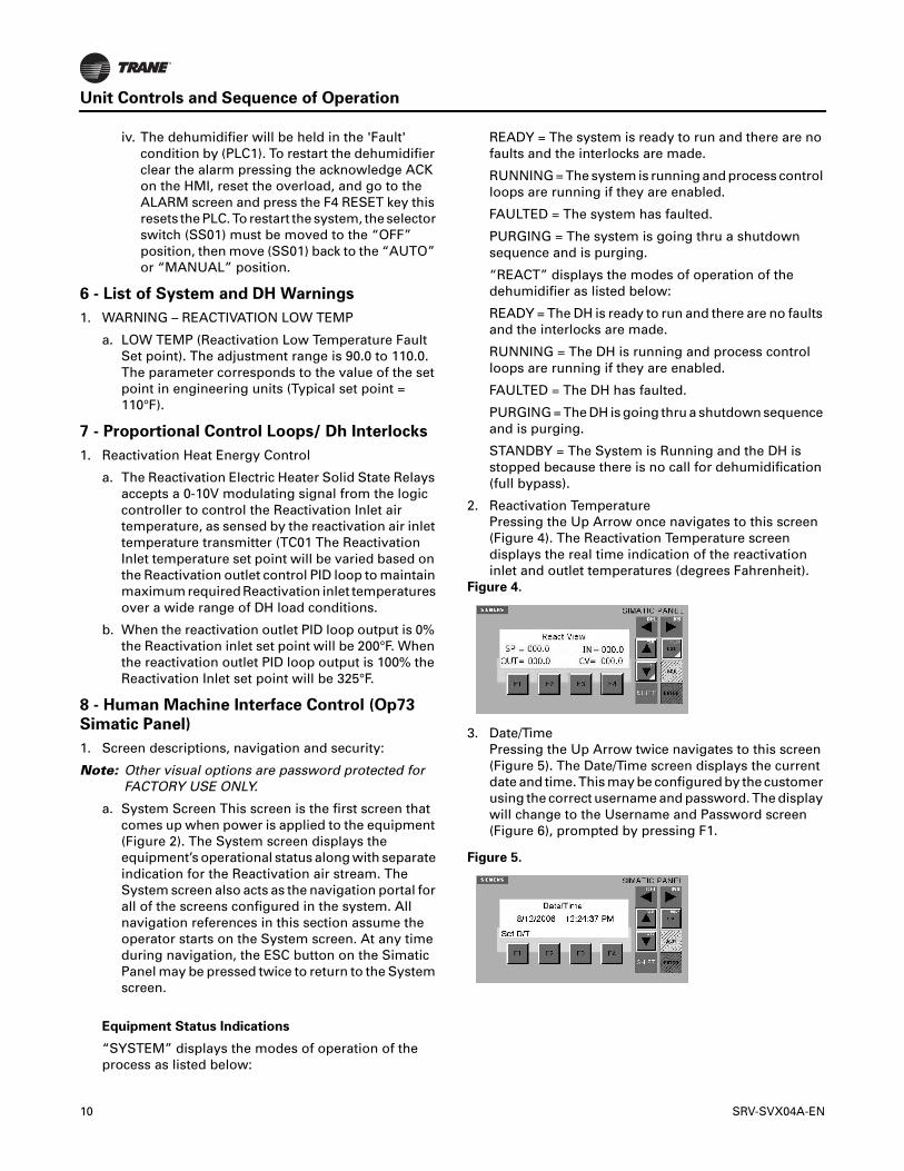
2. Reactivation Temperature Pressing the Up Arrow once navigates to this screen (Figure 4). The Reactivation Temperature screen displays the real time indication of the reactivation inlet and outlet temperatures (degrees Fahrenheit).
Figure 4.
3. Date/Time Pressing the Up Arrow twice navigates to this screen (Figure 5). The Date/Time screen displays the current date and time. This may be configured by the customer using the correct username and password. The display will change to the Username and Password screen (Figure 6), prompted by pressing F1.
Figure 5.
10 SRV-SVX04A-EN

Unit Controls and Sequence of Operation
Figure 6.
4. Username & Password The operator will be prompted by the appearance of the password screen (Figure 6) on occasions where secure parameters are attempting to be accessed. (Contact Rental Services Technical Support if a password is required.). Then ENTER button will reverse highlight the character for editing. Use the arrows buttons as necessary to select the desired characters. Once the last character has been located press enter, NOT ANY ARROW, to proceed to the password window. Press ENTER again to allow editing again for the password. Once the last character has been located press enter, NOT ANY ARROW, the “OK” shall display a dotted box within, press ENTER to accept and the screen will return to make the selection without security restriction.
5. Run Time Meter Pressing the Down Arrow once navigates to this screen (Figure 7). The Run Time Meter screen displays the amount of time in hours that the equipment has been in operation. There is an indication for DH displaying the amount of time dehumidification has been requested and in operation. These values, shown in hours, may vary dependant on the equipment’s configuration.
Figure 7.
6. Control Group Selection 1* Pressing F1 (PID) will navigate to this screen (Figure 8). The OP73 Display may prompt the operator for Username and Password (figure 9); this must be entered to proceed (section 7.7). See Section 834 for information regarding Username and Password. The Control Group Selection 1 screen displays the various system loops available on the equipment.
a. Alarms Pressing F2 (ALM) will navigate to this screen (Figure 8). The Alarm screen displays the Faults and Warnings the system encountered during operation. The triangle with exclamation point will indicate to the operator when an alarm condition
exists. The current alarm message may be cleared without clearing the history by pressing the ACK button.The Alarm Screen displays and records information on triggered alarms. Each time an alarm is triggered, it is added to the Alarm History list Figure 9, and the last alarm shall be displayed.
Figure 8.
Figure 9.
b. F4 RESET The operator must press the F4 button to reset a fault in the PLC; this will clear all system faults and enable the equipment to be restarted by cycling the selector switch. The selector switch may also be used as the system reset by turning it to the off position and return it to the auto or manual position. The acknowledge button (ACK) must be pressed to clear the message and alarm symbol indication. The system screen will display READY after a fault has been reset.
c. F1 CLEAR History The alarm history (Figure 9.) can be viewed by pressing the down arrow first and both up and down arrows to scroll the alarms stored. Clearing the alarm history press F1. It will prompt for the Username and Password, upon entering the correct characters the operator has the ability to clear the history.
SRV-SVX04A-EN 11

Fan Curve
Figure 10.
12 SRV-SVX04A-EN

SRV-SVX04A-EN 13
Wiring Diagrams
Figure 11.
Figure 12.

Wiring Diagrams
Figure 13.
Figure 14.
14 SRV-SVX04A-EN

Wiring Diagrams
Figure 15.
Figure 16.
SRV-SVX04A-EN 15

Wiring Diagrams
Figure 17.
Figure 18.
16 SRV-SVX04A-EN

Wiring Diagrams
Figure 19.
Figure 20.
SRV-SVX04A-EN 17

Installation/Start-up Guidelines
Installation
[ ] Confirm unit is properly leveled.
[ ] Verify air inlet and outlet are clear of any debris or obstructions.
[ ] Connect power cable from unit to the power source and confirm that the wires are properly phased, connected and locked securely to panel.
[ ] For ducted applications:
• Install the supply and return air ducts on the duct adapters on the front of the unit. Ensure as straight a run of duct as possible.
[ ] For free blow applications:
• No duct installation required.
Start-up Guidelines
[ ] Verify that the unit disconnect is in the “OFF” position on the unit.
[ ] Energize the source power to the DHU.
[ ] Switch the unit disconnect to the “ON” position to supply power to the unit.
Figure 21. Main Unit Disconnect
[ ] Consult the “Unit Controls and Sequence of Operation” section on page 8 of this document for unit operation.
[ ] Close all covers (local and remote panels) and secure.
Shut Down Guidelines
[ ] Consult the “Shutdown Sequence” section on page 8 of this document for unit shutdown procedure.
Maintenance Guidelines
The motor and blower bearings are permanently lubricated and require no maintenance. The desiccant wheel is belt driven. The drive belt should be examined periodically for wear and correct tension.
Each unit is provided with disposable filters that are installed in the return air section. The filter access panel must be removed to gain access to the filters. Check filters periodically to verify that they are clean.
WARNING
Hazardous Voltage!
Disconnect all electric power, including remote disconnects, before servicing. Follow proper lockout/tagout procedures to ensure the power cannot be inadvertently energized. Failure to disconnect power before servicing could result in death or serious injury.
NOTICE:
Proper Airflow!
The reactivation air from the unit could be in excess of 180°F. Do not position unit where reactivation outlet air could come into contact with sensitive materials and cause equipment and property damage.
18 SRV-SVX04A-EN


Trane optimizes the performance of homes and buildings around the world. A business of Ingersoll Rand, the leader in creating and sustaining safe, comfortable and energy efficient environments, Trane offers a broad portfolio of advanced controls and HVAC systems, comprehensive building services, and parts.For more information, visit www.Trane.com.
Trane has a policy of continuous product and product data improvement and reserves the right to change design and specifications without notice.
We are committed to using environmentally
conscious print practices that reduce waste.
© 2012 Trane All rights reserved
SRV-SVX04A-EN 19 June 2012
Supersedes New