Embed Size (px)
Citation preview

INSTALLATION, OPERATION & MAINTENANCE MANUAL
ACMO-AVK CONTROL VALVE
SERIES 879 - M200 - 879/BB1X99PRESSURE SUSTAINING VALVERev. 00 - 20200520
ACMO-AVK_IOM_879-M200_2020COPYRIGHT©AVKGROUP - ACMO - www.acmosrl.com

Index
1. Manufacturer identification
2. General health and safety measures
3. Receiving and storage 3.1 Product identification 3.2 Packing 3.3 Transport and storing
4. Testing valves
5. Warranty
6. Disposal and recycling
7. Series 879 overview 7.1 Valve components description 7.2 Valve dimensions 7.3 Diagrams 7.4 Hydraulic specifications
8. Principle of operation
9. Installation
10. Hydraulic circuit
11. Static tests once installed
12. Commissioning
13. Maintenance
14. Recommended spare parts
15. Troubleshooting
16. ACM200 pilot 16.1 Pilot: Components and dimensions 16.2 Pilot: Troubleshooting 16.3 Pilot: Recommended spare parts
The designs, materials and specifications shown are subject to change without notice. This is due to the continuous development of our product programme.
Unauthorized use is forbidden.
ACMO-AVK | IOM Manuals
ACMO-AVK_IOM_879-M200_00-202005202
ACMO-AVK CONTROL VALVE SERIES 879879/BB1X99 - M200 PRESSURE SUSTAINING VALVE
03
03
04040404
05
05
05
0606070809
09
09
10
11
11
12
12
13
14141515

1. Manufacturer identification
2. General health and safety measures
AC.MO S.r.l. Headquarters Street: Via Tommaso da Modena, 28 Z.I. - 31056 RONCADE (TV) ITALY Tel: +390422840220 r.a. Fax: +390422840923 e-mail: [email protected]
• Read the IOM manual before using the valve. Comply with the manual at all times.
• The IOM manual must be available in the workplace.
• Non–compliance with the general safety measures can seriously damage human health and valve functioning. AC.MO S.r.l. will not assume any responsibility or liability for consequential damage due to the non-compliance with these instructions.
• The valve can be used for drinking water and clean service water. Other uses are prohibited because they can alter the valve safety.
• Never use the valve in plants where the pressure is higher than the one indicated.
• Only qualified staff can install the valve. Unqualified or underage staff cannot perform the installation. Always use protective equipment such as safety boots, safety helmets, goggles, protective gloves, etc... Personnel involved in the installation or maintenance of valves should be constantly alert to possible damages caused by an improper handling of the valve.
• Before performing any work on the valve, depressurize the pipeline section and ensure it is free of hazards.
• Unauthorized, unintentional and unexpected actuation, as well as any hazardous movement caused by stored energy (pressurized air, water under pressure) must be prevented.
• When a valve needs to be dismantled from a pipeline, water may emerge from the pipeline or the valve. The pipeline must be emptied completely before the valve is dismantled. It is strictly prohibited to disinstall any component when the system is under pressure (working) or when there is any fluid inside.
• Statutory and local provisions as well as the safety and accident prevention regulations must be observed and complied with at all times.
• For equipment that must be monitored, the relevant laws and regulations such as the Industrial Code, Accident Prevention Regulations, etc. must be complied with. In addition to this, local accident prevention regulations apply.
PLEASE NOTE: That if the valve closes too rapidly it can generate a water hammer in the pipes.
For product improvement purposes, AC.MO S.r.l. reserves the right to change the data in this manual at any time and without notice. Unauthorized use of data is forbidden. Please contact us for up-to-date information.
Thank you for purchasing our product. We kindly invite you to read carefully the operating instructions and safety rules in this manual, which is part of the product.
ACMO-AVK | IOM Manuals
ACMO-AVK_IOM_879-M200_00-20200520 3
ACMO-AVK CONTROL VALVE SERIES 879879/BB1X99 - M200 PRESSURE SUSTAINING VALVE
The designs, materials and specifications shown are subject to change without notice. This is due to the continuous development of our product programme.
Unauthorized use is forbidden.

+ -
PRESSURE REDUCINGMod. ACV100A
Range 1.0 - 2.0 barCalibration 8.5 bar
Year:rr 2020
www.acmosrl.com
RR
EN1074-5 / EN558 SERIES 1GJS/AISI304/EPDM
WATER 70C
s/n 00/000/000
MADE IN ITATT LYLLYEAR: 2020
DN 50 PN 10/16
879/BB0X99
www.acmosrl.com
R
DN50....100 DN125....150 DN200....600
3.1 Product identification
• The valve is labeled on the body with ACMO/AVK logo and model identification number of the valve.
• The pilot is labeled with ACMO/AVK logo, the model identification number and the setting parameters.
3.2 Packing
The valves are generally delivered in europallets, alternatively, in dedicated high thickness paper boxes. In both cases, they are fastened to the pallet using bolts and covered with a polyethylene heat-shrinking film. The package depends on the valve dimensions and on the actuator and/or hydraulic circuit that may be installed on the valve. The package depends on the valve dimensions and on the hydraulic circuit dimensions.
Packing examples:
3.3 Transport and storing
WARNING: Please carefully inspect the unit for damages or discrepancies with the order upon arrival and report a claim immediately before unloading the goods.
Lifting the valve improperly may damage it. Lift the valves using slings (ISO 4878), otherwise, if present on one valve, using the specific eyebolts.Make sure the slings do not interfere with circuit components. Don’t lift up the valves using the position indicator or the accessories and pipes installed on the valve.Please make sure the lifting tools (lift truck, slings, cranes, hooks, etc.) are adequate for the weight. Before you move the valve it is necessary to consult the weight table at page 7. Make sure their coefficient of safety is equal or higher than the coefficient allowed by law.
If the valve is stored for a middle or long term, it is necessary to:• Lay the valve in a horizontal and firm position, in order to avoid capsizings which could
damage things or people.• Store the valves in an area protected from weather conditions especially from sunlight, which
could damage the coats and the gaskets.
The designs, materials and specifications shown are subject to change without notice. This is due to the continuous development of our product programme.
Unauthorized use is forbidden.
ACMO-AVK | IOM Manuals
ACMO-AVK_IOM_879-M200_00-202005204
ACMO-AVK CONTROL VALVE SERIES 879879/BB1X99 - M200 PRESSURE SUSTAINING VALVE
3. Receiving and storage

AC.MO S.r.l. guarantees its products for the supplier or the client for a 12 month consecutive period since the delivery date to the final client. The warranty coverage period will correspond to the date on the final client’s delivery note. Product faults and damages must be pointed out within 8 days since their identification.
The warranty covers all the parts manufactured/provided by AC.MO S.r.l..
Warranty does not cover normal wear damages.
The warranty does not apply to:• Valves equipped with tools and accessories, unauthorized by AC.MO S.r.l..• Valves damaged by misuse, accidents or other chances, negligence, eccess load etc..• Valves damaged by lack of maintenance.• Valves equipped with non-original spare parts.• Valves modified without authorisation.
Even though AC.MO S.r.l. valves are designed and built to be extremely long lasting, at the end of their life cycle they must be removed and replaced. Dismantle the valve, separate its components to dispose them of and recycle them (e.g., metal parts must be separated from plastic parts etc.).
WARNING: Always respect the directives on waste collection, disposal and recycling.
Carefully observe all steps listed in National Laws on waste disposal and recycling.
All valves AC.MO S.r.l. designs are tested and controlled before leaving our premises. The test (inspection certificate) is available on request.
4. Testing valves
5. Warranty
6. Disposal and recycling
ACMO-AVK | IOM Manuals
ACMO-AVK_IOM_879-M200_00-20200520 5
ACMO-AVK CONTROL VALVE SERIES 879879/BB1X99 - M200 PRESSURE SUSTAINING VALVE
The designs, materials and specifications shown are subject to change without notice. This is due to the continuous development of our product programme.
Unauthorized use is forbidden.

ITEM DESCRIPTION MATERIALS STANDARDS
1 BODY DUCTILE IRON EN GJS-500-7 EN 1563
2 O-RING RUBBER EPDM EN 681-1
3 O-RING RUBBER EPDM EN 681-1
4 PLUG SEALING RUBBER EPDM EN 681-1
5 HEX NUT STAINLESS STEEL A2 EN ISO 3506-1
6 WASHER STAINLESS STEEL AISI304 EN 10088-3
7 BOLTS STAINLESS STEEL A2 EN ISO 3506-1
8 DIAPHRAGM RUBBER EPDM EN 681-1
9 SPRING STAINLESS STEEL AISI304 EN 10088-3
10 FLAT SEAL RUBBER EPDM EN 681-1
11 FLAT SEAL RUBBER EPDM EN 681-1
12 COVER DUCTILE IRON EN GJS-500-7 EN 1563
13 HEX NUT STAINLESS STEEL A2 EN ISO 3506-1
14 DIAPHRAGM SUPPORT DUCTILE IRON EN GJS-500-7 EN 1563
15 OBTURATOR DUCTILE IRON EN GJS-500-7 EN 1563
16 REGULATING PLUG STAINLESS STEEL AISI304 EN 10088-3
17 SEAT STAINLESS STEEL AISI304 EN 10088-3
18 STEM STAINLESS STEEL AISI304 EN 10088-3
7. Series 879 overview
7.1 Valve components description
15
16
17
18
1312
14
2
3
4
1
78 10
11
96
5
The designs, materials and specifications shown are subject to change without notice. This is due to the continuous development of our product programme.
Unauthorized use is forbidden.
ACMO-AVK | IOM Manuals
ACMO-AVK_IOM_879-M200_00-202005206
ACMO-AVK CONTROL VALVE SERIES 879879/BB1X99 - M200 PRESSURE SUSTAINING VALVE
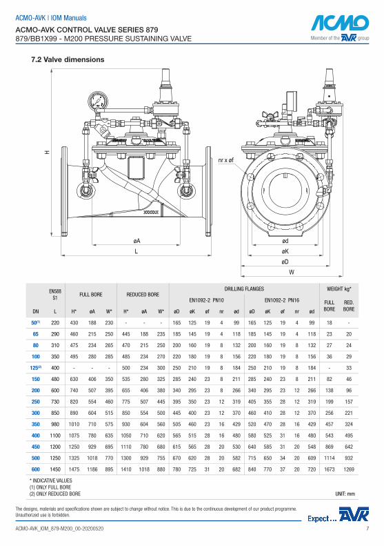
7.2 Valve dimensions
øA
H
øDW
øKLød
nr x øf
EN588S1
FULL BORE REDUCED BOREDRILLING FLANGES WEIGHT kg*
EN1092-2 PN10 EN1092-2 PN16 FULL BORE
RED. BOREDN L H* øA W* H* øA W* øD øK øf nr ød øD øK øf nr ød
50(1) 220 430 188 230 - - - 165 125 19 4 99 165 125 19 4 99 18 -
65 290 460 215 250 445 188 235 185 145 19 4 118 185 145 19 4 118 23 20
80 310 475 234 265 470 215 250 200 160 19 8 132 200 160 19 8 132 27 24
100 350 495 280 285 485 234 270 220 180 19 8 156 220 180 19 8 156 36 29
125(2) 400 - - - 500 234 300 250 210 19 8 184 250 210 19 8 184 - 33
150 480 630 406 350 535 280 325 285 240 23 8 211 285 240 23 8 211 82 46
200 600 740 507 395 655 406 380 340 295 23 8 266 340 295 23 12 266 138 96
250 730 820 554 460 775 507 445 395 350 23 12 319 405 355 28 12 319 199 157
300 850 890 604 515 850 554 500 445 400 23 12 370 460 410 28 12 370 256 221
350 980 1010 710 575 930 604 560 505 460 23 16 429 520 470 28 16 429 457 324
400 1100 1075 780 635 1050 710 620 565 515 28 16 480 580 525 31 16 480 543 495
450 1200 1250 929 695 1110 780 680 615 565 28 20 530 640 585 31 20 548 869 642
500 1250 1325 1018 770 1300 929 755 670 620 28 20 582 715 650 34 20 609 1114 932
600 1450 1475 1186 895 1410 1018 880 780 725 31 20 682 840 770 37 20 720 1673 1269
* INDICATIVE VALUES(1) ONLY FULL BORE(2) ONLY REDUCED BORE UNIT: mm
ACMO-AVK | IOM Manuals
ACMO-AVK_IOM_879-M200_00-20200520 7
ACMO-AVK CONTROL VALVE SERIES 879879/BB1X99 - M200 PRESSURE SUSTAINING VALVE
The designs, materials and specifications shown are subject to change without notice. This is due to the continuous development of our product programme.
Unauthorized use is forbidden.

The diagram shows indicatively the two operating areas of the reducer, according to the applicable upstream and downstream pressures. AREA A: continuous working conditions. No cavitation risk.AREA B: intermitting working conditions. Possible cavitation risk.
Continuous working conditions in the B ZONE can damage rapidly the internal parts. Appropriate design precautions must be adopted if the valve works in this ZONE. Please, contact our Technical Department.
DIAGRAM FOR THE CAVITATION CHECK
Limit of use
Recommended fluid velocity upstream of the valve: Continuous service: 3,5 m/s Peak service: 5 m/s
Minimum necessary differential pressure: 0,2 bar.
Working temperature from -10°C to +80°C.
0 1 2 3 4 5 6 7 8 9 1 00
5
1 0
1 5
2 0
2 5
B
A
CAVITATION RISK
NO CAVITATION
DOWNSTREAM PRESSURE (bar)
UPST
REAM
PRE
SSUR
E (b
ar)
HEAD LOSS DIAGRAM
FLOW RATE (m3/h)
HEAD
LOSS
(bar
)
0.01
0.1
1.0
1 10 100 1000 10000
DN50
DN65
DN80
DN10
0
DN15
0
DN20
0DN
250
DN30
0
DN35
0
DN45
0DN
400
DN50
0DN
600
REDUCED BOREFULL BORE DN
65
DN80
DN10
0DN
125
DN15
0
DN20
0
DN25
0DN
300
DN35
0
DN45
0DN
400
DN50
0DN
600
7.3 Diagrams
The designs, materials and specifications shown are subject to change without notice. This is due to the continuous development of our product programme.
Unauthorized use is forbidden.
ACMO-AVK | IOM Manuals
ACMO-AVK_IOM_879-M200_00-202005208
ACMO-AVK CONTROL VALVE SERIES 879879/BB1X99 - M200 PRESSURE SUSTAINING VALVE

7.4. Hydraulic specifications
• Leave appropriate space to facilitate the assembling/dismantling and maintenance operations.
• Before the installation, wash the pipes properly to eliminate any residual. Not washing the pipes properly can compromise the valve functioning.
• Install a resilient seat gate valves upstream and downstream the valve in order to facilitate maintenance operations.
• Install the valve on the pipeline, checking the arrow printed on the valve must follow the water flow. Use the eyelet on the cover to lift or lower the valve.
• The valve should be installed in a horizontal position with the cover up; other positions are also possible but must be verified with our Technical Office.
• Make sure the valve position permits to easily dismantle the hydraulic circuit or its components.
• After the installation, check there are not damages to any joint, pipe or tools.
8. Principle of operation
9. Installation
DN - REDUCED BORE 65 80 100 125 150 200 250 300 350 400 450 500 600
Kv [m3/h] 53 83 119 135 202 435 734 990 1584 2221 2899 3865 4735
STROKE [mm] 16 18.5 23.2 23.2 25.2 44.5 53.8 64.3 74.9 89.2 100 113.3 125.1
DN - FULL BORE 50 65 80 100 150 200 250 300 350 400 450 500 600
Kv [m3/h] 44 76 116 175 400 710 947 1355 2174 2734 3757 4548 6539
STROKE [mm] 16 18.5 23.2 25.2 44.5 53.8 64.3 74.9 89.2 100 113.3 125.1 150
The pressure sustaining valve is an automatic control valve designed to sustain a minimum pressure upstream and/or to release excessive pressure downstream. The pilot valve detects the pressure upstream and determines the modulation of the principal valve that keeps the inlet pressure constant. The pilot valve is equipped with an adjusting screw to pre-select the desired pressure.When the principal valve (in line) functions as a sustaining valve, and the upstream pressure is lower than the calibrated pressure, the valve modulates to the closed position maintaining the pre-selected value independently of the pressure variation or of the water demand of the system. When the principal valve (in derivation) functions as a relief valve, and the upstream pressure is higher than the calibrated pressure, the principal valve modulates to the open position releasing the excessive pressure and maintaining the preselected value.
ACMO-AVK | IOM Manuals
ACMO-AVK_IOM_879-M200_00-20200520 9
ACMO-AVK CONTROL VALVE SERIES 879879/BB1X99 - M200 PRESSURE SUSTAINING VALVE
The designs, materials and specifications shown are subject to change without notice. This is due to the continuous development of our product programme.
Unauthorized use is forbidden.

ITEM DESCRIPTION MATERIALS
1 2-WAY BALL VALVE NICKEL BRASS
2 Y-STRAINER + CALIBRATED ORIFICE (3 mm) BRASS + S.S. AISI316
3 UNIDIRECTIONAL NEEDLE VALVE STAINLESS STEEL
4 2-WAY BALL VALVE NICKEL BRASS
5 PRESSURE SUSTAINIG PILOT type ACM200 STAINLESS STEEL
6 PRESSURE GAUGE STAINLESS STEEL
7 3-WAY BALL VALVE NICKEL BRASS
8 2-WAY BALL VALVE NICKEL BRASS
5
12
8
4
3
7
6
10. Hydraulic circuit
The designs, materials and specifications shown are subject to change without notice. This is due to the continuous development of our product programme.
Unauthorized use is forbidden.
ACMO-AVK | IOM Manuals
ACMO-AVK_IOM_879-M200_00-2020052010
ACMO-AVK CONTROL VALVE SERIES 879879/BB1X99 - M200 PRESSURE SUSTAINING VALVE

OPEN valve static test:
1. Close ball valves 1 - 4 - 8 to isolate the pilot control system. This prevents impurities from entering the control circuit.
2. Fully open the main valve by removing the cap on the cover or by loosening a junction or opening ball valve 4.
WARNING: Check this procedure does not cause any damage to the pipeline.
3. Check that the flanged junctions, pipe fittings, etc. do not leak.4. Reassemble the cap on the cover and/or tighten the junctions.
CLOSE valve static test:
1. Close the ball valve 8, located downstream of the pilot, and open ball valves 1 - 4.2. Release the air under the cover of the main valve loosening the junction situated in the highest
point of the cover. Tighten the junction. This will keep the valve shut when the pipeline is pressurized.
3. Check the cover does not leak, in case, tighten the fixing bolts.
WARNING: To calibrate the pressure sustaining valve a sufficient upstream pressure is needed. Start a pump or open upstream gate valves to reach the sufficient upstream pressure.
1. Close and open the ball valves as explained before to close the main valve.
2. The needle valve 3 has been calibrated in our factory. To reduce the opening speed of the hydraulic valve, turn needle valve 3 clock wise. Vice versa to increase it.
3. Turn the calibration screw, situated on the pilot valve 5, clock wise until it reaches the total blocking position. Open ball valve 8: the main valve will stay closed if the downstream pressure is lower than the maximum calibration pressure of the pilot.
4. How to regulate the pressure relief:4.1. Slowly, turn the pilot calibration screw 5 counter-clockwise until the main valve starts opening. Keep on turning the calibration screw slowly stopping at each half rotation to reach the equilibrium. Select the upstream pressure according to the pressure indicated on the pressure gauge 6. Tighten the lock nut on the regulator screw.4.2. To check the valve functioning, decrease the upstream pressure using other devices. The valve should close slightly keeping the upstream pressure constant.
11. Static tests once installed
12. Commissioning
ACMO-AVK | IOM Manuals
ACMO-AVK_IOM_879-M200_00-20200520 11
ACMO-AVK CONTROL VALVE SERIES 879879/BB1X99 - M200 PRESSURE SUSTAINING VALVE
The designs, materials and specifications shown are subject to change without notice. This is due to the continuous development of our product programme.
Unauthorized use is forbidden.

The quality of the material used to manufacture our valves and control circuits avoids abnormal wear of the internal components for many years. However, we recommend checking the valve as follows:
After 5 months operation:• Control and clean the strainer (if present) installed on the main pipeline and the strainer on the
pilot circuit of the valve.• If blocked, the strainer on the pilot circuit takes the main valve gradually out of order.
NOTE: Clean the strainer regularly following the specific timetable of the plant. This timetable cannot be predetermined but must be decided only when the valve is on duty.
After 12 months operation:• Control and clean the strainer (if present) installed on the main pipeline and the strainer on the
pilot circuit of the valve.• Remove the control circuit.• Remove the screws on the valve cover, remove the cover, and take out the obturator completely. • Check for any eventual damage of the rubber components, such as: the lip seals of the piston
and the seal gasket to schedule the maintenance intervention. • Assemble the obturator, the valve cover and tighten the bolts properly.• Put the valve back into service.
This kind of check allows scheduling the maintenance required by the valve, taking into account the real working conditions.
13. Maintenance
14. Recommended spare parts
The designs, materials and specifications shown are subject to change without notice. This is due to the continuous development of our product programme.
Unauthorized use is forbidden.
ACMO-AVK | IOM Manuals
ACMO-AVK_IOM_879-M200_00-2020052012
ACMO-AVK CONTROL VALVE SERIES 879879/BB1X99 - M200 PRESSURE SUSTAINING VALVE
ITEM(see page 6)
QTY DESCRIPTION MATERIALS
2-3 1 O-RING RUBBER EPDM
9 1 SPRING STAINLESS STEEL AISI304
8 1 DIAPHRAGM RUBBER EPDM

PROBLEM CAUSE SOLUTION
THE VALVE DOES NOT OPEN
Low inlet pressure. Check the pressure or apply a higher inlet pressure.
Pilot spring 5 is excessively compressed. Turn the pilot calibration screw 5 counter-clockwise until the valve opens.
Insufficient water demand. Check the water demand or make it increase.
Ball valves 4 – 8 are closed. Open ball valves 4 - 8.
THE VALVE DOES NOT CLOSE
Circuit strainer 2 is clogged. Clean the strainer 2.
Ball valves 1 - 4 closed. Open ball valves 1 - 4.
Pilot spring 5 is insufficiently compressed. Turn the pilot calibration screw 5clockwise until the valve closes.
Residues in the main valve. Remove and inspection the actuator.Inspection the disc gasket and the seat.
The main valve diaphragm leaks. Close the ball valve 1 - 4 - 8 and remove the plug from the cover. If the diaphragm continues leaking it must be substituted because it has been damaged.WARNING: The valve will open completely.
THE VALVE DOES NOT REGULATE
Swings. Slowly calibrate the needle valve 3 until the swings stop.
Air in the upper part of the valve. Loosen the cover connections, let the air escape and tighten the connections again.
PLEASE NOTE: While working, ball valves 1 - 4 - 8 must be OPEN. While cleaning the strainer 2 ball valves 1 - 4 - 8 must be CLOSE.
15. Troubleshooting
ACMO-AVK | IOM Manuals
ACMO-AVK_IOM_879-M200_00-20200520 13
ACMO-AVK CONTROL VALVE SERIES 879879/BB1X99 - M200 PRESSURE SUSTAINING VALVE
The designs, materials and specifications shown are subject to change without notice. This is due to the continuous development of our product programme.
Unauthorized use is forbidden.

TYPE PILOT RANGE (bar) SPRING COLOR
ACM200 A 1,0 - 5,0 RED
ACM200 B 2,0 - 15,0 BLACK
ACM200 C 2,5 -21,0 BLACK
ITEM DESCRIPTION MATERIALS STANDARDS
1 CAP ABS -
2ADJUSTING SCREW
STAINLESS STEEL AISI304
EN 10088-1
3 JAM NUTSTAINLESS STEEL A2
EN 10088-3
4SPRING GUIDE
STAINLESS STEEL AISI304
EN 10088-1
5 COVERSTAINLESS STEEL AISI304
EN 10088-1
6 SPRINGTEMPERED STEEL SiCrV
EN 10027
7 NUTSTAINLESS STEEL A2
EN 10088-3
8SPRING GUIDE
Mn-Steel+Ni Plated -
9FIXING HOLDER
STAINLESS STEEL AISI304
EN 10088-1
10 SCREWSTAINLESS STEEL A2
EN 10088-3
11 DIAPHRAGM EPDM+NYLON EN 681-1
12 PLATESTAINLESS STEEL AISI304
EN 10088-1
13 O-RING NBR EN 681-1
14INTERNAL BODY
STAINLESS STEEL AISI304
EN 10088-1
15 O-RING NBR EN 681-1
16 O-RING NBR EN 681-1
17 STEMSTAINLESS STEEL AISI304
EN 10088-1
18 SHUTTER AISI304 + EPDMEN 10088-1 + EN 681-1
19 BODYSTAINLESS STEEL AISI304
EN 10088-1
16. ACM200 pilot
16.1 Pilot: Components and dimensions
The designs, materials and specifications shown are subject to change without notice. This is due to the continuous development of our product programme.
Unauthorized use is forbidden.
1
2
3
456
789
10
11
1314
15161718
19
12
90
PT/N
PT 1/
2”17
7.5PT
/NPT
1/4”
ACMO-AVK | IOM Manuals
ACMO-AVK_IOM_879-M200_00-2020052014
ACMO-AVK CONTROL VALVE SERIES 879879/BB1X99 - M200 PRESSURE SUSTAINING VALVE

PROBLEM CAUSE SOLUTION
THE PILOT VALVE DOES NOT CLOSE TIGHT
Spring 6 is insufficiently compressed. Turn the pilot calibration screw 2clockwise.
Shutter seal gasket 18 is damaged. Substitute seal gasket 18.
THE COVER OF THE PILOT LEAKS
Diaphragm 11 is damaged. Substitute diaphragm 11.
ITEM QTY DESCRIPTION MATERIALS
6 1 SPRING TEMPERED STEEL SiCrV
11 1 DIAPHRAGM EPDM + NYLON
18 1 SHUTTER AISI304 + EPDM
16.2 Pilot: Troubleshooting
16.3 Pilot: Recommended spare parts
ACMO-AVK | IOM Manuals
ACMO-AVK_IOM_879-M200_00-20200520 15
ACMO-AVK CONTROL VALVE SERIES 879879/BB1X99 - M200 PRESSURE SUSTAINING VALVE
The designs, materials and specifications shown are subject to change without notice. This is due to the continuous development of our product programme.
Unauthorized use is forbidden.

Legal Office:00136 Roma - Italy - Via Franco Michelini Tocci, 93tel +39066628238 - fax [email protected]
Headquarters:31056 Roncade (TV) - Italy - Via T. da Modena, 28 - Z.I.
tel +390422840220 r.a. - fax [email protected]
www.acmosrl.com