Embed Size (px)
Citation preview

Providing indoor climate comfort
TELECOOL - THN
TELECOOL THN-IOM-0104-E
Installation, operating and maintenance

IOM / TELECOOL THN - 0104 - E Page 1
CONTENTS
GENERAL DESCRIPTION 2
BASIC COOLANT CIRCUIT ....................................................................................... 3
INSTALLATION WARNINGS ...................................................................................... 4
INSPECTION 5
TRANSPORT .............................................................................................................. 5
UNPACKING ............................................................................................................... 5
POSITIONING ............................................................................................................ 5
INSTALLATION 7
ELECTRICAL CONNECTIONS ................................................................................ 10
STARTING UP 11
PRELIMINARY CHECKS........................................................................................... 11
STARTING UP INSTRUCTIONS .............................................................................. 12
SETTING OPERATING PARAMETERS 15
GENERALITIES ........................................................................................................ 15
MAXIMUM PRESSURE SWITCH ............................................................................ 16
MINIMUM PRESSURE SWITCH.............................................................................. 16
ROUTINE MAINTENANCE AND CHECKS 17
WARNINGS .............................................................................................................. 17
GENERALITIES ........................................................................................................ 18
REPAIRING THE COOLING CIRCUIT ..................................................................... 20
TIGHTNESS TEST ................................................................................................... 21
HARD VACUUM AND DRYING OF COOLING CIRCUIT ......................................... 21
CHARGING WITH R407C REFRIGERANT ............................................................. 22
ENVIRONMENTAL PROTECTION ........................................................................... 22
TROUBLESHOOTING 23
TECHNICAL DATA 25
CONTENTS

Page 2 - IOM / TELECOOL THN - 0104 - E
GENERAL DESCRIPTION
Structure
All THN units have a galvanised sheet steel supporting base,and enclosing panels made galvanised sheet steel coated withepoxy polyester powder paint oven cured at 180°C (RALxxxx).The unit features an exclusive design which, combined with arational layout of components and extremely compactdimensions, lends it an attractive appearance.
Field of Application:
Model
Power supply
Minimum outdoortemperature TMaximum outdoortemperature TMinimum indoortemp./humidity conditionsMaximum indoor temp./humidity conditions
Storage conditions
Cooling circuit
The entire cooling circuit is built in the HiRef factory usingonly components of the finest quality brands and processesconforming to the specifications of Directive 97/23 for brazingand testing.
Compressors: only scroll-type compressors of leadinginternational manufacturers are used in the THN units.Today scroll compressors represent the best solutionin terms of reliability, efficiency and MTBF.
Cooling components:o Molecular mesh activated-alumina filter dryero Flow indicator with humidity indicator.
Indications are provided directly on the sightglass.
o Thermostatic valve with external equalizationand integrated MOP function.
o High and low pressure switcheso Schrader valves for checks and/or
maintenance
Electric control board: The electric control board isconstructed and wired in accordance with Directives73/23/EEC and 89/336/EEC and related standards.The board may be accessed through a door after themain switch has been put off. All the remote controlsuse 24 V signals powered by an insulating transformersituated on the electric control board.
NOTE: the mechanical safety devices such as the highpressure switch are of the kind that trigger directly; theirefficiency will not be affected by any faults occurring inthe microprocessor control circuit, in compliance with 97/23 PED.
Control microprocessor: the microprocessor built intothe unit allows the different operating parameters tobe controlled from a set of pushbuttons situated onthe electric control board;
o Switching on/off of compressor to maintain thetemperature set point T inside the shelter
o Alarm managementHigh / low pressureDirty filters alarmAir flow alarm
o Alarm signallingo Display of operating parameterso RS232, RS485 serial output management
(optional)o Phase sequence error [Not displayed by the
mP, but prevents the compressor from startingup]
[see microprocessor control manual for further details, alsoin relation to particular customer specifications]
GENERAL DESCRIPTION
THN “HiRef Telecom units” are air conditioners for low- andmedium-powered telephone exchanges. They are designedto be mounted inside shelter.THN air conditioners are direct expansion package units withan air-cooled condenser system. They are distinguished byan innovative air circulation system which significantlyenhances performance in all operating conditions.
THN THN THN045 056 073
230Vac+/-10%24 Vdc +/- 16% - 48 Vdc +/- 16%
- 20 °C
45 °C 45 °C 45 °C
19 °C - 30 % r.h.
35 °C - 50 % r.h.
-10 / 90 % r.h.+ 55 / 90 % r.h.
THN THN THN THN THN090 105 120 150 170
400Vac+/-10% /3/50 + N24 Vdc +/- 16% - 48 Vdc +/- 16%
- 20 °C
46 °C 45 °C 46 °C 46 °C 45 °C
19 °C - 30 % r.h.
35 °C - 50 % r.h.
-10 / 90 % r.h.+ 55 / 90 % r.h.
THN units are to be used within the operating limits stated in this manual; failure to comply with said limits willinvalidate the warranties provided in the contract of sale.

IOM / TELECOOL THN - 0104 - E Page 3
GENERAL DESCRIPTION
BASIC COOLING CIRCUIT
ENGLISH
1 COMPRESSOR2 CONDENSER3 THERMOSTATIC4 EVAPORATOR5 FILTER DRYER6 SIGHT GLASS7 LOW PRESSURE SWITCH8 HIGH PRESSURE SWITCH9 CONDENSING PRESSURE PROBE

Page 4 - IOM / TELECOOL THN - 0104 - E
INSTALLATION WARNINGS
GENERAL RULES
- When installing or servicing the unit, you must strictly follow the rules provided in this manual, comply with the directions onthe units themselves and take all such precautions as are necessary.
- The fluids under pressure in the cooling circuit and the presence of electrical components may cause hazardous situationsduring installation and maintenance work.
All work on the unit must be carried out by qualified personnel only, trained to do theirjob in accordance with current laws and regulations.
- Failure to comply with the rules provided in this manual or any modification made to the unit without prior authorisation willresult in the immediate invalidation of the warranty.
Warning: Before performing any kind of work on the unit, make sure it has beendisconnected from the power supply.
GENERAL DESCRIPTION

IOM / TELECOOL THN - 0104 - E Page 5
LIFTING AND TRANSPORT
While the unit is being unloaded and positioned, utmost caremust be taken to avoid abrupt or violent manoeuvres. Theunit must be handled carefully and gently; avoid usingmachine components as anchorages or holds and alwayskeep it in an upright position.The unit should be lifted using the pallet it is packed on; atranspallet or similar conveyance means should be used.
Warning: In all lifting operations make sure that the unit is securely anchored in order toprevent accidental falls or overturning.
UNPACKING
The packing must be carefully removed to avoid the risk ofdamaging the unit. Different packing materials are order tominimise their environmental impact.
POSITIONING
Bear in mind the following aspects when choosing the best sitefor installing the unit and the relative connections:
- positioning and dimensions of the coupling flanges;- location of power supply;
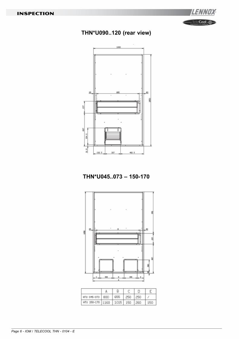
It is recommended to first prepare holes in the wall for theair intake and outlet flanges.The dimensions of the air outlet/intake flanges are shownbelow:
THN*D045...170 (rear view)
INSPECTION
INSPECTION
INSPECTION ON RECEIPT
On receiving the unit, check that it is perfectly intact: the unit leftthe factory in perfect conditions; immediately report any signs ofdamage to the carrier and note them on the Delivery Slip beforesigning it.HiRef S.p.A. or its Agent must be promptly notified of the entityof the damage. The Customer must submit a written reportdescribing every significant sign of damage.
Page 6 - IOM / TELECOOL THN - 0104 - E
THN*U045..073 – 150-170
INSPECTION
THN*U090..120 (rear view)

IOM / TELECOOL THN - 0104 - E Page 7
INSTALLATION
The THN package air-conditioning unit is suitable for allenvironments except aggressive ones. Do not place anyobstacles near the units and make sure that the air flow is notimpeded by obstacles and/or situations causing back suction.
The following steps should be carried out to ensure properinstallation:
- Apply a vibration-damping rubber lining between theunit and wall
- Position the unit on the wall, fitting the air outlet andintake flanges correctly into place
- carefully seal the entire perimeter of the unit on theinterior wall of the shelter and the air intake and outletflanges on the inside.
INSTALLATION
- In order to obtain stable indoor conditions, makesure that the shelter interior is insulated from theoutside; any openings should be sealed closed.
The recommended sizes for the power cables andemergency line are shown in the table below:
Unit model
THN045THN056THN073
THN090THN105
THN120THN150THN170
Mains power supply
230V/1Ph/50Hz
400V/3Ph+N/50Hz
Cable type
2 x 6mm2 + T 6mm2
4 x 6 mm2 +T x 6 mm2
UPS emergency line
48 Vdc/230Vac
48 Vdc/230Vac
Cable Type
2 x 2.5 mm2
2 x 4 mm2
Page 8 - IOM / TELECOOL THN - 0104 - E
INSTALLATION
Evacuation and charging operations for THN-type units
This type of work must be carried out by qualified personnel only trained to do their job inaccordance with current laws and regulations
1. Introduction
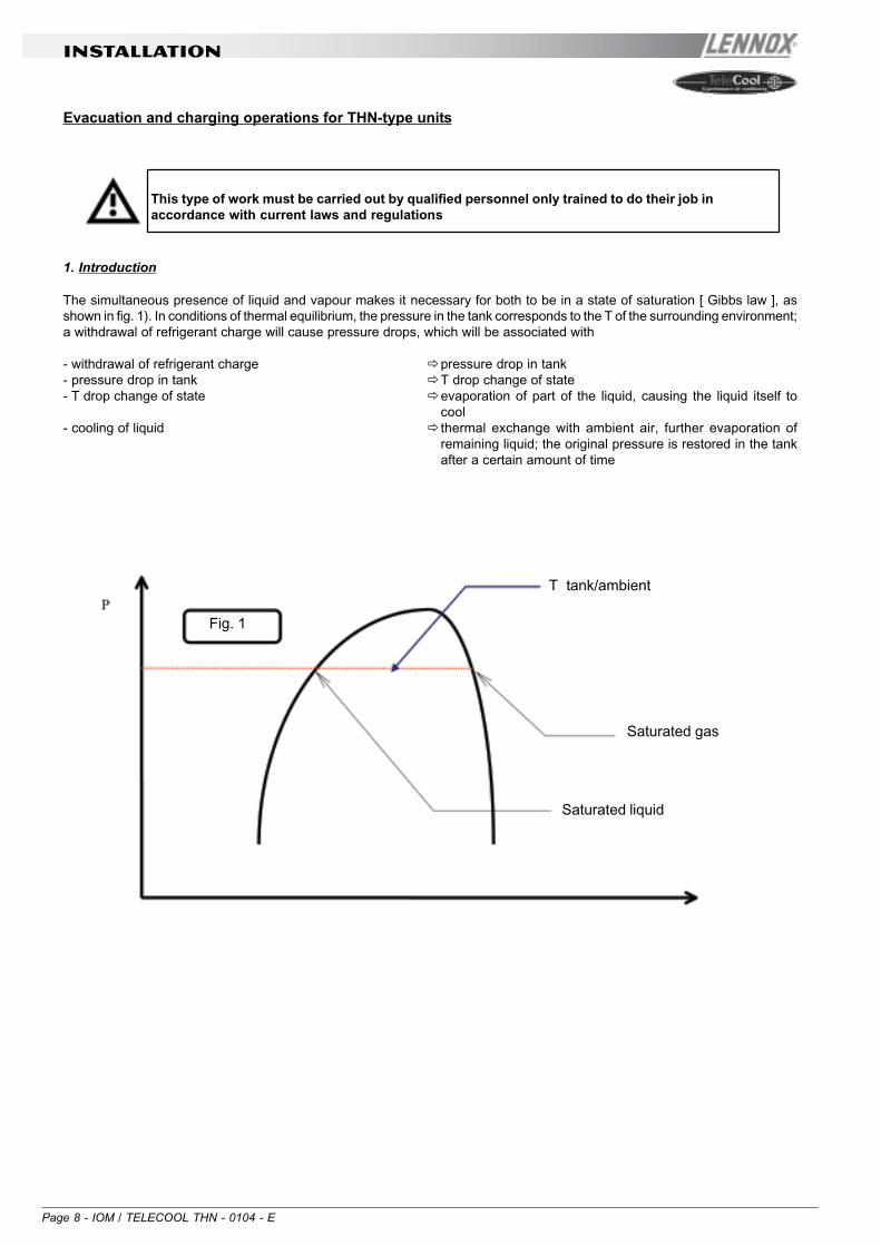
The simultaneous presence of liquid and vapour makes it necessary for both to be in a state of saturation [ Gibbs law ], asshown in fig. 1). In conditions of thermal equilibrium, the pressure in the tank corresponds to the T of the surrounding environment;a withdrawal of refrigerant charge will cause pressure drops, which will be associated with
- withdrawal of refrigerant charge pressure drop in tank- pressure drop in tank T drop change of state- T drop change of state evaporation of part of the liquid, causing the liquid itself to
cool- cooling of liquid thermal exchange with ambient air, further evaporation of
remaining liquid; the original pressure is restored in the tankafter a certain amount of time
Fig. 1
T tank/ambient
Saturated gas
Saturated liquid
IOM / TELECOOL THN - 0104 - E Page 9
INSTALLATION
2. Vacuum and charging machine
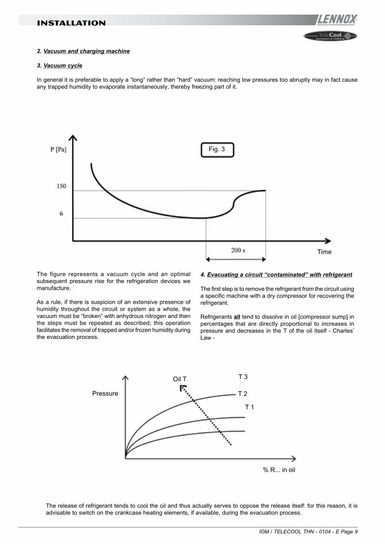
3. Vacuum cycle
In general it is preferable to apply a “long” rather than “hard” vacuum: reaching low pressures too abruptly may in fact causeany trapped humidity to evaporate instantaneously, thereby freezing part of it.
Fig. 3
Time
The figure represents a vacuum cycle and an optimalsubsequent pressure rise for the refrigeration devices wemanufacture.
As a rule, if there is suspicion of an extensive presence ofhumidity throughout the circuit or system as a whole, thevacuum must be “broken” with anhydrous nitrogen and thenthe steps must be repeated as described; this operationfacilitates the removal of trapped and/or frozen humidity duringthe evacuation process.
4. Evacuating a circuit “contaminated” with refrigerant
The first step is to remove the refrigerant from the circuit usinga specific machine with a dry compressor for recovering therefrigerant.
Refrigerants all tend to dissolve in oil [compressor sump] inpercentages that are directly proportional to increases inpressure and decreases in the T of the oil itself - Charles’Law -
Pressure
Oil T T 3
T 2
T 1
% R... in oil
The release of refrigerant tends to cool the oil and thus actually serves to oppose the release itself: for this reason, it isadvisable to switch on the crankcase heating elements, if available, during the evacuation process.

Page 10 - IOM / TELECOOL THN - 0104 - E
INSTALLATION
If a high % of refrigerant gets into contact with the Pirani gauge(vacuum sensor), it may “drug” the sensitive element of the latter,rendering it inefficient for a certain period of time. For this reason,if no machine for recovering refrigerant is available, it isnonetheless advisable to switch on the crankcase heatingelements and avoid applying a vacuum until the circuit has beenadequately purged of refrigerant: the refrigerant may in factsolubilize in the oil of the vacuum pump, undermining itsperformance for a long time (hours).
5. Charging positions [single point]
The best position for charging the air conditioners is the sectionbetween the thermostatic valve and the evaporator; care shouldbe taken to avoid fixing the thermostat bulb until the operationis complete: this is important to ensure that the valve orifice
remains open so as to allow the passage of refrigerant alsotoward the condenser/receiver.
Air-condensed water chillers should be charged withrefrigerant in the section between the condenser andthermostatic valve: this favours flow into the larger-sizedexchanger.
If possible, avoid the inflow of refrigerant into the compressoras this may cause excessive dilution of the lubricant; in anycase, first check the compatibility between the crankcasecapacity and the required charge volumes.
ELECTRICAL CONNECTIONS
GENERALITIES
Before carrying out any job onelectrical parts, make sure the powersupply is disconnected.
Check that the mains electricity supply is compatible with thespecifications (voltage, number of phases, frequency) shownon the unit rating plate.
The power connection for single-phase loads is to be made witha three-pole cable and “N” wire at the centre of the star [optional:power supply w/o neutral]
The size of the cable and lineprotections must conform to thespecifications provided in the wiringdiagram.
The supply voltage may not undergo fluctuations exceeding ±5%and the unbalance between phases must always be below 2%.
The above operating conditionsmust always be complied with:failure to ensure said conditionswill result in the immediateinvalidation of the warranty.
The electrical connections must be made in accordance withthe information shown in the wiring diagram provided withthe unit and with current and local regulations.
An earth connection is mandatory. The installer mustconnect the earthing wire using the earthing terminal situatedon the electric control board (yellow and green wire).
The power supply to the control circuit is taken from the powerline through an insulating transformer situated on the electriccontrol board.
The control circuit is protected by suitable fuses or automaticbreakers depending on the unit size.

IOM / TELECOOL THN - 0104 - E Page 11
STARTING UP
STARTING UP
PRELIMINARY CHECKS
- Check that the electrical connections have been madeproperly and that all the terminals are securely tightened.This check should also be included in a periodic six-monthinspection.
- Check that the voltage at the RST terminals is 400 V ±5% and make sure the yellow indicator light of the phasesequence relay is on. The phase sequence relay ispositioned on the electric control board; if the sequenceis not duly observed, it will not enable the machine to start.
- Make sure there are no refrigerant leaks that may havebeen caused by accidental impacts during transport and/or installation.
- Check the power supply to the crankcase heatingelements, where present.
The heating elements must be turnedon at least 12 hours before the unit isstarted. They are automaticallyactivated when the main switch is puton. Their function is to raise the T ofthe oil in the sump and limit thequantity of refrigerant dissolved in it.
To verify whether the heating elements are working properly,check the lower part of the compressors: it should be warm orin any case at a temperature 10 - 15 °C higher than the ambienttemperature.
The diagram above illustrates a specific property of gases[Charles’ Law], which are more soluble in liquids as thepressure increases but less soluble as the temperatureincreases: if the oil in the sump is held at a constant pressure,
an increase in temperature will significantly reduce the amountof refrigerant dissolved in it, thus ensuring that the desiredlubricating function is maintained.
Pressure
Oil T
% R407C in oil

Page 12 - IOM / TELECOOL THN - 0104 - E
STARTING UP
STARTING UP FOR THE FIRST TIME
Installation:
• Attention: the unit is filled with HFC R407C refrigerant.This refrigerant belongs to group I ( no toxic - nodangerous) according to EN Norm 378 and accordingthe specification contained into CEE law n° 2037/00.
• Install the unit in the computer room. Make sure thatthe air inlet grilles have more than 0,3 m free spacearound. [ left - right side ]
• The condensate discharge lines can suitably pass in
pre-sheared holes on the unit basament.
Electrical connections:
• Open electrical panel.
• Disconnect the main switch.
• Inlet cables holes are positioned on the bottom side
of the unit
• Connect the power supply and the earth connection
to the main switch and to the main earth connection.
• 3 phase versions only. In case of wrong phasesequence, the compressor will start in the oppositedirection: scroll compressors have to turn in one onlydirection. The phase sequence relay is connected inseries with the air flow switch, so that if wrong R-S-Toccurs an “FL” alarm on mP will appear. In this casedisconnect the power supply, reverse two phasesbefore the main switch and restart. NB: the R-S-Tphase sequence device is positioned in the left partof the E-Panel: green light means power presenceand the yellow light means correct phase sequence;if the yellow light doesn’t shine, switch of the mainswitch and reverse two cables before the main switch.
• Close the panel.
• Press button “ON” on the microprocessor keyboard.
Start Up
• Make sure that the air flows normally and the flow
switch alarm is not present.
• Press the “ON” button on the mP keyboard:
o The indoor fan will start immediatelyo After 20 second and if no alarm are
present, the compressor will start up. NB:the compressor will start if the indoorconditions are according the set pointpresetted in the mP.
• Check the air Delta T: it has to be between 7 and
10 °C.
• Check for refrigerant leakage.
Operation
• Use the microprocessor and the unit manuals

IOM / TELECOOL THN - 0104 - E Page 13
STARTING UP
STARTING OPERATION
Before starting the unit, turn the main switch on, select theoperating mode desired from the control panel and press the“ON” button on the control panel.
If the unit fails to start up, check if the servicethermostat has been set according to the nominalvalues provided
You should not disconnect the unit fromthe power supply during periods when itis inoperative but only when it is to betaken out of service for a prolongedperiod (e.g. at the end of the season). Toturn off the unit temporarily follow thedirections provided in the section 4.5.
CHECKS DURING OPERATION
- Check the phase sequence relay on the control board toverify whether the phases occur in the correct sequence:if they do not, disconnect the unit from power supply andinvert two phases of the incoming three-pole cable. Neverattempt to modify internal electrical connections: anyundue modifications will immediately invalidate thewarranty.
- Check that the temperature of the water entering theevaporator is close to the value set on the servicethermostat.

Page 14 - IOM / TELECOOL THN - 0104 - E
STARTING UP
CHECKING THE REFRIGERANT LEVEL
- After a few hours of operation, check whether the liquid levelindicator has a green ring: a yellow colour indicates thepresence of humidity in the circuit. In such a case the circuitmust be dehumidified by qualified personnel.
- Large quantities of bubbles should not appear through theliquid level indicator. A constant passage of numerousbubbles may indicate that the refrigerant level is low andneeds to be topped up. The presence of a few bubbles ishowever allowed, especially in the case of high-glide ternarymixtures such as HFC R407C
- Also check that the end-of-evaporation temperature shownon the pressure gauge (refer to the pressure gauge scalefor the refrigerant R407C, marked with the initials D.P. - DewPoint) is about 4 °C lower than the temperature of the waterleaving the evaporator.
- Make sure the overheating of the cooling fluid is limited tobetween 5 and 8 °C: to this end:
1) read the temperature indicated by a contact thermometerplaced on the compressor intake pipe;
2) read the temperature indicated on the scale of a pressuregauge likewise connected to the intake side; refer to thepressure gauge scale for the refrigerant R407C, markedwith the initials D.P. (Dew Point).The degree of overheating is given by the differencebetween the temperatures thus determined.
- Make sure that the Sub-cooling of the cooling fluid islimited to between 3 and 5°C: to this end:
1) read the temperature indicated by a contactthermometer placed on the compressor intake pipe;
2) read the temperature indicated on the scale of apressure gauge connected to the liquid inlet at thecondenser outlet; refer to the pressure gauge scalefor the refrigerant R407C, marked with the initials B.P.(Bubble Point).The degree of Sub-cooling is given by the differencebetween the temperatures thus determined.
Warning: all THN units are chargedwith R407C. Any top-ups must bemade using the same type ofrefrigerant. This operation is to beconsidered extraordinarymaintenance work and must beperformed by qualified personnel only.
Warning: the refrigerant R407Crequires “POE” polyolester oil of thetype and viscosity indicated on thecompressor rating plate.For no reason should oil of a differenttype be introduced into the oil circuit.
Real Pcompressoroutlet
Average T(T1+T2)/2
T1 (start of condensation)DEW POINT
T2 (end of condensation)BUBBLE POINT
Heat content h
- The difference between the Dew Point and Bubble Point is known as “GLIDE” and this is a characteristic property ofrefrigerant mixtures. If pure fluids are used, the phase change occurs at a constant T and thus the glide is equal to zero.

IOM / TELECOOL THN - 0104 - E Page 15
SETTING OPERATING PARAMETERS
SETTING OPERATING PARAMETERS
GENERALITIES
All the control devices are set and tested in the factorybefore the unit is dispatched. However, after the unithas been in service for a reasonable period of time youcan perform a check on the operating and safetydevices. The settings are shown in Tables II and III.
All servicing of the equipment is to be consideredextraordinary maintenance and may be carried out BYQUALIFIED TECHNICIANS ONLY: incorrect settingsmay cause serious damage to the unit and injuries topersons.
The operating parameters and control system settingsconfigurable by means of the microprocessor control arepassword protected if they have a potential impact onthe integrity of the unit.
TABLE II - SETTING OF CONTROL DEVICES
CONTROL DEVICE
Differential air pressure switch (outlet air flow)
Differential air pressure switch (dirty filter)
Pa
Pa
SET POINT
50
50
DIFFERENTIAL
30
20
CONTROL DEVICE
Maximum pressure switch
Minimum pressure switch
Modulating condensation control device
Time lapse between two compressor starts
Bars-r
Bars-r
Bars-r
s
ACTIVATION
28.0
2
14
480
DIFFERENTIAL
4
1.5
7
-
RESETTING
ManualAutomatic
-

Page 16 - IOM / TELECOOL THN - 0104 - E
SETTING OPERATING PARAMETERS
MAXIMUM PRESSURE SWITCH
The high pressure switch stops the compressor when the outletpressure exceeds the set value.
Warning: do not attempt to changethe setting of the maximum pressureswitch: Should the latter fail to tripin the event of a pressure increase,the pressure relief valve will open.
The high pressure switch must be manually reset; this is possibleonly when the pressure falls below the set differential (see TableIII).
MINIMUM PRESSURE SWITCH
The low pressure switch stops the compressor when theinlet pressure falls below the set value for more than 120seconds.
The switch is automatically reset when the pressure risesabove the set differential (see Table III);

IOM / TELECOOL THN - 0104 - E Page 17
ROUTINE MAINTENANCE AND CHECKS
ROUTINE MAINTENANCE AND CHECKS
The only operations to be performed by the user are to switchthe unit on and off.All other operations are to be considered maintenance workand must thus be carried out by qualified personnel trainedto do their job in accordance with current laws and regulations.
WARNINGS
All the operations described in thischapter MUST ALWAYS BEPERFORMED BY QUALIFIEDPERSONNEL ONLY.
Before carrying out any work on theunit or accessing internal parts, makesure you have disconnected it from themains electricity supply.
The upper part and the outlet pipe ofthe compressor reach hightemperatures. Be especially carefulwhen working in the surrounding areawith the panels off.
Be especially careful when working inproximity to finned coils since the 0.11mm-thick aluminium fins can causesuperficial injuries due to cuts.
After completing maintenance jobs,always replace the panels enclosingthe units and secure them with thefastening screws provided.

Page 18 - IOM / TELECOOL THN - 0104 - E
ROUTINE MAINTENANCE AND CHECKS
GENERALITIES
To guarantee a constantly satisfactory performance over time, it is advisable to carry out routine maintenance andchecks as described below. The indications below are related to standard tear and wear.
Operation
• Check the efficiency of all the control and safety devices• Check the terminals on the electric control board and compressor terminal boards to
ensure that they are securely tightened. The movable and fixed contacts of the circuitbreakers must be periodically cleaned and replaced whenever they show signs ofdeterioration
• Check the refrigerant level by means of the liquid level indicator• Check the efficiency of the differential air pressure switch and dirty filter differential pressure
switch• Check the condition of the air filter and replace it if necessary• Check the humidity indicator (green=dry, yellow=humid) on the liquid level indicator; if the
indicator is not green as shown on the indicator sticker, replace the filter
Frequency
Once a yearOnce a year
Every 6 mos.Every 6 mos.
Every 6 mos.Every 6 mos.
INSPECTING THE AIR FILTER
– Remove the panel above the condenser fan to access the damper and air filter compartment.– Pull out the air filter.– Check the condition of the filter and replace it if necessary

IOM / TELECOOL THN - 0104 - E Page 19
ROUTINE MAINTENANCE AND CHECKS
INSPECTING THE DAMPER SERVOMOTOR
– Remove the panel above the condenser fan– Remove the damper fastening screws (see fig. below)
– Pull out the entire damper section to access the servomotor

Page 20 - IOM / TELECOOL THN - 0104 - E
ROUTINE MAINTENANCE AND CHECKS
REPAIRING THE COOLING CIRCUIT
Warning: while performing repairs on thecooling circuit or maintenance work onthe compressors, make sure the circuitis left open for as little time as possible.Even if briefly exposed to air, ester oilstend to absorb large amounts ofhumidity, which results in the formationof weak acids.
If the cooling circuit has undergone any repairs, the followingoperations must be carried out:
- tightness test;- evacuation and drying of the cooling circuit;- charging with refrigerant.
If the system has to be drained, alwaysrecover the refrigerant present in thecircuit using suitable equipment; therefrigerant should be handledexclusively in the liquid phase.

IOM / TELECOOL THN - 0104 - E Page 21
ROUTINE MAINTENANCE AND CHECKS
TIGHTNESS TEST
Fill the circuit with anhydrous nitrogen supplied from a tankwith a pressure-reducing valve until the pressure rises to 22bars.
During the pressurisation phase, do notexceed a pressure of 22 bars on thecompressor low pressure side.
The presence of any leaks must be determined using specialleak detectors. Should any leaks be detected during the test,empty out the circuit before repairing the leaks with suitablealloys.
Do not use oxygen in the place ofnitrogen as a test agent, since thiswould cause a risk of explosion.
HARD VACUUM AND DRYING OF COOLING CIR-CUIT
To achieve a hard vacuum in the cooling circuit it is necessaryto use a pump capable of generating a high degree of vacuum,i.e. 150 Pa of absolute pressure with a capacity ofapproximately 10 m3/h. If such a pump is available, oneevacuation will normally suffice to achieve an absolute pressureof 150 Pa.
If there is no such vacuum pump available, or whenever thecircuit has remained open for long periods of time, you arestrongly recommended to adopt the triple evacuation method.This method is also recommended when there is a presenceof humidity within the circuit.
The vacuum pump should be connected to the inlets.
The procedure to be carried out is as follows:
- Evacuate the circuit until you reach an absolute pressure ofat least 350 Pa: at this point inject nitrogen into the circuituntil you reach a relative pressure of about 1 bar.
- Repeat the step described above.
- Carry out the step described above for the third time, but inthis case attempting to reach the hardest vacuum possible.
Using this procedure you can easily remove up to 99% ofpollutants.

Page 22 - IOM / TELECOOL THN - 0104 - E
ROUTINE MAINTENANCE AND CHECKS
RECHARGING WITH REFRIGERANT R407C
- Connect the tank of refrigerant gas to the male 1/4 SAE inletsituated on the liquid line after discharging a little gas toeliminate air in the connection pipe.
- Fill with refrigerant in liquid form until you reach 75% ofthe total charge.
- Then connect to the inlet on the pipe between the thermostaticvalve and evaporator and complete the charging processwith the refrigerant in liquid form until no more bubbles canbe seen on the liquid level indicator and the operatingparameters specified in section 4.4 have been reached.
Since R407C is a ternary mixture,charging must take place exclusivelywith liquid refrigerant to ensure thecorrect percentages of the threeconstituents.Introduce refrigerant through the inletin the liquid line.
A unit that was originally charged withR407C in the factory must not becharged with R22 or other refrigerantswithout the written authorisation ofHiRef S.p.A.
ENVIRONMENTAL PROTECTION
The law implementing the regulations [reg. EEC 2037/00] whichgovern the use of ozone-depleting substances and greenhousegases bans the dispersal of refrigerant gases in theenvironment and requires whoever is in their possession torecover them and, at the end of their useful life, either to returnthem to the dealer or take them to a suitable waste disposalfacility.
The refrigerant HFC R407C is not harmful to the ozone layerbut is included among the substances responsible for thegreenhouse effect and thus falls within the scope of theaforesaid regulations.
Therefore, special care should be takenwhen carrying out maintenance work tominimise refrigerant leaks.

IOM / TELECOOL THN - 0104 - E Page 23
TROUBLESHOOTING
TROUBLESHOOTING
On the next pages you will find a list of the most commoncauses that may cause the package unit to fail or malfunction.These causes are broken down according to easily identifiablesymptoms.
You should be extremely careful whenattempting to implement any of the possibleremedies suggested: overconfidence canresult in injuries, even serious ones, to inexpertindividuals. Therefore, once the cause hasbeen identified, you are advised to contact themanufacturer or a qualified technician for help.
FAULT
The unit does not start
The compressor is noisy
Presence of abnormally highpressure
Possible causes
No power supply
The electronic card is cut off from thepower supplyAlarms have been triggered
The phase sequence is wrong
The compressor is rotating in the wrongdirection
Insufficient flow of air to the condenser
Presence of air in the refrigerant circuit,as revealed by the presence of bubblesin the flow indicator also withundercooling values exceeding 5 °C
Corrective actions
Check that power is being supplied bothto the primary and auxiliary circuits.
Check the fuses
Check whether any alarms are signalledon the microprocessor control panel,eliminate the causes and restart the unit.Invert two phases in the primary powerline after disconnecting them upstreamfrom the unit
Check the phase sequence relay. Invertthe phases on the terminal board afterdisconnecting the unit and contact themanufacturer.
Check for the presence of obstructionsin the condenser section ventilationcircuitCheck whether the condenser coilsurface is obstructedCheck the condensation control device[optional]
Drain and pressurise the circuit andcheck for leaks. Evacuate slowly [formore than 3 hours] until reaching apressure of 0.1 Pa and then recharge inthe liquid phase

Page 24 - IOM / TELECOOL THN - 0104 - E
TROUBLESHOOTING
FAULT
Presence of abnormally highpressure
Low condensation pressure
Low evaporation pressure
The compressor does not start
Possible causes
Unit overcharged, as revealed by anSub-cooling of more than 8 °C
Thermostatic valve and/or filterobstructed. These symptoms may alsooccur in the presence of an abnormallylow pressure
Transducer fault
Malfunctioning of thermostatic valve
Filter dryer clogged
Low condensation T
Low level of refrigerant
The internal thermal protection devicehas tripped
The circuit breakers or line fuses havebeen tripped by a short circuit
One of the high or low pressure switcheshas tripped
The phases have been inverted in thedistribution compartment
Corrective actions
Drain the circuit
Check the temperatures upstream anddownstream from the valve and filter andreplace them if necessary.
Check the efficiency of the condensationcontrol device [optional]
Warming the bulb with your hand, checkwhether the valve opens and adjust it ifnecessary. If it does not respond,replace it.
Pressure drops upstream anddownstream from the filter should notexceed 2°C. If they do, replace the filter.
Check the efficiency of the condensationcontrol device [where present]
Check the refrigerant level by measuringthe degree of Sub-cooling; if it is below2°C replenish the charge
In the case of compressors equippedwith a protection module, check thethermal contact. Identify the causes afterrestarting.
Pinpoint the cause by measuring theresistance of the individual windings andthe insulation from the casing beforerestoring power.
Check on the microprocessor, eliminatethe causes.
Check the phase sequence relay.

IOM / TELECOOL THN - 0104 - E Page 25
Technical data
TECHNICAL DATA
Model
Refrigerant
Cooling Capacity@27°/40%-35°
Standard Power Supply
Power Supply (Option 2)
Power Supply (Option 3)
Power Supply (Option 4)
Power Supply (Option 5)
Total Absorbed Power
Total Absorbed Current
FLA
LRA
Indoor Fan(s) absorbedPower in 230/1/50 execution
Indoor Fan(s) absorbedPower in 48 V DC execution(optional)
Indoor Air Flow
Indoor Air Flow during FreeCooling Operations @ 40 Pa
Full Free CoolingTemperature
Filtration
Sound Power Level
Outdoor Noise Level:SPL @ 2m FF
Type of compressor
Number ofrefrigerating circuits
Number of compressors
Oil charge per compressor
Indoor Coil Front Surface
Outdoor Coil Front Surface
Condenser Air Flow
Number of condenser’s fan
Overall dimensions: height H
Overall dimensions: lenght L
Overall dimensions: depth D
Weight
[Ashrae]
[W]
[V-n-f]
[V-n-f]
[V-n-f]
[V-n-f]
[V-n-f]
[W]
[A]
[A]
[A]
[W]
[W]
[m3/h]
[m3/h]
[°C]
[-]
[dB-A]
[dB-A]
[-]
[-]
[-]
[dm3]
[m2]
[m2]
[m3/h]
[-]
[mm]
[mm]
[mm]
kg
THN 045
R407C
4500
230/1/50
-
230/1/50+230/1/50
230/1/50+48 VDC
-
1810
8.3
15.1
30
108
100
1450
1320
17,8
EU3
69
58
Rotary
1
1
0.44
0.30
0.33
2250
1
800
1850
550
120
THN 056
R407C
5600
230/1/50
400/3/50
400/3/50+230/1/50
230/1/50+48 VDC
400/3/50+48 VDC
2330
14.3
16
47
108
100
1450
1320
15,5
EU3
69
58
Scroll
1
1
1
0.30
0.33
2250
1
800
1850
550
128
THN 073
R407C
7100
230/1/50
400/3/50
400/3/50+230/1/50
230/1/50+48 VDC
400/3/50+48 VDC
2990
13.6
19.6
61
310
260
2100
1980
17.0
EU3
69
58
Scroll
1
1
1
0.30
0.33
2250
1
800
1850
550
135
THN 090
R407C
8970
400/3/50
230/1/50
400/3/50+230/1/50
400/3/50+48 VDC
230/1/50+48 VDC
3950
11.8
17.5
40
470
350
3020
2850
18.2
EU3
72
61
Scroll
1
1
1.1
0.38
0.45
3750
1 (THN)2 (THN*D)
1010
1850
550
195
THN 105
R407C
10850
400/3/50
230/1/50
400/3/50+230/1/50
400/3/50+48 VDC
230/1/50+48 VDC
4400
12.5
17.5
46
470
350
3020
2810
16.3
EU3
72
61
Scroll
1
1
1.1
0.38
0.45
3750
1 (THN)2 (THN*D)
1010
1850
550
200
THN 120
R407C
11850
400/3/50
230/1/50
400/3/50+230/1/50
400/3/50+48 VDC
230/1/50+48 VDC
5000
13.6
19.5
50
470
350
3020
2810
15.4
EU3
72
61
Scroll
1
1
1.1
0.38
0.45
3750
1 (THN)2 (THN*D)
1010
1850
550
210
THN 150
R407C
14980
400/3/50
-
400/3/50+230/1/50
400/3/50+48 VDC
-
6040
17.8
21.7
65
520
450
3800
3550
15.3
EU3
72
61
Scroll
1
1
1.36
0.42
0.52
4700
2
1160
1850
550
245
THN 170
R407C
17200
400/3/50
-
400/3/50+230/1/50
400/3/50+48 VDC
-
7030
18.6
25.7
74
520
450
3800
3550
13.6
EU3
72
61
Scroll
1
1
1.65
0.42
0.52
4700
2
1160
1850
550
250

www.lennoxeurope.com
www.lennoxbelgium.com
www.lennoxczech.com
www.lennoxfrance.com
www.lennoxdeutschland.com
www.lennoxnederland.com
www.lennoxpolska.com
www.lennoxportugal.com
www.lennoxrussia.com
www.lennoxdistribution.com
www.lennoxspain.com
www.lennoxukraine.com
www.lennoxuk.com
www.lennoxdistribution.com
TELECOOL THN-IOM-0104-E
BELGIUM, LUXEMBOURG
CZECH REPUBLIC
FRANCE
GERMANY
NETHERLANDS
POLAND
PORTUGAL
RUSSIA
SLOVAKIA
SPAIN
UKRAINE
UNITED KINGDOM AND IRELAND
OTHER COUNTRIES
Due to Lennox’s ongoing commitment to quality,
the Specifications, Ratings and Dimensions are
subject to change without notice and without
incurring liability.
Improper installation, adjustment, alteration,
service or maintenance can cause property
damage or personal injury.
Installation and service must be performed by a
qualified installer and servicing agency.