Embed Size (px)
Citation preview
lennoxemeia.com
AIRCOOLAIRCOMPACTAIR
CIC - CIH
Installation, operatingand maintenance
Indoor unit
MIL121E-1401 / 06-2013Translation of original manual

• 1 •
3
4
1 -1.1 5
1.2 5
1.3 7
1.4 12
2 - 2.1 14
2.2 14
2.3 15
2.4 15
2.5 15
2.6 16
2.7 17
3 -3.1 22
4 -4.1 23
4.2 23
AIRCOOLAIR/COMPACTAIR - CIC/CIH - MIL121E-1401 / 06-2013
WARNING: Read this manual before carrying out installation, repair or maintenance work.
All the technical and technological information contained in this manual, including any drawings and technical descriptions provided by us, remain the property of Lennox and must not be utilised (except in the operation of this product), reproduced, issued to or made available to third parties without the prior written agreement of Lennox.
INSTALLATIONOPERATIONMAINTENANCE MANUAL
Ref : MIL121E-1401 / 06-2013
TABLE OF CONTENTS
AIRCOOLAIR/COMPACTAIRINDOOR UNITS
POINTS TO BEAR IN MINDManufacturer’s recommended inspections
DATA PAGE FOR COMMISSIONING OF THE UNIT
GENERAL CHARACTERISTICSPhysical data
Electrical data
Fan performance
Unit dimensions
INSTALLATIONInstallation guidelinesOptional task prior to unit installation : regulating airfl ow in the fansService space
Drainage
Refrigerant connections
Electrical connections
Installation of options
COMMISSIONING AND OPERATIONPreliminary checks
MAINTENANCEPreventive maintenance
Fault diagnosis
• 2 • AIRCOOLAIR/COMPACTAIR - CIC/CIH - MIL121E-1401 / 06-2013
• 3 •AIRCOOLAIR/COMPACTAIR - CIC/CIH - MIL121E-1401 / 06-2013
POINTS TO BEAR IN MIND
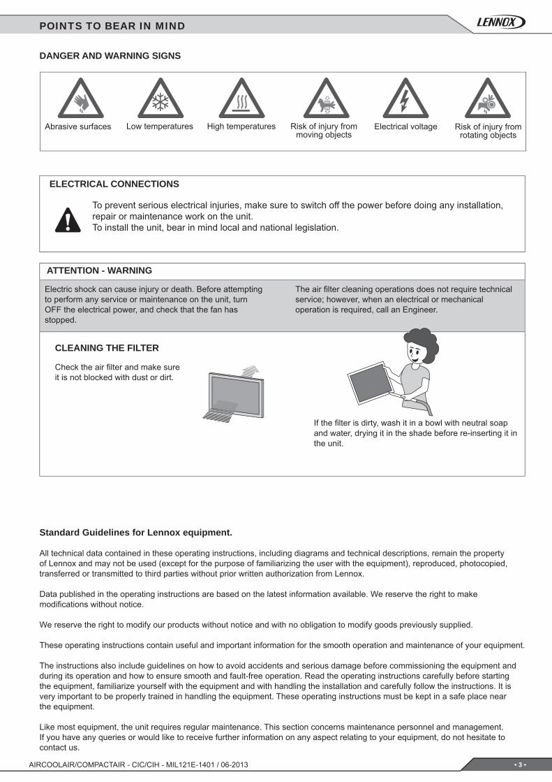
DANGER AND WARNING SIGNS
Abrasive surfaces Low temperatures High temperatures Risk of injury from moving objects
Electrical voltage Risk of injury from rotating objects
ELECTRICAL CONNECTIONS
To prevent serious electrical injuries, make sure to switch off the power before doing any installation, repair or maintenance work on the unit.To install the unit, bear in mind local and national legislation.
ATTENTION - WARNING
Electric shock can cause injury or death. Before attempting to perform any service or maintenance on the unit, turn OFF the electrical power, and check that the fan has stopped.
The air fi lter cleaning operations does not require technical service; however, when an electrical or mechanical operation is required, call an Engineer.
CLEANING THE FILTER
Check the air fi lter and make sure it is not blocked with dust or dirt.
If the fi lter is dirty, wash it in a bowl with neutral soap and water, drying it in the shade before re-inserting it in the unit.
Standard Guidelines for Lennox equipment.
All technical data contained in these operating instructions, including diagrams and technical descriptions, remain the property of Lennox and may not be used (except for the purpose of familiarizing the user with the equipment), reproduced, photocopied, transferred or transmitted to third parties without prior written authorization from Lennox.
Data published in the operating instructions are based on the latest information available. We reserve the right to make modifi cations without notice.
We reserve the right to modify our products without notice and with no obligation to modify goods previously supplied.
These operating instructions contain useful and important information for the smooth operation and maintenance of your equipment.
The instructions also include guidelines on how to avoid accidents and serious damage before commissioning the equipment and during its operation and how to ensure smooth and fault-free operation. Read the operating instructions carefully before starting the equipment, familiarize yourself with the equipment and with handling the installation and carefully follow the instructions. It is very important to be properly trained in handling the equipment. These operating instructions must be kept in a safe place near the equipment.
Like most equipment, the unit requires regular maintenance. This section concerns maintenance personnel and management.If you have any queries or would like to receive further information on any aspect relating to your equipment, do not hesitate to contact us.
• 4 • AIRCOOLAIR/COMPACTAIR - CIC/CIH - MIL121E-1401 / 06-2013
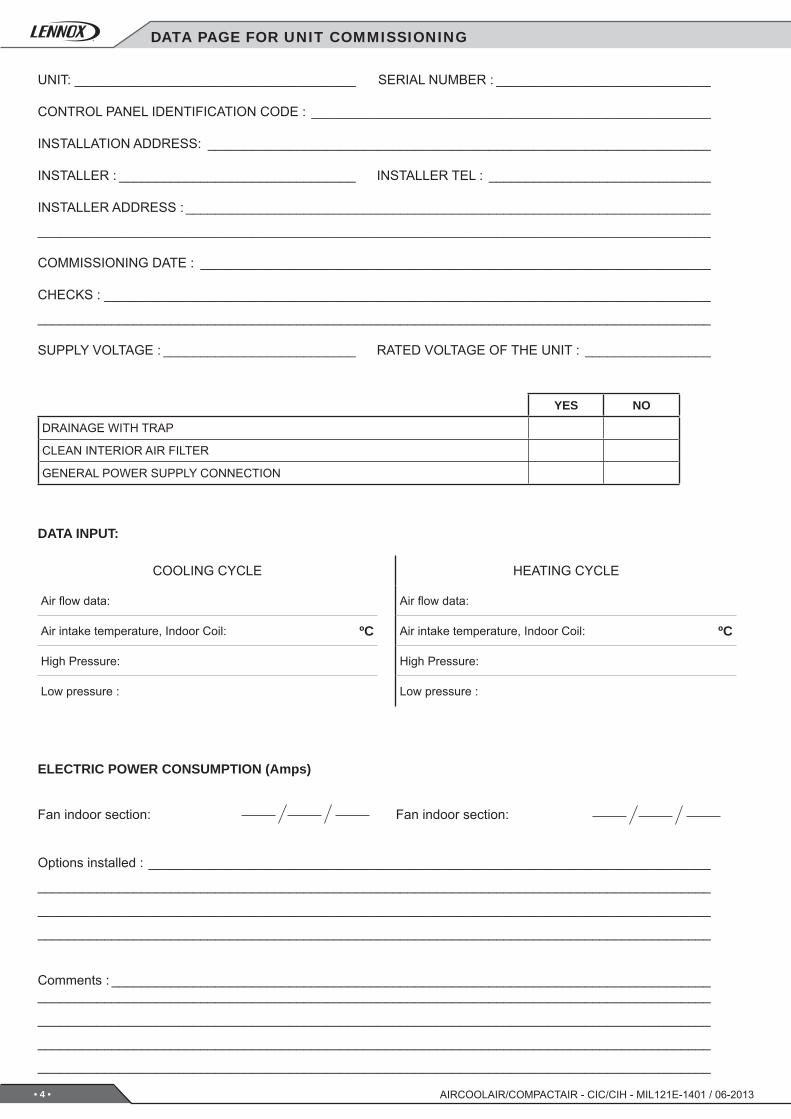
DATA PAGE FOR UNIT COMMISSIONING
COOLING CYCLE
Air fl ow data:
Air intake temperature, Indoor Coil: ºC
High Pressure:
Low pressure :
HEATING CYCLE
Air fl ow data:
Air intake temperature, Indoor Coil: ºC
High Pressure:
Low pressure :
YES NO
DRAINAGE WITH TRAP
CLEAN INTERIOR AIR FILTER
GENERAL POWER SUPPLY CONNECTION
DATA INPUT:
ELECTRIC POWER CONSUMPTION (Amps)
Fan indoor section: Fan indoor section:
UNIT: ______________________________________ SERIAL NUMBER : _____________________________
CONTROL PANEL IDENTIFICATION CODE : ______________________________________________________
INSTALLATION ADDRESS: ____________________________________________________________________
INSTALLER : ________________________________ INSTALLER TEL : ______________________________
INSTALLER ADDRESS : _______________________________________________________________________
___________________________________________________________________________________________
COMMISSIONING DATE : _____________________________________________________________________
CHECKS : __________________________________________________________________________________
___________________________________________________________________________________________
SUPPLY VOLTAGE : __________________________ RATED VOLTAGE OF THE UNIT : _________________
Options installed : ____________________________________________________________________________
___________________________________________________________________________________________
___________________________________________________________________________________________
___________________________________________________________________________________________
Comments : ____________________________________________________________________________________________________________________________________________________________________________
___________________________________________________________________________________________
___________________________________________________________________________________________
___________________________________________________________________________________________
• 5 •
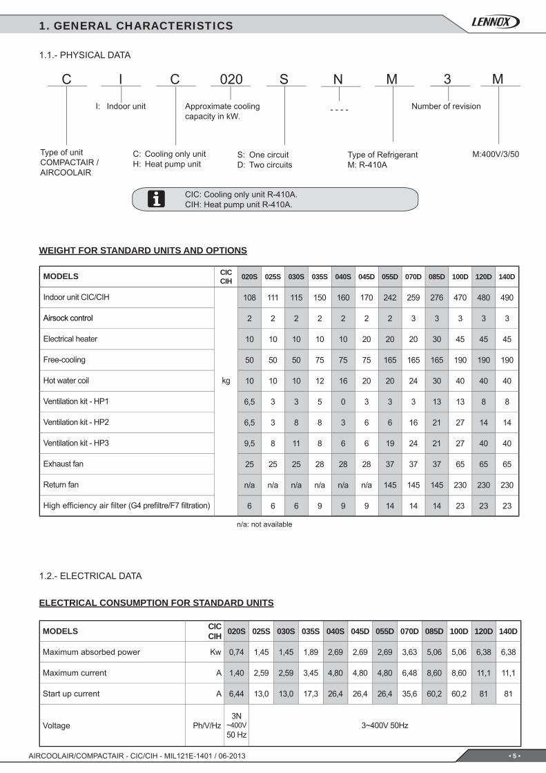
C I C 020 S N M 3 M
CICCIH 020S 025S 030S 035S 040S 045D 055D 070D 085D 100D 120D 140D
108 111 115 150 160 170 242 259 276 470 480 490
2 2 2 2 2 2 2 3 3 3 3 3
10 10 10 10 10 20 20 20 30 45 45 45
50 50 50 75 75 75 165 165 165 190 190 190
10 10 10 12 16 20 20 24 30 40 40 40
6,5 3 3 5 0 3 3 3 13 13 8 8
6,5 3 8 8 3 6 6 16 21 27 14 14
9,5 8 11 8 6 6 19 24 21 27 40 40
25 25 25 28 28 28 37 37 37 65 65 65
n/a n/a n/a n/a n/a n/a 145 145 145 230 230 230
6 6 6 9 9 9 14 14 14 23 23 23
CICCIH 020S 025S 030S 035S 040S 045D 055D 070D 085D 100D 120D 140D
0,74 1,45 1,45 1,89 2,69 2,69 2,69 3,63 5,06 5,06 6,38 6,38
1,40 2,59 2,59 3,45 4,80 4,80 4,80 6,48 8,60 8,60 11,1 11,1
6,44 13,0 13,0 17,3 26,4 26,4 26,4 35,6 60,2 60,2 81 81
3N~400V50 Hz
3~400V 50Hz
M:400V/3/50
- - - -
AIRCOOLAIR/COMPACTAIR - CIC/CIH - MIL121E-1401 / 06-2013
1. GENERAL CHARACTERISTICS
1.1.- PHYSICAL DATA
Type of unitCOMPACTAIR /AIRCOOLAIR
I: Indoor unit
Type of Refrigerant M: R-410A
Approximate cooling capacity in kW.
S: One circuitD: Two circuits
CIC: Cooling only unit R-410A.CIH: Heat pump unit R-410A.
1.2.- ELECTRICAL DATA
ELECTRICAL CONSUMPTION FOR STANDARD UNITS
WEIGHT FOR STANDARD UNITS AND OPTIONS
C: Cooling only unitH: Heat pump unit
Number of revision
MODELS
Indoor unit CIC/CIH
Airsock control
Electrical heater
Free-cooling
Hot water coil kg
Ventilation kit - HP1
Ventilation kit - HP2
Ventilation kit - HP3
Exhaust fan
Return fan
High effi ciency air fi lter (G4 prefi ltre/F7 fi ltration)
MODELS
Maximum absorbed power Kw
Maximum current A
Start up current A
Voltage Ph/V/Hz
n/a: not available
• 6 •
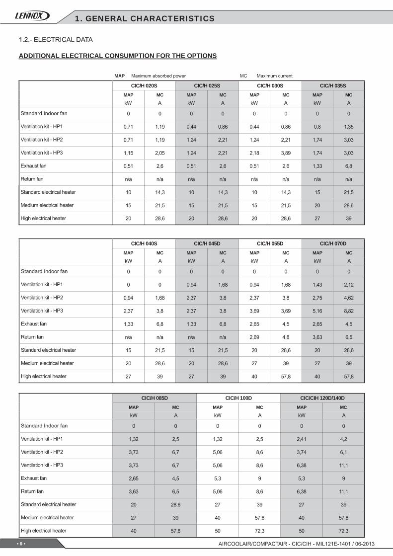
CIC/H 020S CIC/H 025S CIC/H 030S CIC/H 035SMAP MC MAP MC MAP MC MAP MC
0 0 0 0 0 0 0 0
0,71 1,19 0,44 0,86 0,44 0,86 0,8 1,35
0,71 1,19 1,24 2,21 1,24 2,21 1,74 3,03
1,15 2,05 1,24 2,21 2,18 3,89 1,74 3,03
0,51 2,6 0,51 2,6 0,51 2,6 1,33 6,8
n/a n/a n/a n/a n/a n/a n/a n/a
10 14,3 10 14,3 10 14,3 15 21,5
15 21,5 15 21,5 15 21,5 20 28,6
20 28,6 20 28,6 20 28,6 27 39
CIC/H 040S CIC/H 045D CIC/H 055D CIC/H 070DMAP MC MAP MC MAP MC MAP MC
0 0 0 0 0 0 0 0
0 0 0,94 1,68 0,94 1,68 1,43 2,12
0,94 1,68 2,37 3,8 2,37 3,8 2,75 4,62
2,37 3,8 2,37 3,8 3,69 3,69 5,16 8,82
1,33 6,8 1,33 6,8 2,65 4,5 2,65 4,5
n/a n/a n/a n/a 2,69 4,8 3,63 6,5
15 21,5 15 21,5 20 28,6 20 28,6
20 28,6 20 28,6 27 39 27 39
27 39 27 39 40 57,8 40 57,8
CIC/H 085D CIC/H 100D CIC/CIH 120D/140DMAP MC MAP MC MAP MC
0 0 0 0 0 0
1,32 2,5 1,32 2,5 2,41 4,2
3,73 6,7 5,06 8,6 3,74 6,1
3,73 6,7 5,06 8,6 6,38 11,1
2,65 4,5 5,3 9 5,3 9
3,63 6,5 5,06 8,6 6,38 11,1
20 28,6 27 39 27 39
27 39 40 57,8 40 57,8
40 57,8 50 72,3 50 72,3
AIRCOOLAIR/COMPACTAIR - CIC/CIH - MIL121E-1401 / 06-2013
1. GENERAL CHARACTERISTICS
1.2.- ELECTRICAL DATA
ADDITIONAL ELECTRICAL CONSUMPTION FOR THE OPTIONS
kW A kW A kW A kW A
Standard Indoor fan
Ventilation kit - HP1
Ventilation kit - HP2
Ventilation kit - HP3
Exhaust fan
Return fan
Standard electrical heater
Medium electrical heater
High electrical heater
kW A kW A kW A kW A
Standard Indoor fan
Ventilation kit - HP1
Ventilation kit - HP2
Ventilation kit - HP3
Exhaust fan
Return fan
Standard electrical heater
Medium electrical heater
High electrical heater
kW A kW A kW A
Standard Indoor fan
Ventilation kit - HP1
Ventilation kit - HP2
Ventilation kit - HP3
Exhaust fan
Return fan
Standard electrical heater
Medium electrical heater
High electrical heater
MAP Maximum absorbed power MC Maximum current
• 7 •
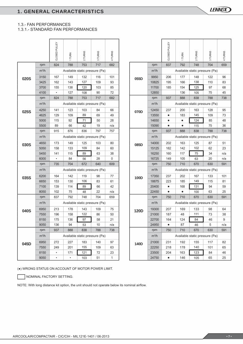
020S
824 788 753 717 682
3150 167 149 132 116 1013425 162 143 127 109 933700 155 138 120 103 854100 • 127 108 90 72
025S
824 788 753 717 682
4250 141 123 103 84 664625 129 109 89 69 495000 115 92 71 50 285500 89 66 42 19 n/a
030S
915 876 836 797 757
4650 173 149 125 103 805050 158 133 109 84 605450 141 115 89 63 386000 • 84 56 28 0
035S
735 704 672 640 609
6200 164 142 119 98 776650 153 130 106 83 617100 139 114 89 66 428050 102 75 48 22 n/a
040S
837 792 748 704 659
6950 213 178 143 109 757550 196 158 122 86 508150 175 136 97 58 219050 136 94 53 10 n/a
045D
937 888 838 788 738
6950 272 227 183 140 977550 249 201 155 109 638150 • 171 121 72 239050 • • 103 51 1
055D
837 792 748 704 659
9950 206 177 148 122 9610825 195 166 138 110 8311700 185 154 125 97 6812850 136 105 75 45
070D
937 888 838 788 738
12450 237 200 163 128 9513550 • 183 145 109 7314650 • • 124 85 4815090 • • 115 75 36
085D
937 888 838 788 738
14000 202 163 125 87 5115125 182 142 102 62 2316250 160 117 75 34 n/a16725 149 105 63 20 n/a
100D
750 710 670 630 591
17350 237 202 167 133 10118875 223 185 149 115 8120400 • 168 131 94 5922450 • • 100 63 25
120D
750 710 670 630 591
19300 207 169 133 98 6421000 187 48 111 73 3822700 164 124 84 46 924950 • 87 46 5 n/a
140D
750 710 670 630 591
21000 231 192 155 117 8222250 218 178 140 101 6523500 204 163 123 84 4624750 • 146 105 65 25
AIRCOOLAIR/COMPACTAIR - CIC/CIH - MIL121E-1401 / 06-2013
1.3.- FAN PERFORMANCES1.3.1.- STANDARD FAN PERFORMANCES
CLO
SED
PU
LLEY
1 TU
RN
2 TU
RN
S
3 TU
RN
S
4 TU
RN
S
rpm
m3/h Available static pressure (Pa)
rpm
m3/h Available static pressure (Pa)
rpm
m3/h Available static pressure (Pa)
rpm
m3/h Available static pressure (Pa)
rpm
m3/h Available static pressure (Pa)
rpm
m3/h Available static pressure (Pa)
CLO
SED
PU
LLEY
1 TU
RN
2 TU
RN
S
3 TU
RN
S
4 TU
RN
S
rpm
m3/h Available static pressure (Pa)
rpm
m3/h Available static pressure (Pa)
rpm
m3/h Available static pressure (Pa)
rpm
m3/h Available static pressure (Pa)
rpm
m3/h Available static pressure (Pa)
rpm
m3/h Available static pressure (Pa)
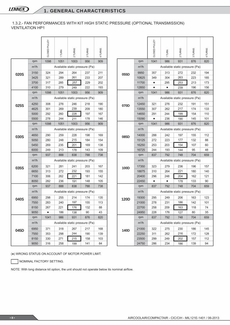
(●) WRONG STATUS ON ACCOUNT OF MOTOR POWER LIMIT.
NOTE: With long distance kit option, the unit should not operate below its nominal airfl ow.
NOMINAL FACTORY SETTING.
1. GENERAL CHARACTERISTICS
• 8 •
020S
1098 1051 1003 956 909
3150 324 294 264 237 2113425 321 289 261 233 2073700 317 285 257 229 2024100 310 279 249 222 193
025S
1098 1051 1003 956 909
4250 308 276 246 218 1904625 301 269 239 209 1805000 292 260 228 197 1675500 278 244 211 178 146
030S
1098 1051 1003 956 909
4650 290 259 228 198 1695050 280 248 215 184 1545450 269 235 201 169 1386000 249 213 178 143 109
035S
937 888 838 788 738
6200 321 281 241 203 1676650 313 272 232 193 1557100 306 262 221 181 1428050 282 236 191 148 105
040S
937 888 838 788 738
6950 298 255 214 174 1357550 283 240 197 155 1138150 267 221 176 132 889050 • 186 138 90 43
045D
1041 986 931 876 820
6950 371 318 267 217 1687550 353 298 244 190 1398150 330 271 215 158 1039050 316 258 199 141 84
055D
1041 986 931 876 820
9950 357 313 272 232 19410825 349 304 263 223 18511700 • 295 253 213 17312850 • • 239 196 156
070D
1041 986 931 876 820
12450 321 276 232 191 15113550 307 262 217 174 13314650 291 244 199 154 11015090 • 236 190 145 101
085D
1041 986 931 876 820
14000 288 242 197 155 11215125 272 223 177 132 8816250 253 203 154 107 6016725 244 193 144 95 48
100D
837 792 748 704 659
17350 323 279 236 196 15718875 310 264 221 180 14020400 296 248 204 162 12122450 • • 178 133 90
120D
837 792 748 704 659
19300 295 249 206 163 12321000 278 231 186 142 10122700 258 209 163 118 7424950 228 176 127 80 35
140D
837 792 748 704 659
21000 322 275 230 186 14522250 311 262 216 172 12823500 299 249 202 157 11224750 286 234 186 139 94
AIRCOOLAIR/COMPACTAIR - CIC/CIH - MIL121E-1401 / 06-2013
CLO
SED
PU
LLEY
1 TU
RN
2 TU
RN
S
3 TU
RN
S
4 TU
RN
S
rpm
m3/h Available static pressure (Pa)
rpm
m3/h Available static pressure (Pa)
rpm
m3/h Available static pressure (Pa)
rpm
m3/h Available static pressure (Pa)
rpm
m3/h Available static pressure (Pa)
rpm
m3/h Available static pressure (Pa)
CLO
SED
PU
LLEY
1 TU
RN
2 TU
RN
S
3 TU
RN
S
4 TU
RN
S
rpm
m3/h Available static pressure (Pa)
rpm
m3/h Available static pressure (Pa)
rpm
m3/h Available static pressure (Pa)
rpm
m3/h Available static pressure (Pa)
rpm
m3/h Available static pressure (Pa)
rpm
m3/h Available static pressure (Pa)
(●) WRONG STATUS ON ACCOUNT OF MOTOR POWER LIMIT.
NOTE: With long distance kit option, the unit should not operate below its nominal airfl ow.
NOMINAL FACTORY SETTING.
1. GENERAL CHARACTERISTICS
1.3.2.- FAN PERFORMANCES WITH KIT HIGH STATIC PRESSURE (OPTIONAL TRANSMISSION)VENTILATION HP1
• 9 •
020S
1177 1126 1075 1024 974
3150 377 342 309 278 2473425 373 338 306 273 2433700 369 334 302 269 2394100 364 329 295 263 232
025S
1318 1261 1204 1147 1091
4250 466 423 381 341 3034625 461 418 375 335 2955000 • 412 368 327 2875500 • • • 314 273
030S
1339 1268 1197 876 1055
4650 468 413 359 309 2615050 462 405 352 299 2505450 454 396 341 289 2386000 441 383 325 270 216
035S
1103 1044 986 927 869
6200 469 414 362 313 2666650 463 408 356 305 2577100 458 402 348 297 2478050 442 383 327 272 220
040S
1103 1044 986 927 869
6950 449 393 340 289 2397550 440 382 327 275 2238150 427 370 312 257 2039050 405 344 284 225 168
045D
1103 1044 986 927 869
6950 432 373 317 263 2117550 415 355 296 240 1848150 395 332 271 211 1529050 384 320 256 195 134
055D
1172 1109 1047 985 923
9950 514 456 399 346 29610825 508 448 391 338 28611700 500 440 383 328 27512850 • • 369 313 258
070D
1172 1109 1047 985 923
12450 371 421 363 307 25213550 470 408 348 289 23314650 457 391 329 268 20815090 450 383 320 258 196
085D
1172 1109 1047 985 923
14000 452 390 328 268 21115125 438 371 307 245 18316250 418 349 282 215 15016725 408 338 270 202 135
100D
937 888 838 788 738
17350 477 419 364 312 26218875 469 410 354 299 24820400 458 398 341 284 23222450 440 379 319 261 206
120D
937 888 838 788 738
19300 454 396 339 284 23221000 442 381 323 267 21322700 426 364 304 246 19024950 402 337 276 215 157
140D
937 888 838 788 738
21000 486 425 367 311 25722250 479 416 357 300 24523500 469 407 346 287 23124750 460 395 334 274 215
AIRCOOLAIR/COMPACTAIR - CIC/CIH - MIL121E-1401 / 06-2013
1. GENERAL CHARACTERISTICS
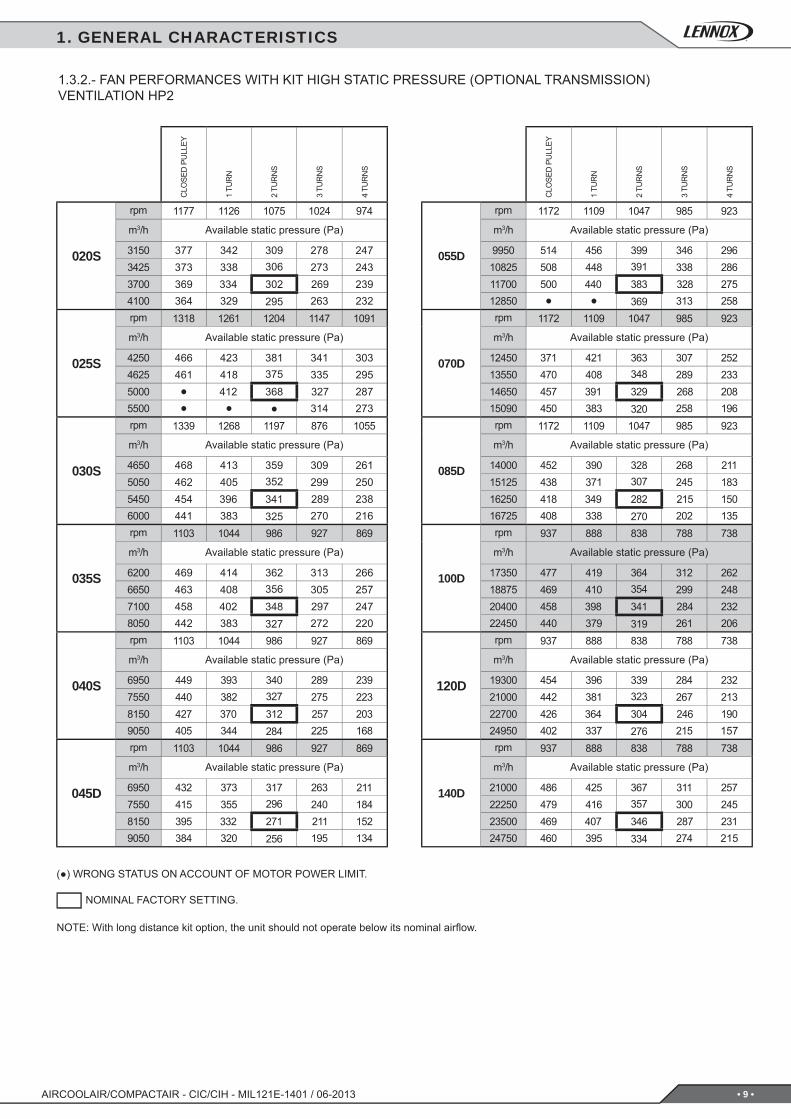
1.3.2.- FAN PERFORMANCES WITH KIT HIGH STATIC PRESSURE (OPTIONAL TRANSMISSION)VENTILATION HP2
CLO
SED
PU
LLEY
1 TU
RN
2 TU
RN
S
3 TU
RN
S
4 TU
RN
S
rpm
m3/h Available static pressure (Pa)
rpm
m3/h Available static pressure (Pa)
rpm
m3/h Available static pressure (Pa)
rpm
m3/h Available static pressure (Pa)
rpm
m3/h Available static pressure (Pa)
rpm
m3/h Available static pressure (Pa)
CLO
SED
PU
LLEY
1 TU
RN
2 TU
RN
S
3 TU
RN
S
4 TU
RN
S
rpm
m3/h Available static pressure (Pa)
rpm
m3/h Available static pressure (Pa)
rpm
m3/h Available static pressure (Pa)
rpm
m3/h Available static pressure (Pa)
rpm
m3/h Available static pressure (Pa)
rpm
m3/h Available static pressure (Pa)
(●) WRONG STATUS ON ACCOUNT OF MOTOR POWER LIMIT.
NOTE: With long distance kit option, the unit should not operate below its nominal airfl ow.
NOMINAL FACTORY SETTING.
• 10 •
020S
1318 1261 1204 1147 1091
3150 483 438 397 357 3193425 478 434 393 353 3163700 474 430 389 349 3124100 469 425 383 343 305
025S
1500 1420 1340 1261 1181
4250 • 550 485 423 3654625 • 545 480 418 3595000 • 541 475 412 3525500 • 532 466 402 339
030S
1500 1420 1340 1261 1181
4650 • 535 469 408 3495050 • 529 463 399 3405450 • 521 455 391 3306000 • 511 443 376 313
035S
1250 1183 1117 1051 985
6200 • 548 483 421 3626650 • 545 478 415 3557100 • 539 472 408 3478050 • 526 456 390 326
040S
1250 1183 1117 1051 985
6950 602 530 463 399 3397550 594 522 453 388 3268150 586 512 442 376 3119050 570 493 421 351 283
045D
1250 1183 1117 1051 985
6950 589 515 446 381 3177550 578 501 430 363 2958150 562 485 411 340 2709050 553 475 400 326 255
055D
1339 1268 1197 1126 1055
9950 689 612 539 471 40610825 683 606 533 464 39811700 677 599 525 457 39012850 670 590 515 444 376
070D
1339 1268 1197 1126 1055
12450 662 582 508 437 37013550 652 573 497 424 35414650 641 561 484 408 33615090 636 555 477 400 328
085D
1339 1268 1197 1126 1055
14000 636 557 478 406 33615125 623 542 464 387 31516250 609 526 445 367 28916725 602 518 436 357 279
100D
1041 986 931 876 820
17350 606 537 469 407 34618875 599 529 461 396 33420400 592 519 451 384 32122450 • 504 433 364 299
120D
1041 986 931 876 820
19300 587 516 447 382 31921000 576 503 433 367 30322700 564 489 418 350 28424950 543 467 393 322 255
140D
1041 986 931 876 820
21000 620 547 477 411 34722250 615 541 471 402 33723500 608 533 462 392 32624750 601 525 451 380 313
AIRCOOLAIR/COMPACTAIR - CIC/CIH - MIL121E-1401 / 06-2013
1. GENERAL CHARACTERISTICS
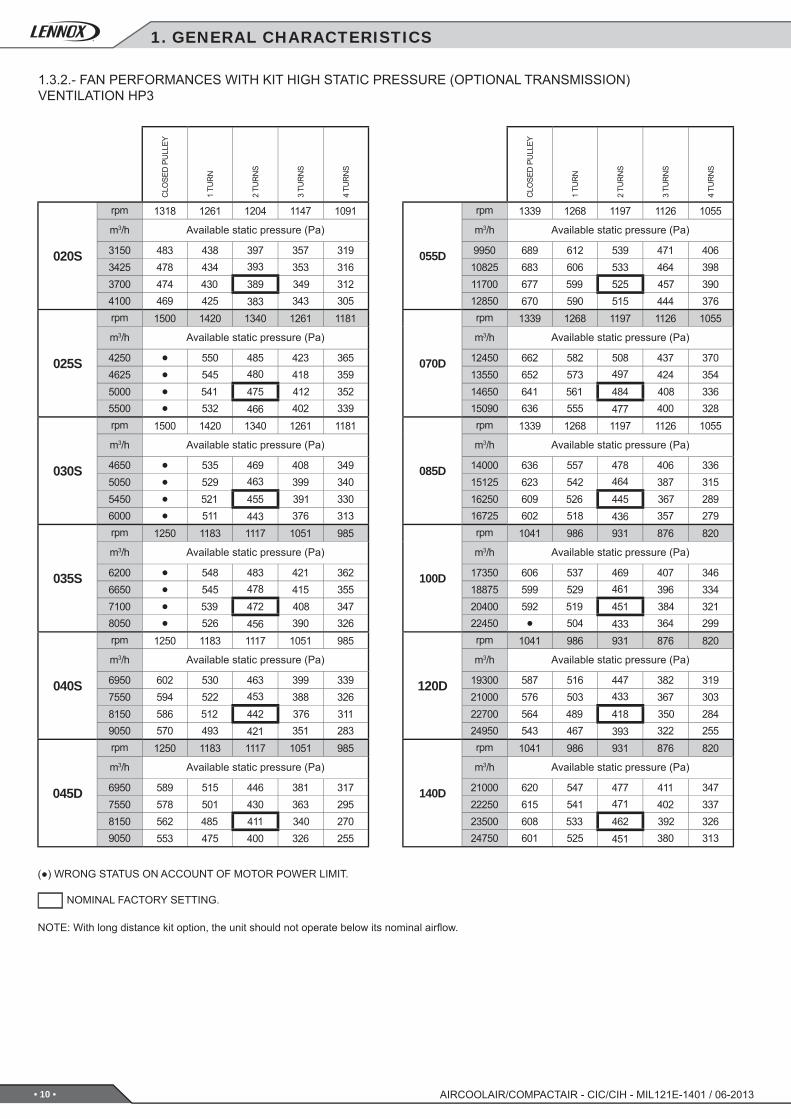
1.3.2.- FAN PERFORMANCES WITH KIT HIGH STATIC PRESSURE (OPTIONAL TRANSMISSION)VENTILATION HP3
CLO
SED
PU
LLEY
1 TU
RN
2 TU
RN
S
3 TU
RN
S
4 TU
RN
S
rpm
m3/h Available static pressure (Pa)
rpm
m3/h Available static pressure (Pa)
rpm
m3/h Available static pressure (Pa)
rpm
m3/h Available static pressure (Pa)
rpm
m3/h Available static pressure (Pa)
rpm
m3/h Available static pressure (Pa)
CLO
SED
PU
LLEY
1 TU
RN
2 TU
RN
S
3 TU
RN
S
4 TU
RN
S
rpm
m3/h Available static pressure (Pa)
rpm
m3/h Available static pressure (Pa)
rpm
m3/h Available static pressure (Pa)
rpm
m3/h Available static pressure (Pa)
rpm
m3/h Available static pressure (Pa)
rpm
m3/h Available static pressure (Pa)
(●) WRONG STATUS ON ACCOUNT OF MOTOR POWER LIMIT.
NOTE: With long distance kit option, the unit should not operate below its nominal airfl ow.
NOMINAL FACTORY SETTING.
• 11 •
020S-025S-030S 035S-040S-045D 055D-070D-085D
2000 2500 2750 3000 3500 4000 6000 7000 8000
160 105 75 210 180 130 260 200 90
100D 120D-140D
13200 14300 15400 16500 13200 14300 15400 16500
230 200 150 50 230 200 150 50
055D
755 715 675 635 595
9950 255 230 207 184 16210825 257 232 208 184 16211700 260 234 210 184 16012850 260 233 207 180 155
070D
755 715 675 635 595
12450 260 235 208 182 15713550 260 233 205 176 15014650 258 228 198 168 14015090 255 225 195 165 135
085D
755 715 675 635 595
14000 260 230 202 173 14515125 255 225 195 165 13516250 250 215 183 153 12016725 • 212 178 145 115
100D
672 636 601 565 529
17350 293 263 234 205 17818875 293 261 232 202 17320400 291 258 227 196 16622450 • 251 218 185 153
120D
766 725 684 644 603
19300 381 343 305 268 232²21000 380 340 300 263 22722700 380 337 297 257 22024750 373 330 287 245 205
140D
766 725 684 644 603
21000 380 340 300 263 22722700 380 337 297 257 22024750 373 330 287 245 205
AIRCOOLAIR/COMPACTAIR - CIC/CIH - MIL121E-1401 / 06-2013
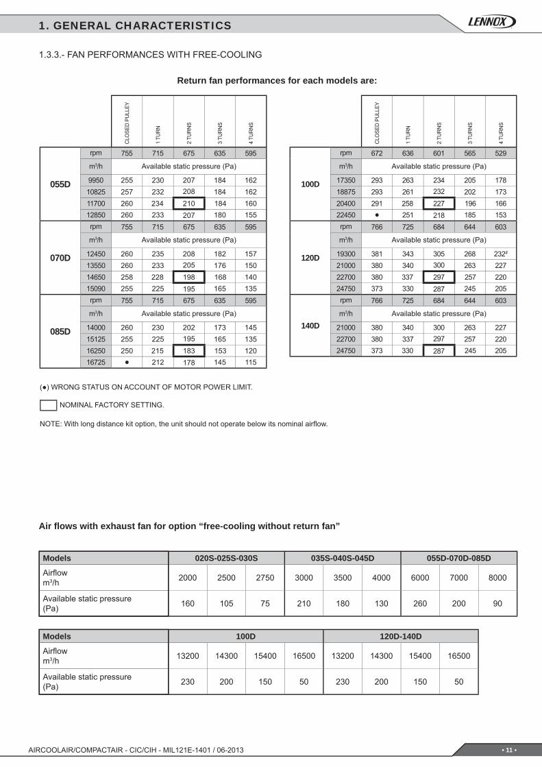
1.3.3.- FAN PERFORMANCES WITH FREE-COOLING
Return fan performances for each models are:
Air fl ows with exhaust fan for option “free-cooling without return fan”
1. GENERAL CHARACTERISTICS
Models
Airfl owm3/h
Available static pressure(Pa)
Models
Airfl owm3/h
Available static pressure(Pa)
CLO
SED
PU
LLEY
1 TU
RN
2 TU
RN
S
3 TU
RN
S
4 TU
RN
S
rpm
m3/h Available static pressure (Pa)
rpm
m3/h Available static pressure (Pa)
rpm
m3/h Available static pressure (Pa)
CLO
SED
PU
LLEY
1 TU
RN
2 TU
RN
S
3 TU
RN
S
4 TU
RN
S
rpm
m3/h Available static pressure (Pa)
rpm
m3/h Available static pressure (Pa)
rpm
m3/h Available static pressure (Pa)
(●) WRONG STATUS ON ACCOUNT OF MOTOR POWER LIMIT.
NOTE: With long distance kit option, the unit should not operate below its nominal airfl ow.
NOMINAL FACTORY SETTING.
• 12 •
346
190
407387
25
400
750213 346 191
603
1005
387 400 407
645
1195
53
18.5
95
104.5
467
455.5
188.
5
455.5 1445
1260
53 140
95
AIRCOOLAIR/COMPACTAIR - CIC/CIH - MIL121E-1401 / 06-2013
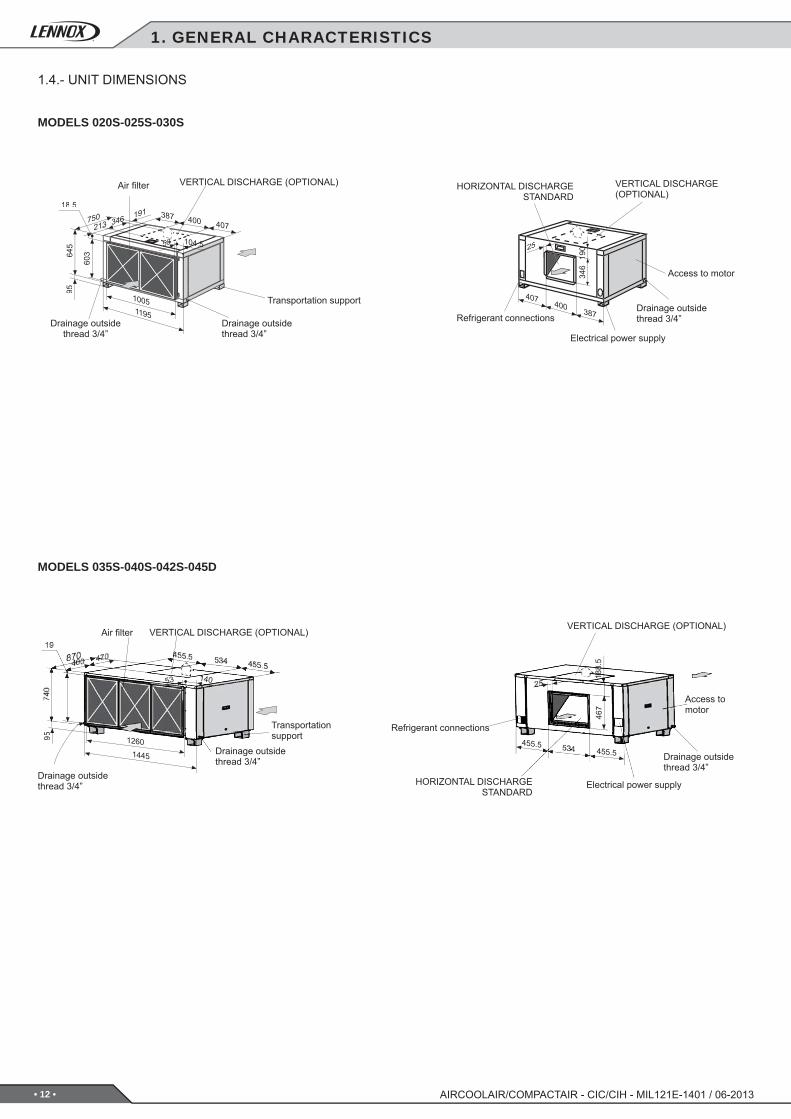
MODELS 020S-025S-030S
MODELS 035S-040S-042S-045D
VERTICAL DISCHARGE (OPTIONAL)
HORIZONTAL DISCHARGE STANDARD
Drainage outsidethread 3/4”Refrigerant connections
Electrical power supply
Access to motor
Drainage outsidethread 3/4”
VERTICAL DISCHARGE (OPTIONAL)
Refrigerant connections
Electrical power supplyHORIZONTAL DISCHARGE STANDARD
Access to motor
Air fi lter VERTICAL DISCHARGE (OPTIONAL)
Drainage outsidethread 3/4”
Drainage outsidethread 3/4”
Transportation support
VERTICAL DISCHARGE (OPTIONAL)
Drainage outsidethread 3/4”
Air fi lter
Transportation support
Drainage outsidethread 3/4”
1.4.- UNIT DIMENSIONS
1. GENERAL CHARACTERISTICS
• 13 •
373
524
203
641603
412603
641
2
53 120
105411
00
26602900
1050
2715244 22555
40
641 603 412603
641
18
34
25
726*
570*
291*
695
740
53 75
95
570
534291
2250
534 321
19570*
55444* 119* 726* 291*
AIRCOOLAIR/COMPACTAIR - CIC/CIH - MIL121E-1401 / 06-2013
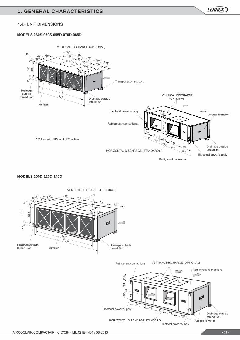
MODELS 060S-070S-055D-070D-085D
MODELS 100D-120D-140D
Air fi lterDrainage outsidethread 3/4”
VERTICAL DISCHARGE (OPTIONAL)
Drainage outsidethread 3/4”
Air fi lter
Drainage outsidethread 3/4”
VERTICAL DISCHARGE (OPTIONAL)
Drainage outside
thread 3/4”
Transportation support
HORIZONTAL DISCHARGE STANDARD
VERTICAL DISCHARGE (OPTIONAL)
Electrical power supply
Electrical power supply
Refrigerant connections
Refrigerant connections
Drainage outsidethread 3/4”
Access to motor
VERTICAL DISCHARGE(OPTIONAL)
Drainage outsidethread 3/4”HORIZONTAL DISCHARGE (STANDARD)
Refrigerant connections
Electrical power supplyAccess to motor
Refrigerant connectionsElectrical power supply
* Values with HP2 and HP3 option.
1. GENERAL CHARACTERISTICS
1.4.- UNIT DIMENSIONS
• 14 •
1 4
2
6
3
5
7
32
1
3
B A
7
3
B A
1 2
AIRCOOLAIR/COMPACTAIR - CIC/CIH - MIL121E-1401 / 06-2013
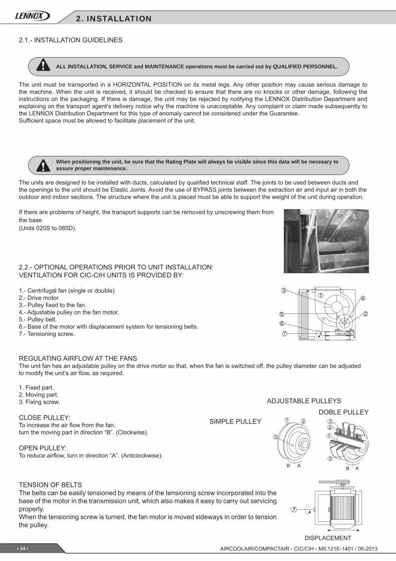
2.1.- INSTALLATION GUIDELINES
2.2.- OPTIONAL OPERATIONS PRIOR TO UNIT INSTALLATION:VENTILATION FOR CIC-CIH UNITS IS PROVIDED BY:
1.- Centrifugal fan (single or double).2.- Drive motor.3.- Pulley fi xed to the fan.4.- Adjustable pulley on the fan motor.5.- Pulley belt.6.- Base of the motor with displacement system for tensioning belts.7.- Tensioning screw.
The unit must be transported in a HORIZONTAL POSITION on its metal legs. Any other position may cause serious damage to the machine. When the unit is received, it should be checked to ensure that there are no knocks or other damage, following the instructions on the packaging. If there is damage, the unit may be rejected by notifying the LENNOX Distribution Department and explaining on the transport agent’s delivery notice why the machine is unacceptable. Any complaint or claim made subsequently to the LENNOX Distribution Department for this type of anomaly cannot be considered under the Guarantee.Suffi cient space must be allowed to facilitate placement of the unit.
ALL INSTALLATION, SERVICE and MAINTENANCE operations must be carried out by QUALIFIED PERSONNEL.
When positioning the unit, be sure that the Rating Plate will always be visible since this data will be necesary to assure proper maintenance.
The units are designed to be installed with ducts, calculated by qualifi ed technical staff. The joints to be used between ducts and the openings to the unit should be Elastic Joints. Avoid the use of BYPASS joints between the extraction air and input air in both the outdoor and indoor sections. The structure where the unit is placed must be able to support the weight of the unit during operation.
If there are problems of height, the transport supports can be removed by unscrewing them from the base(Units 020S to 085D).
REGULATING AIRFLOW AT THE FANSThe unit fan has an adjustable pulley on the drive motor so that, when the fan is switched off, the pulley diameter can be adjusted to modify the unit’s air fl ow, as required.
1. Fixed part.2. Moving part.3. Fixing screw.
CLOSE PULLEY:To increase the air fl ow from the fan, turn the moving part in direction “B”. (Clockwise).
OPEN PULLEY: To reduce airfl ow, turn in direction “A”. (Anticlockwise).
TENSION OF BELTSThe belts can be easily tensioned by means of the tensioning screw incorporated into the base of the motor in the transmission unit, which also makes it easy to carry out servicing properly.When the tensioning screw is turned, the fan motor is moved sideways in order to tension the pulley.
ADJUSTABLE PULLEYS
SIMPLE PULLEYDOBLE PULLEY
DISPLACEMENT
2. INSTALLATION
• 15 •
1m1m
1m
1m
2%
C1
C2
AIRCOOLAIR/COMPACTAIR - CIC/CIH - MIL121E-1401 / 06-2013
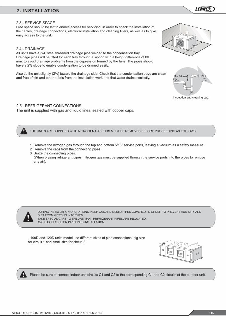
2.3.- SERVICE SPACEFree space should be left to enable access for servicing, in order to check the installation of the cables, drainage connections, electrical installation and cleaning fi lters, as well as to give easy access to the unit.
2.4.- DRAINAGEAll units have a 3/4” steel threaded drainage pipe welded to the condensation tray.Drainage pipes will be fi tted for each tray through a siphon with a height difference of 80 mm. to avoid drainage problems from the depression formed by the fans. The pipes should have a 2% slope to enable condensation to be drained easily.
Also tip the unit slightly (2%) toward the drainage side. Check that the condensation trays are clean and free of dirt and other debris from the installation work and that water drains correctly. UNITMin. 80 mm
Inspection and cleaning cap.
2.5.- REFRIGERANT CONNECTIONSThe unit is supplied with gas and liquid lines, sealed with copper caps.
THE UNITS ARE SUPPLIED WITH NITROGEN GAS. THIS MUST BE REMOVED BEFORE PROCEEDING AS FOLLOWS:
1 Remove the nitrogen gas through the top and bottom 5/16” service ports, leaving a vacuum as a safety measure.2 Remove the caps from the connecting pipes.3 Braze the connecting pipes. (When brazing refrigerant pipes, nitrogen gas must be supplied through the service ports into the pipes to remove
any air).
DURING INSTALLATION OPERATIONS, KEEP GAS AND LIQUID PIPES COVERED, IN ORDER TO PREVENT HUMIDITY AND DIRT FROM GETTING INTO THEM.TAKE SPECIAL CARE TO ENSURE THAT REFRIGERANT PIPES ARE INSULATED.AVOID COLLAPSE ON PIPE LINES INSTALLATION.
- 100D and 120D units model use different sizes of pipe connections: big size for circuit 1 and small size for circuit 2.
Please be sure to connect indoor unit circuits C1 and C2 to the corresponding C1 and C2 circuits of the outdoor unit.
2. INSTALLATION
• 16 •
DS
AS
RS
RS HR/T
CO2
DPT
AS HRT
DIFS
LDRP
DADS
BAC
DS
AS
AS
HR
/T
DPTDIFS
RS
3
BAC
2
DADS
LDRP
CO
2
RSHR/T
6
5
4
0204 x 1,5 mm²
4 x 2,5 mm²+
6 x 1,5 mm²
4 x 4 mm²+
6 x 1,5 mm²
4 x 6 mm²+
6 x 1,5 mm²
4 x 6 mm²+
7 x 1,5 mm²
7 x 1,5mm²
4 x 1,5mm² N/A
025030035
4 x 1,5 mm²4 x 4 mm²
+6 x 1,5 mm²
4 x 6 mm²+
6 x 1,5 mm²
4 x 10 mm²+
6 x 1,5 mm²
4 x 10 mm²+
7 x 1,5 mm²040045055 4 x 1,5 mm²
(STD/HP1)4 x 2,5 mm²(HP2/HP3)
4 x 6 mm²+
6 x 1,5 mm²
3 x 10 mm²+PE+
6 x 1,5 mm²
4 x 16 mm²+
6 x 1,5 mm²
4 x 16 mm²+
7 x 1,5 mm²
4 x 1,5mm²
4 x 1,5mm²070085
1004 x 2,5 mm²(STD/HP1)
2 x (4 x 1,5 mm²) (HP2/HP3) 4 x 10 mm²
+6 x 1,5 mm²
4 x 16 mm²+
6 x 1,5 mm²
4 x 25 mm²+
6 x 1,5 mm²
4 x 25 mm²+
7 x 1,5 mm²4 x 2,5mm²
120 4 x 2,5 mm²(STD/HP1)
2 x (4 x 2,5 mm²) (HP2/HP3)140
AIRCOOLAIR/COMPACTAIR - CIC/CIH - MIL121E-1401 / 06-2013
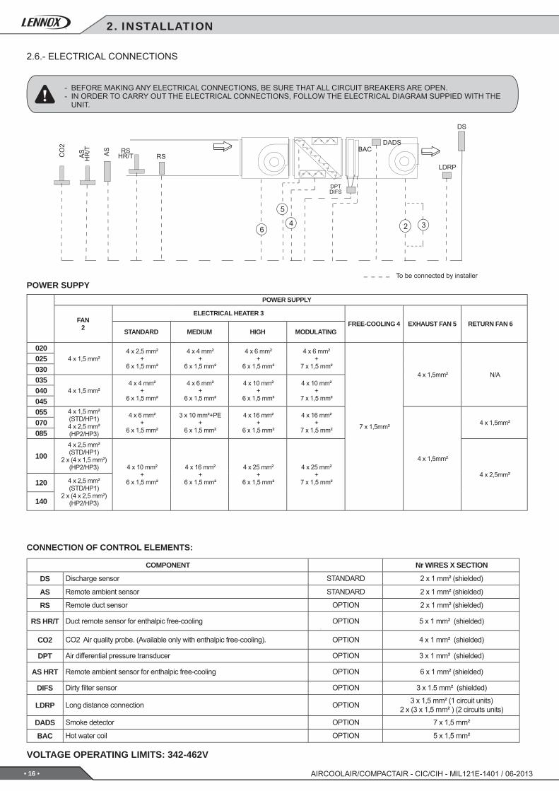
2.6.- ELECTRICAL CONNECTIONS
- BEFORE MAKING ANY ELECTRICAL CONNECTIONS, BE SURE THAT ALL CIRCUIT BREAKERS ARE OPEN.- IN ORDER TO CARRY OUT THE ELECTRICAL CONNECTIONS, FOLLOW THE ELECTRICAL DIAGRAM SUPPIED WITH THE
UNIT.
CONNECTION OF CONTROL ELEMENTS:
VOLTAGE OPERATING LIMITS: 342-462V
To be connected by installerPOWER SUPPY
COMPONENT Nr WIRES X SECTION
Discharge sensor STANDARD 2 x 1 mm² (shielded)
Remote ambient sensor STANDARD 2 x 1 mm² (shielded)
Remote duct sensor OPTION 2 x 1 mm² (shielded)
Duct remote sensor for enthalpic free-cooling OPTION 5 x 1 mm² (shielded)
CO2 Air quality probe. (Available only with enthalpic free-cooling). OPTION 4 x 1 mm² (shielded)
Air differential pressure transducer OPTION 3 x 1 mm² (shielded)
Remote ambient sensor for enthalpic free-cooling OPTION 6 x 1 mm² (shielded)
Dirty fi lter sensor OPTION 3 x 1.5 mm² (shielded)
Long distance connection OPTION 3 x 1,5 mm² (1 circuit units)2 x (3 x 1,5 mm² ) (2 circuits units)
Smoke detector OPTION 7 x 1,5 mm²
Hot water coil OPTION 5 x 1,5 mm²
POWER SUPPLY
FAN2
ELECTRICAL HEATER 3FREE-COOLING 4 EXHAUST FAN 5 RETURN FAN 6
STANDARD MEDIUM HIGH MODULATING
2. INSTALLATION
• 17 •
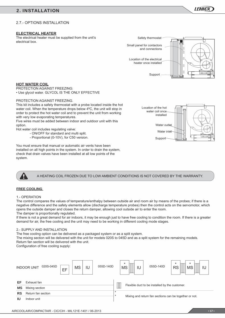
*055D-140D * *055D-140D020S-045D MSEF IUMS IU RS MS IU
EFMSRS
*IU
AIRCOOLAIR/COMPACTAIR - CIC/CIH - MIL121E-1401 / 06-2013
HOT WATER COILPROTECTION AGAINST FREEZING:• Use glycol water. GLYCOL IS THE ONLY EFFECTIVE
PROTECTION AGAINST FREEZING.This kit includes a safety thermostat with a probe located inside the hot water coil. When the temperature drops below 4ºC, the unit will stop in order to protect the hot water coil and to prevent the unit from working with very low evaporating temperatures.Five wires must be added between indoor and outdoor unit with this option.Hot water coil includes regulating valve: - ON/OFF for standard and multi split. - Proportional (0-10V), for C50 version.
You must ensure that manual or automatic air vents have been installed on all high points in the system. In order to drain the system, check that drain valves have been installed at all low points of the system.
Location of the hot water coil once
installed
Water inlet
Water outlet
Support
2.7.- OPTIONS INSTALLATION
ELECTRICAL HEATERThe electrical heater must be supplied from the unit’s electrical box.
Safety thermostat
Small panel for contactors and connections
Location of the electrical heater once installed
Support
A HEATING COIL FROZEN DUE TO LOW AMBIENT CONDITIONS IS NOT COVERED BY THE WARRANTY.
INDOOR UNIT
FREE COOLING
1.- OPERATIONThe control compares the values of temperature/enthalpy between outside air and room air by means of the probes; if there is a negative difference and the safety elements allow (discharge temperature probes) then the control acts on the servomotor, which opens the outside damper and closes the return damper, allowing cool outside air to enter the room.The damper is proportionally regulated.If there is not a great demand for air indoors, it may be enough just to have free cooling to condition the room. If there is a greater demand for air, the free cooling and the unit may need to be working in different cooling mode stages.
2.- SUPPLY AND INSTALLATIONThe free cooling option can be delivered as a packaged system or as a split system.The mixing section will be delivered with the unit for models 020S to 045D and as a split system for the remaining models.Return fan section will be delivered with the unit.Confi guration of free cooling supply:
2. INSTALLATION
Exhaust fanFlexible duct to be installed by the customer.
Mixing section
Return fan section *Mixing and return fan sections can be together or not.
Indoor unit
• 18 •
DM FM
OSHR/T
OS
AS
ASHR/T
DPTCO2
RS
RSHR/T
DSEFM
EFM
3x1.5
4 x 1.5
FM
DMCO2
RSRSHR/T
DPT
DS
OSHR/T
OS
AS
ASHR/T
≥1m
DM EFM FM
AIRCOOLAIR/COMPACTAIR - CIC/CIH - MIL121E-1401 / 06-2013
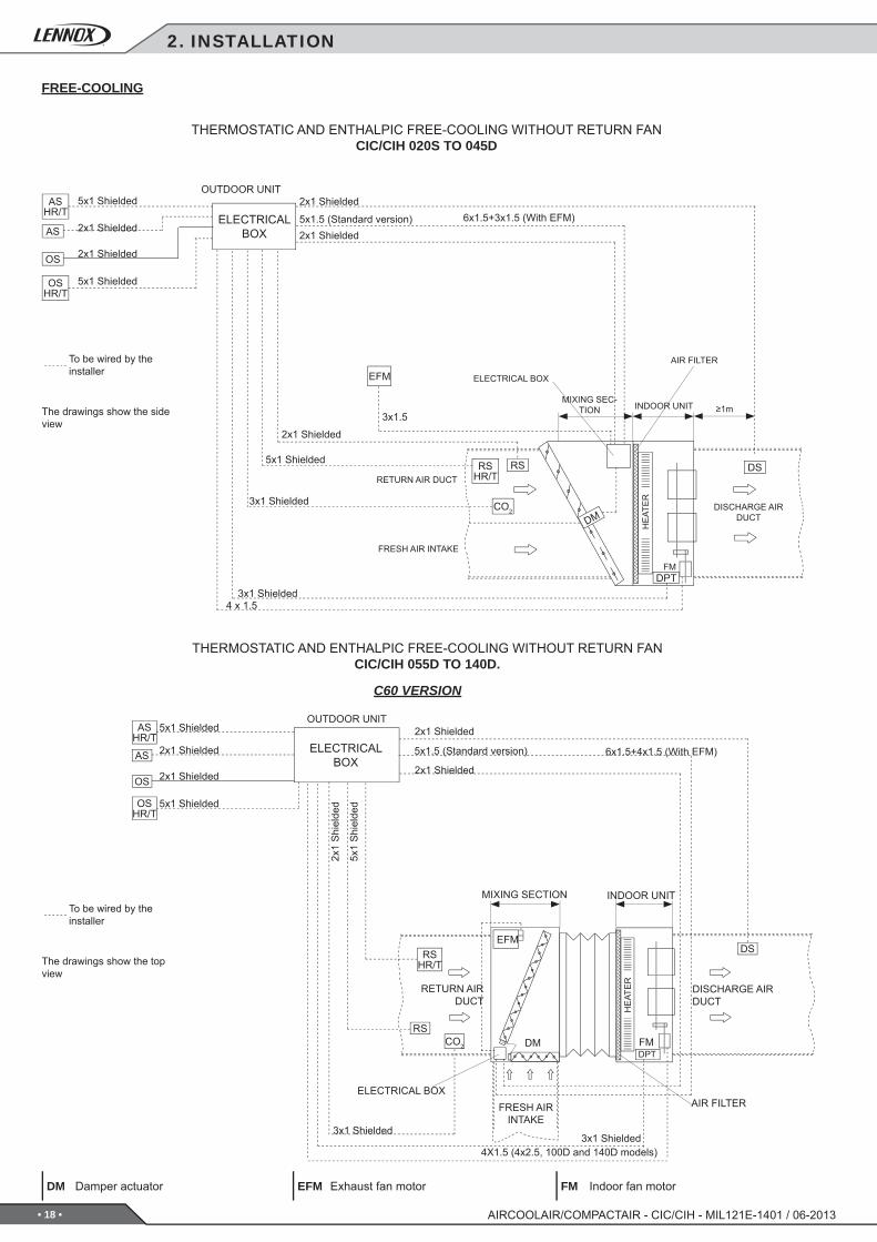
THERMOSTATIC AND ENTHALPIC FREE-COOLING WITHOUT RETURN FANCIC/CIH 020S TO 045D
THERMOSTATIC AND ENTHALPIC FREE-COOLING WITHOUT RETURN FANCIC/CIH 055D TO 140D.
C60 VERSION
FRESH AIR INTAKE
OUTDOOR UNIT
DISCHARGE AIR DUCT
RETURN AIR DUCT
AIR FILTER
HE
ATE
R
MIXING SEC-TION INDOOR UNIT
ELECTRICAL BOX
2x1 Shielded
2x1 Shielded
DISCHARGE AIR DUCT
HE
ATE
R
MIXING SECTION INDOOR UNIT
OUTDOOR UNIT
RETURN AIR DUCT
FRESH AIR INTAKE
ELECTRICALBOX
AIR FILTER
5x1 Shielded
2x1 Shielded
2x1 Shielded
5x1 Shielded
3x1 Shielded3x1 Shielded
2x1
Shi
elde
d
5x1
Shi
elde
d
ELECTRICAL BOX
ELECTRICAL BOX
3x1 Shielded
3x1 Shielded
5x1 Shielded
2x1 Shielded
6x1.5+3x1.5 (With EFM)
5x1 Shielded
2x1 Shielded
2x1 Shielded
5x1 Shielded
To be wired by the installer
To be wired by the installer
The drawings show the side view
The drawings show the top view
5x1.5 (Standard version)2x1 Shielded
2x1 Shielded
4X1.5 (4x2.5, 100D and 140D models)
6x1.5+4x1.5 (With EFM)5x1.5 (Standard version)
2. INSTALLATION
FREE-COOLING
Damper actuator Exhaust fan motor Indoor fan motor
• 19 •
FMRFMCO2
RS
RSHR/T
OSHR/T
OS
AS
ASHR/T
4X2.5
DPT
4X2.5
DM
DS
DM
3x1
DM RFM FM
DS
OS
AS
RS
RS HR/T
CO2
DPT
OS HR/T
AS HR/T
AIRCOOLAIR/COMPACTAIR - CIC/CIH - MIL121E-1401 / 06-2013
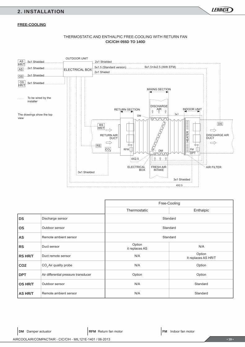
To be wired by the installer
The drawings show the top view
2. INSTALLATION
FREE-COOLING
THERMOSTATIC AND ENTHALPIC FREE-COOLING WITH RETURN FANCIC/CIH 055D TO 140D
FRESH AIR INTAKE
DISCHARGE AIR DUCT
HE
ATE
R
INDOOR UNIT
RETURN AIR DUCT
DISCHARGE AIRRETURN SECTION
AIR FILTER
5x1 Shielded
2x1 Shielded
2x1 Shielded
5x1 Shielded
3x1 Shielded
3x1 Shielded
2x1 Shielded
ELECTRICALBOX
MIXING SECTION
ELECTRICAL BOX2x1 Shieled
6x1.5+4x2.5 (With EFM)5x1.5 (Standard version)
OUTDOOR UNIT
Damper actuator Return fan motor Indoor fan motor
Free-Cooling
Thermostatic Enthalpic
Discharge sensor Standard
Outdoor sensor Standard
Remote ambient sensor Standard
Duct sensor Optionit replaces AS N/A
Duct remote sensor N/A OptionIt replaces AS HR/T
CO2 Air quality probe N/A Option
Air differential pressure transducer Option Option
Outdoor sensor N/A Standard
Remote ambient sensor N/A Standard
• 20 •
740
870
232.5804
113.5
181.5490
478.5
2867
928
312
1626
312
679
38
95
735
1150
2250
22228
2250
A B C D E F G H I J K L M N
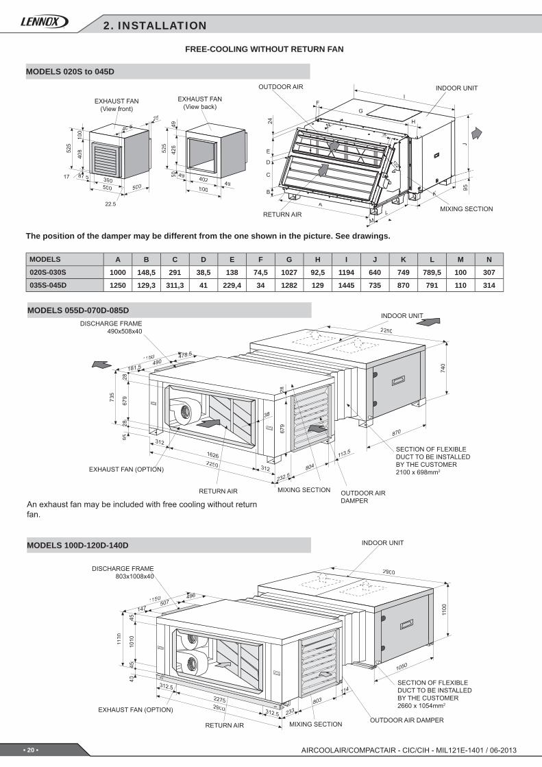
020S-030S 1000 148,5 291 38,5 138 74,5 1027 92,5 1194 640 749 789,5 100 307
035S-045D 1250 129,3 311,3 41 229,4 34 1282 129 1445 735 870 791 110 314
40852
5
100
1
390500
17
22.5
500
4000.55525
49 402 49500
8877.5 5042
649
525
A
C
K
J
L
B
FG
H
I
N
D
E
24
1100
1050
233803
114
147507
496
4510
1045
312.5
2275
312.5
1008
38
40
1100
11150
2900
45
2900
1
AIRCOOLAIR/COMPACTAIR - CIC/CIH - MIL121E-1401 / 06-2013
MODELS 055D-070D-085DINDOOR UNIT
SECTION OF FLEXIBLE DUCT TO BE INSTALLED BY THE CUSTOMER2100 x 698mm2
OUTDOOR AIR DAMPER
MIXING SECTION
DISCHARGE FRAME490x508x40
EXHAUST FAN (OPTION)
RETURN AIR
An exhaust fan may be included with free cooling without return fan.
FREE-COOLING WITHOUT RETURN FAN
The position of the damper may be different from the one shown in the picture. See drawings.
RETURN AIRMIXING SECTION
EXHAUST FAN(View front)
INDOOR UNITOUTDOOR AIR
EXHAUST FAN(View back)
MODELS 020S to 045D
MODELS
MODELS 100D-120D-140D INDOOR UNIT
OUTDOOR AIR DAMPERMIXING SECTION
DISCHARGE FRAME 803x1008x40
EXHAUST FAN (OPTION)
RETURN AIR
SECTION OF FLEXIBLE DUCT TO BE INSTALLED BY THE CUSTOMER2660 x 1054mm2
2. INSTALLATION
• 21 •
740
870
232.5804
113.5
312
312
2867
9
490478.5
181.5
1150
735
2250
679
28
650
2250
1626
9528
1100
1050
233803
114
1008
148
2275
148
4510
10
803214.50
132.50
45 700
1150
2900
40
1100 10
08
38
AIRCOOLAIR/COMPACTAIR - CIC/CIH - MIL121E-1401 / 06-2013
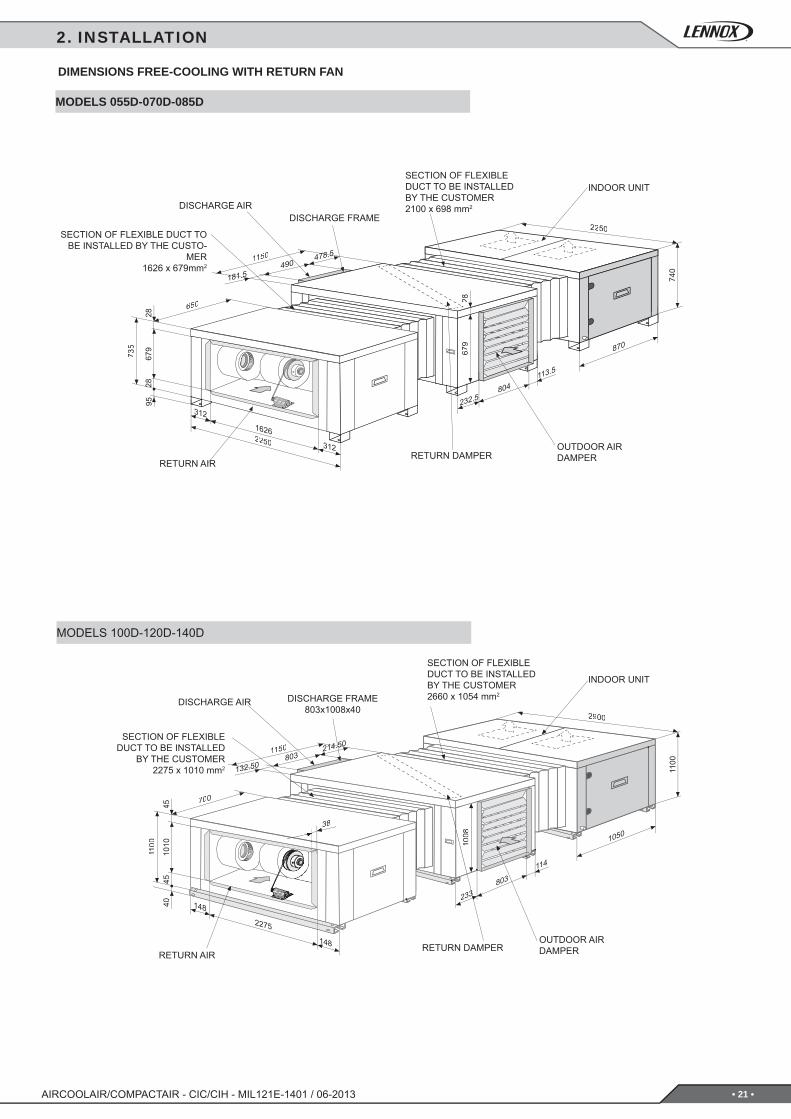
INDOOR UNIT
OUTDOOR AIRDAMPERRETURN DAMPER
RETURN AIR
SECTION OF FLEXIBLE DUCT TO BE INSTALLED BY THE CUSTO-
MER1626 x 679mm2
SECTION OF FLEXIBLE DUCT TO BE INSTALLED BY THE CUSTOMER2100 x 698 mm2
DISCHARGE FRAMEDISCHARGE AIR
DIMENSIONS FREE-COOLING WITH RETURN FAN
MODELS 055D-070D-085D
2. INSTALLATION
MODELS 100D-120D-140D
INDOOR UNIT
SECTION OF FLEXIBLE DUCT TO BE INSTALLED
BY THE CUSTOMER2275 x 1010 mm2
SECTION OF FLEXIBLE DUCT TO BE INSTALLED BY THE CUSTOMER2660 x 1054 mm2DISCHARGE FRAME
803x1008x40DISCHARGE AIR
OUTDOOR AIRDAMPERRETURN DAMPER
RETURN AIR
• 22 • AIRCOOLAIR/COMPACTAIR - CIC/CIH - MIL121E-1401 / 06-2013
3. COMMISSIONING AND OPERATION
3.1.- PRELIMINARY CHECKS BEFORE FIRST OPERATION
1. Check that drainage connections and their fi xtures are secure and that the level of the unit is tipped toward the drain.2. Inspect the condition of the ducts and grilles (grilles are clean and clear of obstructions, no breaks in the duct, etc.).3. Check that the power supply is the same as stated on the Rating Plate and is in accordance with the electrical diagram
for the unit and that cable sizes are correct.4. Check that the electrical connections are tightened onto their terminals and to earth.
Inspect the Air Filter, which should be in its housing and correctly positioned (the metal grille should be facing inwards).5. Check with your hand that the fan turns freely.
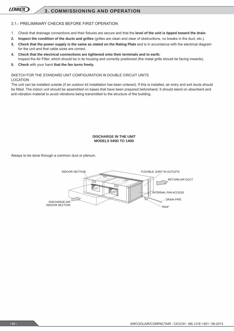
SKETCH FOR THE STANDARD UNIT CONFIGURATION IN DOUBLE CIRCUIT UNITSLOCATIONThe unit can be installed outside (if an outdoor kit installation has been ordered). If this is installed, air entry and exit ducts should be fi tted. The indoor unit should be assembled on bases that have been prepared beforehand. It should stand on absorbent and anti-vibration material to avoid vibrations being transmitted to the structure of the building.
DISCHARGE IN THE UNITMODELS 045D TO 140D
Always to be done through a common duct or plenum.
INDOOR SECTION
DISCHARGE AIRINDOOR SECTION
FLEXIBLE JOINT IN OUTLETS
RETURN AIR DUCT
INTERNAL FAN ACCESS
DRAIN PIPE
TRAP
• 23 •AIRCOOLAIR/COMPACTAIR - CIC/CIH - MIL121E-1401 / 06-2013
4.1.- PREVENTIVE MAINTENANCE
PREVENTIVE MAINTENANCE HELPS TO AVOID COSTLY REPAIRS, SO PERIODIC INSPECTIONS ARE REQUIRED:
GENERAL CONDITION OF THE HOUSING:Fittings, paintwork, damage from knocks, rust spots, levelling and supporting, condition of the shock absorbers, if installed, bolted on panels, etc.
ELECTRICAL CONNECTIONS:Condition of hoses, tightness of screws, earthing, current draw of the compressor and fans and checking that the unit is receiving the correct voltage.
COOLING CIRCUIT:Check that pressure values are correct and that there are no leaks. Check that there is no damage to the pipe insulation, that the state of the batteries is correct and that there are no material clogging the duct and obstructing the air fl ow, etc.
DRAINS:Check that water drains correctly and that the drain trays are clean.
FAN:Check that fans turn freely and in the correct direction without excessive noises.
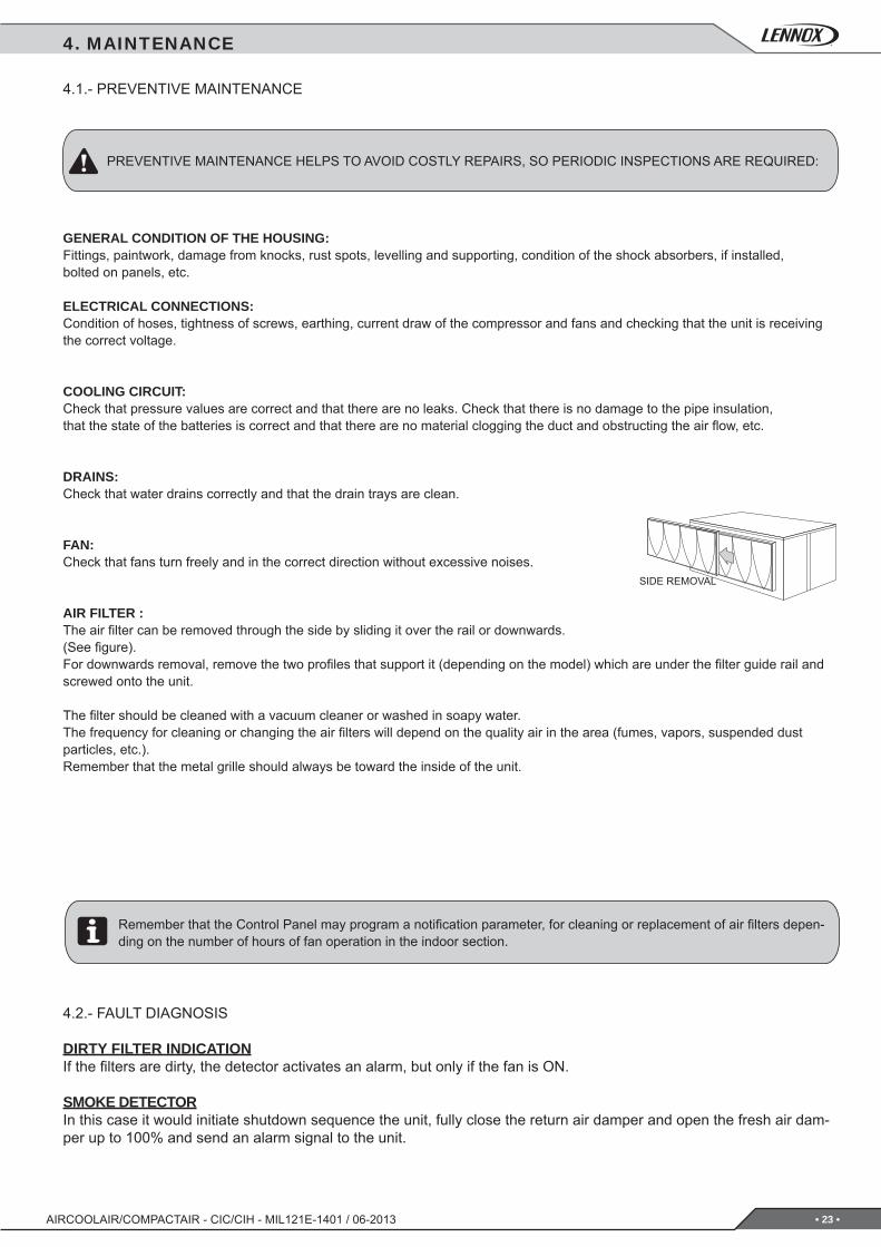
AIR FILTER :The air fi lter can be removed through the side by sliding it over the rail or downwards. (See fi gure).For downwards removal, remove the two profi les that support it (depending on the model) which are under the fi lter guide rail and screwed onto the unit.
The fi lter should be cleaned with a vacuum cleaner or washed in soapy water.The frequency for cleaning or changing the air fi lters will depend on the quality air in the area (fumes, vapors, suspended dust particles, etc.).Remember that the metal grille should always be toward the inside of the unit.
SIDE REMOVAL
Remember that the Control Panel may program a notifi cation parameter, for cleaning or replacement of air fi lters depen-ding on the number of hours of fan operation in the indoor section.
4. MAINTENANCE
4.2.- FAULT DIAGNOSIS
DIRTY FILTER INDICATIONIf the fi lters are dirty, the detector activates an alarm, but only if the fan is ON.
SMOKE DETECTORIn this case it would initiate shutdown sequence the unit, fully close the return air damper and open the fresh air dam-per up to 100% and send an alarm signal to the unit.
lennoxemeia.com
+7 495 626 56 53
+34 902 533 920
+38 044 585 59 10
+44 1604 669 100
+ 32 3 633 3045
+33 1 64 76 23 23
+49 (0) 40 589 6235 13
+ 39 02 495 26 200
+ 31 332 471 800
+48 22 58 48 610
+351 229 066 050
LENNOX DISTRIBUTION
+33 4 72 23 20 00
RUSSIA
SPAIN
UKRAINE
UNITED KINGDOM AND IRELAND
BELGIUM AND LUXEMBOURG
FRANCE
GERMANY
ITALY
NETHERLANDS
POLAND
PORTUGAL
Due to Lennox’s ongoing commitment to quality, the specifi cations, ratings and dimensions are subject to change without notice and without incurring liability.Improper installation, adjustment, alteration, service or maintenance can cause property damage or personal injury.Installation and service must be performed by a qualifi ed installer and servicing agency
SALES OFFICES :
OTHER COUNTRIES :
Translation of original manual
MIL121E-1401 / 06-2013