Embed Size (px)
Citation preview

Ferdinand Schad KGSteigstraße 25-27
D-78600 KolbingenTelephone +49 (0) 74 63 - 980 - 0
Fax +49 (0) 74 63 - 980 - [email protected]
Installation, Mounting and Maintenance
DISA-300
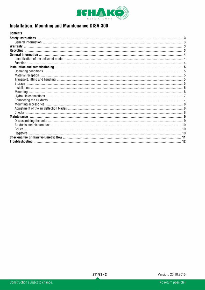
Contents
Construction subject to change. No return possible!
Installation, Mounting and Maintenance DISA-300
Z11/23 - 2 20.10.2015Version:
Safety instructions ...............................................................................................................................3General information ................................................................................................................................................................... 3
Warranty ...........................................................................................................................................3Recycling ..........................................................................................................................................3General information ..............................................................................................................................4
Identification of the delivered model .......................................................................................................................................... 4Function ..................................................................................................................................................................................... 4
Installation and commissioning ................................................................................................................5Operating conditions .................................................................................................................................................................. 5Material reception ...................................................................................................................................................................... 5Transport, lifting and handling ................................................................................................................................................... 5Storage ...................................................................................................................................................................................... 5Installation ................................................................................................................................................................................. 6Mounting ................................................................................................................................................................................... 6Hydraulic connections ............................................................................................................................................................... 7Connecting the air ducts ............................................................................................................................................................ 7Mounting accessories ................................................................................................................................................................ 8Adjustment of the air deflection blades ...................................................................................................................................... 8Checks ....................................................................................................................................................................................... 8
Maintenance ......................................................................................................................................9Disassembling the units ............................................................................................................................................................. 9Air ducts and plenum box ........................................................................................................................................................ 10Grilles ...................................................................................................................................................................................... 10Registers .................................................................................................................................................................................. 10
Checking the primary volumetric flow ....................................................................................................... 11Troubleshooting ................................................................................................................................ 12

Installation, Mounting and Maintenance DISA-300
Safety instructionsPrior to installation and commissioning of this device, pleaseread completely through this manual. Please observe in partic-ular the regulations and operating instructions containing thehazard symbols and safety signs. Their non-observance may re-sult not only in damage to the device but also in light and seri-ous personal injury.If, after reading through the manual, you have further questions,please contact the manufacturer or the local sales office.
General information
SCHAKO shall not give any warranty for damage resulting from:
WarrantyThe device warranty will be for two years starting from thehandover date and shall apply to all production faults. Electriccomponents are excluded from the device warranty. However,they are covered by the corresponding warranty of the relevantmanufacturer Also excluded from the warranty is damage to the device unitcaused by components that are not part of the device itself.The warranty only covers the return and replacement of defec-tive materials.
Recycling
- The inspection, installation, hydraulic connection andcommissioning of the device must be carried out by qual-ified skilled personnel only in compliance with the currentregulations.
- Electric and hydraulic connections and their correct func-tioning are the responsibility of the installer.
- Do not change any control or safety elements without pri-or approval by the manufacturer or the local sales office.
- Improper use caused by ignoring the instructions given inthis manual
- Non-observance of the operating conditions of the device.- Installation and maintenance by personnel without proper
qualification.- Improper use of the device or operation under conditions
not conforming to the manual.- Use of spare parts that are not original spare parts.
It is recommended recycling the components ofthe device at the end of the device service life ascompletely as possible or use them for a differentpurpose.Components that cannot be recycled must beproperly disposed of by an authorized disposalcompany in accordance with current legal regula-tions.
It is recommended keeping this manual at a safe lo-cation after installation and use it for future mainte-nance activities.
Hazard warning
Important information
Safety information
Recycling
Z11/23 - 3
Construction subject to change. No return possible!
20.10.2015Version:

Installation, Mounting and Maintenance DISA-300
General informationIdentification of the delivered modelThe ceiling induction diffuser type DISA-300 is available in fourdifferent nozzle configurations: A, B, C and D, different devicelengths and air directions (-1 or 2 supply air slots).
DISA-300-1 / DISA-300-2
Housing (1): Galvanised sheet steel, with 1 or 2 connectionpipes of DN 98, 123 (standard) and ø 148 mm, horizontal (-H)or vertical (-V) position of the connection pipes.
Register (2): 2-pipe (-H, standard) or 4-pipe register (-HT, op-tional) for cooling and heating. The registers consist of copperpipes 12 mm in thickness, aluminium ribs and a steel frame. Grille (3): Possible designs: perforated sheet grille made of gal-vanised sheet steel (perforated sheet grille models: -SR, -SQ, -RE and -OB) made of extruded aluminium profile (-PA). Bothpainted to RAL 9010 (white, standard).
End pieces (4): Sheet steel painted to RAL 9010. Hydraulic connections (5): Upon customer request, the hy-draulic connection to the registers can be established either on the left-hand (-WS1) or right-hand side (-WS2) of the unit.
FunctionThe primary air (1) supplied from the plenum box induces sec-ondary air in the room (2), which is cooled or heated via the reg-ister (3).The primary air is mixed with the cooled secondary air. Thecombined (4) primary and secondary air flows are supplied tothe room at low velocity via 1 or 2 supply air slots.
Schematic diagram of the mode of operation
Schematic diagram of the jet path
1
2
34
5
Connection pipe positionVertical (-V)
Connection pipe position horizontal (-H)
DISA-...-SR DISA-...-SQ DISA-...-RE DISA-...-OB
DISA-300-1 DISA-300-2
1 1
4 4
33
2 2
DISA-300-1 DISA-300-2
Z11/23 - 4
Construction subject to change. No return possible!
20.10.2015Version:

Installation, Mounting and Maintenance DISA-300
Installation and commissioningOperating conditionsPrior to installation or commissioning of the device, the follow-ing operating conditions must be observed:
Material reception Upon reception of the materials, the components must be care-fully checked, in order to guarantee that no transport damagehas taken place. Moreover, the dimensions, composition andnumber of the identification sticker must be checked as towhether they are as ordered.Identification sticker:
To prevent possible damage during transport, the devices willbe delivered ex works on pallets (that correspond to the partic-ular weight and dimensions) wrapped with tapes and transpar-ent plastic film. It is recommended leaving this protection inplace until the device is commissioned. The openings of thepipes should be closed with dust caps to avoid dust and entry ofdirt.
Transport, lifting and handlingTransport and handling of the unitshall take place in the position inwhich the unit is to be built in lateron, unless expressly stated other-wise on the unit.Transport, unloading and lifting ofthe unit shall take place with thenecessary care and using tools thatare appropriate for the weight anddimensions.
(1) Standard unit: housing + slot + grille and heat exchanger (empty)
StorageIf the device is not installed immediately after its reception, itmust be stored according to the following instructions:
- Coolant or heating fluid: water or glycols (ethylene or propylene) at a concentration below 60%.
- Water inlet temperature: above the dew point up to 80°C(Please note that some quick-action plugs do not work atwater temperatures above 65°C)
- Air inlet temperature: from 2 to 45°C- Max. operating pressure: 8 bar / 125°C
- 2: Number of supply air slots - 2 supply air slots -- H: 2-pipe system- OL: Without air deflection blades- SR: Foldable perforated sheet, - perforation Ø 6 mm -- A: Nozzle configuration - A -- 298: Width -298 mm-- 900: Nominal length - 900 mm -- 1200: Total length -1200 mm-- M: Housing position - centre -- WS1: Hydraulic connection - left -- H: Connection - horizontal -- AS1: Number of connection pipes - 1 connection pipe arranged- 123: Diameter of the connection pipes - 123 mm -- 2E: Model with two end pieces
To prevent deposits and corrosion, the quality of the water for filling the registers mustcomply with regulations VDI 2035 and DIN 50930.
SCHA
KO Ib
eria
, S.L
. - P
ol. I
nd. R
ío G
álle
go, C
/B, n
ave
3 - E
-508
40 S
an M
ateo
de
Gálle
go.Model / Modelo / Modell
DISA-300/2/H/OL/SR/A/298/900/1200/M/WS1/H/AS1/123/2E
Order nr. / Nº Pedido / Auftragsnr: 2198/09 Date / Fecha /Datum: 22/10/2009 Reference / Referencia / Referenz: Sala 1 Hospital Clínico Comments / Observaciones / Bemerkungen:
Read manual of instructions / Lea el manual de instrucciones / Betriebs- und Wartungsvorschriften beachten.Do not drill the machine / Maschine nicht durchbohren / No taladrar la máquinaSpecial attention in the connection nuts-coil / Besondere Vorsicht an der Registerverschraubung/ Especial cuidado en la conexión tuercas-batería .Recycle or arrange the residues according to the current rules / Recicle o gestione los residuos según la normativa vigente. Bitte, entsprechend der gültigen Gezetzgebung recyclen.
NL 900 1200 1500 1800 2100 2400 2700 3000
Weights (1)
(kg) 13 17 20 24 27 31 34 38
- The device must be stored at a dry, clean, safe locationwhere no damage to the device can occur, i.e., outsidecorrosive atmospheric influences.
- Leave the protections attached ex works (film, tapes, pal-lets, etc.) on the device, unless they have already been re-moved beforehand.
- Cover the device with tarpaulins, in order to protect it fromdust, moisture and extreme temperatures.
- Entries, openings and pipes must be hermetically sealedwith dust caps.
Should manufacture-related damage be detectedon the device, please contact your local sales officeprior to installation.
The unit shall only be held in position or moved by holding on to the housing. The weight must notrest on the water connections.SCHAKO cannot be held liable for damage to theunit caused by improper handling or handling notmentioned here, loading or unloading.
Z11/23 - 5
Construction subject to change. No return possible!
20.10.2015Version:

Installation, Mounting and Maintenance DISA-300
InstallationThe ceiling induction diffuser type DISA-300 is particularly suit-able for horizontal installation in low false ceiling heights. Thedevices must not be installed in places with extreme moisture(e.g. laundries or swimming pools), with high dust formation,outdoors or in places subject to explosion hazards. For correct installation, the following instructions must be fol-lowed:
MountingThe induction diffusers are mounted to a load-bearing ceilingconstruction using threaded bars, nuts and an M8 washer.
During mounting the end of the register pipes must be sealed toprotect them from dust and dirt.
Band design
- Make sure that places that are intended as openings for airadmission and air discharge are free of pipes, electric ca-bles, crossbeams, stands, etc.
- Install the unit at a site that has good air quality.- Make sure that wall and ceiling correspond to the weight of
the device and also allow correct mounting of the fasteningelements in the ceiling.
- The installation site must have sufficient space and the nec-essary resources for carrying out mounting and mainte-nance activities of all device components. Make sure thatthe valves are easily accessible.
- The hydraulic pipes should be attached above the device.
NL(mm)
La(mm)
Lc(mm)
V H
1 connecting
piece
2 connecting
pieces900
25
- a a a1200 - a a a1500 - a a a1800 - a a a2100 234 a,b a,c a,b2400 217 a,b a,c a,b2700 206 a,b a,c a,b3000 198 a,b a,c a,b
a ac cb
NL-179
La Lc Lc La
254,
5
- Aligning the devices- Inserting and approaching the connection elements be-
tween the profiles- The connection parts are delivered with the device
For the installation of the device, use adequatetools, devices and materials and observe the safetyregulations and other current regulations.SCHAKO cannot be held liable for damage result-ing from faulty installation or the use of unsuitablefastening devices.
Z11/23 - 6
Construction subject to change. No return possible!
20.10.2015Version:

Installation, Mounting and Maintenance DISA-300
Hydraulic connectionsUpon customer request, the hydraulic connection to the regis-ters can be established either on the left-hand (-WS1) or right-hand side (-WS2) of the unit.DISA-300-1-...-WS1
DISA-300-1-...-WS2
DISA-300-2-...-
Amount of water of the registers:
The connection of the hydraulic connections can be done by sol-dering, pressing (in connection with supporting sleeves) or bymeans of flexible hoses resistant to oxygen diffusion and push-fit systems. The use of flexible hoses is subject to the manufac-turer's specification.
When making the hydraulic con-nections, you have to use suitabletools to avoid excessive tighteningor twisting of the register connec-tions.
When charging the register, make sure by means of on-site ven-tilation devices that no air remains in the hydraulic circuit. If the unit is to be installed at a location having temperatures be-low zero degrees, glycol must be admixed to the coolant in asuitable ratio, to ensure that the freezing point of this liquid al-ways stays below the minimum temperature of the operatingsite. Please note that the use of an antifreeze necessarily resultsin a loss in performance of the register.
Connecting the air ductsThe air ducts are attached by using pipe clamps, fixing lugs orthe like.
Optionally, a rubber lip seal canbe installed on the connectionpipe, to ensure tightness be-tween the device and the pipes.
Water capacity (litres)
NLDISA-300-...-HT
DISA-300-...-HHeating Cooling900 0,2 0,6 0,8
1200 0,3 0,8 11500 0,3 1 1,31800 0,4 1,2 1,62100 0,5 1,4 1,82400 0,5 1,6 2,12700 0,6 1,8 2,43000 0,7 2 2,7
86 4549
11
4586
Heating Cooling
45 86 7
45 8630
Heating Cooling
66 66 289
66 66
Heating Cooling
In order to achieve a uniform cooling capacity, theceiling induction diffusers type DISA-300 shouldbe connected to the cold water distribution systemin parallel. The ceiling induction diffusers type DISA-300 areinduction devices for "dry cooling". To avoid con-densates, the water inlet temperature should behigher than the dew point.
Z11/23 - 7
Construction subject to change. No return possible!
20.10.2015Version:
Installation, Mounting and Maintenance DISA-300
Mounting accessoriesValves and actuatorsValves and actuators shall not be installed ex works. During installation the manufacturer's specifications must be ob-served.
Temperature controlsThe temperature controls are mounted in accordance with theselected model. This is why the instructions enclosed with eachmodel must be followed. However, in order to achieve optimummeasurement by the sensors, the following basic informationshould be observed:
Condensate monitorThe installation of a condensate monitor depends on the select-ed model. Please follow the instructions enclosed with each model.
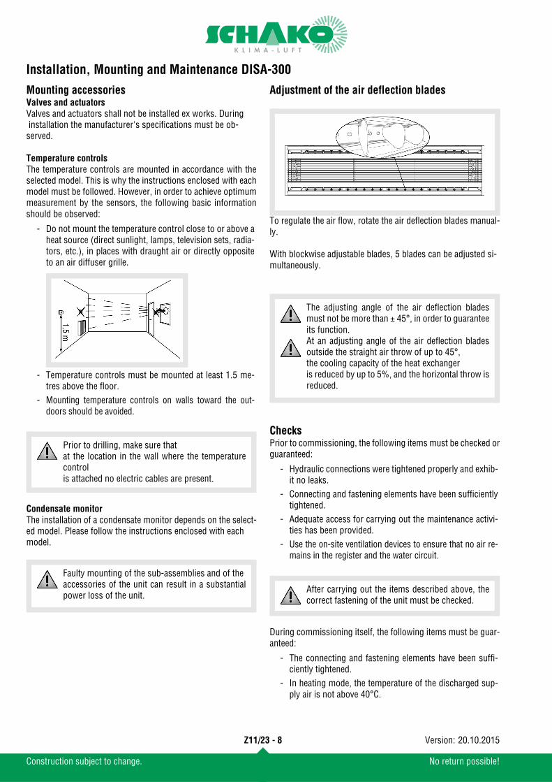
Adjustment of the air deflection blades
To regulate the air flow, rotate the air deflection blades manual-ly.
With blockwise adjustable blades, 5 blades can be adjusted si-multaneously.
ChecksPrior to commissioning, the following items must be checked orguaranteed:
During commissioning itself, the following items must be guar-anteed:
- Do not mount the temperature control close to or above aheat source (direct sunlight, lamps, television sets, radia-tors, etc.), in places with draught air or directly oppositeto an air diffuser grille.
- Temperature controls must be mounted at least 1.5 me-tres above the floor.
- Mounting temperature controls on walls toward the out-doors should be avoided.
Prior to drilling, make sure that at the location in the wall where the temperaturecontrol is attached no electric cables are present.
Faulty mounting of the sub-assemblies and of the accessories of the unit can result in a substantialpower loss of the unit.
- Hydraulic connections were tightened properly and exhib-it no leaks.
- Connecting and fastening elements have been sufficientlytightened.
- Adequate access for carrying out the maintenance activi-ties has been provided.
- Use the on-site ventilation devices to ensure that no air re-mains in the register and the water circuit.
- The connecting and fastening elements have been suffi-ciently tightened.
- In heating mode, the temperature of the discharged sup-ply air is not above 40°C.
The adjusting angle of the air deflection bladesmust not be more than ± 45°, in order to guaranteeits function.At an adjusting angle of the air deflection bladesoutside the straight air throw of up to 45°, the cooling capacity of the heat exchanger is reduced by up to 5%, and the horizontal throw isreduced.
After carrying out the items described above, thecorrect fastening of the unit must be checked.
Z11/23 - 8
Construction subject to change. No return possible!
20.10.2015Version:
Installation, Mounting and Maintenance DISA-300
MaintenanceFor reasons of safety, the power supply and hydraulic circuitmust be disconnected prior to any maintenance activity.If the unit was operated in heating mode, you have to wait untilthe register has cooled down.
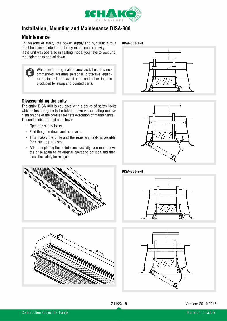
Disassembling the unitsThe entire DISA-300 is equipped with a series of safety lockswhich allow the grille to be folded down via a rotating mecha-nism on one of the profiles for safe execution of maintenance.The unit is dismounted as follows:
DISA-300-1-H
DISA-300-2-H
- Open the safety locks.- Fold the grille down and remove it.- This makes the grille and the registers freely accessible
for cleaning purposes.- After completing the maintenance activity, you must move
the grille again to its original operating position and thenclose the safety locks again.
When performing maintenance activities, it is rec-ommended wearing personal protective equip-ment, in order to avoid cuts and other injuriesproduced by sharp and pointed parts.
Z11/23 - 9
Construction subject to change. No return possible!
20.10.2015Version:
Installation, Mounting and Maintenance DISA-300
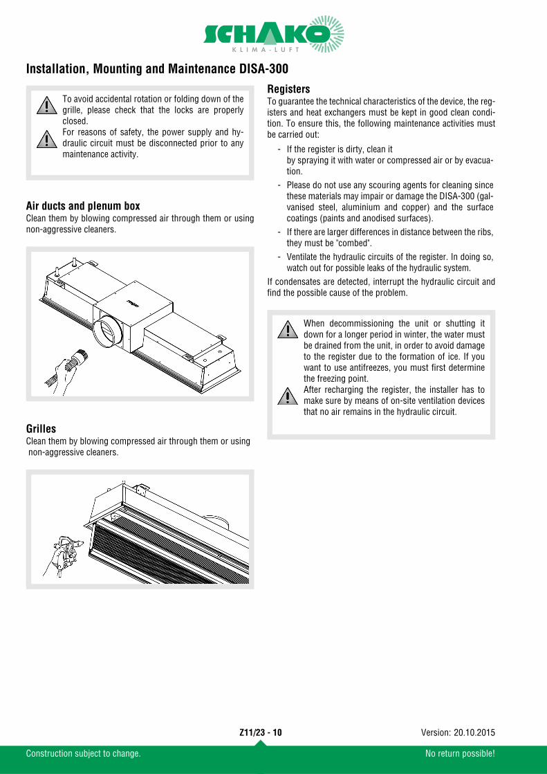
Air ducts and plenum boxClean them by blowing compressed air through them or usingnon-aggressive cleaners.
GrillesClean them by blowing compressed air through them or using non-aggressive cleaners.
RegistersTo guarantee the technical characteristics of the device, the reg-isters and heat exchangers must be kept in good clean condi-tion. To ensure this, the following maintenance activities mustbe carried out:
If condensates are detected, interrupt the hydraulic circuit andfind the possible cause of the problem.
To avoid accidental rotation or folding down of thegrille, please check that the locks are properlyclosed.For reasons of safety, the power supply and hy-draulic circuit must be disconnected prior to anymaintenance activity. - If the register is dirty, clean it
by spraying it with water or compressed air or by evacua-tion.
- Please do not use any scouring agents for cleaning sincethese materials may impair or damage the DISA-300 (gal-vanised steel, aluminium and copper) and the surfacecoatings (paints and anodised surfaces).
- If there are larger differences in distance between the ribs,they must be "combed".
- Ventilate the hydraulic circuits of the register. In doing so,watch out for possible leaks of the hydraulic system.
When decommissioning the unit or shutting itdown for a longer period in winter, the water mustbe drained from the unit, in order to avoid damageto the register due to the formation of ice. If youwant to use antifreezes, you must first determinethe freezing point.After recharging the register, the installer has tomake sure by means of on-site ventilation devicesthat no air remains in the hydraulic circuit.
Z11/23 - 10
Construction subject to change. No return possible!
20.10.2015Version:

Installation, Mounting and Maintenance DISA-300
Checking the primary volumetric flowThe supplied primary volumetric flow can be simply checked bychecking the static pressure with a Pa meter and the measuringtube available from us as accessory. To this end, one end of the measuring tube fitted with a rubbercap is pressed against the air outlet of one of the nozzles at theprimary air plenum box (see drawing) and the other end is con-nected to the hose connection of a Pa meter.
The values read on the meter and the following formula can beused to determine the volumetric flow:
V [l/s] = Primary air flowPs [Pa] = Static pressure The K value is taken from the following table:
Nozzle configuration A Nozzle configuration B
NL (mm)
Nozzle config-uration
900 1200 1500 1800 2100 2400 2700 3000
A 0,42 0,62 0,79 0,99 1,16 1,32 1,51 1,69
B 0,71 1,06 1,35 1,69 1,98 2,27 2,59 2,90
C 1,32 1,96 2,50 3,14 3,68 4,21 4,80 5,39
D 1,97 2,92 3,72 4,67 5,48 6,28 7,15 8,03
V K Ps=
The Pa meter is not included in the delivery.
Vzu (m3/h)0 20 40 60 80 100 200 300
020
4060
8010
020
030
0
�P (Pa.)
900-
A12
00-A
1500
-A18
00-A
2100
-A24
00-A
2700
-A30
00-A
900-
B
1200
-B15
00-B
1800
-B21
00-B
2400
-B27
00-B
3000
-B
Vzu (m3/h)0 20 40 60 80 100 200 300
020
4060
8010
020
030
0
�P (Pa.)
Z11/23 - 11
Construction subject to change. No return possible!
20.10.2015Version:

Installation, Mounting and Maintenance DISA-300
Nozzle configuration C Nozzle configuration DTroubleshooting
Vzu (m3/h)0 20 40 60 80 100 200 300
020
4060
8010
020
030
0
�P (Pa.)
900-
C
1200
-C
1500
-C
1800
-C
2100
-C
2400
-C
2700
-C
3000-C
Vzu (m3/h)0 20 40 60 80 100 200 3000
2040
6080
100
200
300
�P (Pa.)
900-
D
1200
-D
1500
-D
1800
-D
2100-D
2400-D
2700-D
3000-D
Problem Possible cause Solution
The unit does not cool or heat suffi-ciently
Air inlet and outlet of the inner unit clogged Remove foreign material and clean the unit
Air in the interior of the register Ventilation of the hydraulic systemPlease inform the installer
Installed unfavourable or malfunctions at the temperaturecontrol or sensor Install thermostat in a different place
Clogging in the interior of the unit or at the air inletRemove foreign material and clean the inte-rior of the unit
The unit is losing waterCondensate in the register Modify the register water inlet temperatureThe water circuit of the register is leaking
Please inform the installerRegister damagedIncorrect valve or hydraulic connection
The unit is working with too muchnoise
The air intake or air blow openings or the lines are clogged. Remove foreign material and clean the unitLoose screws and fastening elements Tighten screws
Foreign material or dirt on register surface Remove foreign material by careful brushing
Z11/23 - 12
Construction subject to change. No return possible!
20.10.2015Version: