Embed Size (px)
Citation preview
min. 60
55
min. 100
min. 80
Mounting position (mm)
Ascon Tecnologic S.r.l.via Indipendenza 56, 27029 - Vigevano (PV)Tel.: +39 0381 69871, Fax: +39 0381 698730www.ascontecnologic.com
InstallationManual
Contents- General description- Accessories- Installation- Electrical connections- Electric safety
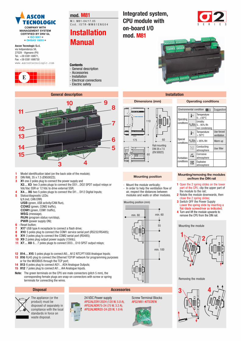
1 Model identification label (on the back side of the module);2 DIN RAIL 35 x 7.5 (EN50022);3 X1 one 2 poles plug to connect the power supply and
X2... X3 two 3 poles plugs to connect the DO1...DO2 SPDT output relays or Vdc/Vac SSR or 12 Vdc to drive external SSR;
4 X4... X6 two 5 poles plugs to connect the DI1... DI12 Digital Inputs;5 Status/diagnostic LEDs:
L1 (red, CAN ERR) USB (green, USB activity/CAN Run), COM2 (green, COM2 traffic), COM1 (green, COM1 traffic), MSG (message), RUN (program status run/stop), PWR (power supply ON);
6 - Reset button;7 X17 USB type A receptacle to connect a flash drive;8 X10 5 poles plug to connect the COM1 service serial port (RS232/RS485);9 X11 3 poles plug to connect the COM2 serial port (RS485);10 X9 2 poles plug output power supply (15Vdc);11 X7... X8 6... 7 poles plugs to connect DO3... D10 SPST output relays;
General description
Accessories
Installation
24 VDC Power supplyAPS2ALEDR12024 (120 W, 5.0 A), APS2ALNDR75-24 (75 W, 3.2 A),APS2ALMDR20-24 (20 W, 1.0 A)
1 Open the 2 spring slides on the lower part of the CPU, clip the upper part of the module to the rail;
2 Rotate the module downwards, then close the 2 spring slides;
3 Switch OFF the Power Supply Lower the spring slide by inserting a flat-blade screwdriver as indicated;
4 Turn and lift the module upwards to remove the CPU from the DIN rail.
Dimensions (mm)
Mounting the module
- Mount the module vertically;- In order to help the ventilation flow of
air, respect the distances between modules and walls or other modules.
Mounting positionMounting/removing the modules
on/from the DIN rail
Removing the module
Operating conditions
Integrated system,CPU module with on-board I/Omod. M81
mod. M81M. I . M81-04 /17 . 05C o d . I S T R - M M 8 1 E N G 0 4
Rail mounting DIN 35 x 7.5(EN 50022)
110
175
60
60
Environmental conditionB Suggestion
Operating conditions
TTemperature 0...+50°C
%RhUmidity: 5... 95% Rh non condensing
Special conditions
TTemperature > 50°C
Use forced ventilation
%Rh > 95% RH Warm up
PConducting atmosphere
Use filter
Forbidden conditionsC
Corrosive atmosphere
EExplosive atmosphere
1 2
3 4
3 4
1415
11
1213
56
7
9108
12 X14... X15 5 poles plugs to connect AI5... AI12 NTC/PT1000 Analogue Inputs;13 X16 RJ45 plug to connect the Ethernet TCP/IP network for programming purposes
or for the MODBUS through the TCP port;14 X13 6 poles plug to connect AO1... AO4 Analogue Outputs;15 X12 7 poles plug to connect AI1... AI4 Analogue Inputs.
Note: The green terminals on the CPU are male connectors (pitch 5 mm), the corresponding female plugs are snap-on connectors with screw or spring terminals for connecting the wires.
E
Screw Terminal BlocksAPS2/M81-kITSCREW
Disposal
The appliance (or the product) must be disposed of separately in compliance with the local standards in force on waste disposal.
Electrical connections
M81
X1 Supply24 VAC/VDC C NO NC
X2 DO1C NO NC
X2 DO2M DI1 DI2 DI3 DI4
X4
(CAN)ERR RUN
M DI5 DI6 DI7 DI8X5
M DI9 DI10 DI11 DI12X6
M AI1 AI2 AI3 AI4 +5 +12X12
AO1 AO2 M M AO3 AO4 L1 USB COM1 MSG RUN PWRX13
� �
C AI5 AI6 AI7 AI8X14
C AI9 AI10 AI11 AI12X15
ETHERNETX16
USBX17
C DO3 DO4X7
C DO5 DO6 C DO7 DO8X8
C DO9 DO10X9
M +15X10 COM1
Rx Tx GND D+X11 COM2
D- D+ D- GND
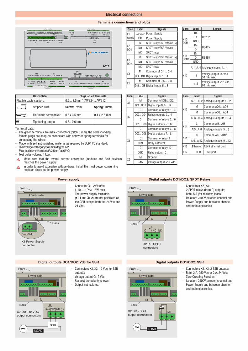
Terminals connections and plugs
Lower side
Front
X1 Power Supply connector
Back
Vac/Vdc
Power supply
- Connector X1: 24Vac/dc (–10...+10%), 15W max.;
- The power supply terminals (X1-1 and X1-2) are not polarized as the CPU acceps both the 24 Vac and 24 Vdc.
Conn. Label Signals
X1 Supply
24 Vac/Vdc
Power Supply
Power Supply
X2 DO1
C SPDT relay/SSR Vac/dc (+)
NO SPDT relay/SSR Vac/dc (-)
NC SPDT relay
X3 DO2
C SPDT relay/SSR Vac/dc (+)
NO SPDT relay/SSR Vac/dc (-)
NC SPDT relay
X4M Common of DI1... DI4
DI1... DI4 Digital inputs 1... 4
X5M Common of DI5... DI8
DI5... DI8 Digital inputs 5... 8
Conn. Label Signals
X6M Common of DI9... DI2
DI9... DI12 Digital inputs 9... 12
X7
C Common of relays 3... 4
DO3... DO4 Relays outputs 3... 4
C Common of relays 5... 6
DO5... DO6 Digital outputs 5... 6
X8
C Common of relays 7... 8
DO7... DO8 Digital outputs 7... 8
C Common of relay 9
DO9 Relay output 9
C Common of relay 10
DO10 Relay output 10
X9M Ground
+15 Voltage output +15 Vdc
Conn. Label Signals
X10 COM1
RXRS232TX
GNDD+
RS485D-
X11 COM2
D+RS485D-
GND
X12
AI1...AI4 Analogue inputs 1... 4
+5 Voltage output +5 Vdc, 30 mA max.
+12 Voltage output +12 Vdc, 80 mA max.
Lower side
Front
X2, X3 SPDT connectors
C NCNO
Back
Digital outputs DO1/DO2: SPDT Relays
- Connectors X2, X3: 2 SPDT relays (form C) outputs;
- Rate: 5 A (for resistive loads);- Isolation: 2500V beween channel and
Power Supply and between channel and main electronics.
Conn. Label Signals
X13
AO1... AO2 Analogue outputs 1... 2
M Common AO1... AO2
M Common AO3... AO4
AO3...AO4 Analogue outputs 3... 4
X14C Common AI5...AI8
AI5...AI8 Analogue inputs 5... 8
X15C Common AI9...AI12
AI9...AI12 Analogue inputs 9... 12
X16 Ethernet RJ45 ethernet port
X17 USB USB port
Description Plugs of all terminalsFlexible cable section: 0.2... 2.5 mm² (AWG24... AWG12)
L Stripped wire Screw: 7mm Spring: 10mm
Flat blade screwdriver 0.6 x 3.5 mm 0.4 x 2.5 mm
Tightening torque 0.5... 0.6 Nm -
Technical data:- The green terminals are male connectors (pitch 5 mm), the corresponding
female plugs are snap-on connectors with screw or spring terminals for connecting the wires;
- Made with self extinguishing material as required by UL94 V0 standard;- Overvoltage cathegory/pollution degree II/2;- Max. load current/section 8A/2.5mm² at 65°C;- Test pulse voltage: 4 kVp.
A Make sure that the overall current absorption (modules and field devices)
matches the power supply;
A In order to avoid excessive voltage drops, install the most power consuming
modules closer to the power supply.
Lower side
Front
X2, X3 - 12 VDCoutput connectors
C (+) NO (-)Back
LOAD
SSR
Digital outputs DO1/DO2: Vdc for SSR
- Connectors X2, X3: 12 Vdc for SSR outputs;
- Voltage output 0/12 Vdc;- Respect the polarity shown;- Output not isolated.
Lower side
Front
X2, X3 - SSRoutput connectors
C NO
Back
LOAD
Digital outputs DO1/DO2: SSR
- Connectors X2, X3: 2 SSR outputs;- Rate: 2 A, 250 Vac or 2 A, 24 Vdc;- Zero Crossing Function;- Isolation: 2500V beween channel and
Power Supply and between channel and main electronics.
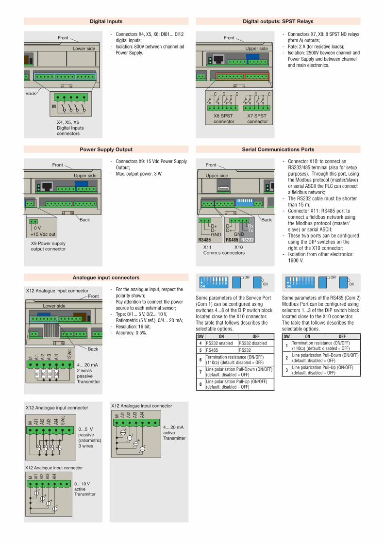
Power Supply Output
- Connectors X9: 15 Vdc Power Supply Output;
- Max. output power: 3 W.Upper side
Front
Back
X9 Power supply output connector
0 V+15 Vdc out
Serial Communications Ports
- Connector X10: to connect an RS232/485 terminal (also for setup purposes). Through this port, using the Modbus protocol (master/slave) or serial ASCII the PLC can connect a fieldbus network;
- The RS232 cable must be shorter than 15 m;
- Connector X11: RS485 port to connect a fieldbus network using the Modbus protocol (master/slave) or serial ASCII;
- These two ports can be configured using the DIP switches on the right of the X10 connector;
- Isolation from other electronics: 1600 V.
Upper side
Front
Back
X11 Comm.s connectors
RxTx
X10
D+D-GND
D-D+
RS485 RS485 RS232GND
Some parameters of the Service Port (Com 1) can be configured using switches 4...8 of the DIP switch block located close to the X10 connector.The table that follows describes the selectable options.SW ON OFF4 RS232 enabled RS232 disabled
5 RS485 RS232
6Termination resistance (ON/OFF) (110Ω) (default: disabled = OFF)
7Line polarization Pull-Down (ON/OFF) (default: disabled = OFF)
8Line polarization Pull-Up (ON/OFF) (default: disabled = OFF)
Some parameters of the RS485 (Com 2) Modbus Port can be configured using selectors 1...3 of the DIP switch block located close to the X10 connector.The table that follows describes theselectable options.SW ON OFF
1Termination resistance (ON/OFF) (110Ω) (default: disabled = OFF)
2Line polarization Pull-Down (ON/OFF) (default: disabled = OFF)
3Line polarization Pull-Up (ON/OFF) (default: disabled = OFF)
Analogue input connectors
Lower side
FrontX12 Analogue input connector
Back
M AI1
AI2
AI3
AI4
12Vd
c
4... 20 mA 2 wirespassive Transmitter
4... 20 mAactive Transmitter
X12 Analogue input connector
M AI1
AI2
AI3
AI4
-+
-+
-+
-+
X12 Analogue input connector
M AI1
AI2
AI3
AI4
5Vdc
0...5 V passive (ratiometric)3 wires
0... 10 Vactive Transmitter
X12 Analogue input connector
M AI1
AI2
AI3
AI4
-+
-+
-+
-+
- For the analogue input, respect the polarity shown;
- Pay attention to connect the power source to each external sensor;
- Type: 0/1... 5 V, 0/2... 10 V, Ratiometric (5 V ref.), 0/4... 20 mA;
- Resolution: 16 bit;- Accuracy: 0.5%.
Lower side
Front
X4, X5, X6 Digital Inputs connectors
Back
M
Digital Inputs
- Connectors X4, X5, X6: DI01... DI12 digital inputs;
- Isolation: 800V between channel ad Power Supply.
Digital outputs: SPST Relays
- Connectors X7, X8: 8 SPST NO relays (form A) outputs;
- Rate: 2 A (for resistive loads);- Isolation: 2500V beween channel and
Power Supply and between channel and main electronics.
Upper side
CCC C C
Front
X7 SPST connector
X8 SPST connector
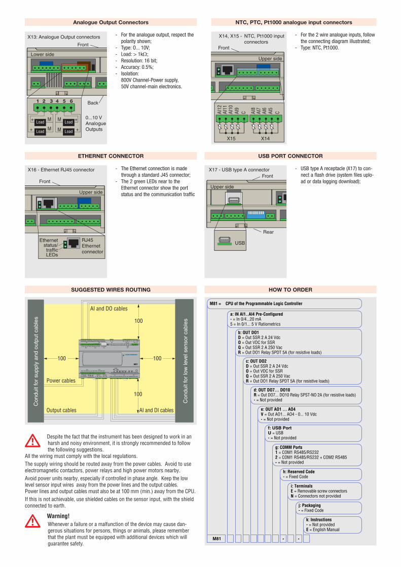
ETHERNET CONNECTOR
- The Ethernet connection is made through a standard J45 connector;
- The 2 green LEDs near to the Ethernet connector show the port status and the communication traffic Upper side
Front
X16 - Ethernet RJ45 connector
RJ45Ethernet connector
Ethernetstatus/trafficLEDs
USB PORT CONNECTOR
- USB type A receptacle (X17) to con-nect a flash drive (system files uplo-ad or data logging download);
Upper side
FrontX17 - USB type A connector
Rear
USB
SUGGESTED WIRES ROUTING
M81
X1 Supply24 VAC/VDC C NO NC
X2 DO1C NO NC
X2 DO2M DI1 DI2 DI3 DI4
X4
(CAN)EPR RUN
M DI5 DI6 DI7 DI8X5
M DI9 DI10 DI11 DI12X6
M AI1 AI2 AI3 AI4 +5 +12X12
AO1 AO2 M M AO3 AO4 L1 USB MSG COM1MSG RUN PWRX13
� �
C AI5 AI6 AI7 AI8X14
C AI9 AI10 AI11 AI12X15
ETHERNETX16
USBX17
C DO3 DO4X7
C DO5 DO6 C DO7 DO8X8
C DO9 DO10X9
M +15X10 COM1
Rx Tx GND D+X11 COM2
D- D+ D- GND
100 100
100
100
Con
duit
for
low
leve
l sen
sor
cabl
es
Con
duit
for
supp
ly a
nd o
utpu
t cab
les
Output cables
Power cables
AI and DI cables
AI and DO cables
ADespite the fact that the instrument has been designed to work in an harsh and noisy environment, it is strongly recommended to follow the following suggestions.
All the wiring must comply with the local regulations. The supply wiring should be routed away from the power cables. Avoid to use electromagnetic contactors, power relays and high power motors nearby.Avoid power units nearby, especially if controlled in phase angle. Keep the low level sensor input wires away from the power lines and the output cables. Power lines and output cables must also be at 100 mm (min.) away from the CPU.If this is not achievable, use shielded cables on the sensor input, with the shield connected to earth.
AWarning!Whenever a failure or a malfunction of the device may cause dan-gerous situations for persons, things or animals, please remember that the plant must be equipped with additional devices which will guarantee safety.
HOW TO ORDER
f: USB PortU = USB- = Not provided
M81 -
M81 = CPU of the Programmable Logic Controller
d: OUT DO7... DO10R = Out DO7... DO10 Relay SPST-NO 2A (for resistive loads)- = Not provided
e: OUT AO1 ... AO4V = Out AO1... AO4 - 0... 10 Vdc- = Not provided
g: COMM Ports1 = COM1 RS485/RS2322 = COM1 RS485/RS232 + COM2 RS485- = Not provided
h: Reserved Code- = Fixed Code
i: TerminalsE = Removable screw connectorsN = Connectors not provided
j: Packaging- = Fixed Code
k: Instructions- = Not providedE = English Manual
-
a: IN AI1..AI4 Pre-Configured- = In 0/4...20 mA5 = In 0/1... 5 V Ratiometrics
b: OUT DO1D = Out SSR 2 A 24 VdcO = Out VDC for SSRQ = Out SSR 2 A 250 VacR = Out DO1 Relay SPDT 5A (for resistive loads)
c: OUT DO2D = Out SSR 2 A 24 VdcO = Out VDC for SSRQ = Out SSR 2 A 250 VacR = Out DO1 Relay SPDT 5A (for resistive loads)
- For the analogue output, respect the polarity shown;
- Type: O... 10V;- Load: > 1kΩ;- Resolution: 16 bit;- Accuracy: 0.5%;- Isolation:
800V Channel-Power supply, 50V channel-main electronics.
Analogue Output Connectors
Lower side
Front
Back
Load
Load0...10 V AnalogueOutputs
X13: Analogue Output connectors
M
M
+
+
Load
Load
M
M
+
+
1 2 3 4 5 6
NTC, PTC, Pt1000 analogue input connectors
- For the 2 wire analogue inputs, follow the connecting diagram illustrated;
- Type: NTC, Pt1000.
Upper side
Front
X14, X15 - NTC, Pt1000 inputconnectors
CAI12
AI11
AI10
AI9
AI8
AI7
AI6
AI5
C
X14X15